TCOM DIGITAL (HONG KONG) L Downloaded by VANESSA CHUI NETCOM DIGITAL (HONG KONG) LTD on 07/26/2009 SD Specifications Part 2 File System Specification Version 3.00 April 16, 2009 SD Group Panasonic Corporation SanDisk Corporation Toshiba Corporation Technical Committee SD Card Association
Transcript
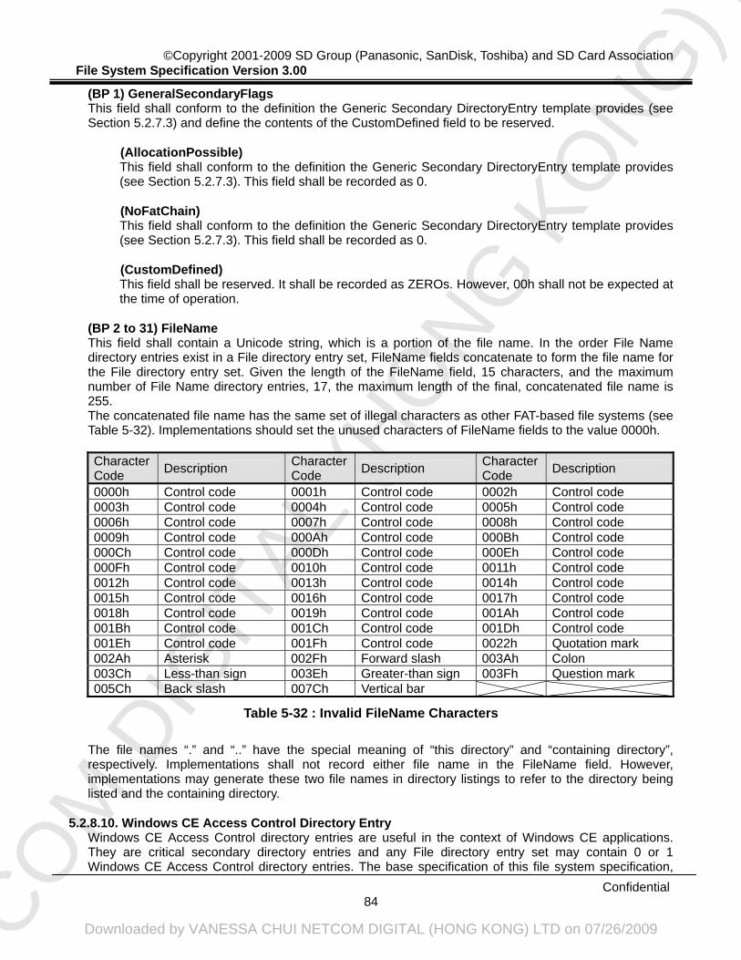
NETCO
M D
IGIT
AL (H
ONG
KO
NG) L
TD
Downloaded by VANESSA CHUI NETCOM DIGITAL (HONG KONG) LTD on 07/26/2009
SD Specifications Part 2
File System Specification
Version 3.00
April 16, 2009
SD Group Panasonic Corporation SanDisk Corporation Toshiba Corporation
Technical Committee SD Card Association
NETCO
M D
IGIT
AL (H
ONG
KO
NG) L
TD
Downloaded by VANESSA CHUI NETCOM DIGITAL (HONG KONG) LTD on 07/26/2009
Date Version Changes compared to previous issue March 22, 2000 1.00 Base version initial release. April 15, 2001 1.01 - One notation is added
- The description of System ID field is modified - The description of Reserved field in the Extended FDC Descriptor is
modified - The description of Reserved field in the Directory Entry is modified - Some computations are added in Annex B - Typo fixes and some clarification notes
May 9, 2006 2.00 - File System Specification V1.01 Supplemental Note is merged into base specification - New file system definition for High Capacity SD Memory Card, whose capacity is over 2GB and up to 32GB, is added
- LFN option for FAT12/16 is added - Timestamp option for FAT12/16 is added - Typo fixes and some clarification notes
April 16, 2009 3.00 - File System Specification V2.00 Supplemental Note is merged into base specification - New file system definition for Extended Capacity SD Memory Card, whose capacity is over 32GB and up to 2TB, is added - Typo fixes and some clarification notes
To the extent this proposed specification, which is being submitted for review under the IP Policy, implements, incorporates by reference or refers to any portion of versions 1.0 or 1.01 of the SD Specifications (including Parts 1 through 4), adoption of the proposed specification shall require Members utilizing the adopted specification to obtain the appropriate licenses from the SD-3C, LLC, as required for the utilization of those portion(s) of versions 1.0 or 1.01 of the SD Specifications. For example, implementation of the SD Specifications in a host device under versions 1.0 or 1.01 and under the adopted specification requires the execution of a SD Host Ancillary License Agreement with the SD-3C, LLC; and implementation of the SD Specifications under versions 1.0 or 1.01 and under the proposed specification in a SD Card containing any memory storage capability (other than for storage of executable code for a controller or microprocessor within the SD Card) requires the execution of a SD Memory Card License Agreement with the SD-3C, LLC.
NETCO
M D
IGIT
AL (H
ONG
KO
NG) L
TD
Downloaded by VANESSA CHUI NETCOM DIGITAL (HONG KONG) LTD on 07/26/2009
Publisher: SD Card Association 2400 Camino Ramon, Suite 375 San Ramon, CA 94583 USA Telephone: +1 (925) 275-6615, Fax: +1 (925) 886-4870 E-mail: [email protected]
Copyright Holders:
The SD Group Panasonic Corporation (Panasonic) SanDisk Corporation (SanDisk) Toshiba Corporation (Toshiba)
The SD Card Association Notes: The copyright of all previous versions (Version 1.00 and 1.01) and all corrections or non-material changes thereto are owned by SD Group. The copyright of material changes to the previous versions (Version 1.01) are owned by SD Card Association.
Confidentiality: The contents of this document are deemed confidential information of the SD-3C LLC and/or the SD Card Association (the "Disclosers"). As such, the contents and your right to use the contents are subject to the confidentiality obligations stated in the written agreement you entered into with the Disclosers which entitled you to receive this document, such as a Non-Disclosure Agreement, the License Agreement for SDA Memory Card Specifications (also known as "LAMS"), the SD Host/Ancillary Product License Agreement (also known as "HALA") or the IP Policy.
Disclaimers: The information contained herein is presented only as a standard specification for SD Card and SD Host/Ancillary products. No responsibility is assumed by SD Card Association for any damages, any infringements of patents or other right of the third parties, which may result from its use. No license is granted by implication or otherwise under any patent or rights of SD Card Association or others.
NETCO
M D
IGIT
AL (H
ONG
KO
NG) L
TD
Downloaded by VANESSA CHUI NETCOM DIGITAL (HONG KONG) LTD on 07/26/2009
Naming Conventions • Some terms are capitalized to distinguish their definition from their common English meaning. Words
not capitalized have their common English meaning.
Numbers and Number Bases • Hexadecimal numbers are written with a lower case “h” suffix, e.g., FFFFh and 80h. • Binary numbers are written with a lower case “b” suffix (e.g., 10b). • Binary numbers larger than four digits are written with a space dividing each group of four digits, as
in 1000 0101 0010b. • All other numbers are decimal.
Key Words • May: Indicates flexibility of choice with no implied recommendation or requirement. • Shall: Indicates a mandatory requirement. Designers shall implement such mandatory
requirements to ensure interchangeability and to claim conformance with the specification. • Should: Indicates a strong recommendation but not a mandatory requirement. Designers should
give strong consideration to such recommendations, but there is still a choice in implementation.
Application Notes Some sections of this document provide guidance to the host implementers as follows: Application Note: This is an example of an application note.
NETCO
M D
IGIT
AL (H
ONG
KO
NG) L
TD
Downloaded by VANESSA CHUI NETCOM DIGITAL (HONG KONG) LTD on 07/26/2009
3.1.1. Arrangement of the Data Area................................................................................................5 3.1.1.1. Physical Address ................................................................................................................... 5 3.1.1.2. Physical Sector Number ........................................................................................................ 5 3.1.1.3. Logical Sector Number .......................................................................................................... 5 3.1.1.4. Partition Area and Regular Area ............................................................................................ 5
3.1.2. Arrangement of the User Area................................................................................................6 3.1.2.1. Clusters ................................................................................................................................. 6 3.1.2.2. Status of Clusters................................................................................................................... 6
3.1.3. Arrangement of the Partition Area ..........................................................................................7 3.1.4. Arrangement of the System Area ...........................................................................................9
3.2.3.1. Characteristics ..................................................................................................................... 15 3.2.3.2. Directory Entry Types........................................................................................................... 15 3.2.3.3. General Definition of Directory Entry Fields ......................................................................... 16 3.2.3.4. User Area............................................................................................................................. 17
4. FAT32 File System ............................................................................................................18 4.1. Volume Structure ........................................................................................................................18
4.1.1. Arrangement of the Data Area..............................................................................................18 4.1.2. Arrangement of the User Area..............................................................................................18 4.1.3. Arrangement of the Partition Area ........................................................................................19 4.1.4. Arrangement of the System Area .........................................................................................21
4.1.4.1. System Area ........................................................................................................................ 21 4.1.4.2. Partition Boot Sector and FS Info Sector ............................................................................. 21 4.1.4.3. File Allocation Table (FAT) ................................................................................................... 22
4.2.4.3. Date and Time Formats ....................................................................................................... 33 4.2.4.4. Difference from the FAT12 / FAT16 File Directories ............................................................. 33 4.2.4.5. User Area............................................................................................................................. 33
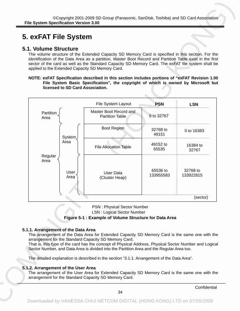
5. exFAT File System ............................................................................................................34 5.1. Volume Structure ........................................................................................................................34
5.1.1. Arrangement of the Data Area..............................................................................................34 5.1.2. Arrangement of the User Area..............................................................................................34 5.1.3. Arrangement of the Partition Area ........................................................................................35 5.1.4. Arrangement of the System Area .........................................................................................37
5.1.4.1. System Area ........................................................................................................................ 37 5.1.4.2. Main and Backup Boot Region ............................................................................................ 37 5.1.4.3. File Allocation Table (FAT) ................................................................................................... 38
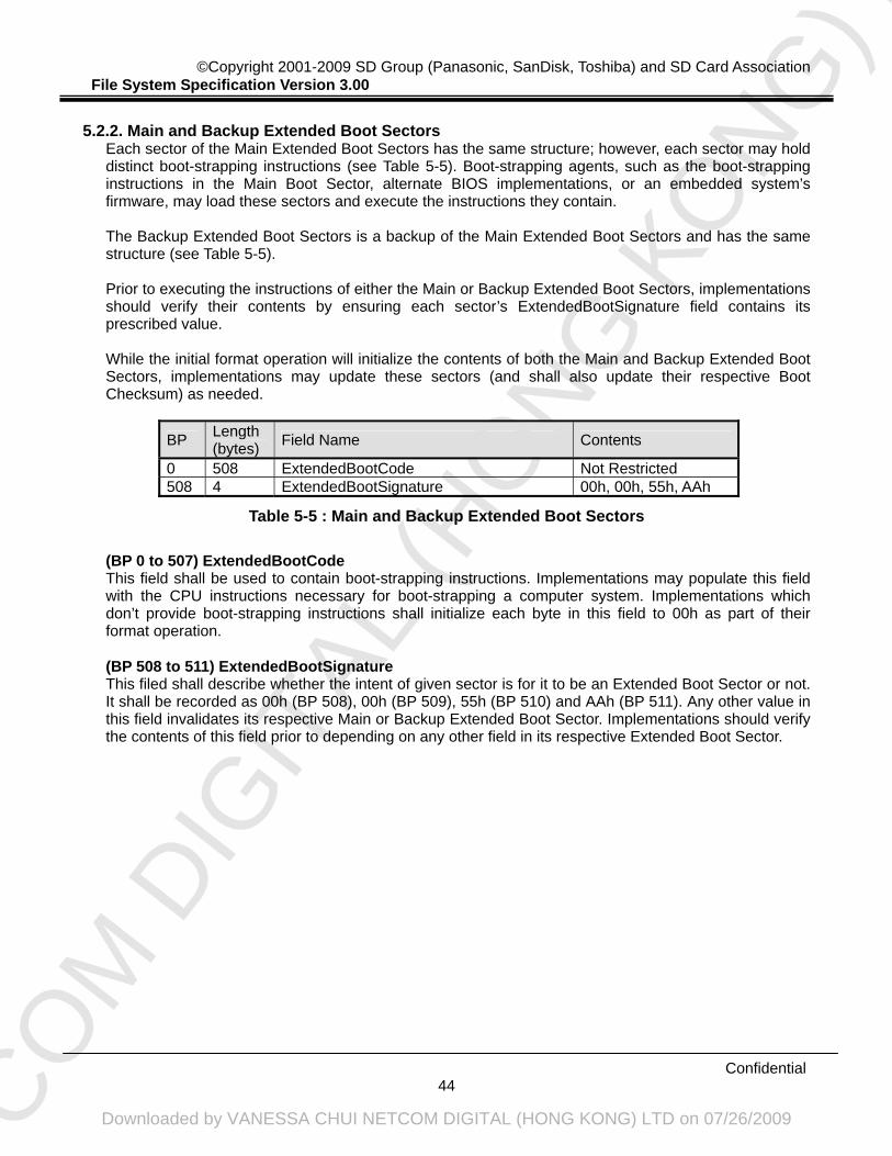
5.2. File Structure ..............................................................................................................................39 5.2.1. Main and Backup Boot Sector..............................................................................................39 5.2.2. Main and Backup Extended Boot Sectors............................................................................44 5.2.3. Main and Backup OEM Parameters.....................................................................................45
Appendix A (Normative) ....................................................................................................100 A.1 Reference..................................................................................................................................100
Appendix B (Informative) ..................................................................................................101 B.1 Abbreviations and Special Terms ..............................................................................................101 B.2 Arithmetic Notation ....................................................................................................................101
NETCO
M D
IGIT
AL (H
ONG
KO
NG) L
TD
Downloaded by VANESSA CHUI NETCOM DIGITAL (HONG KONG) LTD on 07/26/2009
B.3 Character Strings ......................................................................................................................101 B.4 Data Types ................................................................................................................................101
B.4.1 Numerical Values in One-byte Fields..................................................................................101 B.4.2 Numerical Values in Two-byte Fields..................................................................................102 B.4.3 Numerical Values in Four-byte Fields .................................................................................102 B.4.4 Numerical Values in Eight-byte Fields ................................................................................102 B.4.5 Pairs of 12-bit Integers........................................................................................................102
Appendix C (Informative) ..................................................................................................103 C.1 Appendix for FAT12/FAT16 File System....................................................................................103
C.1.1 File System Layout .............................................................................................................103 C.1.2 CHS Recommendation.......................................................................................................104 C.1.3 Sectors per Cluster and Boundary Unit Recommendation for Data Area...........................106 C.1.4 Format Parameter Computations .......................................................................................108
C.2 Appendix for FAT32 File System............................................................................................... 110 C.2.1 File System Layout ............................................................................................................. 110 C.2.2 CHS Recommendation....................................................................................................... 111 C.2.3 Sectors per Cluster and Boundary Unit Recommendation for Data Area........................... 112 C.2.4 Format Parameter Computations ....................................................................................... 113
C.3 Long File Name Implementation (optional) ............................................................................... 116 C.3.1 LFN in SD Memory Card File System ................................................................................ 116 C.3.2 FAT Long Directory Entries................................................................................................. 116 C.3.3 Ordinal Number Generation ............................................................................................... 118 C.3.4 Checksum Generation........................................................................................................ 118 C.3.5 Example illustrating persistence of a long name ................................................................ 118
C.3.5.1 Name Limits and Character Set for Long File Names .........................................................119 C.3.6 Rules Governing Name Creation and Matching ................................................................. 119
C.4 Differences from Microsoft FAT Specification............................................................................121 C.5 Appendix for exFAT File System ...............................................................................................122
C.5.1 File System Layout .............................................................................................................122 C.5.2 CHS Recommendation.......................................................................................................123 C.5.3 Sectors per Cluster and Boundary Unit Recommendation for Data Area...........................123 C.5.4 Format Parameter Computations .......................................................................................125
C.6 Differences from Microsoft exFAT Specification........................................................................127
NETCO
M D
IGIT
AL (H
ONG
KO
NG) L
TD
Downloaded by VANESSA CHUI NETCOM DIGITAL (HONG KONG) LTD on 07/26/2009
Figure 1-1 : SD Memory Card Document Structure....................................................................................... 1 Figure 3-1 : Example of Volume Structure for Data Area............................................................................... 4 Figure 4-1 : Example of Volume Structure for Data Area............................................................................. 18 Figure 4-2 : System Area Layout ................................................................................................................. 22 Figure 5-1 : Example of Volume Structure for Data Area............................................................................. 34 Figure 5-2 : System Area Layout ................................................................................................................. 38 Figure 5-3 : Continuous Information Management ...................................................................................... 94 Figure 5-4 : Example 1 of Continuous Information Management ................................................................ 95 Figure 5-5 : Example 2 of Continuous Information Management ................................................................ 96 Figure A-1 : Example of File System Layout.............................................................................................. 103 Figure A-2 : Example of File System Layout...............................................................................................111 Figure A-3 : Example of Long Directory Entries..........................................................................................119 Figure A-4 : Example of File System Layout.............................................................................................. 123
1. Overview This part specifies the file system of SD Memory Card (Secure Digital Memory Card). It manages the data recorded in SD Memory Card as files, and it enables the data exchange between the hosts supporting SD Memory Card. The card to which the file system in this specification is applied shall comply with "Part1. PHYSICAL LAYER SPECIFICATION" of SD specifications.
Figure 1-1 : SD Memory Card Document Structure
The SD Memory Card has two recordable areas. One is Data Area that user can access without mutual authentication. The other is Protected Area that user can access after mutual authentication. These two areas have file system independently with each other. This part specifies the file system for Data Area. And the one for Protected Area is specified in "Part3. SECURITY SPECIFICATION" of SD specifications. This specification specifies some file systems. The type of the file system to be used shall be uniquely decided with Card Capacity as follows. Here, Card Capacity means the total size of Data Area and Protected Area size.
Card Capacity Card Type File System Type for Data Area
~2,048MB Standard Capacity SD Memory Card FAT12 / FAT16
2,088.5MB(*) ~32,768MB
High Capacity SD Memory Card FAT32
32,896MB(*) ~2,048GB
Extended Capacity SD Memory Card exFAT
*) See NOTE described in this section.
Table 1-1 : File System Type
That is, all Standard Capacity SD Memory Cards whose capacity is 2048MB or less shall use FAT12 / FAT16 file system, and never use the other file system. Similarly, all High Capacity SD Memory Cards shall use FAT32 file system, and never use the other file system. And all Extended Capacity SD Memory Cards shall use exFAT file system, and never use the other file system. This includes the prohibition of partial format of SD Memory Card. For example, 8GB High Capacity SD Memory Card should not be formatted as 2GB card with FAT12 / FAT16 file system. In this case, whole area of 8GB should be formatted with FAT32 file system.
Security Specification (Part3)
File System Specification
(Part2)
Physical Layer Specification
(Part1)
Audio Specification
(Part4)
Other Application
Specifications
NETCO
M D
IGIT
AL (H
ONG
KO
NG) L
TD
Downloaded by VANESSA CHUI NETCOM DIGITAL (HONG KONG) LTD on 07/26/2009
This specification consists of several chapters. Chapter 2 describes the main features of this file system. Chapter 3 specifies FAT12 / FAT16 file system. Chapter 4 specifies FAT32 file system. Chapter 5 specifies exFAT file system. Appendix follows these chapters and it describes some normative references, definitions, and recommendations.
NOTE:
1. The Part 1 Physical Layer Specification Version 3.00 and Part 2 File System Specification Version 3.00 allow Standard Capacity SD Memory Cards to have capacity up to and including 2GB, High Capacity SD Memory Cards to have capacity up to and including 32GB, and Extended Capacity SD Memory Cards to have capacity up to and including 2TB. SD Memory Cards with a capacity greater than 2TB are not specified within this specification, however these higher than 2TB capacities might be addressed in future version/releases of Part 1 and Part 2 Specifications.
2. Hosts that can access (read and/or write) High Capacity SD Memory Cards shall also be able to access Standard Capacity SD Memory Cards. And hosts that can access (read and/or write) Extended Capacity SD Memory Cards shall also be able to access Standard Capacity SD Memory Cards and High Capacity SD Memory Cards.
3. Hosts that can access (read and/or write) Extended Capacity SD Memory Cards shall support exFAT file system.
4. The High Capacity SD Memory Card covered by this specification shall comply with “Part1. PHYSICAL LAYER SPECIFICATION Version 3.00” or the later version. And the High Capacity SD Memory Card supports capacity 2,088.5MB (2,088.5 × 1,024 × 1,024 bytes) or more and is limited to 32,768MB (32,768 × 1,024 × 1,024 bytes). In order to avoid the confusion caused by the border capacity, the concrete value of the minimum capacity of the High Capacity SD Memory Card shall be 2,088.5MB (2,088.5 × 1,024 × 1,024 bytes). In this case, the Protected Area size is 32MB (32 × 1,024 × 1,024 bytes) and the Data Area size is 2,056.5MB (2,056.5 × 1,024 × 1,024 bytes). And the card whose capacity is more than 2,048MB (2,048 × 1,024 × 1,024 bytes) and less than 2,088.5MB (2,088.5 × 1,024 × 1,024 bytes) is not defined by this version of the specification. Similarly, the Extended Capacity SD Memory Card covered by this specification shall comply with “Part 1. PHYSICAL LAYER SPECIFICATION Version 3.00” or the later version. And the Extended Capacity SD Memory Card supports capacity 32,896MB (32,896 × 1,024 × 1,024 bytes) or more and is limited to 2TB (2 × 1,024 × 1,024 × 1,024 × 1,024 bytes). In order to avoid the confusion caused by the border capacity, the concrete value of the minimum capacity of the Extended Capacity SD Memory Card shall be 32,896MB (32,896 × 1,024 × 1,024 bytes). In this case, the Protected Area size is 128MB (128 × 1,024 × 1,024 bytes) and the Data Area size is 32,768MB (32,768 × 1,024 × 1,024 bytes). And the card whose capacity is more than 32,768MB (32,768 × 1,024 × 1,024 bytes) and less than 32,896MB (32,896 × 1,024 × 1,024 bytes) is not defined by this version of the specification.
NETCO
M D
IGIT
AL (H
ONG
KO
NG) L
TD
Downloaded by VANESSA CHUI NETCOM DIGITAL (HONG KONG) LTD on 07/26/2009
The volume structure of the Standard Capacity SD Memory Card, whose capacity is 2GB or less, is specified in this section. It defines the logical structure of the Data Area. For the identification of the Data Area as a partition, the first sector has Master Boot Record and Partition Table. And the Standard Capacity SD Memory Card uses the FAT file system (ISO/IEC 9293) and supports both FAT12 and FAT16 as the file system type.
Figure 3-1 : Example of Volume Structure for Data Area LSN : Logical Sector Number
PSN : Physical Sector Number
PSN LSN
File Allocation Table
Root Directory
User Data
File System Layout
Partition Boot Sector
Master Boot Record and Partition Table 0 to 38
39
40 to 63
64 to 95
96 to 129791
0
1 to 24
25 to 56
57 to 129752
Regular Area
Partition Area
System Area
User Area
(sector)
NETCO
M D
IGIT
AL (H
ONG
KO
NG) L
TD
Downloaded by VANESSA CHUI NETCOM DIGITAL (HONG KONG) LTD on 07/26/2009
3.1.1. Arrangement of the Data Area 3.1.1.1. Physical Address
Each sector shall be identified by a Physical Address comprising the parameters of SD Memory Card’s own.
3.1.1.2. Physical Sector Number
Each sector on a volume shall be identified by a Physical Sector Number. There shall be a one-to-one correspondence between Physical Address and Physical Sector Number. The Physical Sector Numbers shall be assigned in an ascending sequence, beginning with 0.
3.1.1.3. Logical Sector Number
Each sector on a partition shall be identified by a Logical Sector Number. The first sector of the partition shall be assigned 0 as Logical Sector Number. There shall be a one-to-one correspondence between Physical Sector Number.
3.1.1.4. Partition Area and Regular Area
The space on Data Area shall be divided into two parts: Partition Area and Regular Area. And the Regular Area shall be divided into System Area and User Area. The Partition Area shall occupy sectors with the Physical Sector Numbers 0 to NOM-1, where NOM is the number of sectors in the Master Boot Record and Partition Table. The Regular Area is a partition of the volume, and divided into System Area and User Area. The System Area shall occupy sectors with the Physical Sector Numbers NOM to NOM+SSA-1, where SSA is the number of sectors in the System Area. The System Area shall contain Descriptors that specify the recording format of the Regular Area. No part of any file shall be contained in the System Area. The User Area shall occupy sectors with the Physical Sector Numbers starting with NOM+SSA. The User Area shall contain files and directories, and be recorded user data.
NETCO
M D
IGIT
AL (H
ONG
KO
NG) L
TD
Downloaded by VANESSA CHUI NETCOM DIGITAL (HONG KONG) LTD on 07/26/2009
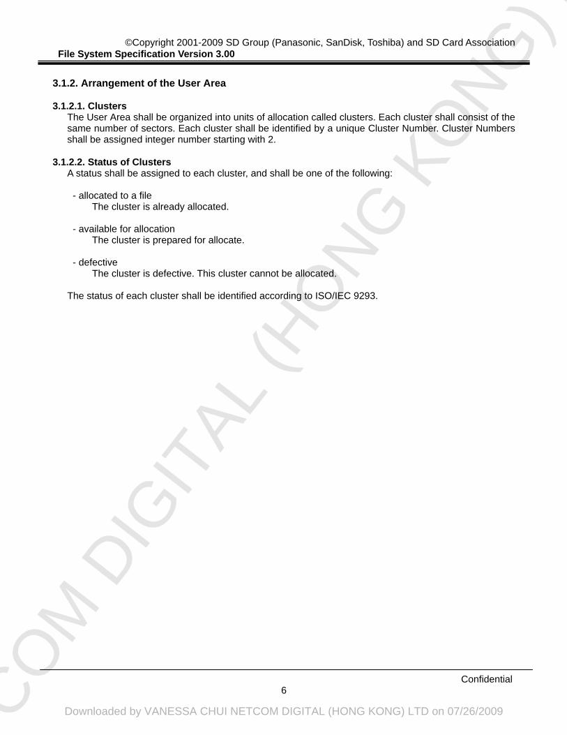
3.1.2. Arrangement of the User Area 3.1.2.1. Clusters
The User Area shall be organized into units of allocation called clusters. Each cluster shall consist of the same number of sectors. Each cluster shall be identified by a unique Cluster Number. Cluster Numbers shall be assigned integer number starting with 2.
3.1.2.2. Status of Clusters
A status shall be assigned to each cluster, and shall be one of the following: - allocated to a file
The cluster is already allocated.
- available for allocation The cluster is prepared for allocate.
- defective The cluster is defective. This cluster cannot be allocated.
The status of each cluster shall be identified according to ISO/IEC 9293.
NETCO
M D
IGIT
AL (H
ONG
KO
NG) L
TD
Downloaded by VANESSA CHUI NETCOM DIGITAL (HONG KONG) LTD on 07/26/2009
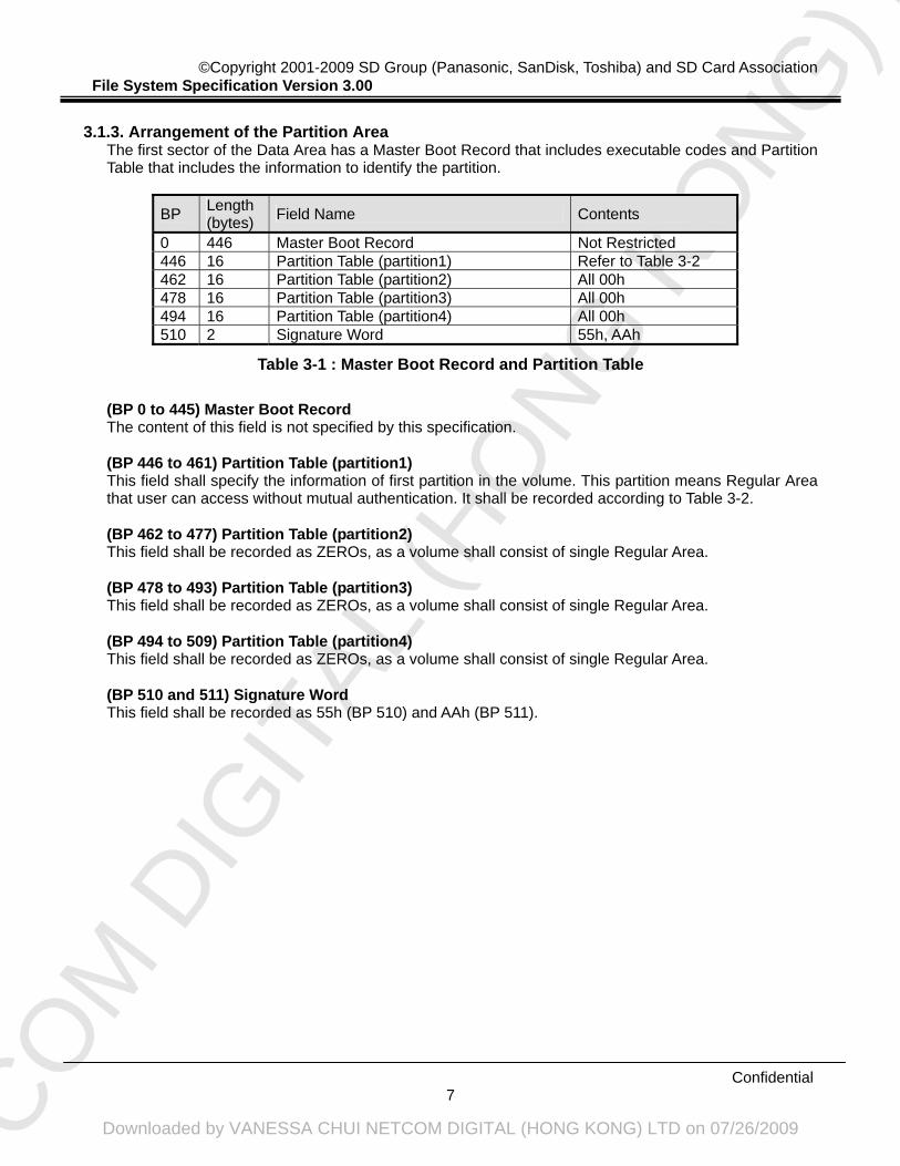
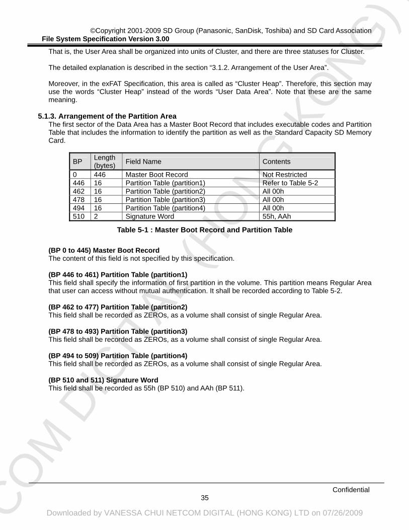
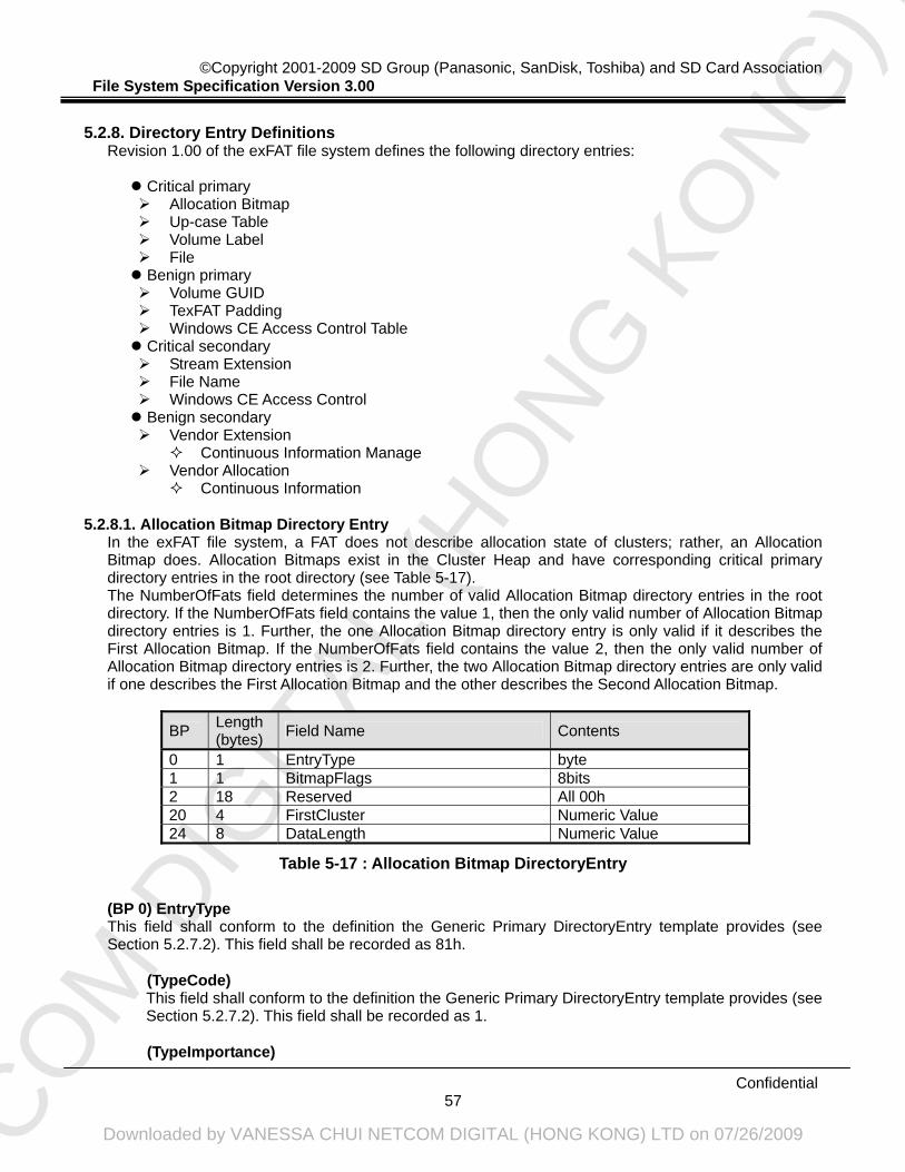
The first sector of the Data Area has a Master Boot Record that includes executable codes and Partition Table that includes the information to identify the partition.
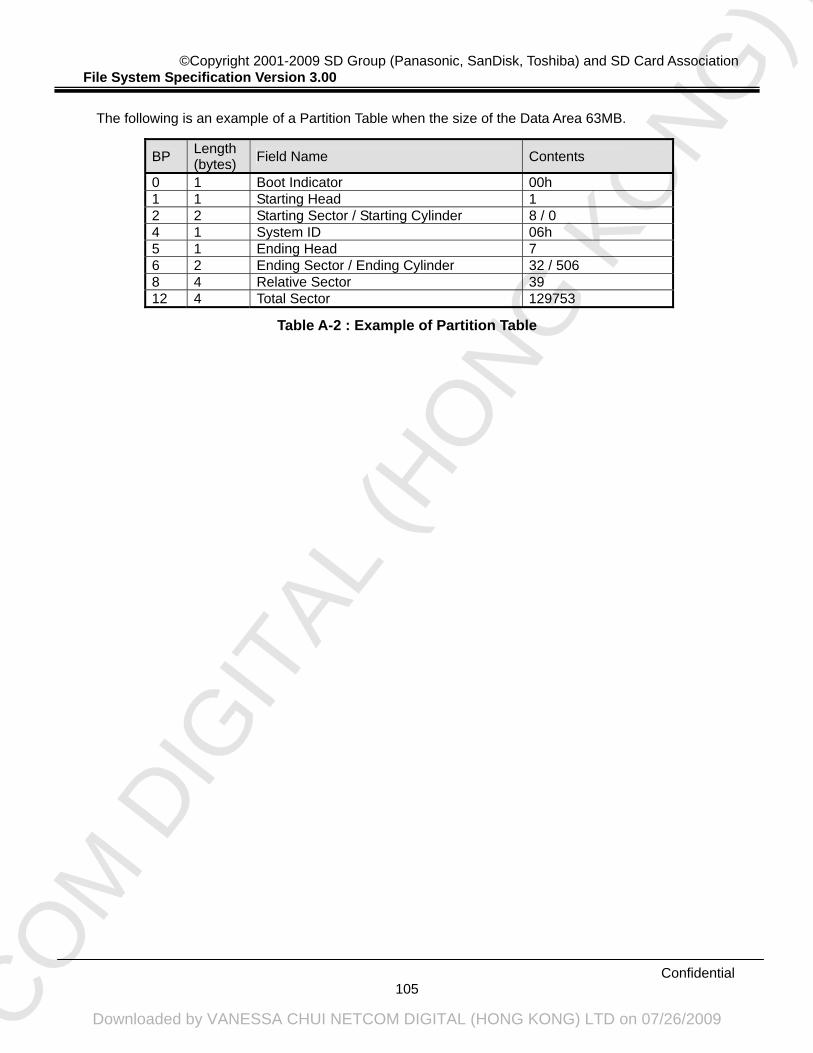
BP Length (bytes) Field Name Contents
0 446 Master Boot Record Not Restricted 446 16 Partition Table (partition1) Refer to Table 3-2 462 16 Partition Table (partition2) All 00h 478 16 Partition Table (partition3) All 00h 494 16 Partition Table (partition4) All 00h 510 2 Signature Word 55h, AAh
Table 3-1 : Master Boot Record and Partition Table
(BP 0 to 445) Master Boot Record The content of this field is not specified by this specification.
(BP 446 to 461) Partition Table (partition1) This field shall specify the information of first partition in the volume. This partition means Regular Area that user can access without mutual authentication. It shall be recorded according to Table 3-2.
(BP 462 to 477) Partition Table (partition2) This field shall be recorded as ZEROs, as a volume shall consist of single Regular Area.
(BP 478 to 493) Partition Table (partition3) This field shall be recorded as ZEROs, as a volume shall consist of single Regular Area.
(BP 494 to 509) Partition Table (partition4) This field shall be recorded as ZEROs, as a volume shall consist of single Regular Area.
(BP 510 and 511) Signature Word This field shall be recorded as 55h (BP 510) and AAh (BP 511).
NETCO
M D
IGIT
AL (H
ONG
KO
NG) L
TD
Downloaded by VANESSA CHUI NETCOM DIGITAL (HONG KONG) LTD on 07/26/2009
0 1 Boot Indicator 00h or 80h 1 1 Starting Head Numeric Value 2 2 Starting Sector / Starting Cylinder Numeric Value 4 1 System ID 01h or 04h or 06h 5 1 Ending Head Numeric Value 6 2 Ending Sector / Ending Cylinder Numeric Value 8 4 Relative Sector Numeric Value 12 4 Total Sector Numeric Value
Table 3-2 : Partition Table
(BP 0) Boot Indicator This field shall be recorded as 80h if SD Memory Card is used for boot. Otherwise, this field shall be recorded as 00h.
(BP 1) Starting Head This field shall specify the starting head of the partition.
(BP 2 and 3) Starting Sector / Starting Cylinder This field shall specify the starting sector and cylinder of the partition. 6 bits (Bit 0 to Bit 5 in BP 2) in this field shall be used for starting sector. 10 bits (Bit 6 and Bit 7 in BP 2, Bit 0 to Bit 7 in BP 3) in this field shall be used for starting cylinder.
(BP 4) System ID This field shall be determined only by partition length regardless of file system types (FAT12/FAT16). It shall be recorded as 01h if the partition size is less than 32680 sectors. And it shall be recorded as 04h if the one is less than 65536 sectors. Otherwise, it shall be recorded as 06h.
(BP 5) Ending Head This field shall specify the ending head of the partition.
(BP 6 and 7) Ending Sector / Ending Cylinder This field shall specify the ending sector and cylinder of the partition. 6 bits (Bit 0 to Bit 5 in BP 6) in this field shall be used for ending sector. 10 bits (Bit 6 and Bit 7 in BP 6, Bit 0 to Bit 7 in BP 7) in this field shall be used for ending cylinder.
(BP 8 to 11) Relative Sector This field shall specify the number of sectors existing before the starting sector of this partition.
(BP 12 to 15) Total Sector This field shall specify the number of sectors on the partition.
NETCO
M D
IGIT
AL (H
ONG
KO
NG) L
TD
Downloaded by VANESSA CHUI NETCOM DIGITAL (HONG KONG) LTD on 07/26/2009
3.1.4. Arrangement of the System Area 3.1.4.1. System Area
The System Area shall contain the Partition Boot Sector, the Root Directory and the File Allocation Table (FAT) recorded twice.
3.1.4.2. Partition Boot Sector
The first sector of the System Area shall contain the Partition Boot Sector including the FDC Descriptor. The FDC Descriptor shall contain the parameters for the partition.
3.1.4.3. File Allocation Table (FAT)
The FAT shall contain a Format Identifier and some entries, each of which indicates cluster of the User Area. These entries shall be numbered consecutively starting with 2 and the Entry Number shall be equal to the Cluster Number of the corresponding cluster. Each entry in the FAT shall indicate the status of the corresponding cluster. The FAT entries shall be used to identify the set of clusters that are allocated to each file.
3.1.4.4. Root Directory
The Root Directory shall be recorded in the System Area following the second occurrence of the FAT.
NETCO
M D
IGIT
AL (H
ONG
KO
NG) L
TD
Downloaded by VANESSA CHUI NETCOM DIGITAL (HONG KONG) LTD on 07/26/2009
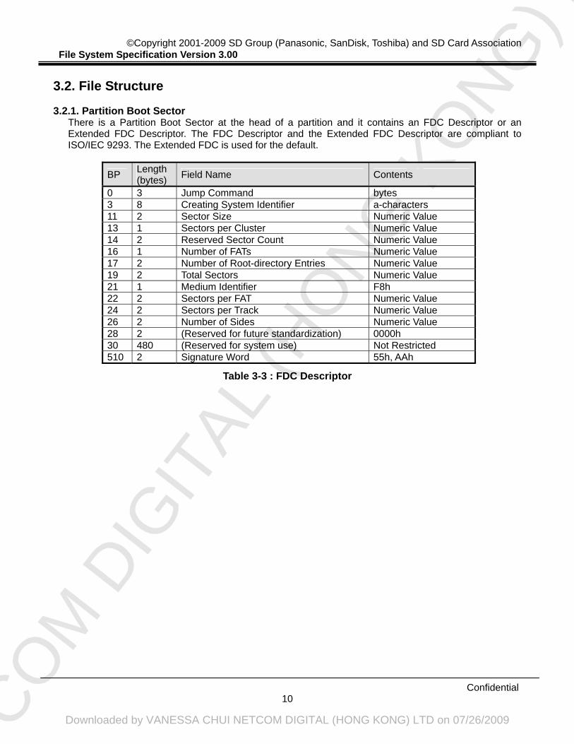
There is a Partition Boot Sector at the head of a partition and it contains an FDC Descriptor or an Extended FDC Descriptor. The FDC Descriptor and the Extended FDC Descriptor are compliant to ISO/IEC 9293. The Extended FDC is used for the default.
BP Length (bytes) Field Name Contents
0 3 Jump Command bytes 3 8 Creating System Identifier a-characters 11 2 Sector Size Numeric Value 13 1 Sectors per Cluster Numeric Value 14 2 Reserved Sector Count Numeric Value 16 1 Number of FATs Numeric Value 17 2 Number of Root-directory Entries Numeric Value 19 2 Total Sectors Numeric Value 21 1 Medium Identifier F8h 22 2 Sectors per FAT Numeric Value 24 2 Sectors per Track Numeric Value 26 2 Number of Sides Numeric Value 28 2 (Reserved for future standardization) 0000h 30 480 (Reserved for system use) Not Restricted 510 2 Signature Word 55h, AAh
Table 3-3 : FDC Descriptor
NETCO
M D
IGIT
AL (H
ONG
KO
NG) L
TD
Downloaded by VANESSA CHUI NETCOM DIGITAL (HONG KONG) LTD on 07/26/2009
0 3 Jump Command bytes 3 8 Creating System Identifier a-characters 11 2 Sector Size Numeric Value 13 1 Sectors per Cluster Numeric Value 14 2 Reserved Sector Count Numeric Value 16 1 Number of FATs Numeric Value 17 2 Number of Root-directory Entries Numeric Value 19 2 Total Sectors Numeric Value 21 1 Medium Identifier F8h 22 2 Sectors per FAT Numeric Value 24 2 Sectors per Track Numeric Value 26 2 Number of Sides Numeric Value 28 4 Number of Hidden Sectors Numeric Value 32 4 Total Sectors Numeric Value 36 1 Physical Disk Number 80h 37 1 Reserved 00h 38 1 Extended Boot Record Signature 29h 39 4 Volume ID Number Numeric Value 43 11 Volume Label d-characters 54 8 File System Type d-characters 62 448 (Reserved for system use) Not Restricted 510 2 Signature Word 55h, AAh
Table 3-4 : Extended FDC Descriptor
(BP 0 to 2) Jump Command This field shall specify the jump command to the boot program. It shall be recorded as EBh (BP 0), XXh (BP 1) and 90h (BP 2), or E9h (BP 0), XXh (BP 1) and XXh (BP 2). XXh means that the value is not specified in this specification.
(BP 3 to 10) Creating System Identifier This field shall specify identification for the system. This field shall be recorded using a-characters and according to ISO/IEC 9293 9.
(BP 11 and 12) Sector Size This field shall specify the size of a sector in bytes. It shall be recorded as the number 512.
(BP 13) Sectors per Cluster This field shall specify the number of sectors per cluster. It shall be recorded the following number: 1, 2, 4, 8, 16, 32 or 64. The Cluster Size shall be determined taking the erase block size of physical layer into account. This field should be recorded complying with the recommendation of this specification. Detailed explanations for the recommendation are described in Appendix C.1.3.
(BP 14 and 15) Reserved Sector Count This field shall specify the number of sectors reserved for system use. It shall be recorded as the number 1.
(BP 16) Number of FATs This field shall specify the number of FATs. It shall be recorded as the number 2.
NETCO
M D
IGIT
AL (H
ONG
KO
NG) L
TD
Downloaded by VANESSA CHUI NETCOM DIGITAL (HONG KONG) LTD on 07/26/2009
(BP 17 and 18) Number of Root-directory Entries This field shall specify the number of entries in the Root Directory. It shall be recorded as the number 512.
(BP 19 and 20) Total Sectors This field shall specify the number of sectors on the partition. It shall be recorded according to ISO/IEC 9293 9.
(BP 21) Medium Identifier This field shall be recorded as F8h for this specification.
(BP 22 and 23) Sectors per FAT This field shall specify the number of sectors that shall be occupied by each FAT. It shall be recorded according to ISO/IEC 9293 9.
(BP 24 and 25) Sectors per Track This field shall specify the number of sectors in each track. This parameter depends on the SD Memory Card’s parameter. It shall be recorded according to ISO/IEC 9293 9. This field should be recorded complying with the recommendation of this specification. Detailed explanations for the recommendation are described in Appendix C.1.2.
(BP 26 and 27) Number of Sides This field shall specify the number of sides that can be recorded. This parameter depends on the SD Memory Card’s parameter. It shall be recorded according to ISO/IEC 9293 9. This field should be recorded complying with the recommendation of this specification. Detailed explanations for the recommendation are described in Appendix C.1.2.
(BP 28 and 29) Field reserved for future standardization This field shall be reserved for future standardization. It shall contain only ZEROs.
(BP 30 to 509) Field reserved for system use This field shall be reserved for system use. It shall not be specified in this specification.
(BP 510 and 511) Signature Word This field shall be recorded as 55h (BP 510) and AAh (BP 511).
(Extended FDC Descriptor BP 28 to 31) Number of Hidden Sectors This field shall specify the number of sectors existing before the starting sector of this partition.
(Extended FDC Descriptor BP 32 to 35) Total Sectors This field shall specify the number of sectors on the partition if the field in BP 19 and 20 is recorded as ZEROs. It shall be recorded according to ISO/IEC 9293 9.
(Extended FDC Descriptor BP 36) Physical Disk Number This field shall specify the BIOS physical disk number. This field shall be recorded as 80h.
(Extended FDC Descriptor BP 37) Reserved This field shall be reserved for future standardization. It shall be recorded as ZEROs. It shall be recorded according to ISO/IEC 9293 9. However, since a value other than 00h may be set on other devices, 00h shall not be expected at the time of operation.
(Extended FDC Descriptor BP 38) Extended Boot Record Signature
NETCO
M D
IGIT
AL (H
ONG
KO
NG) L
TD
Downloaded by VANESSA CHUI NETCOM DIGITAL (HONG KONG) LTD on 07/26/2009
This field shall be used to identify the descriptor type in the Extended FDC Descriptor when either BP 19 or BP 20 is not recorded as ZEROs. This field shall be recorded as 29h.
(Extended FDC Descriptor BP 39 to 42) Volume ID Number This field shall specify the volume identification number. It shall be recorded according to ISO/IEC 9293 9.
(Extended FDC Descriptor BP 43 to 53) Volume Label This field shall specify the volume label. It shall be recorded according to ISO/IEC 9293 9.
(Extended FDC Descriptor BP 54 to 61) File System Type This field shall specify the type of the file system. It shall be recorded according to ISO/IEC 9293 9.
(Extended FDC Descriptor BP 62 to 509) Field reserved for system use This field shall be reserved for system use. It shall not be specified in this specification.
(Extended FDC Descriptor BP 510 and 511) Signature Word This field shall be recorded as 55h (BP 510) and AAh (BP 511).
NETCO
M D
IGIT
AL (H
ONG
KO
NG) L
TD
Downloaded by VANESSA CHUI NETCOM DIGITAL (HONG KONG) LTD on 07/26/2009
The File Allocation Table supports both the 12-bit FAT and the 16-bit FAT. The FAT structure is compliant to ISO/IEC 9293. The FAT type shall be determined by the number of clusters that depends on the parameter from the physical layer. If the cluster number is less than 4085, FAT12 shall be used. Otherwise, FAT16 shall be used. The first byte of the FAT shall specify the format identifier and be recorded F8h. In case of FAT12, the byte 2 and 3 shall be recorded as FFh each. In case of FAT16, the byte 2, 3 and 4 shall be recorded as FFh each. The sectors of the FAT may include unused area, because the number of clusters shall determine the FAT size in byte. This unused area shall be recorded as ZEROs.
FAT Entry Value FAT12 FAT16
Contents
000h 0000h Indicates that the corresponding cluster is not in use and may be allocated to a file or a directory.
002h to MAX
0002h to MAX
Indicates that the corresponding cluster is already allocated. The value of the entry is the cluster number of the next cluster following this corresponding cluster. Max shall be the Maximum Cluster Number.
MAX+1 to FF6h
MAX+1 to FFF6h
Shall be reserved for future standardization and shall not be used.
FF7h FFF7h Indicates that the corresponding cluster has a defective cluster.FF8h to FFFh
FFF8h to FFFFh
The corresponding cluster is already allocated, and it is the final cluster of the file.
Table 3-5 : FAT Entry Value
NETCO
M D
IGIT
AL (H
ONG
KO
NG) L
TD
Downloaded by VANESSA CHUI NETCOM DIGITAL (HONG KONG) LTD on 07/26/2009
A Directory is a Descriptor that shall contain a set of Directory entries each of which identifies a file, a Volume Label, another Directory or is unused. The maximum number of Directory entries in a Directory excluding root directory is 65536. The Short File Name entry storing file name as 8.3 format shall be supported as mandatory. And the character code permitted by the ISO/IEC 9293 can be used for this type of Directory entry. Moreover, hosts can also support Long File Name (LFN) entry as optional. If host doesn’t support Long File Name, it may ignore Long File Name entries, and refers to only the file name of 8.3 format that is stored with the LFN. NOTE: The Long File Name feature is described in Appendix C.3.
3.2.3.2. Directory Entry Types
Directory entries shall contain descriptive information about the files recorded on the partition. There are some types of these entries as below:
- File Entry
A File Entry shall specify information of a file.
- Volume Label Entry A Volume Label Entry shall specify the volume label of the partition.
- Sub-directory Pointer Entry A Sub-directory Pointer Entry shall specify information of a directory.
- Sub-directory Identifier Entry A Sub-directory Identifier Entry shall identify a file as a Sub-directory.
- Sub-directory Parent Pointer Entry A Sub-directory Parent Pointer Entry shall specify information of its parent directory.
- Not-currently-in-use Entry A Not-currently-in-use Entry shall specify the entry is not used and able to allocate.
- Never-used Entry A Never-used Entry shall specify the end of the directory. It shall not appear before any other type of Directory entry.
These entries shall be recorded according to ISO/IEC 9293 11.
NETCO
M D
IGIT
AL (H
ONG
KO
NG) L
TD
Downloaded by VANESSA CHUI NETCOM DIGITAL (HONG KONG) LTD on 07/26/2009
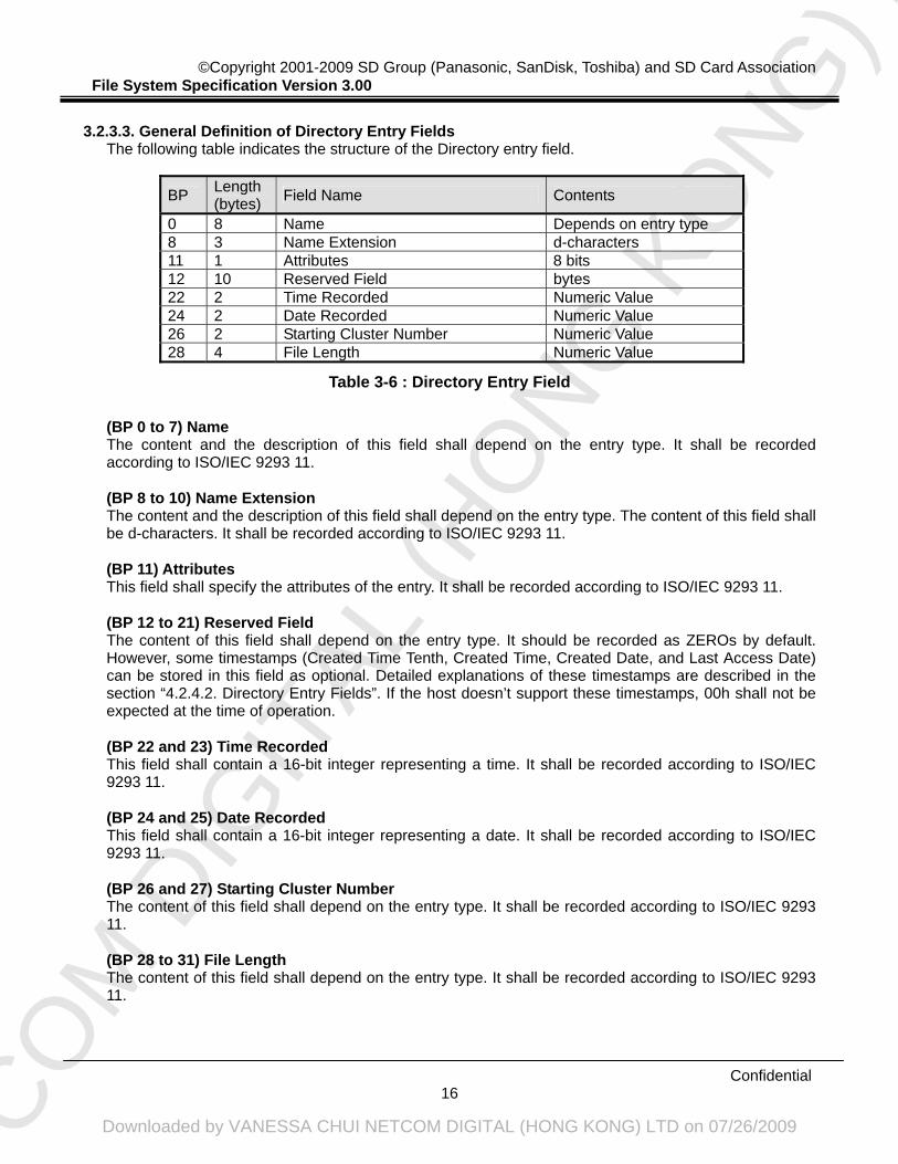
3.2.3.3. General Definition of Directory Entry Fields
The following table indicates the structure of the Directory entry field.
BP Length (bytes) Field Name Contents
0 8 Name Depends on entry type 8 3 Name Extension d-characters 11 1 Attributes 8 bits 12 10 Reserved Field bytes 22 2 Time Recorded Numeric Value 24 2 Date Recorded Numeric Value 26 2 Starting Cluster Number Numeric Value 28 4 File Length Numeric Value
Table 3-6 : Directory Entry Field
(BP 0 to 7) Name The content and the description of this field shall depend on the entry type. It shall be recorded according to ISO/IEC 9293 11.
(BP 8 to 10) Name Extension The content and the description of this field shall depend on the entry type. The content of this field shall be d-characters. It shall be recorded according to ISO/IEC 9293 11.
(BP 11) Attributes This field shall specify the attributes of the entry. It shall be recorded according to ISO/IEC 9293 11.
(BP 12 to 21) Reserved Field The content of this field shall depend on the entry type. It should be recorded as ZEROs by default. However, some timestamps (Created Time Tenth, Created Time, Created Date, and Last Access Date) can be stored in this field as optional. Detailed explanations of these timestamps are described in the section “4.2.4.2. Directory Entry Fields”. If the host doesn’t support these timestamps, 00h shall not be expected at the time of operation.
(BP 22 and 23) Time Recorded This field shall contain a 16-bit integer representing a time. It shall be recorded according to ISO/IEC 9293 11.
(BP 24 and 25) Date Recorded This field shall contain a 16-bit integer representing a date. It shall be recorded according to ISO/IEC 9293 11.
(BP 26 and 27) Starting Cluster Number The content of this field shall depend on the entry type. It shall be recorded according to ISO/IEC 9293 11.
(BP 28 to 31) File Length The content of this field shall depend on the entry type. It shall be recorded according to ISO/IEC 9293 11.
NETCO
M D
IGIT
AL (H
ONG
KO
NG) L
TD
Downloaded by VANESSA CHUI NETCOM DIGITAL (HONG KONG) LTD on 07/26/2009
The User Area shall be organized into clusters. Each cluster has a Cluster Number respectively. The first cluster in the User Area is corresponding to Cluster Number 2. Although it is available to read/write by the sector, it is necessary to transact reading/writing with the unit whose minimum size is the same as that of the recommended reading/writing at the physical layer. Other than that, there are no special restrictions for the SD Memory Card file system.
NETCO
M D
IGIT
AL (H
ONG
KO
NG) L
TD
Downloaded by VANESSA CHUI NETCOM DIGITAL (HONG KONG) LTD on 07/26/2009
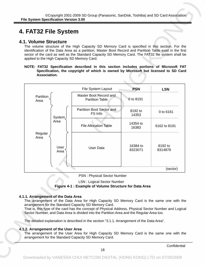
The volume structure of the High Capacity SD Memory Card is specified in this section. For the identification of the Data Area as a partition, Master Boot Record and Partition Table exist in the first sector of the card as well as the Standard Capacity SD Memory Card. The FAT32 file system shall be applied to the High Capacity SD Memory Card.
NOTE: FAT32 Specification described in this section includes portions of Microsoft FAT
Specification, the copyright of which is owned by Microsoft but licensed to SD Card Association.
Figure 4-1 : Example of Volume Structure for Data Area 4.1.1. Arrangement of the Data Area
The arrangement of the Data Area for High Capacity SD Memory Card is the same one with the arrangement for the Standard Capacity SD Memory Card. That is, this type of the card has the concept of Physical Address, Physical Sector Number and Logical Sector Number, and Data Area is divided into the Partition Area and the Regular Area too. The detailed explanation is described in the section “3.1.1. Arrangement of the Data Area”.
4.1.2. Arrangement of the User Area
The arrangement of the User Area for High Capacity SD Memory Card is the same one with the arrangement for the Standard Capacity SD Memory Card.
LSN : Logical Sector Number
PSN : Physical Sector Number
File Allocation Table
User Data
File System Layout
Partition Boot Sector and FS Info
Master Boot Record and Partition Table
PSN
0 to 8191
8192 to 14353
14354 to 16383
16384 to 8323071
LSN
0 to 6161
6162 to 8191
8192 to 8314879
Regular Area
Partition Area
System Area
User Area
(sector)
NETCO
M D
IGIT
AL (H
ONG
KO
NG) L
TD
Downloaded by VANESSA CHUI NETCOM DIGITAL (HONG KONG) LTD on 07/26/2009
That is, the User Area shall be organized into units of Cluster, and there are three statuses for Cluster. The detailed explanation is described in the section “3.1.2. Arrangement of the User Area”.
4.1.3. Arrangement of the Partition Area
The first sector of the Data Area has a Master Boot Record that includes executable codes and Partition Table that includes the information to identify the partition as well as the Standard Capacity SD Memory Card.
BP Length (bytes) Field Name Contents
0 446 Master Boot Record Not Restricted 446 16 Partition Table (partition1) Refer to Table 4-2 462 16 Partition Table (partition2) All 00h 478 16 Partition Table (partition3) All 00h 494 16 Partition Table (partition4) All 00h 510 2 Signature Word 55h, AAh
Table 4-1 : Master Boot Record and Partition Table
(BP 0 to 445) Master Boot Record The content of this field is not specified by this specification.
(BP 446 to 461) Partition Table (partition1) This field shall specify the information of first partition in the volume. This partition means Regular Area that user can access without mutual authentication. It shall be recorded according to Table 4-2.
(BP 462 to 477) Partition Table (partition2) This field shall be recorded as ZEROs, as a volume shall consist of single Regular Area.
(BP 478 to 493) Partition Table (partition3) This field shall be recorded as ZEROs, as a volume shall consist of single Regular Area.
(BP 494 to 509) Partition Table (partition4) This field shall be recorded as ZEROs, as a volume shall consist of single Regular Area.
(BP 510 and 511) Signature Word This field shall be recorded as 55h (BP 510) and AAh (BP 511).
NETCO
M D
IGIT
AL (H
ONG
KO
NG) L
TD
Downloaded by VANESSA CHUI NETCOM DIGITAL (HONG KONG) LTD on 07/26/2009
0 1 Boot Indicator 00h or 80h 1 1 Starting Head Numeric Value 2 2 Starting Sector / Starting Cylinder Numeric Value 4 1 System ID 0Bh or 0Ch 5 1 Ending Head Numeric Value 6 2 Ending Sector / Ending Cylinder Numeric Value 8 4 Relative Sector Numeric Value 12 4 Total Sector Numeric Value
Table 4-2 : Partition Table
(BP 0) Boot Indicator This field shall be recorded as 80h if SD Memory Card is used for boot. Otherwise, this field shall be recorded as 00h.
(BP 1) Starting Head This field shall specify the starting head of the partition. If the starting location of the partition exceeds 8032.5MB (8,422,686,720Bytes), this field shall be recorded as FEh.
(BP 2 and 3) Starting Sector / Starting Cylinder This field shall specify the starting sector and cylinder of the partition. 6 bits (Bit 0 to Bit 5 in BP 2) in this field shall be used for starting sector. 10 bits (Bit 6 and Bit 7 in BP 2, Bit 0 to Bit 7 in BP 3) in this field shall be used for starting cylinder. If the starting location of the partition exceeds 8032.5MB (8,422,686,720Bytes), this field shall be recorded as FFFFh.
(BP 4) System ID This field shall be recorded as 0Bh if the ending location of the partition is less than 8032.5MB (8,422,686,720Bytes). Otherwise, this field shall be recorded as 0Ch.
(BP 5) Ending Head This field shall specify the ending head of the partition. If the ending location of the partition exceeds 8032.5MB (8,422,686,720Bytes), this field shall be recorded as FEh.
(BP 6 and 7) Ending Sector / Ending Cylinder This field shall specify the ending sector and cylinder of the partition. 6 bits (Bit 0 to Bit 5 in BP 6) in this field shall be used for ending sector. 10 bits (Bit 6 and Bit 7 in BP 6, Bit 0 to Bit 7 in BP 7) in this field shall be used for ending cylinder. If the ending location of the partition exceeds 8032.5MB (8,422,686,720Bytes), this field shall be recorded as FFFFh.
(BP 8 to 11) Relative Sector This field shall specify the number of sectors existing before the starting sector of this partition. The starting sector of the partition should be aligned to the Boundary Unit specified in Appendix C.2. Detailed explanations for the alignment are described in Appendix C.2.
(BP 12 to 15) Total Sector This field shall specify the number of sectors on the partition.
NETCO
M D
IGIT
AL (H
ONG
KO
NG) L
TD
Downloaded by VANESSA CHUI NETCOM DIGITAL (HONG KONG) LTD on 07/26/2009
4.1.4. Arrangement of the System Area 4.1.4.1. System Area
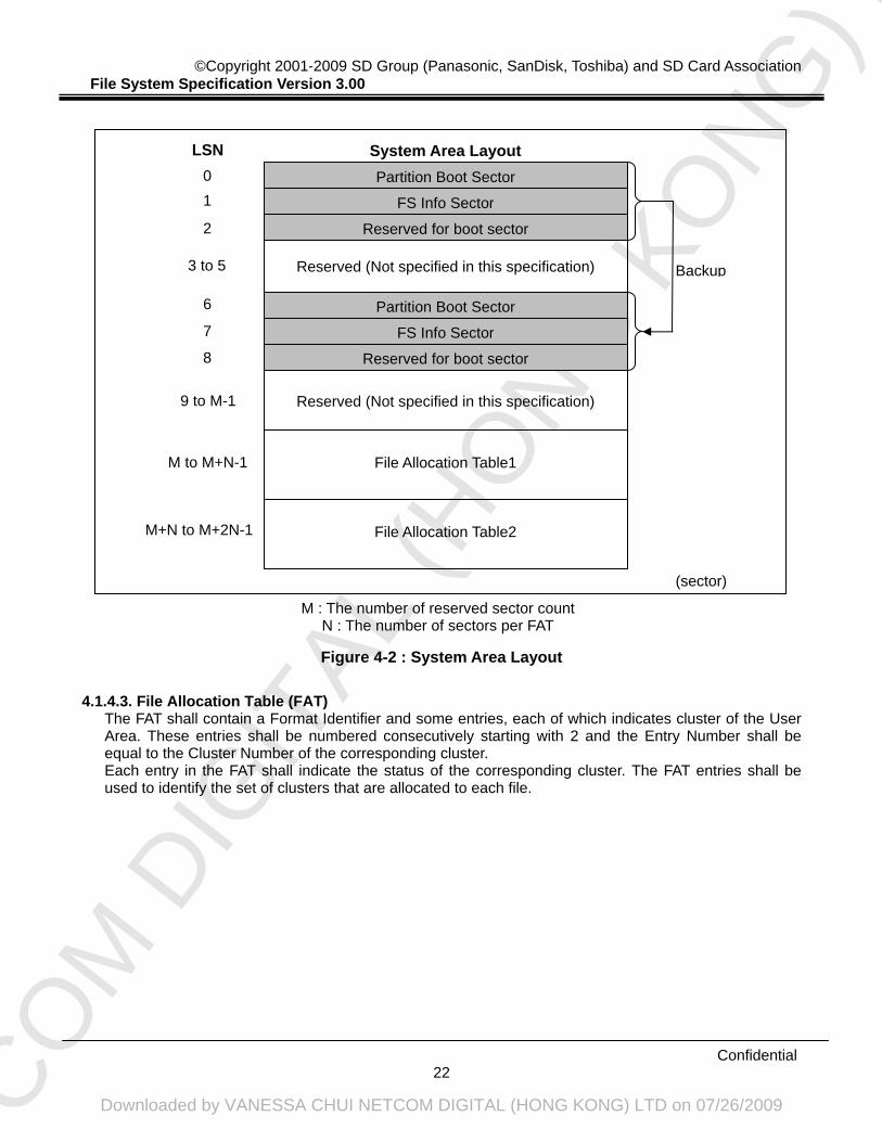
The System Area shall contain the Partition Boot Sector, the FS Info Sector and the File Allocation Table (FAT). These sectors shall be recorded twice on the card for the sake of backup. FAT32 has no reserved area for Root Directory. It shall be located in the User Data Area like the other directories.
4.1.4.2. Partition Boot Sector and FS Info Sector
The first sector of the System Area shall contain the Partition Boot Sector. It shall contain the parameters for the partition like cluster size, partition size, etc. The second sector of the System Area shall contain the FS Info Sector. It shall contain the additional information like free cluster count, next free cluster, etc. The third sector of the System Area shall be reserved for boot sectors. This sector has the signature word. That is, 55h shall be recorded in BP 510, and AAh shall be recorded in BP 511. The other bytes in this third sector shall be reserved for system use and they shall not be specified in this specification. The size of this area shall be recorded in the Reserved Sector Count field in the Partition Boot Sector. In this specification, the size should be used for the alignment of User Data area. For more details, see Appendix C.2. All 3 sectors described above shall be recorded twice on the card. They shall be recorded in the Logical Sector Number (LSN) 0 to 2 and 6 to 8 as follows.
NETCO
M D
IGIT
AL (H
ONG
KO
NG) L
TD
Downloaded by VANESSA CHUI NETCOM DIGITAL (HONG KONG) LTD on 07/26/2009
Figure 4-2 : System Area Layout 4.1.4.3. File Allocation Table (FAT)
The FAT shall contain a Format Identifier and some entries, each of which indicates cluster of the User Area. These entries shall be numbered consecutively starting with 2 and the Entry Number shall be equal to the Cluster Number of the corresponding cluster. Each entry in the FAT shall indicate the status of the corresponding cluster. The FAT entries shall be used to identify the set of clusters that are allocated to each file.
M : The number of reserved sector count N : The number of sectors per FAT
File Allocation Table2
Reserved (Not specified in this specification)
Partition Boot Sector
LSN
0
FS Info Sector1
Reserved for boot sector2
3 to 5
System Area Layout
Reserved (Not specified in this specification)
Partition Boot Sector6
FS Info Sector7
Reserved for boot sector8
9 to M-1
File Allocation Table1 M to M+N-1
Backup
M+N to M+2N-1
(sector)
NETCO
M D
IGIT
AL (H
ONG
KO
NG) L
TD
Downloaded by VANESSA CHUI NETCOM DIGITAL (HONG KONG) LTD on 07/26/2009
There is a Partition Boot Sector at the head of a partition. For FAT32 file system, some fields are extended from Extended FDC Descriptor of ISO/IEC 9293. Partition Boot Sector shall be recorded twice as described before.
BP Length (bytes) Field Name Contents
0 3 Jump Command bytes 3 8 Creating System Identifier bytes 11 2 Sector Size Numeric Value 13 1 Sectors per Cluster Numeric Value 14 2 Reserved Sector Count Numeric Value 16 1 Number of FATs Numeric Value 17 2 Number of Root-directory Entries Numeric Value 19 2 Total Sectors Numeric Value 21 1 Medium Identifier F8h 22 2 Sectors per FAT Numeric Value 24 2 Sectors per Track Numeric Value 26 2 Number of Sides Numeric Value 28 4 Number of Hidden Sectors Numeric Value 32 4 Total Sectors Numeric Value 36 4 Sectors per FAT for FAT32 Numeric Value 40 2 Extension Flag Numeric Value 42 2 FS Version 0000h 44 4 Root Cluster Numeric Value 48 2 FS Info Numeric Value 50 2 Backup Boot Sector Numeric Value 52 12 Reserved All 00h 64 1 Physical Disk Number 80h 65 1 Reserved 00h 66 1 Extended Boot Record Signature 29h 67 4 Volume ID Number Numeric Value 71 11 Volume Label bytes 82 8 File System Type bytes 90 420 (Reserved for system use) Not Restricted 510 2 Signature Word 55h, AAh
Table 4-3 : Partition Boot Sector
(BP 0 to 2) Jump Command This field shall specify the jump command to the boot program. It shall be recorded as EBh (BP 0), XXh (BP 1) and 90h (BP 2), or E9h (BP 0), XXh (BP 1) and XXh (BP 2). XXh means that the value is not specified in this specification.
(BP 3 to 10) Creating System Identifier This field shall specify identification for the system.
(BP 11 and 12) Sector Size This field shall specify the size of a sector in bytes. It shall be recorded as the number 512.
NETCO
M D
IGIT
AL (H
ONG
KO
NG) L
TD
Downloaded by VANESSA CHUI NETCOM DIGITAL (HONG KONG) LTD on 07/26/2009
(BP 13) Sectors per Cluster This field shall specify the number of sectors per cluster. It shall be recorded the following number: 1, 2, 4, 8, 16, 32 or 64. The Cluster Size shall be determined taking the erase block size of physical layer into account. This field should be recorded complying with the recommendation of this specification. Detailed explanations for the recommendation are described in Appendix C.2.3.
(BP 14 and 15) Reserved Sector Count This field shall specify the number of sectors reserved for system use. This field should be used for the alignment of User Data area. Detailed explanations for the alignment are described in Appendix C.2.
(BP 16) Number of FATs This field shall specify the number of FATs. It shall be recorded as the number 2.
(BP 17 and 18) Number of Root-directory Entries This field shall specify the number of entries in the Root Directory for FAT12 / FAT16 file system. FAT32 file system shall not use this field and it shall be recorded as the number 0.
(BP 19 and 20) Total Sectors This field shall specify the number of sectors on the partition whose size is 65535 sectors or less. FAT32 file system shall not use this field and it shall be recorded as the number 0.
(BP 21) Medium Identifier This field shall be recorded as F8h for this specification.
(BP 22 and 23) Sectors per FAT This field shall specify the number of sectors that shall be occupied by each FAT for FAT12 / FAT16 file system. FAT32 file system shall not use this field and it shall be recorded as the number 0.
(BP 24 and 25) Sectors per Track This field shall specify the number of sectors in each track. This parameter depends on the SD Memory Card’s parameter. This field should be recorded complying with the recommendation of this specification. Detailed explanations for the recommendation are described in Appendix C.2.2.
(BP 26 and 27) Number of Sides This field shall specify the number of sides that can be recorded. This parameter depends on the SD Memory Card’s parameter. This field should be recorded complying with the recommendation of this specification. Detailed explanations for the recommendation are described in Appendix C.2.2.
(BP 28 to 31) Number of Hidden Sectors This field shall specify the number of sectors existing before the starting sector of this partition. The starting sector of the partition should be aligned to the Boundary Unit specified in Appendix C.2. Detailed explanations for the alignment are described in Appendix C.2.
(BP 32 to 35) Total Sectors This field shall specify the number of sectors on the partition if the field in BP 19 and 20 is recorded as ZEROs. FAT32 file system shall not use BP 19 and 20. Therefore, this field shall not be ZEROs.
(BP 36 to 39) Sectors per FAT for FAT32 This field shall specify the number of sectors that shall be occupied by each FAT for FAT32 file system.
(BP 40 and 41) Extension Flag This field shall specify the status of FAT mirroring.
NETCO
M D
IGIT
AL (H
ONG
KO
NG) L
TD
Downloaded by VANESSA CHUI NETCOM DIGITAL (HONG KONG) LTD on 07/26/2009
Bits 0 to 3 : These bits shall specify zero-based number of active FAT. These bits are valid only if mirroring is disabled.
Bits 4 to 6 : Reserved. Bits 7 : 0 means the FAT is mirrored at runtime into all FATs.
1 means only one FAT is active; it is the one referenced in bits 0 to 3. Bits 8 to 15 : Reserved.
(BP 42 and 43) FS Version This field shall specify the version number of FAT32 file system. High byte is major revision number. Low byte is minor revision number. This field shall be recorded as 0000h which shows the version 0:0.
(BP 44 to 47) Root Cluster This field shall specify the cluster number of the first cluster of the root directory. This value should be 2 or the first usable (not defective) cluster available thereafter.
(BP 48 and 49) FS Info This field shall specify the sector number of the area where FS Info Sector structure is recorded in. Here, the sector number means the offset from the head sector of the System Area. That is, the sector number 0 means the location of the head sector of the System Area. This field shall be recorded as the sector number 1. It shows FS Info Sector shall be located in the second sector of the System Area.
(BP 50 and 51) Backup Boot Sector This field shall specify the starting sector number of the area where the copy of the boot sectors is recorded in. Here, the sector number means the offset from the head sector of the System Area. That is, the sector number 0 means the location of the head sector of the System Area. This field shall be recorded as the sector number 6. It shows the copy of the boot sectors shall be recorded in the area starting the seventh sector of the System Area.
(BP 52 to 63) Reserved This field shall be reserved for future standardization. It shall be recorded as ZEROs. However, since a value other than 00h may be set on other devices, 00h shall not be expected at the time of operation.
(BP 64) Physical Disk Number This field shall specify the BIOS physical disk number. This field shall be recorded as 80h.
(BP 65) Reserved This field shall be reserved for future standardization. It shall be recorded as ZEROs. However, since a value other than 00h may be set on other devices, 00h shall not be expected at the time of operation.
(BP 66) Extended Boot Record Signature This field shall be used to identify this structure. This field shall be recorded as 29h.
(BP 67 to 70) Volume ID Number This field shall specify the volume identification number.
(BP 71 to 81) Volume Label This field shall specify the volume label.
(BP 82 to 89) File System Type This field shall specify the type of the file system. This field shall be recorded as “FAT32 ”. 20h shall be recorded in the last 3 bytes.
NETCO
M D
IGIT
AL (H
ONG
KO
NG) L
TD
Downloaded by VANESSA CHUI NETCOM DIGITAL (HONG KONG) LTD on 07/26/2009
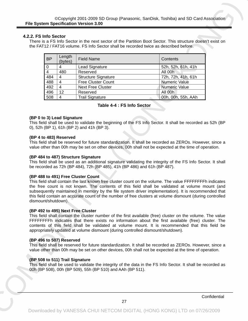
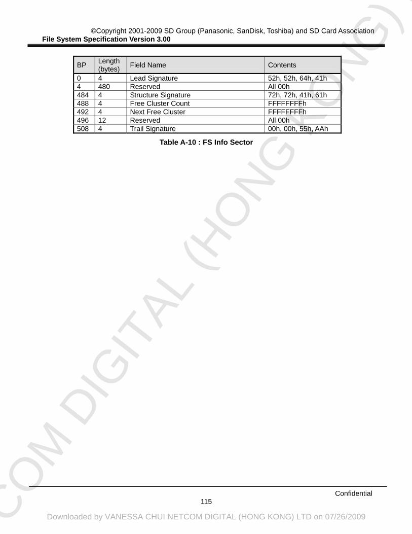
There is a FS Info Sector in the next sector of the Partition Boot Sector. This structure doesn’t exist on the FAT12 / FAT16 volume. FS Info Sector shall be recorded twice as described before.
BP Length (bytes) Field Name Contents
0 4 Lead Signature 52h, 52h, 61h, 41h 4 480 Reserved All 00h 484 4 Structure Signature 72h, 72h, 41h, 61h 488 4 Free Cluster Count Numeric Value 492 4 Next Free Cluster Numeric Value 496 12 Reserved All 00h 508 4 Trail Signature 00h, 00h, 55h, AAh
Table 4-4 : FS Info Sector
(BP 0 to 3) Lead Signature This field shall be used to validate the beginning of the FS Info Sector. It shall be recorded as 52h (BP 0), 52h (BP 1), 61h (BP 2) and 41h (BP 3).
(BP 4 to 483) Reserved This field shall be reserved for future standardization. It shall be recorded as ZEROs. However, since a value other than 00h may be set on other devices, 00h shall not be expected at the time of operation.
(BP 484 to 487) Structure Signature This field shall be used as an additional signature validating the integrity of the FS Info Sector. It shall be recorded as 72h (BP 484), 72h (BP 485), 41h (BP 486) and 61h (BP 487).
(BP 488 to 491) Free Cluster Count This field shall contain the last known free cluster count on the volume. The value FFFFFFFFh indicates the free count is not known. The contents of this field shall be validated at volume mount (and subsequently maintained in memory by the file system driver implementation). It is recommended that this field contain an accurate count of the number of free clusters at volume dismount (during controlled dismount/shutdown). (BP 492 to 495) Next Free Cluster This field shall contain the cluster number of the first available (free) cluster on the volume. The value FFFFFFFFh indicates that there exists no information about the first available (free) cluster. The contents of this field shall be validated at volume mount. It is recommended that this field be appropriately updated at volume dismount (during controlled dismount/shutdown). (BP 496 to 507) Reserved This field shall be reserved for future standardization. It shall be recorded as ZEROs. However, since a value other than 00h may be set on other devices, 00h shall not be expected at the time of operation. (BP 508 to 511) Trail Signature This field shall be used to validate the integrity of the data in the FS Info Sector. It shall be recorded as 00h (BP 508), 00h (BP 509), 55h (BP 510) and AAh (BP 511).
NETCO
M D
IGIT
AL (H
ONG
KO
NG) L
TD
Downloaded by VANESSA CHUI NETCOM DIGITAL (HONG KONG) LTD on 07/26/2009
The File Allocation Table consists of 32-bit FAT Entries. Each FAT Entry value is described in the following table. The high 4 bits of a FAT32 FAT Entry are reserved. All FAT implementations shall preserve the current value of the high 4 bits when modifying any FAT32 FAT entry except during volume initialization (formatting) when the entire FAT table shall be set to 0. And no FAT32 volume should ever be configured containing cluster numbers available for allocation >= FFFFFF7h.
FAT Entry Value
(FAT32) Contents
0000000h Indicates that the corresponding cluster is not in use and may be allocated to a file or a directory.
0000002h to MAX
Indicates that the corresponding cluster is already allocated. The value of the entry is the cluster number of the next cluster following this corresponding cluster. Max shall be the Maximum Cluster Number.
MAX+1 to FFFFFF6h
Shall be reserved for future standardization and shall not be used.
FFFFFF7h Indicates that the corresponding cluster has a defective cluster.
FFFFFF8h to FFFFFFFh
The corresponding cluster is already allocated, and it is the final cluster of the file. This entry value is called EOC mark (End Of Clusterchain).
Table 4-5 : FAT Entry Value
The first two entries (8 bytes) in the FAT are reserved. These 8 bytes of the FAT shall be recorded as F8h (BP 0), FFh (BP 1), FFh (BP 2), 0Fh (BP 3), FFh (BP 4), FFh (BP 5), FFh (BP 6) and 0Fh (BP 7). However, the file system driver may use the specific two bits of BP 7 for dirty volume flags as follows. Bit 3 (Clean Shutdown Bit) : If bit is 1, the volume is “clean”. The volume can be mounted for access.
If bit is 0, the volume is “dirty” indicating that a FAT file system driver was unable to dismount the volume properly (during a prior mount operation). The volume contents should be scanned for any damage to file system metadata.
Bit 2 (Hard Error Bit) : If bit is 1, no disk read/write errors were encountered. If bit is 0, the file system driver implementation encountered a disk I/O error on the
volume the last time it was mounted, which is an indicator that some sectors may have gone bad. The volume contents should be scanned with a disk repair utility that does surface analysis on it looking for new bad sectors.
The sectors of the FAT may include unused area, because the number of clusters shall determine the FAT size in byte. This unused area shall be recorded as ZEROs.
NETCO
M D
IGIT
AL (H
ONG
KO
NG) L
TD
Downloaded by VANESSA CHUI NETCOM DIGITAL (HONG KONG) LTD on 07/26/2009
A Directory is a Descriptor that shall contain a set of Directory entries each of which identifies a file, a Volume Label, another Directory or is unused. The maximum number of Directory entries in a Directory including root directory is 65536. The format of the file name for the Directory entries shall support 8.3 format as mandatory. And hosts can also support Long File Name (LFN) as optional. If host doesn’t support Long File Name, it may ignore Long File Name entries, and refers to only the file name of 8.3 format that is stored with the LFN.
NOTE: The Long File Name feature is described in Appendix C.3.
As described in the previous section, on FAT12 and FAT16 volumes, the root directory shall immediately follow the last file allocation table. And the size is a fixed size in sectors calculated from the Number of Root-directory Entries value stored in Partition Boot Sector. On volumes formatted FAT32, the root directory can be of variable size. The location of the first cluster of the root directory on the FAT32 volume is stored in the Root Cluster field of Partition Boot Sector. Only the root directory can contain a Volume Label Entry. There is no name for the root directory (on most operating system implementations, the implied name “\” is used). Further, the root directory does not have any associated date/time stamps. Lastly, the root directory does not contain either the dot and dotdot entries.
4.2.4.2. Directory Entry Fields
The following table indicates the structure of the Directory entry field.
BP Length (bytes) Field Name Contents
0 11 Name and Name Extension bytes 11 1 Attributes 8 bits 12 1 Reserved for NT byte 13 1 Created Time Tenth Numeric Value 14 2 Created Time Numeric Value 16 2 Created Date Numeric Value 18 2 Last Access Date Numeric Value 20 2 Starting Cluster Number High Numeric Value 22 2 Time Recorded Numeric Value 24 2 Date Recorded Numeric Value 26 2 Starting Cluster Number Low Numeric Value 28 4 File Length Numeric Value
Table 4-6 : Directory Entry Field
(BP 0 to 10) Name and Name Extension This field shall contain the 11 character (“short”) name of the file or sub-directory described by the corresponding entry containing the field. This field is logically comprised of two components:
The 8-character man part of the name The 3-character extension
Each of the above two components are “trailing space padded” if required (using value: 20h).
NETCO
M D
IGIT
AL (H
ONG
KO
NG) L
TD
Downloaded by VANESSA CHUI NETCOM DIGITAL (HONG KONG) LTD on 07/26/2009
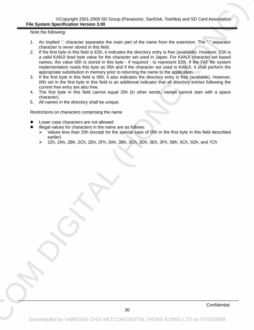
Note the following: 1. An implied ‘.’ character separates the main part of the name from the extension. The “.” separator
character is never stored in this field. 2. If the first byte in this field is E5h, it indicates the directory entry is free (available). However, E5h is
a valid KANJI lead byte value for the character set used in Japan. For KANJI character set based names, the value 05h is stored in this byte - if required - to represent E5h. If the FAT file system implementation reads this byte as 05h and if the character set used is KANJI, it shall perform the appropriate substitution in memory prior to returning the name to the application.
3. If the first byte in this field is 00h, it also indicates the directory entry is free (available). However, 00h set in the first byte in this field is an additional indicator that all directory entries following the current free entry are also free.
4. The first byte in this field cannot equal 20h (in other words, names cannot start with a space character).
5. All names in the directory shall be unique. Restrictions on characters comprising the name
Lower case characters are not allowed Illegal values for characters in the name are as follows:
Values less than 20h (except for the special case of 05h in the first byte in this field described earlier)
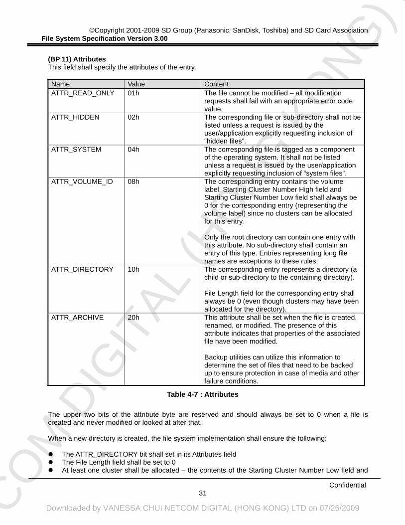
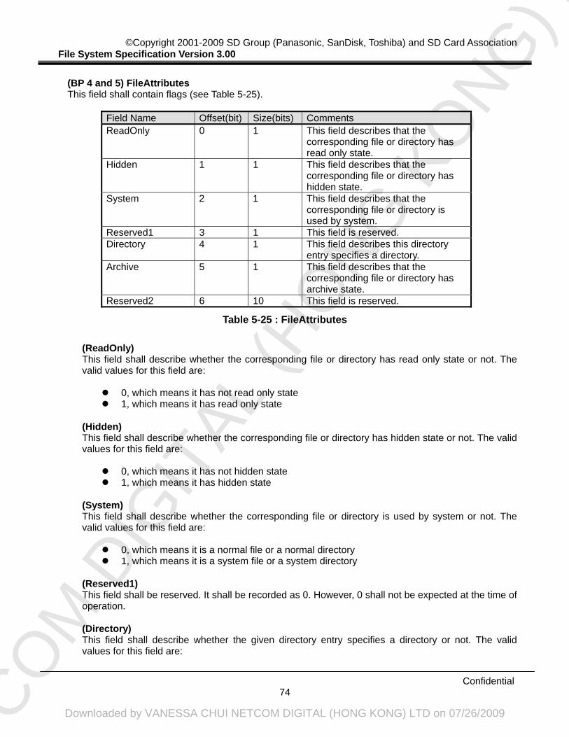
(BP 11) Attributes This field shall specify the attributes of the entry.
Name Value Content ATTR_READ_ONLY 01h The file cannot be modified – all modification
requests shall fail with an appropriate error code value.
ATTR_HIDDEN 02h The corresponding file or sub-directory shall not be listed unless a request is issued by the user/application explicitly requesting inclusion of “hidden files”.
ATTR_SYSTEM 04h The corresponding file is tagged as a component of the operating system. It shall not be listed unless a request is issued by the user/application explicitly requesting inclusion of “system files”.
ATTR_VOLUME_ID 08h The corresponding entry contains the volume label. Starting Cluster Number High field and Starting Cluster Number Low field shall always be 0 for the corresponding entry (representing the volume label) since no clusters can be allocated for this entry. Only the root directory can contain one entry with this attribute. No sub-directory shall contain an entry of this type. Entries representing long file names are exceptions to these rules.
ATTR_DIRECTORY 10h The corresponding entry represents a directory (a child or sub-directory to the containing directory). File Length field for the corresponding entry shall always be 0 (even though clusters may have been allocated for the directory).
ATTR_ARCHIVE 20h This attribute shall be set when the file is created, renamed, or modified. The presence of this attribute indicates that properties of the associated file have been modified. Backup utilities can utilize this information to determine the set of files that need to be backed up to ensure protection in case of media and other failure conditions.
Table 4-7 : Attributes
The upper two bits of the attribute byte are reserved and should always be set to 0 when a file is created and never modified or looked at after that. When a new directory is created, the file system implementation shall ensure the following:
The ATTR_DIRECTORY bit shall set in its Attributes field The File Length field shall be set to 0 At least one cluster shall be allocated – the contents of the Starting Cluster Number Low field and
NETCO
M D
IGIT
AL (H
ONG
KO
NG) L
TD
Downloaded by VANESSA CHUI NETCOM DIGITAL (HONG KONG) LTD on 07/26/2009
Starting Cluster Number High field shall refer to the first allocated cluster number If only a single cluster is allocated, the corresponding file allocation table entry shall indicate end-of-
file condition The contents of the allocated cluster(s) shall be initialized to 0 Except for the root directory, each directory shall contain the following two entries at the beginning
of the directory:
The first directory entry shall have a directory name set to “.”
This dot entry refers to the current directory. Rules listed above for the Attributes field and File Length field shall be followed. Since the dot entry refers to the current directory (the one containing the dot entry), the contents of the Starting Cluster Number Low field and Starting Cluster Number High field shall be the same as that of the current directory. All date and time fields shall be set to the same value as that for the containing directory.
The second directory entry shall have the directory name set to “..”
This dotdot entry refers to the parent of the current directory. Rules listed above for the Attributes field and File Length field shall be followed. Since the dotdot entry refers to the parent of the current directory (the one containing the dotdot entry), the contents of the Starting Cluster Number Low field and Starting Cluster Number High field shall be the same as that of the parent of the current directory. If the parent of the current directory is the root directory, the Starting Cluster Number Low field and Starting Cluster Number High field contents shall be set to 0. All date and time fields shall be set to the same value as that for the containing directory.
(BP 12) Reserved for NT This field shall be reserved. This field shall be set to 0. (BP 13) Created Time Tenth This field shall specify the component of the file creation time. This field actually contains a count of tenths of a second. The valid value range is 0-199 inclusive. If this field is not supported, it should be set to 0 on file create and ignored on other file operations. (BP 14 and 15) Created Time This field shall specify the file creation time. The detailed format is described in the following section. If this field is not supported, it should be set to 0 on file create and ignored on other file operations. (BP 16 and 17) Created Date This field shall specify the file creation date. The detailed format is described in the following section. If this field is not supported, it should be set to 0 on file create and ignored on other file operations. (BP 18 and 19) Last Access Date This field shall specify the last access date. Last access is defined as a read or write operation performed on the file/directory described by this entry. This field shall be updated on file modification (write operation) and the date value shall be equal to Date Recorded field. The detailed format is described in the following section. If this field is not supported, it should be set to 0 on file create and ignored on other file operations. (BP 20 and 21) Starting Cluster Number High This field shall specify the high word of first data cluster number for file/directory described by this entry. (BP 22 and 23) Time Recorded
NETCO
M D
IGIT
AL (H
ONG
KO
NG) L
TD
Downloaded by VANESSA CHUI NETCOM DIGITAL (HONG KONG) LTD on 07/26/2009
This field shall specify the last modification (write) time. This field shall be equal to Created Time field at file creation. The detailed format is described in the following section. This field shall be supported by all hosts. (BP 24 and 25) Date Recorded This field shall specify the last modification (write) date. This field shall be equal to Created Date field at file creation. The detailed format is described in the following section. This field shall be supported by all hosts. (BP 26 and 27) Starting Cluster Number Low This field shall specify the low word of first data cluster number for file/directory described by this entry. (BP 28 to 31) File Length This field shall specify the 32-bit quantity containing size in bytes of file/directory described by this entry.
4.2.4.3. Date and Time Formats
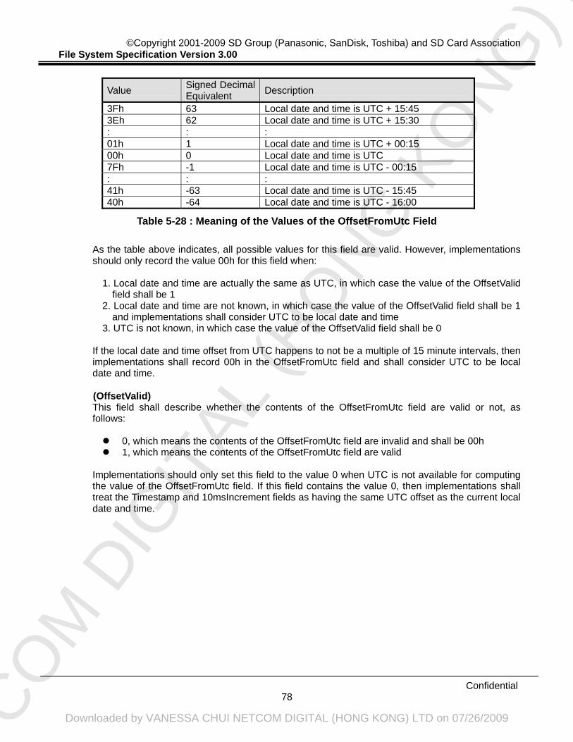
The date and time formats in the directory entry are as follows.
(Date Format) Contents of the date related field in the directory entry shall be in the following format:
Bit positions 0 through 4 represent the day of the month (valid range: 1..31 inclusive) Bit positions 5 through 8 represent the month of the year (1 = January, 12 = December, valid
range: 1..12 inclusive) Bit positions 9 through 15 are the count of years from 1980 (valid range: 0..127 inclusive
allowing representation of years 1980 through 2107) (Time Format) Directory entry timestamps are 16-bit values with a granularity of 2 seconds. Contents of the timerelated field in the directory entry shall be in the following format:
Bit positions 0 through 4 contain elapsed seconds – as a count of 2-second increments (valid range: 0..29 inclusive allowing representation of 0 through 58 seconds)
Bit positions 5 through 10 represent number of minutes (valid range: 0..59 inclusive) Bit positions 11 through 15 represent hours (valid range: 0..23 inclusive)
The valid time range is from Midnight 00:00:00 to 23:59:58.
4.2.4.4. Difference from the FAT12 / FAT16 File Directories
File directories of FAT32 file system are similar to FAT12 / FAT16 file system (ISO/IEC 9293), however there are some differences. The main differences between them are as follows:
For FAT32, the root directory isn’t located in the special location, and it can be of variable size and is a cluster chain, just like any other directory is.
The following fields in the directory entry are added : Reserved for NT, Created Time Tenth, Created Time, Created Date, Last Access Date, and Starting Cluster Number High
4.2.4.5. User Area
The User Area shall consist of some clusters. Each cluster has a Cluster Number respectively. The first cluster in the User Area is corresponding to Cluster Number 2. Although it is available to read/write by the sector, it is recommended to transact reading/writing with the unit whose minimum size is the same as that of the recommended reading/writing at the physical layer. Other than that, there are no special restrictions for the SD Memory Card file system.
NETCO
M D
IGIT
AL (H
ONG
KO
NG) L
TD
Downloaded by VANESSA CHUI NETCOM DIGITAL (HONG KONG) LTD on 07/26/2009
The volume structure of the Extended Capacity SD Memory Card is specified in this section. For the identification of the Data Area as a partition, Master Boot Record and Partition Table exist in the first sector of the card as well as the Standard Capacity SD Memory Card. The exFAT file system shall be applied to the Extended Capacity SD Memory Card.
NOTE: exFAT Specification described in this section includes portions of “exFAT Revision 1.00
File System Basic Specification”, the copyright of which is owned by Microsoft but licensed to SD Card Association.
Figure 5-1 : Example of Volume Structure for Data Area 5.1.1. Arrangement of the Data Area
The arrangement of the Data Area for Extended Capacity SD Memory Card is the same one with the arrangement for the Standard Capacity SD Memory Card. That is, this type of the card has the concept of Physical Address, Physical Sector Number and Logical Sector Number, and Data Area is divided into the Partition Area and the Regular Area too. The detailed explanation is described in the section “3.1.1. Arrangement of the Data Area”.
5.1.2. Arrangement of the User Area
The arrangement of the User Area for Extended Capacity SD Memory Card is the same one with the arrangement for the Standard Capacity SD Memory Card.
LSN : Logical Sector Number PSN : Physical Sector Number
File Allocation Table
User Data (Cluster Heap)
File System Layout
Boot Region
Master Boot Record and Partition Table
PSN
0 to 32767
32768 to 49151
49152 to 65535
65536 to 133955583
LSN
0 to 16383
16384 to 32767
32768 to 133922815
Regular Area
Partition Area
System Area
User Area
(sector)
NETCO
M D
IGIT
AL (H
ONG
KO
NG) L
TD
Downloaded by VANESSA CHUI NETCOM DIGITAL (HONG KONG) LTD on 07/26/2009
That is, the User Area shall be organized into units of Cluster, and there are three statuses for Cluster. The detailed explanation is described in the section “3.1.2. Arrangement of the User Area”.
Moreover, in the exFAT Specification, this area is called as “Cluster Heap”. Therefore, this section may use the words “Cluster Heap” instead of the words “User Data Area”. Note that these are the same meaning.
5.1.3. Arrangement of the Partition Area
The first sector of the Data Area has a Master Boot Record that includes executable codes and Partition Table that includes the information to identify the partition as well as the Standard Capacity SD Memory Card.
BP Length (bytes) Field Name Contents
0 446 Master Boot Record Not Restricted 446 16 Partition Table (partition1) Refer to Table 5-2 462 16 Partition Table (partition2) All 00h 478 16 Partition Table (partition3) All 00h 494 16 Partition Table (partition4) All 00h 510 2 Signature Word 55h, AAh
Table 5-1 : Master Boot Record and Partition Table
(BP 0 to 445) Master Boot Record The content of this field is not specified by this specification.
(BP 446 to 461) Partition Table (partition1) This field shall specify the information of first partition in the volume. This partition means Regular Area that user can access without mutual authentication. It shall be recorded according to Table 5-2.
(BP 462 to 477) Partition Table (partition2) This field shall be recorded as ZEROs, as a volume shall consist of single Regular Area.
(BP 478 to 493) Partition Table (partition3) This field shall be recorded as ZEROs, as a volume shall consist of single Regular Area.
(BP 494 to 509) Partition Table (partition4) This field shall be recorded as ZEROs, as a volume shall consist of single Regular Area.
(BP 510 and 511) Signature Word This field shall be recorded as 55h (BP 510) and AAh (BP 511).
NETCO
M D
IGIT
AL (H
ONG
KO
NG) L
TD
Downloaded by VANESSA CHUI NETCOM DIGITAL (HONG KONG) LTD on 07/26/2009
0 1 Boot Indicator 00h or 80h 1 1 Starting Head Numeric Value 2 2 Starting Sector / Starting Cylinder Numeric Value 4 1 System ID 07h 5 1 Ending Head FEh 6 2 Ending Sector / Ending Cylinder FFFFh 8 4 Relative Sector Numeric Value 12 4 Total Sector Numeric Value
Table 5-2 : Partition Table
(BP 0) Boot Indicator This field shall be recorded as 80h if SD Memory Card is used for boot. Otherwise, this field shall be recorded as 00h.
(BP 1) Starting Head This field shall specify the starting head of the partition. If the starting location of the partition exceeds 8032.5MB (8,422,686,720Bytes), this field shall be recorded as FEh.
(BP 2 and 3) Starting Sector / Starting Cylinder This field shall specify the starting sector and cylinder of the partition. 6 bits (Bit 0 to Bit 5 in BP 2) in this field shall be used for starting sector. 10 bits (Bit 6 and Bit 7 in BP 2, Bit 0 to Bit 7 in BP 3) in this field shall be used for starting cylinder. If the starting location of the partition exceeds 8032.5MB (8,422,686,720Bytes), this field shall be recorded as FFFFh.
(BP 4) System ID This field shall be recorded as 07h.
(BP 5) Ending Head This field shall specify the ending head of the partition. However, in case of the Extended Capacity SD Memory Card, this field shall not be used for the recognition of the ending location. This field shall be recorded as FEh.
(BP 6 and 7) Ending Sector / Ending Cylinder This field shall specify the ending sector and cylinder of the partition. 6 bits (Bit 0 to Bit 5 in BP 6) in this field shall be used for ending sector. 10 bits (Bit 6 and Bit 7 in BP 6, Bit 0 to Bit 7 in BP 7) in this field shall be used for ending cylinder. However, in case of the Extended Capacity SD Memory Card, this field shall not be used for the recognition of the ending location. This field shall be recorded as FFFFh.
(BP 8 to 11) Relative Sector This field shall specify the number of sectors existing before the starting sector of this partition. The starting sector of the partition should be aligned to the Boundary Unit specified in Appendix C.5. Detailed explanations for the alignment are described in Appendix C.5.
(BP 12 to 15) Total Sector This field shall specify the number of sectors on the partition.
NETCO
M D
IGIT
AL (H
ONG
KO
NG) L
TD
Downloaded by VANESSA CHUI NETCOM DIGITAL (HONG KONG) LTD on 07/26/2009
5.1.4. Arrangement of the System Area 5.1.4.1. System Area
The System Area shall contain two Boot Regions (Main Boot region and Backup Boot region) and the File Allocation Table (FAT). The Backup Boot region is a backup of the Main Boot region. It aids recovery of the exFAT volume in the advent of the Main Boot region being in an inconsistent state. Except under infrequent circumstances, such as updating boot-strapping instructions, implementations should not modify the contents of the Backup Boot region.
5.1.4.2. Main and Backup Boot Region
Both Boot Regions consist from 12 sectors each. The first sector shall contain the Boot Sector. It shall contain the parameters for the partition like cluster size, partition size, etc. From the second sector to the ninth sector shall contain the Extended Boot Sectors. It may contain the boot-strapping instructions. The tenth sector shall contain the OEM Parameters. It may contain manufacturer-specific information. The eleventh sector shall be reserved. This sector shall be recorded as ZEROs. However, 00h shall not be expected at the time of operation. The twelfth sector shall contain the Boot Checksum. It shall contain a repeating pattern of the four-byte checksum of the contents of all other sectors in Boot Region. These 24 sectors shall be recorded in the first 24 sectors of the partition as follows.
NETCO
M D
IGIT
AL (H
ONG
KO
NG) L
TD
Downloaded by VANESSA CHUI NETCOM DIGITAL (HONG KONG) LTD on 07/26/2009
Figure 5-2 : System Area Layout 5.1.4.3. File Allocation Table (FAT)
The FAT shall contain a Format Identifier and some entries, each of which indicates cluster of the Cluster Heap. These entries shall be numbered consecutively starting with 2 and the Entry Number shall be equal to the Cluster Number of the corresponding cluster. In an exFAT volume, a FAT maintains only the cluster chain information and an Allocation Bitmap maintains the record of the allocation state of all clusters. This is a significant difference from exFAT's predecessors (FAT12, FAT16, and FAT32), in which a FAT maintained both the cluster chain information and the record of the allocation state of all clusters.
M : The number of FatOffset N : The number of FatLength
Main Extended Boot Sectors
Main Boot SectorLSN
0
Main OEM Parameters9
1 to 8
System Area Layout
Reserved (Not specified in this specification)
Main Reserved11 Main Boot Checksum
24 to (M-24)
File Allocation Table M to (M+N-1)
Backup
(sector)
10
Backup Extended Boot Sectors
Backup Boot Sector12
Backup OEM Parameters21
13 to 20
Backup Reserved
23 Backup Boot Checksum
22
NETCO
M D
IGIT
AL (H
ONG
KO
NG) L
TD
Downloaded by VANESSA CHUI NETCOM DIGITAL (HONG KONG) LTD on 07/26/2009
5.2. File Structure 5.2.1. Main and Backup Boot Sector
The Main Boot Sector contains code for boot-strapping from an exFAT volume and fundamental exFAT parameters which describe the volume structure. BIOS, MBR, or other boot-strapping agents may inspect this sector and may load and execute any boot-strapping instructions contained therein. The Backup Boot Sector is a backup of the Main Boot Sector and has the same structure (see Table 5-3). The Backup Boot Sector may aid recovery operations; however, implementations shall treat the contents of the VolumeFlags and PercentInUse fields as stale. Prior to using the contents of either the Main or Backup Boot Sector, implementations shall verify their contents by validating their respective Boot Checksum and ensuring all their fields are within their valid value range. While the initial format operation will initialize the contents of both the Main and Backup Boot Sectors, implementations may update these sectors (and shall also update their respective Boot Checksum) as needed. However, implementations may update either the VolumeFlags or PercentInUse fields without updating their respective Boot Checksum (the checksum specifically excludes these two fields).
BP Length (bytes) Field Name Contents
0 3 JumpBoot EBh, 76h, 90h 3 8 FileSystemName “EXFAT “ 11 53 MustBeZero All 00h 64 8 PartitionOffset Numeric Value 72 8 VolumeLength Numeric Value 80 4 FatOffset Numeric Value 84 4 FatLength Numeric Value 88 4 ClusterHeapOffset Numeric Value 92 4 ClusterCount Numeric Value 96 4 FirstClusterOfRootDirectory Numeric Value 100 4 VolumeSerialNumber Numeric Value 104 2 FileSystemRevision Numeric Value 106 2 VolumeFlags Numeric Value 108 1 BytesPerSectorShift Numeric Value 109 1 SectorsPerClusterShift Numeric Value 110 1 NumberOfFats Numeric Value 111 1 DriveSelect 80h 112 1 PercentInUse Numeric Value 113 7 Reserved All 00h 120 390 BootCode Not Restricted 510 2 BootSignature 55h, AAh
Table 5-3 : Main and Backup Boot Sector
(BP 0 to 2) JumpBoot This field shall specify the jump instruction for CPUs common in personal computers, which, when executed, “jumps” the CPU to execute the boot-strapping instructions in the BootCode field. It shall be recorded as EBh (BP 0), 76h (BP 1) and 90h (BP 2).
NETCO
M D
IGIT
AL (H
ONG
KO
NG) L
TD
Downloaded by VANESSA CHUI NETCOM DIGITAL (HONG KONG) LTD on 07/26/2009
(BP 3 to 10) FileSystemName This field shall specify the name of the file system on the volume. It shall be recorded as, in ASCII characters, “EXFAT ”, which includes three trailing white spaces.
(BP 11 to 63) MustBeZero This field directly corresponds with the range of bytes the packed Partition Boot Sector consumes on FAT12/16/32 volumes. It shall be recorded as ZEROs, which helps to prevent FAT12/16/32 implementations from mistakenly mounting an exFAT volume.
(BP 64 to 71) PartitionOffset This field shall specify the number of sectors existing before the starting sector of this partition. The starting sector of the partition should be aligned to the Boundary Unit specified in Appendix C.5. Detailed explanations for the alignment are described in Appendix C.5.
(BP 72 to 79) VolumeLength This field shall specify the number of sectors on the partition.
(BP 80 to 83) FatOffset This field shall specify the volume-relative sector offset of the First FAT. That is, this field shall specify the number of sectors existing from the Main Boot Sector to the First FAT. This field enables implementations to align the First FAT to the characteristics of the card. The starting sector of the First FAT should be aligned complying with the alignment rule described in this specification. Detailed explanations for the alignment are described in Appendix C.5.
(BP 84 to 87) FatLength This field shall specify the length, in sectors, of each FAT table (the volume may contain up to two FATs). This field may contain a value in excess of its lower bound (the minimum FAT size which ensures each FAT has sufficient space for describing all the clusters in the Cluster Heap) to enable the Second FAT, if present, to also be aligned to the characteristics of the underlying storage media. The contents of space which exceeds what the FAT itself requires, if any, are undefined. The FAT size should be the half size of the Boundary Unit in order to comply with the alignment rule described in this specification. Detailed explanations for the alignment are described in Appendix C.5. (BP 88 to 91) ClusterHeapOffset This field shall specify the volume-relative sector offset of the Cluster Heap. That is, this field shall specify the number of sectors existing from the Main Boot Sector to the starting sector of the Cluster Heap. This field enables implementations to align the Cluster Heap to the characteristics of the card. The starting sector of the Cluster Heap should be aligned to the Boundary Unit specified in Appendix C.5. Detailed explanations for the alignment are described in Appendix C.5. (BP 92 to 95) ClusterCount This field shall specify the number of clusters the Cluster Heap contains. (BP 96 to 99) FirstClusterOfRootDirectory This field shall specify the cluster index of the first cluster of the root directory. Implementations should make every effort to place the first cluster of the root directory in the first non-bad cluster after the clusters the Allocation Bitmap and Up-case Table consume. (BP 100 to 103) VolumeSerialNumber This field shall specify a unique serial number. This assists implementations to distinguish among different exFAT volumes. Implementations should generate the serial number by combining the date and time of formatting the exFAT volume. The mechanism for combining date and time to form a serial number is implementation-specific.
NETCO
M D
IGIT
AL (H
ONG
KO
NG) L
TD
Downloaded by VANESSA CHUI NETCOM DIGITAL (HONG KONG) LTD on 07/26/2009
(BP 104 and 105) FileSystemRevision This field shall specify the major and minor revision numbers of the exFAT structures on the given volume. The high-order byte is the major revision number and the low-order byte is the minor revision number. For example, if the high-order byte contains the value 01h and if the low-order byte contains the value 05h, then the FileSystemRevision field describes the revision number 1.05. Likewise, if the high-order byte contains the value 0Ah and if the low-order byte contains the value 0Fh, then the FileSystemRevision field describes the revision number 10.15. The maximum value of each byte is 63h. This means the maximum revision numbers are 99.99. This field shall be recorded as 00h (BP 104) and 01h (BP 105). This describes the revision number 1.00. Implementations of this specification should mount any exFAT volume with major revision number 1 and shall not mount any exFAT volume with any other major revision number. Implementations shall honor the minor revision number and shall not perform operations or create any file system structures not described in the given minor revision number’s corresponding specification. (BP 106 and 107) VolumeFlags This field shall be used to contain flags which indicate the status of various file system structures on the exFAT volume (see Table 5-4). Implementations shall not include this field when computing its respective Main Boot or Backup Boot region checksum. When referring to the Backup Boot Sector, implementations shall treat this field as stale.
Field Name Offset(bit) Size(bits) Comments ActiveFat 0 1 This field describes which FAT and
Allocation Bitmap are active. VolumeDirty 1 1 This field describes whether the
volume is dirty or not. MediaFailure 2 1 This field describes whether an
implementation has discovered media failures or not.
ClearToZero 3 1 This field does not have significant meaning in this specification.
Reserved 4 12 This field is reserved.
Table 5-4 : VolumeFlags
(ActiveFat) This field shall describe which FAT and Allocation Bitmap are active (and implementations shall use), as follows:
0, which means the First FAT and First Allocation Bitmap are active 1, which means the Second FAT and Second Allocation Bitmap are active and is possible
only when the NumberOfFats field contains the value 2 Implementations shall consider the inactive FAT and Allocation Bitmap as stale. (VolumeDirty) This field shall describe whether the volume is dirty or not, as follows:
0, which means the volume is probably in a consistent state 1, which means the volume is probably in an inconsistent state
Implementations should set the value of this field to 1 upon encountering file system metadata
NETCO
M D
IGIT
AL (H
ONG
KO
NG) L
TD
Downloaded by VANESSA CHUI NETCOM DIGITAL (HONG KONG) LTD on 07/26/2009
inconsistencies which they do not resolve. If, upon mounting a volume, the value of this field is 1, only implementations which resolve file system metadata inconsistencies may clear the value of this field to 0. Such implementations shall only clear the value of this field to 0 after ensuring the file system is in a consistent state. If, upon mounting a volume, the value of this field is 0, implementations should set this field to 1 before updating file system metadata and clear this field to 0 afterwards, similar to the recommended write ordering Section 5.2.9.1 describes. (MediaFailure) This field shall describe whether an implementation has discovered media failures or not, as follows:
0, which means the hosting media has not reported failures or any known failures are already recorded in the FAT as “bad” clusters
1, which means the hosting media has reported failures (i.e. has failed read or write operations)
An implementation should set this field to 1 when:
1. The hosting media fails access attempts to any region in the volume 2. The implementation has exhausted access retry algorithms, if any
If, upon mounting a volume, the value of this field is 1, implementations which scan the entire volume for media failures and record all failures as “bad” clusters in the FAT (or otherwise resolve media failures) may clear the value of this field to 0. (ClearToZero) This field shall not have significant meaning in this specification. The valid values for this field are:
0, which does not have any particular meaning 1, which means implementations shall clear this field to 0 prior to modifying any file system
structures, directories, or files
(Reserved) This field shall be reserved. It shall be recorded as ZEROs. However, 00h shall not be expected at the time of operation.
(BP 108) BytesPerSectorShift This field shall specify the bytes per sector expressed as log2(N), where N is the number of bytes per sector. For example, for 512 bytes per sector, the value of this field is 9. This field shall be recorded as the number 9. (BP 109) SectorsPerClusterShift This field shall specify the sectors per cluster expressed as log2(N), where N is the number of sectors per cluster. For example, for 8 sectors per cluster, the value of this field is 3. The valid range of this field shall be from 0 to 16. This means the minimum cluster size is 512 bytes and the maximum cluster size is 32MB. And the cluster size shall be determined taking the erase block size of physical layer into account. This field should be recorded complying with the recommendation of this specification. Detailed explanations for the recommendation are described in Appendix C.5. (BP 110) NumberOfFats This field shall specify the number of FATs and Allocation Bitmaps the volume contains. It shall be recorded as the number 1 or 2. However, 1 should be used by default. If this field is recorded as the number 2, the inactive FAT and Allocation Bitmap shall be ignored by the host which supports only one FAT.
NETCO
M D
IGIT
AL (H
ONG
KO
NG) L
TD
Downloaded by VANESSA CHUI NETCOM DIGITAL (HONG KONG) LTD on 07/26/2009
(BP 111) DriveSelect This field shall specify the extended INT 13h drive number, which aids boot-strapping from this volume using extended INT 13h on personal computers. It shall be recorded as 80h. (BP 112) PercentInUse This field shall specify the percentage of clusters in the Cluster Heap which are allocated. The valid range of values for this field is:
Between 0 and 100 inclusively, which is the percentage of allocated clusters in the Cluster Heap, rounded down to the nearest integer Exactly FFh, which indicates the percentage of allocated clusters in the Cluster Heap is not available
Implementations shall change the value of this field to reflect changes in the allocation of clusters in the Cluster Heap or shall change it to FFh. Implementations shall not include this field when computing its respective Main Boot or Backup Boot region checksum. When referring to the Backup Boot Sector, implementations shall treat this field as stale. (BP 113 to 119) Reserved This field shall be reserved for future standardization. It shall be recorded as ZEROs. However, 00h shall not be expected at the time of operation. (BP 120 to 509) BootCode This field shall be used to contain boot-strapping instructions. Implementations may populate this field with the CPU instructions necessary for boot-strapping a computer system. Implementations which don’t provide boot-strapping instructions shall initialize each byte in this field to F4h as part of their format operation. (BP 510 and 511) BootSignature This field shall describe whether the intent of given sector is for it to be a Boot Sector or not. It shall be recorded as 55h (BP 510) and AAh (BP 511). Any other value in this field invalidates its respective Boot Sector. Implementations should verify the contents of this field prior to depending on any other field in its respective Boot Sector.
NETCO
M D
IGIT
AL (H
ONG
KO
NG) L
TD
Downloaded by VANESSA CHUI NETCOM DIGITAL (HONG KONG) LTD on 07/26/2009
Each sector of the Main Extended Boot Sectors has the same structure; however, each sector may hold distinct boot-strapping instructions (see Table 5-5). Boot-strapping agents, such as the boot-strapping instructions in the Main Boot Sector, alternate BIOS implementations, or an embedded system’s firmware, may load these sectors and execute the instructions they contain. The Backup Extended Boot Sectors is a backup of the Main Extended Boot Sectors and has the same structure (see Table 5-5). Prior to executing the instructions of either the Main or Backup Extended Boot Sectors, implementations should verify their contents by ensuring each sector’s ExtendedBootSignature field contains its prescribed value. While the initial format operation will initialize the contents of both the Main and Backup Extended Boot Sectors, implementations may update these sectors (and shall also update their respective Boot Checksum) as needed.
(BP 0 to 507) ExtendedBootCode This field shall be used to contain boot-strapping instructions. Implementations may populate this field with the CPU instructions necessary for boot-strapping a computer system. Implementations which don’t provide boot-strapping instructions shall initialize each byte in this field to 00h as part of their format operation. (BP 508 to 511) ExtendedBootSignature This filed shall describe whether the intent of given sector is for it to be an Extended Boot Sector or not. It shall be recorded as 00h (BP 508), 00h (BP 509), 55h (BP 510) and AAh (BP 511). Any other value in this field invalidates its respective Main or Backup Extended Boot Sector. Implementations should verify the contents of this field prior to depending on any other field in its respective Extended Boot Sector.
NETCO
M D
IGIT
AL (H
ONG
KO
NG) L
TD
Downloaded by VANESSA CHUI NETCOM DIGITAL (HONG KONG) LTD on 07/26/2009
The Main OEM Parameters contains ten parameters structures which contain manufacturer-specific information (see Table 5-6). Each of the ten parameters structures derives from the Generic Parameters template (see Section 5.2.3.2). Manufacturers may derive their own custom parameters structures from the Generic Parameters template. This specification itself defines two parameters structures: Null Parameters (see Section 5.2.3.3) and Flash Parameters (see Section 5.2.3.4). The Backup OEM Parameters is a backup of the Main OEM Parameters and has the same structure (see Table 5-6). Prior to using the contents of either the Main or Backup OEM Parameters, implementations shall verify their contents by validating their respective Boot Checksum. Manufacturers should populate the Main and Backup OEM Parameters with their own custom parameters structures, if any, and any other parameter structures. Subsequent format operations shall preserve the contents of the Main and Backup OEM Parameters. Implementations may update the Main and Backup OEM Parameters as needed (and shall also update their respective Boot Checksum).
Table 5-6 : Main and Backup OEM Parameters 5.2.3.1. Parameters[0] … Parameters[9]
Each Parameters field in this array contains a parameters structure, which derives from the Generic Parameters template (see Section 5.2.3.2). Any unused Parameters field shall be described as containing a Null Parameters structure (see Section 5.2.3.3).
5.2.3.2. Generic Parameters Template
The Generic Parameters template provides the base definition of a parameters structure (see Table 5-7). All parameters structures derive from this template.
BP Length (bytes) Field Name Contents
0 16 ParametersGuid GUID 16 32 CustomDefined Not Restricted
Table 5-7 : Generic Parameters Template
(BP 0 to 15) ParametersGuid This field shall describe a GUID, which determines the layout of the remainder of the given parameters structure. All possible values for this field are valid. (BP 16 to 31) CustomDefined The content of this field shall be defined by the structures which derive from this template.
NETCO
M D
IGIT
AL (H
ONG
KO
NG) L
TD
Downloaded by VANESSA CHUI NETCOM DIGITAL (HONG KONG) LTD on 07/26/2009
5.2.3.3. Null Parameters The Null Parameters structure derives from the Generic Parameters template (see Section 5.2.3.2) and describes an unused Parameters field (see Table 5-8). When creating or updating the OEM Parameters structure, implementations shall populate unused Parameters fields with the Null Parameters structure. Also, when creating or updating the OEM Parameters structure, implementations should consolidate Null Parameters structures at the end of the array, thereby leaving all other Parameters structures at the beginning of the OEM Parameters structure.
BP Length (bytes) Field Name Contents
0 16 ParametersGuid GUID 16 32 Reserved All 00h
Table 5-8 : Null Parameters (BP 0 to 15) ParametersGuid This field shall conform to the definition the Generic Parameters template provides (see Section 5.2.3.2). This field shall be recorded, in GUID notation, as {00000000-0000-0000-0000-000000000000}.
(BP 16 to 47) Reserved This field shall be reserved. It shall be recorded as ZEROs. However, 00h shall not be expected at the time of operation.
5.2.3.4. Flash Parameters
The Flash Parameter structure derives from the Generic Parameters template (see Section 5.2.3.2) and contains parameters of flash media (see Table 5-9). Card manufacturers should set this structure in the OEM Parameters area (preferably the Parameters[0] field). Note: This structure is used for the Cluster Heap alignment described in this specification. Therefore, this structure may not store the actual flash parameters of the card.
The value 0 indicates the field is actually meaningless (implementations shall ignore the given field).
(BP 0 to 15) ParametersGuid This field shall conform to the definition the Generic Parameters template provides (see Section 5.2.3.2). This field shall be recorded, in GUID notation, as {0A0C7E46-3399-4021-90C8-FA6D389C4BA2}. (BP 16 to 19) EraseBlockSize
NETCO
M D
IGIT
AL (H
ONG
KO
NG) L
TD
Downloaded by VANESSA CHUI NETCOM DIGITAL (HONG KONG) LTD on 07/26/2009
Basically, this field describes the size, in bytes, of the flash media’s erase block. However, the half of the Boundary Unit size, in bytes, shall be stored in this field. For example, if the Boundary Unit size is 16MB, this field shall be recorded as the number 8,388,608. (BP 20 to 23) PageSize Basically, this field describes the size, in bytes of the flash media’s page. However, this field shall be recorded as the number 0. (BP 24 to 27) SpareSectors Basically, this field describes the number of sectors the flash media has available for its internal sparing operations. However, this field shall be recorded as the number 0. (BP 28 to 31) RandomAccessTime Basically, this field describes the flash media’s average random access time, in nanoseconds. However, this field shall be recorded as the number 0. (BP 32 to 35) ProgrammingTime Basically, this field describes the flash media’s average programming time, in nanoseconds. However, this field shall be recorded as the number 0. (BP 36 to 39) ReadCycle Basically, this field describes the flash media’s average read cycle time, in nanoseconds. However, this field shall be recorded as the number 0. (BP 40 to 43) WriteCycle Basically, this field describes the average write cycle time, in nanoseconds. However, this field shall be recorded as the number 0. (BP 44 to 47) Reserved This field shall be reserved. It shall be recorded as ZEROs. However, 00h shall not be expected at the time of operation.
NETCO
M D
IGIT
AL (H
ONG
KO
NG) L
TD
Downloaded by VANESSA CHUI NETCOM DIGITAL (HONG KONG) LTD on 07/26/2009
The Main and Backup Boot Checksum contain a repeating pattern of the four-byte checksum of the contents of all other sectors in their respective Boot regions. The checksum calculation does not include the VolumeFlags and PercentInUse fields in their respective Boot Sector. The repeating pattern of the four-byte checksum fills its respective Boot Checksum from the beginning to the end of the sector. Prior to using the contents of any of the other sectors in either the Main or Backup Boot regions, implementations shall verify their contents by validating their respective Boot Checksum. While the initial format operation will populate both the Main and Backup Boot Checksums with the repeating checksum pattern, implementations shall update these sectors as the contents of the other sectors in their respective Boot regions change. The below algorithm describes the logic used to generate the checksum value:
UInt32 BootChecksum (
UCHAR * Sectors, // points to an in-memory copy of the 11 sectors USHORT BytesPerSector
In a legacy FAT volume (FAT12, FAT16, and FAT32), the File Allocation Table maintained both the cluster chain information and the record of the allocation state of all clusters. However, in an exFAT volume, the File Allocation Table maintains only the cluster chain information and an Allocation Bitmap maintains the record of the allocation state of all clusters. This is a significant difference between them. The File Allocation Table consists of 32-bit FAT Entries. Each FAT Entry value is described in the following table.
FAT Entry Value
(exFAT) Contents
00000000h Indicates that the corresponding cluster is not in use and may be allocated to a file or a directory.
00000002h to ClusterCount+1
Indicates that the corresponding cluster is already allocated. The value of the entry is the cluster number of the next cluster following this corresponding cluster.
ClusterCount+2 to FFFFFFF6h
Shall be reserved for future standardization and shall not be used.
FFFFFFF7h Indicates that the corresponding cluster has a defective cluster.
FFFFFFF8h to FFFFFFFEh
Shall be reserved for future standardization and shall not be used.
FFFFFFFFh The corresponding cluster is already allocated, and it is the final cluster of the file.
Table 5-10 : FAT Entry Value The first two entries (8 bytes) in the FAT are reserved. These 8 bytes of the FAT shall be recorded as F8h (BP 0), FFh (BP 1), FFh (BP 2), FFh (BP 3), FFh (BP 4), FFh (BP 5), FFh (BP 6) and FFh (BP 7). The sectors of the FAT may include unused area after the all available FAT Entries. The contents of this field are undefined.
NETCO
M D
IGIT
AL (H
ONG
KO
NG) L
TD
Downloaded by VANESSA CHUI NETCOM DIGITAL (HONG KONG) LTD on 07/26/2009
The Cluster Heap shall consist of some clusters. Each consecutive series of sectors describes one cluster, as the SectorsPerClusterShift field defines. Importantly, the first cluster of the Cluster Heap is corresponding to Cluster Number 2. In an exFAT volume, an Allocation Bitmap maintains the record of the allocation state of all clusters. This is a significant difference from exFAT’s predecessors (FAT12, FAT16, and FAT32), in which a FAT maintained a record of the allocation state of all clusters in the Cluster Heap.
The Generic DirectoryEntry template provides the base definition for directory entries (see Table 5-11). The ability to interpret the Generic DirectoryEntry template is mandatory.
BP Length (bytes) Field Name Contents
0 1 EntryType byte 1 19 CustomDefined Not Restricted 20 4 FirstCluster Numeric Value 24 8 DataLength Numeric Value
Table 5-11 : Generic DirectoryEntry Template
(BP 0) EntryType This field shall have three modes of usage which the value of the field defines (see list below).
00h, which is an end-of-directory marker and the following conditions apply: All other fields in the given DirectoryEntry are actually reserved All subsequent directory entries in the given directory also are end-of-directory markers End-of-directory markers are only valid outside directory entry sets Implementations may overwrite end-of-directory markers as necessary
Between 01h and 7Fh inclusively, which is an unused-directory-entry marker and the following conditions apply:
All other fields in the given DirectoryEntry are actually undefined Unused directory entries are only valid outside of directory entry sets Implementations may overwrite unused directory entries as necessary This range of values corresponds to the InUse field containing the value 0
Between 81h and FFh inclusively, which is a regular directory entry and the following conditions apply:
The contents of the EntryType field (see Table 5-12) determine the layout of the remainder of the DirectoryEntry structure
This range of values, and only this range of values, are valid inside a directory entry set This range of values directly corresponds to the InUse field containing the value 1
To prevent modifications to the InUse field erroneously resulting in an end-of-directory marker, the value 80h is invalid.
NETCO
M D
IGIT
AL (H
ONG
KO
NG) L
TD
Downloaded by VANESSA CHUI NETCOM DIGITAL (HONG KONG) LTD on 07/26/2009
Field Name Offset(bit) Size(bits) Comments TypeCode 0 5 This field partially describes the
specific type of the given directory entry.
TypeImportance 5 1 This field describes the importance of the given directory entry.
TypeCategory 6 1 This field describes the category of the given directory entry.
InUse 7 1 This field describes whether the given directory entry in use or not.
Table 5-12 : Generic EntryType (TypeCode)
This field shall partially describe the specific type of the given directory entry. This field, plus the TypeImportance and TypeCategory fields uniquely identify the type of the given directory entry. All possible values of this field are valid, unless the TypeImportance and TypeCategory fields both contain the value 0; in that case, the value 0 is invalid for this field.
(TypeImportance)
This field shall describe the importance of the given directory entry. The valid values for this field are:
0, which means the given directory entry is critical 1, which means the given directory entry is benign
(TypeCategory)
This field shall describe the category of the given directory entry. The valid values for this field are:
0, which means the given directory entry is primary 1, which means the given directory entry is secondary
(InUse)
This field shall describe whether the given directory entry in use or not. The valid values for this field are:
0, which means the given directory entry is not in use; this means the given structure actually is an unused directory entry 1, which means the given directory entry is in use; this means the given structure is a regular directory entry
(BP 1 to 19) CustomDefined The content of this field shall be defined by the structures which derive from this template. (BP 20 to 23) FirstCluster This field shall contain the index of the first cluster of an allocation in the Cluster Heap associated with the given directory entry. If no cluster allocation exists, this field shall be recorded as the number 0. Structures which derive from this template may redefine both the FirstCluster and DataLength fields, if a cluster allocation is not compatible with the derivative structure. (BP 24 to 31) DataLength This field shall describe the size, in bytes, of the data the associated cluster allocation contains. If the
NETCO
M D
IGIT
AL (H
ONG
KO
NG) L
TD
Downloaded by VANESSA CHUI NETCOM DIGITAL (HONG KONG) LTD on 07/26/2009
FirstCluster field contains the value 0, this field shall be recorded as the number 0. Structures which derive from this template may redefine both the FirstCluster and DataLength fields, if a cluster allocation is not possible for the derivative structure.
5.2.7.2. Generic Primary DirectoryEntry Template The first directory entry in a directory entry set is a primary directory entry. All subsequent directory entries, if any, in the directory entry set are secondary directory entries (see Section 5.2.7.3). The ability to interpret the Generic Primary DirectoryEntry template is mandatory. All primary directory entry structures derive from the Generic Primary DirectoryEntry template (see Table 5-13), which derives from the Generic DirectoryEntry template (see Section 5.2.7.1).
BP Length (bytes) Field Name Contents
0 1 EntryType byte 1 1 SecondaryCount Numeric Value 2 2 SetChecksum Numeric Value 4 2 GeneralPrimaryFlags Numeric Value 6 14 CustomDefined Not Restricted 20 4 FirstCluster Numeric Value 24 8 DataLength Numeric Value
Table 5-13 : Generic Primary DirectoryEntry Template (BP 0) EntryType This field shall conform to the definition the Generic DirectoryEntry template provides (see Section 5.2.7.1). (TypeCode)
This field shall conform to the definition the Generic DirectoryEntry template provides (see Section 5.2.7.1).
(TypeImportance) This field shall conform to the definition the Generic DirectoryEntry template provides (see Section 5.2.7.1).
Critical Primary Directory Entries
Critical primary directory entries shall contain information which is critical to the proper management of an exFAT volume. Only the root directory shall contain critical primary directory entries (File directory entries are an exception, see Section 5.2.8.4). The definition of critical primary directory entries correlates to the major exFAT revision number. Implementations shall support all critical primary directory entries and shall only record the critical primary directory entry structures this specification defines.
Benign Primary Directory Entries
Benign primary directory entries shall contain additional information which may be useful for managing an exFAT volume. Any directory may contain benign primary directory entries. The definition of benign primary directory entries correlates to the minor exFAT revision number. Support for any benign primary directory entry this specification, or any subsequent specification, defines is optional. An unrecognized benign primary directory entry renders the entire directory entry set as unrecognized (beyond the definition of the applicable directory entry templates).
NETCO
M D
IGIT
AL (H
ONG
KO
NG) L
TD
Downloaded by VANESSA CHUI NETCOM DIGITAL (HONG KONG) LTD on 07/26/2009
(TypeCategory) This field shall conform to the definition the Generic DirectoryEntry template provides (see Section 5.2.7.1). This field shall be recorded as 0.
(InUse)
This field shall conform to the definition the Generic DirectoryEntry template provides (see Section 5.2.7.1).
(BP 1) SecondaryCount This field shall describe the number of secondary directory entries which immediately follow the given primary directory entry. These secondary directory entries, along with the given primary directory entry, comprise the directory entry set. If this field is recorded as 0, it means this primary directory entry is the only entry in the directory entry set. The maximum value of this field is 255. Critical primary directory entry structures which derive from this template may redefine both the SecondaryCount and SetChecksum fields. (BP 2 and 3) SetChecksum This field shall contain the checksum of all directory entries in the given directory entry set. However, the checksum excludes this field. Implementations shall verify the contents of this field are valid prior to using any other directory entry in the given directory entry set. Critical primary directory entry structures which derive from this template may redefine both the SecondaryCount and SetChecksum fields. The below algorithm describes the logic used to generate the checksum value:
UInt16 EntrySetChecksum (
UCHAR * Entries, // points to an in-memory copy of the directory entry set UCHAR SecondaryCount
} (BP 4 and 5) GeneralPrimaryFlags This field shall contain flags (see Table 5-14). Critical primary directory entry structures which derive from this template may redefine this field.
NETCO
M D
IGIT
AL (H
ONG
KO
NG) L
TD
Downloaded by VANESSA CHUI NETCOM DIGITAL (HONG KONG) LTD on 07/26/2009
Field Name Offset(bit) Size(bits) Comments AllocationPossible 0 1 This field describes whether or not
an allocation in the Cluster Heap is possible for the given directory entry.
NoFatChain 1 1 This field describes whether or not the active FAT describes the given allocation’s cluster chain.
CustomDefined 2 14 The content of this field shall be defined by the structures which derive from this template.
Table 5-14 : GeneralPrimaryFlags
(AllocationPossible) This field shall describe whether or not an allocation in the Cluster Heap is possible for the given directory entry. The valid values for this field are:
0, which means an associated allocation of clusters is not possible and the FirstCluster and DataLength fields are actually undefined (structures which derive from this template may redefine those fields)
1, which means an associated allocation of clusters is possible and the FirstCluster and DataLength fields are as defined
(NoFatChain) This field shall indicate whether or not the active FAT describes the given allocation’s cluster chain. The valid values for this field are:
0, which means the corresponding FAT entries for the allocation’s cluster chain are valid and implementations shall interpret them; if the AllocationPossible field contains the value 0, or if the AllocationPossible field contains the value 1 and the FirstCluster field contains the value 0, then this field’s only valid value is 0
1, which means the associated allocation is one contiguous series of clusters; the corresponding FAT entries for the clusters are invalid and implementations shall not interpret them; implementations may use the following equation to calculate the size of the associated allocation:
DataLength / (2SectorsPerClusterShift * 2BytesPerSectorShift) rounded up to the nearest integer
If critical primary directory entry structures which derive from this template redefine the GeneralPrimaryFlags field, then the corresponding FAT entries for any associated allocation’s cluster chain are valid.
(CustomDefined) The content of this flags shall be defined by the structures which derive from this template.
(BP 6 to 19) CustomDefined The content of this field shall be defined by the structures which derive from this template. (BP 20 to 23) FirstCluster This field shall conform to the definition the Generic DirectoryEntry template provides (see Section 5.2.7.1). Critical primary directory entry structures which derive from this template may redefine the FirstCluster and DataLength fields. Other structures which derive from this template may redefine the
NETCO
M D
IGIT
AL (H
ONG
KO
NG) L
TD
Downloaded by VANESSA CHUI NETCOM DIGITAL (HONG KONG) LTD on 07/26/2009
FirstCluster and DataLength fields only if the AllocationPossible field contains the value 0. (BP 24 to 31) DataLength This field shall conform to the definition the Generic DirectoryEntry template provides (see Section 5.2.7.1). Critical primary directory entry structures which derive from this template may redefine the FirstCluster and DataLength fields. Other structures which derive from this template may redefine the FirstCluster and DataLength fields only if the AllocationPossible field contains the value 0.
5.2.7.3. Generic Secondary DirectoryEntry Template The central purpose of secondary directory entries is to provide additional information about a directory entry set. The ability to interpret the Generic Secondary DirectoryEntry template is mandatory. The definition of both critical and benign secondary directory entries correlates to the minor exFAT revision number. Support for any critical or benign secondary directory entry this specification, or subsequent specifications, defines is optional. All secondary directory entry structures derive from the Generic Secondary DirectoryEntry template (see Table 5-15), which derives from the Generic DirectoryEntry template (see Section 5.2.7.1).
BP Length (bytes) Field Name Contents
0 1 EntryType byte 1 1 GeneralSecondaryFlags 8bits 2 18 CustomDefined Not Restricted 20 4 FirstCluster Numeric Value 24 8 DataLength Numeric Value
Table 5-15 : Generic Secondary DirectoryEntry Template (BP 0) EntryType This field shall conform to the definition the Generic DirectoryEntry template provides (see Section 5.2.7.1). (TypeCode)
This field shall conform to the definition the Generic DirectoryEntry template provides (see Section 5.2.7.1).
(TypeImportance) This field shall conform to the definition the Generic DirectoryEntry template provides (see Section 5.2.7.1).
Critical Secondary Directory Entries
Critical secondary directory entries shall contain information which is critical to the proper management of its containing directory entry set. While support for any specific critical secondary directory entry is optional, an unrecognized critical directory entry renders the entire directory entry set as unrecognized (beyond the definition of the applicable directory entry templates). However, if a directory entry set contains at least one critical secondary directory entry which an implementation does not recognize, then the implementation shall at most interpret the templates of the directory entries in the directory entry set and not the data any allocation associated with any directory entry in the directory entry set contains (File directory entries are an exception, see Section 5.2.8.4).
Benign Secondary Directory Entries
Benign secondary directory entries shall contain additional information which may be
NETCO
M D
IGIT
AL (H
ONG
KO
NG) L
TD
Downloaded by VANESSA CHUI NETCOM DIGITAL (HONG KONG) LTD on 07/26/2009
useful for managing its containing directory entry set. Support for any specific benign secondary directory entry is optional. Unrecognized benign secondary directory entries do not render the entire directory entry set as unrecognized. Implementations may ignore any benign secondary entry it does not recognize.
(TypeCategory)
This field shall conform to the definition the Generic DirectoryEntry template provides (see Section 5.2.7.1). This field shall be recorded as 1.
(InUse)
This field shall conform to the definition the Generic DirectoryEntry template provides (see Section 5.2.7.1).
(BP 1) GeneralSecondaryFlags This field shall contain flags (see Table 5-16).
Field Name Offset(bit) Size(bits) Comments AllocationPossible 0 1 This field describes whether or not
an allocation in the Cluster Heap is possible for the given directory entry.
NoFatChain 1 1 This field describes whether or not the active FAT describes the given allocation’s cluster chain.
CustomDefined 2 6 The content of this field shall be defined by the structures which derive from this template.
Table 5-16 : GeneralSecondaryFlags
(AllocationPossible) This field shall have the same definition as the similarly-named field in the Generic Primary DirectoryEntry template (see Section 5.2.7.2).
(NoFatChain) This field shall have the same definition as the similarly-named field in the Generic Primary DirectoryEntry template (see Section 5.2.7.2).
(CustomDefined) The content of this field shall be defined by the structures which derive from this template.
(BP 2 to 19) CustomDefined The content of this field shall be defined by the structures which derive from this template. (BP 20 to 23) FirstCluster This field shall conform to the definition the Generic DirectoryEntry template provides (see Section 5.2.7.1). (BP 24 to 31) DataLength This field shall conform to the definition the Generic DirectoryEntry template provides (see Section 5.2.7.1).
NETCO
M D
IGIT
AL (H
ONG
KO
NG) L
TD
Downloaded by VANESSA CHUI NETCOM DIGITAL (HONG KONG) LTD on 07/26/2009
Benign primary Volume GUID TexFAT Padding Windows CE Access Control Table
Critical secondary Stream Extension File Name Windows CE Access Control
Benign secondary Vendor Extension
Continuous Information Manage Vendor Allocation
Continuous Information
5.2.8.1. Allocation Bitmap Directory Entry In the exFAT file system, a FAT does not describe allocation state of clusters; rather, an Allocation Bitmap does. Allocation Bitmaps exist in the Cluster Heap and have corresponding critical primary directory entries in the root directory (see Table 5-17). The NumberOfFats field determines the number of valid Allocation Bitmap directory entries in the root directory. If the NumberOfFats field contains the value 1, then the only valid number of Allocation Bitmap directory entries is 1. Further, the one Allocation Bitmap directory entry is only valid if it describes the First Allocation Bitmap. If the NumberOfFats field contains the value 2, then the only valid number of Allocation Bitmap directory entries is 2. Further, the two Allocation Bitmap directory entries are only valid if one describes the First Allocation Bitmap and the other describes the Second Allocation Bitmap.
BP Length (bytes) Field Name Contents
0 1 EntryType byte 1 1 BitmapFlags 8bits 2 18 Reserved All 00h 20 4 FirstCluster Numeric Value 24 8 DataLength Numeric Value
Table 5-17 : Allocation Bitmap DirectoryEntry (BP 0) EntryType This field shall conform to the definition the Generic Primary DirectoryEntry template provides (see Section 5.2.7.2). This field shall be recorded as 81h. (TypeCode)
This field shall conform to the definition the Generic Primary DirectoryEntry template provides (see Section 5.2.7.2). This field shall be recorded as 1.
(TypeImportance)
NETCO
M D
IGIT
AL (H
ONG
KO
NG) L
TD
Downloaded by VANESSA CHUI NETCOM DIGITAL (HONG KONG) LTD on 07/26/2009
This field shall conform to the definition the Generic Primary DirectoryEntry template provides (see Section 5.2.7.2). This field shall be recorded as 0.
(TypeCategory)
This field shall conform to the definition the Generic Primary DirectoryEntry template provides (see Section 5.2.7.2). This field shall be recorded as 0.
(InUse)
This field shall conform to the definition the Generic Primary DirectoryEntry template provides (see Section 5.2.7.2). This field shall be recorded as 1.
(BP 1) BitmapFlags This field shall contain flags (see Table 5-18).
Field Name Offset(bit) Size(bits) Comments BitmapIdentifier 0 1 This field describes whether or not
an allocation in the Cluster Heap is possible for the given directory entry.
Reserved 1 7 This field is reserved.
Table 5-18 : BitmapFlags
(BitmapIdentifier) This field shall indicate which Allocation Bitmap the given directory entry describes. Implementations shall use the First Allocation Bitmap in conjunction with the First FAT and shall use the Second Allocation Bitmap in conjunction with the Second FAT. The ActiveFat field describes which FAT and Allocation Bitmap are active. The valid values for this field are:
0, which means the given directory entry describes the First Allocation Bitmap 1, which means the given directory entry describes the Second Allocation Bitmap and is
possible only when NumberOfFats contains the value 2 (Reserved) This field shall be reserved. It shall be recorded as ZEROs. However, 00h shall not be expected at the time of operation.
(BP 2 to 19) Reserved This field shall be reserved. It shall be recorded as ZEROs. However, 00h shall not be expected at the time of operation. (BP 20 to 23) FirstCluster This field shall conform to the definition the Generic Primary DirectoryEntry template provides (see Section 5.2.7.2). This field shall contain the index of the first cluster of the cluster chain, as the FAT describes, which hosts the Allocation Bitmap. (BP 24 to 31) DataLength This field shall conform to the definition the Generic Primary DirectoryEntry template provides (see Section 5.2.7.2). [Allocation Bitmap] An Allocation Bitmap records the allocation state of the clusters in the Cluster Heap. Each bit in an Allocation Bitmap indicates whether its corresponding cluster is available for allocation or not.
NETCO
M D
IGIT
AL (H
ONG
KO
NG) L
TD
Downloaded by VANESSA CHUI NETCOM DIGITAL (HONG KONG) LTD on 07/26/2009
An Allocation Bitmap represents clusters from lowest to highest index (see Table 5-19). For historical reasons, the first cluster has index 2. Note: the first bit in the bitmap is the lowest-order bit of the first byte.
Field Name Offset(bit) Size(bits) Comments BitmapEntry[2] 0 1 This field corresponds
to the first cluster in the Cluster Heap.
: : : : BitmapEntry[ClusterCount+1]
ClusterCount -1 1 This field corresponds to the last cluster in the Cluster Heap.
Table 5-19 : Allocation Bitmap Each BitmapEntry field in this array represents a cluster in the Cluster Heap. BitmapEntry[2] represents the first cluster in the Cluster Heap and BitmapEntry[ClusterCount+1] represents the last cluster in the Cluster Heap. The valid values for these fields are:
0, which describes the corresponding cluster as available for allocation 1, which describes the corresponding cluster as not available for allocation (a cluster allocation
may already consume the corresponding cluster or the active FAT may describe the corresponding cluster as bad)
5.2.8.2. Up-case Table Directory Entry
The Up-case Table defines the conversion from lower-case to upper-case characters. This is important due to the File Name directory entry (see Section 5.2.8.9) using Unicode characters and the exFAT file system being case insensitive and case preserving. The Up-case Table exists in the Cluster Heap and has a corresponding critical primary directory entry in the root directory (see Table 5-20). The valid number of Up-case Table directory entries is 1. Due to the relationship between the Up-case Table and file names, implementations should not modify the Up-case Table, except as a result of format operations.
BP Length (bytes) Field Name Contents
0 1 EntryType byte 1 3 Reserved1 All 00h 4 4 TableChecksum Numeric Value 8 12 Reserved2 All 00h 20 4 FirstCluster Numeric Value 24 8 DataLength Numeric Value
Table 5-20 : Up-case Table DirectoryEntry (BP 0) EntryType This field shall conform to the definition the Generic Primary DirectoryEntry template provides (see Section 5.2.7.2). This field shall be recorded as 82h. (TypeCode)
This field shall conform to the definition the Generic Primary DirectoryEntry template provides (see
NETCO
M D
IGIT
AL (H
ONG
KO
NG) L
TD
Downloaded by VANESSA CHUI NETCOM DIGITAL (HONG KONG) LTD on 07/26/2009
Section 5.2.7.2). This field shall be recorded as 2.
(TypeImportance) This field shall conform to the definition the Generic Primary DirectoryEntry template provides (see Section 5.2.7.2). This field shall be recorded as 0.
(TypeCategory)
This field shall conform to the definition the Generic Primary DirectoryEntry template provides (see Section 5.2.7.2). This field shall be recorded as 0.
(InUse)
This field shall conform to the definition the Generic Primary DirectoryEntry template provides (see Section 5.2.7.2). This field shall be recorded as 1.
(BP 1 to 3) Reserved1 This field shall be reserved. It shall be recorded as ZEROs. However, 00h shall not be expected at the time of operation. (BP 4 and 7) TableChecksum This field shall contain the checksum of the Up-case Table (which the FirstCluster and DataLength fields describe). Implementations shall verify the contents of this field are valid prior to using the Up-case Table. The below algorithm describes the logic used to generate the checksum value:
UInt32 TableChecksum (
UCHAR * Table, // points to an in-memory copy of the up-case table UInt64 DataLength
) {
UInt32 Checksum = 0; UInt64 Index; for (Index = 0; Index < DataLength; Index++) {
} (BP 8 to 19) Reserved2 This field shall be reserved. It shall be recorded as ZEROs. However, 00h shall not be expected at the time of operation. (BP 20 to 23) FirstCluster This field shall conform to the definition the Generic Primary DirectoryEntry template provides (see Section 5.2.7.2). This field shall contain the index of the first cluster of the cluster chain, as the FAT describes, which hosts the Up-case Table. (BP 24 to 31) DataLength This field shall conform to the definition the Generic Primary DirectoryEntry template provides (see Section 5.2.7.2).
NETCO
M D
IGIT
AL (H
ONG
KO
NG) L
TD
Downloaded by VANESSA CHUI NETCOM DIGITAL (HONG KONG) LTD on 07/26/2009
[Up-case Table] The Up-case Table is a series of Unicode character mappings. A character mapping consists of a 2-byte field, with the index of the field in the Up-case Table representing the Unicode character to be up-cased, and the 2-byte field representing the up-cased Unicode character. The first 128 Unicode characters have mandatory mappings (see Table 5-21). An Up-case Table which has any other character mapping for any of the first 128 Unicode characters is invalid. Implementations which only support characters from the mandatory mapping range may ignore the mappings of the rest of the Up-case Table. Such implementations shall only use characters from the mandatory mapping range when creating or renaming files (via the File Name directory entry, see Section 5.2.8.9). When up-casing existing file names, such implementations shall not up-case characters from the non-mandatory mapping range, but shall leave them intact in the resulting up-cased file name (this is a partial up-casing). When comparing file names, such implementations shall treat file names which differ from the name under comparison only by Unicode characters from the non-mandatory mapping range as equivalent. While such file names are only potentially equivalent, such implementations cannot ensure the fully up-cased file name does not collide with the name under comparison.
Table 5-21 : Mandatory First 128 Up-case Table Entries Upon formatting a volume, implementations may generate the Up-case Table in a compressed format using identity-mapping compression, since a large portion of the Unicode character space has no concept of case (which means the “lower-case” and “upper-case” characters are equivalent). Implementations compress the Up-case Table by representing a series of identity mappings with the value FFFFh followed with the number of identity mappings. For example, an implementation may represent the first 100 (64h) character mappings with the following eight entries of a compressed Up-case Table:
FFFFh, 0061h, 0041h, 0042h, 0043h The first two entries indicate the first 97 (61h) characters (from 0000h to 0060h) have identity mappings. The subsequent characters, 0061h through 0063h, map to characters 0041h through 0043h, respectively.
NETCO
M D
IGIT
AL (H
ONG
KO
NG) L
TD
Downloaded by VANESSA CHUI NETCOM DIGITAL (HONG KONG) LTD on 07/26/2009
The ability to provide a compressed Up-case Table upon formatting a volume is optional. However, the ability to interpret both an uncompressed and a compressed Up-case Table is mandatory. The value of the TableChecksum field is always of how an up-case table exists on the volume, which may be either compressed or uncompressed format.
NETCO
M D
IGIT
AL (H
ONG
KO
NG) L
TD
Downloaded by VANESSA CHUI NETCOM DIGITAL (HONG KONG) LTD on 07/26/2009
When formatting a volume, implementations should record the recommended up-case table in compressed format (see Table 5-22), for which the value of the TableChecksum field is E619D30Dh.
The Volume Label is a Unicode string which enables end users to distinguish their storage volumes. In the exFAT file system, the Volume Label exists as a critical primary directory entry in the root directory (see Table 5-23). The valid number of Volume Label directory entries ranges from 0 to 1.
BP Length (bytes) Field Name Contents
0 1 EntryType byte 1 1 CharacterCount Numeric Value 2 22 VolumeLabel Unicode string 24 8 Reserved All 00h
Table 5-23 : Volume Label DirectoryEntry (BP 0) EntryType This field shall conform to the definition the Generic Primary DirectoryEntry template provides (see Section 5.2.7.2). This field shall be recorded as 83h. (TypeCode)
This field shall conform to the definition the Generic Primary DirectoryEntry template provides (see Section 5.2.7.2). This field shall be recorded as 3.
(TypeImportance) This field shall conform to the definition the Generic Primary DirectoryEntry template provides (see Section 5.2.7.2). This field shall be recorded as 0.
(TypeCategory)
This field shall conform to the definition the Generic Primary DirectoryEntry template provides (see Section 5.2.7.2). This field shall be recorded as 0.
(InUse)
This field shall conform to the definition the Generic Primary DirectoryEntry template provides (see Section 5.2.7.2). This field shall be recorded as 1.
(BP 1) CharacterCount This field shall contain the length of the Unicode string the VolumeLabel field contains. If this field is recorded as 0, it means the Unicode string is 0 characters long (which is the equivalent of no volume label). The maximum value of this field is 11. (BP 2 to 23) VolumeLabel This field shall contain a Unicode string, which is the user-friendly name of the volume. The VolumeLabel field has the same set of invalid characters as the FileName field of the File Name directory entry (see Section 5.2.8.9). (BP 24 to 31) Reserved This field shall be reserved. It shall be recorded as ZEROs. However, 00h shall not be expected at the time of operation.
5.2.8.4. File Directory Entry File directory entries describe files and directories. They are critical primary directory entries and any directory may contain zero or more File directory entries (see Table 5-24). For a File directory entry to be valid, at most one Stream Extension directory entry and at least one File Name directory entry
NETCO
M D
IGIT
AL (H
ONG
KO
NG) L
TD
Downloaded by VANESSA CHUI NETCOM DIGITAL (HONG KONG) LTD on 07/26/2009
immediately follow the File directory entry (see Sections 5.2.8.8 and 5.2.8.9, respectively).
BP Length (bytes) Field Name Contents
0 1 EntryType byte 1 1 SecondaryCount Numeric Value 2 2 SetChecksum Numeric Value 4 2 FileAttributes Numeric Value 6 2 Reserved1 All 00h 8 4 CreateTimestamp Timestamp 12 4 LastModifiedTimestamp Timestamp 16 4 LastAccessedTimestamp Timestamp 20 1 Create10msIncrement Numeric Value 21 1 LastModified10msIncrement Numeric Value 22 1 CreateUtcOffset Numeric Value 23 1 LastModifiedUtcOffset Numeric Value 24 1 LastAccessedUtcOffset Numeric Value 25 7 Reserved2 All 00h
Table 5-24 : File DirectoryEntry (BP 0) EntryType This field shall conform to the definition the Generic Primary DirectoryEntry template provides (see Section 5.2.7.2). This field shall be recorded as 85h. (TypeCode)
This field shall conform to the definition the Generic Primary DirectoryEntry template provides (see Section 5.2.7.2). This field shall be recorded as 5.
(TypeImportance) This field shall conform to the definition the Generic Primary DirectoryEntry template provides (see Section 5.2.7.2). This field shall be recorded as 0.
(TypeCategory)
This field shall conform to the definition the Generic Primary DirectoryEntry template provides (see Section 5.2.7.2). This field shall be recorded as 0.
(InUse)
This field shall conform to the definition the Generic Primary DirectoryEntry template provides (see Section 5.2.7.2). This field shall be recorded as 1.
(BP 1) SecondaryCount This field shall conform to the definition the Generic Primary DirectoryEntry template provides (see Section 5.2.7.2). (BP 2 and 3) SetChecksum This field shall conform to the definition the Generic Primary DirectoryEntry template provides (see Section 5.2.7.2).
NETCO
M D
IGIT
AL (H
ONG
KO
NG) L
TD
Downloaded by VANESSA CHUI NETCOM DIGITAL (HONG KONG) LTD on 07/26/2009
0, which means it specifies a file 1, which means it specifies a directory
(Archive) This field shall describe whether the corresponding file or directory has archive state or not. The valid values for this field are:
0, which means it has not archive state 1, which means it has archive state
(Reserved2) This field shall be reserved. It shall be recorded as ZEROs. However, 00h shall not be expected at the time of operation.
(BP 6 and 7) Reserved1 This field shall be reserved. It shall be recorded as ZEROs. However, 00h shall not be expected at the time of operation. (BP 8 to 11) CreateTimestamp In combination, the CreateTimestamp and Create10msIncrement fields shall describe the local date and time the given file/directory was created. The CreateUtcOffset field shall describe the offset of local date and time from UTC. Implementations shall set these fields upon creation of the given directory entry set. These fields shall conform to the definitions of the Timestamp, 10msIncrement, and UtcOffset fields. (BP 12 to 15) LastModifiedTimestamp In combination, the LastModifiedTimestamp and LastModified10msIncrement fields shall describe the local date and time the contents of any of the clusters associated with the given Stream Extension directory entry were last modified. The LastModifiedUtcOffset field describes the offset of local date and time from UTC. Implementations shall update these fields:
1. After modifying the contents of any of the clusters associated with the given Stream Extension directory entry (except for contents which exist beyond the point the ValidDataLength field describes)
2. Upon changing the values of either the ValidDataLength or DataLength fields These fields shall conform to the definitions of the Timestamp, 10msIncrement, and UtcOffset fields. (BP 16 to 19) LastAccessedTimestamp The LastAccessedTimestamp field shall describe the local date and time the contents of any of the clusters associated with the given Stream Extension directory entry were last accessed. The LastAccessedUtcOffset field shall describe the offset of local date and time from UTC. Implementations shall update these fields:
1. After modifying the contents of any of the clusters associated with the given Stream Extension directory entry (except for contents which exist beyond the ValidDataLength)
2. Upon changing the values of either the ValidDataLength or DataLength fields Implementations should update these fields after reading the contents of any of the clusters associated with the given Stream Extension directory entry. These fields shall conform to the definitions of the Timestamp and UtcOffset fields. (BP 20) Create10msIncrement This field shall be used with CreateTimestamp. See the descriptions of CreateTimestamp.
NETCO
M D
IGIT
AL (H
ONG
KO
NG) L
TD
Downloaded by VANESSA CHUI NETCOM DIGITAL (HONG KONG) LTD on 07/26/2009
(BP 21) LastModified10msIncrement This field shall be used with LastModifiedTimestamp. See the descriptions of LastModifiedTimestamp. (BP 22) CreateUtcOffset This field shall be used with CreateTimestamp. See the descriptions of CreateTimestamp. (BP 23) LastModifiedUtcOffset This field shall be used with LastModifiedTimestamp. See the descriptions of LastModifiedTimestamp. (BP 24) LastAccessedUtcOffset This field shall be used with LastAccessedTimestamp. See the descriptions of LastAccessedTimestamp. (BP 25 to 31) Reserved2 This field shall be reserved. It shall be recorded as ZEROs. However, 00h shall not be expected at the time of operation. [Timestamp Fields] Timestamp fields describe both local date and time, down to a two-second resolution (see Table 5-26).
Field Name Offset(bit) Size(bits) Comments DoubleSeconds 0 5 This field describes the seconds. Minute 5 6 This field describes the minutes. Hour 11 5 This field describes the hours. Day 16 5 This field describes the day. Month 21 4 This field describes the month. Year 25 7 This field describes the year.
Table 5-26 : Timestamp (DoubleSeconds)
This field shall describe the seconds portion of the Timestamp field, in two-second multiples. The valid range of values for this field is:
0, which represents 0 seconds 29, which represents 58 seconds
(Minute)
This field shall describe the minutes portion of the Timestamp field. The valid range of values for this field is:
0, which represents 0 munutes 59, which represents 59 minutes
(Hour)
This field shall describe the hours portion of the Timestamp field. The valid range of values for this field is:
0, which represents 00:00 hours 23, which represents 23:00 hours
(Day)
NETCO
M D
IGIT
AL (H
ONG
KO
NG) L
TD
Downloaded by VANESSA CHUI NETCOM DIGITAL (HONG KONG) LTD on 07/26/2009
This field shall describe the day portion of the Timestamp field. The valid range of values for this field is:
1, which is the first day of the given month The last day of the given month (the given month defines the number of valid days)
(Month)
This field shall describe the month portion of the Timestamp field. The valid range of values for this field is:
At least 1, which represents January At most 12, which represents December
(Year)
This field shall describe the year portion of the Timestamp field, relative to the year 1980. This field represents the year 1980 with the value 0 and the year 2107 with the value 127. All possible values for this field are valid.
[10msIncrement Fields] 10msIncrement fields provide additional time resolution to their corresponding Timestamp fields in ten-millisecond multiples. The valid range of values for these fields is:
At least 0, which represents 0 milliseconds At most 199, which represents 1990 milliseconds
[UtcOffset Fields] UtcOffset fields (see Table 5-27) describe the offset from UTC to the local date and time their corresponding Timestamp and 10msIncrement fields describe. The offset from UTC to the local date and time includes the effects of time zones and other date-time adjustments, such as daylight saving and regional summer time changes.
Field Name Offset(bit) Size(bits) Comments OffsetFromUtc 0 7 This field describes the offset from
UTC. OffsetValid 7 1 This field describes the validity of
OffsetFromUtc field.
Table 5-27 : UtcOffset (OffsetFromUtc)
This field shall describe the offset from UTC of the local date and time the related Timestamp and 10msIncrement fields contains. This field describes the offset from UTC in 15 minute intervals (see Table 5-28).
NETCO
M D
IGIT
AL (H
ONG
KO
NG) L
TD
Downloaded by VANESSA CHUI NETCOM DIGITAL (HONG KONG) LTD on 07/26/2009
3Fh 63 Local date and time is UTC + 15:45 3Eh 62 Local date and time is UTC + 15:30 : : : 01h 1 Local date and time is UTC + 00:15 00h 0 Local date and time is UTC 7Fh -1 Local date and time is UTC - 00:15 : : : 41h -63 Local date and time is UTC - 15:45 40h -64 Local date and time is UTC - 16:00
Table 5-28 : Meaning of the Values of the OffsetFromUtc Field
As the table above indicates, all possible values for this field are valid. However, implementations should only record the value 00h for this field when:
1. Local date and time are actually the same as UTC, in which case the value of the OffsetValid field shall be 1
2. Local date and time are not known, in which case the value of the OffsetValid field shall be 1 and implementations shall consider UTC to be local date and time
3. UTC is not known, in which case the value of the OffsetValid field shall be 0
If the local date and time offset from UTC happens to not be a multiple of 15 minute intervals, then implementations shall record 00h in the OffsetFromUtc field and shall consider UTC to be local date and time.
(OffsetValid)
This field shall describe whether the contents of the OffsetFromUtc field are valid or not, as follows:
0, which means the contents of the OffsetFromUtc field are invalid and shall be 00h 1, which means the contents of the OffsetFromUtc field are valid
Implementations should only set this field to the value 0 when UTC is not available for computing the value of the OffsetFromUtc field. If this field contains the value 0, then implementations shall treat the Timestamp and 10msIncrement fields as having the same UTC offset as the current local date and time.
NETCO
M D
IGIT
AL (H
ONG
KO
NG) L
TD
Downloaded by VANESSA CHUI NETCOM DIGITAL (HONG KONG) LTD on 07/26/2009
The Volume GUID directory entry contains a GUID which enables implementations to uniquely and programmatically distinguish volumes. The Volume GUID exists as a benign primary directory entry in the root directory (see Table 5-29). The valid number of Volume GUID directory entries ranges from 0 to 1.
BP Length (bytes) Field Name Contents
0 1 EntryType byte 1 1 SecondaryCount Numeric Value 2 2 SetChecksum Numeric Value 4 2 GeneralPrimaryFlags Numeric Value 6 16 VolumeGuid GUID 22 10 Reserved All 00h
Table 5-29 : Volume GUID DirectoryEntry (BP 0) EntryType This field shall conform to the definition the Generic Primary DirectoryEntry template provides (see Section 5.2.7.2). This field shall be recorded as A0h. (TypeCode)
This field shall conform to the definition the Generic Primary DirectoryEntry template provides (see Section 5.2.7.2). This field shall be recorded as 0.
(TypeImportance) This field shall conform to the definition the Generic Primary DirectoryEntry template provides (see Section 5.2.7.2). This field shall be recorded as 1.
(TypeCategory)
This field shall conform to the definition the Generic Primary DirectoryEntry template provides (see Section 5.2.7.2). This field shall be recorded as 0.
(InUse)
This field shall conform to the definition the Generic Primary DirectoryEntry template provides (see Section 5.2.7.2). This field shall be recorded as 1.
(BP 1) SecondaryCount This field shall conform to the definition the Generic Primary DirectoryEntry template provides (see Section 5.2.7.2). This field shall be recorded as 0. (BP 2 and 3) SetChecksum This field shall conform to the definition the Generic Primary DirectoryEntry template provides (see Section 5.2.7.2). (BP 4 and 5) GeneralPrimaryFlags This field shall conform to the definition the Generic Primary DirectoryEntry template provides (see Section 5.2.7.2) and define the contents of the CustomDefined field to be reserved. (AllocationPossible)
This field shall conform to the definition the Generic Primary DirectoryEntry template provides (see Section 5.2.7.2). This field shall be recorded as 0.
NETCO
M D
IGIT
AL (H
ONG
KO
NG) L
TD
Downloaded by VANESSA CHUI NETCOM DIGITAL (HONG KONG) LTD on 07/26/2009
This field shall conform to the definition the Generic Primary DirectoryEntry template provides (see Section 5.2.7.2). This field shall be recorded as 0.
(CustomDefined) This field shall be reserved. It shall be recorded as ZEROs. However, 00h shall not be expected at the time of operation.
(BP 6 to 21) VolumeGuid This field shall contain a GUID which uniquely identifies the given volume. All possible values for this field are valid, except the null GUID, which is {00000000-0000-0000-0000-000000000000}. (BP 22 to 31) Reserved This field shall be reserved. It shall be recorded as ZEROs. However, 00h shall not be expected at the time of operation.
5.2.8.6. TexFAT Padding Directory Entry TexFAT Padding directory entries are useful in the context of TexFAT semantics. They are benign primary directory entries and are only valid in the first cluster of a directory and occupy every directory entry in the cluster. The base specification of this file system specification, exFAT Revision 1.00 File System Basic Specification, does not define the TexFAT Padding directory entry. However, its type code is 1 and its type importance is 1. Implementations of this specification shall treat TexFAT Padding directory entries the same as any other unrecognized benign primary directory entries, except implementations shall not move TexFAT Padding directory entries.
5.2.8.7. Windows CE Access Control Table Directory Entry The Windows CE Access Control Table directory entry is useful in the context of Windows CE applications. It exists as a benign primary directory entry in the root directory. The valid number of Windows CE Access Control Table directory entries ranges from 0 to 1. The base specification of this file system specification, exFAT Revision 1.00 File System Basic Specification, does not define the Windows CE Access Control Table directory entry. However, its type code is 2 and its type importance is 1. Implementations of this specification shall treat the Windows CE Access Control Table directory entry the same as any other unrecognized benign primary directory entry.
NETCO
M D
IGIT
AL (H
ONG
KO
NG) L
TD
Downloaded by VANESSA CHUI NETCOM DIGITAL (HONG KONG) LTD on 07/26/2009
The Stream Extension directory entry is a critical secondary directory entry in File directory entry sets (see Table 5-30). The valid number of Stream Extension directory entries in a File directory entry set is 1. Further, this directory entry is valid only if it immediately follows the File directory entry.
BP Length (bytes) Field Name Contents
0 1 EntryType byte 1 1 GeneralSecondaryFlags byte 2 1 Reserved1 00h 3 1 NameLength Numeric Value 4 2 NameHash Numeric Value 6 2 Reserved2 All 00h 8 8 ValidDataLength Numeric Value 16 4 Reserved3 All 00h 20 4 FirstCluster Numeric Value 24 8 DataLength Numeric Value
Table 5-30 : Stream Extension DirectoryEntry (BP 0) EntryType This field shall conform to the definition the Generic Secondary DirectoryEntry template provides (see Section 5.2.7.3). This field shall be recorded as C0h. (TypeCode)
This field shall conform to the definition the Generic Secondary DirectoryEntry template provides (see Section 5.2.7.3). This field shall be recorded as 0.
(TypeImportance) This field shall conform to the definition the Generic Secondary DirectoryEntry template provides (see Section 5.2.7.3). This field shall be recorded as 0.
(TypeCategory)
This field shall conform to the definition the Generic Secondary DirectoryEntry template provides (see Section 5.2.7.3). This field shall be recorded as 1.
(InUse)
This field shall conform to the definition the Generic Secondary DirectoryEntry template provides (see Section 5.2.7.3). This field shall be recorded as 1.
(BP 1) GeneralSecondaryFlags This field shall conform to the definition the Generic Secondary DirectoryEntry template provides (see Section 5.2.7.3) and define the contents of the CustomDefined field to be reserved. (AllocationPossible)
This field shall conform to the definition the Generic Secondary DirectoryEntry template provides (see Section 5.2.7.3). This field shall be recorded as 1.
(NoFatChain)
This field shall conform to the definition the Generic Secondary DirectoryEntry template provides (see Section 5.2.7.3).
NETCO
M D
IGIT
AL (H
ONG
KO
NG) L
TD
Downloaded by VANESSA CHUI NETCOM DIGITAL (HONG KONG) LTD on 07/26/2009
(CustomDefined) This field shall be reserved. It shall be recorded as ZEROs. However, 00h shall not be expected at the time of operation.
(BP 2) Reserved1 This field shall be reserved. It shall be recorded as 00h. However, 00h shall not be expected at the time of operation. (BP 3) NameLength This field shall contain the length of the Unicode string the subsequent File Name directory entries (see Section 5.2.8.9) collectively contain. All possible values other than 0 are valid for this field. The value of the NameLength field also affects the number File Name Directory Entries (see Section 5.2.8.9). (BP 4 and 5) NameHash This field shall contain a 2-byte hash of the up-cased file name. This enables implementations to perform a quick comparison when searching for a file by name. Importantly, the NameHash provides a sure verification of a mismatch. Implementations shall verify all NameHash matches with a comparison of the up-cased file name. The below algorithm describes the logic used to generate the checksum value:
UInt16 NameHash (
WCHAR * FileName, // points to an in-memory copy of the up-cased file name UCHAR NameLength
(BP 6 and 7) Reserved2 This field shall be reserved. It shall be recorded as ZEROs. However, 00h shall not be expected at the time of operation. (BP 8 and 15) ValidDataLength This field shall describe how far into the data stream user data has been written. Implementations shall update this field as they write data further out into the data stream. On the storage media, the data between the valid data length and the data length of the data stream is undefined. Implementations shall return zeroes for read operations beyond the valid data length. If the corresponding File directory entry describes a directory, then the only valid value for this field is equal to the value of the DataLength field. Otherwise, the range of valid values for this field is:
At least 0, which means no user data has been written out to the data stream At most DataLength, which means user data has been written out to the entire length of the data
stream
NETCO
M D
IGIT
AL (H
ONG
KO
NG) L
TD
Downloaded by VANESSA CHUI NETCOM DIGITAL (HONG KONG) LTD on 07/26/2009
(BP 16 and 19) Reserved3 This field shall be reserved. It shall be recorded as ZEROs. However, 00h shall not be expected at the time of operation.
(BP 20 to 23) FirstCluster This field shall conform to the definition the Generic Secondary DirectoryEntry template provides (see Section 5.2.7.3). This field shall contain the index of the first cluster of the data stream, which hosts the user data. (BP 24 to 31) DataLength This field shall conform to the definition the Generic Secondary DirectoryEntry template provides (see Section 5.2.7.3). If the corresponding File directory entry describes a directory, then the valid value for this field is the entire size of the associated allocation, in bytes, which may be 0. Further, for directories, the maximum value for this field is 256MB.
5.2.8.9. File Name Directory Entry File Name directory entries are critical secondary directory entries in File directory entry sets (see Table 5-31). The valid number of File Name directory entries in a File directory entry set is NameLength / 15, rounded up to the nearest integer. Further, File Name directory entries are valid only if they immediately follow the Stream Extension directory entry as a consecutive series. File Name directory entries combine to form the file name for the File directory entry set.
Table 5-31 : File Name DirectoryEntry (BP 0) EntryType This field shall conform to the definition the Generic Secondary DirectoryEntry template provides (see Section 5.2.7.3). This field shall be recorded as C1h. (TypeCode)
This field shall conform to the definition the Generic Secondary DirectoryEntry template provides (see Section 5.2.7.3). This field shall be recorded as 1.
(TypeImportance) This field shall conform to the definition the Generic Secondary DirectoryEntry template provides (see Section 5.2.7.3). This field shall be recorded as 0.
(TypeCategory)
This field shall conform to the definition the Generic Secondary DirectoryEntry template provides (see Section 5.2.7.3). This field shall be recorded as 1.
(InUse)
This field shall conform to the definition the Generic Secondary DirectoryEntry template provides (see Section 5.2.7.3). This field shall be recorded as 1.
NETCO
M D
IGIT
AL (H
ONG
KO
NG) L
TD
Downloaded by VANESSA CHUI NETCOM DIGITAL (HONG KONG) LTD on 07/26/2009
(BP 1) GeneralSecondaryFlags This field shall conform to the definition the Generic Secondary DirectoryEntry template provides (see Section 5.2.7.3) and define the contents of the CustomDefined field to be reserved. (AllocationPossible)
This field shall conform to the definition the Generic Secondary DirectoryEntry template provides (see Section 5.2.7.3). This field shall be recorded as 0.
(NoFatChain)
This field shall conform to the definition the Generic Secondary DirectoryEntry template provides (see Section 5.2.7.3). This field shall be recorded as 0.
(CustomDefined) This field shall be reserved. It shall be recorded as ZEROs. However, 00h shall not be expected at the time of operation.
(BP 2 to 31) FileName This field shall contain a Unicode string, which is a portion of the file name. In the order File Name directory entries exist in a File directory entry set, FileName fields concatenate to form the file name for the File directory entry set. Given the length of the FileName field, 15 characters, and the maximum number of File Name directory entries, 17, the maximum length of the final, concatenated file name is 255. The concatenated file name has the same set of illegal characters as other FAT-based file systems (see Table 5-32). Implementations should set the unused characters of FileName fields to the value 0000h. Character Code Description Character
Code Description Character Code Description
0000h Control code 0001h Control code 0002h Control code 0003h Control code 0004h Control code 0005h Control code 0006h Control code 0007h Control code 0008h Control code 0009h Control code 000Ah Control code 000Bh Control code 000Ch Control code 000Dh Control code 000Eh Control code 000Fh Control code 0010h Control code 0011h Control code 0012h Control code 0013h Control code 0014h Control code 0015h Control code 0016h Control code 0017h Control code 0018h Control code 0019h Control code 001Ah Control code 001Bh Control code 001Ch Control code 001Dh Control code 001Eh Control code 001Fh Control code 0022h Quotation mark 002Ah Asterisk 002Fh Forward slash 003Ah Colon 003Ch Less-than sign 003Eh Greater-than sign 003Fh Question mark 005Ch Back slash 007Ch Vertical bar
Table 5-32 : Invalid FileName Characters The file names “.” and “..” have the special meaning of “this directory” and “containing directory”, respectively. Implementations shall not record either file name in the FileName field. However, implementations may generate these two file names in directory listings to refer to the directory being listed and the containing directory.
5.2.8.10. Windows CE Access Control Directory Entry Windows CE Access Control directory entries are useful in the context of Windows CE applications. They are critical secondary directory entries and any File directory entry set may contain 0 or 1 Windows CE Access Control directory entries. The base specification of this file system specification,
NETCO
M D
IGIT
AL (H
ONG
KO
NG) L
TD
Downloaded by VANESSA CHUI NETCOM DIGITAL (HONG KONG) LTD on 07/26/2009
exFAT Revision 1.00 File System Basic Specification, does not define the Windows CE Access Control directory entry. However, its type code is 2 and its type importance is 0. Implementations of this specification shall treat Windows CE Access Control directory entries the same as unrecognized critical secondary directory entries.
5.2.8.11. Vendor Extension Directory Entry The Vendor Extension directory entry is a benign secondary directory entry in File directory entry sets (see Table 5-33). A File directory entry set may contain any number of Vendor Extension directory entries, up to the limit of secondary directory entries, less the number of other secondary directory entries. Further, Vendor Extension directory entries are valid only if they do not precede the required Stream Extension and File Name directory entries. Vendor Extension directory entries enable vendors to have unique, vendor-specific directory entries in individual File directory entry sets via the VendorGuid field (see Table 5-33). Unique directory entries effectively enable vendors to extend the exFAT file system. Vendors may define the contents of the VendorDefined field (see Table 5-33). Vendor implementations may maintain the contents of the VendorDefined field and may provide vendor-specific functionality. Implementations which do not recognize the GUID of a Vendor Extension directory entry shall treat the directory entry the same as any other unrecognized benign secondary directory entry (see Section 5.2.9.2).
Table 5-33 : Vendor Extension DirectoryEntry (BP 0) EntryType This field shall conform to the definition the Generic Secondary DirectoryEntry template provides (see Section 5.2.7.3). This field shall be recorded as E0h. (TypeCode)
This field shall conform to the definition the Generic Secondary DirectoryEntry template provides (see Section 5.2.7.3). This field shall be recorded as 0.
(TypeImportance) This field shall conform to the definition the Generic Secondary DirectoryEntry template provides (see Section 5.2.7.3). This field shall be recorded as 1.
(TypeCategory)
This field shall conform to the definition the Generic Secondary DirectoryEntry template provides (see Section 5.2.7.3). This field shall be recorded as 1.
(InUse)
This field shall conform to the definition the Generic Secondary DirectoryEntry template provides (see Section 5.2.7.3). This field shall be recorded as 1.
(BP 1) GeneralSecondaryFlags This field shall conform to the definition the Generic Secondary DirectoryEntry template provides (see Section 5.2.7.3) and define the contents of the CustomDefined field to be reserved.
NETCO
M D
IGIT
AL (H
ONG
KO
NG) L
TD
Downloaded by VANESSA CHUI NETCOM DIGITAL (HONG KONG) LTD on 07/26/2009
(AllocationPossible) This field shall conform to the definition the Generic Secondary DirectoryEntry template provides (see Section 5.2.7.3). This field shall be recorded as 0.
(NoFatChain)
This field shall conform to the definition the Generic Secondary DirectoryEntry template provides (see Section 5.2.7.3). This field shall be recorded as 0.
(CustomDefined) This field shall be reserved. It shall be recorded as ZEROs. However, 00h shall not be expected at the time of operation.
(BP 2 to 17) VendorGuid This field shall contain a GUID which uniquely identifies the given Vendor Extension. All possible values for this field are valid, except the null GUID, which is {00000000-0000-0000-0000-000000000000}. The value of this field determines the vendor-specific structure of the VendorDefined field. (BP 18 to 31) VendorDefined The content of this field shall be defined by the structures which derive from this template.
5.2.8.11.1. Continuous Information Manage Directory Entry The Continuous Information Manage directory entry is a kind of the Vendor Extension directory entry. That is, this entry is a benign secondary directory entry in File directory entry sets (see Table 5-34). This directory entry is optional. The valid number of Continuous Information Manage directory entries in a File directory entry set is 1. A file may be allocated for the set of some continuous area. These continuous area locations are managed by FAT. However, the length of cluster chain managed by FAT becomes longer in proportion to the file size. This means retrieving time of the cluster chain may take long time in case of a large size file. The Continuous Information Manage directory entry and Continuous Information directory entry enable to shorten this retrieving time, because it provides the other retrieving method without using FAT. This function is useful for large size files like video data files created by camcorder. The Continuous Information Manage directory entry and Continuous Information directory entry shall be used as pairs. In this section, the Continuous Information Manage directory entry is specified. As for the detailed explanation of the Continuous Information directory entry, see section 5.2.8.12.1.
BP Length (bytes) Field Name Contents
0 1 EntryType byte 1 1 GeneralSecondaryFlags byte 2 16 VendorGuid GUID 18 2 Reserved1 All 00h 20 4 FatChecksum Numeric Value 24 8 Reserved2 All 00h
Table 5-34 : Continuous Information Manage DirectoryEntry (BP 0) EntryType This field shall conform to the definition the Generic Secondary DirectoryEntry template provides (see Section 5.2.7.3). This field shall be recorded as E0h.
NETCO
M D
IGIT
AL (H
ONG
KO
NG) L
TD
Downloaded by VANESSA CHUI NETCOM DIGITAL (HONG KONG) LTD on 07/26/2009
(TypeCode) This field shall conform to the definition the Generic Secondary DirectoryEntry template provides (see Section 5.2.7.3). This field shall be recorded as 0.
(TypeImportance) This field shall conform to the definition the Generic Secondary DirectoryEntry template provides (see Section 5.2.7.3). This field shall be recorded as 1.
(TypeCategory)
This field shall conform to the definition the Generic Secondary DirectoryEntry template provides (see Section 5.2.7.3). This field shall be recorded as 1.
(InUse)
This field shall conform to the definition the Generic Secondary DirectoryEntry template provides (see Section 5.2.7.3). This field shall be recorded as 1.
(BP 1) GeneralSecondaryFlags This field shall conform to the definition the Generic Secondary DirectoryEntry template provides (see Section 5.2.7.3) and define the contents of the CustomDefined field to be reserved. (AllocationPossible)
This field shall conform to the definition the Generic Secondary DirectoryEntry template provides (see Section 5.2.7.3). This field shall be recorded as 0.
(NoFatChain)
This field shall conform to the definition the Generic Secondary DirectoryEntry template provides (see Section 5.2.7.3). This field shall be recorded as 0.
(CustomDefined) This field shall be reserved. It shall be recorded as ZEROs. However, 00h shall not be expected at the time of operation.
(BP 2 to 17) VendorGuid This field shall contain a GUID which uniquely identifies the Continuous Information Manage directory entry. This field shall be recorded, in GUID notation, as {3F80007E-D4B2-4143-ABCE-6F9809A8F4A2}. (BP 18 and 19) Reserved1 This field shall be reserved. It shall be recorded as ZEROs. However, 00h shall not be expected at the time of operation. (BP 20 to 23) FatChecksum This field shall contain the checksum of a FAT chain which specifies the allocated clusters for a file. For example, if a file which is specified by this directory entry set has three allocated clusters, FatChecksum shows the checksum value of three FAT entries. Implementations should verify the contents of this field are valid prior to using this Continuous Information Manage directory entry in the given directory entry set. If the verification fails, implementations should ignore both Continuous Information Manage directory entry and Continuous Information directory entry and should not use the continuous information. The below algorithm describes the logic used to generate the checksum value:
break; } Next = GetNextCluster( Current ); Current = Next;
} return Checksum;
} Note: “GetNextCluster” function returns the FAT entry value corresponding to the cluster number which is specified by argument. Moreover, this algorithm doesn’t include error case handling. Implementations should handle some error cases in connection with FAT chain. (BP 24 to 31) Reserved2 This field shall be reserved. It shall be recorded as ZEROs. However, 00h shall not be expected at the time of operation.
5.2.8.12. Vendor Allocation Directory Entry The Vendor Allocation directory entry is a benign secondary directory entry in File directory entry sets (see Table 5-35). A File directory entry set may contain any number of Vendor Allocation directory entries, up to the limit of secondary directory entries, less the number of other secondary directory entries. Further, Vendor Allocation directory entries are valid only if they do not precede the required Stream Extension and File Name directory entries. Vendor Allocation directory entries enable vendors to have unique, vendor-specific directory entries in individual File directory entry sets via the VendorGuid field (see Table 5-35). Unique directory entries effectively enable vendors to extend the exFAT file system. Vendors may define the contents of the associated clusters, if any exist. Vendor implementations may maintain the contents of the associated clusters, if any, and may provide vendor-specific functionality. Implementations which do not recognize the GUID of a Vendor Allocation directory entry shall treat the directory entry the same as any other unrecognized benign secondary directory entry (see Section 5.2.9.2).
NETCO
M D
IGIT
AL (H
ONG
KO
NG) L
TD
Downloaded by VANESSA CHUI NETCOM DIGITAL (HONG KONG) LTD on 07/26/2009
0 1 EntryType byte 1 1 GeneralSecondaryFlags byte 2 16 VendorGuid GUID 18 2 VendorDefined Not Restricted 20 4 FirstCluster Numeric Value 24 8 DataLength Numeric Value
Table 5-35 : Vendor Allocation DirectoryEntry (BP 0) EntryType This field shall conform to the definition the Generic Secondary DirectoryEntry template provides (see Section 5.2.7.3). This field shall be recorded as E1h. (TypeCode)
This field shall conform to the definition the Generic Secondary DirectoryEntry template provides (see Section 5.2.7.3). This field shall be recorded as 1.
(TypeImportance) This field shall conform to the definition the Generic Secondary DirectoryEntry template provides (see Section 5.2.7.3). This field shall be recorded as 1.
(TypeCategory)
This field shall conform to the definition the Generic Secondary DirectoryEntry template provides (see Section 5.2.7.3). This field shall be recorded as 1.
(InUse)
This field shall conform to the definition the Generic Secondary DirectoryEntry template provides (see Section 5.2.7.3). This field shall be recorded as 1.
(BP 1) GeneralSecondaryFlags This field shall conform to the definition the Generic Secondary DirectoryEntry template provides (see Section 5.2.7.3) and define the contents of the CustomDefined field to be reserved. (AllocationPossible)
This field shall conform to the definition the Generic Secondary DirectoryEntry template provides (see Section 5.2.7.3). This field shall be recorded as 1.
(NoFatChain)
This field shall conform to the definition the Generic Secondary DirectoryEntry template provides (see Section 5.2.7.3).
(CustomDefined) This field shall be reserved. It shall be recorded as ZEROs. However, 00h shall not be expected at the time of operation.
(BP 2 to 17) VendorGuid This field shall contain a GUID which uniquely identifies the given Vendor Allocation. All possible values for this field are valid, except the null GUID, which is {00000000-0000-0000-0000-000000000000}. The value of this field determines the vendor-specific structure of the content of the associated clusters,
NETCO
M D
IGIT
AL (H
ONG
KO
NG) L
TD
Downloaded by VANESSA CHUI NETCOM DIGITAL (HONG KONG) LTD on 07/26/2009
if any exist. (BP 18 and 19) VendorDefined The content of this field shall be defined by the structures which derive from this template. (BP 20 to 23) FirstCluster This field shall conform to the definition the Generic Secondary DirectoryEntry template provides (see Section 5.2.7.3). (BP 24 to 31) DataLength This field shall conform to the definition the Generic Secondary DirectoryEntry template provides (see Section 5.2.7.3).
5.2.8.12.1. Continuous Information Directory Entry The Continuous Information directory entry is a kind of the Vendor Allocation directory entry. That is, this entry is a benign secondary directory entry in File directory entry sets (see Table 5-36). This directory entry is optional. The valid number of Continuous Information directory entries in a File directory entry set is 1. Basically, a file having Continuous Information directory entry is managed by FAT. In addition, the continuous information, which shows the location of these continuous areas, may be stored in some clusters specified by Continuous Information directory entry. This information is used only as a hint of the recognition of cluster chain. Therefore, even if a File directory entry set contains this directory entry, FAT shall be used to store the link information of cluster chain. That is, AllocationPossible flag of Stream Extension directory entry shall be set to 1 and NoFatChain flag of Stream Extension directory entry shall be set to 0. The Continuous Information Manage directory entry and Continuous Information directory entry shall be used as pairs. In this section, the Continuous Information directory entry is specified. As for the detailed explanation of the Continuous Information Manage directory entry, see section 5.2.8.11.1.
BP Length (bytes) Field Name Contents
0 1 EntryType byte 1 1 GeneralSecondaryFlags byte 2 16 VendorGuid GUID 18 2 SetChecksum Numeric Value 20 4 FirstCluster Numeric Value 24 8 DataLength Numeric Value
Table 5-36 : Continuous Information DirectoryEntry (BP 0) EntryType This field shall conform to the definition the Generic Secondary DirectoryEntry template provides (see Section 5.2.7.3). This field shall be recorded as E1h. (TypeCode)
This field shall conform to the definition the Generic Secondary DirectoryEntry template provides (see Section 5.2.7.3). This field shall be recorded as 1.
(TypeImportance) This field shall conform to the definition the Generic Secondary DirectoryEntry template provides (see Section 5.2.7.3). This field shall be recorded as 1.
NETCO
M D
IGIT
AL (H
ONG
KO
NG) L
TD
Downloaded by VANESSA CHUI NETCOM DIGITAL (HONG KONG) LTD on 07/26/2009
This field shall conform to the definition the Generic Secondary DirectoryEntry template provides (see Section 5.2.7.3). This field shall be recorded as 1.
(InUse)
This field shall conform to the definition the Generic Secondary DirectoryEntry template provides (see Section 5.2.7.3). This field shall be recorded as 1.
(BP 1) GeneralSecondaryFlags This field shall conform to the definition the Generic Secondary DirectoryEntry template provides (see Section 5.2.7.3) and define the contents of the CustomDefined field to be reserved. (AllocationPossible)
This field shall conform to the definition the Generic Secondary DirectoryEntry template provides (see Section 5.2.7.3). This field shall be recorded as 1.
(NoFatChain)
This field shall conform to the definition the Generic Secondary DirectoryEntry template provides (see Section 5.2.7.3). This field shall be recorded as 0.
(CustomDefined) This field shall be reserved. It shall be recorded as ZEROs. However, 00h shall not be expected at the time of operation.
(BP 2 to 17) VendorGuid This field shall contain a GUID which uniquely identifies the Continuous Information directory entry. This field shall be recorded, in GUID notation, as {5DA16ECC-68B8-4041-B580-332D4A3329A1}. (BP 18 and 19) SetChecksum This field shall contain the checksum of all directory entries in the given directory entry set. However, the checksum excludes this field, the SetChecksum field of File directory entry, the LastAccessedTimestamp field of File directory entry, and the LastAccessedUtcOffset field of File directory entry. Implementations shall verify the contents of this field are valid prior to using this Continuous Information directory entry in the given directory entry set. If the verification fails, implementations shall ignore both Continuous Information Manage directory entry and Continuous Information directory entry and shall not use the continuous information. The below algorithm describes the logic used to generate the checksum value:
UInt16 ContinuousInformationEntrySetChecksum (
UCHAR * Entries, // points to an in-memory copy of the directory entry set UCHAR SecondaryCount
} Note: “CheckContInfoGUID” function returns TRUE, if GUID which is specified by argument matches up to the value of VendorGuid of Continuous Information directory entry. Otherwise, this function returns FALSE. (BP 20 to 23) FirstCluster This field shall conform to the definition the Generic Secondary DirectoryEntry template provides (see Section 5.2.7.3). This field shall contain the index of the first cluster of the cluster chain, as the FAT describes, which hosts the Continuous Information. (BP 24 to 31) DataLength This field shall conform to the definition the Generic Secondary DirectoryEntry template provides (see Section 5.2.7.3). This field shall describe the size, in bytes, of the area which hosts the Continuous Information. The actual used area size shall be recorded in this field. That is, if there was some reserved area at the end of the Continuous Information, the value of this field isn't the multiple size of cluster.
NETCO
M D
IGIT
AL (H
ONG
KO
NG) L
TD
Downloaded by VANESSA CHUI NETCOM DIGITAL (HONG KONG) LTD on 07/26/2009
[Continuous Information] A Continuous Information records the location of the continuous areas in a file. Each entry in a Continuous Information indicates a location of single continuous area. The Continuous Information occupies one or more clusters. Therefore, there may be some reserved area at the end of the array.
Field Name Offset(byte) Size(bytes) Comments ContEntry[0] 0 8 This field corresponds
to the first continuous area in the file.
: : : : ContEntry[ContinuousAreaCount - 1]
(ContinuousAreaCount-1)*8
8 This field corresponds to the last continuous area in the file.
Reserved ContinuousAreaCount*8
DataLength - ContinuousAreaCount * 8
The contents of this field, if any, are undefined.
Table 5-37 : Continuous Information Each ContEntry field in this array represents a continuous area in a file. ContEntry[0] represents the first continuous area in the file and ContEntry[ContinuousAreaCount-1] represents the last continuous area in the file. (ContEntry)
A ContEntry shall indicate a location of single continuous area.
BP Length (bytes) Field Name Contents
0 4 FirstCluster Numeric Value 4 4 ClusterCount Numeric Value
Table 5-38 : ContEntry
(BP 0 to 3) FirstCluster This field shall contain the index of the first cluster of an allocation in the Cluster Heap associated with a continuous area in a file. This field shall be recorded as the valid cluster number in the volume. (BP 4 to 7) ClusterCount This field shall describe the number of the allocated clusters for a continuous area in a file. This field shall be recorded as any numbers other than 0. In any cases including the case of the last ContEntry (ContEntry[ContinuousAreaCount-1]), this field describes the cluster count. Therefore, this field doesn’t mean the actual byte size of a file. The actual byte size is described in the Stream Extension directory entry.
NETCO
M D
IGIT
AL (H
ONG
KO
NG) L
TD
Downloaded by VANESSA CHUI NETCOM DIGITAL (HONG KONG) LTD on 07/26/2009
[Examples of Continuous Information] Figure5-3 shows the Continuous Information management image.
Figure 5-3 : Continuous Information Management Continuous Information directory entry indicates the starting cluster number and size of Continuous Information Area. That is, the byte size of “B” is stored in the “DataLength” field of Continuous Information directory entry. In case that Continuous Information Area has some reserved area at the end of the area, this “DataLength” field stores the actual used area size excluding reserved area. Continuous Information Area consists of one or more ContEntry. Each ContEntry indicates a continuous area which includes a portion of a file. That is, the cluster count of “A1” is stored in the “ClusterCount” field of ContEntry 1. And the cluster count of “A2” and “AN” are stored in ContEntry 2 and ContEnty N each. Stream Extension directory entry indicates the starting cluster number and size of the file. That is, the total byte size from “A1” to “AN” is stored in the “DataLength” field of Stream Extension directory entry. This field may not be set the multiple size of cluster, because file size may not be the multiple size of cluster.
File Directory Entry
Stream Extension Directory Entry
File Name Directory Entry
Continuous Information Manage Directory Entry
File Data 1 (Continuous
Area 1)
Continuous Information Area
ContEntry 1
ContEntry 2
ContEntry N
File Data 2 (Continuous
Area 2)
File Data N (Continuous
Area N)
B
A1 A2 AN
Continuous Information Directory Entry
NETCO
M D
IGIT
AL (H
ONG
KO
NG) L
TD
Downloaded by VANESSA CHUI NETCOM DIGITAL (HONG KONG) LTD on 07/26/2009
Figure5-4 shows an example of Continuous Information management. This example shows a 256KB file which consists from two discontinuous clusters. The cluster size is assumed as 128KB, and the file size is assumed as the multiple size of cluster. In this case, two ContEntry are stored in the Continuous Information Area. The values to be stored in each field are shown in Table 5-39.
Figure 5-4 : Example 1 of Continuous Information Management
Field Name Contents Comments “DataLength” field of Stream Extension directory entry
262144 File Size
“DataLength” field of Continuous Information directory entry
16 Continuous Information Area Size (Excluding reserved area)
“ClusterCount” field of ContEntry 1 1 Cluster Count of the 1st Continuous Area
“ClusterCount” field of ContEntry 2 1 Cluster Count of the 2nd Continuous Area Size
Table 5-39 : Field values of Example 1
File Data 1 (Continuous
Area 1)
Continuous Information Area
ContEntry 1
ContEntry 2
Reserved
File Data 2 (Continuous
Area 2)
128KB
128KB 128KB
16B
File Directory Entry
Stream Extension Directory Entry
File Name Directory Entry
Continuous Information Manage Directory Entry
Continuous Information Directory Entry
NETCO
M D
IGIT
AL (H
ONG
KO
NG) L
TD
Downloaded by VANESSA CHUI NETCOM DIGITAL (HONG KONG) LTD on 07/26/2009
Figure5-5 shows the other example of Continuous Information management. This example shows a 138KB file which consists from two discontinuous clusters. Similarly to the previous example, the cluster size is assumed as 128KB. However, the file size is not the multiple size of cluster. In this case, two ContEntry are stored in the Continuous Information Area too. The values to be stored in each field are shown in Table 5-40.
Figure 5-5 : Example 2 of Continuous Information Management
Field Name Contents Comments “DataLength” field of Stream Extension directory entry
141312 File Size
“DataLength” field of Continuous Information directory entry
16 Continuous Information Area Size (Excluding reserved area)
“ClusterCount” field of ContEntry 1 1 Cluster Count of the 1st Continuous Area
“ClusterCount” field of ContEntry 2 1 Cluster Count of the 2nd Continuous Area
Table 5-40 : Field values of Example 2
File Data 1 (Continuous
Area 1)
Continuous Information Area
ContEntry 1
ContEntry 2
Reserved
File Data 2 (Continuous
Area 2)
128KB 10KB
16B
File Directory Entry
Stream Extension Directory Entry
File Name Directory Entry
Continuous Information Manage Directory Entry
Continuous Information Directory Entry
128KB
NETCO
M D
IGIT
AL (H
ONG
KO
NG) L
TD
Downloaded by VANESSA CHUI NETCOM DIGITAL (HONG KONG) LTD on 07/26/2009
Implementations should ensure the volume is as resilient as possible to power faults and other unavoidable failures. When creating new directory entries or modifying cluster allocations, implementations should generally follow this writing order:
1. Set the value of the VolumeDirty field to 1 2. Update the active FAT, if necessary 3. Update the active Allocation Bitmap 4. Create or update the directory entry, if necessary 5. Clear the value of the VolumeDirty field to 0, if its value prior to the first step was 0
When deleting directory entries or freeing cluster allocations, implementations should follow this writing order:
1. Set the value of the VolumeDirty field to 1 2. Delete or update the directory entry, if necessary 3. Update the active FAT, if necessary 4. Update the active Allocation Bitmap 5. Clear the value of the VolumeDirty field to 0, if its value prior to the first step was 0
Note: VolumeDirty field is optional. If the host doesn’t support this flag, Set/Clear operation of the VolumeDirty may be omitted.
5.2.9.2. Implications of Unrecognized Directory Entries Future exFAT specifications of the same major revision number, 1, and minor revision number higher than 0, may define new benign primary, critical secondary, and benign secondary directory entries. Only exFAT specifications of a higher major revision number may define new critical primary directory entries. Implementations of this specification, exFAT Revision 1.00 File System Basic Specification, should be able to mount and access any exFAT volume of major revision number 1 and any minor revision number. This presents scenarios in which an implementation may encounter directory entries which it does not recognize. The following describe implications of these scenarios:
1. The presence of unrecognized critical primary directory entries in the root directory renders the volume invalid. The presence of any critical primary directory entry, except File directory entries, in any non-root directory, renders the hosting directory invalid.
2. Implementations shall not modify unrecognized benign primary directory entries or their associated cluster allocations. However, when deleting a directory, and only when deleting a directory, implementations shall delete unrecognized benign primary directory entries and free all associated cluster allocations, if any.
3. Implementations shall not modify unrecognized critical secondary directory entries or their associated cluster allocations. The presence of one or more unrecognized critical secondary directory entries in a directory entry set renders the entire directory entry set unrecognized. When deleting a directory entry set which contains one or more unrecognized critical secondary directory entries, implementations shall free all cluster allocations, if any, associated with unrecognized critical secondary directory entries. Further, if the directory entry set describes a directory, implementations may:
Traverse into the directory Enumerate the directory entries it contains Delete contained directory entries Move contained directory entries to a different directory
NETCO
M D
IGIT
AL (H
ONG
KO
NG) L
TD
Downloaded by VANESSA CHUI NETCOM DIGITAL (HONG KONG) LTD on 07/26/2009
Modify contained directory entries, except delete, as noted Create new contained directory entries Open contained directory entries, except traverse and enumerate, as noted
4. Implementations shall not modify unrecognized benign secondary directory entries or their
associated cluster allocations. Implementations should ignore unrecognized benign secondary directory entries. When deleting a directory entry set, implementations shall free all cluster allocations, if any, associated with unrecognized benign secondary directory entries.
NETCO
M D
IGIT
AL (H
ONG
KO
NG) L
TD
Downloaded by VANESSA CHUI NETCOM DIGITAL (HONG KONG) LTD on 07/26/2009
A GUID is the Microsoft implementation of a universally unique identifier. A GUID is a 128-bit value consisting of one group of 8 hexadecimal digits, followed by three groups of 4 hexadecimal digits each, and followed by one group of 12 hexadecimal digits, for example {6B29FC40-CA47-1067-B31D-00DD010662DA}, (see Table 5-41).
Field Name Offset(byte) Size(bytes) Comments Data1 0 4 This field contains the four bytes
from the first group of the GUID (6B29FC40h from the example).
Data2 4 2 This field contains the two bytes from the second group of the GUID (CA47h from the example).
Data3 6 2 This field contains the two bytes from the third group of the GUID (1067h from the example).
Data4[0] 8 1 This field contains the most significant byte from fourth group of the GUID (B3h from the example).
Data4[1] 9 1 This field contains the least significant byte from fourth group of the GUID (1Dh from the example).
Data4[2] 10 1 This field contains the first byte from fifth group of the GUID (00h from the example).
Data4[3] 11 1 This field contains the second byte from fifth group of the GUID (DDh from the example).
Data4[4] 12 1 This field contains the third byte from fifth group of the GUID (01h from the example).
Data4[5] 13 1 This field contains the fourth byte from fifth group of the GUID (06h from the example).
Data4[6] 14 1 This field contains the fifth byte from fifth group of the GUID (62h from the example).
Data4[7] 15 1 This field contains the sixth byte from fifth group of the GUID (DAh from the example).
Table 5-41 : GUID Structure
Note: Each field of Data1, Data2, and Data3 is stored as little endian. This means the first byte of GUID field is not 6Bh but 40h in this example.
NETCO
M D
IGIT
AL (H
ONG
KO
NG) L
TD
Downloaded by VANESSA CHUI NETCOM DIGITAL (HONG KONG) LTD on 07/26/2009
B.1 Abbreviations and Special Terms ASCII American Standard Code for Information Interchange BIOS Basic Input Output System BP Byte Position within a certain field, starting with 0 from the first byte of the field byte a string of binary digits operated upon as a unit CPU Central Processing Unit defective sector a sector that cannot be read or write descriptor a recorded structure containing information about the volume or a file exFAT extensible File Allocation Table FAT File Allocation Table FAT12 File Allocation Table, 12-bit cluster indices FAT16 File Allocation Table, 16-bit cluster indices FAT32 File Allocation Table, 32-bit cluster indices FDC Flexible Disk Cartridge file a named collection of information GUID Globally Unique Identifier INT Interrupt MBR Master Boot Record sector / block a unit of data that can be accessed independently of other units on the SD Memory Card texFAT Transaction-safe exFAT partition an extent of sectors within a volume user a person or other entity that causes the invocation of the services provided by
an implementation UTC Coordinated Universal Time volume a sector address space as specified in the relevant standard for recording ZERO represents a single bit with the value 0 KB Kilo Bytes (=1,024bytes) MB Mega Bytes (=1,024×1,024bytes) GB Giga Bytes (=1,024×1,024×1,024bytes) TB Tera Bytes (=1,024×1,024×1,024×1,024bytes)
B.2 Arithmetic Notation ip(x) The notation shall mean the integer part of x. ceil(x) The notation shall mean the minimum integer that is not less than x. rem(x,y) The notation shall mean the reminder of the integer division of x by y.
B.3 Character Strings A value for a sequence of bytes for FAT12 / FAT16 file system may be specified by a quoted sequence of characters, encoded according to the ISO/IEC 646 standard.
B.4 Data Types B.4.1 Numerical Values in One-byte Fields
A numerical value in a one-byte field shall be recorded as an 8-bit number in one-byte field.
NETCO
M D
IGIT
AL (H
ONG
KO
NG) L
TD
Downloaded by VANESSA CHUI NETCOM DIGITAL (HONG KONG) LTD on 07/26/2009
B.4.2 Numerical Values in Two-byte Fields A numerical value in a two-byte field shall be recorded in the little endian representation. It shall be recorded according to ISO/IEC 9293.
B.4.3 Numerical Values in Four-byte Fields
A numerical value in a four-byte field shall be recorded in the little endian representation. It shall be recorded according to ISO/IEC 9293.
B.4.4 Numerical Values in Eight-byte Fields A numerical value in a eight-byte field shall be recorded in the little endian representation.
B.4.5 Pairs of 12-bit Integers
A pair of 12-bit numbers shall be recorded in three-byte field according to ISO/IEC 9293.
NETCO
M D
IGIT
AL (H
ONG
KO
NG) L
TD
Downloaded by VANESSA CHUI NETCOM DIGITAL (HONG KONG) LTD on 07/26/2009
C.1 Appendix for FAT12/FAT16 File System C.1.1 File System Layout
Reading/writing of the User Area should be done with the unit whose minimum size is the same as the recommended size of reading/writing at physical layer. Therefore, Cluster Size should be determined considering the recommended size. And the starting sector of the User Area should be to the boundary of the recommended size. The structure of the file system should be implemented as follows. 1. The combined size of Master Boot Record, Partition Table, Partition Boot Sector, File Allocation
Table and Root Directory is a multiple size of the Boundary Unit. Boundary Unit is the logical value determined taking the recommended size at physical layer into account. The concrete value is described in Appendix C.1.3.
2. The number of the sectors before Partition Boot Sector adjusts the above size. 3. Master Boot Record and Partition Boot Sector belong to different Boundary Unit. 4. The first sector of the Master Boot Record and the first sector of the User Data are always placed
on the boundary of Boundary Unit.
The following is an example of a partition when the size of Boundary Unit is 16KB.
Figure A-1 : Example of File System Layout p,q : a natural number, PSN : Physical Sector Number, LSN : Logical Sector Number
PSN
39
LSN
0
File System Layout
Root Directory
User Data
Partition Boot Sector0.5KB
6KB
16KB (512 entries)
63MB – 16KB × p
16KB × q
Master Boot Record and Partition Table 19.5KB
16KB × p
0 to 38
40 to 51
64 to 95
96 to 129791
1 to 12
25 to 56
57 to 129752
File Allocation Table1
52 to 63 13 to 24
File Allocation Table2 6KB
(sector)
NETCO
M D
IGIT
AL (H
ONG
KO
NG) L
TD
Downloaded by VANESSA CHUI NETCOM DIGITAL (HONG KONG) LTD on 07/26/2009
The following table shows the recommendation for CHS parameter. In this table, Card Capacity means the total size of Data Area and Protected Area. In this specification, “Number of Sides” defined in the Partition Boot Sector and “Number of Heads” of CHS parameter are almost the same meaning. Therefore, “Number of Heads” defined in Table A-1 should be used as the field value of “Number of Sides” field in the Partition Boot Sector.
Table A-1 : CHS Recommendation Starting Head, Starting Sector, Starting Cylinder, Ending Head, Ending Sector, and Ending Cylinder shall be calculated with the above CHS parameter, Total Sector, and Relative Sector as described below.
Starting Head = rem( Relative Sector, Number of Heads × Sectors per Track ) Sectors per Track
C.1.3 Sectors per Cluster and Boundary Unit Recommendation for Data
Area The following table shows the recommendation for Sectors per Cluster and Boundary Unit of Data Area. Number of sectors before the starting sector of User Data is multiple size of Boundary Unit. In this table, Card Capacity means the total size of Data Area and Protected Area.
Card Capacity Sectors per Cluster (sectors)
Boundary Unit (sectors)
~8MB 16 16 ~64MB 32 32
~256MB 32 64 ~1024MB 32 128 ~2048MB 64 128
Table A-3 : Sectors per Cluster and Boundary Unit Recommendation (Data Area) Maximum Data Area size and an example of format parameters are shown in the following table. The format parameters in this table are examples. They should be calculated with some steps described in the following section.
An example of format parameters
(These values vary depending on Data Area size) Card Capacity
Table A-4 : Maximum Data Area size and Format Parameters However, Card Capacity … SD Memory Card Capacity.
Sectors per Cluster … Number of sectors per cluster. This parameter is defined from Card Capacity.
Max Data Area size … Maximum number of sectors for Data Area. Clusters … Number of clusters in User Data. This parameter varies with the Data Area size. FAT Sec … Number of sectors per FAT. This parameter varies with the Data Area size. Hidden … Number of sectors existing before Partition Boot Sector. This parameter varies with the Data Area size. FAT bits … If the area is formatted with FAT12, FAT bits is 12. And if the area is formatted with FAT16, FAT bits is 16. This parameter varies with the Data Area size. User Data Offset … Number of sectors existing before the starting sector of User Data.
NETCO
M D
IGIT
AL (H
ONG
KO
NG) L
TD
Downloaded by VANESSA CHUI NETCOM DIGITAL (HONG KONG) LTD on 07/26/2009
Sectors per Cluster is defined from Card Capacity. Clusters, FAT Sec, Hidden, FAT bits, and User Data Offset vary with the Data Area size (Use the parameters in Table A-3 for calculation).
NETCO
M D
IGIT
AL (H
ONG
KO
NG) L
TD
Downloaded by VANESSA CHUI NETCOM DIGITAL (HONG KONG) LTD on 07/26/2009
In this section, format parameter computations are proposed. Data Area should be formatted by the following steps.
1. Sectors per Cluster (SC) is determined from the area size. 2. Number of Root-directory Entries (RDE) is 512. 3. Sector Size (SS) is 512. 4. Reserved Sector Count (RSC) is 1. 5. Total Sectors (TS) is the number of all sectors of the area. 6. FAT bits (12[FAT12], 16[FAT16]) is determined by SC and TS. 7. Sectors per FAT (SF) is computed as following:
8. Number of sectors in the system area (SSA) is computed as following:
9. Number of Sectors in Master Boot Record (NOM) is computed as following:
Here, n means the minimum natural number satisfying above expression. And BU means the Boundary Unit.
10. If NOM isn’t equal to BU, NOM is added BU. 11. Maximum Cluster Number (MAX) is computed as following:
12. Sectors per FAT (SF’) is recalculated as following:
In this formula, 'MAX-1' means the number of clusters. And '2+(MAX-1)' means the number of FAT entries including two signature entries.
13. If SF’ is greater than SF, NOM is added BU. And recalculate from step 11.
14. If SF’ isn’t equal to SF, SF’ is used as SF. And recalculate from step 8.
SF = TS/SC × FAT bits SS × 8
ceil{ }
SSA ceil( = ) 32 × RDE SS
RSC + 2 × SF +
NOM = SSA BU × n +
MAX ip( = TS - NOM - SSA SC
) + 1
SF’ = [2 + (MAX - 1)] × FAT bits
SS × 8 ceil{ }
NETCO
M D
IGIT
AL (H
ONG
KO
NG) L
TD
Downloaded by VANESSA CHUI NETCOM DIGITAL (HONG KONG) LTD on 07/26/2009
C.2 Appendix for FAT32 File System C.2.1 File System Layout
NOTE: Recommendation of FAT32 described in this section includes portions of Microsoft FAT
Specification, the copyright of which is owned by Microsoft but licensed to SD Card Association.
FAT32 file system for SD Memory Card has the similar recommendation with FAT12 / FAT16 file system described in the previous section. The differences with FAT12 / FAT16 recommendation are as follows.
The file system layout is modified in order to comply with FAT32 structure. The adjustment area is changed from the reserved sectors existing before Partition Boot Sector to
the reserved sectors existing before FAT. The structure of the file system should be implemented as follows. 1. The number of the sectors before Partition Boot Sector is the same as the Boundary Unit size.
Boundary Unit is the logical value determined taking the recommended size at physical layer into account. The concrete value is described in Appendix C.2.3.
2. The number of the sectors included in the area between Partition Boot Sector and the end sector of FAT2 is a multiple size of the Boundary Unit. Here, this size shall be set to minimum complying with the format parameter computations described in Appendix C.2.4.
3. The first sector of the Master Boot Record, the first Partition Boot Sector, and the first sector of the User Data are always placed on the boundary of Boundary Unit.
NETCO
M D
IGIT
AL (H
ONG
KO
NG) L
TD
Downloaded by VANESSA CHUI NETCOM DIGITAL (HONG KONG) LTD on 07/26/2009
The following is an example of a partition when the size of Boundary Unit is 4MB.
Figure A-2 : Example of File System Layout C.2.2 CHS Recommendation
The recommendation for CHS parameters of the High Capacity SD Memory Card is as follows. In this table, Card Capacity means the total size of Data Area and Protected Area. In this specification, “Number of Sides” defined in the Partition Boot Sector and “Number of Heads” of CHS parameter are almost the same meaning. Therefore, “Number of Heads” defined in Table A-6 should be used as the field value of “Number of Sides” field in the Partition Boot Sector.
Card Capacity Number of Heads Sectors per Track
2,088.5MB ~ 4032MB 128 63
~32768MB 255 63
Table A-6 : CHS Recommendation
Starting Head, Starting Sector, Starting Cylinder, Ending Head, Ending Sector, and Ending Cylinder shall be calculated by the same computations for the FAT12 / FAT16 described in C.1.2. However, these parameters have the upper limit and they can represent up to 8032.5MB (8,422,686,720Bytes). Therefore, these parameters shall set to maximum values in case that the corresponding location exceeds 8032.5MB.
p : a natural number, PSN : Physical Sector Number, LSN : Logical Sector Number
File Allocation Table1
Partition Boot Sector and FS Info
3.01MB
507.5KB
4064MB – 4MB × (p+1)
4MB
4MB × p
PSN
0 to 8191
8192 to 14353
14354 to 15368
16384 to 8323071
LSN
15369 to 16383 507.5KB
Master Boot Record and Partition Table
File System Layout
File Allocation Table2
User Data
0 to 6161
6162 to 7176
8192 to 8314879
7177 to 8191
4MB
(sector)
NETCO
M D
IGIT
AL (H
ONG
KO
NG) L
TD
Downloaded by VANESSA CHUI NETCOM DIGITAL (HONG KONG) LTD on 07/26/2009
C.2.3 Sectors per Cluster and Boundary Unit Recommendation for Data
Area The recommendation for Sectors per Cluster and Boundary Unit of Data Area of the High Capacity SD Memory Card is as follows. In this table, Card Capacity means the total size of Data Area and Protected Area.
Card Capacity Sectors per Cluster (sectors)
Boundary Unit (sectors)
2,088.5MB ~ 32768MB 64 8192
Table A-7 : Sectors per Cluster and Boundary Unit Recommendation (Data Area)
Maximum Data Area size and an example of format parameters are shown in following table. The format parameters in this table are examples. They should be calculated with some steps described in the following section.
Table A-8 : Maximum Data Area Size and Format Parameters
However, Card Capacity … SD Memory Card Capacity. Sectors per Cluster … Number of sectors per cluster. This parameter is defined from Card
Capacity. Max Data Area size … Maximum number of sectors for Data Area.
Clusters … Number of clusters in User Data. This parameter varies with the Data Area size. FAT Sec … Number of sectors per FAT. This parameter varies with the Data Area size. Hidden … Number of sectors existing before Partition Boot Sector. Reserved Sector Count … Number of reserved sector count. This parameter varies with the Data
Area size. FAT bits … FAT bits is 32, because the area shall be formatted with FAT32. User Data Offset … Number of sectors existing before the starting sector of User Data.
Sectors per Cluster is defined from Card Capacity. Clusters, FAT Sec, Hidden, Reserved Sector Count, FAT bits, and User Data Offset vary with the Data Area size (Use the parameters in Table A-7 for calculation).
NETCO
M D
IGIT
AL (H
ONG
KO
NG) L
TD
Downloaded by VANESSA CHUI NETCOM DIGITAL (HONG KONG) LTD on 07/26/2009
In this section, format parameter computations for the High Capacity SD Memory Card are proposed. The basic policy is the same as the FAT12 / FAT16 computations described in the previous section. However, it is slightly modified in order to comply with FAT32 structure.
1. Sectors per Cluster (SC) is 64. 2. Sector Size (SS) is 512. 3. Total Sectors (TS) is the number of all sectors of the area. 4. FAT bits is 32 [FAT32]. 5. Sectors per FAT (SF) is computed as following:
6. Number of Sectors in Master Boot Record (NOM) is computed as following:
Here, BU means the Boundary Unit.
7. Reserved Sector Count (RSC) is computed as following: Here, n means the minimum natural number satisfying above expression.
8. If RSC is smaller than 9, RSC is added BU.
9. Number of sectors in the system area (SSA) is computed as following:
10. Maximum Cluster Number (MAX) is computed as following:
11. Sectors per FAT (SF’) is recalculated as following:
In this formula, 'MAX-1' means the number of clusters. And '2+(MAX-1)' means the number of FAT entries including two signature entries.
12. If SF’ is greater than SF, SSA and RSC are added BU. And recalculate from step 10.
13. If SF’ isn’t equal to SF, 'SF-1' is used as new SF. And recalculate from step 7.
SF = TS/SC × FAT bits SS × 8
ceil{ }
NOM = BU
MAX ip( = TS - NOM - SSA SC
) + 1
SF’ = [2 + (MAX - 1)] × FAT bits
SS × 8 ceil{ }
RSC = BU × n - 2 × SF
SSA = RSC + 2 × SF
NETCO
M D
IGIT
AL (H
ONG
KO
NG) L
TD
Downloaded by VANESSA CHUI NETCOM DIGITAL (HONG KONG) LTD on 07/26/2009
C.3 Long File Name Implementation (optional) C.3.1 LFN in SD Memory Card File System
For all FAT12/FAT16/FAT32 file system of SD Memory Card, the file name format shall support 8.3 format as mandatory. Moreover, hosts can also support Long File Name (LFN) as optional. This section describes Long File Name format and usages. NOTE: Long File Name described in this section is OPTIONAL. The Long File Name specification
described in this section includes portions of Microsoft FAT Specification, the copyright of which is owned by Microsoft but licensed to SD Card Association.
C.3.2 FAT Long Directory Entries
The Name and Name Extension field in the directory entry only allows for a 11 character file / sub-directory name comprised of a main part (maximum length of 8 characters) and an extension (maximum length of 3 characters). The contents of this field are also known as the “short name” and the corresponding directory entry is also known as the short name directory entry. Applications and users typically prefer creating longer (more descriptive) names for files/sub-directories. This section describes how such long file names can be stored on media.
A long file name for a target file or sub-directory is stored in a set (one or more) of additional directory entries associated with the short name directory entry describing the target file or sub-directory. This set of additional directory entries (also known as the long name directory entries) shall immediately precede the corresponding short name directory entry and is, therefore, physically contiguous with the short name directory entry. NOTE: The sequence of long name directory entries is stored in reverse order (last entry in the
set is stored first, followed by entry n-1, followed by entry n-2, and so on, until entry 1).
NETCO
M D
IGIT
AL (H
ONG
KO
NG) L
TD
Downloaded by VANESSA CHUI NETCOM DIGITAL (HONG KONG) LTD on 07/26/2009
A long name directory entry structure is described in the table below:
BP Length (bytes) Field Name Description
0 1 LDIR_Ord The order of this entry in the sequence of long name directory entries (each containing components of the long file name) associated with the corresponding short name directory entry. The contents of this field shall be masked with 40h (LAST_LONG_ENTRY) for the last long directory name entry in the set. Therefore, each sequence of long name directory entries begins with the contents of this field masked with LAST_LONG_ENTRY.
1 10 LDIR_Name1 Contains characters 1 through 5 constituting a portion of the long name.
11 1 LDIR_Attr Attributes – shall be set to ATTR_LONG_NAME defined as below: ATTR_LONG_NAME = (ATTR_READ_ONLY |
ATTR_HIDDEN | ATTR_SYSTEM | ATTR_VOLUME_ID)
NOTE: A mask to determine whether a directory entry is part of the set of a long name directory entries is defined below: #define ATTR_LONG_NAME_MASK =
The below illustrates how long name directory entries are stored:
Entry Ordinal Nth long name directory entry LAST_LONG_ENTRY (40h) | N … Additional long name directory entries … 1st long name directory entry 1 Short Entry Associated with Preceding Long Entries (not applicable)
Table A-12 : Sequence of Long Directory Entries C.3.3 Ordinal Number Generation
The below rules shall be followed in storing ordinal numbers for each long name directory entry in a set of such entries (associated with a short name directory entry): The first member of a set has an LDIR_Ord value of 1. The LDIR_Ord value for each subsequent entry shall contain a monotonically increasing value. The Nth (last) member of the set shall contain a value of (N | LAST_LONG_ENTRY) If any member of the set of long name directory entries does not follow the rules above, the set is considered corrupt.
C.3.4 Checksum Generation An 8-bit checksum is computed on the name contained in the short name directory entry at the time the short and long name directory entries are created. All 11 characters of the name in the short name entry are used in the checksum calculation. The check sum is placed in every long name directory entry in the LDIR_Chksum field. If any of the check sums in the set of long name entries associated with the appropriate short name directory entry, do not agree with the computed checksum of the name contained in the short name directory entry, the set of long name directory entries is considered corrupt. The below algorithm describes the logic used to generate the check sum value: //----------------------------------------------------------------------------- // ChkSum() // Returns an unsigned byte checksum computed on an unsigned byte // array. The array must be 11 bytes long and is assumed to contain // a name stored in the format of a MS-DOS directory entry. // Passed: pFcbName Pointer to an unsigned byte array assumed to be
// 11 bytes long. // Returns: Sum An 8-bit unsigned checksum of the array pointed
// to by pFcbName. //------------------------------------------------------------------------------ unsigned char ChkSum (unsigned char *pFcbName) { short FcbNameLen; unsigned char Sum; Sum = 0; for (FcbNameLen=11; FcbNameLen!=0; FcbNameLen--) { // NOTE: The operation is an unsigned char rotate right Sum = ((Sum & 1) ? 0x80 : 0) + (Sum >> 1) + *pFcbName++; } return (Sum); }
C.3.5 Example illustrating persistence of a long name
The following example is provided to illustrate how a long name is stored across several long name
NETCO
M D
IGIT
AL (H
ONG
KO
NG) L
TD
Downloaded by VANESSA CHUI NETCOM DIGITAL (HONG KONG) LTD on 07/26/2009
directory entries. Names are also NULL terminated and padded with FFFFh characters in order to detect corruption of long name fields. A name that fits exactly in a set of long name directory entries (i.e. is an integer multiple of 13) is not NULL terminated and not padded with FFFFh. Name: "The quick brown.fox"
Figure A-3 : Example of Long Directory Entries C.3.5.1 Name Limits and Character Set for Long File Names
Long file names are limited to 255 characters, not including the trailing NULL. The characters may be any combination of those defined for short file names with the addition of the period (“.”) character used multiple times within the long name. A space is also a valid character in a long file name as it always has been for a short file name. The following six special characters are allowed in a long file name (they are not legal in a short file name):
+ , ; = [ ] Embedded spaces within a long file name are allowed. Leading and trailing spaces in a long file name are ignored. Leading and embedded periods are allowed in a name and are stored in the long file name. Trailing periods are ignored. Long file names are stored in long directory entries in UNICODE. UNICODE characters are 16-bit characters. It is not be possible to store UNICODE in short name directory entries since the names stored there are 8-bit characters or DBCS characters. Long file names passed to the file system are not converted to upper case and their original case value is preserved. UNICODE solves the case mapping problem prevalent in some OEM code pages by always providing a translation for lower case characters to a single, unique upper case character
C.3.6 Rules Governing Name Creation and Matching The union of all long and short file names is defined as the namespace of objects contained in the volume. For such a namespace, the following rules shall be observed:
Any name within a specific directory, whether it is a short name or a long name, can occur only once (difference in case is ignored and such names shall be considered as conflicting)
2nd long entry (and last)
1st long entry
Short entry
42h w n . f o 0Fh 00h chk-sum
0000h FFFFh FFFFh FFFFh FFFFh FFFFh FFFFh0000h
x
01h T h e q 0Fh 00h chk-sum
u
i c k b r o
T H E Q U I ~ 1 F O X 20h NT CreatedTime
Created Date File Length
LastAccessDate
Starting
0000h
Cluster No. High
Starting Cluster No. Low
Time Recorded
Date Recorded
Cre.
TenthTime
NETCO
M D
IGIT
AL (H
ONG
KO
NG) L
TD
Downloaded by VANESSA CHUI NETCOM DIGITAL (HONG KONG) LTD on 07/26/2009
When a character on the media (whether stored in the OEM character set or in UNICODE) cannot
be translated into the appropriate character in the OEM or ANSI code page, it is always translated to the "_" (underscore) character – the character is not modified on the media. The “_” character is the same in all OEM code pages and ANSI.
NETCO
M D
IGIT
AL (H
ONG
KO
NG) L
TD
Downloaded by VANESSA CHUI NETCOM DIGITAL (HONG KONG) LTD on 07/26/2009
C.4 Differences from Microsoft FAT Specification FAT32 file system described in this specification complies with Microsoft FAT Specification. However, some parameters are limited for optimization. The main differences are as follows.
Item / Field FAT32 of Microsoft FAT Specification FAT32 of SD Specification
Support Capacity Over 32.5MB 2088.5MB ~ 32GB Master Boot Record and Partition Table
Not specified Specified in the same way as Ver1.01
sectors 1, 2, 4, 8, 16, 32, or 64 sectors (‘64’ is strongly recommended.)
Number of FATs 1 or 2 (Recommendation is 2) 2 Medium Identifier The legal values for this field are
F0h, F9h, FAh, FBh, FCh, FEh, and FFh. F8h is the standard value for "fixed" (non-removable) media. For removable media, F0h is frequently used.
F8h
Sectors per Track Not specified The recommended values are specified in Appendix.
Number of Sides Not specified The recommended values are specified in Appendix.
FS Info Usually 1. 1 Backup Boot Sector 0 or 6 6 Physical Disc Number 00h or 80h 80h
Boot Sector
Extended Boot Signature Set value to 29h if either of the following two fields are non-zero.
29h
FAT Entry Value FFFFFF8h to FFFFFFEh is reserved and should not be used. It may be interpreted as an allocated cluster and the final cluster in the file.
FFFFFF8h to FFFFFFEh show the corresponding cluster is already allocated, and it is the final cluster of the file.
File System Layout The method of User Data area offset alignment is not specified.
The method of User Data area offset alignment is specified in Appendix.
Table A-13 : Comparison Table for FAT32 File Systems
NETCO
M D
IGIT
AL (H
ONG
KO
NG) L
TD
Downloaded by VANESSA CHUI NETCOM DIGITAL (HONG KONG) LTD on 07/26/2009
C.5 Appendix for exFAT File System C.5.1 File System Layout
NOTE: Recommendation of exFAT described in this section includes portions of “exFAT
Revision 1.00 File System Basic Specification”, the copyright of which is owned by Microsoft but licensed to SD Card Association.
exFAT file system for SD Memory Card has the similar recommendation with FAT32 file system described in the previous section. The structure of the file system should be implemented as follows. 1. The number of the sectors before Boot Region is the same as the Boundary Unit size. Boundary
Unit is the logical value determined taking the recommended size at physical layer into account. The concrete value is described in Appendix C.5.3.
2. The total number of the sectors included in Boot Region and FAT is a multiple size of the Boundary Unit. Here, this size shall be set to minimum complying with the format parameter computations described in Appendix C.5.4.
3. The first sector of the Master Boot Record, the Main Boot Sector, and the first sector of the Cluster Heap are always placed on the boundary of Boundary Unit.
NETCO
M D
IGIT
AL (H
ONG
KO
NG) L
TD
Downloaded by VANESSA CHUI NETCOM DIGITAL (HONG KONG) LTD on 07/26/2009
The following is an example of a partition when the size of Boundary Unit is 16MB.
Figure A-4 : Example of File System Layout C.5.2 CHS Recommendation
The recommendation for CHS parameters of the Extended Capacity SD Memory Card is as follows. In this table, Card Capacity means the total size of Data Area and Protected Area. In the exFAT volume, there are no fields which store these parameters. However, these parameters are used to calculate the starting location of partition with CHS addressing.
Card Capacity Number of Heads Sectors per Track
32896MB ~ 2TB 255 63
Table A-14 : CHS Recommendation
Starting Head, Starting Sector, and Starting Cylinder shall be calculated by the same computations for the FAT12 / FAT16 described in C.1.2. However, these parameters have the upper limit and they can represent up to 8032.5MB (8,422,686,720Bytes). Therefore, these parameters shall set to maximum values in case that the corresponding location exceeds 8032.5MB.
C.5.3 Sectors per Cluster and Boundary Unit Recommendation for Data
Area The recommendation for Sectors per Cluster and Boundary Unit of Data Area of the Extended Capacity SD Memory Card is as follows. In this table, Card Capacity means the total size of Data Area and Protected Area.
PSN : Physical Sector Number, LSN : Logical Sector Number
12KB
16MB / 2 – 12KB
65408MB – 16MB × 2
16MB
16MB
PSN
0 to 32767
32768 to 32791
49152 to 65535
65536 to 133955583
LSN
16MB / 2
File System Layout
0 to 23
24 to 16383
32768 to 133922815
16MB
(sector)
32792 to 49151
Boot Region
Reserved
Cluster Heap
File Allocation Table
Master Boot Record and Partition Table
16384 to 32767
NETCO
M D
IGIT
AL (H
ONG
KO
NG) L
TD
Downloaded by VANESSA CHUI NETCOM DIGITAL (HONG KONG) LTD on 07/26/2009
Table A-15 : Sectors per Cluster and Boundary Unit Recommendation (Data Area)
Maximum Data Area size and an example of format parameters are shown in following table. The format parameters in this table are examples. They should be calculated with some steps described in the following section.
An example of format parameters
(These values vary depending on Data Area size) Card
Table A-16 : Maximum Data Area Size and Format Parameters
However, Card Capacity … SD Memory Card Capacity. Sectors per Cluster … Number of sectors per cluster. This parameter is defined from Card
Capacity. Max Data Area size … Maximum number of sectors for Data Area.
Clusters … Number of clusters in Cluster Heap. This parameter varies with the Data Area size. Partition Offset … Number of sectors existing before Main Boot Sector. FAT Offset … The starting offset of FAT. Note that this value shows the sector offset from Master
Boot Record. Therefore, this value is not the same meaning with FatOffset field of Boot Sector.
FAT Length … Number of sectors per FAT. This parameter varies with the Data Area size. Cluster Heap Offset … The starting offset of Cluster Heap. Note that this value shows the sector
offset from Master Boot Record. Therefore, this value is not the same meaning with ClusterHeapOffset field of Boot Sector.
Sectors per Cluster is defined from Card Capacity. Clusters, Partition Offset, FAT Offset, FAT Length, and Cluster Heap Offset vary with the Data Area size (Use the parameters in Table A-15 for calculation).
NETCO
M D
IGIT
AL (H
ONG
KO
NG) L
TD
Downloaded by VANESSA CHUI NETCOM DIGITAL (HONG KONG) LTD on 07/26/2009
In this section, format parameter computations for the Extended Capacity SD Memory Card are proposed. The basic policy is the same as the FAT32 computations described in the previous section. However, it is slightly modified in order to comply with exFAT structure.
1. Sectors per Cluster (SC) is determined from the area size. 2. Boundary Unit (BU) is determined from the area size. 3. Sector Size (SS) is 512. 4. Total Sectors (TS) is the number of all sectors of the area. 5. FAT bits is 32 [exFAT]. 6. Number of FATs is 1. 7. PartitionOffset field of Boot Sector is computed as following: 8. VolumeLength field of Boot Sector is computed as following: 9. FatOffset field of Boot Sector is computed as following: 10. FatLength field of Boot Sector is computed as following:
11. ClusterHeapOffset field of Boot Sector is computed as following:
12. ClusterCount field of Boot Sector is computed as following:
Example of a SD Memory Card including 65408MB Data Area: - TS = 133955584 Sectors - SC = 256 Sectors - BU = 32768 Sectors - SS = 512 B
FatLength = BU / 2
ClusterHeapOffset = BU
ClusterCount = (TS - BU × 2) / SC
PartitionOffset = BU
VolumeLength = TS - BU
FatOffset = BU / 2
NETCO
M D
IGIT
AL (H
ONG
KO
NG) L
TD
Downloaded by VANESSA CHUI NETCOM DIGITAL (HONG KONG) LTD on 07/26/2009
C.6 Differences from Microsoft exFAT Specification exFAT file system described in this specification complies with ”exFAT Revision 1.00 File System Basic Specification”. However, some parameters are limited for optimization. The main differences are as follows.
Item / Field exFAT of Microsoft exFAT Specification exFAT of SD Specification
Support Capacity 1MB ~ 128PB 32896MB ~ 2TB Master Boot Record and Partition Table
Only “System ID” field of Partition Table is specified.