Apr 24/03 71-00-02 Page 401 EFFECTIVITY: All z SD3-60 AIRCRAFT MAINTENANCE MANUAL AMM 71-00-02 POWER PLANT (PT6A-65AR ENGINES) - REMOVAL/INSTALLATION 1. General CAUTION: ALL PIPE CONNECTIONS, ELECTRICAL PLUGS AND SOCKETS AND ACCESSORY DRIVE PADS MUST BE FITTED WITH BLANKS IMMEDIATELY ON REMOVAL; CONVERSELY, WHEN INSTALLING ENSURE THAT THE BLANKS ARE REMOVED. ENSURE THAT PIPES ARE CORRECTLY CLIPPED ON RE-INSTALLATION TO PREVENT FRETTING ON ADJACENT COMPONENTS. ALL PRE-FORMED PACKING ‘O’-RINGS AND GASKETS FREED OR EXPOSED DURING REMOVAL OPERATIONS ARE TO BE DISCARDED AND NEWLY REPLACED ON RE-ASSEMBLY. (WHEN REPLACING LUBRICATE WITH FLUID TO BE USED IN APPROPRIATE SYSTEM OR LINE). UNLESS OTHERWISE STATED, ALL PIPE UNIONS AND ADAPTERS SHOULD BE TIGHTENED. REFER TO 20-09-04, PB1. Special Tools and Equipment:- 2. Removal A. Preparation for removal General actions: (1) Arrange for attendance of mobile hoisting gear or ensure aircraft is positioned beneath an overhead hoisting gantry. (2) Position tail steady under left or right horizontal stabilizer. Refer to 7-20-00, pb201. (3) Disconnect electrical power. Depending on aircraft operators requirements, replacement engines may be supplied to two build standards, (a) minimum and (b) ’dressed’ i.e. quick engine change (QEC) standard. To conserve maintenance time, operators are recommended to obtain QEC unit/s from Bombardier Aerospace (Belfast) or alternatively to build and retain QEC units for standby installation as detailed in para. Refer to 3.. Tail Steady T360.07.05 Sling, engine lifting T360.71.04 Stand, QEC build T360.71.05 Setting Tool, LBA and reserve pitch indicating mechanism T360.71.06 Torque spanners (set to required values)
CAUTION: ALL PIPE CONNECTIONS, ELECTRICAL PLUGS AND SOCKETS AND ACCESSORY DRIVE PADS MUST BE FITTED WITH BLANKS IMMEDIATELY ON REMOVAL; CONVERSELY, WHEN INSTALLING ENSURE THAT THE BLANKS ARE REMOVED.
ENSURE THAT PIPES ARE CORRECTLY CLIPPED ON RE-INSTALLATION TO PREVENT FRETTING ON ADJACENT COMPONENTS.
ALL PRE-FORMED PACKING `O'-RINGS AND GASKETS FREED OR EXPOSED DURING REMOVAL OPERATIONS ARE TO BE DISCARDED AND NEWLY REPLACED ON RE-ASSEMBLY. (WHEN REPLACING LUBRICATE WITH FLUID TO BE USED IN APPROPRIATE SYSTEM OR LINE).
UNLESS OTHERWISE STATED, ALL PIPE UNIONS AND ADAPTERS SHOULD BE TIGHTENED. REFER TO 20-09-04, PB1.
Special Tools and Equipment:-
2. Removal
A. Preparation for removal
General actions:
(1) Arrange for attendance of mobile hoisting gear or ensure aircraft is positioned beneath an overhead hoisting gantry.
(2) Position tail steady under left or right horizontal stabilizer. Refer to 7-20-00, pb201.
(3) Disconnect electrical power.
Depending on aircraft operators requirements, replacement engines may be supplied to two build standards, (a) minimum and (b) 'dressed' i.e. quick engine change (QEC) standard.To conserve maintenance time, operators are recommended to obtain QEC unit/s from Bombardier Aerospace (Belfast) or alternatively to build and retain QEC units for standby installation as detailed in para. Refer to 3..
(4) Disconnect restraint cable and carefully lower main intake cowl (420BB) to lowest possible position. Ensure cowl does not contact wing strut or foul on rear support structure adjacent to hinges (place suitable pad between strut and cowl).
NOTE: To permit maximum lowering of cowl, disconnect electrics on rear bulkhead at:-
(a) Engine terminal block ETB4
(b) Plug break EPB1
(5) Refer to 6-30-00, pb1. Remove the following engine cowls:-
430AT, 420AT, 410AT, 410AL and 410AR
NOTE: Removal of panel 410AT will necessitate opening the oil filler access door contained within the panel assembly. This will provide access to detach starter/generator cooling outlet vent from the panel.
(6) Remove propeller. Refer to 61-10-01, pb201.).
B. Left side of engine actions:
Refer to Figure 401.
NOTE: In the interests of clarity, it may occassionally be advantageous to refer to view relative to opposite engine (i.e. Where plumbing routeing obscures referred item/s on view under consideration).
(1) Perform the following at the starter/generator:-
(a) Disconnect flexible cooling inlet and outlet bellows from the unit. Retain freed outlet bellows and jubilee clips for refit.
(b) Disconnect the bonding lead at the upper attachment point of the inlet duct. Retain the attachments for subsequent refit.
(c) Remove the generator terminal block cover and clamp cable; disconnect cables and suitably insulate cable ends. Refit cover.
(2) Disconnect compressor wash flexible pipe from adapter on aft face of rear inner fireshield.
(3) Disconnect the four flexible hydraulic pipes idented MP, PI/INLET, CD/PCD and DRAIN where attached to hydraulic pump.
(4) Disconnect the oil cooler supply and return to tank flexible pipes where respectively attached to engine.
Apr 24/0371-00-02 Page 403EFFECTIVITY: All
zSD3-60 AIRCRAFT MAINTENANCE MANUAL
(5) Locate the P2.5 bleed adapter (sited at 12 o'clock position immediately forward of compressor inlet screen, and:-
NOTE: The right hand hose serves the aerofoil de-icing system and the left, the air conditioning system.
(b) Break lockwire and remove the four bolts which secure the adapter. Retain adapter and discard gasket thus freed.
NOTE: Fit blanking plate to exposed engine port employing the four adapter securing bolts.
(6) Locate the P3 bleed adapter (sited at 9 o'clock position immediately forward of engine support ring) and:-
(a) Disconnect air-conditionig flexible pipe which is clamp attached thereto, retain clamp.
(b) Free electrical bonding lead from adapter and refit adapter securing bolt.
(c) Remove and retain P-clip which secures flexible pipe to cleat on inner face of engine mounting ring.
(d) Remove lagging and slacken clamp that secures aft end of flexible pipe (this will permit hose to be orientated through and over the engine mounting ring to facilitate engine removal access.
(7) Disconnect fire sensor electrical connector WB11 from rear face of forward fireshield.
(8) Locate the ignition exciter, idented KA7 (sited aft of rear fireshield and bracket attached to lower side of engine tubular support structure) and:-
(a) Disconnect the two output connectors from installed rear face of unit.
(b) Note positions and cut cable ties securing ignition leads to support structure.
(9) Remove lower two portions of rear inner fireshield to provide subsequent optimum clearance with engine mounting ring when withdrawing engine.
C. Right side of engine actions:
Apr 24/0371-00-02 Page 404EFFECTIVITY: All
zSD3-60 AIRCRAFT MAINTENANCE MANUAL
Refer to Figure 401.
NOTE: 1. Unless otherwise stated, Refer to Figure 401 (viewing left or right installed engine as appropriate).
2. In the interests of clarity, it may occassionally be advantageous to refer to view relative to opposite engine (i.e. where plumbing routeing obscures referred item/s on view under consideration).
(1) Disconnect oil breather flexible pipe where attached to connector on accessory gearcase.
(2) Disconnect the following fuel flexible pipes:-
(a) Fuel supply where attached to fuel heater.
(b) Fuel purge line, where attached to upper connection on T-piece at top of fuel pump.
(c) Fuel pump drain, where attached to adapter beneath pump.
(3) Disconnect the starter/generator seal drain flexible pipe where attached to elbow in piping from unit mounting pad.
(4) Disconnect oil pressure indication flexible pipe where attached to oil pressure adapter on engine.
(5) Disconnect the undernoted flexible pipes from forward lower face of rear outer fireshield:-
(a) Fuel blowdown system
(b) Combustion drain system
(c) Prop shaft oil seal drain
(6) Remove the torque indication piping between the forward and rear fireshields.
NOTE: (a) referred piping comprises the torquemeter oil pressure and reduction gearcase air pressure lines.
(b) Apart from pipe disconnections it is necessary to remove and retain bulkhead seal assemblies and attachments.
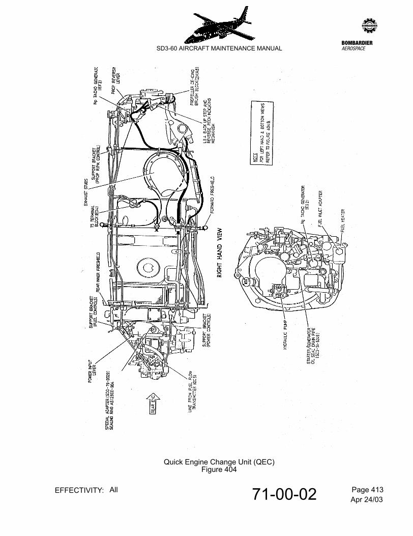
(7) Refer to Figure 404. Disconnect engine controls as follows:-
(a) Power controls
Disconnect Bowdenflex input system from the power input lever and from power control support bracket.
Apr 24/0371-00-02 Page 405EFFECTIVITY: All
zSD3-60 AIRCRAFT MAINTENANCE MANUAL
(b) Fuel condition controls:
Disconnet Eanco cable from the idle reset/cut-off lever at the top of the fuel control unit and from the fuel control support bracket.
Apr 24/0371-00-02 Page 406EFFECTIVITY: All
zSD3-60 AIRCRAFT MAINTENANCE MANUAL
(c) Prop RPM controls:
Detach Eanco cable at quick disconnect on the aft face of the rear fireshield.
NOTE: Operation (8) which follows applys to left installed engine only.
(8) Remove propeller synchronizer actuator as detailed in 61-24-00.
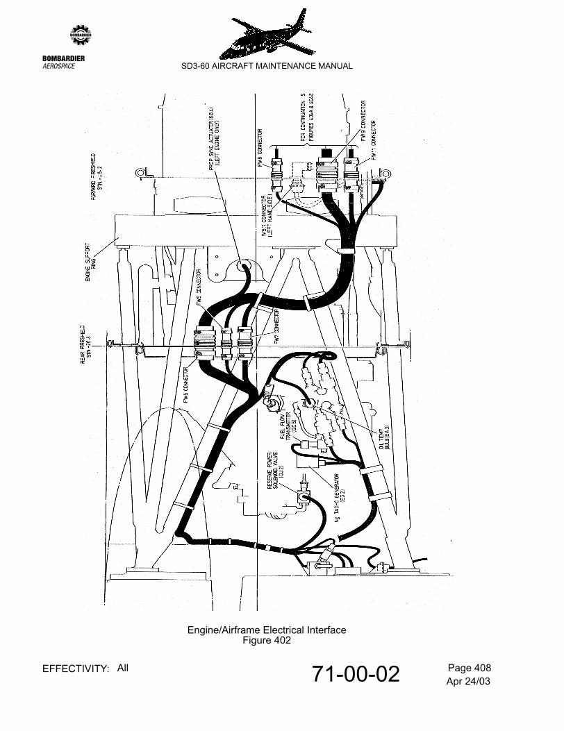
(9) Refer to Figure 402. Make the following electrical disconnection:-
(a) Sockets at FW5, FW6 and FW7 on the forward face of the rear outer fireshield. Note positions and free clipping attaching harness to engine support ring.
(b) Connection to reserve power solenoid valve, idented QJ2.
(c) Connection to fuel flow transmitter, idented QC5.
(d) Connection to Ng tacho-generator, idented EG2.
(e) Connection to oil temperature bulb, idented EA3.
NOTE: The propeller sync actuator connection KG4 (left engine only) will have been freed by previous step (8).
(10) Disconnect fire detection terminal from forward face of wing front spar fireshield. Also free fire sensor clip from engine mounting frame immediately forward of the terminal.
D. Remove engine from airframe
IMPORTANT: BEFORE REMOVAL OF ENGINE, INSPECT ALL FOUR FLEXIBLE MOUNTS, PAYING PARTICULAR ATTENTION TO DRIFT INDICATION AS APPROPRIATE TO MOUNT TYPE. Refer to 71-21-01, pb201. Refer to 71-21-06, pb201.
CAUTION: CHECK THAT MOUNTS NOW FORM THE ONLY CONNECTION BETWEEN THE ENGINE AND THE AIRFRAME.
(1) Position hoisting gear.
(2) Attach engine lifting sling to hook of hoisting gear.
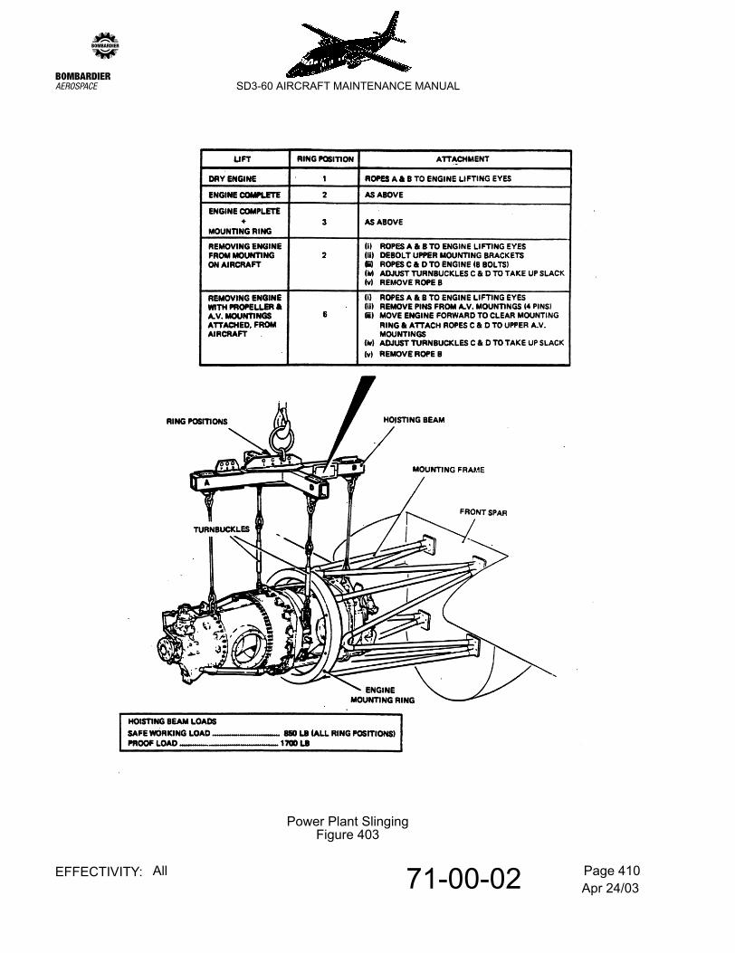
(3) Refer to Figure 403. Sling and remove engine as follows:-
(a) Connect engine sling ropes A & B to engine lifting eyes and take up the slack.
(b) Remove the attachment bolt which secures each of the upper and lower, left and right mount assemblies to the engine mounting ring.
(c) Move power plant forward to allow attachment of sling ropes C & D.
Apr 24/0371-00-02 Page 407EFFECTIVITY: All
zSD3-60 AIRCRAFT MAINTENANCE MANUAL
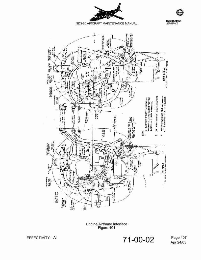
Engine/Airframe InterfaceFigure 401
Apr 24/0371-00-02 Page 408EFFECTIVITY: All
zSD3-60 AIRCRAFT MAINTENANCE MANUAL
Engine/Airframe Electrical InterfaceFigure 402
Apr 24/0371-00-02 Page 409EFFECTIVITY: All
zSD3-60 AIRCRAFT MAINTENANCE MANUAL
(d) Connect sling ropes C & D to upper left and right engine mounts using attachments previously removed (operation (b)).
(e) Disconnect sling rope B.
(f) Carefully withdraw engine from mounting ring; reconnect rope B and lower clear.
NOTE: If a QEC unit is not available for immediate installation, strip removed engine of accessories (para. E) and employ to build replacement engine to QEC standard (para. 3).
CAUTION: IF ENGINE HAS BEEN REMOVED BECAUSE OF OIL SYSTEM METAL CONTAMINATION, THE OIL COOLER MUST ALSO BE REPLACED. ADDITIONALLY, ALL OIL PIPES INTENDED FOR RE-INSTALLATION MUST BE FLUSHED WITH KEROSENE (BRITISH SPEC. DEF2403A OR AMERICAN SPEC VV-K-211D) ANF THOROUGHLY DRIED WITH COMPRESSED AIR BEFORE RE-ASSEMBLY.
E. Remove power plant accessories.
Refer to Figure 404. Refer to Figure 405.
(1) Remove bottom left and right engine mounts as appropriate to type and install engine in maintenance stand.
- Refer to 71-21-01, pb201.- Refer to 71-21-06, pb201.
(2) Remove top left and right engine mounts.
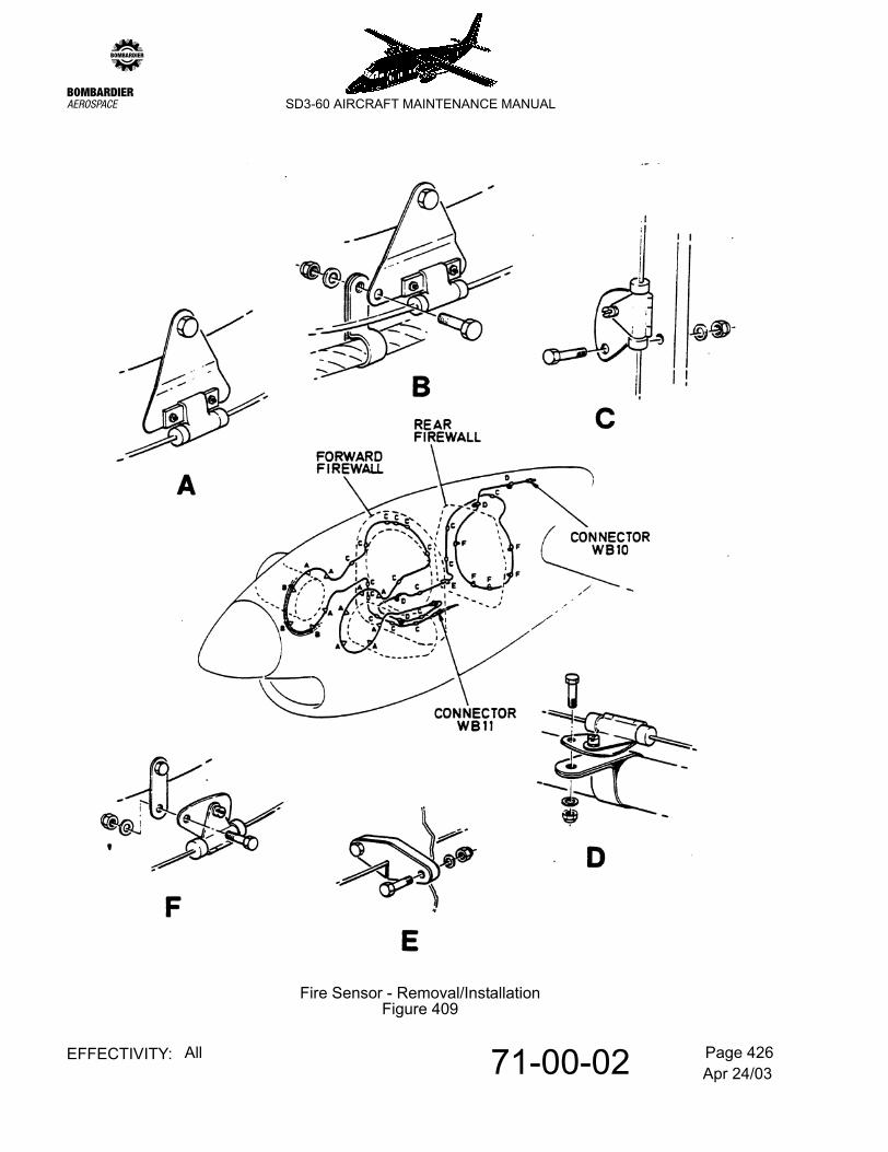
(3) Remove fire sensor and associated clips and attachments. Refer to Figure 409.
(4) Remove exhaust stubs.
NOTE: The equipment referred to in the following operations (5) to (14) inclusive is located where shown. Refer to Figure 404.
(5) Remove power control support bracket.
(6) Remove fuel control support bracket.
(7) Remove prop RPM control support bracket.
(8) Remove power input lever.
(9) Remove hydraulic pump.
NOTE: Leave unions and seals in pump.
Apr 24/0371-00-02 Page 410EFFECTIVITY: All
zSD3-60 AIRCRAFT MAINTENANCE MANUAL
Power Plant SlingingFigure 403
Apr 24/0371-00-02 Page 411EFFECTIVITY: All
zSD3-60 AIRCRAFT MAINTENANCE MANUAL
(10) Remove Ng tacho generator.
(11) From oil pressure port on accessory gearcase, remove special adapter Pt. No. SD3-79-0029 with sealing ring.
(12) Remove fuel flow transmitr.
NOTE: Fit Pratt & Whitney coupling tube, Pt. No. 9381-06 in lieu.
(13) Remove fuel heater inlet adapter and sealing ring.
(14) Remove starter generator seal drain pipe SD3-51-6249 as an assembly (i.e. including elbow).
(15) Refer to Figure 405. Remove starter generator as follows:-
CAUTION: ENSURE THAT THE WEIGHT OF THE UNIT IS NOT TAKEN BY THE SHAFT.
(a) Support the unit and remove the mounting clamp.
(b) Carefully withdraw unit rearwards to disengage shaft plines and remove.
(c) Remove mounting flange and cooling exhaust box from accessory gearbox (secured by four self-locking nuts).
(16) Make the following electrical disconnections:-
(a) Refer to Figure 404.
1 Connections to proximity switches on LBA back up stop and reverse pitch indicating mechanism.
2 ITT wiring, detach from T5 terminal block, idented ED4.
3 Connection to Np tacho generator, idented EF2.
(b) Refer to Figure 405.
1 Connection to lock pitch solenoid, idented KD10.
2 Connection to autofeather valve, idented KC7.
3 Connection to overspeed governor reset valve, idented KB4.
4 Connection to prop sync magnetic pick-up, idented KG5.
5 Connection to propeller de-icing brush block, idented HA8.
(c) Remove harness clipping (note positions for subsequent re-assembly).
Apr 24/0371-00-02 Page 412EFFECTIVITY: All
zSD3-60 AIRCRAFT MAINTENANCE MANUAL
(17) Remove Np tacho generator.
(18) Refer to Figure 405. Remove the torque pressure reference piping as follows:-
(a) Locate pipes SD3-59-6004 and SD3-59-6005.
(b) Detach pipe clipping where attached to oil transfer tubes (note positions and arrangement for subsequent re-assembly).
(c) Remove both pipes.
(d) Remove special adapters and sealing rings from torquemeter oil pressure and static pressure ports. Discard sealing rings.
(19) Remove upper portion of forward fireshield as follows:-
(b) Detach upper to lower fireshield jointing angles.
(c) Remove attachment bolts from engine bulkhead.
(d) Retain attachments with fireshield.
(20) Remove lower portion of forward fireshield as follows:-
(a) Remove drain pipe sealing plates and seals from bottom aft face.
(b) Remove attachment bolts from engine bulkhead and remove lower forward fireshield complete with electrical harness.
(c) Retain attachments with fireshield.
(21) Remove the two upper portions of the rear inner fireshield (retain attachments with the fireshield).
NOTE: The two lower portions of the fireshield were removed to facilitate engine detachment from airframe.
(22) Note position of clipping for subsequent re-installation on replacement powerplant. Refer to Figure 405. Free the assembled drain pipes (four rigid and three flexible) where attached to:-
(25) Remove LBA backup stop and reverse pitch indicating mechanism. Refer to Figure 404.
(26) Remove carbon slipper block from propeller reversing lever. Refer to Figure 404.
3. Quick-engine change QEC build procedure
Refer to Figure 404. Refer to Figure 405.
A. General Notes
(1) A QEC unit is equipped from spares holdings or a combination of spares and functional accessories taken from an unserviceable engine (para 2.C.).
(2) The procedure is provided to:-
(a) enable operators to build standby QEC units.
(b) prepare an engine required for immediate installation to a convenient pre-installation state.
(3) Torque tighten all bolts attaching support brackets, fireshields etc. to engine flanges to 36 - 40 lb in. Where self-locking nuts are employed, note the torque necessary to turn the nut on the bolt before seating the nut and add this value to that quoted, using the newly established value as the installation figure.
B. Procedure
(1) Mount engine in QEC build stand T360.71.05.
(2) Fit carbon slipper block Pt. No. A3044 to the propeller reversing lever which overhangs the propeller mounting flange. Refer to Figure 404.
(3) Refer to Figure 404. Fit LBA back-up stop and reverse pitch indicating mechanism to the thrust cover on the reduction gearbox. Torque tighten attachment nuts to 145-165 in.lbs.
NOTE: If engine is intended for immediate installation, rigging is performed post-installation on airframe.
(4) Fit propeller de-icing brush block assembly. Refer to Figure 405.
(5) Refer to Figure 405. Fit overspeed governorusing replacement gasket Woodward Pt. No. 206685 or Pratt & Whitney Pt. No. 3010818. Torque tighten attachment nuts 170-190 lb. in.
NOTE: Coat gasket with Dow Corning 7 Compound release agent or equivalent.
(6) Fit Np tacho-generator together with gasket MS91341-01. Refer to Figure 404.
Apr 24/0371-00-02 Page 416EFFECTIVITY: All
zSD3-60 AIRCRAFT MAINTENANCE MANUAL
(7) Refer to Figure 405. Fit forward portion of engine drains system as follows:-
(a) Fit elbow Pt. No. AN833-4K, sealing ring Pt. No. AS12800-904 and locknut AN924-4K to propeller shaft oil seal drain port.
NOTE: Observe installed engine for angular setting of elbow.
(b) Connect pipe, Pt. No. SD3-51-6247 to elbow and clip to adjacent pressure oil tranfer tube using clips Pt. No. HT0813/4C (2 off) and HT0813/10C (2 off).
NOTE: Leave flexible pipe, Pt. No. SD3.51.0081 hanging free.
(c) Connect combustion drain valve piping assembly, comprising two rigid pipes, a tee-piece and a flexible pipe as follows:-
1 Connect pipe Pt. No. SD3-51-6246 to forward valve.
2 Connect pipe Pt. No. SD3-51-6244 to rear valve.
NOTE: Leave flexible pipe, Pt. No. SD3-51-0077 hanging free.
(d) Connect fuel manifold purge system piping (comprising one rigid pipe and one flexible pipe) to the flow divider dump valve as follows:-
1 Connect pipe, Pt. No. SD3-51-0068 to valve and clip to adjacent fuel inlet line using clips HT0813/4C (2 off).
NOTE: Leave flexible pipe, Pt. No. SD3-51-0082 hanging free.
(8) Fit the two upper portions of the rear inner fireshield.
NOTE: Two lower portions of fireshield are fitted post-engine installation.
(9) Fit lower portion of forward fireshield (complete with electrical harness) as follows:-
(a) Ease free portion of peripheral seal over front of engine and manoeuvre fireshield into position on aft face of engine centre fireseal bulkhead.
(b) Bolt fireshield to bulkhead.
(c) Fit the two drain pipe sealing plates, Pt. No. SD3-51-0095 and SD3-51-0097 together with respective associated seals SD3-51-0096 and SD3-51-0098 to the bottom rear face of the fireshield.
(10) Fit upper portion of forward fireshield as follows:-
(a) Place in position on aft face of engine centre fireseal bulkhead.
(b) Bolt to bulkhead.
Apr 24/0371-00-02 Page 417EFFECTIVITY: All
zSD3-60 AIRCRAFT MAINTENANCE MANUAL
(c) Fit peripheral seal upper retaining angle, Pt. No. SD3-50-0122.
(11) Bolt upper to lower forward fireshield jointing angles together.
(12) Arrange forward portion of electrical harness and connect to the following equipment:-
NOTE: Where necessary, employ Dymotape to identify appropriate equipment with the idents quoted.
(a) Refer to Figure 404.
1 Proximity switches on LBA back-up stop and reverse pitch mechanism.
2 ITT wiring, attach to T5 terminal block, idented ED4.
3 Np tacho-generator, idented EF2.
(b) Refer to Figure 405.
1 Lock pitch solenoid, idented KD10.
2 Autofeather valve, idented KC7.
3 Overspeed governor reset valve, idented KB4.
4 Prop synch magnetic pick-up, idented KG5.
5 Prop de-icing brush block, idented HA8.
(c) Fit harness clipping.
(13) Refer to Figure 405. Install torque pressure reference piping as follows:-
(a) Fit adapter, Pt. No. SD3-79-0034 and sealing ring AS12800-903 to torquemeter static pressure port; secure with two attachment bolts and washers.
(b) Fit adapter, Pt. No, SD3-79-0029 and sealing ring AS12800-912 to torquemeter oil pressure port. Torque tighten to 400 ± 25 lb. in.
(c) Fit pipes SD3-59-6004 and SD3-59-6005 to respective torquemeter oil pressure and static pressure adapters, orientating as shown.
(d) At the positions noted during accessory removal process, fit pipe clipping to appropriate oil transfer tubes.
(14) Refer to Figure 405. Fit starter generator as follows:-
(a) Remove blanking plate from mount pad on accessory gearcase.
Apr 24/0371-00-02 Page 418EFFECTIVITY: All
zSD3-60 AIRCRAFT MAINTENANCE MANUAL
(b) Position cooling exhaust box, Pt. No. SD3-79-0083 on the four studs projecting from the mount pad (exhaust box outlet to top).
(c) Install unit mounting flange on studs and secure with four self-locking nuts, Pt. No. AS8600-G. Torque tighten nuts to 150 lb. in.
(d) Refer to 12-10-79, pb1. Lubricate the splined shaft with clean engine oil to spec. referred. Install new O-ring Pt. No. MS 29561-113.
CAUTION: MAINTAIN SUPPORT OF UNIT DURING (E) WHICH FOLLOWS I.E. DO NOT PERMIT WEIGHT OF UNIT TO BE TAKEN BY SHAFT.
(e) Align the starter generator splined shaft with the drive on the engine and slide into place with the cooling inlet duct at rear orientated horizontally to left.
(f) Fit attachment clamp; torque tighten clamp bolt to 70 lb. in.
(15) Refer to Figure 404. Fit starter generator seal drain pipe assembly, Pt. No. SD3-51-6249.
NOTE: Orientate elbow to right as shown.
(16) Fit fuel heater inlet adapter Pt. No. AN815-4C and sealing ring Pt. No. AS12800-910 to fuel heater inlet port. Refer to Figure 404.
(17) Refer to Figure 404. Fit flow transmitter in lieu of coupling tube Pt. No. MS9381-06 (supplied with engine).
(18) Refer to Figure 404. Locate oil pressure port and fit the following:-
(a) Sealing ring AS12800-912
(b) Special adapter, Pt. No. SD3-79-0029.
NOTE: Torque tighten adapter to 400 ± 25 lb. in.
(19) Refer to Figure 404. Fit Ng tacho generator together with gasket MS9134-01.
(20) Refer to Figure 404. Fit hydraulic pump as follows:-
NOTE: Pump ports should be equipped with relevant unions and seals in readiness for subsequent connection to airframe piping.
(a) Replace bolts supplied with engine with studs, Pt. No. SD3-73-0851 (4-off). Insert long-threaded end in engine and torque tighten to 54 lb. in.
(b) Fit interface gasket supplied with engine or fit new gasket Pt. No. MS9134-01.
(c) Align pump shaft and slide pump into position, case drain connection uppermost.
Apr 24/0371-00-02 Page 419EFFECTIVITY: All
zSD3-60 AIRCRAFT MAINTENANCE MANUAL
(d) Lubricate stud threads with engine oil and secure pump in position with four attachment nuts and washers. Torque tighten to 54 lb. in. and wirelock.
(21) Refer to Figure 404. Fit propeller RPM control support bracket
(22) Refer to Figure 404. Fit fuel control support bracket
(23) Refer to Figure 404. Fit power control support bracket
(24) Refer to Figure 404. Fit power input lever
NOTE: If engine is required for immediate installation, lever is finally rigged post-installation on airframe.
(25) Fit exhaust stubs. Refer to 78-10-01, pb201.
(26) Install fire sensor and associated clips and attachments. Refer to Figure 409.
NOTE: Operations (27) thru (30) which follow detail the rigging of a QEC which is being prepared as a standby unit.
(27) Refer to Figure 406. Rig the LBA back-up stop and reverse pitch indicating mechanism as follows:-
NOTE: The procedure will be adequate to permit flight, however the engine installed procedure should be performed at the next available opportunity. Refer to 61-21-00, pb201.
(a) Fit pitch indication setting tool T360.71.06 on propeller mounting flange as shown on detail C. Secure with four propeller mounting bolts, Pt. No. b-3339.
NOTE: 1. Propeller shaft should initially be rotated to a position which will permit 'cut outs' in rear wall of setting tool dummy low stop collar to accept slipper blocks of pitch indicating mechanism and propeller reversing lever.
2. Ensure setting tool is fully mated with flange.
(b) Slacken attachments of both proximity switches.
(c) Adjust setting tool such that the FP. BACK-UP face of bar gauge can contact respective rear faces of dummy low stop collar and propeller flange.
(d) Adjust fine pitch proximity switch on its mounting plate slots such that just over 50% of the switch is now covered by target plate on camplate assembly. Tighten attachments.
(e) Adjust setting tool to position determined by the REVERSE face of bar gauge and set reverse proximity switch on its slots such that just over 50% is covered by target plate on camplate assembly. Tighten attachments.
NOTE: Leave setting tool installed to permit subsequent rigging of engine leakages.
(28) Rig the front linkage
Refer to Figure 407.
(a) Refer to Figure 406. Adjust setting tool T360.71.06 such that the FEATHER face of the bar gauge can just be inserted where shown. Maintain this setting.
(b) Disconnect fuel governor reset arm (11) from fuel governor interconnecting rod (2).
(c) Rig the cased wire-rope assembly (propeller reversing system) as follows:-
1 Back-off forward sliding link (9) to detach from the clevis attachment terminal. Unscrew and retain the wire-rope ball end (split collet) thus exposed.
2 Refer to Figure 408. Disconnect rear clevis (1) from propeller control cam. Lift clevis clear of cam and position alongside (nearest engine centreline). Withdraw rearwards sufficiently to permit sliding link (21) to be unscrewed from clevis attachment terminal. Wind exposed ball-end on wire rope forward and re-introduce wire-rope to 'bottom out' in clevis terminal; maintain this condition and wind back ball-end to seat in terminal and reconnect sliding link.
3 Push rear clevis forward to feed wire-rope through casing. Refit ball end retained at 1, winding back sufficiently to ensure rope 'bottoms out' when re-introduced to forward clevis attachment terminal; maintain this condition, wind ball end forward to seat in terminal and reconnect forward sliding link.
4 Ensure that propeller reversing lever (3) is connected in the beta control valve clevis (4) and the carbon slipper block (5) is located in the dummy low stop collar.
5 Refer to Figure 408. Operate power input lever (33) to place follower lever (15) in a mid travel position between FLIGHT IDLE and max power.
6 Refer to Figure 408. Reconnect rear clevis (1) to the third hole from the top in the propeller control cam (23). Check clevis is in safety (through inspection hole).
7 Disconnect forward clevis (24) from the propeller reversing lever (3).
NOTE: A sliding spacer is installed in the attachment hole. Do not lose when disconnecting.
8 Pull forward firmly on front sliding link (9) to eliminate cable backlash and adjust clevis end (24) such that when re-aligned with pick-up hole (spacer re-fitted) in
Apr 24/0371-00-02 Page 422EFFECTIVITY: All
zSD3-60 AIRCRAFT MAINTENANCE MANUAL
reversing lever (3), the slot end face of the beta control clevis (4) is flush with the beta valve stop nut (10).
NOTE: Ensure clevis end (24) is in safety (through inspection hole).
(d) Adjust length of fuel governor interconnecting rod (2) to exactly align hole through it with the outer hole through fuel governor reset arm (11). Shorten the interconnecting rod by 1/2 turn and reconnect.
(e) Tighten nuts and approriately lock (cotter pins/lockwire).
(29) Rig the rear linkage
Refer to Figure 408.
NOTE: The FCU is substantially pre-rigged by the engine manufacturer to minimize pre-engine run rigging activity; however the following aspects of the rigging should be checked.
a Check that FCU interconnect rod (12) is set to nominal length of 8.25 in. between centres and is connected between the outer hole in arm (18) and the third hole from the top in FCU activating lever (20).
b Check for free movement of input lever (33) between flight idle and max power (FCU max forward stop contacted). Return to flight idle and insert rigging pin in cambox assembly to maintain flight idle.
c Check that input lever (33) is installed on cambox shaft (16) at 5 to 10° below horizontal; if necessary, remove and re-install to comply.
(30) Remove setting tool T360.71.06 as follows:-
(a) Remove the four mounting bolts.
(b) Rotate setting tool and propeller shaft such that cut-outs on the rear wall of the setting tools dummy low stop collar permit tool to be extricated from slipper blocks.
NOTE: Rigging and associated checks of the fuel condition and propeller RPM controls are performed post engine installation.
(31) Assemble top left and right hand engine mounts and associated gaskets on engine.
NOTE: Refer to 71-21-01, pb201. Refer to 71-21-06, pb201. As appropriate to mount type. Ignore references to aircraft attachment contained therein.
(32) Place botton left and right hand mounts in a stowage bag and secure to engine until required immediately prior to installation on airframe.
Apr 24/0371-00-02 Page 423EFFECTIVITY: All
zSD3-60 AIRCRAFT MAINTENANCE MANUAL
Front Linkage - Rigging (QEC Build)Figure 407
Apr 24/0371-00-02 Page 424EFFECTIVITY: All
zSD3-60 AIRCRAFT MAINTENANCE MANUAL
Rear Linkage - Rigging (QEC Build)Figure 408
Apr 24/0371-00-02 Page 425EFFECTIVITY: All
zSD3-60 AIRCRAFT MAINTENANCE MANUAL
4. Installation
A. General Notes
WARNING: THE FOUR BOLTS WHICH SECURE THE ENGINE MOUNTS TO THE MOUNTING RING MUST BE SUBJECTED TO NONDESTRUCT TESTING BEFORE INSTALLATION, I.E. A MAGNETIC PARTICLE INSPECTION PER ASTM STANDARD E1444 (REPLACE PART IF CRACKS ARE FOUND). THIS IS ADDITIONAL TO THE BOLTS INSPECTION REQUIREMENTS DETAILED, AS APPROPRIATE TO MOUNT TYPE. REFER TO 71-21-01, PB201. REFER TO 71-21-06, PB201.
B. Preparation for installation
(1) Refer ro Figure 403. Connect sling ropes A, B, C & D to power plant and remove unit from build stand.
(2) Ignoring references to airframe attachment, fit bottom left and right hand engine mounts and associated gaskets to engine (as appropriate to mount type). Refer to 71-21-01, pb201. Refer to 71-21-06, pb201.
C. Install engine on airframe
(1) Check that airframe mounted controls and equipment are clear of engine mounting ring.
(2) Raise engine to a position immediately forward of installation position.
(3) Disconnect sling rope B and carefully maneouvre engine rearwards until aft slinging point is passed through mounting ring. Reconnect sling rope B.
(4) Free sling ropes C and D and further manoeuvre engine rearwards to align engine mounts with pickup brackets on inner face of engine support ring.
(5) At each of the four locations, fit mount-to-airframe interfacing attachments as follows:-
(a) With washer under head, insert support ring bracket to mount attachment bolt from rear; assemble washer and nut on bolt and torque tighten to 450-500 lb. in.
(b) Lock attachment nut with split pin.
(6) Remove engine sling.
D. Post installation procedures
(1) Initial actions:
(a) Install propeller. Refer to 61-10-01, pb201.
If replacement engine is a standby QEC unit, the operations denoted thus * should be ignored.
Apr 24/0371-00-02 Page 426EFFECTIVITY: All
zSD3-60 AIRCRAFT MAINTENANCE MANUAL
Fire Sensor - Removal/InstallationFigure 409
Apr 24/0371-00-02 Page 427EFFECTIVITY: All
zSD3-60 AIRCRAFT MAINTENANCE MANUAL
(b) Fit two lower portions of rear inner fireshield.
(2) Left side of engine actions:
Refer to Figure 401.
NOTE: In the interests of clarity, it may occassionally be advantageous to refer to view relative to opposite engine (i.e. where plumbing routeing obscures referred item/s on view under consideration.
(a) Identify and connect ignition leads to ignition exciter, idented KA7 (unit is located on lower left side of engine tubular support structure).
NOTE: Fit ignition lead ties at positions noted during engine removal procedure.
(b) Identify and connect fire sensor connector WB11 to rear face of forward fireshield.
(c) Reconnect air-conditioning P3 bleed supply flexible hose to P3 adapter (located at 9 o'clock position on engine) as follows:-
1 Connect free end of bonding lead which is attached to the bottom left mount pickup bracket on the engine support ring to the bottom aft attachment bolt securing the P3 adapter.
NOTE: Torque tighten bolt to 75-85 lb. in., then wirelock.
2 Orientate flex hose through engine support ring and connect to P3 adapter using clamp Aeroquip Marman, Pt. No. 4573-100 and gasket SD3-74-0060/B.
NOTE: Initially torque clamp to 21 lb. in., then tap around periphery to ensure correct bedding. Finally tighten to 30 lb. in.
3 Fit P-clip which secures flex hose to cleat on inner face of engine support ring.
NOTE: Initially torque tighten to 25 lb. in. , then tap around periphery to ensure bedding; finally tighten to 30 lb. in.
5 Refit aft clamp lagging.
(d) Refit P2.5 bleed adapter and reconnect associated flex hoses as follows:-
1 Locate P2.5 bleed port (12 o'clock position immediately aft of engine mounting ring) and remove blanking plate. Retain four attachment bolts.
2 Fit P2.5 bleed adapter and gasket (respective Pt. Nos. SD3-74-6172 and SD3-74-6188) to bleed port employing bolts retained at 1. Wirelock attachments.
Apr 24/0371-00-02 Page 428EFFECTIVITY: All
zSD3-60 AIRCRAFT MAINTENANCE MANUAL
3 Re-attach flexible hoses to adapter employing clips retained during engine removal procedure.
NOTE: The right hand hose serves the aerofoil de-icing system and the left, the air conditioning system.
(e) Identify and reconnect the oil cooler flexible pipes (supply and return). Torque tighten connections to 300-500 lb. in. and wirelock.
(f) Connect the four flexible hydraulic pipes, idented MP, PI/INLET, CD/PCD and DRAIN to the hydraulic pump.
NOTE: Torque tighten drain connection to 40-65 lb. in. (remaining connections are not torque tightened until subsequent bleed operations are performed).
(g) Reconnect compressor wash flexible pipe to adapter on aft face of rear inner fireshield. Wirelock.
(h) Perform the following at the starter/generator:-
1 Remove the terminal block cover.
2 Remove the temporary insulation from the unit cables and connect to the terminal block according to the cable marker sleeves. Torque tighten. Refer to 20-09-07, pb1.
3 Refit cable clamp and terminal block cover.
4 Connect the bonding lead at the upper attachment point of the inlet duct with the attachments retained on removal. Torque tighten the nut from 7 to 9 lbf. in.
5 Reconnect cooling inlet and outlet flexible bellows employing clipping retained during engine removal procedure.
(3) Right side of engine actions:
Refer to Figure 401.
NOTE: 1. Unless otherwise stated, Refer to Figure 401 (viewing left or right engine as appropriate).
2. In the interest of clarity, it may occassionally be advantageous to refer to view relative to opposite engine (i.e. where plumbing routeing obscures referred item/s on view under consideration.
Apr 24/0371-00-02 Page 429EFFECTIVITY: All
zSD3-60 AIRCRAFT MAINTENANCE MANUAL
(a) Refer to Figure 402. Identify and reconnect forward portion of engine harness to appropriate connectors FW5, FW6 and FW7 on forward face of rear fireshield. Fit clipping which secures harness to engine mounting ring.
NOTE: Step (b) which follows applies to left installed engine only.
(b) Fit propeller synchronizer actuator. Refer to 61-24-00, pb201.
(c) Refer to Figure 402. Identify and attach free connectors of aft portion of engine harness to:-
- Reserve power solenoid valve, idented QJ2.- Fuel flow transmitter, idented QC5.- Ng tacho-generator, idented EG2.- Oil temperature bulb, idented EA3.
(d) Connect fire detection terminal to connector on wing front spar fireshield. Also attach fire sensor clip immediately forward of the terminal to the engine mounting frame.
(e) Install torque indication pipes, SD3-79-6006 (reduction gearcase air pressure datum) and SD3-79-6007 (torquemeter oil pressure reference line) between appropriate connections respectively located immediately aft and forward of the rear outer and forward fireshields. Fit bulkhead seals and cover plates.
NOTE: When fitting the two-ply seals at each of the referred fireshields, position such that pipe accommodating splits are not coincident.
(f) Identify and connect the oil pressure indication flexible pipe to oil pressure adapter on engine. Torque tighten to 40-65 lb. in and wirelock.
(g) Refer to Figure 405. connect the three flexible pipes shown thereon to the appropriate adapters on the rear outer fireshield.
The pipe systems and related torque tightening values are:-
(h) Identify and connect the following fuel flexible pipes.
1 Fuel inlet-attach to inlet connection on fuel heater. Torque tighten to 200-350 1b.in. and wirelock.
2 Fuel purge line-attach to upper connection of tee-piece on top of fuel pump. Torque tighten to 40-65 lb. in. and wirelock.
3 Fuel pump drain - attach to adapter beneath pump. Torque tighten to 40-65 lb. in.
Apr 24/0371-00-02 Page 430EFFECTIVITY: All
zSD3-60 AIRCRAFT MAINTENANCE MANUAL
(i) Reconnect starter/generator seal drain flexible pipe to elbow in piping from unit mounting pad.
(j) Reconnect flexible oil breather pipe to connection on accessory gearcase. Secure with hose clamp AGS 3925-0.
(k) Connect and rig the fuel condition and propeller RPM control circuits (refer to power plant adjustment/test section).
(l) * Connect and rig the power control circuit (refer to power plant adjustment/test section).
NOTE: If engine was a standby QEC unit, engine mounted linkages will already be rigged and it should only be necessary to place flight compartment and related engine levers in compatible rigged positions to permit connection. Refer to 76-10-00, pb501.
(m) * Rig the LBA back-up stop and reverse pitch indicating mechanism. Refer to 61-21-00, pb201.
(4) Completion actions:
(a) Perform those aspects of priming and bleeding the hydraulic power circuit which relate to the hydraulic pump. Refer to 29-11-00, pb301.
NOTE: After priming and bleeding, tighten connections on pump to the following values:-
(b) Attach main intake cowl restraint cable and reconnect electrics on rear bulkhead at:
- Plug break EPB1- Engine terminal block ETB4
(c) Refit cowl panels, leaving main intake cowl open at this stage.
NOTE: When fitting panel 410AT it will be necessary to open the oil filler access door contained within the panel. This will provide access to attach the starter generator cooling outlet vent to the panel.
(d) Perform engine depreservation procedure. Refer to 71-00-00, pb301.
(e) Perform ground check run including performance (power) checks. Refer to 71-00-02, pb501.
Main Pressure MP - (270 -300 1b.in. and wirelock).Pump Inlet PI - (150 - 250 1b.in and wirelock).Case Drain PCD - ( 40 - 65 1b.in and wirelock).
IN ADDITION TO RUNNING LIMITATIONS AND ENGINE RUN-UP PROCEDURES, THIS SECTION CONTAINS THOSE ENGINE RIGGING INSTRUCTIONS AND RIGGING CHECKS AND ADJUSTMENTS WHICH ARE EITHER (a) NOT COVERED BY THE ENGINE MAINTENANCE MANUAL OR (b) THE INFORMATION CONTAINED IN THE ENGINE MANUAL DOES NOT CATER FOR ENGINE SETTINGS SPECIFIC TO THE SD3-60 AIRCRAFT.
THOSE UNDER CATEGORY (b) ARE IDENTIFIED THUS * AND TAKE PRECEDENCE OVER CONFLICTING INFORMATION IN THE ENGINE MANUAL.
NOTE: The rigging of the autofeather microswitches must be verified following an engine, major engine component, or power control cable change - that is, any maintenance that requires retensioning of the power control cables. Refer to 61-22-01, pb201.
1. Power Plant Limitations
A. Fuel
Refer to 12-10-28, pb1.
B. Oil
(1) Types. Refer to 12-10-79, pb1.
(2) Temperature. As appropriate to operating conditions. Refer to Table 501.
(3) Pressure. As appropriate to operating conditions. Refer to Table 501.
C. Operating parameters
Refer to Table 501.
D. Propeller feathering
POWER lever must not be below FLIGHT IDLE when feathering the propeller (over-temperaturing of the engine will occur if PROP lever is selected to FEATHER whilst POWER lever is in the Beta range.
Jan 30/0971-00-02 Page 502EFFECTIVITY: All
zSD3-60 AIRCRAFT MAINTENANCE MANUAL
E. Electrics (Starting)
A starting cycle shall not be attempted unless the indicated voltage on the aircraft voltmeters is within the following limits:-
NOTE: For an external power start, internal battery voltages may be as low as but not less than 14V.
The starting cycle must be abandoned if it is evident that engine ignition has not been achieved by 25 seconds from the selection of an engine START - STOP switch to START.
The number of starts in any 20 minute period must not exceed three. A ventilation cycle (dry motoring run) is to be considered as a start; i.e. in the event of an unsuccessful start, followed by a ventilation cycle and another unsuccessful start, a 20 minute period must elapse before a further ventilation cycle and starting attempt is carried out.
After starting one engine, a generator-assisted start of the second engine must not be attempted until the load on the generator driven by the running engine is less than 250 amperes.
Internal Battery External Battery External Power
Minimum voltage 22 22 22Maximum voltage - - 28
Jan 30/0971-00-02 Page 503EFFECTIVITY: All
zSD3-60 AIRCRAFT MAINTENANCE MANUAL
F. Instrument limit markings
The following is an explanation of the markings on the power plant instruments:-
Instrument Marking Explanation
Propeller speed indicator Red radial line Maximum value 1700 rpmGreen arc 1200 to 1700 rpm
Normal operating range
Gas generator speed indicator
Red radial line Maximum value 104.0%
Green arc Normal operating range 56% to 104.0%Torquemeter Red radial line Maximum value 4400 lb. ft
Yellow arc Precautionary range 3625 to 4400 lb.ft.Green arc Normal operating range 0 to 3625 lb.ft.
Inter turbine temperature gauge
Red radial line Maximum value 855°C
Yellow arc Precautionary range 840 to 855°CGreen arc Normal operating range 400 to 840°C
Oil temperature gauge Red radial line Maximum value 110°CYellow arc Precautionary range 105 to 110°CGreen arc Normal operating range 20 to 105°C
Oil pressure gauge Red radial line Minimum value 60 psi Maximum value 135 psi
Yellow arc Precautionary range 60 to 90 psiGreen arc Normal operating range 90 to 135 psi
Jan 30/0971-00-02 Page 504EFFECTIVITY: All
zSD3-60 AIRCRAFT MAINTENANCE MANUAL
Power Plant Operating LimitationsTable 501
NOTES:
(1) 100% Ng corresponds to 37468 rpm.
(2) All bleeds OFF
(3) 0 to 400 prpm is only permissible with propeller feathered.
(4) Times in brackets refer to maximum times for which associated conditions may prevail.
CAUTION: DO NOT RUN AN ENGINE WITHOUT THE PROPELLER SPINNER DOME INSTALLED. WITHOUT THE OPPOSING SUPPORT OF THE SPINNER DOME, THE CENTRIFUGAL FORCE PRODUCED BY THE SPINNING PROPELLER COULD DAMAGE THE DE-ICER WIRE HARNESS.
NOTE: The conditions under which check run is performed and the results obtained should be recorded on a Ground Run Check Sheet. Refer to Figure 509.
A. Action prior to ground running
(1) Position aircraft facing into wind.
(2) Chock wheels
(3) Position serviceable fire fighting equipment adjacent to the aircraft.
(4) Ensure area around aircraft is free of loose objects.
(5) Check engine oil level. Refer to 12-10-79, pb301.
(6) Check engine intakes and exhausts are free from foreign objects.
(7) Ensure danger areas around aircraft are clear of personnel.
(8) Refer to emergency procedures (para. 10.).
B. Pre-start checks:-
(1) EXTERNAL
(2) INTERNAL
Engine Blanks removedEngine cowls SecureEngine vents CheckPropellers Feathered and free to rotateEngine fire bottle discs Green (4)Landing gear locking pins Fitted
Cabin doors ClosedPortable fire extinguishers Stowed1D and 2D circuit breakers InParking brake OnLanding gear lever DOWN
Jan 30/0971-00-02 Page 506EFFECTIVITY: All
zSD3-60 AIRCRAFT MAINTENANCE MANUAL
EMERGENCY BRAKE OnLEFT and RIGHT ENGINE L.P. VALVES OPENCROSSFEED VALVE Operation free, set SHUTLANDING GEAR DOWN EMERGENCY handle
Up (not selected)
Control locks Engaged
4P panel: ELECTRICS (dc. power)LEFT and RIGHT BATTERY switches ONELECTRICAL MASTER switch INTERNALLeft and right voltages 22V min. (internal start)
14V min. (external start)Tail battery voltage Check 14V min.ESSENTIAL SERVICES switch/indicators Normal (vertical)SHEDDING BUS switches EMERGENCYGENerator switches OFF
For starting with external electrical supply:-ELECTRICAL MASTER switch EXTERNALBusbars coupled Check indicatorVoltages Check (22 - 28V) ground supplyGROUND SUPPLY, GROUND SERVICES BUS indicators
Appropriate to supply
4P panel: ELECTRICS (A.C. power)L, R & STANDBY INVerter switches Press 'on' (OFF display goes out)Inverter voltages 110 - 120VInverter frequencies 380 - 420 HzL & R INV switches 'off' in turn, check standby takes over, then
'on'.START MASTER switch NORMALIGNITION LEFT and RIGHT switches OFFFIRE EXTINGUISHER discharge lights outRESERVE POWER switches left and right OFF
10P panel: LIGHTINGAircraft lights As required
Jan 30/0971-00-02 Page 507EFFECTIVITY: All
zSD3-60 AIRCRAFT MAINTENANCE MANUAL
4P panel: ANTI-ICING ServicesANTI-ICE VANE switches ON (ANTI-ICE indicated) then OFF
(NORMAL displayed)Other anti-ice systems As required
4P panel: FUEL ServicesFWD and AFT tank contents As requiredLEVELLING VALVES switch/indicator Press for 'in line' (open) display if AFT tank
contents less than 1800 lb. (820 Kg.)BOOSTER PUMP switches, left and right OFFFILTER warning lights out
7P: HYDRAULIC SERVICESCONTENTS CorrectPUMP INLET VALVE switches L & R OPENNOSEWHEEL STEERING switch ONHYDRAULIC SERVICES pressures Noted
1P and 2P panels:Audio As requiredOutside air temperature NotedEngine instruments ServiceableLanding gear indicators 3 greens
Centre console:POWER levers and ground/air lever lock balk,
Exercised up to control, then set toFLIGHT IDLE
PROP levers Exercised and set to FEATHERFUEL levers OFF
9P panel: AIR CONDITIONING ServicesENGINE bleed switch/indicators, left and right
Off-line (OFF)
Non-bleed systems As required
Jan 30/0971-00-02 Page 508EFFECTIVITY: All
zSD3-60 AIRCRAFT MAINTENANCE MANUAL
C. Starting checks:-
11P panel: DOORS/SYSTEMS - TESTDOORS warning indicators SHUTLIGHT FILAMENT test switch TEST, check all warning lights; red bright,
all others dim. Set BRT or DIM as required.ENGINE FIRE WARNING LEFT & RIGHT TEST and hold in turn, checking:-
(a) Fire bell rings and is cancelled when the relevant (illuminated) FIRE P to C (press-to-cancel) module on panel 1P is operated.(b) The undernoted warning lights (left or right as appropriate) are lit during test:-
- FIRE FAULT module (panel 1P)- FIRE EXTINGUISHER SHOT 1 & 2 buttons (panel 4P).- Red light in ENGINE LP VALVE lever (roof console) - pre mod 7114 aircraft only.- Red light in FUEL lever (centre console)
SMOKE DETECTORS FWD & AFT test switches
No. 1 and No. 2 TEST in turn. Check appropriate SMOKE warning module illuminates.
Throttle full power switches (Reserve Power System)
Flying control locks DisengagedPOWER levers Advance to 90% Ng alignment marks
(orange).RESERVE POWER switches (4P) ARM, check associated indicators (panel
1P) display RTOP ON.POWER levers Slowly retard and check that indicator
captions immediately go out.Return levers to FLIGHT IDLE.
Flying control locks Engage
SHEDDING BUS switches EMGYSTART MASTER switch ARMED
Jan 30/0971-00-02 Page 509EFFECTIVITY: All
zSD3-60 AIRCRAFT MAINTENANCE MANUAL
D. Start first engine
CAUTION: WHENEVER GAS GENERATOR FAILS TO LIGHT UP WITHIN 10 SECONDS AFTER MOVING THE FUEL CONDITION LEVER TO GROUND, SHUT OFF FUEL, STARTER AND IGNITION.
ALLOW A 30 SECOND FUEL DRAINING PERIOD, FOLLOWED BY 15 SECOND VENTILATION CYCLE (DRY MOTORING RUN - PARA. 4.) BEFORE ATTEMPTING ANOTHER START. IT IS NOT NECESSARY TO ALLOW RUNDOWN AFTER DRY MOTORING RUN BEFORE RESUMING START.
IF, FOR ANY REASON, STARTING ATTEMPT IS DISCONTINUED, ALLOW ENGINE TO COME TO COMPLETE STOP AND THEN ACCOMPLISH DRY MOTORING RUN. REPEAT COMPLETE STARTING SEQUENCE (OBSERVING STARTING LIMITS - REFER TO PARA. 1.).
E. Start second engine
BOOSTER PUMP switch ONStart switch STARTIGNITION switch NORMAL, above 10% NgFUEL lever GROUND, when Ng stabilised (min. 12%).'Light Up' Within 10 secondsITT Monitor (855 to 1000°C) for 5 sec.Start and ignition lights Extinguished above 50% NgGas generator RPM Stabilised at 71 ±1%Oil Pressure 90 psi. minimum (warning light out)
HYDRAULIC SERVICES pressures:MAIN SYSTEM 3000 +200 -100 psiNORMAL WHEEL BRAKESLEFT AND RIGHT
Generator ammeter (1st engine) Below 250 amp (internal start only)Start as for 1st engine
Jan 30/0971-00-02 Page 510EFFECTIVITY: All
zSD3-60 AIRCRAFT MAINTENANCE MANUAL
F. After start checks
WARNING: (A) POWER LEVER MOST NOT BE BELOW FLIGHT IDLE WHEN FEATHERING THE PROPELLER (OVER-TEMPERATURING OF THE ENGINE WILL OCCUR IF FEATHER IS SELECTED WHILST POWER LEVER IS IN BETA RANGE).
(B) RESTRICT IDLING TIME IN FEATHER TO AVOID EXCEEDING OIL TEMPERATURE MAX. LIMIT (110°C).
Perform rigging checks as detailed in para. 7.
WARNING: ENSURE ENGINE IS SHUTDOWN BEFORE PERFORMING ANY ADJUSTMENTS ON ENGINE-MOUNTED EQUIPMENT. THIS IS ESSENTIAL DUE TO CLOSE PROXIMITY OF PROPELLER AND EXHAUST NOZZLES.
Perform system checks as detailed in para. 8.
Carry out performance checks (if appropriate) - refer to para. 9.
START MASTER switch NORMALIGNITION switches LEFT and RIGHT OFFGENERATOR switches left and right ONELECTRICAL MASTER switch INTERNALSHEDDING BUSBAR switches NORMALGenerator voltage left and right 27 - 28VGenerator current left and right DecreasingExternal supply Disconnected (if applicable)All indicators CorrectAvionics As requiredPROP levers cycle Taxi RPM-FEATHER-Taxi RPMFlaps 30°
FUEL LEVELLING VALVES Shut, indicators vertical.Warning lights Clear, except for CONTROLS and BLEED
AIR.
Jan 30/0971-00-02 Page 511EFFECTIVITY: All
zSD3-60 AIRCRAFT MAINTENANCE MANUAL
3. Engine Shutdown
4. Dry Motoring Run (ventilation cycle)
General
This procedure is used at any time it is necessary to remove internally trapped fuel or vapour e.g. following an unsuccessful start attempt, or if there is evidence of a fire within the engine gas path.
Air passing through the engine serves to purge fuel, vapour or fir from the combustion section, compressor turbine, power turbines and exhaust nozzles.
Procedure A details the actions required if motoring run is initiated as a maintenance function or if there is evidence of fire within the engine gas path.
Procedure B details the actions required if motoring run is as a result of an unsuccessful start attempt and another start attempt is made.
NOTE: For procedure B it is not necessary to allow engine to run down after motoring run before resuming start.
Procedure A:-
With electrical power for starting available (see pre-start checks, para. 2.), the motoring run is accomplished as follows:-
POWER levers GROUND FINE (allow engines to stabilise for 1 minute at minimum ITT) then levers to FLIGHT IDLE.
FUEL levers OFFPROP levers FEATHERLighting As requiredELECTRICAL MASTER switch OFF (unless required for lighting)Battery switches OFF (unless required for lighting)BOOSTER PUMP switches OFF
FUEL lever OFFIGNITION switch OFFBOOSTER PUMP switch ONStart switch START
Jan 30/0971-00-02 Page 512EFFECTIVITY: All
zSD3-60 AIRCRAFT MAINTENANCE MANUAL
WARNING: IF MOTORING RUN IS BEING PERFORMED AS A RESULT OF A FIRE WITHIN THE ENGINE GAS PATH, AND THE FIRE PERSISTS AS INDICATED BY SUSTAINED ITT - SHUT THE LP FUEL VALVE AT THIS POINT AND CONTINUE MOTORING.
Procedure B:-
Perform normal engine start (para. 2.B.) except:-
5. Wet Motoring Run
CAUTION: THIS PROCEDURE IS USED STRICTLY FOR MAINTENANCE PURPOSES AND IS NOT PART OF NORMAL START PROCEDURE. AFTER A WET MOTORING RUN, A DRY MOTORING RUN (PARA. 4.) MUST BE ACCOMPLISHED BEFORE ANY START IS ATTEMPTED).
With electrical power for starting available (see pre-start checks, para. 2.), the motoring run is accomplished as follows:-
Start switch STOP, when starter has run for required duration. Observe starter limit (MAX. 25 SECONDS)
BOOSTER PUMP switch OFF
IGNITION switch OFF, until engine rotates above 10% Ng for 10 seconds.
FUEL lever OFFIGNITION switch OFFBOOSTER PUMP switch ONStart switch Start (observe limits)FUEL lever To GROUND for 10 seconds when Ng
stabilised (Min. 12%) then OFF.Start switch STOPRundown checks Check that flow divider and dump valve are
draining and that both gas generator case drain valves are likewise functioning.
BOOSTER PUMP switch OFF
Jan 30/0971-00-02 Page 513EFFECTIVITY: All
zSD3-60 AIRCRAFT MAINTENANCE MANUAL
6. Engine Controls Rigging
A. General
Full details of fuel control unit and propeller governor input linkage rigging are provided in sub-para. B. thru F. which follow.
To facilitate any referred adjustment of centre console stops during course of rigging, the console top cover should be removed.
NOTE: After cover removal, temporarily refit control lever knobs to prevent loss.
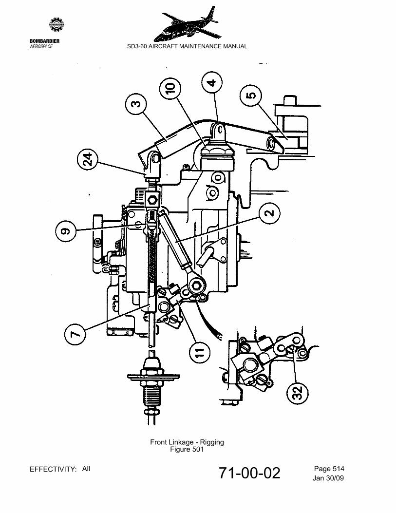
B. Rig the front linkage
Refer to Figure 501.
(1) Disconnect fuel governor reset arm (11) from fuel governor interconnecting rod (2).
(2) Rig the cased wire-rope assembly (propeller reversing system) as follows:-
(a) Back off forward sliding link (9) to detach from the clevis attachment terminal. Unscrew and retain the wire-rope ball end (split collet) thus exposed.
(b) Refer to Figure 502. Disconnect rear clevis (1) from propeller control cam (Beta). Lift clevis clear of cam and position alongside (nearest engine centreline). Withdraw rearwards sufficiently to permit sliding link (21) to be unscrewed from clevis attachment terminal. Wind exposed ball-end on wire-rope forward and re-introduce wire-rope to 'bottom out' in clevis terminal; maintain this condition and wind back ball end to seat in terminal and reconnect sliding link.
(c) Push rear clevis forward, to feed wire-rope through casing. Refit ball end retained at (a), winding back sufficiently to ensure rope 'bottoms out' when re-introduced to forward clevis attachment terminal; maintain this condition, wind ball end forward to seat in terminal and reconnect forward sliding link.
(d) Ensure that propeller reversing lever (3) is connected in the beta control valve clevis (4) and the carbon slipper block (5) is located in the propeller low stop collar.
(e) Refer to Figure 502. Place flight compartment POWER lever and consequently the follower lever (15) in a mid travel position between FLIGHT IDLE and max. power.
(f) Refer to Figure 502. Reconnect rear clevis (1) to the 3rd hole from the top in the propeller cam (Beta) (23). Check clevis end is in safety (through inspection hole).
(g) Disconnect forward clevis (24) from the propeller reversing lever (3).
NOTE: A sliding spacer is installed in the attachment hole. Do not lose when disconnecting.
Jan 30/0971-00-02 Page 514EFFECTIVITY: All
zSD3-60 AIRCRAFT MAINTENANCE MANUAL
Front Linkage - RiggingFigure 501
Jan 30/0971-00-02 Page 515EFFECTIVITY: All
zSD3-60 AIRCRAFT MAINTENANCE MANUAL
(h) Pull forward firmly on front sliding link (9) to eliminate cable backlash and adjust clevis end (24) such that when re-aligned with pick-up hole (spacer re-fitted) in reversing lever (3), the slot end face of the beta control clevis (4) is flush with the beta valve stop nut (10).
NOTE: Ensure clevis end (24) is in safety (through inspection hole).
(3) Adjust length of fuel governor interconnecting rod (2) to exactly align hole through it with the outer hole through fuel governor reset arm (11). Shorten the interconnecting rod by ½ turn and reconnect.
(4) Tighten nuts and appropriately lock (cotter pins/lockwire).
C. Rig the rear linkage
Refer to Figure 502.
NOTE: 1. The power control rear linkage comprises the linked assemblies between the FCU and the power input cambox.
2. The FCU is substantially pre-rigged by the engine manufacturer; this minimizes pre-engine run rigging activity. However, to cater for cases where an FCU is replaced, some overlap as between operator and manufacturer rigging checks is catered for.
(1) If FCU has been replaced, check:-
FCU interconnect rod (12) is set to nominal length of 8.25 in. and is connected between the outer hole in arm (18) and the third hole from the top in FCU activating lever (20).
(2) Disconnect control cable from power input lever (33).
(3) Check for free movement of input lever (33) between flight idle and max. power (FCU max. forward stop contacted). Return to flight idle and insert rigging pin in cambox assembly to maintain flight idle.
(4) Check that input lever (33) is installed on cambox shaft (16) at 5 to 10° below horizontal; if necessary, remove and re-install to comply.
(5) Move flight compartment POWER lever to FLIGHT IDLE and apply friction lock.
(6) Adjust the Bowdenflex cable terminal as necessary (with backlash removed in tension) and reconnect to power input lever (33) without straining.
NOTE: It is essential to ensure cable is correctly aligned i.e. 'I' and 'O' idents are positioned as illustrated.
(7) Remove rigging pin from the cambox. Release friction lock and exercise flight compartment POWER lever between FLIGHT IDLE and max. power, back and forth; check that movement is free with no tendency to bind.
Jan 30/0971-00-02 Page 516EFFECTIVITY: All
zSD3-60 AIRCRAFT MAINTENANCE MANUAL
(8) With POWER lever held fully forward (FCU on max. forward stop), adjust console max. power stop to contact lever, then back-off by ½ turn.
NOTE: Forward power range of rear linkage is now rigged.
(9) Disconnect clevis (24) from propeller reversing lever (3). Refer to Figure 501.
(10) Refer to Figure 501. With flight compartment POWER lever at FLIGHT IDLE:-
(a) Locate ferrule (7) and apply a pencil mark to wire-rope sleeving a distance of 0.65 in. aft of rear end of ferrule.
(b) Operate POWER lever slowly to reverse, arresting immediately the rear of ferrule (7) is coincident with mark applied at (a).
(c) Maintain condition (b) and set console reverse stop to contact POWER lever.
NOTE: With the POWER lever held on reverse stop, it should lie approximately midway between the ground fine gate and the rear of the cam track.
Refer to Figure 502. To increase movement beyond ground fine, if necessary, progressively drop clevis (1) down a hole in propeller control cam (Beta) (23) to increase POWER lever travel and repeat step (10).
(11) Refer to Figure 501. Return POWER lever to FLIGHT IDLE and reconnect clevis (24) to propeller reversing lever (3).
CAUTION: WITH THE REVERSING LINKAGE NOW CONNECTED, ON NO ACCOUNT SHOULD ATTEMPT BE MADE TO SELECT POWER LEVER BELOW FLIGHT IDLE WITH THE ENGINE INOPERATIVE. SUCH ACTION WILL CAUSE DAMAGE TO BE SUSTAINED BY THE REVERSING LINKAGE.
(12) Ensure that all nuts and joints are tight and appropriately locked (cotter pins/lockwire).
NOTE: IMPORTANT If any further adjustments are made following subsequent engine run, the following aspects of the rigging should be re-checked:-
(a) Front linkage adjustments i.e. prop governor reset arm and beta valve.
(b) Max. forward position of the flight compartment POWER lever causes the FCU arm (18) to contact the max. forward stop.
Jan 30/0971-00-02 Page 517EFFECTIVITY: All
zSD3-60 AIRCRAFT MAINTENANCE MANUAL
Rear Linkage - RiggingFigure 502
Jan 30/0971-00-02 Page 518EFFECTIVITY: All
zSD3-60 AIRCRAFT MAINTENANCE MANUAL
D. Check power control deadband (FLIGHT IDLE to GROUND FINE).
NOTE: This need only be performed if asked for following an unsatisfactory Flight Idle Ng check.
(1) Refer to Figure 502. Disconnect rear clevis (1) from propeller control cam (beta) (23).
(2) Using a protractor on the cambox input lever (33), measure the deadband as follows:-
(a) From FLIGHT IDLE, pull flight compartment POWER lever slowly towards reverse until FCU lever (18) moves off the deadband stop. Then advance slowly until a 0.003 in. feeler gauge is gripped tightly between the deadband stop and adjustment screw (such that any further motion in the reverse direction would release the feeler). Maintain this setting.
(b) Measure the angle of the cambox input lever.
(c) Push the POWER lever forward to a point where the deadband screw is again about to lift off the stop but will still grip the feeler tightly. Maintain this setting.
(d) Measure the cambox input lever angle.
NOTE: 1. The total angular travel from step (a) to (d) should be 20 ± 1°. If not, adjust the deadband stop screw to obtain correct deadband.
2. The deadband should be positioned such that point (2) (b) occurs at or just behind (towards reverse) the GROUND FINE detent on the POWER lever and point (2) (d) occurs at or just ahead of (towards max. power) FLIGHT IDLE.
3. The deadband may be repositioned by adjusting the serrated washer on the FCU arm (18). A movement as little as ± 0.6° is possible in the position of the arm. Finer adjustments may be made by lengthening or shortening the interconnect rod (12). If more than 2 turns on the rod are required, the adjustment should be made on the serrated washer.
4. If it is impossible to position the deadband between FLIGHT IDLE and GROUND FINE (because of excess cable slop for example), it is permissible to slightly widen the deadband. However, the deadband should not extend more than 1° forward of FLIGHT IDLE or 1° aft of GROUND FINE.
(3) Reconnect rear clevis (1) to propeller control cam (beta) (23).
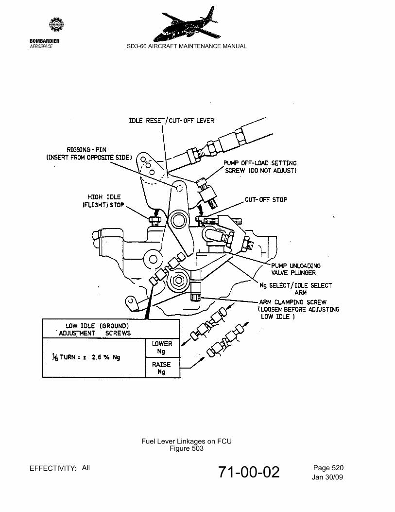
E. Rig the FUEL lever linkage
Refer to Figure 503.
NOTE: The low idle (GROUND) adjustment screws are only to be reset if required following an engine check run of Flight Idle Ng.
Jan 30/0971-00-02 Page 519EFFECTIVITY: All
zSD3-60 AIRCRAFT MAINTENANCE MANUAL
(1) Disconnect control cable terminal from idle reset/cut-off lever.
(2) Insert rigging pin in the idle control linkage to set it for ground idle position.
(3) Place flight compartment FUEL lever in GROUND position. Align FUEL lever cable terminal with third hole from top in the FCU idle reset/cut-off lever and connect. Remove rigging pin.
(4) Operate FUEL lever throughout full range to ensure freedom of movement, then check:-
(a) When selected OFF, the FCU cut-off stop is contacted and the pump off-load setting screw fully depresses the unloading valve plunger.
(b) When selected to GROUND, the FCU rigging pin can be inserted and withdrawn freely.
(c) When selected to FLIGHT, FCU idle reset/cut-off lever contacts high idle stop.
F. Rig the propeller lever linkage
Refer to Figure 504.
(1) Move the console PROP lever fully forward and check that range skirt below the prop governors speed select lever has contacted the maximum speed stop.
NOTE: If necessary, adjust console stop to comply.
(a) Move console PROP lever to FEATHER and adjust cable terminal where attached to governors speed select lever such that range skirt full depresses the feathering valve plunger.
Jan 30/0971-00-02 Page 520EFFECTIVITY: All
zSD3-60 AIRCRAFT MAINTENANCE MANUAL
Fuel Lever Linkages on FCUFigure 503
Jan 30/0971-00-02 Page 521EFFECTIVITY: All
zSD3-60 AIRCRAFT MAINTENANCE MANUAL
Propeller Lever Linkage - Prop GovernorFigure 504
Jan 30/0971-00-02 Page 522EFFECTIVITY: All
zSD3-60 AIRCRAFT MAINTENANCE MANUAL
7. Rigging Checks and adjustments
A. General
This paragraph details various engine and propeller rigging checks which are performed with the engine/s running. Each check details:-
(1) Lever settings at console.
(2) Corresponding required observations.
(3) Significance of actual observations.
(4) Remedial adjustment.
WARNING: ENSURE ENGINE/S ARE SHUTDOWN BEFORE PERFORMING ANY ADJUSTMENTS ON ENGINE-MOUNTED EQUIPMENT. THIS IS ESSENTIAL DUE TO CLOSE PROXIMITY OF PROPELLER AND EXHAUST NOZZLES.
B. Check flight fine pitch angle.
(1) Console Controls
(2) Observe:
Refer to Figure 505. Torque indications agree with that obtained the referred figure for the prevailing conditions within a tolerance band of ± 150 lb.ft.
NOTE: Observations outside tolerance band may be the result of large errors in the torque indication system. Check calibration. Refer to 77-11-00, pb201.
(3) Significance:
(a) Torque less than required value means blade angle too fine.
(b) Torque more than required value means blade angle too coarse.
(4) Adjustments:
(a) Torque low:-
Ground/Air lever Ground/AirFUEL levers GROUNDAir conditioning engine bleed switches OFFPROP levers Full forwardPOWER levers Advance to obtain 1450 propeller RPM.
Jan 30/0971-00-02 Page 523EFFECTIVITY: All
zSD3-60 AIRCRAFT MAINTENANCE MANUAL
Refer to Figure 501. Check that rear of slot in clevis (4) is flush with the front face of cap nut (10) on propeller governor. If not, make adjustment on front end clevis (24) to achieve this.
Then, to increase torque by a small amount, wind out front end clevis (24) by a ½ turn from the position that flushes the clevis slot with the front face of cap nut previously referred to.
(b) Torque low:-
Refer to 61-10-01, Figure 203. If the preceding adjustments are not sufficient, blades must be coarsened by winding elastic nuts (pitch adjustment) Pt. No. A-2043 towards engine. Adjust all three nuts the same, 1 flat on nut = 35 lb.ft. approx.
(c) Torque high:-
Refer to Figure 501. Check that rear of slot in clevis (4) is flush with front face of cap nut (10) on propeller governor. If not, make adjustment on front end clevis (24) to achieve this. Then to decrease torque by a small amount, wind in front end clevis (24) by a ½ turn from the position that flushes the clevis slot with the front face of cap nut previously referred to.
(d) Torque high:-
Refer to 61-10-01, Figure 203. If the preceding adjustment is no sufficient, blades must be fined by winding elastic nuts (pitch adjustment) Pt. No. A-2043 forward. Adjust all three nuts the same. 1 flat on nut = 35 lb.ft. approx.
(5) Remarks
(a) Adjustments greater than ½ turn on front end clevis (24) from the position that flushes the clevis slot with front face of cap nut are not permitted.
Flight fine pitch angle must be correct before checking reverse. Too fine flight fine pitch angle makes angle in reverse too coarse relative to the other engine and vice versa.
Jan 30/0971-00-02 Page 524EFFECTIVITY: All
zSD3-60 AIRCRAFT MAINTENANCE MANUAL
Flight Idle Torques (at 1450 RPM and zero airspeed)Figure 505
Jan 30/0971-00-02 Page 525EFFECTIVITY: All
zSD3-60 AIRCRAFT MAINTENANCE MANUAL
C. Check Flight Idle Ng
(1) Console Controls
(2) Observe
(a) Flight Idle Ng 71% ± 1% on both engines.
(b) Prop RPM:
1 950 ± 20 (air cond. OFF)
2 greater than 900 (air cond. ON)
(3) Significance
(a) If Ng is above 72%, either:-
1 Rigging is holding FCU on a higher setting.
2 Low idle adjustment screws are incorrectly set.
3 Deadband adjustment screw is in physical contact with idle select cam (no 0.003 in. gap).
(b) If Ng is below 70% either:-
1 PROP lever is inadvertently set in FEATHER range.
2 Py air is bleeding through loose connection in P3 or Py line.
3 Low idle adjustment screws are incorrectly set.
(4) Adjustments:
(a) Ng high (in order of precedence).
1 Check that rigging is not holding FCU on high setting. Refer to Figure 502. With POWER lever at FLIGHT IDLE it should be possible to insert the rigging pin in cam follower (15). If necessary, adjust Bowdenflex cable terminal to enable rigging pin insertion. Remove rigging pin.
Ground/Air lever Ground/AirFUEL levers GROUNDPROP levers Taxi RPMPOWER levers FLIGHT IDLEAir cond. engine bleed switches OFF
Jan 30/0971-00-02 Page 526EFFECTIVITY: All
zSD3-60 AIRCRAFT MAINTENANCE MANUAL
2 Reset low idle adjustment screws in required direction and amount to drop low idle speed to within tolerance. Refer to Figure 503.
3 Check power control deadband and adjust as necessary (refer to para. 6.D.).
(b) Ng low (in order of precedence)
1 Check that PROP lever is out of FEATHER position.
2 Check that P3 and Py line connections are tight.
3 Reset low idle adjustment screws in required direction and amount to raise low idle speed to within tolerance. Refer to Figure 503.
(c) Prop RPM high/low
NOTE: Instructions or values presented to the left or right of oblique strokes in the following, respectively relate to corrective action for RPM high and low.
Reduce/increase Ng to 70%/72% as detailed in adjustment (a) 2 / (b) (c). (a ½% Ng change will appropriately reduce/increase Np by approximately 10 RPM).
D. *Check High Idle Ng
(1) Console Controls
(2) Observe:
High idle Ng 79% +1 -0 on both engines.
(3) Significance
(a) Refer to Figure 503. If Ng is above 80%, high idle stop is wound in too far.
(b) Refer to Figure 503. If Ng is below 79%, high idle stop is wound out too far.
(4) Adjustments:
(a) Ng high - Set high idle adjustment anti-clockwise. 1 turn on adjustment = 1.9% approx.
Ground /Air lever Ground/airFUEL levers FLIGHTPROP levers Taxi RPMPOWER levers FLIGHT IDLEAir cond. engine bleed switches OFF
Jan 30/0971-00-02 Page 527EFFECTIVITY: All
zSD3-60 AIRCRAFT MAINTENANCE MANUAL
(b) Ng low - Set high idle adjustment clockwise. 1 turn on adjustment = 1.9% approx.
NOTE: Where insufficient adjustment is available, it is permissible to increase Ng by adjusting roller assembly on the idle select arm. Refer to Figure 503. After any such adjustment, set high idle stop in contact with idle reset lever.
E. Check Ng pick-up forward from flight idle.
(1) Console Controls
(2) Observe:
(a) Distance moved by POWER levers is between 1/8 and 1/4 in. before Ng picks up.
(b) Ng pick-up simultaneous on both engines with both POWER lever knobs together (observe small needles on Ng gauges).
(3) Significance:
(a) Refer to Figure 502. No free movement (1/8 to 1/4 in.) of a POWER lever before Ng picks up means FCU control rod (12) is too short and is holding FCU on high setting.
(b) Pick-up not simultaneous means pick-up deadbands (system elasticity) is different both sides.
(4) Adjustments:
(a) No free movement (1/8 to 1/4 in.) of POWER lever before Ng picks up; lengthen control rod (12) as required.
(b) Pick-up not simultaneous; lengthen rod (12) for the engine which picks up early.
(5) Remark:
It is important that Ng pick-up is simultaneous on both engines to avoid POWER lever stagger.
Ground/Air lever Air/GroundFUEL levers GROUNDPROP levers Full forwardPOWER levers Move both knobs together very slowly
forward from FLIGHT IDLE.
Jan 30/0971-00-02 Page 528EFFECTIVITY: All
zSD3-60 AIRCRAFT MAINTENANCE MANUAL
F. Check power lever stagger
(1) Console Controls
(2) Observe:
Amount of POWER lever stagger at the knobs for same torque on both engines. Check if stagger is constant throughout the range or progressively increasing.
(3) Significance:
A constant amount of stagger throughout the operative range is indicative of unequal deadbands in the power control circuit.
A progressively increasing stagger between the two power levers means that the geometry of the rear linkage is such that more console lever movement is required on one side to achieve the same angular movement of the FCU arm (18) on both engines. Refer to Figure 502.
(4) Adjustments:
(a) For constant stagger, perform adjustment (2) of para. 7.E.
(b) For progressively increasing stagger, perform adjustment (1) and then make the following adjustment for the power lever ahead:-
1 Use marker pen to mark FCU arm and serrated spacer original position before making adjustments.
2 Rotate FCU arm (18) anti-clockwise using serrated spacer. One big serration anticlockwise and one small serration clockwise equals net anticlockwise movement of 0.6 degrees.
3 Refer to Figure 502. Lengthen the FCU control rod (12) to suit.
(c) Make the following adjustments for the power lever behind:-
1 Repeat preceding 1.
2 Repeat preceding 2 and 3, adjusting in the opposite sense to that quoted.
Ground/Air lever Ground/AirFUEL levers GROUNDAir cond. engine bleed switches OFFPROP levers Full forwardPOWER levers Advance to pull same torque on both
engines (1500 to 3000 ft. lb.)
Jan 30/0971-00-02 Page 529EFFECTIVITY: All
zSD3-60 AIRCRAFT MAINTENANCE MANUAL
(5) Remarks:
If progressively increasing stagger persists following performance of adjustment (2), then it is permissible to alter the hole pick-up at either end of FCU control rod (12) on one engine to attain corresponding POWER lever to FCU arm angular movement on both engines.
NOTE: Before resorting to this action, check that airframe rigging is correct. Refer to 76-10-00, pb501.
G. Check reverse Ng Droop
(1) Console Controls
(2) Observe:
(a) Propeller speeds rise to and steady between 1050-1120 prpm with Ng constant.
(b) Once steady state beta propeller speed is reached, Ng droops to not less than 60% and then rises.
(3) Significance:
(a) Refer to Figure 501. Steady state prpm too high means that the propeller governor reset adjusting screw (32) is set incorrectly, the airbleed linkage, items (2) and (11) is not resetting the governor for beta range operation.
(b) Excessive Ng droop means that propeller governor or reset is too great, or power levers were moved too fast.
(4) Adjustments:
(a) Steady state prpm too high:-
1 Check attachment of fuel governor interconnecting rod (2) and reset arm (11) - Figure Refer to Figure 501.
2 Adjust reset screw (32) clockwise to reduce prpm.
(b) If Ng droops to below 60%, then:-
Ground/Air lever GroundFUEL levers GROUNDAir cond. engine bleed switches OFFPROP levers Taxi RPMPOWER levers Together slowly from FLIGHT FINE into
REVERSE.
Jan 30/0971-00-02 Page 530EFFECTIVITY: All
zSD3-60 AIRCRAFT MAINTENANCE MANUAL
1 Make power lever selections more slowly and re-check.
2 Refer to Figure 501. If 1 ineffective, adjust reset screw (32) anti-clockwise.
H. Check Reverse Max. Power
(1) Console Controls
(2) Observe:
(a) Propeller speeds rise to and steady between 1580 and 1650 prpm.
(b) Torque in range 700-800 lb.ft. is achieved.
(c) POWER lever positions.
NOTE: Mark to facilitate post-shut-down adjustment of console reverse power stops (i.e. to contact power levers at the marked positions).
(3) Significance:
(a) Reverse propeller speed too high means:-
1 Refer to Figure 501. Airbleed link, items (2) and (11) is not resetting the propeller governor.
2 governor reset adjusting screw (32) is set incorrectly.
3 Refer to Figure 504. governor max. speed stop is incorrectly set.
(b) Reverse propeller speed too low means max. reverse power is FCU input limited.
(c) Max. indicated reverse torque not achievable may be due to incorrectly set console stops or torque indication system error.
(4) Adjustments:
(a) If reverse propeller speed is too high:-
1 Refer to Figure 501. Check attachment of airbleed link, items (2) and (11) on.
Ground/Air lever GroundFUEL levers GROUNDAir conditioning engine bleed switches OFFPROP levers Full forwardPOWER levers Together slowly from FLIGHT IDLE
towards REVERSE.
Jan 30/0971-00-02 Page 531EFFECTIVITY: All
zSD3-60 AIRCRAFT MAINTENANCE MANUAL
2 Check max. propeller speed in the forward power range (1675 +25 -0 prpm)
3 Refer to Figure 501. Adjust reset screw (32) clockwise to reduce prpm.
(b) If reverse propeller speed is too low, wind in FCU max. reverse stop one turn at a time and re-check.
(c) If required torque not achievable:-
1 Check console stops are not restricting.
2 If any adjustment following 1 is ineffective, calibrate torque indication system and repeat check taking account of established indication error.
I. Max-taxi balk check
(1) Console Controls
8. Systems Checks (Engines running)
A. Reserve power system
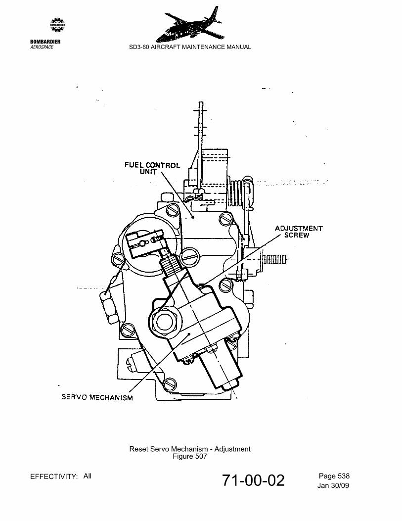
POWER levers FLIGHT IDLEControls lock lever LOCKEDPOWER levers Advance to balked position and check that
Ng (left and right) is less than 87% Record obtained values on proforma. Refer to Figure 509.
POWER levers FLIGHT IDLEPROP levers Taxi RPMFUEL levers FLIGHTAir Cond. bleed switches ON (in-line)Reserve Power L & R ARMReserve Power Test L & R (each engine in turn)
TEST and hold, check:-RTOP indicator display ON Ng increases approx. 4% Air-cond. bleed switches, `off-line'.Release, check conditions revert to pre-test.
Reserve Power L&R OFFFUEL levers GROUND
Jan 30/0971-00-02 Page 532EFFECTIVITY: All
zSD3-60 AIRCRAFT MAINTENANCE MANUAL
B. Low blade angle secondary stop and blade pitch indication.
First engine:-
C. Auto-feather system
D. Propeller overspeed governor test
First engine:-
PROP lever Taxi RPMPOWER lever FLIGHT IDLEGround/air lever GroundLBA TEST switch Press and holdPOWER lever Move slowly into ground range until FINE
PITCH light comes on (approx. 0.5 in). Check that light cycles with fluctuating prpm. Select FLIGHT IDLE Release test switch. Select REVERSE. Check that REVERSE PITCH light comes on. Select GROUND FINE. Check that REVERSE PITCH light extinguishes. FLIGHT IDLE.
Repeat for second engine:
PROP levers Taxi RPMPOWER levers FLIGHT IDLEANTI-ICE VANE switches OFF (NORMal indicated)AUTO FEATHER TEST switches TEST and hold:
AUTO FEATHER ARM captions lit prpm decreases significantly and hunts.Anti-ice vane indicators ANTI-ICE.Release:Autofeather indicators 'out' prpm increases to original value.Anti-ice vane indicators NORMAL.
Prop lever Max. prpmPOWER lever Set to give 1620 prpmOVERSPEED GOVERNOR TEST switch Press and hold, prpm drops to 1565±30.
Release. Prpm slowly increases to 1620.POWER lever FLIGHT IDLEPROP lever Taxi RPMRepeat for second engine:
Jan 30/0971-00-02 Page 533EFFECTIVITY: All
zSD3-60 AIRCRAFT MAINTENANCE MANUAL
E. Maximum propeller speed check
F. Air-conditioning system
Post engine installation check is incorporated in the Flight Idle Ng check (para. 7.C.); for the running condition, this essentially comprises a check of propeller speed with air-conditioning OFF then ON.
G. Fuel system
H. Fuel Manifold Purge System:
During shutdown, check that there is no evidence of:-
(1) visible fuel fume emission from exhaust stubs
(2) raw fuel drainage from plenum drains
NOTE: During rundown, injection of purged fuel may cause an ITT rise of approx. 100°C for 1 second duration; this has no adverse effect on the engine.
Flying control locks disengaged.PROP levers Full forwardPOWER levers Advance to obtain max. stabilised prpm 1675
(observe prpm remains stabilised within + 25, - 0 prpm).
PROP levers Max. RPMPOWER levers Refer to Figure 506. Set to provide torque for
the airfield conditions of OAT and pressure altitude.
CROSSFEED VALVE lever. OPEN.BOOSTER PUMP switches OFF in turn for approx. 5 secs., then ON.
Check:Engines operate normally, FUEL L & R low pressure lights remain unlit.
CROSSFEED VALVE lever SHUTBOOSTER PUMP switches OFF together for approx. 5 secs. then ON
Check:Engines operate normally FUEL pressure warning lights, L & R, illuminate and then go out when switches are returned to ON positions.
Jan 30/0971-00-02 Page 534EFFECTIVITY: All
zSD3-60 AIRCRAFT MAINTENANCE MANUAL
9. Engine Performance Checks
Checks A. through E. are performed as required after engine installation, engine rigging adjustment or powerplant component change.Checks F. through H. are performed as scheduled by the Aircraft Maintenance Programme.
NOTE: (1) The checks detailed should not be confused with the ‘Engine Condition Trend Monitoring System'. Refer to 77-13-00, pb1.
(2) It is recommended that flaps be lowered to 30° during performance checks.
A. Perform Static Reduced Power Check
This check is performed on both engines after (a) an engine is installed (b) after an engine rigging adjustment (c) subsequent to propeller or engine component changes or (d) if specifically requested by flight crew.
NOTE: The test must be carried out with generators OFF, engine anti-icing vanes retracted and all engine bleeds OFF.
Procedure
(1) Establish airfield conditions of pressure altitude and OAT.
(2) Refer to Figure 506. Enter the two graphs presented at the prevailing OAT and where intersection occurs with the appropriate pressure altitude, read off to the left:-
(a) Torque setting at which test is to be conducted.
(b) The corresponding target value of ITT (°C).
Record these values on the Ground Run Check Sheet. Refer to Figure 509.
(3) Start and run engines and allow to stabilize.
(4) Set PROP levers fully forward and advance POWER levers to obtain recorded torque setting. Allow to stabilize for one minute.
(5) From engine instruments, record ITT on Ground Run Check Sheet.
(6) Check that observed values of ITT agree (within limits) with the target value obtained. Refer to Figure 506.
NOTE: If results are outside quoted limits, do not make adjustments (perform Static Maximum Power Check, para. B., followed by any necessary adjustments relative to that check).
A static maximum take-off power check is carried out subsequent to a reduced power check following installation of an engine.
NOTE: Thereafter, the check is only applied when loss of performance is suspected by ground engineer or as reported by flight crew.
Procedure:
(1) Establish airfield conditions of pressure altitude and OAT.
(2) Refer to Figure 508 (Sheet 1). Refer to Figure 508 (Sheet 2). Enter the four graphs presented at the prevailing OAT and where intersection occurs with the appropriate pressure altitude, read off to the left:-
(a) Torque setting at which test is to be conducted.
(b) The corresponding target values of Fuel Flow (lb/hr) Ng (%) and ITT (°C).
Record these values on the Ground Run Check Sheet. Refer to Figure 509.
(3) Start and run the engine(s) subject to check and allow to stabilize.
(4) Set PROP lever fully forward and advance POWER lever to obtain recorded torque setting. Allow to stabilize for one minute.
NOTE: Time spent on maximum power should not exceed two minutes.
(5) From engine instruments, record Fuel Flow, Ng and ITT on Ground Run Check Sheet.
(6) Check that observed values of Fuel Flow, Ng and ITT agree with the target values within tolerances. Refer to Figure 508 (Sheet 1). Refer to Figure 508 (Sheet 2).
NOTE: (a) If results are outside quoted limits, or ITT is within 5°C of top tolerance, then as an initial course of action:-
1. Perform torque calibration check. Refer to 77-11-00, pb201. Establish particularly the amount of sensing (±) of indicator error for a 50 psi input (this should be within ± 45 lb. ft.).
2. Repeat static MTOP check, taking account of known indicated error when setting up test torque; check will be confirmed satisfactory if observed values for Fuel Flow, Ng and ITT and now found to agree with target values within tolerances quoted. Refer to Figure 508 (Sheet 1). Refer to Figure 508 (Sheet 2).
Jan 30/0971-00-02 Page 537EFFECTIVITY: All
zSD3-60 AIRCRAFT MAINTENANCE MANUAL
(b) Where check remains unsatisfactory following the actions defined in (a), investigate cause and take remedial action with respect to OPERATING & PERFORMANCE CHECK PROBLEMS (detailed in Chap. 72 of the Pratt & Whitney Maintenance Manual, Pt No. 3032842).
NOTE: IMPORTANT: WHERE REFERRED REMEDIAL ACTIONS TO RETURN WITHIN TOLERANCES ARE EXHAUSTED WITHOUT EFFECT, REQUEST AIRCREW PERFORM STATIC RTOP CHECK (DETAILED IN CREW MANUAL, SECT. 4, CHAP 4-04AR). FOR ASSESSMENT OF RESULTS - REFER TO PARA. C.
(7) Return POWER lever/s to FLIGHT IDLE.
C. Static RTOP Check Assessment
(1) Enter aircrew supplied data on the Ground Run Check Sheet.
(2) Enter RTOP target values for ITT and Ng on the Ground Run Check Sheet.
NOTE: Refer to Figure 508 (Sheet 1). Refer to Figure 508 (Sheet 2). Target values are established with reference to the Static Max. Torque Check Chart as follows:-
(3) Check that achieved values of ITT and Ng concur with the target values within the undernoted tolerances:-
NOTE: If the performance characteristics do not comply with requirements, including tolerances, request aircrew perform a flight power check (setting AFM torque appropriate to thermodynamic power limits, less 45 lb.ft. fleet mean performance).
Only if the in-flight power assurance check shows the engine to be ITT limited should the engine be rejected.
(a) Add 35°C to scheduled ITT ) for conditions(b) Add 2.5% to scheduled Ng. ) under which RTOP static
check was conducted.
ITT Ng
+ 0°C + 0.5%-50°C - 3.5%
Jan 30/0971-00-02 Page 538EFFECTIVITY: All
zSD3-60 AIRCRAFT MAINTENANCE MANUAL
Reset Servo Mechanism - AdjustmentFigure 507
Jan 30/0971-00-02 Page 539EFFECTIVITY: All
zSD3-60 AIRCRAFT MAINTENANCE MANUAL
D. Perform Reserve Power Check.
This check is performed as a 'follow-up' to a satisfactory static MTOP/RTOP check as appropriate.
NOTE: 1. The check is performed with generator OFF, engine anti-icing vanes retracted and all bleeds OFF.
2. It is presumed opposite engine is stopped/operating below 1000 lb. ft. torque during check.
Procedure
(1) Obtain static armed torque (Refer to Figure 506) and static maximum torque values (Refer to Figure 508 (Sheet 1)) for the prevailing conditions of pressure altitude and OAT. Enter these values on the Ground Run Check Sheet.
(2) Set up static armed torque. Allow engine to stabilize for one minute.
(3) Select appropriate RESERVE POWER control switch on panel 4P to ARM and check that the target static maximum torque is achieved automatically within the tolerance quoted. Refer to Figure 508 (Sheet 1).
NOTE: If outside quoted tolerances, note obtained value and actual Ng rise. Shutdown engine and appropriately adjust the Ng reset servo mechanism as detailed in para. E.
E. Adjust Ng Reset Servo Mechanism
If the target static maximum torque was not achieved within tolerance during reserve power check (para. D.), then employ the Ng reset adjustment screw (Refer to Figure 507.) to improve the situation. Turn screw anti-clockwise to increase reset and thus torque or clockwise to reduce reset and thus torque.
NOTE: (1) An adjustment of one turn will change Ng by approximately 0.4%.
(2) Refer to Figure 506. Refer to Figure 508 (Sheet 1). Refer to Figure 508 (Sheet 2). Comparison of the actual reset achieved during check as against that projected between referenced figures will give some indication of 'which way to go' and by how much.
(3) After any adjustment, repeat the reserve power check.
Jan 30/0971-00-02 Page 540EFFECTIVITY: All
zSD3-60 AIRCRAFT MAINTENANCE MANUAL
Static Maximum Torque CheckFigure 508 (Sheet 1)
Jan 30/0971-00-02 Page 541EFFECTIVITY: All
zSD3-60 AIRCRAFT MAINTENANCE MANUAL
Static Maximum Torque CheckFigure 508 (Sheet 2)
Jan 30/0971-00-02 Page 542EFFECTIVITY: All
zSD3-60 AIRCRAFT MAINTENANCE MANUAL
F. Power Lever Movement Check
NOTE: This check must be performed before the static reduced to MTOP power check.
Procedure:
WARNING: ENSURE THAT THE ENGINE IS SHUT DOWN BEFORE PERFORMING ANY ADJUSTMENTS ON ENGINE MOUNTED EQUIPMENT. THIS IS ESSENTIAL DUE TO THE CLOSE PROXIMITY OF PROPELLER AND EXHAUST NOZZLES.
(1) Remove access panel 410AL (left engine) or 410AR (right engine) to gain access to the fuel control unit (FCU). Refer to 6-30-00, Figure 8.
(2) Move the flight compartment left power lever to the maximum position and ensure that the FCU lever is hitting the maximum stop.
NOTE: If required, adjust the rigging to achieve this condition, as detailed in para. 6.C.
(3) Repeat the previous step for the opposite engine, reading right for left as applicable.
G. Perform Static Reduced to MTOP Power Check
NOTE: The Power Lever Movement Check (para. F.) must be performed before proceeding with this check.
Procedure:
CAUTION: THIS TEST MUST BE PERFORMED WITH GENERATORS OFF, ENGINE ANTI-ICING VANES RETRACTED AND ALL ENGINE BLEEDS OFF
(1) Refer to Table 502. Record the airfield conditions of pressure altitude and OAT.
(2) Set the aircraft flaps to 30°.
(3) Refer to Figure 506 - Static Reduced Torque Check, and enter the co-ordinates for the prevailing OAT and Pressure Altitude on the graph.
(4) Refer to Table 502. Record the subsequent Torque setting (RESERVE POWER switch OFF) at which the test will be run.
(5) Refer to Figure 508 (Sheet 1) - Static Maximum Torque Check, and enter the co-ordinates for the prevailing OAT and Pressure Altitude on the graph.
(6) Refer to Table 502. Record the subsequent Torque (ARM) value due to be obtained.
NOTE: Make sure that the above results are recorded just before each Static Reduced to MTOP Power Check engine run.
(7) Start and run the engines and allow them to stabilise. Refer to para. 2.
Jan 30/0971-00-02 Page 543EFFECTIVITY: All
zSD3-60 AIRCRAFT MAINTENANCE MANUAL
(8) Make sure that the left RESERVE POWER control switch on panel 4P is set to OFF.
(9) Set the left engine propeller lever fully forward.
(10) Advance the left engine power lever to the Torque setting recorded at step (4) previous.
NOTE: Allow engine torque to stabilise.
(11) Refer to Table 502. Record the Actual Torque, Fuel Flow, Ng, ITT and PRPM from the engine instruments in the OFF column.
(12) Select the left RESERVE POWER control switch on panel 4P to ARM and confirm that the Ng increases.
(13) Refer to Table 502. Record the Actual Torque, Fuel Flow, Ng, ITT and PRPM in the ARM column.
(14) Retract the left engine power lever to Flight Idle and the left engine propeller lever to Taxi RPM.
NOTE: Select the RESERVE POWER control switch to OFF.
(15) Repeat steps (8) to (14) for the right engine reading right for left, as applicable.
(16) Set the aircraft flaps to 0°.
(17) Shut down the engines. Refer to para. 3.
Static Reduced to MTOP Power Check - ResultsTable 502
Aircraft Serial No:Tower OAT (°C):Pressure Altitude (ft):Information
sourceLH Engine RH Engine
Reserve Power Switch OFF ARM OFF ARMAMM Tables Reference Torque (lb/ft)
Recorded off Engine Indicators
Ng (%)Fuel Flow (lb/hr)ITT (°C)Actual Torque (lb/ft)Np (prpm)
CalculatedActual Torque (ARM) - Ref. Torque (ARM)% Ng Reset = Ng (ARM) - Ng (OFF)
Jan 30/0971-00-02 Page 544EFFECTIVITY: All
zSD3-60 AIRCRAFT MAINTENANCE MANUAL
(18) Refer to Figure 506. Refer to Figure 508 (Sheet 1). Compare the recorded values of Fuel Flow, Ng, and ITT obtained during the engine run, with the target values presented.
NOTE: Tolerances are also quoted on Figure 506 and Figure 508.
Any recorded anomalies are to be addressed.
(19) Refer to Table 502. Calculate and record the Actual Torque (ARM) minus the Reference Torque (ARM).
NOTE: If the value is between +100 and +200 lb.ft. replace the engine panels removed.
If the value is NOT between +100 and +200 lb.ft. Refer to para. H. for Rectification/Troubleshooting Check.
H. Rectification/Troubleshooting Check
NOTE: This procedure must be carried out if unsatisfactory results are obtained in the Static Reduced to MTOP Power Check (para. G.).
(1) If the RTOP system fails to boost, or fails to provide adequate boost, do the following:
(a) Perform a Power Lever Movement Check. Refer to para. F.
NOTE: This will ensure that the engine and airframe rigging is correct and will not interfere with the ability of the engine to achieve RTOP power.
(b) Perform the troubleshooting check. Refer to Table 503.
NOTE: The instructions in this table check that the RTOP solenoid is functioning and that the FCU Ng reset is correctly adjusted. If these two actions do not result in satisfactory operation of the RTOP system, then an FCU overhaul by an approved facility is recommended.
(c) Adjust the FCU Ng Servo valve in an anti-clockwise direction to increase torque. It is recommended that the adjustment screw is rotated in one complete turn at a time only, until the required increase in torque is achieved.
(2) If the RTOP system provides too much boost, do the following:
(a) Adjust the FCU Ng Servo valve in a clockwise direction to decrease torque. It is recommended that the adjustment screw is rotated in one complete turn at a time only, until the required decrease in torque is achieved.
Jan 30/0971-00-02 Page 545EFFECTIVITY: All
zSD3-60 AIRCRAFT MAINTENANCE MANUAL
Troubleshooting CheckTable 503
Engine Static Reduced to MTOP Check Unsatisfactory
RTOP System fails to provide adequate
boost
RTOP System fails to boost
Check for possible leak or restrictions in FCU
pneumatic system and rectify See Note (2)
Function check RTOP solenoid See Note (1)
Yes No
Is there any RTOP reset adjustment
available?
Check for possible leak or restrictions in FCU
pneumatic system (See Note 2) and rectify
Check electrical connections
No
YesAdjust RTOP reset
on FCU as detailed in para. I. (1) (c)
If required, replace solenoid
Test Test Test
Is Boost achieved?
Is Boost achieved?
Is Boost achieved?No No No
Yes Yes YesRecord Results Record Results Record Results
Overhaul FCU
NOTE: (1): This check is to be conducted with both engines shut down, aircraft electrical power ON and the Reserve Power control switch on Panel 4P selected to ARM.Operation of the Reserve Power test switch on Panel 11P will function the solenoid (an observer should hear the solenoid click as the switch is operated).
NOTE: (2): The P3 filter and associated tubing should be checked for blockage. Refer to Pratt & Whitney (Canada) Maintenance Manual, section 73-10-07.
Jan 30/0971-00-02 Page 546EFFECTIVITY: All
zSD3-60 AIRCRAFT MAINTENANCE MANUAL
Ground Run Check SheetFigure 509
Jan 30/0971-00-02 Page 547EFFECTIVITY: All
zSD3-60 AIRCRAFT MAINTENANCE MANUAL
10. Emergency Procedures
A. Engine fire
An engine fire is indicated when the fire bell sounds and the location (left and right) is identified by the illumination of the associated engines FIRE P to C module on panel lP. Additionally, the red lights in the relevant fire extinguisher buttons (panel 4P) and the fuel and *LP valve levers (centre and roof console respectively) come on.
NOTE: *On post-mod 7114 aircraft (construction Nos SH 3617 and sub) and on prior construction Nos on which Serv. Bull SD360-28-11 is incorporated, the LP FUEL lever lights only illuminate when the related FUEL lever (centre console) is set to OFF during engine shutdown.
Vital actions:
If fire warnings not out after 25 seconds
Subsequent actions:
B. Emergency shutdown
Vital actions:
Fire warning bell Cancel (Press P to C module) FUEL lever OFF PROP lever FEATHER Engine LP VALVE lever SHUT Fire extinguisher button SHOT 1Fire warnings Check out
Fire extinguisher button SHOT 2
BOOSTER PUMP switch OFFCarry out normal shutdown of other engine (if operating) as detailed in para. 3.
FUEL lever OFFPROP lever FEATHEREngine LP VALVE lever SHUT
Jan 30/0971-00-02 Page 548EFFECTIVITY: All
zSD3-60 AIRCRAFT MAINTENANCE MANUAL
Subsequent actions:
C. Engine flameout
If torque decreases and is accompanied by a fall in ITT:-
(1) Immediate action:
Perform emergency shutdown (para. B.).
(2) Subsequent action:
Investigate cause with respect to OPERATING PROBLEMS (detailed in Chap. 72 of the Pratt & Whitney Maintenance Manual Pt. No. 3032842).
D. Low oil pressure
If a low pressure warning light comes on:-
(1) Immediate actions:
(a) Check pressure gauge reading.
(b) If indicated pressure is between 60 and 90 psi reduce torque to 2000 lb.ft. maximum.
(c) If pressure is not restored (warning light extinguished) after a period of 30 seconds, perform normal shutdown (para. 3.).
CAUTION: IF OIL PRESSURE CONTINUES TO FALL BELOW 60 PSI - PERFORM EMERGENCY SHUTDOWN PARA. B.
NOTE: Fault may be of a momentary nature (eg a blocked and subsequently cleared filter) which would allow ground check run to continue.
(2) Subsequent action:
Investigate cause with respect to LUBRICATION PROBLEMS (detailed in Chap. 72 of Pratt and Whitney Maintenance Manual Pt. No. 3032842).
E. Excessive ITT
(1) Immediate action:
BOOSTER PUMP switch OFF2.Carry out normal shutdown of other engine (if operating) as detailed in para. 3.
Jan 30/0971-00-02 Page 549EFFECTIVITY: All
zSD3-60 AIRCRAFT MAINTENANCE MANUAL
Perform normal shutdown as detailed in para. 3.
(2) Subsequent action:
Investigate cause with respect to OPERATING AND PERFORMANCE CHECK PROBLEMS (detailed in Chap. 72 of Pratt & Whitney Maintenance Manual, Pt. No. 3032842).
F. Ng Overspeed
If the overspeed limits are exceeded:-
(1) Immediate action:
Perform normal shutdown as detailed in para. 3.
(2) Subsequent action:
Investigate cause with respect to OPERATING PROBLEMS (detailed in Chap. 72 of the Pratt & Whitney Maintenance Manual Pt. No. 3032842).
G. Nf Overspeed
If the overspeed limits are exceeded:-
(1) Immediate action:
Perform normal shutdown as detailed in para. 3.
(2) Subsequent action:
Investigate cause with respect to OPERATING PROBLEMS (detailed in Chap.72 of the Pratt & Whitney Maintenance Manual, Pt. No. 3032842).
Dec 18/0771-00-02 Page 551EFFECTIVITY: All
zSD3-60 AIRCRAFT MAINTENANCE MANUAL
Subsequent actions:
C. Engine flameout
If torque decreases and is accompanied by a fall in ITT:-
(1) Immediate action:
Perform emergency shutdown (para. B.).
(2) Subsequent action:
Investigate cause with respect to OPERATING PROBLEMS (detailed in Chap. 72 of the Pratt & Whitney Maintenance Manual Pt. No. 3032842).
D. Low oil pressure
If a low pressure warning light comes on:-
(1) Immediate actions:
(a) Check pressure gauge reading.
(b) If indicated pressure is between 60 and 90 psi reduce torque to 2000 lb.ft. maximum.
(c) If pressure is not restored (warning light extinguished) after a period of 30 seconds, perform normal shutdown (para. 3.).
CAUTION: IF OIL PRESSURE CONTINUES TO FALL BELOW 60 PSI - PERFORM EMERGENCY SHUTDOWN PARA. B.
NOTE: Fault may be of a momentary nature (eg a blocked and subsequently cleared filter) which would allow ground check run to continue.
(2) Subsequent action:
Investigate cause with respect to LUBRICATION PROBLEMS (detailed in Chap. 72 of Pratt and Whitney Maintenance Manual Pt. No. 3032842).
E. Excessive ITT
(1) Immediate action:
BOOSTER PUMP switch OFF2.Carry out normal shutdown of other engine (if operating) as detailed in para. 3.
Dec 18/0771-00-02 Page 552EFFECTIVITY: All
zSD3-60 AIRCRAFT MAINTENANCE MANUAL
Perform normal shutdown as detailed in para. 3.
(2) Subsequent action:
Investigate cause with respect to OPERATING AND PERFORMANCE CHECK PROBLEMS (detailed in Chap. 72 of Pratt & Whitney Maintenance Manual, Pt. No. 3032842).
F. Ng Overspeed
If the overspeed limits are exceeded:-
(1) Immediate action:
Perform normal shutdown as detailed in para. 3.
(2) Subsequent action:
Investigate cause with respect to OPERATING PROBLEMS (detailed in Chap. 72 of the Pratt & Whitney Maintenance Manual Pt. No. 3032842).
G. Nf Overspeed
If the overspeed limits are exceeded:-
(1) Immediate action:
Perform normal shutdown as detailed in para. 3.
(2) Subsequent action:
Investigate cause with respect to OPERATING PROBLEMS (detailed in Chap.72 of the Pratt & Whitney Maintenance Manual, Pt. No. 3032842).