SDG6181P13/09 Oil India Limited (A Govt. of India Enterprise) P.O. Duliajan – 786602, Assam Telephone No. (91-374) 2800491 Fax No: (91-374) 2800533 Email: [email protected]; [email protected]Tender No. : SDG6181P13/09 Tender Fee : INR 4,500.00 OR USD 100.00 Bid Security Amount : Applicable Bidding Type : SINGLE STAGE TWO BID SYSTEM Date of pre-bid conference : 23 rd July 2012 Venue of pre-bid conference : GUWAHATI, ASSAM (INDIA) Performance Guarantee : Applicable OIL INDIA LIMITED invites Global Tenders for items detailed below: Item No. / Mat. Code Material Description Unit Qty 1. HIGH PERFORMANCE COMPUTING CENTRE (HPCC) (DETAILED SPECIFICATION ETC. HAS BEEN FURNISHED VIDE SECTION - 1). NO 1 NOTES: (1) A Pre-Bid Conference with the Parties will be held in Guwahati (India) on 23 rd July, 2012 to discuss on the technical specifications and other terms and conditions of the tender. All the Parties who purchase the Tender Document within the closing date of sale of the tender will be eligible to attend the Pre-Bid Conference. The exact venue and time of the Pre-Bid conference will be intimated to the Parties at a later date. (2) Clarification on the technical specifications and other terms & conditions of the High Performance Computing Centre shall be provided to the parties during the Pre-bid Conference. Parties should come fully prepared to the Pre-bid Conference and submit their queries to OIL in the Pre-bid Conference for clarification. The set of queries may also be sent to OIL at least 7 (seven) days before the Pre-bid Conference for study by OIL. (3) Any changes in the technical specifications and other terms & conditions of the High Performance Computing Centre arising out of discussion in the Pre-bid Conference shall also form part of the tender document. Contd..p/2
Tender No. : SDG6181P13/09 Tender Fee : INR 4,500.00 OR USD 100.00 Bid Security Amount : Applicable Bidding Type : SINGLE STAGE TWO BID SYSTEM
Date of pre-bid conference : 23rd July 2012 Venue of pre-bid conference : GUWAHATI, ASSAM (INDIA)
Performance Guarantee : Applicable
OIL INDIA LIMITED invites Global Tenders for items detailed below: Item No. / Mat. Code
Material Description Unit Qty
1.
HIGH PERFORMANCE COMPUTING CENTRE (HPCC) (DETAILED SPECIFICATION ETC. HAS BEEN FURNISHED VIDE SECTION - 1).
NO 1
NOTES: (1) A Pre-Bid Conference with the Parties will be held in Guwahati (India) on 23rd July, 2012 to discuss on the
technical specifications and other terms and conditions of the tender. All the Parties who purchase the Tender Document within the closing date of sale of the tender will be eligible to attend the Pre-Bid Conference. The exact venue and time of the Pre-Bid conference will be intimated to the Parties at a later date.
(2) Clarification on the technical specifications and other terms & conditions of the High Performance Computing
Centre shall be provided to the parties during the Pre-bid Conference. Parties should come fully prepared to the Pre-bid Conference and submit their queries to OIL in the Pre-bid Conference for clarification. The set of queries may also be sent to OIL at least 7 (seven) days before the Pre-bid Conference for study by OIL.
(3) Any changes in the technical specifications and other terms & conditions of the High Performance Computing
Centre arising out of discussion in the Pre-bid Conference shall also form part of the tender document.
Contd..p/2
SDG6181P13/09
(4) Parties, immediately after the purchase of the Tender documents, shall inform OIL at the following address about their participation in the Pre-Bid Conference with details of the persons to enable OIL to make arrangement for the Pre-Bid Conference.
1.0 The tender will be governed by “General Terms & Conditions” for e-Procurement as per Booklet No. MM/GLOBAL/E-01/2005 for E-procurement (ICB Tenders) including Amendments & Addendum to “General Terms & Conditions” for e-Procurement.
2.0 Bid Rejection Criteria / Bid Evaluation Criteria is furnished vide Section-10 of the tender document. 2.1 Technical Check list and Commercial Check list are furnished vide Section-9 and Section-12
respectively. Please ensure that both the check lists are properly filled up and uploaded along with Technical bid.
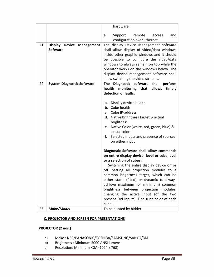
3.0 The item qualifies for Nil duty / Deemed Export benefits. For Deemed Export benefits, please refer
Addendum to the General terms and conditions for Global tender. 4.0 Please note that all tender forms and supporting documents are to be submitted through OIL’s e-
Procurement site only except following documents which are to be submitted manually in sealed envelope super scribed with tender no. and due date to The Head Materials, Materials Department, Oil India Limited, Duliajan- 786602, Assam on or before the Bid Closing Date and Time mentioned in the Tender. a) Original Bid Security. b) Details Catalogue and any other document which have been specified to be submitted in
original. 5.0 In case of SINGLE STAGE-TWO BID SYSTEM, bidders shall prepare the “Techno-Commercial
Unpriced Bid” and “Priced Bid” separately and shall upload through electronic form in the OIL’s e-Tender portal within the Bid Closing Date and Time stipulated in the e-Tender. The “Techno-Commercial Unpriced Bid” shall contain all techno-commercial details except the prices which shall be kept blank and to be uploaded in the c-Folder link (collaboration link) under “Techno-Commercial Bid” Tab. No price details should be uploaded in c-Folder link (collaboration link). Details of prices as per Bid format / Commercial bid to be uploaded as Attachment in the attachment link under “Techno-Commercial Bid”. A screen shot in this regard is given below.
Any offer not complying with above submission procedure will be rejected as per Bid Rejection Criteria mentioned in the tender.
Contd..p/3
SDG6181P13/09
On change Mode- The following screen will appear. Bidders are advised to Upload “Techno-Commercial Unpriced Bid” and “Priced Bid” in the places as indicated below:
Note : * The “Techno-Commercial Unpriced Bid” shall contain all techno-commercial details except the prices. ** The “Price bid” must contain the price schedule and the bidder’s commercial terms and conditions. Contd..p/4
Area for uploading Priced Bid**
Area for uploading Techno-Commercial Unpriced Bid*
Bid on Change Mode
Go to this Tab for Uploading “Techno-commercial Unpriced Bid” as well as “Priced Bid” files.
SDG6181P13/09
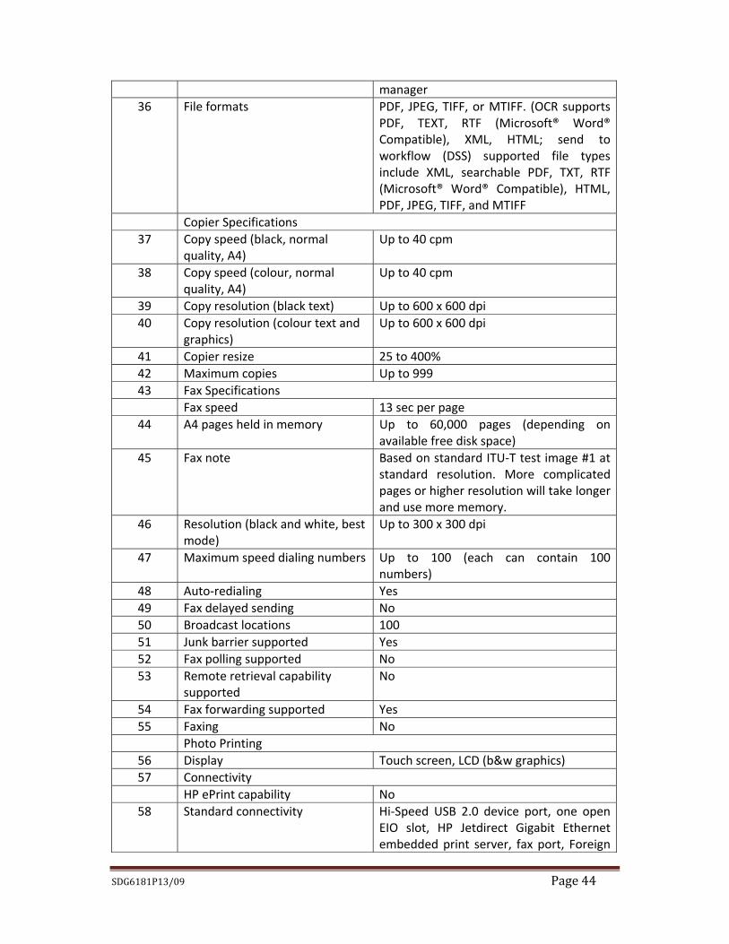
Page..4 6.0 Bidders are requested to examine all instructions, forms, terms and specifications in the bid. Failure
to furnish all information required as per the bid or submission of offers not substantially responsive to the bid in every respect will be at the bidders risk and may result in the rejection of its offer without seeking any clarifications.
7.0 Tax & Duties:
(i) All taxes, stamp duties and other levies imposed outside India shall be the responsibility of the Bidder/Seller and charges thereof shall be included in the offered rates.
(ii) All Taxes & levies imposed in India, for the services including installation & commissioning, training etc. shall be to the Bidder/Seller's account.
(iii) Income Tax on the value of the Services rendered by the Bidder /Seller in connection with installation, commissioning, training etc. shall be deducted at source from the invoices at the appropriate rate under the I.T. Act & Rules from time to time.
8.0 To ascertain the substantial responsiveness of the bid OIL reserves the right to ask the bidder for
clarification in respect of clauses covered under BRC also and such clarifications fulfilling the BRC clauses in toto must be received on or before the deadline given by the company, failing which the offer will be summarily rejected.
9.0 The items covered by this enquiry shall be used by Oil India Limited in the PEL/ML areas which are
issued/renewed after 01/04/99 and hence Nil Customs Duty during import will be applicable. Indigenous bidder shall be eligible for Deemed Export Benefit against this purchase. Details of Deemed Export are furnished vide Addendum to MM/GLOBAL/E-01/2005 attached.
10.0 Other terms and conditions of the tender shall be as per “General Terms & Conditions” for e-
Procurement as per Booklet No. MM/GLOBAL/E-01/2005 for E-procurement (ICB Tenders). However, if any of the Clauses of the Bid Rejection Criteria (BRC) / Bid Evaluation Criteria (BEC) mentioned here contradict the Clauses in the “General Terms & Conditions” for e-Procurement as per Booklet No. MM/GLOBAL/E-01/2005 for E-procurement (ICB Tenders) of the tender and/or elsewhere, those mentioned in this BEC / BRC shall prevail.
11.0 The Integrity Pact is applicable against this tender. OIL shall be entering into an Integrity Pact with
the bidders as per format enclosed vide Annexure XII of the tender document. This Integrity Pact proforma has been duly signed digitally by OIL’s competent signatory. The proforma has to be returned by the bidder (along with the technical bid) duly signed (digitally) by the same signatory who signed the bid, i.e., who is duly authorized to sign the bid. Any bid not accompanied by Integrity Pact Proforma duly signed (digitally) by the bidder shall be rejected straightway. Uploading the Integrity Pact with digital signature will be construed that all pages of the Integrity Pact has been signed by the bidder’s authorized signatory who sign the Bid.
OIL’s Independent External Monitors at present are as under: (I) SHRI N. GOPALASWAMI,I.A.S ( Retd) ,
Former Chief Election Commissioner of India E-mail Id: [email protected]
SECTION – 1 TECHNICAL SPECIFICATIONS AND TERMS OF REFERENCE
1.1 Preamble
Oil India Limited (OIL), a Government of India enterprise, is primarily engaged in exploration, production and transportation of crude oil and natural gas. It has also participating interest in downstream sector of the industry. In line with the long‐term objectives of company and with increasing work volume for Seismic Data Processing, OIL desires to increase the computing power of Seismic Data Processing centre, Duliajan, ASSAM by procuring and installing state of art High Performance Computing Centre (HPCC) including both industry standard latest processing suites & Linux based cluster systems with other peripherals to carry out Time and Depth Domain processing of 2D, 3D, 4D, Multi‐component & VSP dataset.
The HPC Centre will be set‐up through a turn‐key contract with single point
responsibility on the G&G Bidder. This will include amongst others, supply of all necessary Hardware, Application Software, Operating Software, High end Workstations with other Peripherals, design of the HPC Centre, its infra‐structure including internal fittings, lay‐out, light system, acoustics of the Centre, furnishing (soft and hard) air conditioning, UPS etc, installation & commissioning of hardware, installation and configuration of application software, maintenance and training on the system and application software.
The HPC Seismic Data Processing Centre will serve mainly to carry out production
and specialized processing and analysis of seismic data from different spheres of the Company. The Center will also serve to carry out detailed analysis of seismic and well data for reservoir characterization studies. The proposed High Performance Computing Seismic Data Processing Centre is required to meet the following objectives:
Improve productivity & efficiency in Seismic Data Processing. Enable high performance data intensive computations. Tackle complex algorithmic & production‐oriented challenges. Eliminate single point of failure throughout the HPC landscape. Eliminate Performance bottlenecks throughout the HPC landscape. Offer Highly Reliable & High‐performance Scalable Storage Solution. High availability access to data and Application software. Lower risk and project cycle time. Enable data access for visualization from OIL’s remote centres. Enable efficient Interpretive Seismic processing & data analysis. Efficient Imaging of Complex Geology, Seismic modeling & Inversion. Enable efficient Qualitative and quantitative reservoir characterization. Enable efficient data visualization of Seismic datasets. Cater for presentation and discussion facility.
SDG6181P13/09 Page 2
1.2 Brief Description of Scope of work for setting‐up of HPC Seismic Data Processing Center
Apart from supply of necessary hardware, application software, design, fabrication
and setting‐up of the HPC Center, the scope of work necessarily includes connectivity of the HPC Center with the existing resources of the Company at Duliajan. The HPC Seismic Data Processing Centre design and setup must cater effective workspace for simultaneous working of 22 Geophysicists engaged in Seismic Data Processing and Geophysical Data Analysis.
A brief of the key elements, basic building blocks and item‐wise requirement of the
proposed High Performance Computing Seismic Data Processing Center is enumerated as below:
1.2.1 Hardware The Supplier/bidder will offer state‐of the art hardware solution which meets the
technical specifications as stipulated in the bid document. However, bidder is free to propose enhanced specifications with proper justifications and details. OIL, at its sole discretion, may accept such offers in case they are found to be suitable to the specified requirement. The bidder must ensure that the entire HPC landscape is devoid of any single point of failure.
The successful bidder shall undertake installation, integration and commissioning of
all the items supplied as per the terms and conditions stipulated in the bid document. The bidder must provide all the accessories and peripherals viz. cables, cords, connectors, fittings, fixtures etc. required for successful installation and commissioning of the new setup even if the same are not explicitly spelt out in the bid document. These products must confirm to reputed brand and comply with Bureau of Indian Standards (BIS). The bidder must also ensure connection with the existing hardware/network available at OIL.
The entire solution would include setting up a fault‐tolerant infrastructure including
HPC landscape, Servers, Storage, Automated Backup Library, Networks, and Workstations etc. in line with the specifications set forth in this tender. The bidder will also supply and install the entire software stack including Operating System, Application Software, Management Software, Libraries, Compilers, Cluster & System monitoring and management tool and any other software tool required to complete the end‐to‐end solution. The entire solution must be designed for redundancy so that there is no single point of failure. The tentative schematic diagram of the proposed HPC Seismic Data Processing Centre is illustrated in Fig.1
SDG6181P13/09 Page 3
Fig. 1 The proposed High Performance computing Seismic Data Processing Centre should be adequately planned for high availability of equipments/services as required and stipulated
SDG6181P13/09 Page 4
in the bid document including operational and maintenance support to maintain an uptime of 99.98% on a quarterly basis. While it is mandatory for the Bidder to meet these minimum requirements, if the Bidder estimates that a particular requirement would need a higher category of equipment, the Bidder should provision for the same in his bid. The Bidder should however provide basis for arriving at the solution being proposed as part of his bid and its overall efficacy in providing an end to end solutions. However, the sole discretion of accepting such estimates and solution will lie with Oil India Limited. The detailed technical specifications of the hardware solutions are given in SECTION‐2. The key elements/ landscape of the Hardware required for setting up the High Performance Computing Seismic Data Processing Centre are as tabulated below:
Slno Item Description 1 HPC Cluster &
Server Landscape
i) Linux Cluster ii) Intel Xeon 64‐bit 6‐Core X5670 Dual CPU iii) Total Nos. of cores : 840(70 Nodes@12 core) iv) Master Nodes : 2 Nos. in HA mode v) Compute Nodes: 68 Nos. vi) Database Server – 3 Nos. vii) Application Server – 3 Nos. viii) High End Data Analysis Server – 1 No. ix) System Imager Server – 1 No.
2 Storage Parallel File System Based Storage with a useable capacity of 200 TB.
i) Blade enclosures for Blade servers. ii) Racks for other servers. iii) Appropriate blade enclosures/ racks for other equipment.
9 UPS & Batteries i) UPS & Batteries 10 Precision AC i) Precision AC for the infrastructure.
SDG6181P13/09 Page 5
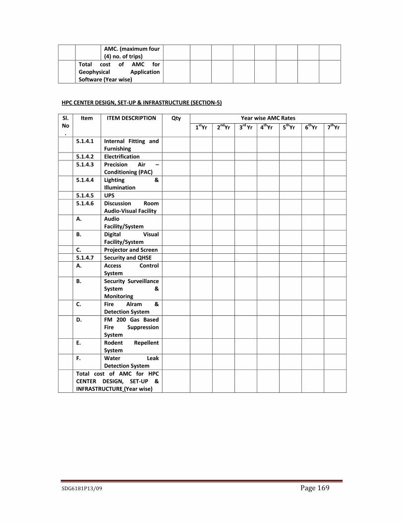
11 Security & QHSE A. Access Control System
i) Smart Card Access System at the Entrance. ii) Time & Attendance Stamp for all Users. iii) Smart Card + Alpha Numeric Code + Biometric fingerprint
technology for entrance into main Server Room. iv) Biometric Door Lock
B. Security Surveillance & Monitoring
i) State of the art Security Surveillance camera for HPC center as detailed in Tender Document.
C. Fire Alarm & Detection System
i) State of the art Fire Alarm & Detection system for HPC center as detailed in the tender document.
D. FM200 GAS Based Fire Suppression system
i) State of the art Gas based Fire suppression system for HPC center as detailed in the tender document.
E. Rodent Repellent System
i) State of the art Rodent Repellent System as detailed in the tender document.
F. Water Leak Detection System
i) State of the art Water Leak Detection system for HPC center as detailed in the tender document.
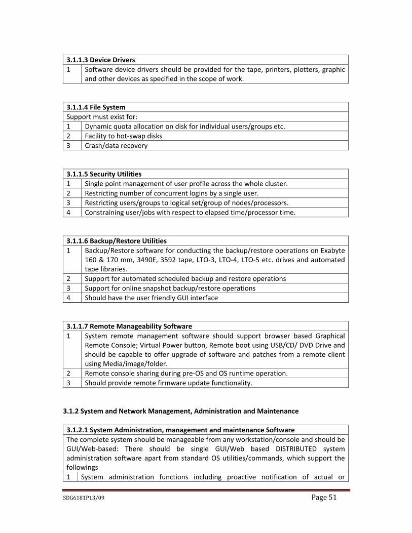
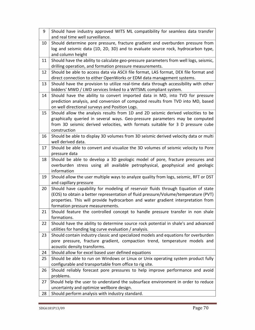
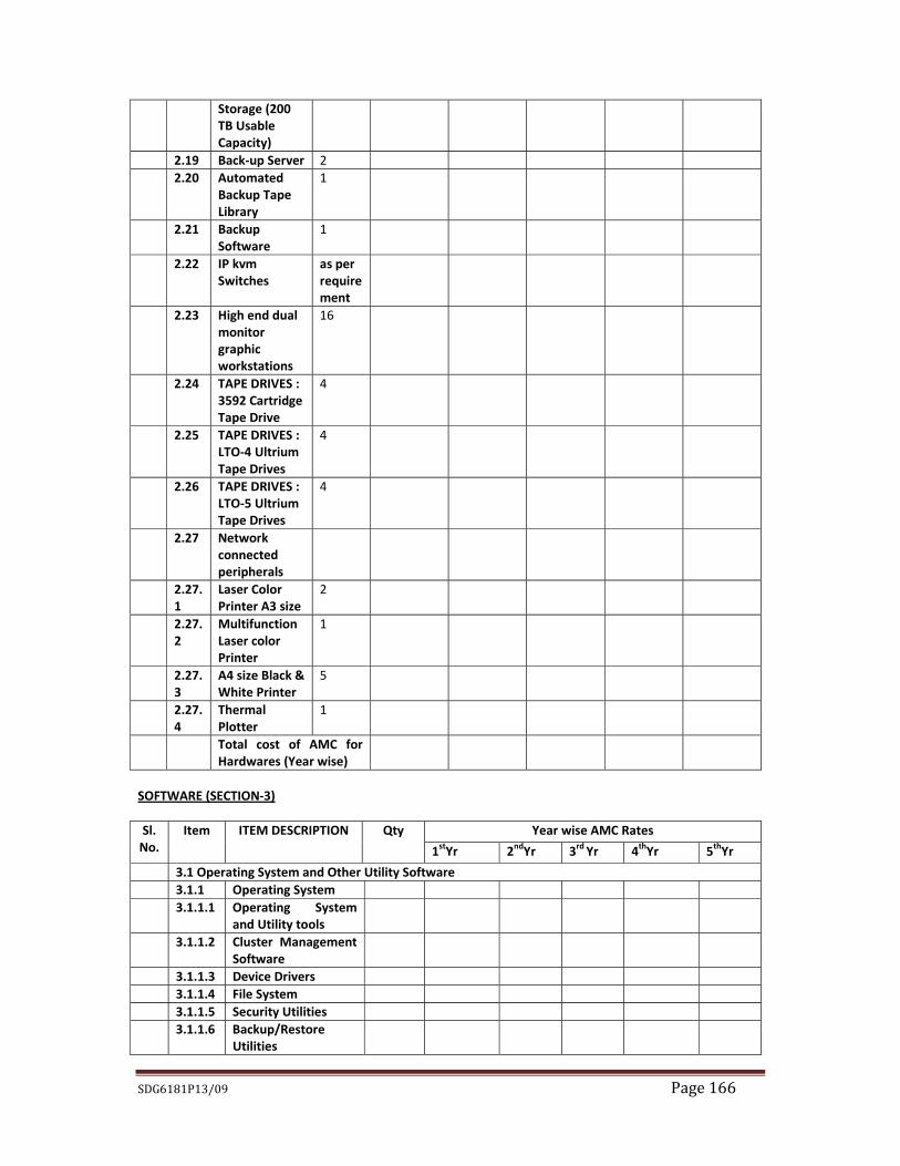
1.2.2 Operating System, Application Software, & Utility Software All cluster and storage solution and other peripherals related software (including its own operating system and software related to Cluster file system, administration & management) like Link software, Backup software, Drivers etc. including Third Party software if any, must be provided on suitable optical media with necessary and adequate number of permanent licenses and enabled at the time of installation & commissioning of the software. All the upgrades of the OS and Cluster, storage system & peripherals related software among others that form a part and parcel of this end to end total solution must be provided to OIL and installed/implemented as and when released by respective parties and it must be supplied along with media free of cost during the warranty and AMC period. Application Software, operating software & all utility software solutions of the HPC centre can broadly be presented as follows:
a) OS for all the systems mentioned in scope of work; b) Application software for complete solution of seismic data processing
centre; c) Cluster Management Tools and Software. d) System Monitoring and Management Software e) Other utility software required for the tape backup, archival, storage etc.
for smooth functioning of HPC Centre.
SDG6181P13/09 Page 6
f) Any other Software/ Middleware tools that may be required for an efficient solution of the proposed HPC set‐up/ landscape.
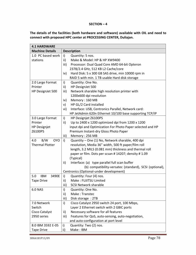
The detailed specification of the software solutions is given in SECTION‐3. 1.2.3 Existing Geophysical data processing facilities with OIL The new HPC setup needs to be connected/integrated to existing workstations and other
peripheral devices viz. plotters, Printers, Tape Drives etc.. The bidder has to ensure seamless integration of the existing devices/peripherals with the new setup in all aspects and enable them at the time of installation and commissioning. The existing processing/reservoir characterization software suites are installed on SGI origin 3900 Server in IRIX environment as well as on recently procured HP workstation in Linux Platform. Provision must be in place for migrating the respective applications to the proposed latest Linux platform. The details of existing infrastructure/resources & application software suites available with the processing facility at OIL are detailed in SECTION ‐ 4.
1.2.4 HPC Center ‐ Room Design and Infra‐structure requirements
1.2.4.1 HPC Center: Design & Infrastructure The Company will provide space (dimensions provided as Enclosure‐I, SECTION 5) for the proposed HPCC. The work will include the following:
a) Detailed design of the HPC Center (Server Room, Processing Room & Discussion Room)
b) Furniture and Interior furnishing of HPC Center c) Precision air‐conditioning d) Electrification and Conditioning of input power. e) Power back‐up through on‐line UPS. f) Lighting and Acoustics. g) Access Control, Security Surveillance & Monitoring h) Hazard Mitigation/ Alarm Devices
The detailed specifications of the room design of the HPC Center and its infra‐structure requirements are given in SECTION ‐ 5. 1.2.4.2 Technical Discussion room with Audio‐Visual Facility.
The Discussion Room broadly covers the following: a) Discussion room. b) Display system for presentations.
The detailed specifications of the display system are given in SECTION – 5. 1.2.5 Installation & Commissioning
SDG6181P13/09 Page 7
1.2.5.1 HPCC design, setup & Infrastructure 1.2.5.2 Hardware, OS & other peripherals 1.2.5.3 Geophysical Application Software
The details of Installation & Commissioning are provided in SECTION – 6. 1.2.6 Warranty, Training, Annual Maintenance Contract of complete HPC system on
Turnkey basis etc. The details of Warranty, Training, AMC are provided in SECTION – 7. 1.2.7 Other terms and conditions Details of the other terms and conditions are given in, SECTION – 8. 1.2.8 Check‐list of all items The list of the checklist is provided in SECTION – 9. 1.2.9 Bid Rejection Criteria / Bid Evaluation Criteria (BRC / BEC) The detailed BRC / BEC are given in SECTION –10. 1.2.10 Price Schedule Given in SECTION – 11. 1.2.11 Commercial Check‐list Given in SECTION – 12.
SDG6181P13/09 Page 8
SECTION – 2
Technical Specification for High Performance Processing Centre
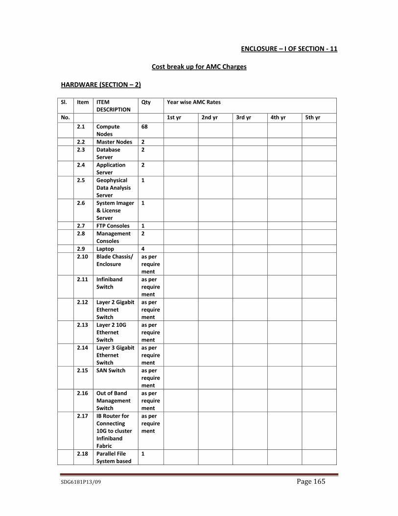
HARDWARE Introduction : OIL intends to procure High Performance Cluster systems with peripherals, configured under Red HAT Enterprise Linux on turnkey basis to process and analyze seismic data using industry standard application software suites as stipulated in the bid document. The offered hardware infrastructure conforming to the technical specification as detailed below must be seamlessly integrated with the Application Software for optimal performance. Over and above the hardware items mentioned in the tender document, any component which is not explicitly mentioned but is critical for installation, commissioning, effective utilization & optimal performance of the proposed HPC setup must form a part and parcel of the solution offered by the bidder. Bidders must not propose solutions involving products that have reached or are near end of life. OEM certificate to the effect is to be submitted along with the bid. OEM should also certify for the availability of spares for next five years. The bidder must quote for all the items mentioned in the tender. The Make of servers and workstations quoted by the bidder for the solution must be limited to the OEMs namely M/s IBM, HP & DELL. Summary of the Requirements:
Sl. No. Description Quantity (Nos.) 2.1 Compute Nodes 68 2.2 Master Nodes 2 2.3 Database Server 3 2.4 Application Server 3 2.5 Geophysical Data Analysis Server 1 2.6 System Imager & License Server 1 2.7 FTP Console 1 2.8 Management Consoles 2 2.9 Laptop 4
2.10 Blade Chassis/ Enclosure As per requirement 2.11 Infiniband Switch As per requirement 2.12 Layer 2 Gigabit Ethernet Switch As per requirement 2.13 Layer 2 10G Ethernet Switch As per requirement 2.14 Layer 3 Gigabit Ethernet Switch As per requirement 2.15 SAN Switch As per requirement 2.16 Out of Band Management Switch As per requirement 2.17 IB Router for Connecting 10G to Cluster
Infiniband Fabric As per requirement
SDG6181P13/09 Page 9
2.18 Parallel File System based Storage (200 TB Useable Capacity)
1
2.19 Back‐up Server 2 2.20 Automated Backup Tape Library 1 2.21 Backup Software 1 2.22 IP kvm Switches As per requirement 2.23 High end dual monitor graphic workstations 16 2.24 TAPE DRIVES : 3592 cartridge Tape Drives 4 2.25 TAPE DRIVES : LTO‐4 Ultrium Tape Drives 4 2.26 TAPE DRIVES : LTO‐5 Ultrium Tape Drives 4 2.27 Network connected peripherals
2.27.1 Laser Color printer 2.27.2 Multifunction Laser Color printer 2.27.3 A4 size Black & White Printer 2.27.4 Thermal Plotter
2 1 5 1
2.28 Consumables As detailed in appropriate sections
1 System PC Cluster based 2 No of Compute Nodes 68 3 No of CPU per Node Two (Dual) 4 No of Processor Cores per CPU Six (6) 5 Total No. of Processor Cores 816 cores 6 Processor Intel Xeon Westmere X5670; 2.93 GHz or higher
[64 bit x86_64 processor] 7 Chipset Intel 5520 8 Processor Front Side Bus Intel QPI (Quick Path Interface) 6.4 GT/s or
better 9 Processor L3 Cache per node Minimum 12 MB or highest available
10 RAM/Memory per node 96 GB DDR3 ECC (1333 MHz or better) 11 Hard Disk drive per node 2X600 GB, 15000 RPM, 6Gb/s SAS Hot
Pluggable Internal HDD 12 I/O Expansion slots Minimum 2 nos empty 64 bit PCIe (PCI‐Express)
Slots 13 NIC Ports Minimum 2 X 10/100/1000Mbps Ethernet Ports
on‐board with Wake‐on‐LAN feature, RJ‐45 Connector
14 Built In I/O Minimum 2 serial, Minimum 4 USB 2.0 ports 15 HCA (Host Channel Adapter) 100% non‐blocking 4 X QDR Infiniband for Inter‐
Node Communication 16 Remote Management Port RJ45 based Remote Management Port with
IPMI 2.0 Support. It should provide the
SDG6181P13/09 Page 10
Integrated Lights‐Out Manager (ILOM) or equivalent, Service processor with GUI, SNMP based Manager etc.
17 Operating system 64 bit Red Hat Enterprise Linux 18 OS Compatibility &
Certification Red Hat Enterprise Linux, Microsoft Windows Server & Suse Linux
19 Optical Drive 16XDVD+RW Drive 20 Redundant modules Power supply, cooling fans 21 Hot‐swap components Power supplies, fan modules, hard disk drives 22 Diagnostics Identification of Failed Components through
LEDs/LCDs 23 Remote Manageability Remote management card, Server management
software, Complete hardware based remote administration from a standard web browser with event logging, detailed server status. Logs, alert forwarding and virtual control for remote boot and administration.
24 Cluster Management Management software should be a browser based interface from the OEM bidder capable of doing asset tracking, change management and pre‐failure alert
25 Compilers C, C++, Fortran compilers & Complete Java IDE (Integrated Development Environment) with unlimited user licence
26 Middleware Complete Middleware suite (Web, proxy/cache, Java application, Portal, Messaging, Calendar, Directory servers & Grid Engine)
27 Supported graphics Integrated /supplied graphics port 28 Form Factor Blade Servers with necessary Chassis Enclosure
configured with N+N redundant hot plug power supplies, redundant hot plug cooling fans, redundant management controllers, Ethernet Chassis Switch, integrated KVM Switch, Optical Drive, Cable Management Arm.
29 Mounting Should plug securely and easily with the Blade Enclosure backplane for both data and power transmission
30 Make HP/ IBM/ DELL (Should be of the same Make across the entire HPC Landscape)
31 Model To be quoted by bidder 2.2 Master Node: 2 Nos configured in High Available Mode Slno Parameter Specification 1 No of Nodes 2 2 Configuration Must be configured in High Availability mode
SDG6181P13/09 Page 11
Servers shall be configured in Active Passive Mode through clustering tools.
3 No of CPU per Node Two (Dual) 4 No of Processor Cores per CPU Six (6) 5 Individual processor Intel Xeon X5670 or better Westmere processor;
2.93 GHz or higher [64 bit x86_64 processor] 6 Processor Front Side Bus Intel QPI (Quick Path Interface) 6.4 GT/s or
better 7 Processor L3 Cache Minimum 12 MB or highest available 8 RAM/Memory per node 96 GB DDR3 ECC (1333 MHz or better) 9 Hard Disk drive 5 x 600 GB, 15000 RPM, SAS Hot Pluggable
Internal HDDs; HDDs must be configured with Hardware RAID Controller in RAID 5; Server should be scalable to min 8 HDDs.
11 I/O Expansion slots 2 Nos. empty 64 bit PCIe (PCI‐Express) Slots 12 NIC Ports Minimum 4 X 1 G Ethernet; 2 X 10 G Ethernet
with RJ45 ports. Other ports as per the requirement of HPC should be supplied.
13 Built In I/O Minimum 2 serial, Minimum 4 USB 2.0 ports 14 HBA (Host Bus Adapter) Dual port 8Gb/s FC HBA Card 15 Remote Management Port RJ 45 based Remote Management Port with
IPMI 2.0 Support. It should provide the Integrated Lights‐Out Manager (ILOM) or equivalent, Service processor with GUI, SNMP based Manager etc.
16 Operating system 64 bit Red Hat Enterprise Linux 17 OS Compatibility &
Certification RHEL, Suse Linux, Microsoft Windows Server
18 Optical Drive 16XDVD+RW Drive 19 Redundant modules Power supply, cooling fans, Hard disk drives 20 Hot‐swap components Power supplies, fan modules, hard disk drives 21 Features X‐Windows software for enabling GUI based
applications must be provided 22 Diagnostics Identification of Failed Components through
LEDs/LCDs 23 Remote Manageability Remote management card, Server management
software, Complete hardware based remote administration from a standard web browser with event logging, detailed server status. Logs, alert forwarding and virtual control for remote boot and administration
24 Cluster Management Management software should be a browser based interface from the OEM bidder capable of
SDG6181P13/09 Page 12
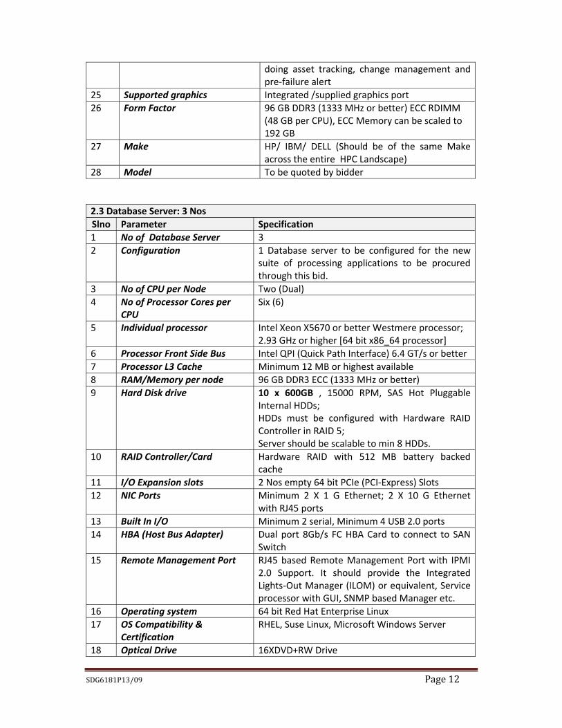
doing asset tracking, change management and pre‐failure alert
25 Supported graphics Integrated /supplied graphics port 26 Form Factor 96 GB DDR3 (1333 MHz or better) ECC RDIMM
(48 GB per CPU), ECC Memory can be scaled to 192 GB
27 Make HP/ IBM/ DELL (Should be of the same Make across the entire HPC Landscape)
28 Model To be quoted by bidder 2.3 Database Server: 3 Nos Slno Parameter Specification 1 No of Database Server 3 2 Configuration 1 Database server to be configured for the new
suite of processing applications to be procured through this bid.
3 No of CPU per Node Two (Dual) 4 No of Processor Cores per
CPU Six (6)
5 Individual processor Intel Xeon X5670 or better Westmere processor; 2.93 GHz or higher [64 bit x86_64 processor]
6 Processor Front Side Bus Intel QPI (Quick Path Interface) 6.4 GT/s or better 7 Processor L3 Cache Minimum 12 MB or highest available 8 RAM/Memory per node 96 GB DDR3 ECC (1333 MHz or better) 9 Hard Disk drive 10 x 600GB , 15000 RPM, SAS Hot Pluggable
Internal HDDs; HDDs must be configured with Hardware RAID Controller in RAID 5; Server should be scalable to min 8 HDDs.
11 I/O Expansion slots 2 Nos empty 64 bit PCIe (PCI‐Express) Slots 12 NIC Ports Minimum 2 X 1 G Ethernet; 2 X 10 G Ethernet
with RJ45 ports 13 Built In I/O Minimum 2 serial, Minimum 4 USB 2.0 ports 14 HBA (Host Bus Adapter) Dual port 8Gb/s FC HBA Card to connect to SAN
Switch 15 Remote Management Port RJ45 based Remote Management Port with IPMI
2.0 Support. It should provide the Integrated Lights‐Out Manager (ILOM) or equivalent, Service processor with GUI, SNMP based Manager etc.
16 Operating system 64 bit Red Hat Enterprise Linux 17 OS Compatibility &
Certification RHEL, Suse Linux, Microsoft Windows Server
18 Optical Drive 16XDVD+RW Drive
SDG6181P13/09 Page 13
19 Redundant modules Power supply, cooling fans, Hard disk drives 20 Hot‐swap components Power supplies, fan modules, hard disk drives 21 Features X‐Windows software for enabling GUI based
applications must be provided 22 Diagnostics Identification of Failed Components through
LEDs/LCDs 23 Remote Manageability Remote management card, Server management
software, Complete hardware based remote administration from a standard web browser with event logging, detailed server status. Logs, alert forwarding and virtual control for remote boot and administration
24 Supported graphics Integrated /supplied graphics port 25 Form Factor 1U/ 2U rack mountable with Rail kit 26 Make HP/ IBM/ DELL (Should be of the same Make
across the entire HPC Landscape) 27 Model To be quoted by bidder
2.4 Application Server: 3 Nos Slno Parameter Specification 1 No of Application Servers 3 2 Configuration One (1) Application server to be configured for
the new suite of processing applications to be procured through this bid. The other two servers must have all the OS & other utilities installed & configured as for the main application server. These must have all the provisions required for their usage for other set of application that OIL may install in immediate near future.
3 No of CPU per Node Two (Dual) 4 No of Processor Cores per
CPU Six (6)
5 Individual processor Intel Xeon X5670 or better Westmere processor; 2.93 GHz or higher [64 bit x86_64 processor]
6 Processor Front Side Bus Intel QPI (Quick Path Interface) 6.4 GT/s or better 7 Processor L3 Cache Minimum 12 MB or highest available 8 RAM/Memory per node 96 GB DDR3 ECC (1333 MHz or better) 9 Hard Disk drive 10 X 600 GB, 15000 RPM, SAS Hot Pluggable
Internal HDDs; HDDs must be configured with Hardware RAID Controller in RAID 5;
11 I/O Expansion slots 2Nos empty 64 bit PCIe (PCI‐Express) Slots 12 NIC Ports Minimum 2 X 1 G Ethernet; 2 X 10 G Ethernet
SDG6181P13/09 Page 14
with RJ45 ports 13 Built In I/O Minimum 2 serial, Minimum 4 USB 2.0 ports 14 HBA (Host Bus Adapter) Dual port 8Gb/s FC HBA Card to connect to SAN
Switch 15 Remote Management Port RJ45 based Remote Management Port with IPMI
2.0 Support. It should provide the Integrated Lights‐Out Manager (ILOM) or equivalent, Service processor with GUI, SNMP based Manager etc.
16 Operating system 64 bit Red Hat Enterprise Linux 17 OS Compatibility &
Certification RHEL, Suse Linux, Microsoft Windows Server
18 Optical Drive 16XDVD+RW Drive 19 Redundant modules Power supply, cooling fans, Hard disk drives 20 Hot‐swap components Power supplies, fan modules, hard disk drives 21 Features X‐Windows software for enabling GUI based
applications must be provided 22 Diagnostics Identification of Failed Components through
LEDs/LCDs 23 Remote Manageability Remote management card, Server management
software, Complete hardware based remote administration from a standard web browser with event logging, detailed server status. Logs, alert forwarding and virtual control for remote boot and administration
24 Supported graphics Integrated /supplied graphics port 25 Form Factor 1U/ 2U rack mountable with Rail kit 26 Make HP/ IBM/ DELL (Should be of the same Make
across the entire HPC Landscape) 27 Model To be quoted by bidder
2.5 Geophysical Data Analysis Server: 1 No Slno Parameter Specification 1 No of CPU per Node Four (4) 2 No of Processor Cores per
CPU Eight (8)
3 Processor Intel Xeon 7500 8‐Core Series (1.8 GHz or higher) 4 Processor Front Side Bus Intel QPI (Quick Path Interface) 5.8 GT/s or better 5 Processor L3 Cache Minimum 18 MB 6 RAM/Memory per node 128 GB DDR3 ECC (1066 MHz or better) 7 Hard Disk drive 6X600GB, 15000 RPM, SAS Hot Pluggable Internal
HDDs; HDDs must be configured with Hardware RAID Controller in RAID 5;
8 RAID Controller/Card Hardware RAID with 512 MB battery backed cache 9 I/O Expansion slots 3 Nos empty 64 bit PCIe Gen2 Slots 10 NIC Ports Minimum 2 X 1 G Ethernet; 2 X 10 G Ethernet with
SDG6181P13/09 Page 15
RJ45 ports 11 HBA (Host Bus Adapter) Dual port 8Gb/s FC HBA Card to connect to SAN
Switch 12 Remote Management Port RJ45 based Remote Management Port with IPMI
2.0 Support. It should provide the Integrated Lights‐Out Manager (ILOM) or equivalent, Service processor with GUI, SNMP based Manager etc.
13 Operating system 64 bit Red Hat Enterprise Linux 14 OS Compatibility &
Certification RHEL, Suse Linux, Microsoft Windows Server
15 Optical Drive 16XDVD+RW Drive 16 Redundant modules Power supply, cooling fans, Hard disk drives 17 Hot‐swap components Power supplies, fan modules, hard disk drives 18 Features X‐Windows software for enabling GUI based
applications must be provided 19 Diagnostics Identification of Failed Components through
LEDs/LCDs 20 Remote Manageability Remote management card, Server management
software, Complete hardware based remote administration from a standard web browser with event logging, detailed server status. Logs, alert forwarding and virtual control for remote boot and administration
21 Management Management software should be a browser based interface from the OEM bidder capable of doing asset tracking, change management and pre‐failure alert
22 Supported graphics Integrated/ supplied graphics port 23 Power Supply Hot‐plug redundant 230 V AC Energy Smart PSU 24 Form Factor Rack mountable with necessary rail kit 25 Make HP/ IBM/ DELL (Should be of the same Make as
that of the HPC Solution) 26 Model To be quoted by bidder NOTE: The Geophysical data analysis server needs to be connected to the five nos. of existing workstations (HP xw9400) and 20TB of SAN storage (HP StorageWorks HSV300).
2.6 System Imager & License Server: 1 No Slno Parameter Specification 1 No of Application Servers 1 2 No of CPU per Node Two (Dual) 3 No of Processor Cores per
CPU Six (6)
4 Individual processor Intel Xeon X5670 or better Westmere processor; 2.93 GHz or higher [64 bit x86_64 processor]
5 Processor Front Side Bus Intel QPI (Quick Path Interface) 6.4 GT/s or better
SDG6181P13/09 Page 16
6 Processor L3 Cache54 Minimum 12 MB or highest available 7 RAM/Memory per node 96 GB DDR3 ECC (1333 MHz or better) 8 Hard Disk drive 5 x 600 GB, 15000 RPM, SAS Hot Pluggable
Internal HDDs; HDDs must be configured with Hardware RAID Controller in RAID 5; Server should be scalable to min 8 HDDs.
10 I/O Expansion slots 2 Nos empty 64 bit PCIe (PCI‐Express) Slots 11 NIC Ports Minimum 2 X 1 G Ethernet; 2 X 10 G Ethernet
with RJ45 ports 12 Built In I/O Minimum 2 serial, Minimum 4 USB 2.0 ports 13 HBA (Host Bus Adapter) Dual port 8Gb/s FC HBA Card to connect to SAN
Switch 14 Remote Management Port RJ45 based Remote Management Port with IPMI
2.0 Support. It should provide the Integrated Lights‐Out Manager (ILOM) or equivalent, Service processor with GUI, SNMP based Manager etc.
15 Operating system 64 bit Red Hat Enterprise Linux 16 OS Compatibility &
Certification RHEL, Suse Linux, Microsoft Windows Server
17 Optical Drive 16XDVD+RW Drive 18 Redundant modules Power supply, cooling fans, Hard disk drives 19 Hot‐swap components Power supplies, fan modules, hard disk drives 20 Features X‐Windows software for enabling GUI based
applications must be provided 21 Diagnostics Identification of Failed Components through
LEDs/LCDs 22 Remote Manageability Remote management card, Server management
software, Complete hardware based remote administration from a standard web browser with event logging, detailed server status. Logs, alert forwarding and virtual control for remote boot and administration
23 Supported graphics Integrated /supplied graphics port 24 Form Factor 1U/ 2U rack mountable with Rail kit 25 Make HP/ IBM/ DELL (Should be of the same Make as
that of the HPC Solution) 26 Model To be quoted by bidder
2.7 FTP Console : 1 Nos. Slno Parameter Specification 1 No of CPU One(1) 2 No of Processor Four (4) or higher
SDG6181P13/09 Page 17
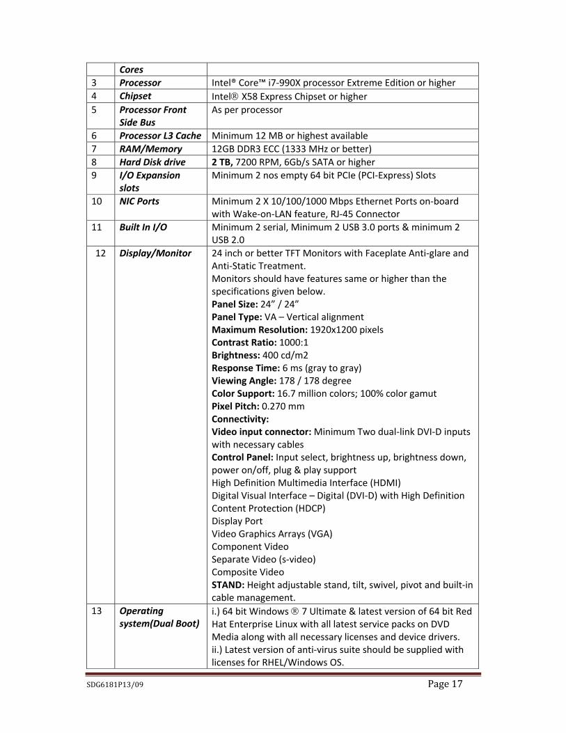
Cores 3 Processor Intel® Core™ i7‐990X processor Extreme Edition or higher 4 Chipset Intel X58 Express Chipset or higher 5 Processor Front
Side Bus As per processor
6 Processor L3 Cache Minimum 12 MB or highest available 7 RAM/Memory 12GB DDR3 ECC (1333 MHz or better) 8 Hard Disk drive 2 TB, 7200 RPM, 6Gb/s SATA or higher 9 I/O Expansion
slots Minimum 2 nos empty 64 bit PCIe (PCI‐Express) Slots
10 NIC Ports Minimum 2 X 10/100/1000 Mbps Ethernet Ports on‐board with Wake‐on‐LAN feature, RJ‐45 Connector
11 Built In I/O Minimum 2 serial, Minimum 2 USB 3.0 ports & minimum 2 USB 2.0
12 Display/Monitor 24 inch or better TFT Monitors with Faceplate Anti‐glare and Anti‐Static Treatment. Monitors should have features same or higher than the specifications given below. Panel Size: 24” / 24” Panel Type: VA – Vertical alignment Maximum Resolution: 1920x1200 pixels Contrast Ratio: 1000:1 Brightness: 400 cd/m2 Response Time: 6 ms (gray to gray) Viewing Angle: 178 / 178 degree Color Support: 16.7 million colors; 100% color gamut Pixel Pitch: 0.270 mm Connectivity: Video input connector: Minimum Two dual‐link DVI‐D inputs with necessary cables Control Panel: Input select, brightness up, brightness down, power on/off, plug & play support High Definition Multimedia Interface (HDMI) Digital Visual Interface – Digital (DVI‐D) with High Definition Content Protection (HDCP) Display Port Video Graphics Arrays (VGA) Component Video Separate Video (s‐video) Composite Video STAND: Height adjustable stand, tilt, swivel, pivot and built‐in cable management.
13 Operating system(Dual Boot)
i.) 64 bit Windows 7 Ultimate & latest version of 64 bit Red Hat Enterprise Linux with all latest service packs on DVD Media along with all necessary licenses and device drivers. ii.) Latest version of anti‐virus suite should be supplied with licenses for RHEL/Windows OS.
SDG6181P13/09 Page 18
14 OS Compatibility & Certification
Red Hat Enterprise Linux, Microsoft Windows Server & SUSE Linux
15 Optical Drive Two Nos. of Blu‐ray Disc Drive (BD/DVD/CD) burner w/double layer BD write
16 Supported graphics
Integrated /supplied graphics port
17 Card reader Card reader must support the following devices
Microdrive Compact Flash Type I/II Multimedia RS‐MMC* Smart Media card Memory Stick Memory Stick Pro Memory Stick Duo* Memory Stick Pro Duo* Secure Digital SD Mini* MS Magic Gate MS Magic Gate Duo MS Pro Magic Gate MS Pro Magic Gate Duo MS Select MS ROM T‐Flash Photo memory card with extremely mini size
18 Form Factor Tower model. 19 Make HP/ IBM/ DELL (Should be of the same Make as that of the
HPC Solution) 20 Model To be quoted by bidder Note: The FTP consoles will be required for data management, FTP transfer etc.
2.8 Management Consoles (through KVM over IP): 2 Nos. Slno Parameter Specification 1 No of Processor One (1) 2 No of Processor
Cores Four (4) or higher
3 Processor Intel® Core™ i7‐990X processor Extreme Edition or higher 4 Chipset Intel X58 Express Chipset or higher 5 Processor Front
Side Bus As per processor
6 Processor L3 Cache Minimum 8 MB or highest available 7 RAM/Memory 12GB(2X4GB/2X2GB) DDR3 SDRAM (1333 MHz or better)
SDG6181P13/09 Page 19
8 Hard Disk drive 2X500 GB, 7200 RPM, 6Gb/s SATA 9 I/O Expansion
slots Minimum 2 nos empty 64 bit PCIe (PCI‐Express) Slots
10 NIC Ports Minimum 2 X 10/100/1000 Mbps Ethernet Ports on‐board with Wake‐on‐LAN feature, RJ‐45 Connector
11 Built In I/O Minimum 2 serial, Minimum 2 USB 3.0 ports & minimum 2 USB 2.0
12 Display/Monitor 24 inch or better TFT Monitors with Faceplate Anti‐glare and Anti‐Static Treatment. Monitors should have features same or higher than the specifications given below. Panel Size: 24” / 24” Panel Type: VA – Vertical alignment Maximum Resolution: 1920x1200 pixels Contrast Ratio: 1000:1 Brightness: 400 cd/m2 Response Time: 6 ms (gray to gray) Viewing Angle: 178 / 178 degree Color Support: 16.7 million colors; 100% color gamut Pixel Pitch: 0.270 mm Connectivity: Video input connector: Minimum Two dual‐link DVI‐D inputs with necessary cables Control Panel: Input select, brightness up, brightness down, power on/off, plug & play support High Definition Multimedia Interface (HDMI) Digital Visual Interface – Digital (DVI‐D) with High Definition Content Protection (HDCP) Display Port Video Graphics Arrays (VGA) Component Video Separate Video (s‐video) Composite Video STAND: Height adjustable stand, tilt, swivel, pivot and built‐in cable management.
13 Operating system i.) 64 bit Windows 7 Ultimate/64 bit Red Hat Enterprise Linux with all latest service packs on DVD Media along with all necessary licenses and device drivers. ii.) Latest version of anti‐virus suite should be supplied with licenses for RHEL/Windows OS.
14 OS Compatibility & Certification
Red Hat Enterprise Linux, Microsoft Windows Server & SUSE Linux
15 Optical Drive Two Nos. of Blu‐ray Disc Drive (BD/DVD/CD) burner w/double layer BD write
16 Redundant modules
Power supply, cooling fans
17 Hot‐swap Power supplies, fan modules, hard disk drives
SDG6181P13/09 Page 20
components 18 Diagnostics Identification of Failed Components through LEDs/LCDs 19 Supported
graphics Integrated /supplied graphics port
20 Card reader Card reader must support the following devices
Microdrive CompactFlash Type I/II Multimedia RS‐MMC* Smart Media card Memory Stick Memory Stick Pro Memory Stick Duo* Memory Stick Pro Duo* Secure Digital SD Mini* MS Magic Gate MS Magic Gate Duo MS Pro Magic Gate MS Pro Magic Gate Duo MS Select MS ROM T‐Flash Photo memory card with extremely mini size
21 Form Factor Tower model. 22 Make HP/ IBM/ DELL (Should be of the same Make as that of the
HPC Solution) 23 Model To be quoted by bidder Note: The management consoles will be connected to the KVM over IP switch for gaining access to servers, clusters, storage & backup infrastructure up to console level.
2.9 Laptop: 4 Nos. Slno Parameter Specification 1 No of Processor One (1) 2 Processor 2nd Generation Intel® Core™ i7 Mobile
Processor Extreme Edition or higher 3 Chipset Intel® QM67 Express Chipset 4 Processor L3 Cache Minimum 8 MB or highest available 5 RAM/Memory 12GB 1333MHz DDR3 SDRAM (3 x 4GB) 6 Hard Disk drive 750 GB hard drive (7200RPM, 6Gb/s SATA) or
higher 7 I/O Expansion slots Minimum 2 nos empty 64 bit PCIe (PCI‐Express)
Slots 8 Ports,slot Mini Display Port (1),
SDG6181P13/09 Page 21
2 total USB 3.0 2 total USB 2.0 (1 / 1 eSATA/powershare combo) Integrated network connector 10/100/1000 LAN (RJ45) HDMI 1.4 AC adapter connector Audio jacks: headphone(2 total) with SPID/F support (1), 1 Mic‐in
9 Display/Screen 17.3” (43.94cm) FHD WLED TL (1920x1080) 10 Operating system Windows® 7 Ultimate 64‐Bit / 64 bit Red Hat
Enterprise Linux 11 OS Compatibility & Certification Red Hat Enterprise Linux,Microsoft Windows® 7
w/double layer BD write 13 Supported graphics 3GB NVIDIA® GeForce® GT 555M 14 Camera 2.0MP HD with single digital mic (H.264) 15 Wi‐Fi Options Integrated
16 Bluetooth Bluetooth® Internal (3.0) mini‐card 17 Card reader SD, SDIO, SDXC, SDHC, MS, MS Pro, MMC,
MSXC, xD 18 Power 9‐cell LI (2.8Ah 90Whr); Up to 5 hours,130W AC
adapter standard; 150W AC adapter with 3GB graphics
19 Make HP/ IBM/ DELL (Should be of the same Make as that of the HPC Solution)
20 Model To be quoted by bidder Note: The Laptop will be required for existing modeling software, technical seminar, presentation, discussion at the conference room as well as for the visualization of geoscientific dataset.
2.10 Blade Chassis/ Enclosure: Qty as per requirement Slno Parameter Specification 1 General
Description Appropriate sized blade enclosure/chassis capable of (a) housing all compute node servers, and (b) of providing common resources for blade servers such as power, system management, cabling, infiniband & Ethernet network management and expansion, external storage, switching and connectivity, and I/O (ports for USB, keyboard, video, mouse, optical drive, etc.). Chassis should provide adequate redundancy features ensuring arrest of any single point of failure.
2 Internal Resource Within chassis connectivity of shared resources may be
SDG6181P13/09 Page 22
Connectivity through a redundant mid‐plane (1+1) or a passive back‐plane.
3 Cluster Primary Interconnect
4XQDR InfiniBand Switch Module with minimum required number of ports (each port supporting up to 40 Gbps) and with necessary cables for populating required number of blade servers; 10% spare ports should be available; InfiniBand Switch specifications should be as per Item no 2.11
4 Cluster Secondary Interconnect
Gigabit LAN Switch Module with minimum required number of ports (each port supporting up to 1 Gbps) and with necessary cables for populating maximum number of blade servers; 10% spare ports should be available; Gigabit LAN Switch specifications should be as per Item no 2.12 ,2.13 & 2.14.
5 Management Modules
Chassis to be equipped and configured with hot‐pluggable management modules; Must be configured in dual‐redundant mode; To provide IP‐based management of the blade servers and other vital components, switching, health monitoring, inventory management, and remote console to each blade.
6 Congestion Control Feature
Hardware based Congestion Control for entire IB interconnects system.
7 KVM over IP Support
Blade chassis should be equipped with support for keyboard, video, and mouse; Console access over IP should be possible.
8 CD/USB Chassis may be equipped with USB port and DVD‐ROM drive accessible from and usable by individual blades inside the chassis.
9 Cooling 100% redundant cooling to be provided inside the chassis; Cooling system should be capable of dissipating, efficiently and without processor throttling; all heat generated by a fully‐populated chassis with highest configuration blade servers running at highest possible power rating.
10 Power Modules N + N redundancy to be provided on hot‐pluggable power supplies powering the chassis, with each power supply unit of the highest capacity available with the bidder; Should be configured in redundant mode.
11 Power Supply Unit 230 V AC, 50 Hz 12 Chassis
Management and Software
i) Chassis should provide support for (a) remote console management, (b) powering on/off individual blades, (c) monitoring of power status, operating system events, temperature, disks, blowers/fans, power modules, and system diagnostics through the chassis management software. Chassis management controller/software (CMC/S) should be from the OEM itself, and software licenses for a fully‐populated blade enclosure should be included in the chassis
SDG6181P13/09 Page 23
price. ii) The CMC/S should provide standard features such as:
(a) role‐based (admin, user, operator, etc.) security that allows effective delegation of management responsibilities by giving systems administrators granular control over which users can perform which management operations on which devices, etc.; (b) proactive notification of actual or impending component failure alerts; (c) automatic event handling that allows notification of failures via e‐mail; (d) performance monitoring and analysis features such as detection and analysis of hardware bottlenecks; (e) user‐friendly GUI/console‐based configuration and deployment of OS and software applications on individual blades.
iii) Desirable features include: (a) comprehensive system
data collection and ability to produce detailed inventory reports for managed devices; (b) proactive identification of out‐of‐date BIOS, drivers, and server management agents; (c) remote update of system software/firmware components; (d) scheduling periodic server configuration snapshots etc.
iv) Should help to proactively identify out‐of‐date BIOS,
drivers & Software and enable remote update of system software/firmware components.
v) Multiple subnets management with dynamic port
allocation, port mirroring, fabric diagnostic and fabric debug tools.
13 Deployment Software
User friendly GUI/ console‐based deployment to set up and install multiple OS and application configurations in individual blade server.
14 System Software Comprehensive web enabled system management tool that monitors the system health, environment, critical action etc, With its own data engine to store status reports, alerts and error notifications, Automatic Server Recovery (ASR) Complete Administration of the node enclosure from a standard web‐browser With event logging, detailed server status, alert forwarding, Remote graphical console, remote power control / shutdown, virtual floppy and CD for remote boot and configuration, virtual text and graphical control, automatic IP configuration via DHCP/DNS/WINS with 128 bit SSL encryption security. The system software should have the capability of managing
SDG6181P13/09 Page 24
the entire blade servers in the Enclosures simultaneously. 15 System Panel LED panel to provide adequate information about power‐
on, location, over‐heating and other system error conditions, etc.
16 Clustering Support
The chassis should support configuration of high‐availability cluster with no single point of failure on components like switches, I/O connectors, power modules, etc.
17 Form Factor As required by the solution 18 Make/Model To be quoted by bidder
2.11 Infiniband Switch: Qty as per requirement including 100% redundancy Slno Parameter Specification 1 Speed Rating 4X QDR. Should be compatible with HCA on master and
compute nodes fully non‐blocking switching/interconnectivity between master and compute node
2 Topology Fat Tree 100% non‐blocking topology 3 Number of ports Required number of ports ensuring redundancy 4 Form Factor Internal to the blade chassis 5 Make (i) Switch – along with the HCAs for Nodes ‐ should be
of the same make (ii) Mellanox/ Voltaire/ Qlogic
6 Bandwidth Full bisectional bandwidth to all ports (ie. all the nodes on one half of the network can communicate with the nodes on the other half at full speed)
2.12 Layer 2 Gigabit Ethernet Switch: Qty as per requirement including 100% redundancy Slno Parameter Specification 1 System Rack mounted 2 Switch Type Layer 2, manageable 3 Interface 1 Gbps per port Ethernet copper
SDG6181P13/09 Page 25
4 Number of Ports per Switch
Minimum 48 wire‐speed non‐blocking ports
5 Uplink Ports 10 g Ethernet 6 USB Port YES 7 Management/Console
port dedicated 10/100/1000
8 Power supply 1:1 Redundant and hot‐swappable 9 Cooling Fans Hot‐swappable field replaceable redundant fans 10 Protocols Should support all standard multi protocols 11 Accessories All patch cords, patch panels, cables etc. for all ports
must be offered. All accessories required to install and configure the entire network as per the enclosed network diagram must be provided by the bidder.
12 Features i) Should support Ethernet Channel protocol, Load Balancing and Fail over. In‐service‐software‐upgrade.
ii) Shall support IEEE 802.1Q
iii) Shall support loopback interface address improving diagnostic capability.
iv) Switch must be Enterprise class and should support
industry standard Security, Convergence and QoS and manageability features.
13 High Availability i) Dual, redundant management ports. ii) Shall support IEEE 802.3ad Link Aggregation Control
Protocol. iii) Shall support server‐to‐switch distributed trunking
allowing a server to connect to two switches with one logical trunk.
iv) Shall support IEEE 802.1s Multiple Spanning Tree
Protocol. v) Shall have capability to dynamically load‐balance
across multiple active redundant links 14 Make Should be reputed make like CISCO, Extreme, 3Com,
Baynetworks, Myricom etc 2.13 Layer 2 10G Ethernet Switch: Qty as per requirement including 100% redundancy Slno Parameter Specification 1 System Rack mounted 2 Switch Type Layer2 , manageable 3 Interface 10 Gbps per port Ethernet copper
SDG6181P13/09 Page 26
4 Number of Ports per Switch
Minimum 48 wire‐speed non‐blocking ports
5 IPv6 support In software/hardware 6 Switching Capacity Minimum 400 Gbps 7 Main/Flash Memory Maximum possible in the offered model 8 USB Port YES 9 Management/Console
port dedicated 10/100/1000
10 Power supply 1:1 Redundant and hot‐swappable 11 Cooling Fans hot‐swappable field replaceable redundant fans 12 Protocols Should support all standard multi protocols 13 Modules supported 1/10 Gigabit Ethernet Copper 14 Accessories All patch cords, patch panels, cables etc. for all ports
must be offered. All accessories required to install and configure the entire network as per the enclosed network diagram must be provided by the bidder.
15 Features i) Should support Ethernet Channel protocol, Load Balancing and Fail over. In‐service‐software‐upgrade.
ii) Shall support IEEE 802.1Q iii) Shall support UDP helper function to allow
services such as DHCP iv) Shall support loopback interface address
improving diagnostic capability v) Switch must be Enterprise class and should
support industry standard Security, Convergence and QoS and manageability features.
16 High Availability i) Dual, redundant management ports. ii) Shall support IEEE 802.3ad Link Aggregation
Control Protocol. iii) Shall support server‐to‐switch distributed
trunking allowing a server to connect to two switches with one logical trunk.
iv) Shall support IEEE 802.1s Multiple Spanning Tree
Protocol v) Shall have capability to dynamically load‐balance
across multiple active redundant links 17 Make Should be reputed make like CISCO, Extreme, 3Com,
Baynetworks, Myricom etc
SDG6181P13/09 Page 27
2.14 Layer 3 Gigabit Ethernet Switch: Qty as per requirement including 100% redundancy Slno Parameter Specification
1 System Rack mounted 2 Switch Type Layer3, manageable 3 Interface 1/10 Gbps per port 4 Number of Ports per
6 IPv6 support In software/hardware 7 Main/Flash Memory Maximum possible in the offered model 8 USB Port YES 9 Management/Console
port dedicated 10/100/1000
10 Power supply 1:1 Redundant and hot‐swappable 11 Cooling Fans hot‐swappable field replaceable redundant fans 12 Protocols Should support all standard multi protocols 13 Modules supported 1/10 Gigabit Ethernet Copper 14 Accessories All patch cords, patch panels, cables etc. for all ports
must be offered. All accessories required to install and configure the entire network as per the enclosed network diagram must be provided by the bidder.
15 Features i) Should support Ethernet Channel protocol, Load Balancing and Fail over. In‐service‐software‐upgrade. It must be manageable switch.
ii) Shall support IEEE 802.3ad Link Aggregation
Control Protocol. iii) Shall support IEEE 802.1s Multiple Spanning
Tree Protocol iv) Switch must be Enterprise class and should
support industry standard Security, Convergence and QoS and manageability features.
16 Routing i) Shall support Static IP routing, RIP v1/v2 and OSPF routing protocols.
ii) Shall support IP Multicast routing ‐ PIM Sparse
and Dense modes, to route IP multicast traffic. iii) Shall support IEEE 802.1ad .
17 Make Should be reputed make like CISCO, Extreme, 3Com, Baynetworks, Myricom etc.
SDG6181P13/09 Page 28
2.15 SAN Switch: As per requirement including 100% redundancy Slno Parameter Specification
1 System Rack mounted 2 Number of Ports per
Switch Minimum 48 ports
3 Interface Type 8 Gbps FC 4 Connectivity to
Devices Storage Network, Master Nodes, Database Servers, Application Servers, Workstations, Backup Server, Automated Tape Library, 3592 cartridge Tape Drives, LTO‐4, LTO‐5 Tape Drives, as well as all the existing tape and cartridge drives, Plotters, etc. mentioned in the appropriate section/Clauses of Tender document (Section‐4) or any other devices that may be required to be connected to the SAN Switches
5 Accessories 8Gbit Fibre Optic Cable of suitable length & Connectors for all ports of the SAN Switches must be provided. All cables, interfaces and any additional hardware and Software etc., whatsoever required, to affect the complete integration as necessary across the entire HPC landscape must be offered and enabled at the time of installation and commissioning.
6 Make/Model To be quoted by bidder 2.16 Out of Management Switch: Qty as per requirement Slno Parameter Specification
1 System Rack mounted 2 Switch Type Layer2, manageable 3 Interface 1Gbps per port Ethernet copper 4 Number of Ports per
Switch Minimum 32 ports
5 Ports 1 Gigabit Ethernet Copper Port 6 Main/Flash Memory Maximum possible in the offered model 7 USB Port YES 8 Management/Console
port dedicated 10/100/1000
9 Power supply 1:1 Redundant and hot‐swappable 10 Cooling Fans hot‐swappable field replaceable redundant fans 11 Protocols Should support all standard multi protocols 12 Modules supported 1 Gigabit Copper 13 Accessories All patch cords, patch panels, cables etc. for all ports
must be offered. All accessories required to install and configure the entire network as per the enclosed network diagram must be provided by the bidder.
14 Features i) Should support Ethernet Channel protocol, Load Balancing and Fail over. In‐service‐software‐upgrade.
ii) Shall support IEEE 802.1s Multiple Spanning Tree
SDG6181P13/09 Page 29
Protocol iii) Switch must support industry standard Security,
Convergence and QoS and manageability features. 15 Make Should be reputed make like CISCO, Extreme, 3Com,
Baynetworks, Myricom etc. 2.17 IB Router to connect 10G Ethernet Switch to Cluster Infiniband Fabric: Qty as per requirement including 100% redundancy Slno Parameter Specification
ii) Minimum 2 independent 10G Ethernet Ports (CX4 or SFP+)
4 Other Requisite cables etc. as required for complete solution.
2.18 Parallel File System based Storage (200 TB Usable Capacity) – Qty 1 No
Slno Parameter Specification Storage Requirement
1 Architecture i) Should comprise of modular building blocks, and aggregates capacity and performance in a linearly‐scalable system and the architecture should provide a single pool of storage with distributed and balanced I/O paths eliminating performance bottlenecks. Must ensure high level availability, scalability, reliability with powerful dual or more RAID Controllers.
ii) The storage must support and be compatible with offered Cluster System along with the HPC server & Workstations landscape.
2 Capacity 200 TB useable 3 Disk drive Hot Swappable, Capacity: 1TB or more, Rotational
Speed Minimum 7200 RPM, Interface 6 Gbps or better.
4 Global Hot Spare i) Offered Storage Array shall support distributed Global hot Spare for offered Disk drives.
ii) Atleast 2 or more nos. of Global hot spare drive shall be configured for every 50 drives.
5 Cache i) Offered Storage Array shall be given with Minimum of 4GB cache in a single unit out of which at least 1GB shall be usable write cache.
SDG6181P13/09 Page 30
ii) Cache shall be dynamically managed for Read and Write operations.
iii) Shall have dynamic management of Cache block
size. iv) Cache shall not have any overhead for the
operating system. 6 Throughput Minimum 4 GB/s of sustained RW throughput 7 Network 10G Ethernet; Infiniband 8 OS Support The Storage system must support Red Hat
Enterprise Linux & Windows version offered. 9 RAID Support i) Offered Storage shall support Raid 0, 1 , 1+0, 5
and Raid 6. ii) RAID 5 or higher, Configuration : RAID 5 with
N+1, N+2 or higher configuration. iii) Storage subsystem shall support expansion of
both Disk group and raid group dynamically at both storage and Host level as per defined policies.
10 Data Protection i) Incase of Power failure, Storage array shall be able to hold data in the cache for at‐least 48 hours of time or destage to disk drives. Bidders shall ensure that in case of destaging, dual redundant Standby power supplies are configured.
ii) For optimal data protection, storage shall
support distribution of metadata on more than one drive shelf.
11 Drive Support Provide an underlying storage system able to manage SAS/SATA/ FC/ SSD media.
12 High Availability Fully tolerant against single failure at the hardware level;Self‐healing design to protect against disk or node failure including backend intra cluster failover; Redundant instances of metadata service nodes; Self‐charging, hot swappable battery saves user data in the event of a power outage.
13 Client Support Red Hat and SuSE Linux on x86, x86‐64, IA64, UNIX, Microsoft Windows
14 Power Supply Dual redundant hot‐swappable power supply; 230V AC, 50 Hz
15 Others All necessary accessories including power plugs, sockets, cables, fixtures etc. required for complete installation and integration (including internal and external connections) of the Storage system to the
SDG6181P13/09 Page 31
cluster system must be provided.
16 Make Netapp, EMC,HP,IBM, Quantum
File System Requirement 17 Scalability Must be able to expand up to at least 10PB under a
single namespace
18 Distributed Fault Tolerant Parallel File System
Must provide a parallel file‐system solution that is able to deliver native parallel file‐system protocol to HPC clients. Must allow all the nodes to access the same file system in the storage array without any data corruption, and without performance bottlenecks.
19 Protocol Support The offered Parallel File systems should support pNFS,CIFS,TCP/IP,NFS, SNMP, Telnet, Network time protocol (NTP), HTTP & FTP protocols.
20 File system The supplied Parallel File System Software must be IBM GPFS or Cluster FS or Luster FS or IBRIX or StorNext or PANASAS or EMC Isilon or equivalent.
Additional Requirement
21 Configuration & Storage Access
The storage system must be configured to connect seamlessly to the HPC Cluster of nodes. If this communication requires any additional modules/ devices not explicitly mentioned in this tender, the same must be provided and commissioned by the bidder as part and parcel of the solution for seamless access by the cluster nodes without compromising on the requisite performance.
22 Load Balancing Load Balancing, failover across all the nodes. Must offer features to assign throughput /bandwidth based on priority.
23 Energy efficiency The storage system must support energy saving power modes on all components including hard disks when not in use.
24 Data Integrity The storage system must remain fully on‐line in the event of any single point of failure in the system.
25 Usability & Management
The bidder must ensure that all utility software including any third party software required to configure, monitor, manage, troubleshoot and provide performance and functional details of the storage system must be enabled at the time of installation and commissioning. Must have GUI and Command Line Interface for management of the
SDG6181P13/09 Page 32
storage system.
26 Maintenance
Offered storage shall support online non‐disruptive firmware upgrade for both Controller and disk drives. No downtime.
2.19 Back‐up Server : Qty 2 Nos Slno Parameter Specification
1 Processor Dual Intel Xeon X5670 or better Westmere processor; 2.93 GHz or higher [64 bit x86_64 processor]
2 Configuration Servers shall be configured in Active Passive Mode through clustering tools.
3 Processor Front Side Bus
Intel QPI (Quick Path Interface) 6.4 GT/s or better
4 Processor L3 Cache Minimum 12 MB or highest available 5 RAM/Memory per
node 96 GB DDR3 ECC (1333 MHz or better)
6 Hard Disk drive 4X1000 GB, SATA/SAS Hot Pluggable Internal HDD ; HDDs must be configured with Hardware RAID 5
7 RAID Controller/Card
Hardware RAID with 512 MB battery backed cache
8 I/O Expansion slots 2 Nos empty 64 bit PCIe (PCI‐Express) Slots 9 NIC Ports Minimum 2 X 1 G Ethernet; 2 X 10 G Ethernet with RJ45
ports 10 HBA (Host Bus
Adapter) Dual port 8Gb/s FC HBA Card to connect to SAN Switch
11 Built In I/O Minimum 2 serial, Minimum 4 USB 2.0 ports 12 Remote
Management Port RJ45 based Remote Management Port with IPMI 2.0 Support. It should provide the Integrated Lights‐Out Manager (ILOM) or equivalent, Service processor with GUI, SNMP based Manager etc.
13 Operating system 64 bit Red Hat Enterprise Linux 14 OS Compatibility &
Certification RHEL, Suse Linux, Microsoft Windows Server
15 Optical Drive 16XDVD+RW Drive 16 Redundant modules Power supply, cooling fans, Hard disk drives 17 Hot‐swap
components Power supplies, fan modules, hard disk drives
18 Features X‐Windows software for enabling GUI based applications must be provided
19 Diagnostics Identification of Failed Components through LEDs/LCDs 20 Remote
Manageability Remote management card, Server management software, Complete hardware based remote administration from a standard web browser with event logging, detailed server status. Logs, alert forwarding and virtual control for remote
SDG6181P13/09 Page 33
boot and administration 21 Supported graphics Integrated /supplied graphics port 22 Others Other ports as per the requirement of HPC should be
10 Library MTTR 30 Minutes 11 Power 230 V AC; Redundant power supply 12 Configuration Auto‐discovery and auto‐calibration for installed/ added
components (modules, tapes, drives, magazines, etc.) 13 Robotic Arm Robotic Arm and bar code reader with label to provide
automatic backup. 14 Management GUI‐based Web Interface should be available to access the
tape library over Ethernet using any web browser. The user should be able to check system status, run diagnostics, set configurations and manage the system.
15 Chassis Rack mountable. Rack mounting kit to be provided. 16 Make/ Model To be quoted by bidder.
2.21 Backup Software Slno Specification
1 The proposed Backup Software should be LINUX‐based & must be capable of supporting SAN based backup / restore from various platforms including UNIX, Linux, and Windows etc.
2 Centralized, web‐based administration with a single view of all back up servers within the enterprise.
3 The Proposed backup solution should support performing Profile based Bare Metal
SDG6181P13/09 Page 34
Recovery for Microsoft Windows, RHEL Platforms. 4 The proposed backup solution should allow creating tape clone facility after the
backup process. 5 The proposed Backup Solution must have in‐built frequency and calendar based
scheduling system. 6 The proposed Backup Software should offer online backup for all the Operating
Systems i.e. Linux & Windows. 7 The proposed backup solution should be capable of taking back up of SAN
environment as well as LAN based backup. 8 The proposed Backup Solution should have in‐built media management and
support cross platform Device & Media sharing in SAN environment. 9 The proposed Backup Software shall be able to backup the Backup Database /
Catalog automatically at the end of every scheduled backup. This backup must happen automatically without the requirement of any manual intervention.
10 The proposed backup software shall be able to rebuild the Backup Database/Catalog from tapes in the event of catalog loss/corruption.
11 The proposed Backup Solution has online backup solution for different type of Databases such as Oracle, MS SQL, Sybase / DB2 etc. on various OS viz. Linux, Windows & Unix.
12 The proposed Backup Solution shall be able to backup data across firewall. 13 The proposed backup software should be able to encrypt the backed up data using
256‐bit AES encryption 14 The proposed backup software should have built‐in email Alert support 15 The proposed backup software should support clustered configurations of the
backup application in a cluster i.e. backup application should failover as a highly available resource in a cluster.
16 The proposed backup software should have the ability to configure retries for backups of a client in case the client is not available on the network due to reboot or network failures.
17 The proposed backup software should have the ability to allow check point restart ability for the backup from the file or folder level.
18 The Proposed backup solution shall be designed in such a fashion so that every client / server in a SAN can share the robotic tape library.
19 The backup software must also be capable of reorganizing the data onto tapes within the library by migrating data from one set of tapes into another, so that the space available is utilized to the maximum. The software must be capable of setting this utilization threshold for tapes.
20 The backup software should be able to support versioning and should be applicable to individual backed up object’s.
21 The proposed backup software should support NDMP backup to disk. Should also support NDMP multiplexing of NDMP and no NDMP data to the same tape.
22 Necessary licenses for carrying out backup & restore with capabilities as mentioned above must be provided.
SDG6181P13/09 Page 35
2.22 IP KVM Switches Slno Parameter Specifications
1 Ports It should have a minimum of 24 ports 2 Support It should support 2 remote users and 1 user
at the rack 3 Functionality i) It should take control of servers at BIOS
ii) Level iii) It should facilitate both in‐band & out‐of band
access iv) It should be able to integrate with power strips,
so as to be able to reset power of remote device at port level.
v) Remote access of both Servers and serial
devices such as routers (through same or different appliances).
vi) It should have facility to integrate with secure
management device. vii) Dual (redundant) Power supply viii) Dual Ethernet with Failover
4 Make/Model To be quoted by bidder 2.23 HIGH END DUAL MONITOR GRAPHIC WORKSTATIONS (16 Nos.) Slno Parameter Specifications
Accelerator/Adapter Minimum one no. 4 GB PCIe x16 NVIDIA Quadro FX 5800 or higher supporting display resolution 1920x1200 pixels or better depending on aspect ratio : 16x9 or higher, dual monitor support,
12 Display/Monitor Dual Head (Two nos.) 24 inch or better TFT Monitors with Faceplate Anti‐glare and Anti‐Static Treatment. Monitors should have features same or higher than the specifications given below. Panel Size: 24” / 24” Panel Type: VA – Vertical alignment Maximum Resolution: 1920x1200 pixels Contrast Ratio: 1000:1 Brightness: 400 cd/m2 Response Time: 6 ms (gray to gray) Viewing Angle: 178 / 178 degree Color Support: 16.7 million colors; 100% color gamut Pixel Pitch: 0.270 mm Connectivity: Video input connector: Minimum Two dual‐link DVI‐D inputs with necessary cables Control Panel: Input select, brightness up, brightness down, power on/off, plug & play support High Definition Multimedia Interface (HDMI) Digital Visual Interface – Digital (DVI‐D) with High Definition Content Protection (HDCP) Display Port Video Graphics Arrays (VGA) Component Video Separate Video (s‐video) Composite Video STAND: Height adjustable stand, tilt, swivel, pivot and built‐in cable management.
13 Keyboard/Mouse Standard (two nos.) PS/2 ports supported 101 keys keyboard & 3 button USB optical Mouse with mouse pads
14 I/O Expansion slots Minimum 7 PCI slots (Minimum 4 slots must be PCIe) 15 Built In IO/Ports Minimum 6 nos. USB 2.0 (two nos. in front), mic,
speaker/fire wire, 16 NIC Ports Integrated one No. Gigabit port. Two Nos. 10G
Ethernet ports, with Remote Wake UP and PXE support. Should support features like Teaming, Load Balancing and Failover.
17 HBA (Host Bus Adapter) Dual port 8Gb/s FC HBA Card to connect to SAN Switch
SDG6181P13/09 Page 37
18 Connectivity to PC Cluster System
Each Workstation is to be connected to cluster through the gigabit Ethernet cloud.
19 Operating System i)Systems should be capable of Dual Booting with : a) Windows Server 2008 Enterprise 64 bit with latest service packs/ Windows XP Professional x64 with all latest service packs / Windows Vista 64 bit with all latest service packs on DVD Media along with all necessary licenses and device drivers and b) Latest Version of Red Hat Enterprise Linux, 64 bit Edition (Latest Version) on DVD Media along with licenses to be supplied by the bidder. ii.) Red Hat Linux, 64 bit Edition (Latest Version), and necessary windows version to be preloaded in dual booting mode. iii.) Operating system should be stable with the hardware configuration. iv.) Operating System must have compatibility with the Application Software, storage and external devices. v) Latest suite of anti‐virus should be supplied with RHEL/ Windows OS
20 Licenses Permanent Licenses for all the software / third party Utilities and Compilers required.
21 OS Compatibility & Certification
Red Hat Enterprise Linux WS (Latest version) for x86_64. & Microsoft Windows Server 2008 and above (Latest version) for x86_64
22 Advance features Dual Booting in Linux and Windows 23 Redundant modules Power supply, cooling fans 24 Hot‐swap components Power supplies, fan modules, hard disk drives 25 Power 1100 watts 85% + Efficiency Power Factor Correcting
(PFC) Power supply. Power cord/ cords supplied with the system should conform to Indian standard.
26 Features X‐Windows software for enabling GUI based applications must be provided. Full HDMI capability must be provided.
27 Graphic Features The supplied graphics accelerator must support demanding geo‐technical applications, visualization and simulation. It must have hardware graphics acceleration, hardware anti‐aliasing, hardware texture image and texture mapping capabilities support for dual display or more without degradation in performance. It must have multisampling and high speed specular lighting capability.
28 Configuration The bidder shall configure and integrate the offered
SDG6181P13/09 Page 38
workstations to run processing application software. All required hardware, software, cables, connectors, fixtures, fittings and accessories shall be supplied by the bidder to make the system fully operational. All documents, licenses, media etc. shall be included in the offered package.
29 General All workstations must be suitably configured for use of USB External Blu Ray R/W disc drive as asked for against item no. 2.7 & 2.8.
30 Make/Model To be quoted by bidder 2.24 TAPE DRIVES: 3592 cartridge Tape Drive (4 Nos.) Slno Parameter Specifications
4 Compression Ratio 3:1 5 Autoloader Not required 6 Interface Dual Port 8 Gbps FC 7 Native Data Transfer Rate Minimum 160 MB/sec 8 Burst Data Rate Minimum 400 MB/sec 9 Media Short and long lengths, Re‐writable and WORM
formats. 10 OS Support Red Hat Enterprise Linux latest compatible version. 11 Platform Support IBM/HP/DELL 12 Driver Compatibility All necessary drivers compatible with above OS and
PC Cluster system including Main Compute Servers, Application & Database servers, High End Graphics Workstations, SAN Switches and Back Up Servers etc. must be provided and installed so that the drives are in ready to use state through different applications that are part and parcel of the tender. These drivers must be installed by the bidder and total installation and integration must be done by the bidder.
13 Connectivity/Compatibility The 3592 Tape Drives must be compatible and connected through the offered SAN switches to the PC Cluster System comprising of Main Compute Servers, Application & Database servers, High End Graphics Workstations, SAN Switches and Back Up Servers etc.
14 Miscellaneous The bidder has to provide all the accessories,
SDG6181P13/09 Page 39
peripheral hardware etc. among others that may not be explicitly mentioned under the specification for successful installation and usage of the Tape Drives offered.
1 System Rack mounted 2 Cartridge Capacity (Native) Minimum 800 GB (Uncompressed Data
Capacity) 3 Compression Ratio 2:1 4 Recording Technology LTO‐4 Ultrium 5 Media labeling Write‐on Labels in box 6 Interface Dual Port 8 Gbps FC/infiniband 7 Native Data Transfer Rate Minimum 120 MB/sec; 432GB/hr (native). The
tape drive should offer same data transfer rates while backing up data and while restoring data.
8 Media LTO‐4, LTO‐4 WORM formats 9 Media Compatibility i) Reads/Writes : LTO‐3, LTO‐3 WORM, LTO‐4
and LTO‐4 WORM Tapes ii) Reads LTO‐2 Tapes
10 Buffer Size Minimum 256 MB 11 OS Support Red Hat Enterprise Linux latest compatible
version 12 Platform Support IBM/HP/DELL 13 Driver Compatibility All necessary drivers compatible with above OS
and PC Cluster system including Main Compute Servers, Application & Database servers, High End Graphics Workstations, SAN Switches and Back Up Servers etc. must be provided and installed so that the drives are in ready to use state through different applications that are part and parcel of the tender. These drivers must be installed by the bidder and total installation and integration must be done by the bidder.
14 Connectivity/Compatibility The LTO‐4 Tape Drives must be compatible and connected through the offered SAN switches to the PC Cluster System comprising of Main Compute Servers, Application & Database servers, High End Graphics Workstations, SAN Switches and Back Up Servers etc.
15 Operating Temperature Range 50° to 113° F (10° to 45° C)
SDG6181P13/09 Page 40
16 Media Durability 1,000,000 passes on any area of tape, equates to over 20,000 end to end passes/260 full tape backups
17 Miscellaneous The bidder has to provide all the accessories, peripheral hardware etc. among others that may not be explicitly mentioned under the specification for successful installation and usage of the Tape Drives offered.
1 System Rack mounted 2 Cartridge Capacity (Native) Minimum 1.5 TB 3 Compression Ratio 2:1 4 Recording Technology LTO‐5 Ultrium 5 Media labeling Write‐on Labels in box 6 Interface Dual Port 8 Gbps FC 7 Native Data Transfer Rate Minimum 120 MB/sec 8 Media LTO‐5, LTO‐5 WORM formats 9 Media Compatibility a) Reads/Writes : LTO‐4, LTO‐4 WORM, LTO‐5
and LTO‐5 WORM Tapes b) Reads LTO‐3 Tapes 10 Buffer Size Minimum 256 MB 11 OS Support Red Hat Enterprise Linux latest compatible
version 12 Platform Support IBM/HP/DELL Server 13 Driver Compatibility All necessary drivers compatible with above OS
and PC Cluster system including Main Compute Servers, Application & Database servers, High End Graphics Workstations, SAN Switches and Back Up Servers etc. must be provided and installed so that the drives are in ready to use state through different applications that are part and parcel of the tender. These drivers must be installed by the bidder and total installation and integration must be done by the bidder.
14 Connectivity/Compatibility The LTO‐5 Tape Drives must be compatible and connected through the offered SAN switches to the PC Cluster System comprising of Main Compute Servers, Application & Database servers, High End Graphics Workstations, SAN Switches and Back Up Servers etc.
15 Operating Temperature Range 50° to 113° F (10° to 45° C) 16 Media Durability 1,000,000 passes on any area of tape, equates
SDG6181P13/09 Page 41
to over 20,000 end to end passes/260 full tape backups
17 Miscellaneous The bidder has to provide all the accessories, peripheral hardware etc. among others that may not be explicitly mentioned under the specification for successful installation and usage of the Tape Drives offered.
1 Print speed black (normal, A4) Up to 20 ppm 2 Print speed colour (normal, A4) Up to 20 ppm 3 First page out color (A4, ready) As fast as 17 sec 4 First page out black (A4, ready) As fast as 16 sec 5 Print quality black (best) Up to 600 x 600 dpi 6 Print quality colour (best) Up to 600 x 600 dpi 7 Print technology Laser 8 Duty cycle (monthly, A4) Up to 75000 pages 9 Recommended monthly page
volume 1500 to 5000
10 Standard memory 1 slot, 144‐pin, DDR2 DIMM 11 Maximum memory 448 MB or more 12 Processor speed 540 MHz or more
Paper handling 13 Standard paper trays 2 14 Maximum paper trays 3 15 Paper handling standard/input 100‐sheet Multipurpose tray, 250‐sheet
input tray 16 Paper handling optional/input Optional 500‐sheet input tray 3 17 Paper handling standard/output 250‐sheet face‐down output bin 18 Duplex print options Manual (driver support provided) 19 Media sizes supported Tray 1: A3, A4, A5, A6, RA3, SRA3, B4, B5,
20 Custom media sizes Tray 1: 76 x 127 to 320 x 457 mm; 250‐sheet input Tray 2: 148 x 182 to 297 x 432 mm; optional 500‐sheet input Tray 3: 148 x 210 to 297 x 432 mm
21 Media types supported Paper (bond, brochure, coloured, glossy, letterhead, photo, plain, preprinted,
23 Standard connectivity Hi‐Speed USB 2.0, built‐in Fast Ethernet 10/100Base‐TX
Power and operating requirements 24 Compatible operating systems Microsoft® Windows® 2000, XP Home, XP
Professional, Server 2003, XP Media Center, XP Professional x64; Windows Vista®; Windows® 7, Linux
25 Power requirements Input voltage 220 to 240 VAC (+/‐ 10%), 50 Hz (+/‐ 2 Hz), 6 A
26 Recommended operating temperature range
15 to 27º C
27 Recommended humidity operating range
20 to 60% RH
28 ENERGY STAR® qualified Yes 29 Make/Model To be quoted by the bidder
2.27.2 Multifunction Laser Color Printer: One (1) no. Sl. No. Parameter Specification
Functions 1 Functions Print, copy, scan, digital send, black/white
fax 2 AIO multitasking supported Yes
Printing specifications 3 Print speed black (normal, A4) Up to 31 ppm 4 Print speed colour (normal, A4) Up to 31 ppm 5 First page out black (A4, ready) As fast as 15.5 sec 6 First page out color (A4, ready) As fast as 15.8 sec 7 Duty cycle (monthly, A4) Up to 200,000 pages 8 Recommended monthly page
volume 5000 to 10000
9 Print technology Laser 10 Print quality black (best) Up to 1200 x 600 dpi 11 Print quality colour (best) Up to 1200 x 600 dpi 12 Number of print cartridges 4 Toner Cartridges (Cyan, Magenta,
Yellow, Black); 4 Process Cartridges (Cyan, Magenta, Yellow, Black)
Paper handling 13 Paper handling optional/input 1 x 500 Feeder Stand, 3 x 500 feeder
stand‐one or the other of these should be present with each unit.
SDG6181P13/09 Page 43
14 Paper handling optional/output 3‐bin Stapler Stacker, 2‐bin Stapler Stacker with Booklet Maker
21 Custom media sizes Tray 1: 99 x 140 mm to 320 x 457 mm; Tray 2: 148 x 210 mm to 297 x 432 mm, Tray 3, 4, and 5: 148 x 210 to 320 x 432 mm
22 Media types supported Paper (bond, recycled, glossy, mid‐weight, heavy, heavy glossy, extra heavy, extra heavy glossy, tough, rough), transparencies, labels, envelopes, cardstock
Additional Specifications 23 Processor speed 835 MHz 24 Standard memory 512 MB 25 Maximum memory 768 MB 26 Hard disk capacity Standard, 80 GB
Scanner Specifications 27 Scan type Flatbed, ADF 28 Optical scanning resolution Up to 600 dpi 29 Bit depth 30‐bit 30 Scan size flatbed (maximum) 29.7 x 43.2 cm 31 Scan size ADF (maximum) 297 x 432 mm 32 Scan speed black (normal) Up to 40 ppm 33 Duplex ADF scanning Yes 34 Auto document feeder capacity Standard, 50 sheets
Digital Sensor Specifications 35 Digital sending standard features Scan to folder (includes shared address
book for fax), scan direct to e‐mail server, send to e‐mail, analog fax, LDAP e‐mail addressing; authentication: Windows® negotiated (Kerberos and NTLM), group 1 and group 2 PIN, LDAP, authentication
processor with 64 MB RAM; Microsoft® Windows® XP: 333 MHz processor with 128 MB RAM; Microsoft® Windows® Server 2003: 550 MHz processor with 128 MB RAM; Windows Vista®: 800 MHz processor with 512 MB RAM; CD‐ROM/DVD drive, Internet connection, USB or network port connection
60 Compatible operating systems Microsoft® Windows® 2000, XP, Server 2003; Windows Vista®, Linux
Power and Operating Requirements 61 Power requirements Input voltage 220 to 240 VAC (+/‐ 10%),
64 ENERGY STAR® qualified Yes 65 Make/Model To be quoted by the bidder
2.27.3 A4 Size Black & White Printers: Five (5) Nos. Sl. No. Parameter Specification
1 Print speed black (normal, A4) Up to 25 ppm 2 Print speed footnote Exact speed varies depending on the
system configuration, software application, driver and document complexity.
3 First page out black (A4, ready) As fast as 7 sec 4 Print quality black (best) Up to 600 x 600 x 2 dpi (1200 dpi
effective output) 5 Print technology Laser 6 Duty cycle (monthly, A4) Up to 8000 pages 7 Duty cycle note Duty cycle is defined as the maximum
number of pages per month of imaged output.
8 Recommended monthly page volume
250 to 2000
9 Standard memory 32 MB 10 Maximum memory 32 MB 11 Processor speed 400 MHz 12 Hard disk capacity None
Paper Handling 13 Standard paper trays 1 plus 10‐sheet priority input slot
SDG6181P13/09 Page 46
14 Maximum paper trays 1 plus 10‐sheet priority input slot 15 Paper handling standard/input 10‐sheet priority feed slot, 250‐sheet
input tray 16 Paper handling standard/output 150‐sheet face‐down bin 17 Duplex print options Automatic (standard) 18 Media sizes supported A4; A5; A6; B5; postcards; envelopes (C5,
DL, B5) 19 Custom media sizes 250‐sheet input tray: 147 x 211 to 216 x
356 mm; priority feed slot: 76 x 127 to 216 x 356 mm
20 Media types supported Paper (laser, plain, photo, rough, vellum), envelopes, labels, cardstock, transparencies, postcards
21 Finished output handling Sheetfed Connectivity
22 Standard connectivity Hi‐Speed USB 2.0 port, 10/100 Ethernet networking
Power and Operating Requirements 23 Minimum system requirements Microsoft® Windows® 7 (32‐bit/64‐bit): 1
GB RAM; Windows Vista® (32‐bit/64‐bit), Windows® XP, Windows® Server 2008 (32‐bit/64‐bit), Windows® Server 2003: 512 MB RAM; all systems: 350 MB free hard disk space, CD‐ROM drive, USB port
24 Compatible operating systems Microsoft® Windows® 7 (32‐bit/64‐bit), Windows Vista® (32‐bit/64‐bit), Windows® XP (32‐bit/64‐bit), Windows® Server 2008 (32‐bit/64‐bit), Windows® Server 2003 (32‐bit/64‐bit),
25 Power requirements Input voltage 220 to 240 VAC (+/‐ 10%), 50 Hz (+/‐ 2 Hz), 4.0 amp
26 Recommended operating temperature range
17.5 to 25º C
27 Recommended humidity operating range
30 to 70% RH
28 ENERGY STAR® qualified Yes 29 Make/Model To be quoted by the bidder
2.27.4 OYO Thermal Plotter 36" (91 cm): One (1) No. Sl. No. Parameter Specification
1 Printhead Configuration Single‐substrate, linear array 2 Printing Method Direct thermal technology 3 Resolution 400 dpi 4 Film Drive Stepper motor 5 Paper Type Premium Grade and Report Grade Bond
SDG6181P13/09 Page 47
6 Paper Length 500 foot roll 7 Film Type Clear or matte finish 8 Film Length 200 foot roll 9 Nib Size 2.5 x 3.0 mils (0.063 x 0.075 mm)
10 Optical Density 1.0 typical 11 Stepping Increment 0.3125 mils (0.008 mm) 12 Stepping Accuracy 0.15% or ± 0.1 in per 72 in 13 Dot Alignment Error 0.1% 14 Maximum Skew 0.1% 15 Character Set 96 ASCII characters (normal or inverted) 16 Character Size 16 x 20 dots (300 dpi), 32 x 40 dots (600
dpi) 17 Character Density 12.7 characters/in (5 characters/cm) 18 Configuration Horizontal, Table, or Stand mount 19 Interface Type Versatec Parallel 20 Shock ‐ Half Sine‐Wave 2 G 21 Vibration 5‐50 Hz 1 G 22 Vibration 50‐2000 Hz 2 G 23 Voltage 115 or 230 VAC (Auto‐switch) 24 Frequency 50‐60 Hz 25 Power Usage 90 Watts idle mode
1,000 Watts plot/print mode 26 Temperature Operating: 60° to 80° F (15° to 27° C)
Storage/Shipping Range: 14° to 158° F (‐10° to 70° C)Humidity : 5 to 95% non‐condensing
27 Media Temperature Operating: 60° to 80° F (15° to 27° C)Storage/Shipping Range: 14° to 86° F (‐10° to 30° C)Humidity: 5 to 95% non‐condensing
2.28 Consumables: Sl. No. Parameter Nos. 1
Toner for A4 Size Black & White Printers ( for item no. 2.27.3)
30 nos.
2
Toner for Laser Color Printer A3 size ( for item no. 2.27.1)
20 nos.
3 Toners for Multifunction Laser Color Printer (Each set comprises of all colors viz. Cyan, Magenta, Yellow, Black ) ( for item no. 2.27.2)
Technical Specification for High Performance Processing Centre SECTION – 3
SOFTWARE
PART‐I Operating System Software
General Requirements: The proposed HPC cluster system should be deployed with (a) Linux‐based operating system with adequate device driver support; tools for cluster installation and management that support node‐group and repository manager for deploying updates, patches, etc., or for quickly re‐imaging new nodes with no interruption in uptime; tools for monitoring cluster health, resource usage; and a job scheduler; (b) compilers, MPI, and code development tools; (c) installation/integration of applications software (d) integration of all software components so as to make the complete HPC cluster system fully functional and usable (e.g., integration of the scheduler with MPI, any license managers, etc.) 3.1 Operating System and Other Utility Software 3.1.1 Operating System: The Operating system (OS) is required to manage and integrate the offered hardware in smooth and efficient way. It should provide conducive environment to Geoscientists to carry out their work and system administrators/managers to manage and administer the complete system in an efficient and effective way. The technical specifications of the software stipulated hereunder are framed envisaging the minimum requirement. However, the bidder needs to necessarily provide extra module(s) of software & middleware as deemed fit for the offered solution. 3.1.1.1 Operating System and Utility tools 1 The operating system for all the workstations, servers and compute nodes
mentioned under Hardware specifications must be Enterprise grade Linux Distribution with latest Kernel required for the application. The bidder must ensure that the OS supports all the hardware functionalities available across the entire HPC landscape while ensuring compatibility of the same with all the G&G applications. The same must be enabled at the time of installation and commissioning of the HPC system.
2 The OS should 64 bit or higher. 3 All the requisite drivers required for the HPC solution including peripherals must be
provided and enabled at the time of installation and commissioning of the system. 4 The bidder should provide documentation in support of the claim, for the software
offered. 5 The bidder shall offer and quote for all systems software as may be required to
utilize the hardware system components. 6 Software licenses, wherever applicable, should be floating type and should not be
SDG6181P13/09 Page 50
node / workstation locked. 7 Provide on‐line help for various types of software provided (tools, commands,
utilities and library functions). 8 Support for minimum 15 concurrent on‐line users on the network. 9 Ability to access large physical and virtual memory as required by seismic
application software. 10 (a) Support for Large file system with the ability to handle large‐file sizes (8‐10 TB or
more) as required for seismic application software. The actual file (or file system) may span over several separate disks. (b) Support for Multi‐volume tape files.
11 System Software must provide support to manage batch jobs and batch queues; dynamically changing (assigning higher or lower) the priority of queued jobs, creating and deleting different independent batch queues.
12 All the standard utilities/tools provided by the OEM along with the system are to be delivered.
13 Standard media kit must be provided (Tested certified copy must be provided) 3.1.1.2 Cluster Management Software (CMS) CMS is required to manage the complete cluster. It should have the ability to verify and ensure consistency in Hardware, Application Software and System Settings across the Cluster’s resources from a single console. CMS must support the following: 1 It must be a GUI/Web‐based tool securely accessible from any client/processing
workstation. 2 It should provide a single interface for management and control of the complete
cluster. 3 It should provide the facility to dynamically add, remove or configure any individual
node. 4 It should be possible to form various logical groups of nodes. 5 It should be possible to grant, restrict or deny access to any job/user for any
processor/node or group of processors/nodes. 6 It should provide for remote booting/resetting of individual or group of nodes. 7 It should provide for monitoring of vital parameters like voltage, temperature, file
system, swap usage, uptime, CPU utilization, memory usage, fan speed, etc. and provide predictive failure analysis and alarms.
8 It should provide automatic and configurable load balancing. 9 It should provide for single point installation and up‐gradation of software
(application and system) on all nodes. Cloning the image of a single node to other selected nodes should be possible.
10 It should provide for inventory management of all hardware and software items on the cluster.
11 It should be possible to monitor and manage network traffic and disk I/O. 12 It should be possible to generate various resource utilization charts and reports. 13 The supplied Cluster Management Software Suite must be a licensed version viz.
xCAT or Rocks5 or CMU or equivalent.
SDG6181P13/09 Page 51
3.1.1.3 Device Drivers 1 Software device drivers should be provided for the tape, printers, plotters, graphic
and other devices as specified in the scope of work. 3.1.1.4 File System Support must exist for: 1 Dynamic quota allocation on disk for individual users/groups etc. 2 Facility to hot‐swap disks 3 Crash/data recovery
3.1.1.5 Security Utilities 1 Single point management of user profile across the whole cluster. 2 Restricting number of concurrent logins by a single user. 3 Restricting users/groups to logical set/group of nodes/processors. 4 Constraining user/jobs with respect to elapsed time/processor time.
3.1.1.6 Backup/Restore Utilities 1 Backup/Restore software for conducting the backup/restore operations on Exabyte
160 & 170 mm, 3490E, 3592 tape, LTO‐3, LTO‐4, LTO‐5 etc. drives and automated tape libraries.
2 Support for automated scheduled backup and restore operations 3 Support for online snapshot backup/restore operations 4 Should have the user friendly GUI interface
3.1.1.7 Remote Manageability Software 1 System remote management software should support browser based Graphical
Remote Console; Virtual Power button, Remote boot using USB/CD/ DVD Drive and should be capable to offer upgrade of software and patches from a remote client using Media/image/folder.
2 Remote console sharing during pre‐OS and OS runtime operation. 3 Should provide remote firmware update functionality.
3.1.2 System and Network Management, Administration and Maintenance 3.1.2.1 System Administration, management and maintenance Software The complete system should be manageable from any workstation/console and should be GUI/Web‐based: There should be single GUI/Web based DISTRIBUTED system administration software apart from standard OS utilities/commands, which support the followings 1 System administration functions including proactive notification of actual or
SDG6181P13/09 Page 52
impending component failure alerts on critical components like CPU, Memory and HDD, power supplies etc. Should support automatic event handling that allows configuring policies to notify failures via e‐mail etc.
2 Accounting functions/reporting packages providing details such as resource utilization (e.g. disk space, CPU time, idle time, wait time, terminal connect time, total number of logons, summary information for management etc.
3 System/resource accounting tool should be able to produce various web‐based charts (pie charts, histograms, x‐y plots, etc.) for different system parameters as defined above
4 Access controls & Login. 5 System customization/configuration functions. 6 System auditing tools/aids. 7 On‐line diagnostic tools for system engineers to test hardware devices attached the
whole system without removing the device from the system or taking system off‐line.
3.1.2.2 Network Administration, management and maintenance Software The complete network should be manageable from any client node. The software should be single GUI/Web‐based, and should provide the following facilities for network administration. 1 Viewing network events and all network attached devices and Network Topology 2 Resource management/measurement/monitoring functions. 3 Performance management/planning/reporting. 4 Access controls and login. 5 Network modification/up gradation support programs. 6 Network administration functions. 7 Network customization functions 8 Network configuration management.
3.1.2.3 Storage/SAN Management Software/Utilities 1 Management of inactive data in the system by auto backup and restore including
tools to define various criteria to auto backup/restore file(s) using 3490E, 3592, LTO‐3, LTO‐4, LTO‐5 Tape drives attached to SAN.
2 Data management, Resource Management , Element Management and device support under SAN environment to manage data
3 Software for LAN‐free and Server‐free backup/restore/archive operations in SAN environment.
4 Software for data/file sharing across heterogeneous systems in SAN environment. 5 Software Support for zoning for dynamic storage allocation 6 Software Should have the LUN management capability
SDG6181P13/09 Page 53
3.1.3 Software for Network‐Connected systems and Documentation for all Systems 3.1.3.1 Graphic Processing Workstations 1 XServer software should support the required color depth and resolution required by
application software. 3.1.3.2 Print/Plot Server 1 Software Interfaces with device drivers for all the different plotters, printers on the
N/W and other devices connected to these servers. 2 Software to accept requests from users for print/plot services from the N/W. 3 Should provide for single point management of plot/print queues (scheduling of jobs,
setting/changing priority to jobs/queues), holding/releasing the jobs, changing/assigning the devices to jobs and configuring printers/plotters)
4 Should provide support for CGM, CGM+ seismic, PS, TIFF, JPEG, PNG, GIF, RGB etc. plot files and any other plot format required by application software and to accept jobs from users.
3.1.3.3 Presentation and Word processing software 1 Word processing, spreadsheet (with options to draw various charts) and multi media
presentation software under Linux. 2 Software should be able to generate and import standard multi media files. 3 The software should be GUI‐based and able to generate PDF files. 3.1.3.4 Documentation and Manuals 1 Manuals are to be provided on line within an application or on CD‐ROM unless a
manufacturer produces a specific hard copy manual in addition to the soft copy then this shall be supplied. Minimum one copy of hardcopy or soft copy is to be offered per site.
3.1.4 Cluster / Parallel File System: 1 The supplied Cluster/Parallel File System Software must be GPFS or Cluster FS or
Luster FS or IBRIX or StorNext or PANASAS or equivalent. 3.1.5 Compiler: 1 FORTAN 95/2003 and C, C++ Compilers + Internal Library resource, MATLAB
SDG6181P13/09 Page 54
SECTION‐3
PART‐II Geophysical Application Software
3.2 Preamble : The details of application software required for HPC Centre and the workstations are given in paragraphs below. The application software need be modular in nature and therefore, the licensing arrangement should be such that the modules can be operated separately. The application software should be fully integrated and operate on a common environment and database. The application software should have an industry standard database to ensure seamless transfer of data between applications and robust data management. The bidder will configure all the application software for minimal fifteen nos. of Work stations to be connected to the cluster. The proposed application software solution for HPC Centre is expected to provide complete Imaging solutions / workflow from data reading/loading, database build up , Near surface modelling, advance noise attenuation schemes, velocity modelling, pre & post stack migrations in both time and depth domain, etc. for 2D, 3D, 4D, Multi‐component (2D‐3C/4C, 3D‐3C/4C) dataset from Land, Marine and Transition Areas i.e. the application software should have the capability of providing complete solution to seismic data processing & imaging. The seismic data processing suite must have facility for basic model building & visualization tools to validate the processing parameters/workflows. A.00 Seismic Data Processing Suite (2D, 3D, 4D, Multi‐component (2D‐3C/4C, 3D‐3C/4C)) 3.2.1 DATA INPUT & DATA OUTPUT:
For Seismic Data sets 1 Read and write pre stack and post stack data in SEG ( all different formats i.e. SEG‐
A,SEG‐B,SEG‐C,SEG‐D,SEG‐Y) format from tape (3480, 3490E, 3590, 3590E, 3590H, 3592, 8mm, DLT, LTO‐3, LTO‐4, LTO‐5, CD, DVD) and disk.
2 Read pre stack data in SEG–D format from tape (3480, 3490E, 3590, 3590E, 3590H, 3592, 8mm, DLT, LTO‐3, LTO‐4, LTO‐5, CD,DVD) and disk.
3 Provision of De‐multiplexing of all SEG formats 4 Convert all SEG formats data both multiplexed and de‐multiplexed to internal
format and vice‐versa. 5 Robust reading technology for by‐passing bad spots (physically bad patches on
magnetic media) on tapes. 6 Copy from disk to tape 7 Transcribe from tape to disk 8 Tape dump and format check 9 Vibroseis correlation with field sweep and provision for correlation with synthetic
sweep, also provision for obtaining sweep from inverse of power spectrum of data. 10 GUI based data loading for single volume multiple file 11 GUI based data loading for multiple volume single file
SDG6181P13/09 Page 55
12 GUI based tape dump facility, integer, ASCII, and EBCDIC display, record, block and file level, Trace header as well as data dump
13 Tape input in application software’s internal format 14 Tape output in application software’s internal format 15 Disk input of data with user’s internal format 16 Disk output of data with user’s internal format 17 Output to disk in standard format; SEG‐Y, SEG‐D, SPS, other available formats 18 Tape Management : automatic / user defined cataloguing 19 Automated archival system 20 GUI interactive SEG‐Y decoder 21 Ability to perform processing in real time mode 22 Append / Insert /Merge data sets 23 Data compression/Resampling 24 Renumbering and Editing of Trace Headers 25 Facility to copy seismic/non‐seismic data from unit to unit regardless of the format 26 Copy of multiplexed data, demultiplexed data & other data formats from one tape
density to another and for copying selected files 27 Facility for SEGY to ASCII Conversion 28 Auxiliary data reformatting 29 Facility to import/export seismic and non‐seismic data 30 Direct input from other industry standard software’s internal format 31 Blank trace (Null data) generation 32 Copy from one input to multiple output (Tape copy) 33 Tape Archival 34 Well log data input 35 Restore from tape (any medium) For Non seismic data sets: 36 Read and write field information from SPS format as well as in user defined format 37 Read and write navigation and cultural data (UKOOA, P1/90, P1/84 (P1) and any
other formats used in the industry) 38 Read and write velocity and other geophysical data in ASCII (Handvel, Landmark,
Geoquest, TDQ formats etc.), user defined format and any other velocity format used in the industry.
39 Read and write velocity and other geophysical data in SEGY format 40 Read and write velocity and other geophysical data as trace and models 41 Read and write data for interpretation and fault picks in ASCII for horizons , maps &
other attributes and vice versa 42 Base map generation from trace headers of Stack volume. 43 Read and write log data in ASCII, DLIS, LIS, LAS, User defined formats
straight & crooked line Land and marine acquisition geometry and other field information relevant to seismic data processing
2 Loading of SPS format data into spreadsheet database directly.
SDG6181P13/09 Page 56
3 Conversion of ASCII type spreadsheet information to SPS format. 4 Accurate Interpolation and extrapolation of co‐ordinates. 5 GUI based grid utility 6 2D, 3D,2D‐3C/4C,3D‐3C/4C and crooked line binning 7 2D/3D Sorting by multiple header keys with large window specially for marine data
(e.g. One header key as primary another as secondary and third as tertiary and so on).
8 Functionality for extracting geometry of survey (pre and post stack) from trace headers and populate in data base for subsequent processing.
9 Offset harmonization for 2D/3D data on the basis of navigation as well as from trace header data.
10 Flexi binning on the basis of navigation as well as from trace header data. 11 Bin centering. 12 Pre/Post Stack Compact Fourier Interpolation 13 Ability to reproject and transform coordinates 14 Geometry QC functions like calculation of distance, base map, foldage map, offset
distribution map, spread distribution, survey orientation 15 Interactive basemap and spreadsheet 16 SEGY ,UKOOA,SPS import, generation & Editing 17 Shot and Receiver location Map 18 Prediction and correction 2D Marine 19 3D graphic representation of different attributes like elevation ,statics, foldage, off‐
set distribution, azimuth distribution etc. 3.2.3 QUALITY CONTROL: 1 GUI (interactive) based dynamic QC functionalities for user defined trace header or
database key with facility to take hardcopy on paper (A4, A3, 22inch, 36inch, 44inch). QC functionality would also include direct interrogation of the data provided in SPS format.
2 GUI (interactive) based 3D grid utility with ability to handle different map projections and spheroid.
3 GUI (interactive) based generation of attributes Maps from trace headers. 4 3D marine /land shot and cable displays. 5 3D station location map. 6 Trace header displays. 7 Generation and display of foldage /offset maps (full & segments) from trace header
as well as from navigation data. 8 Generation of near trace cube. 9 Display of inline with Offset distribution versus x‐line. 10 GUI based visual QC of Seismic data pre and post stack velocity fields 11 GUI based analysis QC tools e.g. amplitudes, FK spectra, S/N ratios 12 Seismic attribute overlays e.g. velocity, density, dip fields, gradients fluid factors
over seismic data 13 Automated QC functionality for processing job runs, work order QC and processing
metrics
SDG6181P13/09 Page 57
14 Summary information and statistics for individual or groups of seismic datasets 15 System level QC – e.g. system metrics to determine job help and processing speed
of Parallel jobs 16 Panel view for comparing tests 17 QC & editing of well log data 18 Check & modify headers, formats 19 Display of multiple attributes together in one display 20 Interactive, Co‐ordinate transformation from Lat/Long to X, Y and vice versa 21 Interactive Generation of attributes Maps from trace headers. 22 Shot location error checking 23 Post stack 4D navigation QC
3.2.4 NOISE ATTENUATION/DATA CONDITIONING:
1 GUI based trace editing of seismic data with functionalities for trace kill, delete,
reverse, omit, zero, surgical mute, windowed reconstruction of trace/trace segment using information from neighbouring traces in interactive and batch mode with a facility for display of edited traces, interactively.
2 Provision for editing information to be kept in data base for subsequent use. 3 Trace headers and seismic trace merge and concatenate facilities. 4 Trace header math facility. 5 Navigation data merging with seismic data with all available options. (with time,
shot point, field file number) 6 Processing of OBC geometry information and merge with seismic data. 7 Summation of hydrophone and vertical geophone data. 8 Auto edit of seismic data with provision for trace selection on amplitude as well as
frequency decay with time. 9 Trace padding functionality 10 Provision for auto edit of seismic data over a specified time gate(s). 11 Neural network based or equally effective alternate method for bad trace auto
editing. 12 De‐spiking (Removal of spikes), Monochromatic Noise Suppression 13 Computing scalars based on multi‐channel analysis for reducing the amplitude of
noise including spikes 14 Removal of interference noise generated from ships, rigs or other activities 15 Filling of missing traces by inter or extrapolation of data in post stack 16 Performing trace manipulations including; re‐sampling, extending or shortening
filtering 3.2.5 AMPLITUDE SCALING: 1 Amplitude Gain Control both normal and adaptive
SDG6181P13/09 Page 58
2 Surface consistent amplitude and phase balancing. 3 Space and time variant spherical divergence correction. 4 Offset dependent geometrical spreading correction. 5 Gaining of seismic data including programmed gain analysis and application of
program gain, time variant gains, T^2 and exponential gains, instantaneous gain, relative trace balancing
6 Pre and post stack Q estimation and application for phase and amplitude compensation.
7 Pre and post stack Time & space variant Q compensation. 3.2.6 DECONVOLUTION: 1 DECON (PRESTACK AND POST STACK): space and time variant based on
deterministic and stochastic criteria, surface consistent deconvolution, wave shaping decon, frequency domain decon, source signature decon, spectrally constrained decon, Adaptive, spiking/predictive, ensemble phase decon, Maximum Entropy decon,Zero Phase decon ,Model based decon.
2 Decon parameter test module both for single channel and multi‐channel 3 Designing and application of Deconvolution in tau‐p domain 4 Wavelet generation 5 Derive average wavelet 6 Filter generation & application 7 Autocorrelation & Cross correlation 8 Wavelet estimation/extraction/shaping/ equalization 9 Wavelet Deconvolution 10 Derive match filter 11 Facility for zero wavelet Processing
3.2.7 SIGNAL PROCESSING: 1 Pre and post stack Time & space variant Spectral equalization, Spectral whitening &
Spectral balancing 2 Random noise analysis and elimination: filters based on FX and FXY transforms in
pre and post stack data sets with due consideration to preserve and protect dipping primary events, local discontinuities and miner features. Provision for taking difference section output.
3 COHERENT NOISE ANALYSIS AND ELIMINATION: using FK (polygon and dip), High resolution Radon (linear & parabolic) and Radial transform, 3D ground roll removal, removal of guided waves, Removal of acquisition foot prints, Adaptive Ground roll filtering ( shot/receiver domain/cross spread).
4 Swell noise attenuation 5 FILTERS: band pass, high cut, low cut with user defined frequency, phase, slope,
notch filter, time variant band pass, time variant band slope, Eigen vector filter, Fan filter, coherency filter, Noise adaptive filter & multiple filter panels.
6 Filter for removing Linear noise from shot, receiver and CDP gather 7 Modules/ flow to handle multi azimuth High density 3D seismic data to get high S/N
SDG6181P13/09 Page 59
ratio with consistency in amplitudes 8 Filter for removing guided/trapped waves, surface/diffraction Noise 9 GUI based wavelet utility to design and apply user defined filter, extracting wavelet
from seismic traces and designing of matching filter 10 Single & Multiple window AGC 11 Trace Mixing 12 Forward/inverse Radon transform 13 Structurally consistent filtering 14 Refractor location detection by semblance scan
3.2.8 SIGNAL / DATA ANALYSIS: 1 GUI based display of Power, Amplitude and phase spectra in specified window(s). 2 GUI based calculation and display of autocorrelation, cross correlation and retro‐
correlation. 3 Generate, display and modify seismic wavelets 4 GUI based calculation and display of amplitude decay curves for a trace or range of
traces with in specified window (Pre‐stack and Post‐Stack). 5 Spectral analysis/display
3.2.9 STATICS COMPUTATION & APPLICATION: 1 Statics computation and application using UPHOLE & LVL data and near surface
modelling. 2 Elevation statics‐ fixed, sloping, or floating datum computation & application 3 Statics computation methods by Monte Carlo/simulated annealing/genetic
algorithm 4 User statics applications, User‐Defined Weathering Models 5 Manual and Automatic First Break Picking tools 6 Near Surface velocity model building applications 7 Computation and application of Refraction statics using Plus‐minus method,
Generalized reciprocal method & Least square method. 8 GUI based interactive statics picking and Quality Control 9 GUI based land source and receiver location interactive editing 10 High Resolution Tomography statics corrections, turning Ray Tomography based
static corrections, wave equation datuming, Travel time inversion for statics correction.
11 Computation and application of residual statics with provision for providing external model and multi‐window computation and application.
12 Computation and application of long, medium and short wave surface consistent residual reflection statics and application
13 Residual statics estimation and application by Travel time Decomposition, Stack‐power Maximization, Correlation method.
14 Tidal statics analysis, calculations and applications. 15 Receiver statics correction related to cable motion for marine data. 16 Time variant Auto statics calculation and application by correlation, differential,
SDG6181P13/09 Page 60
Max. power. 17 Estimation and application of statics due to dynamic water column.
3.2.10 VELOCITY ANALYSIS: Velocity analysis applications should be GUI based (Interactive). 1 Interactive single window GUI based (interactive) stacking velocity analysis. Also
the tool must have the facility for providing link between gather, semblance and stack windows for consistent picking including trace editing facility, super gather by in‐line, cross‐line and azimuth control, picking based on coherency and semblance.
2 Interactive single window GUI based Horizon velocity analysis, providing link between gather, semblance and stack windows for horizon consistent picking. Velocity analysis module should have an online facility for excluding bad traces from the analysis, and construction of super gathers (by in‐line, cross‐line and azimuth control).
3 Velocity transformation (Stacking, Root mean square, Average, Interval). 4 Estimation of layer velocities from 2‐D and 3‐D stacking velocities based on Dixs’
method, Automatic 3D Dip Picking 5 Six or higher order velocity analysis using CMP gathers for 2‐D and 3‐D data sets. 6 Create (stacking, RMS, interval) velocity section or volume from vertical (stacking,
RMS, average, interval) velocity functions/profile. 7 Extraction of (stacking, RMS, interval) full vertical functions from velocity sections or
volumes. 8 Automatic stacking velocity picking, based on coarse grid manually picked seeds 9 Azimuth dependent velocity analysis 10 GUI viewing of AVO Angles, velocity contours, well VSP information 11 Velocity Analysis by constant velocity stack method 12 Format conversion: velocity traces 13 Anisotropic velocity analysis and NMO correction 14 Variable Velocity Function Stacks/Gathers 15 Interactive Coherency Based Velocity Analysis 16 Instantaneous velocity analysis based on stacking velocity inversion and Horizon
based instantaneous velocity analysis 17 Stacking, RMS, Instantaneous velocity refinement by analyzing residual velocity &
residual moveout along horizontal or vertical mode 3.2.11 MULTIPLE ATTENUATION : 1 Multiple attenuation schemes based on FK as well as Radon transform (high
resolution linear & parabolic). 2 2D & 3D Surface related multiple attenuation (SRME). 3 Multiple attenuation in the tau‐p domain (Linear & parabolic). 4 Multiple attenuation by Deconvolution in the tau‐p domain. 5 Inter bedded multiple elimination 6 Attenuation of high‐energy reverberations of near‐surface diffractions 7 Ability to use Least Squares Adaptive Subtraction for Multiple attenuation
SDG6181P13/09 Page 61
8 Wave equation multiple rejection 9 Shallow Water Demultiple 10 2D,3D specified peg leg attenuation 11 Model based multiple attenuation
3.2.12 MUTE: 1 Mute to start time (Top mute) 2 User defined spatially varying water bottom mute, front end mute, inside mute etc. 3 User defined surgical mute 4 GUI based interactive picking of inside/front‐end/ post stack mute parameters in
space variant sense and storing in data base for subsequent use 5 Offset dependent mute
3.2.13 MOVEOUT CORRECTIONS: 1 Hyperbolic normal move out correction and its inverse operation 2 Non‐hyperbolic move out correction and its inverse operation 3 Six order hyperbolic and non‐hyperbolic move out correction and its inverse
operation 4 Residual move out analysis & correction for stacking, RMS & Instantaneous velocity 5 Linear Move out correction and its inverse operation 6 User defined Stretch mute application 7 Facility to remove the distortion caused from the move out stretch for higher offset
range required for AVO and inversion 8 Shear wave anisotropic moveout and Converted Wave Moveout 9 Differential Normal Moveout 10 Long Offset Moveout Analysis & Correction
3.2.14 STACK: 1 Conventional (CDP/ensemble) stack 2 Weighted stack 3 Median stack 4 Coherency stack 5 CVS (Constant Velocity Stack) gathers/ stacks 6 Stack without CDP sorting i.e. stacking of shot gathers 7 AVO Angle stacks 8 Progressive Stacking methods 9 Stack algorithm test 10 Trace binning 11 Infill data 12 Eigen stack
3.2.15 DMO:
SDG6181P13/09 Page 62
1 Kirchhoff’s integral for 2D & 3D DMO with gather as well as stack output 2 Wave equation based implementation of 3D DMO 3 F‐K DMO 4 Offset DMO 5 Ensemble DMO in T‐X domain 6 Dip decomposition DMO 7 Any other algorithm available for 2D/3D DMO as per latest technology 8 Long stretch DMO, Integral DMO correction
3.2.16 MIGRATION: 1 2D/3D Pre stack and Post stack Migration Techniques in both Time and Depth
domain. 2 Migration Algorithms (for pre and post stack in Time & Depth domain); Kirchhoff,
3 PP and PS Migration Techniques (for pre and post stack in Time and Depth domain.) 4 Migration Algorithms offered must handle isotropic and anisotropic velocities and
VTI and TTI models, preserves amplitude and bandwidth for Pre & Post stack data in both Time & Depth domain.
5 Time Migration Tomography. 6 Residual depth/time error picking. 7 Common offset migration (for pre and post stack). 8 Map Migration 9 Horizon Migration
3.2.17 ADVANCED MIGRATION ALGORITHMS: 1 Reverse Time migration (for pre stack in both Time & Depth domain). 2 Beam Steering Migration (for pre stack in both Time & Depth domain);
3.2.18 MIGRATION VELOCITY MODEL BUILDING: 1 Migration velocity Model Building tool, with 3D QC and visualization applications
(Depth domain). Tomography, gather flattening techniques for Migration velocity model building
2 Migration velocity analysis Methods: Deregovski loop method, Layer striping and Global method,
3 Facility for constructing an optimum migration velocity model which will be in put to 2D & 3D Prestack time/depth migration
4 Analyze the reflection events on sorted CMP gathers to test accuracy of velocity field.
5 Facility to perform the velocity model building from seismic and well data in depth domain ( i.e. integration of seismic with well velocity, sonic and other relevant data),
SDG6181P13/09 Page 63
6 Facility for importing seismic horizons and velocity (stacking, interval velocity) data from other seismic data processing / interpretation packages.
7 Capability of different passes of velocity model building 8 Perform QC at any point and in well location 9 CIP tomography velocity model building workflows with RMO QC 10 Update of velocity model via Tomographic solution for shallow and deep, calibrating
with well data and geostatistical interpolation and filtering 11 Velocity analysis using Common Reflection Point gathers
3.2.19 TIME TO DEPTH CONVERSION: 1 Time vs Depth conversion from velocity trace & well data and vice versa
3.2.20 INTERPOLATION: 1 Interpolation of pre stack and post stack data –FX domain for 2D/3D data sets 2 Interpolation of pre stack shot and offset domain based for 2D / 3D data sets 3 Interpolation of pre stack data in common offset domain for 2D/3D 4 Offset regularization of gathers for 2D/3D data required to fill the data gaps created
from missing offsets and updating of headers simultaneously based on geometry 5 Pre/Post Stack Compact Fourier Interpolation 6 Regularization methods for compensating irregular acquisition footprint; particularly
in areas of low or missing coverage 7 Beam‐steer trace interpolation
3.2.21 RAY TRACING, TOMOGRAPHY & MARINE SOURCE MODELLING: 1 Modeling for realistic airgun array signature including ghost effects, source &
receiver directivity and recording instrument filter. 2 Module for modeling of the source signature and 3D directivity of arbitrary marine
airgun arrays based on the notional source concept. 3 Tool for calibration for different airgun types and volumes measured at different
depth and pressure. 4 Marine airgun array design, marine source specifications including drop‐out
specifications, far field generation, analysis of source and receiver directivity. 5 De‐signature and shaping filters design with the help of near/ far field signature. 6 Generation of Synthetic source signature for modelling. 7 Simulation of gun signature with all variable parameters. 8 Synthetic trace generation and Random noise generation 9 Grid‐based Tomographic Modeling 10 Ray trace modeling based on finite difference method, linear travel‐time
interpolation(LTI) and parabolic travel‐time interpolation(PTI) 11 Generation of geologic model by extracting layer properties directly from well logs 12 Model Building using time to depth conversion strategy and layer by layer inversion
strategy 13 Seismic model update using Residual Moveout Analysis, Reflection Traveltime
SDG6181P13/09 Page 64
Tomography, Turning Ray Tomography 14 Horizon Modelling from depth to time / time migrated, Traveltime CMP modelling,
Map time modeling 3.2.22 MULTI‐COMPONENT DATA PROCESSING: 1 Multi‐component example workflow 2 Bin centering, 2D‐3C & 3D‐3C regularization 3 Multi‐component receiver orientation with ability to rotate data to arbitrary
orientation and correction 4 2C & 3C rotation analysis and application 5 Correction for receiver tilt 6 Component separation in to X,Y and Z components 7 Multi‐component ground roll rejection filter, Ground roll modelling using shear
wave information , global and local adaptive filtering, 2D and 3D adaptive FK, FX filters, radial domain, and TauP filters
8 QC of acquisition geometry, receiver and shot co‐ordinates and orientation (Vector Fidelity)
9 Instrument phase compensation 10 Detection and compensation of possible Shear Wave Splitting 11 Common Conversion Point (CCP) binning and stack generation 12 P‐P wave shot statics application. 13 3C LVL Data/Uphole data processing for estimation of low velocity layer used for
static correction. 14 P‐S wave receiver statics application. 15 S‐Wave refraction statics calculation 16 Converted (Sv) wave velocity analysis and field creation, estimation of Vp/Vs field. 17 Facility for extraction of S‐wave stacking velocity from P‐wave and PS wave velocity
field 18 Velocity Model Building (Horizon & Grid Based Velocity Analysis) 19 P‐S wave, converted wave stack. 20 P‐S wave DMO 21 2D FK DMO for converted waves 22 P‐S wave Migration 23 Anisotropic (VTI) pre stack PS migration, Derivation /Estimation of Vps and effective
Gamma fields. 24 PP Pre‐stack time migration gathers and stack 25 Zero phasing of Pre‐stack time migrated data 26 Pre stack Depth Migration (Iterative depth‐interval velocity, epsilon, delta Model
Building) 27 Multi‐component transforms, to facilitate event Interpretation 28 Derivation of images for Fast and Slow component of SV waves. 29 Inversion of multi‐component seismic AVO/AVA data (1D) 30 Non‐linear transform of PS to PP time (or vice‐versa) 31 PP Pre‐stack Elastic Inversion & Derivation of Ip, Density &Vp/Vs, Lamda‐Rho, Mu‐
Rho
SDG6181P13/09 Page 65
32 Pre stack Simultaneous Joint Inversion of P‐wave (PP) & PS‐wave 3.2.23 GENERAL DISPLAY FEATURES: 1 Ability to display pre and poststack data in a 2D canvas 2 Ability to display pre and poststack data in a 3D canvas including the facility of
visualizing 3D inline and 3D Crossline in a volumetric view. 3 Display of base map, grid, contour maps, attribute maps with seismic lines, inlines,
crosslines, geographical coordinates, seismic lines, SP, CDP, well locations, boundaries etc.‐ the system must have facility of concurrent display of multiple map and section views.
4 Facility to select , view & analyse from map view seismic lines, inlines, crosslines, arbitrary lines for 2D seismic data and 3D seismic volumes
5 Facility to display &analyse of Multiple/combination volumes of seismic data and attributes in same window as well as different windows viewer simultaneously in both time & depth domain.
6 Ability to display different 2D & 3D projects simultaneously and carry out analysis in all of them at a time under the same environment in both time & depth domain.
7 Display for Inline/ Cross line, Inline/ Time slice, Cross line/Time slice. This should all be accomplished in the same viewing window.
8 3D Visualization application which can provide an integrated 3D Graphical environment for volume visualization of seismic data set, velocity, and other seismic attributes. The tool should also allow one to access data from multiple Areas/Projects and Lines.
9 Ability to display multiple prestack sort orders e.g. shots, cmps, offsets, areal gathers, Wavelets.
10 Ability to display multiple poststack orders 2D, 3D inlines, xlines, time slices, horizon slice.
11 Ability to display multiple domain types, XT, FK, Tau‐P , Velocities, property fields. 12 Ability to modify plotting/display attributes such as: Normalization, trace spacing,
time sampling, polarity, wiggle, variable density, interpolated density 13 Ability to annotate display: literal annotation, colour bars, titles, annotation
increment 14 Ability to overlay graphs, well logs on seismic display 15 Ability to select and modify colour scales and scale ranges 16 Ability to overlay and corender seismic data (seismic on seismic or seismic on
attribute) 17 Ability to view single dataset file in multiple domains e.g. shot gather, CMP, offset 18 Ability to create linkages between seismic datasets e.g. link inline and crossline or
CMP and stack 19 Dataset comparison tools e.g. rolling, flipping, difference plots 20 Ability to produce hard copy archives of viewed data (screen captures) 21 Ability to view processing history & Printing 22 Color coded displays on fixed as well as user defined palettes in VA, VD, W, VA+W,
dual polarity 23 Ability to display seismic traces and section along: Inline, cross line, time slice,
SDG6181P13/09 Page 66
horizon slice 24 Ability to display horizontally side by side seismic traces and sections from different
files along same: Inline, cross line, time slice, horizon slice 25 Ability to display vertically above and below seismic sections from different files
along same: Inline, cross line, time slice, horizon slice 26 Ability to overlay seismic sections from different files along same Inline, cross line,
time slice, horizon slice 27 Display of color‐coded velocity sections 28 Display of composite of velocity and seismic sections 29 Display of velocity / seismic data cubes 30 Display of seismic attribute cubes 31 Ability to generate basic seismic attributes (RMS, Dominant Frequency, absolute
amplitude) 32 Ability to generate advanced seismic attributes (Kurtosis, Coherence) 33 Ability to produce whole trace, single and multi windowed analysis 34 GUI based attribute analysis 35 Real time (while process) attribute analysis and viewing 36 GUI Ability to view charts histograms, 1D charts, color scatter plots, 3D attribute
volumes 37 Ability to select data based on single or multiple attributes
3.2.24 FLOW CONTROL: 1 Reproduce traces 2 Duplication of trace flow 3 Conditional branching e.g. if, else, elseif, endif, 4 Blend 5 Split 6 End split 7 Color edit 8 Table merge 9 Windowed processing 10 Trace windowing
3.2.25 DATA MANAGEMENT: 1 The data management should be based on industry standard database
management system. The necessary licenses for database and other required software management have to be supplied.
2 Auto analysis / diagnostic tools for identify and providing solutions to workflow /parameter /system etc problems
3 Keeping track of all files/datasets/workflows created 4 To create / delete projects for a dataset, changing the projects and upgrading
the projects to latest release 5 To create / delete projects for a data set, changing the projects and upgrading
the projects and upgrading the projects to current release.
SDG6181P13/09 Page 67
3.2.26 SOFTWARE DEVELOPMENT ENVIRONMENT: 1 Software development toolkit should be provided for developing and
incorporating new modules in the supplied package. 2 Document with description and usage of all internal formats, file structures,
databases and graphics and math libraries are to be provided. FORTRAN 95/2003, C and C++ compilers & MATLAB are to be provided.
3 A few sample programs should be provided for easier integration of the in house developed software into the main bundle.
3.2.27 DOCUMENTATION (5 no. of hard copies): 1 Preloaded documents and manuals, in English Language, (along with one copy
on CDROM media) for application software usage, software development, software administration, Job management, monitoring and de‐bugging tools is to be offered.
2 Documentation, so offered, need to be complete in respect of at least following:
· Index and page numbers. · Description of modules. · Description of algorithms. · Description and explanation of parameters with ranges and default values. · Pre‐requisite in running the modules. · Examples, wherever required. · Limitation of the modules, if any.
3 One soft copy of the documentation needs to be submitted with the bid to verify the claims of the bidder for having fulfilled the specification parameters.
3.2.28 ESSENTAIL FUNCTIONALITIES: 1 Project and disk management facilities 2 GUI based utility for Job submission / monitoring 3 Facility to submit jobs from GUI and from script mode on parallel nodes 4 Plotting software should be supplied for plotting of Seismic sections/traces and
other QC displays/attributes 5 Ability of handling large volumes of datasets from cartridges as well as from
disks including vertical velocity functions and other data (vender should indicate the maximum limit of size of data sets can be handled).
6 Multiple job submission through single file using data base within the project required for large scale production processing environment.
7 Functionality enumerated under Attribute Analysis and Display pertaining to feasibility study for seismic modeling is essentially required.
8 The software should be compatible to be loaded and configured on the offered hardware.
9 GUI based workflow builder producing customized workflows
SDG6181P13/09 Page 68
10 Interactive and batch processing 11 Comprehensive algorithm suite 12 Automated data management (archival, deletion, disk utilization, etc.) 13 Real time system and job monitoring 14 Job scheduling system 15 Parallel job handling 16 Dataset History tracking 17 Random data access 18 Facility to run and update the jobs in progressive mode
3.2.29 SYSTEM REQUIREMENTS: 1 Linux environment for both front and back end 2 Scalable architecture (small to large centre) 3 Automated disk management – must handle multiple terabytes of data 4 Automated QC facilities 5 Automated project management 6 Automated scheduling system 7 Supports scalable workflow – small 2D to large exploration 3D surveys
3.2.30 MAPPING/PLOTTING FUNCTIONALITIES/UTILITIES: 1 Ability to generate seismic/ASCII plots in CGM,CGM +,TIFF, JPEG, etc 2 Ability to generate mapping facilities for superimposing well data, horizon
data, cultural data etc on a 3D grid. 3 Facility to generate the seismic attributes and display /plot/SEG‐Y output for
2D/3D data sets 4 Ability to produce fold and attribute maps based on X,Y coordinates plus non
geographic axis 3.2.31 4D SEISMIC PROCESSING: 1 Geostatistical map filtering 2 4D binning based on repeatability 3 Common seismic analysis by Kriging 4 Time Varying Static application 5 Multi‐vintage 4D binning 6 Factorial kriging of multiple maps 7 To remove the non‐geological differences to identify the changes in reservoir fluid 8 To remove the time lapse differences between successive seismic data volumes
such as actual recording layout, cultural noise, seasonal changes etc. 9 To give an understanding of the changes in the reservoirs as fluids are produced,
resulting in better reservoir management decision. 10 Amplitude balancing between two different surveys 11 Facility to perform other balancing functions like geometry matching, bin‐center
matching, correction for data gaps etc.
SDG6181P13/09 Page 69
12 Ability to perform wavelet matching between surveys 13 Ability to integrate 2D and 3D seismic data
3.2.32 INVERSION (WS): 1 Facility for Log Data Input, Editing, Splicing, Analysis, etc. 2 Pre & Post stack inversion 3 Constrained impedance inversion 4 Simultaneous inversion 5 3‐D acoustic impedance inversion 6 Estimate impedance values 7 3 D Coherency inversion 8 Stochastic inversion
3.2.33 AVO (WS): 1 AVO velocity analysis 2 Robust AVO 3 Automatic velocity picking (AVO attributes analysis) 4 Automatic anisotropy picking (AVO attibutes analysis) 5 Stabilization of the AVO attribute 6 Generation of AVO common angle gathers/stacks 7 AVO Attributes from Angle Gathers 8 2‐term Shuey AVO 9 3‐term AVO 10 AVO feasibility modeling 11 Azimuthal AVO Analysis 12 Gather flattening for better AVO Analysis & Pre tack inversion
3.2.34 PORE PRESSURE ANALYSIS:
1 The software should be an industry’s leading pore pressure prediction application. 2 Should provide an integrated wellbore stability to help plan optimum well paths,
mud programs and casing design. 3 Should provide 3D visualization and analysis including integrated volume analysis. 4 Should have seismic velocity correction tool to refine and enhance geopressure
computations. 5 Should be able to carry out seal integrity analysis to analyse target locations and
measure potential hydrocarbon column heights. 6 Should provide the capability for compartment pressure analysis to gain a more
comprehensive view of the pressures in clay and sands for pre‐drill and real time analysis.
7 Should provide basin scale geopressure analysis to allow accurate prediction for new locations in the same area where standard petrophysical approaches do not work.
8 Should have the provision for real time pore pressure analysis to look ahead and improve geopressure prediction and to reduce uncertainty while‐drilling.
SDG6181P13/09 Page 70
9 Should have industry approved WITS ML compatibility for seamless data transfer and real time well surveillance.
10 Should determine pore pressure, fracture gradient and overburden pressure from log and seismic data (1D, 2D, 3D) and to evaluate source rock, hydrocarbon type, and column height
11 Should have the ability to calculate geo‐pressure parameters from well logs, seismic, drilling operation, and formation pressure measurements.
12 Should be able to access data via ASCII file format, LAS format, DEX file format and direct connection to either OpenWorks or EDM data management systems.
13 Should have the provision to utilize real‐time data through accessibility with other bidders' MWD / LWD services linked to a WITSML compliant system.
14 Should have the ability to convert imported data in MD, into TVD for pressure prediction analysis, and conversion of computed results from TVD into MD, based on well directional surveys and Position Logs.
15 Should allow the analysis results from 1D and 2D seismic derived velocities to be graphically queried in several ways. Geo‐pressure parameters may be computed from 3D seismic derived velocities, with formats suitable for 3 D pressure cube construction
16 Should be able to display 3D volumes from 3D seismic derived velocity data or multi well derived data.
17 Should be able to convert and visualize the 3D volumes of seismic velocity to Pore pressure data
18 Should be able to develop a 3D geologic model of pore, fracture pressures and overburden stress using all available petrophysical, geophysical and geologic information
19 Should allow the user multiple ways to analyze quality from logs, seismic, RFT or DST and capillary pressure
20 Should have capability for modeling of reservoir fluids through Equation of state (EOS) to obtain a better representation of fluid pressure/Volume/temperature (PVT) properties. This will provide hydrocarbon and water gradient interpretation from formation pressure measurements.
21 Should feature the controlled concept to handle pressure transfer in non shale formations.
22 Should have the ability to determine source rock potential in shale's and advanced utilities for handing log curve evaluation / analysis.
23 Should contain industry classic and specialized models and equations for overburden pore pressure, fracture gradient, compaction trend, temperature models and acoustic density transforms.
24 Should allow for excel based user defined equations 25 Should be able to run on Windows or Linux or Unix operating system product fully
configurable and transportable from office to rig site. 26 Should reliably forecast pore pressures to help improve performance and avoid
problems. 27 Should help the user to understand the subsurface environment in order to reduce
uncertainty and optimize wellbore design. 28 Should perform analysis with industry standard.
SDG6181P13/09 Page 71
29 Should provide fast analysis and powerful reporting with robust data handling and user friendly interface.
30 Should utilize any combination of offset well data (MWD/LWD, RFT’s, LOTs, etc.) and/or seismic data to quickly and more accurately analyze and predict geopressures.
31 Should perform uncertainty analysis to aid well planning decisions 32 Should provide support for depleted reservoirs 33 Should provide pressure analysis for development and production wells. 34 Should include capability & resources for regional normal compaction trend (NCT)
lines and cross‐well analysis capabilities. 35 Should quickly identify wellbore stability problems prior to drilling and perform real‐
time wellbore stability analysis while drilling. 36 Should allow the user to plan optimum well paths and mud programs, export results
to EDM, and then complete the well plan. 37 Should estimate minimum stress and compartment fluid pressure to determine the
sealing structure’s pressure capacity. 38 Should allow the user to quickly integrate geology with existing seismic and log data
to build dynamic, basin‐wide pore pressure models. 39 Should have the ability to refine conventional log‐and seismic based analysis by
incorporating stratigraphy, geology, geophysics and permeability analysis. 40 Should allow the user to consider advanced geopressure mechanisms beyond
under‐compaction including hydrocarbon generation and thermal expansion. 41 Should provide 3D visualization and analysis of pore pressure input data and results. 42 Should provide seismic bias corrections of interval velocities 43 Should provide a data browser and visualization for finding and viewing wells and
pore pressure‐related data. 44 Should provide personal database application for storing project data.
B.00 SEISMIC DATA ANALYSIS & MODELLING TOOLS 3.2.35 2D and 3D SEISMIC DATA ANALYSIS, MODEL BUILDING AND VISUALISATION: Two licenses for Workstation based suite under Windows or Linux environment. The licenses are needed to be modular. 1 Single source/ environment for visualization and analysis with out requiring
3’rdparty applications or add‐ons to achieve these desired functionality, along with availability of attribute calculations functionality
2 Single application support for sharing memory and easy handling of large volumes. Ability to interpret volumes of up to 40 GB in size without having to decimate the volume. Provision should also be there for future up‐scaling of the software & hardware to handle data volumes larger than 40 GB in future. System must also be capable of rendering of 5 such volumes simultaneously and analysis of any one of such volume.)
3 Data entry (Seismic, well log, production data, VSP corridor stack) 4 Data output: Project output, seismic data output with and without horizon
picks and fault picks, horizon, picks & fault picks separately in ASCII format,
SDG6181P13/09 Page 72
output log data in LAS format & DLIS format. 5 Data manipulation tools for easy and quick data inspection 6 Intuitive and simple user interface 7 The software should have seamless direct access to the database for storage
and management of all well, seismic, horizon, fault, grid, polygon, velocity data and interpretation
8 Display of seismic data as wiggle trace (WT), variable density (VA) and VA/WT on seismic sections.
9 Display of base map, grid, contour maps, attribute maps with seismic lines, inlines, crosslines, ability to create /generate random lines, geographical coordinates arbitrary seismic lines, SP, CDP, well locations, boundaries etc.‐ the system must have facility of concurrent display of multiple map and section views
10 Facility to control individually the scaling and colour display of all seismic volumes and attributes. Histogram display of seismic amplitude distribution.
11 Facility to select , view & analyse from map view seismic lines, inlines, crosslines, arbitrary lines and user generated random lines both from 2D seismic data and 3D seismic volumes
12 Facility to display & analyse of Multiple/combination volumes of seismic data and attributes in same window as well as different windows viewer simultaneously in both time & depth domain.
13 Easy switch between more than two volumes. 14 Multiple accessibility of the same seismic survey / project from different
machines and by different users. 15 Ability to carry out different 2D, 3D vintages, 2D & 3D analysis projects
simultaneously and carry out analysis in all of them at a time under the same environment in both time & depth domain
16 The application should have facility for working in multiple 3D blocks / 2D areas under a single environment in both time & depth domain so that the user has the feeling of working on a merged dataset.
17 Generation and simultaneous display of different volume attributes including complex trace and time series attributes, geometric attributes, spectral decomposition attributes and user defined/combination attributes.
18 Facility to select from map view, seismic section or list of seismic lines, arbitrary lines, random lines and time slices
19 Display for Inline/ Cross line, Inline/ Time slice, Cross line/Time slice, chair and arbitrary generated lines. This should all be accomplished in the same viewing window.
20 Display of wells (vertical / deviated / horizontal) trajectories, related geological / well data, logs, synthetics and well formation tops on seismic sections in user selectable scale and colours.
21 Well tie of seismic data, geological data, log data, synthetic seismograms, synthetic VSP, using time‐depth functions.
22 Overlay / insertion of synthetic seismogram, VSP section, etc. in seismic displays.
23 Automatic computation of fault polygons based upon horizon / fault
SDG6181P13/09 Page 73
intersections / fault contacts. 24 Facility to do 2D‐2D, 2D‐3D and 3D‐3D mistie analysis. Application of mistie
before mapping and during analysis (temporary), provision of bulk shift. Should be able to analyse and correct for time, amplitude and phase misties.
25 Should be able to control the successive traverses at user defines increments. 26 Manual/ auto /semi‐auto tracking through peak, trough or zero crossing of
seismic events selected by users in a given window and snapping of a horizon based on any of these attributes. Facility to run waveform based Auto tracking.
27 Fully automatic tracking facility for horizon correlation with some seed points with user defined constraints (i.e.: attribute range)
28 Tracking of voxels with user selectable single or multiple seismic attribute criteria.
29 User selectable tracking through peak, trough or zero crossing. 30 Smoothing and interpolation of analyzed horizons. 31 Standard computations facilities like addition, subtraction, multiplication,
division, trigonometric functions, etc.; 32 Filtering / smoothening and interpolation of horizons. 33 Facility for horizon flattening. 34 Generation wide range of horizon consistent seismic attributes, such as
different amplitude attributes, phase, frequency etc. 35 Generation wide range of volume based attributes such as different amplitude
attributes, phase, frequency etc. between horizons or time / depth window or intersection
36 Seismic / attribute/velocity cube display in multiple orientations, movie‐like display by animating through any face of the cube, with display of fault cuts, vertical and deviated wells (including horizontal trajectories), etc. with control on animation speed.
37 Should facilitate concurrent viewing of multiple seismic cross‐sections in the same window, allowing users to simultaneously analyze: Multiple Seismic Attributes, Multiple Data Types, Multi‐volumes of Seismic data, Reservoir data, and Well data. Facility of velocity model display on seismic sections or time slices & editing.
38 Generation of opacity cubes with real time volume rendering. 39 Co‐rendering of multiple 3D seismic volumes with control of opacity,
colouring, scaling, light source and view. Display of seismic data with superimposition of velocity model with the ability to switch between time and depth displays using the same velocity model.
40 Facility to correlate seismic data by being able to select a section or area of seismic data and move, slide, rotate, stretch and adjust the opacity of the selected area.
41 Multiple window displays of maps and sections. 42 Real time control for opacity and color schemes so that computer does not
stop to redraw the picture on the screen. 43 Generation/sculpting of geobodies constraining with horizons and faults. 44 Wave‐form auto tracking with display of the wiggle / variable density display
SDG6181P13/09 Page 74
used for tracking. 45 Multiple seed point input for auto tracking 46 Selectable and automatic posting of horizons and faults. i.e.: be able to slice
faults and horizons to different positions. Projection of horizons, faults and wells at sections backward or forward at user defined distance
47 Multiple accessibility of the same seismic survey / project in different workstations and by different users.
48 Draw and handle multi‐Z value surfaces 49 Interpretation of faults as planes and / orfault sticks and generation of fault
planes through triangulation. 50 Availability of cursor to display fault and surface information when placed
over that entity. 51 Export of all / selected graphics features from seismic map displays to main
contouring package (item Mapping, Map Analysis below ) for generating high‐quality maps with advanced algorithms. Integration with mapping software for horizons, faults, fault polygons and attributes.
52 Multi‐threaded interactive attribute computation to enable rapid and interactive results.
53 Extraction of trace amplitude statistics such as RMS amplitude, Average absolute, Average peak, Average trough amplitude and maximum peak, maximum trough amplitude from post stack seismic data.
54 Extraction of trace statistics like average & instantaneous reflection strength, average instantaneous frequency and average instantaneous phase from complex trace analysis of post stack seismic data.
55 Facility to generate a wide range of seismic attribute volumes including instantaneous amplitude, phase and frequency based attributes. Should be able to generate attributes from multiple input volumes and also combine multiple attributes into a single volume.
56 Access to main database and all related applications for import / export of relevant data, grids, interpretation, etc.
57 Transfer of data, grids, interpretation, pictures, etc. in standard & ASCII formats for porting to other platforms and applications.
58 Some post stack processing facilities such as scaling, frequency filtering, AGC, wavelet extraction/estimation, wavelet processing, multiple volume math, etc.
59 Transfer to data, grids, interpretation pictures, etc. in standard (LIS, LAS, BINARY, DLIS etc.) & ASCII formats for porting to other platforms and applications
60 Display well logs with interactive selection of display parameters for curves, including variable color‐fill for curve data and composite display of wells for wells.
61 Interactively add/ edit / delete pick/ surface in individual well 62 Interactive setting of size and color of well name and well picks/markers. 63 Transfer all logs including corrected / edited and interpreted ones onto tapes/
cartridge/network in ASCII/LIS/ DLIS format and to printers for hard copy in user defined template and scale.
SDG6181P13/09 Page 75
64 Provision for interactive surface/ unit editor to create and edit geological surfaces/ fluid/ contact/unit/ zones on a well to well basis should be available.
66 Shale volume from different crossplots of various combinations of logs. 67 Apparent and effective porosity from Sonic, Density, Neutron, ND and NS
crossplot (after shale volume and gas correction for effective porosity). 68 Water saturation using Archie, Simandoux, Indonesian, and Dual Water model
Waxman‐Smits, Nigerian and Linear conductivity etc. 69 Permeability using resistivity gradient, Wylie Rose formulae and K‐2 chart. 70 Facility for mathematical operation of logs 71 Depth and time conversion of well logs for comparison on seismic
sections/volumes. The geological marker should also be attached to seismic data for interpretation.
72 Generation of synthetic seismogram from the basic well logs i.e. sonic (including shear wave) and density and from resistivity or other logs for vertical, deviated and horizontal wells. It will require generation of reflection series and convolution with statistically extracted wavelets and with standard wavelets such as Ricker, Butterworth, Ormsby, Klauder, trapezoidal, etc.
73 Handling multi‐run well log curves for making composite run. 74 Application of different corrections like drift correction to log curves,
correction of measured depth to true vertical depth and also for datum 75 Facility to directly apply the check shot / VSP data of another selected well to
the current well for tying purpose and apply time depth corrections using check shot and VSP data
76 Extraction of wavelets from seismic data surrounding the well using an interactive statistical approach. The wavelet should be saved and may be used to generate synthetic seismograms if needed.
77 Application of phase correction. 78 Facility of seismic volume visualization. Display of base map, grid, contour
maps, attribute maps with 2D & 3D seismic lines, inlines, crosslines, arbitrary / random seismic lines, SP, CDP, well locations, boundaries etc.‐ the system must have ability of concurrent display of multiple maps and section views. Facility to display seismic as wiggle trace or variable density or wiggle trace overlaid on variable density display Identification, tracking and display of geo‐bodies like salt dome, channel system, fault zone, reef etc. and 3D region interpretation characterized by specific seismic properties
79 Facility for high resolution Spectral Decomposition using wavelet transformations and Discrete Fourier Transforms. For a given seismic analysis window should generate amplitude response for each frequency over range of frequencies. Data to be displayed as a volume where the z axis is now the frequency axis. Animating through the spectral decomposition images should therefore allow detection of subtle changes in reservoir thickness and heterogeneity not obvious in static displays. Allow creation of maps of amplitude or phase data from a single image at each frequency slice.
Note: The details of license requirement of each software/module are given in Annexure‐I of this section.
SDG6181P13/09 Page 76
Annexure‐I to Section 3 LICENSING SCHEMES
Platforms Sl No. Modules
Server Workstation/ User License
1 DATA INPUT & DATA OUTPUT (For Seismic Data sets)
a. 2D/3D Post Stack Migration 540 Cores 12 b. Pre Stack Time Migration 540 Cores 8 c. Pre Stack Depth Migration 540 Cores 4
17 ADVANCE MIGRATION ALGORITHMS a. Reverse Time Migration 540 Cores 1 b. Beam Steering Migration 540 Cores 1
18 MIGRATION VELOCITY MODEL BUILDING 540 Cores 8
19 TIME TO DEPTH CONVERSION 540 Cores 5 20 INTERPOLATION 540 Cores 3 21 RAY TRACING, TOMOGRAPHY & MARINE
SOURCE MODELLING 540 Cores 4
22 MULTI‐COMPONENT DATA PROCESSING 540 Cores 3 23 GENERAL DISPLAY FEATURES 540 Cores 12 24 FLOW CONTROL 540 Cores 12 25 DATA MANAGEMENT 540 Cores 12 26 SOFTWARE DEVELOPMENT ENVIRONMENT 2 27 ESSENTIAL FUNCTIONALITIES 540 Cores 12 28 MAPPING/PLOTTING
FUNCTIONALITIES/UTILITIES 540 Cores 5
29 4D SEISMIC 540 Cores 2 30 INVERSION Work station
based 2
SDG6181P13/09 Page 77
31 AVO Work station based
2
32 PORE PRESSURE ANALYSIS 540 Cores 4 33 2D and 3D SEISMIC DATA ANALYSIS,
MODEL BUILDING AND VISUALISATION Work station
based 2
SDG6181P13/09 Page 78
SECTION – 4
The details of the facilities (both hardware and software) available with OIL and need to connect with proposed HPC center at PROCESSING CENTER, Duliajan.
4.1 HARDWARE Machine Details Description 1.0 PC based work stations
i) Quantity: 5 nos. ii) Make & Model: HP & HP XW9400 iii) Processor: Dual Quad Core AMD 64‐bit Opteron 2378/2.4 GHz, 512 KB L2 Cache/core iv) Hard Disk: 5 x 300 GB SAS drive, min 10000 rpm in RAID 5 with min. 1 TB usable Hard disk storage
2.0 Large Format Printer HP DesignJet 500
i) Quantity: One No. ii) HP DesignJet 500 iii) Network sharable high resolution printer with 1200x600 dpi resolution iv) Memory : 160 MB v) HP GL/2 Card installed vi) Interface: USB, Centronics Parallel, Network card: HP JetAdmin 620n Ethernet 10/100 base supporting TCP/IP
3.0 Large Format Printer HP Designjet Z6100PS
i) HP Designjet Z6100PS ii) Up to 2400 x 1200 optimized dpi from 1200 x 1200 input dpi and Optimization For Photo Paper selected and HP Premium Instant‐dry Gloss Photo Paper iii) Memory : 256 MB
4.0 B/W OYO Thermal Plotter
i) Quantity – One (1) No, Network sharable, 400 dpi resolution, Media 36” width, 500 ft paper/film roll length, 3.2 MILS (0.081 mm) thickness and thermal roll paper or film. Dots per scsan # 14207; density # 1.09 (Typical) ii) Interface: (a) type parallel full scan buffer (b) compatibility‐versatec (standard), SCSI (optional), Centronics (Optional‐under development)
5.0 IBM 3490E Tape Drive
i) Quantity: Four (4) nos. ii) Make : FUJITSU Limited iii) SCSI Network sharable
6.0 NAS i) Quantity: One No. ii) Make : Transtec iii) Disk storage : 2TB
7.0 Network Switch Cisco Catalyst 2950 series
i) Cisco Catalyst 2950 switch 24 port, 100 Mbps, Layer 2 Ethernet switch with 2 GBIC ports ii) Necessary software for all features iii) Features for QoS, auto‐sensing, auto‐negotiation, and auto‐configuration at port level
8.0 IBM 3592 E‐05 Tape Drive
i) Quantity: Two (2) nos. ii) Make : IBM
SDG6181P13/09 Page 79
9.0 LTO ULTRIUM 3 Tape Drives
i) Quantity: Four (4) nos. ii) Make : IBM
10.0 Exabyte 8 mm Tape Drives
i) Quantity: Four (4) nos. ii) Make: Exabyte (Model: EXB8900)– 3 nos. & SUN (Model:
4.2 SOFTWARE 1.0 ProMax 2D/3D/VSP (7 License) from M/s Landmark
Seismic Data Processing both 2D/3D/VSP data Processing
2.0 Focus (1 License) from M/s Paradigm
Seismic Data Processing both 2D/3D
3.0 GeoDepth (1 License) from M/s Paradigm
PreSTM and PreSDM
4.0 Probe / Vanguard (1 License) from M/s Paradigm
Reservoir Characterization
4.3 Note:
1.0 Five (5) nos. of PC Based Workstations & 20TB of disk storage need to be connected to Geophysical Data Analysis Server.
2.0 Other existing Peripheral items like Tape Drives (IBM‐3592, LTO‐3, IBM 3490,
Exabytes, NAS, B/W OYO Thermal Plotter, Large Format Printer HP Designjet Z6100PS & HP Designjet 500 need to be attached with the proposed HPC solution.
3.0 Provision for migrating the existing application softwares to the new HPC
landscape must be put in place to enable seamless installation/re‐installation of the software suites available with OIL.
4.0 In case any of the existing application as detailed above and available with
OIL is from the bidder who finally wins the bid then the bidder has to seamlessly migrate, install and commission the same.
SDG6181P13/09 Page 80
SECTION – 5
Specification for Design and Setting – Up of Interior of High Performance Computing Centre at Duliajan, Assam
5.1 HPC Center ‐ Room Design and Infra‐structure requirements The setting‐up of the Processing Center, Duliajan will involve designing of the Center’s room including machine & server room, workstation space and the sitting space / cabins, discussion room/Training room with audio visual facility, UPS, Precision AC, Security Surveillance System & Monitoring, QHSE, Fire Alarm System, Rodent repellent etc. It will also include fixing all its settings, and provide all furnishings at Processing Center, Duliajan. All the materials to be used for design and setting up the centre should be of non‐combustible, self‐extinguishing or fire retardant and have the properties of smooth surface finishing and non‐dust shedding. The Bidder needs to provide all the items stated under the different clauses of this section for designing and setting of the HPC setup. It may be noted that the adequacy and quantum of certain items under the HPC setup wherever not explicitly mentioned should be provided in sufficient numbers so that the international standards of their utility and the purpose as illustrated in the description are fulfilled objectively. However, for any such items the adequacy and quantum offered will be vetted by OIL’s authorized representatives and in cases where additional quantum of items are required to fulfill the objectives as laid down in the description of the tender document the bidder will have to provide the same at no extra cost to OIL. 5.1.1 Detailed Design of the HPC Center The design and setting‐up of the entire Processing Center is the responsibility of
the bidder. The layout of the room in which the Processing Center is proposed to be set‐up is given in Enclosure I of this Section. The bidder will design the Processing Center in congruence with the technical requirements spelt out in this tender document. The design of the Processing Center will take care of the cubical designing/sitting space, lighting, audio‐visual, cooling and other requirements as mentioned in the tender document. The design will also include the type of furnishings, fittings which will be provided in the Processing Center.
5.1.2 The Processing Center is required to have the following in terms of space
allocation: a) Machine and server room; b) Main working room with sitting space / cabins for twenty two (22) persons
with workstations and PCs; c) Discussion room for accommodating 22 persons with audio‐visual facility and
projection system. d) UPS room. 5.1.3 The design of the Processing Center will be done by the bidder at its own cost
and no extra charges for the same will be entertained by the Company. The experts from the bidder can visit and examine the room, at Duliajan, in which the
SDG6181P13/09 Page 81
Processing Center is proposed to be set‐up. The bidder will have meeting with Company’s representatives on the different Processing Center designs including all the aspects covered under the same, both at Duliajan and at bidder’s site. The setting‐up of the Processing Center including fixing of all the required fittings and furnishings will only commence after the Company’s representatives give written consent in regards to the HPC center design.
5.1.4 The Processing Center will be designed and set‐up by suitably qualified personnel (Refer SECTION – 6 Clause No. 6.3 i.e. PROJECT EXECUTION, INSTALLATION & COMMISSIONING) while considering the following requirement, amongst others:
5.1.4.1 The Supplier will fix all internal fittings, furnishings, false flooring
etc of the Processing Center. 5.1.4.2 Electrification of the Processing Center. 5.1.4.3 Precision Air‐conditioning required for the Processing Center. 5.1.4.4 Lighting & Illumination of discussion room to be controlled
manually. 5.1.4.5 Un‐interrupted Power supply. 5.1.4.6 Discussion room with audio‐visual Facility. 5.1.4.7 Security Access System, Security Surveillance System &
The details of the above mentioned requirements of the PROCESSING Center are given below: 5.1.4.1 Internal fittings & furnishings: The bidder is required to provide all furnishings,
both soft and hard, of industry standard quality and as is found in any other Processing Center in India and abroad. The entire fittings and furnishings need to be ergonomically designed. If the quality of furnishings and fittings of the Processing Center is not found up to standard expected in such Processing Center internationally, then Company will have the option of rejecting the same. In such circumstances of rejection, the bidder will have to replace the items at its own cost. The requirements indicated above are enclosed as Enclosure – II of this Section.
5.1.4.2 Electrification: It may be noted that Company will be responsible for providing
space for HPCC setup with electricity connectivity at one point. The requirement with detailed scope of work is provided in Enclosure – III of this Section. The entire wiring and distribution of power for different usage will be done by the bidder after taking consent from Company representatives. Moreover, there should be adequate power points and network ports for power supply and connectivity available in the Server room, Discussion room and on individual workspace. The electrification will also take into consideration some of the presently available hardware which will also be connected to the system. The specifications of the items required for electrification of Processing Center is also provided in Enclosure –III of this Section.
SDG6181P13/09 Page 82
5.1.4.3 Precision Air‐conditioning (PAC): Air‐conditioning of the Processing Center is the responsibility of the bidder. The bidder will determine the air‐conditioning requirement of the Processing Center. The bidder will provide and install required air conditioners in the Processing Centre. Bidder has to keep the provision for additional 100% cooling in the PROCESSING Centre over and above the optimal requirement. Bidder will supply, install and commission precision air‐conditioners including all accessories and peripheral by certified and competent personnel only for complete cooling solution. For any insufficiency of cooling parameters, the party shall be responsible for the remedial action by addition / replacement with upgraded equipment without any cost implication to OIL. The PAC System shall comply with energy efficiency norms.The precision Air‐conditioning schemes need to be submitted to OIL for approval along with the following minimum information viz. detailed heat load calculation, design calculation, layout drawings of various components of PAC System, rating (TR) and type of PAC system, maximum electrical power requirement etc. Since Server Room (SR) is a critical area, air conditioning system (precision air conditioning) should be exclusively installed to maintain the required temperature for the same. Discussion room & Working space will have an existing common air conditioning system for comfort. However, it must be ensured that while installing & commissioning the precision air conditioner the existing AC facility must not be damaged and the bidder if required may visit the proposed HPCC site at Duliajan prior to submission of bids. The general requirements for the two zones are as specified below: Server Room should be provided with precision air conditioning on a 24 x 7 x 365 days operating basis and meeting Tier – II having n + 1 redundancy architecture requirements and having enough provision to scale it to next level as may be required in a later stage. The units should be able to switch the air conditioner on and off automatically and alternately for effective usage in pre defined sequence. Precision Air Conditioning systems specifically designed for stringent environmental Control with automatic monitoring and control of cooling, heating, humidification, dehumidification and air filtration function should be installed. The minimum technical specification of the precision air‐conditioner is tabulated as below: The Server Room (SR) should be equipped with fully redundant Microprocessor based Precision Air‐conditioning system. Cool air feed to the SR shall be bottom‐charged or downward flow type using raised floor as supply plenum using perforated aluminum tiles for Air flow distribution. The return air flow shall be through false ceiling to cater to the natural upwardly movement of hot air. Cooling shall be done by the Precision Air‐ Conditioning system only. Forced cooling using Fans on False floor etc is not acceptable. A/C should be capable of providing sensible cooling capacities at design ambient temperature & humidity with adequate airflow. The PAC should be integrated with the Building Management System for effective monitoring. The bidder will be required to design, supply, transport, store, unpack, erect and test the successful commissioning and satisfactory completion of entire operations of the PAC systems for the Server Room.
SDG6181P13/09 Page 83
This shall among others also include: i) Connecting the indoor unit with the mains electrical point. ii) Connecting indoor and outdoor units mechanically (with 18 G hard Gauge
Copper piping). iii) Connecting indoor and outdoor unit electrically. iv) Nitrogen pressure testing, triple vacuum, final gas charging. v) Connecting the humidifier feed line with the point provided. vi) Connecting the drain line with the point provided. vii) Commissioning and handing over the unit to Oil India Limited. viii) Operation and routine maintenance training to for two persons nominated
by the company while commissioning the units at site. This PACs should be as per N+1 redundancy requirement of Tier II Server Room.
a) Temperature Requirements The environment inside the Server Room shall need to be continuously maintained at 18± 2o Centigrade. It is advised that the temperature and humidity be controlled at desired levels. The necessary alarms for variation in temperatures shall be monitored on a 24x7 basis and logged for providing reports.
b) Relative Humidity (RH) requirements Ambient RH levels shall need to be maintained at 50% ± 5 non‐condensing. Humidity sensors shall be deployed. The necessary alarms for variation in RH shall be monitored on a 24x7 basis and logged for providing reports.
c) Temperature & Relative Humidity Recorders Temperature and Relative Humidity Recorders shall preferably be deployed for recording events of multiple locations within the Server Room. Records of events for about past 7 days shall be recorded and presentable whenever required by OIL. Automatic recording of temperature and humidity using sensors located at various locations within the Server Room is necessary.
d) Air quality levels The Server Room shall be kept at highest level of cleanliness to eliminate the impact of air quality on the hardware and other critical devices. The Server Room shall be deployed with efficient air filters to eliminate and arrest the possibility of airborne particulate matter which may cause air‐flow clogging, gumming up of components, causing shortcircuits, blocking the function of moving parts, causing components to overheat etc. Air filters shall be 95% efficiency & provide up‐to 5 Micron particulate shall be deployed. e) Special Notes: Party shall supply, wire, install and commission airconditioners required for achieving the desired cooling for all the equipment. No. of units shall be selected
SDG6181P13/09 Page 84
for proper redundancy in consultation with OIL. For redundancy individual independent units shall be considered as a unit and not the sub units of an individual unit. Airconditioning scheme shall be submitted to OIL for approval. Party shall have to block all the diffuser outlets and suction openings of existing central airconditioning system presently available in the area where the HPCC shall be located to segregate the existing AC system from the AC system installed for HPCC. Overhead ducts can not be provided above the existing false ceiling as ducts of existing central airconditioning system are located in this space. f) Additional Points The precision air‐conditioners should be capable of maintaining a temperature range of 18 degree with a maximum of 1 degree variation on higher and lower side and relative humidity of 50% with a maximum variation of 5% on higher and lower side. • The unit casing shall be in double skin construction on the side panels and single skin on the front & back panels for longer life of the unit and low noise level. • For close control of the Server Room environment conditions (Temp. and RH) the controller shall have (PID) proportional integration and differential. • The precision unit shall be air cooled refrigerant based system to avoid chilled water in critical space. • The internal rack layout design shall follow cold aisle and hot aisle concept. • The refrigerant used shall be environment friendly HFC, R‐407‐C/ equivalent in view of long term usage of the data center equipments, availability of spares and refrigerant.
• The fan section shall be designed for an external static pressure of 25 Pa. The fans shall be located downstream of the evaporator coil and be of the electronically commuted backward curved centrifugal type, double width, double inlet and statically and dynamically balanced. Each fan shall be direct driven by a high efficiency DC motor.
• The humidifier and heaters shall be a built in feature in each machine individually. Humidification shall be provided by boiling water in a high temperature polypropylene steam generator. The steam shall be distributed evenly into the bypass airstreams of the environment control system to ensure full integration of the water vapor into the supply air without condensation. The humidifier shall have an efficiency of not less the 1.3 kg/kw and be fitted with an auto flush cycle activated on demand from the microprocessor control system. The humidifier shall be fully serviceable with replacement electrodes. Wastewater shall be flushed from the humidifier by the initiation of the water supply solenoid water valve via a U‐pipe overflow system. Drain solenoid valves
SDG6181P13/09 Page 85
shall not be used. Microprocessor should be able to control the humidification and heating through suitable sensors.
g) Microprocessor Controls: Following features should be displayed on the units
• Room temperature and humidity. • Supply fan working status • Condenser fans working status • Electric heaters working status • Humidifier working status • Manual / Auto unit status • Temperature set point • Humidity set point • Working hours of main component i.e. compressors, fans, heater, humidifier etc. • Unit working hours • Current date and time • Type of alarm (with automatic reset or block) • The last 10 intervened alarms The microprocessor should be able to perform following functions • Testing of the working of display system • Password for unit calibration values modification • Automatic re‐start of program • Compressor starting timer • Humidifier capacity limitation • Date and time of last 10 intervened alarm • Start / Stop status storage • Random starting of the unit. • Outlet for the connection to remote system • Temperature and humidity set point calibration • Delay of General Alarm activation • Alarm calibration Following alarms shall be displayed on screen of microprocessor unit: • Air flow loss • Clogged Filters • Compressor low pressure • Compressor high pressure • Smoke ‐ fire • Humidifier Low water level • High / Low room temperature • High/Low room humidity • Spare External Alarms • Water Under floor The control system shall include the following settable features:
SDG6181P13/09 Page 86
• Unit identification number • Startup Delay, Cold start Delay and Fan Run on timers • Sensor Calibration • Remote shutdown & general Alarm management • Compressor Sequencing • Return temperature control • Choice of Modulating output types The unit shall incorporate the following protections: • Single phasing preventors • Reverse phasing • Phase imbalancing • Phase failure • Overload tripping (MPCB) of all components
5.1.4.4 Lighting and illumination: The design of lighting and illumination is an important
factor in the working and discussion rooms of the Processing Center. The placement of different types of lights and facility for controlling the illumination needs to be designed and accordingly provided in the Processing Center. The provisions for manual control of illumination need to be provided. In the case of power failure, provisions must be in place to illuminate the Server room, workspace area, discussion room etc. in emergency mode for at least one hour.
5.1.4.5 POWER REQUIREMENT FOR PROCESSING CENTRE, DULIAJAN
The bidder must provide approximate power requirement for the entire Processing Center, Duliajan in the technical bid. This estimate should include power requirement separately for all hardware (servers, workstations etc.) and air‐conditioners etc. The bidder will also make arrangement for Power back‐up in the form of UPS, so that the power supply to all the computing and display systems are not interrupted at Processing Centre. The specifications of the items required for Uninterrupted Power Supply of Processing Center is also provided in Enclosure –IV of this Section.
5.1.4.6 Discussion room with Audio‐Visual Facility :
The audio‐visual facility of the High Performance Seismic Data Processing Centre
at Duliajan, Assam will be housed in the discussion room in the Processing Centre.
A. Audio Facility /System:
1. Six nos. of cordless collar mikes must also be provided for lectures/presentations. 2. A stereo sound system should be installed to reproduce program sound from
videos, DVDs, PCs and other sources like cordless mike etc. Two nos. of Kenwood, Sony or higher quality & make stereo speakers with all other necessary
SDG6181P13/09 Page 87
accessories must be provided. These are to be installed on the roof top/ side walls appropriately for enabling quality sound for the participants. B. Digital Visual Facility/ System The digital visual Facility/ system is required to provide flexibility for viewing many images on multiple screens or fewer large images enlarged providing greater detail to a larger audience. High brightness and image quality is to be maintained in the display regardless of the image size. The specifications of the Digital Visual Facility/ System are enumerated in the table below:
Digital Visual Facility/ System Slno Parameter Specifications
1 Screen Size (Active Area) Minimum 80"s 2 Display Array 3 X 3 Matrix 3 Aspect ratio 16:9 4 Number of Pixels 1920(H) x 1080(V) 5 overall resolution 5,760 x 3,240 pixels as a minimal. 6 Pixel Pitch (HxV) mm 0.02" (0.648mm) x 0.02" (0.648mm) 7 Response Time 8ms 8 Displayable Colors 8 BIT, 16.7M 9 Brightness 700cd/m2
10 Contrast Ratio 1200:1 11 Color temperature 10000k 12 Viewing Angle (H/V) 178/178 degrees 13 Component Display Inside
Dimensions 35.52” (902.2 mm) W x 20.26” (515.2 mm) H
14 Interface VGA (PC), YPbPr(HD Signal) 15 Power Supply 230 V AC 16 Temperature 10 deg C to 40 deg C 17 Humidity up to 80% non‐condensing 19 Multiplexer/Switcher Multiplexer/Switcher devices with minimum
12 I/O ports for enabling 3x3 matrix display. 20 Software a. Should be able to pre configure various
display layouts and access them at any time with a simple mouse click or based on the timer.
b. Capable of dynamic image processing,
like resizing, positioning, etc across the display facility. Able to simulate different display layouts.
c. Save the layouts for future use. d. Close integration with controller
SDG6181P13/09 Page 88
hardware. e. Support remote access and
configuration over Ethernet. 21 Display Device Management
Software The display Device Management software shall allow display of video/data windows inside other graphic windows and it should be possible to configure the video/data windows to always remain on top while the operator works on the windows below. The display device management software shall allow switching the video streams.
22 System Diagnostic Software The Diagnostic software shall perform health monitoring that allows timely detection of faults.
a. Display device health b. Cube health c. Cube IP‐address d. Native Brightness target & actual
brightness e. Native Color (white, red, green, blue) &
actual color f. Selected inputs and presence of sources
on either input
Diagnostic Software shall allow commands on entire display device level or cube level or a selection of cubes : Switching the entire display device on or off. Setting all projection modules to a common brightness target, which can be either static (fixed) or dynamic to always achieve maximum (or minimum) common brightness between projection modules. Changing the active input (of the two present DVI inputs). Fine tune color of each cube.
23 Make/Model To be quoted by bidder
C. PROJECTOR AND SCREEN FOR PRESENTATIONS PROJECTOR (2 nos.)
a) Make : NEC/PANASONIC/TOSHIBA/SAMSUNG/SANYO/3M b) Brightness : Minimum 5000 ANSI lumens c) Resolution: Minimum XGA (1024 x 768)
f) Interfaces: i) Input for 2 Computers, ii) 1 Component Video, 1 Composite video, iii)1 S‐Video, 1 RJ45 for Wired LAN iv)1USB for PC Less Presentation v) High speed wireless LAN (IEEE 802.11b/g) vi) min. 1 HDMI input g) Remote: IR Full function h) Weight: Not more than 4 kg i) Software: For wireless and PC less presentation. j) Carrying Case: OEM Carrying Case to be provided. k) Power: 230 V AC, 50 Hz, with Indian standard power cord.
ACCESSORIES
a) Spare Lamp ‐ 1 No. with each Projector b) Laser Pointer (Professional) – steady, pen shaped conforming to Class 1
standards ‐ 4 Nos. with each Projector c) Extended RGB Cable of 10 m length coaxially shielded and mounded PVC hooks
at both ends to ensure high quality signals for wired connectivity between Projector and Notebook ‐ 1 No. with each Projector
d) Complete with interface cable, video cable, S‐Video cable, power cable and all accessories for projector.
e) All other standard accessories and user manuals to be supplied along with the projectors.
SCREEN
a) Ultra Portable Wheel Mounted Collapsible screen with screen surface of 80” diagonal with light proof back on reverse of the screen surface for image enhancement. Qty. to be supplied: 2 Nos.
b) Ceiling mounted motorised screen with screen surface of 60” diagonal with light proof back on reverse of the screen surface for image enhancement. The screen has to be mounted in the Processing Center. Qty. to be supplied: 2 Nos.
Power: All equipments should run on 230 V AC, 50 Hz power supply. In case any
equipment uses DC supply, the DC power supply unit must be supplied along with.
Note : 1. Provide details of make and models of all items and certification of authorization from OEM. Failure to provide details will render Bid invalid.
SDG6181P13/09 Page 90
2. Deviation Statement will be provided along with the Bid for each item of specification, for all items.
3. End of life certificate of OEM to be attached.
Other Requirements:
1. All electrical drawings showing power scheme, cable route and supports,
detail conduit layout plan, SB/Socket position, detail position of light/fan, detailed wiring scheme with labeling of all items is required to be prepared by the bidder and submitted to OIL for comments, amendments as required and approval.
2. All joints shall be made using tinned copper lugs.
3. All wires to be identified by ferrules. Suitable wire numbering scheme will be given.
4. All socket outlets shall be labeled as per drawing.
5. Complete earthing scheme with detail of all items will be given.
Make of all items: (Subject to availability) 1. Wires, Cables: Finoles, Havells, Nicco, CCI. 2. Conduits: Plaza, AKG, Finolex. 3. MCB DB, MCCB: Legrand, Merlin Gerin, Siemens. 4. Power distribution board: reputed make subject to approval by OIL. 5. Air‐conditioner: Bluestar, Carrier, Voltas, Daiken
5.1.4.7 Security and QHSE A. Access Control System Sl no Parameter Specification
The Access Control System shall be used to serve the objective of allowing entry and exit to and from the premises/ restricted areas within the High Performance Computing Seismic Data Processing Centre to authorized personnel only. Controlled Entries to defined access points Controlled exits from defined access points Controlled entries and exits for visitors. Configurable system for user defined access policy for each access point
1 Key elements
Record, report and archive each and every activity (permission granted and / or rejected) for each access point.
SDG6181P13/09 Page 91
User defined reporting and log formats. Fail safe operation in case of no‐power condition and abnormal condition such as fire, theft, intrusion, loss of access control, etc. Day, Date, Time and duration based access rights shall be user configurable for each access point and for each user. One user can have different policy / access rights for different access points. It should be possible to use the access devices like biometrics, proximity card readers, push buttons, manual switches, etc. in user defined combination for any and all of the access points. Access control system shall be designed and integrated with the access gates / doors. The system employed shall be based on combination of Proxy card Readers (with PIN and without PIN) for the critical areas, and Proximity Reader for less critical areas System offered shall have minimum false denial of access. It shall not grant the access to the unauthorized entity under any circumstances. There should be at least one (1) manually operated emergency exit for server room. System shall be compatible to the Proximity cards to be provided by the Bidder. System should have anti‐pass back feature with time scheduling and zonal access defined The bidder shall install, configure, integrate, commission and test the Access Control System. The bidder shall provide enough quantity of proximity cards (for authorized users and visitors) with identity information such as photo, name, position, etc. Door position sensors shall be provided as required and shall be properly integrated with the Door Controller System and Application Software. The application software shall mean the access & time management software that shall be supplied together with the system in order to provide a Graphical User Interface (GUI) for human – machine interface. It shall be same for both biometric and Proximity.
2 Application Software
The software shall be capable of providing the required functionality as mentioned above as a minimum.
SDG6181P13/09 Page 92
Suitable Door Controller system shall be provided. The door controller system must be intelligent and capable of controlling one doors having IN and OUT interface or 2 doors having only IN interface. Bidder to ensure that single point of failure shall affect the corresponding access door only. The door controller system shall store in its memory all the system parameters & card databases and shall be virtually independent of the network server for its regular operations. It shall also update the network server of the card entry / exit transaction data with time & date stamp when the network is online.
3 Door Controller
If the network is off line, the door controller system shall store such data in its internal memory & transfer the same to the server as and when it comes back on line. The unit shall be capable of reading the card without physical contact. The card reader shall only read the card data & pass it on to the door controller system for validation. The card reader, on its own may not take any decisions for granting / denying the access.
Two‐factor authentication is envisaged for entry to the access points.
Card reader shall have the indications for entry granted, entry denied and reader fault.
4
Proximity Card Reader
i) Frequency – 125 KHZ ii) Read Range – 5 – 15 cm iii) Output Format – RS‐232 & RS 485 Format The proximity card shall mean the access card that is capable of being read without a direct contact by the proximity card reader. The Proximity card should be of ISO Thickness and employ 125 Khz for Transmission. All the cards issued for the various facilities shall have a common facility code to allow inter operability of the cards from one access point to another.
5 Proximity Card
The card numbers shall be unique to each card & the systems at each facility shall permit access only to select card numbers, based on the programming.
SDG6181P13/09 Page 93
i) Frequency – 125 KHZ ii) Read Range – 5 – 15 cm iii) Power Source – only from reader no
internal batteries The unit shall be capable of reading the card without physical contact. The card reader shall only read the card data & pass it on to the door controller system for validation. The card reader, on its own may not take any decisions for granting / denying the access. The Card Reader shall have a RED/GREEN Led Indication to highlight the User Access. The card Reader must be slim and capable of directly mounting on the provided surface. The card reader must be able to communicate with the controller employing a RS232 Format. The Card Reader will have a Keypad on the front facia for the PIN. The PIN will be used for verification of the user along with the Card INPUT.
6 Proximity Card Reader with Keypad (Server Room)
i) Frequency – 125 KHZ ii) Read Range – 5 – 15 cm iii) PIN – 4 digit iv) Output Format – RS‐232 & RS485 Format The Electro Magnetic Lock (EML) shall mean a locking mechanism that works on the principle of electromagnetic attraction. The EML shall be installed on single swing flush doors. The door controller system shall control the EML. The type and specification of the locks shall be in accordance with the door design and specification and also door controller system. The locks should be of sufficient strength to withstand forced attack to open the door. Other devices such as Manual Switches, Push Buttons, and Mechanical over – ride etc. As required and compatible with the overall system offered by the bidder.
7 Electro Magnetic Locks
i) Application ‐ Surface mount on single leaf, single swing doors
ii) Holding force ‐ minimum 200 Kg iii) Power consumption ‐ 12VDC, 375 ma Maxiv) Duty cycle Continuous – 100 changeovers
8 Cables As required and Product Parameters defined
SDG6181P13/09 Page 94
hereunder i) Card Capacity – 9999 ii) Number of Readers – 2 iii) Door Control – 2 Door Unidirectional or 1
Door Bidirectional iv) Communication Port – RS‐232, RS‐485 v) Communication Speed – 9600 baud vi) System Password – 6 digits vii) Protection Password – 4 digits viii) Alarm Inputs ‐ 3 Alarm Inputs ix) Alarm Outputs – 1 Alarm Outputs x) LCD Display – 2 Lines, 8 Characters/line
9 Network
In case of multiple Controllers, suitable network with peer‐to‐peer communication for transferring templates enrolled in one unit to the other units on the same network.
10 PC Connectivity
RS 232 & RS485 communications with PC software for comprehensive setup & management utilities including taking back up of templates on a PC
PIN + Fingerprint xiii) Door phone : Microphone and speaker
for door phone xiv) Navigation key : Navigation key for the
menu movement xv) Function key : 4 Function Keys to user‐
defined functions xvi) Operating Temperature : ‐ 20°C~ 50°C
(‐5°F ~ 122°F)
SDG6181P13/09 Page 95
12 Data cables for controller & FPR networking
i) 12C x 1.0 Sq. mm. PVC insulated & sheathed, twisted pair, shielded copper cable and it should be run in suitable conduits.
ii) CAT 5 Cable for Data Transmission in Suitable Conduit
13 Data cables between controller & door
12C x 1.0 Sq. mm. PVC insulated & sheathed, twisted pair, shielded copper cable and it should be run in suitable conduits. CAT 5 Cable for Data Transmission in Suitable Conduit.
B. Security Surveillance System & Monitoring Slno Parameter Specification
The HPC should be equipped with permanent visible security cameras for video surveillance and registration and camera surveillance system must allow for recording of the camera images for surveillance. Data Centre surveillance offerings should meet the needs of Active monitoring of supervised & unsupervised, mission critical High Performance Computing Seismic Data Processing Centre and the systems working there, to provide continuous system surveillance. Camera recording should be stored for a minimum duration of 2 weeks, expect for recorded incidents.
1 General Specifications
Data Centre surveillance offerings meet the needs of monitoring all the human movement area , racks aisle , emergency exit etc. The High Resolution DSP Color Mini Dome Camera shall include, as a minimum, the following features/ functions/ specifications:
2
Fixed Dome Camera
i. The High Resolution DSP Color Mini Dome Camera shall incorporate a 1/3‐inch Charge‐coupled device (CCD), and a minimum of 500 TV lines of resolution utilizing an effective pixel count of no less than 768 (H) x 494 (V) NTSC, 752 (H) x 582 (V) PAL.
ii. The High Resolution DSP Color Mini Dome
SDG6181P13/09 Page 96
Camera shall provide excellent color performance in extremely low light, down to 0.1 lux @ F1.2 (30IRE).
iii. The High Resolution DSP Color Mini Dome Camera shall have an internal amplifier that applies gain to the signal from the CCD. The amplifier must operate when there is insufficient light in the scene to produce an acceptable video output level, and must only apply as much gain as is necessary. The camera shall incorporate one level of automatic gain Compensation (AGC), allowing the user to achieve the optimal balance of noise and low light performance in demanding environments.
iv. The High Resolution DSP Color Mini Dome Camera shall support the use of Auto Iris/ Direct Drive lens connected to the camera via 4‐pin molex socket located from the inside of the camera housing. The camera must provide DC power drive signal to the lens. The camera must provide power to the lens. Iris level controls are Tact Switches accessible from the front of the camera.
v. The High Resolution DSP Color Mini Dome Camera shall support the use of Fixed lens, focal length is 3.6mm, each.
vi. The power consumption of the High Resolution DSP Color Mini Dome Camera shall be no more than 1 watt. (12VDC power supply)
vii. The High Resolution DSP Color Mini Dome Camera shall have a signal to noise ratio of 48 dB with the AGC off.
viii. The High Resolution DSP color Mini Dome Camera shall incorporate auto‐tracking white balance to constantly monitor the light and adjust its color. It has a color temperature range of 2,500K to 8,000 K.
ix. To allow the image to be viewed properly on a standard monitor, the High Resolution DSP Color Mini Dome Camera’s default gamma value must be 0.45.
Camera should be CE/FCC certified 3 PTZ Speed Dome Camera
i) The product specified shall be a high speed
domed camera system available in pendant or suspended ceiling mounted versions
SDG6181P13/09 Page 97
(select required Housing) designed for indoor and outdoor surveillance applications. The camera system consists of an integrated Super HAD color CCD camera with a ¼‐inch imager and a motorized lens which can expand from 3.6mm to 126mm to make a 35X auto‐iris, auto‐focus zoom lens; a variable/ high speed, 360° pan/ tilt units; and an intelligent, integral receiver/ driver with RS485/422. Camera should be CE/FCC certified.
ii) The camera shall have built‐in multi protocol for easy interface with DVR or Matrix switcher systems. It should also support selectable cameras address at least up to 999.
iii) The camera shall be compatible with the Switcher/ Controller variable speed keyboards.
iv) The camera shall be equipped with an optical zoom lens of 3.6mm to 126mm and 12x digital zoom facility. To ensure optimal zoom control, the camera shall provide a facility of variable speed panning and the panning speed should be 0.5deg to 90deg/sec and turbo speed of 360 deg/sec; for better tracking of the subject by the operator.
v) The camera shall allow the storage of up to 240 preset scenes with each preset programmable for 16 character titles. Eight (8) guard tours shall be available to consecutively display each of the preset scenes for a programmed dwell time. Also a facility of storing 4 user control patterns of 240secs each in the memory.
vi) The camera shall Alarm inputs facility to interface with external devices etc as per the application. There should be minimum 8 alarm inputs and 2 alarm programmable outputs.
vii) The camera shall be offered in suspended ceiling or pendant mounted indoor or outdoor versions as required by the application. Outdoor mount should have an option of heater and blower with IP66 protection.
SDG6181P13/09 Page 98
4 Camera Specifications
i) Imager: ¼ inch Super HAD color CCD (PAL: 752H x 582V)
ii) Horizontal Resolution: 480 TVL iii) Lens: 35x optical zoom with auto focus
(3.6 mm to 126 mm) Digital Zoom: 12x 5 Electrical Specifications
i) Power: 22~30 VAC, 24 VAC Normal,
850mA, Built‐in power line surge circuit ii) Video output: 1.0Vp‐p ± 0.1Vp‐p, 75 ohms. iii) Sensitivity: 1.0lx (30IRE), 0.1lx (IR Filter
OFF), 0.001lx (IR Filter ON, 256 Fields), 0.0001lx (IR Filter OFF, 256 Fields)
iv) Signal to Noise Ratio: Greater than 50 dB. 6 Mechanical Specifications
vii) Max. 4TB storage capacity (Through IEEE 1394 port for external HDD)
viii) Intelligent file system for managing event recording data
C. Fire Alarm & Detection System Sl no Specification
1 The fire alarm system is required to detect the incidence of smoke and / or fire within the High Performance Computing Seismic Data Processing Facility.
2 On ascertaining that the fire has actually occurred, Fire Suppression system shall be actuated to extinguish the fire in the areas of the Server/Datacenter where critical computer systems / network systems are installed and / or important data are stored.
3 The system shall be designed such that it detects the abnormal conditions in time and extinguishes the fire to safeguard the equipment/ systems /devices and the personnel working inside the Facility.
4 The response time for detection and suppression shall be kept to minimum and shall protect the human being and systems/ equipments/ devices from any damage under the abnormal conditions.
5 The sensors, discharge nozzles shall be located such that it covers the area of concern effectively with the minimum of hardware.
6 Actuation of the suppression system shall be initiated only after confirming that the fire has actually occurred.
7 Bidder to design the cross zoning configuration to effectively achieve the reliability of the discharge and to avoid faulty discharge of the extinguishing agent.
8
Bidder to study the layout and suitably allocate space for housing the Fire Alarm and Suppression System components and confirm that the same is adequate.
9 The Proposed site shall have necessary addressable Fire detection and alarm system at three levels – room void, below false flooring and above false ceiling.
10 For Site: Server room will have Fire Detection & Alarm at three levels while OIL staff & Electrical Areas shall have two levels‐ false ceiling and room void as false flooring is not provided.
11 Detector spacing and location is to be designed considering coverage of approx. 250 sq. ft per detector.
SDG6181P13/09 Page 100
12 For identifying the ‘Confirmed Fire’ situation, cross zoning shall be established. 13 All areas and their levels will have ionization & photoelectric type detector while
UPS/Battery room/electrical room shall also have heat detector. 14 All basic equipments proposed and planned for use should be formally approved
by at least one internationally recognized testing labs and/or approval from all the concerned authority for the system offered.
15 Analogue addressable smoke & heat detectors. 16 Addressable Manual Call Point 17 Addressable Loop Sounder 18 Loop Fault Isolators 19 Remote Response Indicator 20 Caution Signs 21 Single loop Addressable panel with LCD Display, complete with battery charger &
battery. 22 Gas Release Panel, suitable for at least 2 nos. 23 FM‐200 flooding areas, complete with Timer delays, PSU, Battery charger &
battery. 24 Addressable I/O units & modules. 25 The system shall use microprocessor based analogue addressable fire detectors
(ionization, photoelectric, heat, etc.) to detect fire or the zone of fire and warn/alarm the occupants of the Server/Datacenter about a possible source/or the zone of fire.
26 Fire alarm system can be triggered by automatic detectors and manual operation of Manual Call Points (MCP)
27 The alarm condition is intimated to the occupants by sounding the hooters, and flashers, which are interfaced with system through Control modules.
28 The total area to be considered for Fire alarm and detections shall be Server Room, working Area and Utility Room (UPS & Battery Room).
29 Fire detection and Alarm shall be integrated with Fire Suppression system to achieve efficient and reliable fire extinguishing in case of fire.
30 The system shall be integrated with other systems such as Air Conditioners and Access Control to avoid spreading of fire, provide easy escape from the affected area and to minimize the effect of fire.
31 The main panel should have a Back‐lit Super Twist Alpha Numeric LCD Display screen, which may be visible under any lighting condition.
32 Vacuum fluorescent displays, which may consume high levels of current and are not readily visible in high ambient light conditions, should not be used.
33 At least 40 character of the LCD display should be available for customer text to describe the location of a zone or device.
34 The depth of the Operators interaction with the control panel should be protected by software programmable Access so that specific functions may be allowed only to designated persons.
35 The user specific code shall be stored in the on line history log to identify the individual responsible for activating the functions.
36 The memory of the panel should be non‐volatile. Systems requiring a power source to maintain site‐programmed data are not recommended.
SDG6181P13/09 Page 101
37 The system should have self‐contained (internal) standby battery as a part of the Intelligent power supply with automatic charger.
39 The Control panel should allow for cross zoning or looping of sensors i.e. a detector on any loop may be assigned to any zone. This will prevent the need for excessive wiring.
40 The control panel should have the facility of field selectable alarm verification by zone, by group of zones, or by system.
41 The control panel should be fully site programmable by Laptop computer i.e. programmable, configurable and expandable without the need for any special material/equipment/instrument to enable such programming.
42 A downloading facility with suitable hardware and software via a PC should be provided.
43 The control panel should have total control over the sensor in all the respects. 44 It should allow for sensitivity/ alarm level programming for sensor so that the
system can be tailored to relevant site conditions. 45 Each detector should incorporate a LED for identifying the device in alarm. 46 In the alarm condition, the LED should illuminate continuously until the system is
reset. 47 In the normal working condition, the device LED’s will remain in off mode. 48 Analogue Addressable Heat Sensor shall be compatible with a common base. 49 All sensors should be low profile and have an earth bonding point on each
sensor base. 50 Electronic components of the unit should be completely shielded to protect
against False Alarms due to EMI and RFI. 51 The detector should contain a functional test switch (magnetically operated)
that when operated, will test the electronics of the unit and put it into the alarm state. Such testing should not actuate the auto suppression system.
52 The Fire alarm Panel should have a facility to integrate with FM‐200 system so as to release it in case of fire in a particular area after a preset time delay, without the use of a separate Gas Release Panel.
D. FM200 GAS BASED FIRE SUPPRESSION SYSTEM Sl no Specifications
1 The scope shall include, design, supply, installation, testing and commissioning of Automatic & Gas flooding, fire suppression system. The suppression system used shall be FM 200 gas based fire suppression system. The successful bidder will be responsible to refill the FM 200 gas in case it is used or consumed for valid reasons and the cost of the same will be borne by the bidder only.
2 The critical area shall be divided into number of zones, whenever fire is detected or sensed in any of the zones, annunciation should be available on the FACP, and the suppression system in that particular zone shall be automatically activated. The flooding of the gas is considered in the area above false ceiling, below false ceiling and false floor.
3 The server room shall be protected with the gas based fire protection system. The system design shall be based on the specifications contained herein, NFPA
SDG6181P13/09 Page 102
2001 & in accordance with the requirements specified in the design manual. The bidder shall confirm compliance to the above along with their bid.
4 The cylinder for storage of gas shall be high pressure, seamless steel gas cylinder, flat type, concave bottom as per IS 7285 complete with neck ring. Welded and non‐CCE approved cylinders will not be accepted.
5 As per the regulations of the Chief Controller of Explosives (CCE) Nagpur, any system which has a working pressure above 19 bar (280 psi) will require the use of seamless cylinders that have been duly approved by the CCE, Nagpur.
6 Design calculation for the suppression system shall be done on UL listed, FM approved software. Design of the system shall be in accordance with NFPA 2001.
7 The scope shall include design, supply, installation, testing and commissioning of piping system & manifold required for the gas based suppression system. ASTM 106, Grade‐B, Schedule‐40 seamless pipes shall be used for this purpose.
8 Separate FM 200 system to be provided for Server area and UPS area. E. Rodent Repellent System Sl no Specifications
1 Basic
The Pest Repellent System would consist of one master console & twelve satellites / transducers. The Master Console is installed in the control room and the satellites in the problem area. The successful bidder shall make detailed working drawings and coordinate them with other agencies at site.
2 Principle of Operation
The powerful high frequency sound waves (well above the 20 K Hz frequency which is the upper limit of the hearing range of human ear) generated by the satellites are within the hearing range of the many pests and cause them pain and discomfort and thereby, forcing them to abandon the protected area
3 Features
1. Master Console The Master Console would need a power connection and should be equipped with a 3‐pin power supply cord of 2.5 metres. 2. Satellites Each Satellite should cover an open area of 300sq. ft. when the average height of the ceiling is 10 ft. When installed in false ceiling / false flooring it should cover an
SDG6181P13/09 Page 103
approximate area of 150 sq. ft. Each satellite should occupy a maximum of space of 24 cu.in. And could be mounted in any angle. They should be mono‐polar and there should be no risk of sparking They should be able to withstand high temperatures in the false ceilings. They would not need a power connection.
4 Technical Information
j) Satellites: Crystal DM 44T 24V MAS Germany. Visible Hexagonal, Triangle excitor center damp horizontal line excitors.
ii) Frequency :Peak frequency responses of the satellites should be, a. 21.6 KHz +/‐ 3 KHz
b. 31.6 KHz +/‐ 3 KHz
c. 50.4 KHz +/‐ 3 KHz
d. 60 KHz +/‐ 3 KHz
iii) Nature of Sound Waves: The sound waves propagated by the satellites should be linear sine waves with constantly varying frequencies.
iv) Operating Environment: The satellites should operate in a temperature range of – 4 Deg. C to 60 Deg. C, and can propagate sound waves in 100% humid conditions, and even when they are submerged under water.
v.) Excitory Circuit: Signal Generator should have full wave rectification, regulated 12 V DC power supply to withstand power fluctuations ranging from 170 VAC to 270 VAC. • Amplifier should have a preamplifier stage coupled with signal generator for dual transistor amplification having a push – pull
SDG6181P13/09 Page 104
configuration. vi.) Pressure
• Uniform Pressure output of 80 dB to 110 dB with 360 Deg. C transmission angle. • Linear Propagation of mixed / variable frequencies detectable at, or about 40 ft. distance from the source (transducer / satellite) • Spatial average intensity 83 mW per sq. cm. • Pressure should vary from 50 dB to 110 dB (with built – in control for steady output)
Power Supply: Provision for 230 VAC and 24 VDC
F. Water Leak Detection System (WLDS)
Sl No.
Parameters Specifications
1 General i) Water leak detection System shall be designed to protect the Air‐conditioned premises and to alert the personnel about the leak in the AC systems. The system shall be capable of interfacing to Water leak detection sensors, condensation sensors & I/O modules.
ii) Events should be clearly reported on LCD/LED
display with full English language description of the nature of the fault in the panel. The successful bidder shall make detailed working drawings and coordinate them with other agencies at site.
iii) Water Leak Detection systems shall be integrated
with BMS 2 Equipment
The Water leak detection system shall comprise of Tape Sensors, Water Leak detection modules, Condensation detectors, I/O modules and sounders all connected to a Control Panel.
3 Control Panel
i) The control panel shall be Computerized 4/8/12 zone multiplex controller with a facility to add on dialer and speech processor. The system shall be programmed, armed or disarmed through a control key pad. The control key pad shall have a 16
SDG6181P13/09 Page 105
character LCD display for viewing various events. The code to arm or disarm the system shall be changed only by entering a master code.
ii) The Detectors, I/O Modules, Remote Keypads and
other Devices shall be connected to a system on a single 2/4/6 Core Cable Bus to avoid individual cabling of zones. The system shall have a Buffer memory of minimum 250 events and log each event with exact date and time. The controller shall have a Serial Port for connecting to a computer.
iii) The controller shall work on 220/240V AC power
supply and it shall also have a built in battery backup. The memory inside the controller shall be backed up by a lithium battery. The controller shall work effectively over a temperature range of ‐ 10 Deg. C to + 55 Deg. C. and 0 to 90% of Humidity.
iv) The system shall be totally tamperproof and shall
activate an alarm if the control panel is opened, the sensors tampered with or if the system cables are cut even in the disarmed state.
4 Water Leak Detection
Sensor
Water Leak Detection sensors shall be able to mount in DIN rails, inside AHU’s, power distribution units or other equipment where localized leak detection is required. The detectors shall be resistant to oxidation and erosion. The detector shall have relay output for connection to the controller. LED alarm indication shall also be provided. The detectors shall operate in AC or DC supply
5 Tape Sensors
i) Tape sensors are used to detect water leaks usually under floors.
ii) Tape sensors for use with water leak detectors shall
be covered with plastic netting to prevent short circuits when used in metal trays or conduits, and enables the tape to be folded at right angles to allow easy routing.
6 Sounder
The sounder shall give audible alarm when any sensor operates. It shall be complete with electronic oscillations, magnetic coil (sound coil) and accessories ready for mounting (fixing). The sound output from the Hooter should not be less than 85 decibels at the source point.
SDG6181P13/09 Page 106
Controller
No. of Zones : 4/8/12 Events : 500 event log Control keypad :20 button illuminated keypad Display : 16 Character LCD on control keypad
Water leak Detector
Supply Voltage : 15‐30V AC/DC Output :12A @240V AC relay contacts Response Time : <1 Sec. Max sensor tape length: 200 Mtr. Ambient Temperature: 0° ‐ 40°C Relative Humidity : 0 ‐ 80% RH
7 TECHNICAL SPECIFICATIONS
Condensation Detector
Supply Voltage : 24V AC/DC Output :10A @240V AC relay contacts Response Time : <1 Sec. Input resistance : 10 K ohm
5.1.4.8 Pre‐installation Visit
i) Bidder or his representative may visit the site before submitting the offer if required.
ii) Bidder or his authorized representative may visit the site shortly after the award of contract for evaluation and design of the room.
SDG6181P13/09 Page 107
Enclosure –I
SDG6181P13/09 Page 108
Enclosure – II Specification of Internal Finishing, furnishing and Furniture for HPC Centre Duliajan A. Chair ‐for Discussion Room: (Model RFH 39 & Equivalent, Make Reliable) Quantity: 40 Nos.
i) Chairs shall have a swivel action upon a stable (5‐star) base ii) Chairs shall have castors for carpet‐covered floors as standard iii) Chair castors shall be easily replaceable iv) Chair fabrics should be easy to clean v) Natural or artificial leather shall not be used for chair fabric. vi) Woven and knitted fabrics should comply with the highest contract grade vii) Chair adjustments shall be simple to understand, and easy to use while
seated viii) Seat height should be adjustable between 420mm and 520mm ix) The seat height adjustability should be available when seated x) Chairs shall have controls to govern weight adjustment for both seat and
back xi) Chairs shall have a seat width between 450mm – 500mm. xii) Chairs shall have seat depth between 430 – 450 mm with a waterfall sloping
front edge xiii) Chairs shall have a backrest height that accommodates a sitting shoulder
height of 510mm xiv) Lumbar support should be adjustable.
B. Chair – for Main Working space: (Model RFH ‐38 & Equivalent, Make Reliable) Quantity: 40 Nos.
i) Head Back ii) Chairs shall have a swivel action upon a stable (5‐star) base iii) Chairs shall have castors for carpet‐covered floors as standard iv) Chair castors shall be easily replaceable v) Chair fabrics should be easy to clean vi) Natural or artificial leather shall not be used for chair fabric. vii) Woven and knitted fabrics should comply with the highest contract grade viii) Chair adjustments shall be simple to understand, and easy to use while
seated ix) Seat height should be adjustable between 420mm and 520mm x) The seat height adjustability should be available when seated xi) Chairs shall have controls to govern weight adjustment for both seat and
back xii) Chairs shall have a seat width between 450mm – 500mm. xiii) Chairs shall have seat depth between 430 – 450 mm with a waterfall
sloping front edge. xiv) Chairs shall have a backrest height that accommodates a sitting shoulder
height of 510mm. xv) Lumbar support should be adjustable.
SDG6181P13/09 Page 109
C. Table for Discussion Room – 1 No. for 25 persons: U‐Shaped table which can accommodate 25 persons need to be provided by the bidder. Table will be made out of ply board and wood and finished with laminate. Table should have embedded facility for power/network/ microphone etc. D. Workstation table – 22 nos.: Workstation table should be of plywood finished with laminate. Minimum dimension of the table top should be 1800mm x 600mm. The table top should be finished with the single colour. Note: Custom made as per design. E. Movable Lectern: Top of the lectern would be finished with ply wood and laminate. Base of the lectern will be made of MS frame with castors. Provision of gooseneck microphone will be there on the top. F. Flooring in Discussion room and Main working space room: Floor finishes shall be of a heavy contract grade carpet and pass the castor chair test. Carpet tiles shall have a reflectance value between 0.2 and 0.3. [Approximately].Finishes shall meet the minimum standards for vertical electrical resistance at 30% humidity and should have an anti‐microbial agent to inhibit contamination. Workplace (Health, Safety and Welfare) Carpet tiles should have a small random pattern or ‘fleck’ to minimise the effects of soiling. Floors should be of the raised access type to provide access to underfloor cables. Tiles should be of high density particleboard, steel encapsulated. The under floor void provided by the raised access floor should have a minimum height of 200mm. G. Flooring in Server Room: Specification same as above finished with antistatic laminate. H. Specifications of Carpet: ‐ Carpet should be minimum of Indian Industrial Standard as mentioned below (Only for the Discussion Room): Specifications Style Name Moment/Respnse/Perform Construction Multi‐Level Loop Fibre 100% PP Gauge 1/12” Stitches 10 per inch Pile Weight 20 oz/Yd² Average Pile Height 4mm ± 0.5mm Backing PVC with Fiberglass Tile size 50cm * 50cm
SDG6181P13/09 Page 110
Traffic Classification Class II, Heavy Comercail Anti‐Microbial Ultra –Fresh Performance :
I. Room Finishes: Ceilings Ceilings should be installed to one level wherever possible and tiles shall be matte white with a minimum surface reflectance of between 0.7 and preferably 0.8. Planned maintenance should be established to ensure that this reflectivity does not degrade over time. This is particularly important where the light levels are achieved by reflecting light from the ceiling surface (uplighting). The choice of ceiling finishes shall take account of the required acoustic performance of the room of which the ceiling, along with the upper walls, is a primary contributor. The selection of class ‘A’ acoustic tiles offers the potential for noise reduction. J. Grid Ceiling System: The ceiling tiles must be made for new generation sound, light and e‐tech comprises new generation mineral wool and bio soluble additives with excellent fire resistance and acoustic performance – Textured and micro perforated surfaces. Building material class A2‐s1, d0 as per EN 13501‐1 Fire up to 60 minutes as per BS 476: parts 20‐23 Frequency F in Hz 125 250 500 1000 2000 4000 Sound absorption EN ISO 354 or áp 0.40 0.35 0.50 0.70 0.75
0.60, áw = 0.55, NRC = 0.60 Sound attenuation Dn,c,w = 34 dB as per EN 20140‐9 (15 mm
thickness). Humidity up to 95% RH Light re.ectance up to 88% Thermal conductivity ë = 0.052 ‐ 0.057 W/mK as per DIN 52612 Thickness / Weight 15 mm (c. 4.5kg/m2) / 19 mm (c. 5.7kg/m2). Make knauf AMF, Germany or Equivalent
The above boards to be provided and fixed to complete with visible metal grid suspended ceiling system made from roll formed profiled Main Runner Tee of section 38x24 mm with cross tee to fit in dog bone section to form grid size 600mm x 600mm supported with suspenders of G.I. wire beneath concrete roof by metal dowels.
SDG6181P13/09 Page 111
K. Plaster Board Ceiling: Providing and fixing of 12.5mm thick gypsum plasterboard false ceiling screw fixed to underside of suspended GI Metal furring grid framework. The GI framework shall have perimeter section on the periphery, intermediate section at ever 1200mm c/c ceiling section at every 600mm c/c , connecting clips, soffit cleat, self tapping 25mm screws, ceiling angle for support 25x0.5mm, 12mm anchor bolts etc, and shall be from IGL. The board should be taped and filled from the underside to give a smooth, seamless ceiling. Includes all covers, cutouts for light, AC diffusers, return air grills , drops, additional support frame for any fixture, making good the same, complete in all respects. L. HPC Centre Wall Finish: The side wall where Projection screen and Video Wall Display system should be well finished with paint over gypsum paneling and rest of the wall should be laminated with 12 mm [approx.] Ply fitted over wooden frame with 0.8mm laminated sheet. Specification of laminated sheet as below:‐ Sl No. Properties Specification
1 Thickness 0.8mm. (+_ 10%) 2 Resistance to surface wear > 350 (revolution) 3 Resistance to immersion in boiling water
3.1 Mass increase 12.0% (max) 3.2 Thickness increase 14.0% (max) 3.3 Resistance to dry heat at 180 deg Cent Should pass test 4 Dimensional Stability at deviated temperature
4.1 Longitudinal (%) 0.425%(max) 4.2 Transverse (%) 0.625%(max) 4.3 Resistance to impact by small diameter ball 25N (Min) 4.4 Resistance to cracking Should pass test 4.5 Resistance to scratching 2.5 (Min) 4.6 Resistance to Staining Should pass test 4.7 Resistance to Colour change Wool Standard 4.8 1 In Xenon light Should pass test 4.9 2 In enclosed Carbon ARC light Should pass test
4.10 Resistance to Cigarette burns Should pass test 4.11 Resistance to Steam Should pass test 4.12 Appearance No ABC Defects 4.13 Specific gravity Approx. (gm/cm3) 1.33(min).
M. Storage Cabinet with drawer shutters: Storage cabinet made out of commercial plywood finished with laminate inside and outside with necessary hardware.
SDG6181P13/09 Page 112
N. Acoustic door (in Presentation Area): Acoustic door made out of hardwood frame section 75mm x 37.5mm with 12mm plywood both side with infill of glass wool and sound absorbing sheet finished with laminate on both side and necessary hardware.
SDG6181P13/09 Page 113
Enclosure –III SPECIFICATIONS FOR ELECTRICAL WORKS A. SCOPE OF WORK 1. Design, supply, installation, commissioning of complete electrical power system,
power distribution system, general and emergency lighting, earth system (including earth electrodes, earth pits, earth leads, earth bus etc) and air‐conditioning system including supply, installation, testing and commissioning of all the required associated items.
2. OIL shall supply three phase, 400v, 50 Hz, unregulated, raw power at one point only. Connection of incoming power cable (supplied and laid by OIL) to incomer of main Power Control Center (PCC), supplied by party for the HPC Center, shall be done by the party. Distribution of power from this PCC to all equipments of HPC centre, including supply of all materials, shall be done by the party.
3. AMC for all party supplied items like airconditioners and other electrical equipment like PCC, Switchboard, DBs, plug/ sockets for server rack supply, switch/sockets and their boards for lights and outlets, light fittings with lamps etc for 7 years.
B. WIRING, LIGHTING SCHEME FOR THE HPC CENTER: 1. The wiring cable shall be single core, PVC insulated, 1100v grade, fire‐retardant &
low smoke (FRLS), flexible, stranded copper conductor and approved by ISI, Fire Insurance Authority & Tariff Advisory Committee. Following wire sizes shall be used. 1.5 sq mm cable with 1.5 sq mm copper earth wire for light and fan point wiring. 2.5 sq mm cable with 2.5 sq mm copper earth wire for circuit wiring from DB to SB/5 amp Socket Points. 4.0 sq mm cable with 4.0 sq mm copper earth wire for power socket wiring from DB to 15 amp power sockets and AC. Wiring for other power outlets shall be with appropriate size of cables and industrial type switch sockets with proper mounting boxes. Power distribution shall be done using PVC/ metallic conduit wiring/ 1100v grade, PVC/XLPE insulated, PVC sheathed, GI armoured, stranded copper conductor, heavy duty, fire retardant Power Cables approved by BIS‐1554 as required.
2. All conduits in roof space shall be 19mm (or higher size if required), heavy grade, fire retardant PVC and approved by BIS. Conduits in the floor shall be metallic (Galvanised Iron). For metal conduits 1.6 mm thickness for conduits upto 50 mm dia and 2.0 mm thickness for conduits above 50mm dia. In case any wiring is required on exposed surface of finished walls for sockets, SB etc, the same may be laid in casing capping (Presto Plast make). All metallic conduits shall have threaded connections. Party may use metallic conduits in all places if reqd.
3. All switches, sockets, regulators, switchboard covers shall be of fire‐retardant material and in white colour. The switch boxes should be zinc passivated MS. Besides required number of sockets quite a good nos. of spare socket outlets shall be provided. Make: MK, wraparound model/Crabtree.
4. All light fittings will be of make and type approved by OIL. Make of Light Fittings: Philips/GE/Bajaj/Crompton/Osram.
SDG6181P13/09 Page 114
5. Switchboard for fan/ lights shall be generally loaded not above 500w. 6. Suitable mirror optics with Cat II optics fluorescent luminaries with T5 Lamps are to
be used for illumination in main areas. Spot fitting with CFL can be used for passage area, emergency lights. Lighting level in work area shall be minimum 400 lux, 300 lux in machine/ server room , glare index as recommended in BIS. Existing lights shall be removed and openings properly blocked as reqd. New lights shall have their own new wiring.
C. POWER SCHEME: 1. OIL shall provide power at one point. Further distribution of power, complete earth
system shall be done by party. We shall provide space for making earth pits at reasonable distance from building structure (max 30 mtr from building wall).
2. Party shall supply and install one main Power Control Center (PCC) for distribution of raw power to different Switchboard, DBs, UPS, ACs as required. PCC shall have two nos. of incomers each having FP EDO ACB/ FP fixed MCCB as switching and protection devices. Incomer shall have inbuilt electronic type overload and short circuit, earth fault protection and breaking capacity of 36 kA (Symmetrical). AC23 rating of incomer shall be decided in consultation with OIL after the total load is known. Tinned Copper Busbar (fault withstand capacity 50 kA for 1 sec) having current rating of two times the incomer rating shall be used in PCC. All outlets shall be MCCB/MCB as reqd. Additionally minimum one outlet in case of MCCB and two outlets in case of MCB shall be provided as spare against each different rating of outlets used. Besides these spare outlets, two nos. of additional MCCBs type outlets shall be provided as per rating decided by OIL (However, rating of MCCB shall be same as or next higher size than the highest rating MCCB used for the highest powered circuit). All outgoing MCCB shall be FP, 36 kA and MCB shall be 10 kA breaking, FP/DP as required. MCCB shall have spreader links for termination at both ends. RCCBs, earth leakage relay shall be provided wherever reqd. in DBs as per system requirements. Outlets shall also be provided in PCC, DBs for equipment to be installed in future for upgradation of the system. The outlets so provided shall be marked exclusively for the purpose. Spare outlets provided as per requirement mentioned in this paragraph are meant for maintenance purpose only and shall not be considered for use for equipment for future upgradation.
3. UPS shall be installed for devices requiring regulated power supply. UPS shall have individual Isolation Transformer of suitable K rating and necessary screening/ isolation to take care of effect of harmonics currents of system and to isolate spikes, surges, noise from power devices and system. UPS shall have individual local switch mounted separately near UPS in case UPS is located in room other than the room where Main PCC is installed.
4. Power from UPS shall be fed to Regulated Power Switchboard and from this switchboard to Server DBs, Regulated Power DBs, critical lighting, emergency lighting DB etc as per system requirement. DBs shall have two incomers, minimum 30% spare outlets. Readymade DBs shall be double metallic door type with suitable one no. incomer as per system requirement. DBs shall have provision for powering existing servers in processing centre of OIL and new servers planned for installation in future besides the servers for HPCC. All busbars for DBs and regulated power switchboards shall be of tinned copper and sized as per incomer rating.
SDG6181P13/09 Page 115
5. Fabricated switchboards and PCC shall be constructed from 2.0 mm thick CRCA sheet steel with support base made from 3.15 mm thick rolled sections of CRCA sheet steel. Enclosures shall be treated in 9 tank system for rust protection and then powder coated (min 50 micron thickness). Enclosure shall have IP 54 protection level. Suitable gland plates with proper openings shall be provided for all cable entries. All unused openings shall be blocked with rubber grommets. Panel door gasket shall be of nitrile, neoprene rubber gasket. Busbar fault level withstand capacity shall be as per breaking capacity of incomer to panel. Suitable LED type indicating lamps and multifunction meters shall be provided for incomers of fabricated switchgear panels, PCC. Liberally sized cable compartment shall be provided for safe entry of cables and for proper termination. All terminations shall be through brought out terminals of tinned copper.
6. Suitable filters shall be installed in UPS or in system to ensure that total harmonic distortion of supply voltage, caused by the connected equipment of HPC Centre is not more than 3 %.
7. All power cables shall be PVC/XLPE insulated, PVC sheathed, 1100v grade, Fire retardant, heavy duty, and have galvanised armour, stranded copper conductor and approved by BIS 1554. However, in case of conduit wiring, single core, PVC insulated, 1100v grade, fire‐retardant, flexible, stranded copper conductor cable approved by ISI, Fire Insurance Authority & Tariff Advisory Committee shall be used. All cable sizes shall be as per IS and as decided by OIL. Size of neutral conductor shall be same as phase conductor for all cables.
D. EARTHING SYSTEM:
Earthing system shall confirm to IS‐3043 and other specific requirements of various equipments/ systems. The main system earth bus shall be designed for 36 kA fault for 1 sec. Earth straps of GI, confirming to IS, min 80 micron GI thickness shall be used for general earth bus system. Copper straps/ insulated copper leads shall be used for earth connection wherever specifically asked for any equipment as per manufacturer’s recommendations. Party shall install low noise earth system for equipment in case its requirement is necessary. Individual equipments, DBs shall be earthed as per IS‐3043.
F. WORK SPECIFICATION: 1. Entire electrical installation work has to be done by licensed electrician under the
supervision of a licensed electrical contractor as per IE Rules, BIS and NEC (India). Party will submit the copy of the valid licenses of their work persons and electrical contractor to OIL before start of the work. Installation of airconditioning works shall be done by the authorized service support center of AC Manufacturer. All panels, DBs, racks, UPS and other items shall be suitably grouted for stability.
2. Party shall submit a list of all the BIS/NEC‐India/IEC standards used for preparation of complete electrical/ earth and airconditioning scheme. Work specifications for electrical works shall generally confirm to CPWD, General Specifications for Electrical Works (Part‐I, IV).
3. All electrical drawings showing power scheme, cable route and supports, detail conduit layout plan, SB/Socket position, detail position of light/fan, detailed wiring
SDG6181P13/09 Page 116
scheme with labeling of all items, earth system, airconditioning system is required to be prepared by the party and submitted to OIL for comments, amendments and approval. The electrical and air‐conditioning design shall be approved by HEAD (Electrical).
4. Make of all electrical items and air‐conditioners shall be as specified by OIL. 5. Test report of the entire electrical work as per IE Rules will have to be submitted to
OIL after completion of the job. Report for commissioning of airconditioning system in the format approved by AC manufacturer shall be submitted to OIL.
6. The electrical work shall be treated as complete after installation, testing & commissioning of electrical, airconditioning works, earth system is complete and accepted by Head (Elect) and submission of four sets of test report for all works as per IE Rules, as installed drawings & inventory of items used.
7. All wires/ cables to be identified by ferrules/ tags. Suitable numbering scheme is required.
8. All socket outlets, devices, DBs, Panels shall be labeled as per drawing. 9. Complete earthing scheme with detail of all items is required.
G. SAFETY 1. Standard industry guidelines as per BIS along with guidelines followed by OIL for
safety shall be followed by the party during installation work. 2. All persons engaged by the party shall use PPE as required. 3. All portable machines to be used during installation work shall be Class‐II insulated
or protected by ELCB. H. MAKE OF ALL ITEMS 1. Wires, Cables: Finoles, Havells, Nicco, CCI, Asean Cables, L&T. 2. Conduits: Plaza, AKG, Finolex for PVC conduit. ISI approved metal conduits. 3. Legrand, Schneider (NS/NH series for MCCB, C60H series for MCB), Siemens for
MCCB, MCB, MCB DBs, ELRs, RCCBs. Siemens, GE for ACB. 4. PCC, Fabricated Switchboards, Fabricated DBs: PCE Projects Kolkata/ Lotus
Switchgear Bangaluru/ Assam Electricals Panitola, KEY Electrical Kolkata or any other reputed make subject to approval by OIL. For reputed makes party shall submit credentials of fabricator to OIL for necessary approval by OIL. All fabricated switchgear items, panels shall be inspected by OIL at manufacturer’s works prior to acceptance by OIL. Meters for these panels: HPL‐Socomac, Conserv, Siemens.
Enclosures‐IV UNINTERRUPTED POWER SUPPLY (N+1 Configuration) The supplier will make arrangement for Power back‐up in the form of UPS, so that the power supply to all the computing and display systems are not interrupted at Processing Centre, Duliajan. The detail specifications for the UPS are as tabulated below: Uninterrupted Power Supply Unit (Dual, N+1 Configuration) Slno Parameter Specification
1
Make & Model
To be specified by Bidder. Must be one of Emerson/Numeric /PowerWare/ APC Make.
2 Rating / Capacity System Rating: As per requirement of HPCC (N+1 Configuration) Scalability: Offer 20% Scalability for future ( in N+1 configuration)
i) The UPS system shall comprise of redundant main controller modules, redundant logic power supplies, which can be swapped with out switching off any UPS modules when required.
ii) Each UPS modules contains a full rated input rectifier full rated output inverter, and battery charging circuit.
iii) UPS shall be comprised of hot swappable / user replaceable UPS modules, which shall operate in parallel, and be configured for N+1 redundant operation at rated load.
iv) The system shall comprise of a user‐replaceable hot swappable battery modules, connected in parallel as well as in series, which can be swapped with out switching of the ups modules when required.
v) The system shall comprise of a user‐replaceable continuous duty single bypass static switch module.
vi) The UPS units & the batteries shall be scaleable with out shutting down the mission critical High Performance Computing Seismic Data Processing
SDG6181P13/09 Page 118
Centre. vii) The back up time for the current load
shall be 30 mins. , Option for Back up extension with the increase in load to be included as a default option.
6 Back‐up period 30 mins: The bidder must provide the calculation basis for the UPS battery backup and also provide a detail of the load requirement for all the devices/equipments to be connected to the UPS. A separate room will be provided for housing the batteries required for the UPS. The schematic diagram of the proposed battery room along with dimension is enclosed as Enclosure‐I. The bidder should make necessary arrangements/fitting for the battery room so that there is adequate circulation of air with proper ventilation and cooling facility. All safety measures need also to be installed in the room.
Modes of Operation
Normal
The input converter and output inverter shall operate in an on‐line manner to continuously regulate power to the critical load. The input and output converters shall be capable of full battery recharge while simultaneously providing regulated power to the load.
Battery Upon failure of the AC input source, the critical load shall continue being supplied by the output inverter, which shall derive its power from the battery system. There shall be no interruption in power to the critical load during both transfers to battery operation and retransfers from battery to normal operation.
7
Recharge Upon restoration of the AC input source, the input converter and output inverter shall simultaneously recharge the battery and provide regulated power to the critical load.
Static Bypass The static bypass shall be used to provide transfer of critical load from the Inverter output to the bypass source. This transfer, along with its retransfer, shall take place with no power interruption to the critical load. In the event of an emergency, this transfer shall be an automatic function.
8
Maintenance Bypass The system shall be equipped with an external make before‐ break Maintenance Bypass to
SDG6181P13/09 Page 119
electrically isolate the UPS during routine maintenance and service of the UPS. The MBC shall completely isolate both the UPS input and output connections.
System Characteristics
System Capacity The system shall be rated for full Kva/kW output.
Input
AC Input Nominal Voltage 400 V, 3 Phase, 4 wire + G
Input Voltage Tolerance +10/‐10% or better
Input frequency 50 Hz
Input frequency tolerance +/‐ 5% or better
Input Power Factor 0.99 or better
Input Current Distortion The input current THDI shall be held to 5% or less at full system load, while providing conditioned power to the critical load bus, and charging the batteries under steady‐state operating conditions. This shall be true while supporting loads of both a linear or non‐linear type. This shall be accomplished with no additional filters, magnetic devices, or other components.
Soft‐Start As a standard feature, the UPS shall contain soft‐start functionality, capable of limiting the input current from 0‐100% of the nominal input over a default 15 seconds period, when returning to the AC utility source from battery operation.
Internal Feedback protection Should offer this a standard feature.
Bypass
Input voltage 400 V, 3Phase, 3wire
Input voltage tolerance +10/‐10%
Input frequency 50 Hz
9
Input frequency tolerance +/‐ 5% or better
SDG6181P13/09 Page 120
DC Intermediate Circuit
DC Ripple <=1% w/o Battery Connected DC Nominal Voltage 408 V Type of Batteries SMF Output Voltage 400 V , 3P, 4wire +G Voltage Stability Steady State : + 1%
100% Load Step : + 5% or better Output Power Factor 0.8 lag to 0.9 Lead w/o duration or better Frequency 50 Hz Frequency Stability Synchronized with bypass supply : + 1%
Auto Synchronized : + 0.1% Voltage Transient Recovery
Within <50 milliseconds
Output Voltage Harmonic Distortion
<3 % for 100 % Linear load < 6 % for 100% non‐linear load
Overall Efficiency AC/AC 3P
Efficiency in Double Conversion Mode (Full Load)
94 % or better
Efficiency in Double Conversion Mode (Half Load)
92.5 % or better
10
Efficiency in Energy Saver Mode
99 % or better
11 Overload Capacity from Inverter at Nominal Voltage (3P)
Normal Operation: 110% for 60 minutes, 125% for 10mins, 150% for 1 minute
12 Overload Rating Bypass operation: 110% continuous or better
13 Battery Protection The inverter shall be provided with monitoring and control circuits to limit the level of discharge on the battery system.
14 Charging i) The battery charging shall keep the DC bus float voltage at +/‐1% of tolerance.
ii) The battery charging circuit shall contain a temperature compensation circuit, which will regulate the battery charging to optimize battery life.
iii) The battery charging circuit shall remain active when in Static Bypass and in Normal Operation.
15 Batteries i) The UPS battery shall be of modular construction made up of user replaceable, hot swappable, fused, battery modules.
SDG6181P13/09 Page 121
Each battery module shall be monitored for voltage and temperature for use by the UPS battery diagnostic, and temperature compensated charger circuitry.
must be provided. iv) The UPS shall incorporate a battery
management system to continuously monitor the health of each removable battery module. This system shall notify the user in the event that a failed or weak battery module is found. Back up shall be designed for 30min on full on the present load of 120 Kva/96 KW expandable in the future.
16 Unattended Shutdown i) The UPS, in conjunction with a network interface card, shall be capable of gracefully shutting down one or more operating systems during an instance when the UPS is on low battery condition.
ii) The UPS shall also be capable of using an RS232 & RS 485 port to communicate by means of serial communications to gracefully shut down one or more operating systems during a low battery situation.
17
Display unit /Monitoring Capabilities
i) The UPS must be equipped with a Self diagnostic and various monitoring tools for checking /monitoring of the UPS systems.
ii) A microprocessor controlled single
display unit shall be located on the door in front of the UPS system & output power distribution unit. The display (graphic panel/LCD panel) shall consist of an alphanumeric display and a keypad for providing operating information etc.
iii) Displays features: Display features on
front panel must among others include Input Voltage, Input current, Output voltage & Output current per phase
SDG6181P13/09 Page 122
respectively. iv) Metered Data: Data of all the input,
output & battery parameters shall be available on the alphanumeric display.
v) Event log: The display unit shall allow
the user to display a time and date stamped logs.
vi) Controls: All the UPS controls or
programming functions shall be accomplished by use of the display unit. Pushbutton membrane switches shall facilitate these operations.
vii) Software solutions: All softwares that
are required for monitoring Power Quality, total UPS status etc. amongst others must be provided.
viii) Automated System Shutdown:
Software must be provided for the same and enabled.
18 Communication & Remote Monitoring
i) Communication: Two communication slots must be available at the front of the UPS to house communication options for management of the UPS via connection to LAN 10/100 Mbps using main Protocol of network communication (TCP/IP, HTTP and SNMP) or by means of RS232 or RS485 output.
ii) Web Monitoring: Remote monitoring
shall be available via a web browser such as Internet Explorer.
iii) RS232/RS 485 Monitoring: Remote UPS
monitoring shall be possible via either RS232/RS485 or contact closure signals from the UPS.
iv) Simple Network Management Protocol
(SNMP): Remote UPS Monitoring shall be possible through a standard MIB II compliant platform.
v) The UPS manufacturer shall have
available software to support graceful
SDG6181P13/09 Page 123
shutdown and remote monitoring. vi) Wall mounted Remote Alarm Monitor
Panel. 19 Environmental i) Operating Ambient Temperature: 0°C to
40°C ii) Storage Temperature : ‐20 to 70°C iii) Noise : < 65Dba or better iv) Relative Humidity: 0 to 95% Non‐
condensing v) Altitude: Maximum installation with no
derating of the UPS output shall be 1000m above sea level or better.
Standards
ISO 9001 ISO 14001
Accessories & Peripherals All the accessories and peripherals required for the successful installation, optimal utilization and monitoring of the UPS system planned to cater for the total High performance Computing Seismic Data processing centre proposed in this tender must be provided and the same must conform to industry standards.
20
Operational Training i) The bidder needs to ensure that trained & certified service personnel shall perform all the inspections, test procedures, on‐site training etc. on the usage monitoring and troubleshooting of the system.
ii) On‐Site Operational Training: The bidder
also need to ensure that during the factory assisted start‐up, operational training for site personnel shall include key pad operation, LED indicators, start‐up and shutdown procedures, maintenance bypass and AC disconnect operation, and alarm information.
SDG6181P13/09 Page 124
Submittals i) Product catalog sheets or equipment brochures. Installation information, including weights and dimension. Information about terminal locations for power and control connections.
ii) Installation manual, which include
instructions for storage, handling, examination, preparation, installation and startup of UPS system along with detailed schematics of the UPS system and all it elements.
The above mentioned UPS will also cater to some of the existing hardware which will be hooked to the proposed system. The Bidder is instructed to collect all the relevant details and necessary requirements in regards to same, though broadly OIL will provide the list of existing hardware ( as given in SECTION‐4 ). The UPS Make offered should have the best parameters as available against the minimum specifications stipulated in the bid document. The bidder has to suitably install the UPS in the workspace area provided in Enclosure‐I. It has to be ensured that the UPS is suitably placed & isolated and conform to all the safety requirements as per industry standard norms.
Note: The following safety and security measures must be taken care of for the HPC system setup amongst other’s stated in the relevant clauses of the tender document or otherwise as required for ensuring QHSE standards, however the measures taken should not be limited to the points mentioned hereunder : 1) All reasonable precautions should be taken into consideration to minimize the exposure risk for working persons, visitors or customers etc. Computing centre is an industrial facility and may be exposed to safety hazards including but not limited to the following:
a) Excess noise level: It is advised to minimize exposure to excess noise levels where possible.
b) Open electrical wiring: It is advised to avoid/not to keep any open power supply boards or other potential electrical shock hazards which potentially could cause serious discomfort, injury or even death.
c) Open floors: It is advised not to keep any open floors to prevent any fall in to or over these floor openings. Proper safety instructions should be displayed which should be closely mentioned.
2) a) Layout plan including emergency exits/fire/emergency instruction should be displayed at the entry/exit of the High Performance Computing Centre to establish the nearest escape route.
SDG6181P13/09 Page 125
b) All rooms should be fitted with inert gas for fire extinguishing. After a fire has been detected in a room; it should have approximately 1 minute to leave the room before the system is enabled.
c) Keep emergency exit free of rubble or obstacles.
d) Mobile phones (GSM) are to be switched off in the High Performance Computing Centre machine rooms and around the racks.
e) Photography of and filming in the HPC should not be allowed without the written permission.
f) UPS battery should be kept in separate room with proper ventilation for acceptable inside Air Quality. Proper PPE should be worn while working in the battery room.
g) To use natural light as much as possible to reduce electric lights. To use materials which requires less energy to cool the rooms & retain heat longer duration.
3) Privacy Notice & Camera Surveillance:
a) The HPC should be equipped with permanent visible security cameras for video surveillance and registration and camera surveillance system must allow for recording of the camera images for surveillance.
b) Camera recording should be stored for a minimum duration of 2 weeks, expect for recorded incidents. There must be provision in place to store recorded incidents as long as required to resolve or deal with an incident/legal proceedings.
6.1 INSPECTION 6.1.1 The supplier will prepare design of the room considering the requirements as
stated in the different clauses of the tender document. The final design must be accepted by the Company before its implementation. In view of this, after the letter of award is issued, the supplier need to bring different designs and present the same to the Company representatives. Discussions on the design between the Company and the supplier can be at the Company’s office at Duliajan, Assam, India and / or at supplier’s design site.
Maximum Four (4) nos. of OIL personnel will visit the Factory site(s) for duration of maximum two (2) weeks for carrying out item wise physical inspection of imported items as per specification of the system including hardware, software, manuals, catalogues and other documents before the dispatch of the consignment. The bidder/supplier should intimate the date of inspection to OIL atleast forty five (45) days advance to complete the necessary internal formalities. OIL will be provided with the Factory Acceptance Test Certificate. Cost of traveling, boarding and lodging of OIL’s personnel will be borne by OIL. For the Indian make items the inspection will be done in India.
6.1.2 The following points are to be verified at the supplier’s premises jointly by the
representative of the bidder & OIL’s representative(s): 6.1.2.1 Quantity & Physical condition of each of the modules/items supplied. 6.1.2.2 Condition of fittings, installation 6.1.2.3 Manuals, Catalogues 6.1.2.4 Software media and manuals 6.1.2.5 Necessary Test /Warranty/ Guarantee Certificates 6.1.2.6 Any other details as per complete system specifications. 6.1.3 Physical Inspection of all imported/received materials will be carried out at Company’s designated site at Duliajan by OIL’s representative in presence of Bidder’s representative. 6.2 DELIVERY 6.2.1 The delivery of the system should be as per commercial clause no. 10.1.2 of
Bid Rejection Criteria (SECTION‐10). 6.2.2 The Processing Center is a turn‐key project which will include total setting‐up
of the center including hardware, software, audio‐visual facility, internal fittings etc. In view of this all item need to be delivered by the supplier as mentioned below:
6.2.2.1 Imported Items
a) The delivery of all imported items of the system including all accessories and peripherals should be by Air to Kolkata
SDG6181P13/09 Page 127
b) The supplier should arrange custom clearance of all the imported items from Kolkata to the Duliajan, Assam. However, OIL may assist / help in getting custom clearance certificates e.g. Essentiality Certificate of the imported items.
6.2.2.2 Indigenous Items The delivery of all the indigenous items will be at Duliajan, where the item
will be installed. 6.3 Installation & Commissioning of Hardware, OS & other peripherals Geophysical Application Software
6.3.1 The system will be installed and commissioned by the supplier at Oil India Ltd. specified location in Duliajan, Assam only. Charges if any should be quoted in the enclosed price schedule.
6.3.2 The Supplier can start the preliminary work pertaining to Installation and Commissioning viz. Design of rooms, Electrification, Internal and Air‐conditioner fittings for the Processing Centre, Duliajan after the receipt of the firm order in mutual consultation with the company representative.
6.3.3 The total period of commissioning including acceptance protocol (clause 6.4.2 of SECTION‐6) shall be carried out for two (2) months after successful installation of hardwares & softwares. This total duration is inclusive of the transit time required for the arrival of the commissioning engineers at the site (Duliajan).
6.3.4 The entire HPCC Center inclusive of design & setup, hardware/software installation & commissioning amongst others jobs/ services as stipulated in the relevant clauses of the tender document must be completed within the time‐frame as per the Clause 10.1.2.x) of SECTION – 10. The commissioning engineers should be available at site (Duliajan) in appropriate accordance to the above mentioned clause and ensure that the HPCC centre is fully functional and in a ready to use state within the time‐frame.
6.3.5 The bidder shall make arrangements for all requirements for carrying out the installation. This may include, but not limited to, site preparation, electrical power, availability of crane for lifting the equipment, compatibility of the entire system, placement of hardware, environmental conditions and any other requirement as stipulated in the NIT to be at Seismic Data Processing Centre, Duliajan. The bidder has to provide a detailed action along with the bid indicating the various activities and time period required in different phases identified for completing this turnkey project in the most efficient manner from the date of receipt of the firm order/opening of LC through to delivery of all the items to handing over the centre in fully functional condition considering the time‐frame as stipulated in Clause 10.1.2.x) of SECTION – 10 along with tender.
6.3.6 The bidder will arrange for one ISD / STD / Internet connectivity for bidders own purpose during the installation & Commissioning, warranty and AMC period for the support services.
6.3.7 The bidder will also be providing the details of the Project Management Team (PMT) in the bid document, which will be responsible for the execution of the entire project inline with recognized Project Management methodology in the time bound manner. The personnel for PMT should be
SDG6181P13/09 Page 128
suitably qualified/ Certified by renowned and reputed accrediting agency like International Building Code for room design /American Society of Heating, Refrigerating and Air‐Conditioning Engineers for Air‐conditioning requirement/National Electric Code (India) for electrification/National Fire Protection Association for fire safety compliance.
6.3.8 The bidders Project Management Team (PMT) should consist of qualified /
certified personnel for interior designing, Air‐conditioning, Electrification, UPS etc.
i. The Bidder will assign a Project Manager with single point responsibility for the entire project cycle. Any issue regarding the project design or implementation related issues shall be addressed by this Project Manager.
ii. Project Manger to adopt recognized project management methodology to
oversee and manage the complete delivery will also coordinate all sub‐elements of the project and manage overall project GANTT chart, RACI chart, Communication plan, Risk plan and HSE plan Project Manager with his team will manage the Processing Centre plan delivery including :‐
1. Install, test, integrate and document the technology used in the project
2. Provide walk‐thru, acceptance and sign‐off on technology.
iii. The Project Manager will also arrange for the fort‐nightly meeting with OIL representatives at Duliajan for the project execution status and future plan. The minutes of the meeting duly signed by the bidder and OIL representatives need to be documented properly.
iv. Inspection and Testing of setup: Project Manager, will also be responsible to
co‐ordinate all the activities. The same person shall be carrying out responsibilities mentioned in Quality Control, Site Audit & Testing and Supervision of Installation adopting recognized project management methodology. Advise company of issues, as and when they arise, which may impact the project plan.
6.3.9 Quality Control, Site Audit & Testing 6.3.9.1 Quality control and managing to obtain desired quality. 6.3.9.2 Periodic site audits to update the project schedule accordingly. 6.3.9.3 Testing of various parameters such as light, sound using special tools and
equipment. 6.3.9.4 Submission of detailed reports against them. 6.3.10 Supervision of Installation 6.3.10.1 Supervision of installation and commissioning activity and generating reports on
regular basis to keep every concerned personnel updated. 6.3.10.2 Compliance to quality and design to be part of supervision.
SDG6181P13/09 Page 129
6.3.10.3 Provide suitably qualified/certified experts to oversee the Processing Center & Decision room setup viz. installation and integration of the facility and technologies necessary to accomplish the project objectives
6.3.11 Processing Center to be completed in all aspects including room interiors,
furnishings, hardware, software, audio‐visual facility, power back‐up and filters etc. (Among others as per Terms & Conditions mentioned in the Tender Document).
6.3.12 The commissioning of the equipment among others includes physical, checking
of all the equipment & delivered spares. 6.3.13 Comprehensive Acceptance tests as per the acceptance protocol are to be
carried out during the commissioning of each item of the system including all accessories & peripherals by the representative(s) of the supplier in fully working condition after duly interfacing all the supplied items in the presence of OIL’s representatives. An installation and commissioning certificate duly signed by the authorized representatives of the OIL and authorized representative of the bidder shall be issued certifying that the fully integrated system is functioning satisfactorily as per the Supply order.
6.3.14 Deliverables 6.3.14.1 HPC Center Designing, facility completion (as stipulated in NIT) and sign‐off. 6.3.14.2 Installation & Comissioning of hardware, os & other peripherals, Geophysical
application software, Acceptance protocol among others as stipulated in different clauses of NIT for smooth functioning of HPC Centre completion and sign‐off.
6.3.14.3 Communications to Company representatives as stipulated in the NIT. 6.3.14.4 Project completion delivery and project sign off. 6.3.14.5 Documentation as given in subsequent clauses. 6.3.15 Documentation: The bidder will submit the draft report within 15 days of the
completion of the commissioning and the final detail report on the commissioning of the Processing Center within one month of the completion of the commissioning. The report will consist of the following:‐
6.3.15.1 Basic and detailed design, engineering, system configuration, schematic of all the cabling (Network, Electrical, etc. along with colour coding and numbering) and functionality document submission, after discussion and approval from Oil India.
6.3.15.2 The Contractor shall release shop drawings based on the technical designs and concept frozen.
6.3.15.3 Acceptance tests and their corresponding report generation. 6.3.15.4 Rack Layouts and space planning for servers, work stations & other peripherals. 6.3.15.5 Reliability and availability calculations and documentation against them. 6.3.15.6 As built drawings that may be required for future project references. 6.3.15.7 Operation manuals. 6.3.15.8 Communication Plan
SDG6181P13/09 Page 130
6.3.15.9 Project quality Plan 6.3.15.10 Risk Plan 6.3.15.11 Integration of Core HSE Values 6.3.15.12 Troubleshooting document with list of Do’s and Don’ts for smooth operation of
the seismic data processing setup. 6.3.15.13 Item wise maintenance schedule for all the items under the project.
Note: So far the clauses in this Section is concerned one(1) week means one(1) working week of six(6) days followed by one(1) day off.
6.4 ACCEPTANCE PROTOCOL:
6.4.1 The Hardware elements/components being procured against this tender are meant for smooth and efficient running of seismic data processing, analysis & modeling applications using the offered application software packages in this tender. The bidder will have to fully ensure the proper porting, testing and fine tuning the system (i.e. hardware and software) for providing the optimum throughput & performance. Bidder should meet all the conditions mentioned in the Bid Evaluation Criteria and should arrange to demonstrate the features and functionality stated in the tender. The acceptance tests will have to be carried out at company’s processing center at Duliajan. Following broad guidelines have to be followed for conducting the accepting tests:
6.4.1.1 Power On Test All the received equipments will be powered on and tested for the specifications and feature functionality of the individual items.
6.4.1.2 Integration test The following tests will have to be performed.
• Cluster Management Software features and functionality demonstration testing.
• Device Drives functionality demonstration testing • File System Features and functionality demonstration testing • Security Utilities features and functionality demonstration testing • Backup/Restore Utilities features and functionality demonstration testing • System and Network Management, Administration and Maintenance
Software features and functionality demonstration testing • Storage/SAN Management Software/Utilities features and functionality
demonstration testing • Demonstration of the Software features and functionality of the Network
Connected systems • Demonstration of audio‐video Features and functionality tests
SDG6181P13/09 Page 131
• Demonstration of proper integration of HPCC facilities with the existing hardware, software and other peripherals as detailed in NIT.
• Precision Air Cooling (PAC) features, functionality & Performance test as per industry standard
• Uninterrupted Power Supply (UPS) features, functionality & Performance test as per industry standard
• Security & QHSE features, functionality & Performance test as per industry standard
• Print/Plot/Scan access tests • Documentation of test/demonstration results along with Manuals for all
Systems/peripherals/equipments.
6.4.2 After successful installation of the Hardwares & softwares, the commissioning of the same will be deemed to be complete only after successful completion of the acceptance protocol. The acceptance protocol will comprise of comprehensive testing of the modules and functionalities (i.e. acceptance tests) of the offered application software suites over a period of two months in the presence of OIL’s representatives followed by documentation and joint certification of the test results. The Acceptance tests for the modules/applications will be run on the test datasets/demo datasets of the bidder which should be suitably chosen by the bidder so that the efficacy of the various modules can be illustrated clearly. The acceptance tests will cover the following:
1. General 2D and 3D basic processing software:
a) Noise attenuation using various modules b) Attenuation of multiples namely water bottom, interbedded, pegleg etc. Without
loss of primary energy. c) Application of Radon and SRME in 2D and 3D mode. d) Application of DMO, Stack and Pre & Post stack time & depth migration.
2. Multi‐component data processing. 3. 4D Seismic Data Processing 4. Pore Pressure Prediction 5. AVO, Inversion, Data Analysis & Model Building
6.4.3 Over and above the industry standard acceptance and performance protocol for
Hardware & HPCC setup, the bidder in order to establish the efficacy of the HPC cluster system offered , will be required to run and deliver performance / test results for compute intensive algorithms/modules identified by OIL , which are part and parcel of this tender on OIL’s 3D seismic datasets. The warranty will commence from the date of final acceptance.
Note: • Acceptance certificate will be issued only after fulfilling all the acceptance protocol
as mentioned above.
SDG6181P13/09 Page 132
SECTION ‐ 7 Warranty, Training, Annual Maintenance Contract of complete HPC system on
Turnkey basis etc. 7.1 WARRANTY: 7.1.1 All the equipment including third party items at Processing Center at Duliajan, shall
have to be covered by a warranty for 12 months after successful commissioning at site.
7.1.2 Bidder has to provide the list of critical spares (in addition to the list of critical spares
provided in this tender as Enclosure‐I of SECTION‐7) to be stocked for the smooth running of the PROCESSING Centre. The listed spares must be kept as stock at site.
7.1.3 Warranty should also include supply of all the software upgrades (both application
software and operating systems) with necessary additional hardware, if any, free of cost.
7.1.4 In case of any defect (as per terms & conditions under Warranty clause), during
warranty, the supplier shall arrange to replace / repair the defective item at his own cost at Company’s site at Duliajan.
7.1.5 During the entire warranty period of one (1) year, the supplier will depute one 1)
Processing geophysicist, who is well versed with the entire processing modules supplied, at the Processing Center at Duliajan. He will be responsible for providing technical support throughout the warranty period and guide & assist OIL’s Geophysicist in understanding and troubleshooting various requirements/problems during seismic data processing, analysis & modeling steps as covered under the scope of NIT.
7.1.6 The supplier will depute one (1) hardware‐cum‐systems engineer at Processing
Center, Duliajan during the entire warranty period of one (1) year for maintaining all the hardware including the Linux clusters, servers, stand alone work stations, network etc.
7.1.7 The system shall have to be repaired within a period of 24 hours from the time it is
reported. 7.1.8 In case of major breakdown, which require spares other than the stocked spares the
system have to be repaired within a period of 120 hours from the time it is reported. 7.1.9 The accommodation, transport etc. of all Supplier’s personnel including processing
geophysicist, hardware cum systems engineer etc. will be totally on Supplier’s account.
7.1.10 In case, any third party item is covered by warranty of more than one (1) year,
Supplier must pass on the benefit arising out of the same to the Company. However, the responsibility of maintenance will be with the Supplier.
SDG6181P13/09 Page 133
7.1.11 During the warranty period, supplier will arrange for servicing and calibration of
complete system for PROCESSING Centre every three months. 7.1.12 The bidder has to migrate / transfer application / applications license(s) free of cost
during the warranty period, if condition so arises. 7.1.13 In case of supplier’s failure to repair as per clauses 7.1.7 & 7.1.8 above a penalty on
pro‐data basis shall be levied @ 0.5 % per week of the Purchase Order Value to the maximum of 10 % which will be paid by the supplier within 30 days.
7.2 TRAINING / WORK ASSOCIATION 7.2.1 In order to ensure optimal utilization of new technology and efficient operation of
the sophisticated system training has to be imparted to OIL’s personnel. The charges for training, if any should be quoted in the enclosed price schedule.
i. The bidder must provide a detailed training schedule along with bid. However, the
final training schedule will be decided by OIL in mutual consultation with the bidder to derive maximum benefit as per OIL’s internal requirement & objectives.
ii. Training is required to be provided on the following as mention below:
Sl. Description Duration
(working days) No. of Persons to attend
1 Training on Routine hardware Maintenance. The training should be organized at Duliajan.
5 5
2 Operating System & Network administration on Red Hat Linux and Windows Enterprise Server 2008.The training should be organized at Duliajan by a certified training agency within seven (07) days of installation and commissioning of the Processing Centre.
5 5
3 Training on operation and administration of cluster system, server Storage subsystem, including NAS Gateway, SAN Switch and San Storage, Backup Server and Backup software administration. The training should be at OEM’s site by OEM or OEM authorized representative
6 6
4 Operation and routine maintenance training for Precision Air conditioning (PAC) at Duliajan.
3 days or more as per requirement
3
5 Operation and routine maintenance training for UPS at Duliajan
3 days or more as per requirement
3
6 Operation and routine maintenance training 3 days or more as 3
SDG6181P13/09 Page 134
for Security & QHSE at Duliajan per requirement 7 Module wise training of different mandatory
user software modules (including third party modules). This will include amongst others training on all processing software, seismic calibration, velocity model building etc. The training should be organized at Duliajan. This training can be in 2‐3 phases mutually decided between Company and Supplier.
45 15
8 Training on routine processing software at the suppliers’ site outside the country before commissioning of the entire Processing system.
10 5
9 Training on 2D & 3D Seismic Data Analysis, Model Building and Visualisation Software. Training on Pore Pressure Analysis Software. The training should be organized at Duliajan.
15 10
10 Training on AVO and Inversion. The training should be organized at Duliajan.
10 10
11 The bidder has to quote for a mandatory work association program to be started after the completion of the training on the application software. The work association program will be carried out at Duliajan. The bidder will provide the details of the team with their experience in the bid for the above. The work association will be exclusively working on the OIL’s 2D, 3D and multi‐component data. The data will include data over 100 GLKM each of 2D land & marine seismic data, 100 Sq.Km each of 3D land and marine seismic data and about 40 GLKM of 2D‐3C / 20 sq. km of 3D‐3C. The work association will cover the entire workflow of the processing & imaging suite.
The team associated (Bidder & OIL’s) will make a presentation on the work‐association and the findings in the PROCESSING Centre.
90 12
SDG6181P13/09 Page 135
The team associated (Bidder & OIL’s) will also submit a detailed joint report on the findings and recommendations of the study. Supplier will also arrange for temporary additional licenses including third party software, if required, during training & work association program. This training/work association can be in 3 phases mutually decided between Company and Supplier. The bidder has to quote for advanced training on seismic data processing applications as described below. It may be noted that the training imparted must cover theoretical aspects as well as hands on demonstration of the same on OIL’s dataset. The training programs will be conducted in 4‐5 phases only after completion of the work‐association program. The training time schedule for the processing applications will be decided in mutual consultation between OIL & the bidder.
a. Noise attenuation schemes 15 10 b. Near surface Modeling & statics
solution 15 10
c. Wavelet processing schemes 15 10 d. Tomography & Velocity Model Building 15 10 e. Depth domain Processing 15 10 f. Multi Component Processing 15 10 g. Offshore Seismic Data Processing 15 10 h. Pore Pressure Analysis 15 10
12
i. AVO/INVERSION 15 10 Note: For any training at Company’s site, the travel and living expenses of bidder’s personnel should be borne by the supplier. The Company may arrange guest house accommodation on chargeable basis. 7.2.2 For any training at bidder’s site, the travel and living expenses of OIL’s personnel for
the training organized at suppliers work site will be borne by OIL. 7.2.3 The details of the training and trainers should be enclosed along with the offer. 7.2.4 The supplier should quote for all charges for training in the price bid. The bidder
must quote training charges separately for each of the software items.
SDG6181P13/09 Page 136
7.2.5 The evaluation (Both Technical & Commercial) of the bid shall be done including all the training modules.
7.3 ANNUAL MAINTENANCE AND SUPPORT CONTRACT 7.3.1 The terms and conditions of Annual Maintenance Contract (AMC) are as
follows:
i) The bidder has to quote for five (5) years of comprehensive AMC for all items (hardware, collaborative systems, OS and other utility software etc.) supplied against this tender. All the items are required to be covered under the AMC. The bidder also has to quote for seven (7) years of comprehensive maintenance of all geophysical application software (including third party software). The bidder has to quote for seven (7) years of comprehensive maintenance of all items under HPC center design, setup & infrastructure. The AMC offered for the Hardware must include scope for extension of the contract for a period of two years at the same rate, terms & conditions as laid out in the appropriate sections of the NIT.
ii) The bidder has to quote the AMC charges per year after expiry of one year
warranty period separately for all hardware items, Geophysical Application software & HPC center design, setup & infrastructure for five (5) and seven (7) years respectively as stated in clause i) of 7.3.1.
iii) The charges quoted against AMC of five (5) years for hardware, collaborative
systems, OS & other utility software, seven (7) years for Geophysical Application software and seven (7) years of comprehensive maintenance of all items under HPC center design, setup & infrastructure as stated in clause i) of 7.3.1 will be considered for commercial evaluation. The bidder should also quote the rates of AMCs of each of the items separately.
iv) The bidder will also provide the detail cost breakup of the yearly AMC
charges as per the Enclosure –I of SECTION – 11.
v) Bidder has to identify & provide the list of critical spares (in addition to the list of critical spares provided in this tender as Enclosure‐I of SECTION‐7) for stocking and the same has to be mentioned in their quote. The successful bidder has to stock critical spares as identified to minimize downtime & smooth running of the HPC centre at company’s site Duliajan.
vi) The supplier will depute one (1) hardware‐cum‐systems engineer at
Processing Center, Duliajan during the entire AMC period of five (5) year for maintaining all the hardware including the servers, stand alone work stations, network etc. The system shall have to be repaired within a period of 24 hours from the time it is reported.
SDG6181P13/09 Page 137
vii) In case of major breakdown, which require spares other than the stocked spares the system have to be repaired within a period of 120 hours from the time it is reported at no extra cost.
viii) The AMC will include preventive as well as corrective maintenance of all
hardware.
ix) Quarterly meeting at Duliajan with OIL’s representatives regarding quality of maintenance and issues required resolution.
x) The scope involves supply and replacement of all parts and components
damaged, malfunctioning & defective while operating the Processing Center at Duliajan free of cost.
xi) AMC will include supply of new releases of all software (including third party
software), software updates/patches on CDs/DVDs and the hard copy of the manuals as and when released free of cost.
xii) AMC will also include visits of experts to Duliajan at no extra cost for
installation, configuration and imparting training on newly released software, software upgrades/patches for two (2) weeks duration for ten (10) persons.
xiii) AMC will also include the visit of experts for a duration one (1) week each, at
least once in six month over a calendar year. The experts should be experienced enough to check the system health & performance of the software (SECTION 3) for necessary corrective action. The actions of the experts should be documented properly detailing the causes and remedial measures undertaken.
xiv) During the period of AMC, company may require the services of an
experienced processing geophysicist for not more than 60 days in a year. The same can be divided in to maximum four (4) no. of trips. The company will reimburse economy class to and fro air fare to Duliajan. The accommodation & food is on Bidder’s account. Bidder is required to quote per day charge for the Geophysicist/s and cost of each round trip.
xv) AMC will also include migration of all software licenses in case of the
hardware replacement (due to upgradation/replacement of the hardware or due to change in the operating system of the software).
xvi) During the entire AMC period of five (7) years after warranty period, there is
a possibility of shifting the Center to a different venue. Supplier will be required to do the necessary work (including Center design, internal set‐up and infra‐structure, re‐installation of Hardwares, OS & other peripherals and Geophysical Application software) of the new Center. The charges for the same will be after mutual agreement between the Company and the supplier.
SDG6181P13/09 Page 138
xvii) Any spare / replacement of systems required during the AMC period will be supplied free of cost by the supplier. No charges whatsoever (including customs duty, demurrages, if any, clearance fee/ charges, inland transport charges etc.) will be borne by the Company.
xviii) Party shall quote charges for AMC as per clause i) of 7.3.1 of SECTION‐7, with
yearly breakup of charges along with the bid for HPC Centre. All spares, consumables, services irrespective of nature of items, services shall be supplied by party during AMC. Party shall prepare a maintenance schedule for all items as per recommendations of manufacturers of respective items and in consultation with OIL and prepare printed formats for the same. Maintenance record shall be maintained in printed formats and in soft copy. These shall be submitted to OIL every month for verification. All breakdown records with details of action taken and spares consumed shall be maintained by party during the entire course of the Annual Maintenance Contract for information, verification & records.
xix) The Company will not provide accommodation and local transport to the
supplier’s maintenance engineers at Duliajan.
xx) No cannibalization of any system will be permitted for carrying out maintenance services.
xxi) Supplier will have to follow the preventive maintenance schedule of all the
equipment supplied, during the AMC period.
xxii) Supplier will provide all tools and equipments needed for carrying out the jobs under AMC.
xxiii) In case the contractor fails to repair any equipment supplied by them during
the AMC period, within 120 hours from the time of reporting the breakdown, a penalty of 0.5% of yearly AMC charges for each week of delay will be levied subject to a maximum amount of 7.5 % of yearly AMC charges.
xxiv) During the period of AMC, in case a new release of application software is
launched which requires upgradation of hardware & Operating system, the Supplier need to upgrade the hardware, Operating Software as and when required. However the rates for such hardware upgradation will be on actual cost basis and the same will be reimbursed by the company. In such case, Supplier must pass on the benefit arising out of all warranties to the Company. However, the responsibility of maintenance will be with the Supplier. In any case such change in hardware platform will not be done before three (3) years after warranty.
xxv) During the entire AMC period of five (5) years after warranty period, the
PROCESSING Center may be required to be connected to the new processing
SDG6181P13/09 Page 139
Centers of the Company, as and when they come up. The charges for the same will be after mutual agreement between the Company and the supplier.
xxvi) After expiration of AMC period of HPCC system (Hardware & Software) the
bidder has to handover the entire HPCC system to Oil India Limited in working condition. Industry standard practices followed in such instances of handover in terms of functionality of the entire HPC landscape along with the allied software have to be strictly adhered to and presented to Oil India Limited. The reports and other diagnostics runs carried out to asses the health of the entire HPC landscape will be vetted by the representative of Oil India Limited. The Handover will be deemed to be complete only once representative of OIL are satisfied and certify the same. Bidder must provide list of spare parts they have changed along with the spare parts required to be stocked.
7.4 PAYMENT TERMS & CONDITIONS
Payment: Payment shall be released as follows:
i) 80 % of the supply made by the supplier shall be paid against proof of dispatch / shipment of the goods.
ii) Payment for all the indigenous material will be made after successful
Installation & commissioning of the Processing Centre, Duliajan.
iii) Remaining 20 % of the supply value along with commissioning charges shall be paid after successful commissioning and acceptance of the unit by OIL.
iv) Cost for the Room design, setup room fittings, etc. will be paid along with the
commissioning charges and acceptance of the unit by OIL.
v) OIL may also consider making 100 % payment towards supply of the units against proof of dispatch provided bidders agree to pay interest for 20 % of the order value and also submit Bank Guarantee for the amount equivalent to 20 % of the order value. This is in addition to the 10 % of the order value towards Performance Security as per the NIT requirement.
vi) Any offer not complying with the above shall be loaded at one percent above
the prevailing Bank Rate (CC rate) of State Bank of India for evaluation purpose.
vii) Training & work association charges will be paid only after successful
completion of training & work association.
viii) AMC charges quoted will be released in quarterly basis in equal installments after successful completion of each quarter i.e. payment @ 25% of AMC charges will be released at the end of 1st, 2nd, 3rd and 4th quarter of each
SDG6181P13/09 Page 140
year. OIL will enter into separate contract for AMC and the rate quoted by the bidder for the AMC should be kept valid for the entire period of AMC.
SDG6181P13/09 Page 141
ENCLOSURE‐I OF SECTION‐7
List of Minimum Critical Spares to be stocked at Duliajan
Note: The list of spares indicated above includes the minimum critical spares to be stocked at Seismic Data Processing Centre, Duliajan. However, as per item v, clause 7.3.1, 7.3 ANNUAL MAINTENANCE AND SUPPORT CONTRACT of Section‐7 the bidder has to identify & provide the additional spares, besides above items, that would be stocked in adequate numbers at Seismic Data Processing Centre, Duliajan for smooth running of the HPC Centre. The lists of such spares (both minimum critical spares and additional spares) need to be quoted in the tender document.
Sl. No. Item Quantity 1 Compute Nodes 6 2 Blade Chassis/ Enclosure 2 3 Infiniband Switch 1 4 Layer 2 Gigabit Ethernet Switch 1 5 Layer 2 10G Ethernet Switch 1 6 Layer 3 Gigabit Ethernet Switch 1 7 SAN Switch 1 8 Out of Band Management Switch 1
9 IB Router for Connecting 10G to Cluster Infiniband Fabric
1
10 IP kvm Switches 1 11 Storage – Cache Memory Board 1 12 12 GB RAM for Workstation 8
SDG6181P13/09 Page 142
SECTION – 8
OTHER TERMS AND CONDITIONS
8.1 Company’s Obligation 8.1.1 Company will provide space for setting up of HPCC as shown in Enclosure‐I,
Section‐5. 8.1.2 Company with all earnest follow all the clauses mentioned in Copyright Act,
1957, (amended in 2005) regarding software and patent infringement. Any software and patent infringement will be within the realms of the said Act. .OIL may enter into a Software End User Agreement with the supplier. Any term and condition of such Software End User Agreement should not be in contradiction with those in this tender document.
8.2 Supplier’s Obligation 8.2.1 Setting‐up of the Processing Center is a turn‐key project with single point
responsibility on the Supplier. This will include amongst others supply of all necessary hardware, software, design of the Processing Center, its infra‐structure including internal fittings, lay‐out, light system of the Center, furnishing (soft and hard) air conditioning etc, installation of hardware, installation and configuration of software, maintenance and training on the system.
8.3 Other Conditions 8.3.1 Company reserves the right of procuring additional licenses/ upgraded
version of the software offered along with the HPCC at mutually agreed rates not more than the quoted rates of the suppliers’ offer within two (2) years from date of commissioning of the system. The newly procured licenses of the softwares will be covered under AMC in same terms and conditions as stated in this NIT.
8.3.2 Company reserves the right of procuring any of the hardware at mutually
agreed rates not more than the quoted rates of the suppliers’ offer within one (1) year from date of commissioning of the system.
8.3.3 The hardware (SECTION‐2) and HPC Center Design, Set‐up and infrastructure
(SECTION‐5) offered under NIT will be termed as ‘Equipment.’
SDG6181P13/09 Page 143
SECTION – 9
Technical Check List for the Bidder Important: Please tick relevant box and specify remarks, if any. Use additional sheets for remarks if required. Any deviation in terms with * will make the bid liable for rejection.
NIT Item No.
Agree Any Deviation Remarks Technical Brochure Reference Page No.
BID REJECTION CRITERIA (BRC)/ BID EVALUATION CRITERIA (BEC) 10.1 BID REJECTION CRITERIA The bid shall conform generally to the specifications and terms and
conditions given in the tender. Bids shall be rejected in case the goods offered do not conform to the required minimum/maximum parameters stipulated in the technical specifications and to the respective international/national standards where ever stipulated /applicable. Notwithstanding with the general conformity of the bids to the stipulated specifications and terms and conditions, the following requirements will have to be met by the bidders, without which the same will be considered as non‐responsive and rejected.
10.1.1 TECHNICAL: Bids not satisfying the following criteria will be rejected. 10.1.1.1 Experience:
a) The bidder must have the experience of setting‐up at least three (3) LINUX cluster based Seismic Data Processing Centers for oil and gas companies, geophysical processing service providers and for the bidder itself in the last seven (7) years preceding from bid closing date of this tender. The setting‐up of such seismic data processing center will essentially mean installation, commissioning and integration of the seismic data processing software on requisite hardware supplied by the bidder or on existing hardware supplied by oil & gas companies or geophysical service providers. Bidder must give a list of such center along with the details of the contact person supported by necessary documentary evidence viz. installation & commissioning, acceptance certificate etc. in support of the same. b) The bidder must have developed the software items as specified in the relevant clauses of the tender document (PART‐II of SECTION 3, clause 3.2.1 to 3.2.30). No third party software for these items will be accepted. c) Bidder can quote third party software for the items specified in PART II of Section 3, clause 3.2.31 to 3.2.35 of the tender document. Bidder must provide such third party software of which at least three (3) licenses have been sold by bidder or the third party itself in last three (3) years preceding from bid closing date of this tender. Bidder has to provide documentary evidence along with the contact address for the same.
d) Bidder must have at least one (1) Linux cluster based seismic data processing center with minimum 500 cores installed in India prior to bid closing date. Bidder should also need to have a set‐up to provide support for Processing and other facilities in India. Bidder has to provide documentary
SDG6181P13/09 Page 148
evidence along with the contact addresses for the same and date of installation and commissioning of the centers. e) Bidder has to provide documentary evidence for at least one upgrade of the entire software in the Linux platform during the last three (3) years proceeding from bid closing date of this tender.
10.1.1.2 General:
a) The project of the setting‐up a Processing Center is of turn‐key nature which amongst others will include necessary hardware, software, audio/visual system, AMC, training, installation and commissioning, all internal fittings, furnishing (soft and hard). The project will also involve installing third party equipment and software (new as well as existing). Bidder must bid for the entire project. Incomplete bid in this regard will be rejected.
b) Bidders must quote for all items and undertake in writing that they would
carry out installation/commissioning of the entire system including the third party items. The bidder should also guaranty support for the same for minimum eight (8) years from the date of commissioning with regard to providing service, maintenance etc.
c) The PROCESSING Center offered should be in accordance with the clauses of
SECTION – 2 to SECTION – 11. d) The equipments specifications must be provided as per bid format and all the
columns of the “Check list” and “Price schedule” enclosed as SECTION‐9 & SECTION‐11 respectively, should be filled in properly. However, prices should be kept blank in the technical bid.
e) Bidders must quote for all the items as mention in SECTION – 2 to SECTION –
6. Accordingly bidder will also quote for the Training and Annual Maintenance for all the items as mentioned in ENCLOSURE‐I of SECTION‐11. Any bid with the incomplete quote (Both technically and commercially) will be rejected.
10.1.2 COMMERCIAL: 10.1.2.1 Bids are invited under Single Stage Two Bid System. Bidders shall quote
accordingly under Single Stage Two Bid System. Please note that no price details should be furnished in the Technical (i.e. Unpriced) bid. The “Unpriced Bid” shall contain all techno‐commercial details except the prices which shall be kept blank. The “Priced Bid” must contain the price schedule and the bidder’s commercial terms and conditions.
Bidder not complying with above submission procedure will be rejected. i) The commercial bid is to be submitted as per SECTION ‐ 11. Commercial Bid
not submitted as per the price schedule (SECTION ‐ 11) enclosed with the bid documents will be rejected even after qualifying technically. The total cost must be mentioned in figures as well as in words. Bidders must use separate Price Schedule for different options otherwise their offer will be rejected.
SDG6181P13/09 Page 149
ii) Bid security of US$ 83,350.00 or Rs. 37,50,000.00 shall be furnished as a part
of the Techno‐commercial Unpriced Bid (refer Clause Nos.9.0 & 12.0 (Section A) of “General Terms & Conditions” for e‐Procurement as per Booklet No. MM/GLOBAL/E‐01/2005 for E‐procurement (ICB Tenders)). Any bid not accompanied by a proper bid security in ORIGINAL will be rejected without any further consideration. For exemption for submission of Bid Security, please refer Clause No. 9.8 (Section A) of “General Terms & Conditions” for e‐Procurement as per Booklet No. MM/GLOBAL/E‐01/2005 for E‐procurement (ICB Tenders). The Bid Security shall be valid for 270 days from the date of bid opening.
iii) Bidders shall offer firm price through delivery and not subject to variation on
any account. Bids with adjustable price shall be treated as non responsive and rejected.
iv) Validity of the Bids shall be minimum 6 months (180 days). Bids with lesser
validity will be rejected.
v) Bids received after bid closing date and time shall be rejected. Also, modification of Bids received after Bid Closing date/time shall not be considered.
vi) Bidders shall quote directly and not through their agent in India. Offers made
by their Indian Agents on behalf of their foreign Principals will be rejected. Similarly, Bids received from unsolicited parties shall be rejected.
vii) Any offer containing incorrect statement will be rejected.
viii) Successful bidder will be required to furnish the Performance Bank
Guarantee @ 10 % of the ordered value. The Performance Bank Guarantee must be valid for one year from the date of successful commissioning of the equipment. Bidder must confirm the same in their Technical Bid. Offers not complying with this clause will be rejected.
ix) Bidders must confirm that Goods, materials or plant(s) to be supplied shall be
new of recent make and of the best quality and workmanship and shall be guaranteed for a period of twelve months from the date of successful commissioning against any defects arising from faulty materials, workmanship or design. Defective goods/materials or parts rejected by OIL shall be replaced immediately by the supplier at the supplier’s expenses at no extra cost to OIL.
SDG6181P13/09 Page 150
x) Delivery will be essence of the contract. The supplier must complete the work which will include amongst others supply of all hardwares & softwares, completion of HPC centre, installation of hardwares & softwares, commissioning including acceptance protocol as per Para 6.4.2 (SECTION‐6) and handing over the HPC system etc. as under: “Within eight (8) months from the date of opening of LC in case order is placed on the foreign supplier OR within eight (8) months from the date of receipt of order in case order is placed on indigenous supplier.”
Bidder must comply the above schedule and confirm in their bid. Bids not meeting time schedule as mentioned in the tender shall be summarily rejected. No preference/ benefit / weightage shall be given for shorter delivery.
In the event of the Seller’s default in maintaining the above delivery schedule, seller shall be liable to pay liquidated damages @ 0.5% per week or part thereof of the value of the order subject to a maximum of 7.5%.
xi) Offers received without Integrity Pact duly signed by the authorised
signatory of the bidder will be rejected.
10.2 BID EVALUATION CRITERIA 10.2.1 The bids confirming the specifications, term and conditions stipulated in the
enquiry and considered to be responsive after subjecting to Bid Rejection Criteria will be considered for further evaluation as per the Bid Evaluation Criteria given below.
10.2.1.1 All the items will be procured from the same source. Evaluation will be done
taking the prices of all items together as shown in the Price Schedule, SECTION‐11.
10.2.1.2 In the event of computational error between unit price and total price, unit
price shall prevail and adopted for evaluation. Similarly, in the event of discrepancy between words and quoted figure, words will prevail.
10.2.1.3 For conversion of foreign currencies into Indian Rupees, B. C. selling (Market)
rate declared by State Bank of India (SBI) one day prior to the date of price bid opening shall be considered. However, if the time lag between the opening of the bids and final decision exceeds 3 (three) months, then B.C. selling (Market) rate of exchange declared by SBI on the date prior to the date of final decision shall be adopted for conversion.
SDG6181P13/09 Page 151
10.2.1.4 Offers not complying with the payment terms indicated in the enquiry shall be loaded with one percent above the prevailing Bank rate (CC rate) of State Bank of India for evaluation purpose.
10.2.2 To ascertain the inter‐se‐ranking, the comparison of the responsive bids will be made as under subject to corrections/ adjustments as given herein:
10.2.2.1 When only foreign bids are involved
Comparison of the bids will be done on total Evaluated value basis which is estimated as under:‐
A Total Material Value (Total of Sl. No. I+ III.A+III.B of Price Schedule) B Pre‐dispatch / shipment Inspection charges, if any C Packing & FCA Charges D Total FCA (Gateway Airport) value, ( A+ B + C ) above E Air Freight Charges upto Kolkata, India F Insurance Charges @1.0% on total FCA Gateway Airport value G Banking charges @ 0.5 % of total FCA Value vide sl. No. (D) in case of
payment, through letter of credit (if confirmed L/C at buyer’s account required, 1.5% of total FCA value will be loaded)
H Total CIF Kolkata value, ( D + E + F + G ) I Custom duty as applicable on CIF, Calcutta Value (** Refer Note
below) J Installation & Commissioning of Hardware, OS, Geophysical
Application Software, other peripherals and HPCC Design, set‐up & infrastructure
K Training & Work Association Charges L Total AMC Charges ( Five Years for Hardware & Seven years for
software) M Custom & Port clearance charges and Transportation charge from
Kolkata to Duliajan by road N Assam Entry Tax, if any*** O Grand total Value, (H+ I + J + K + L + M +O) above P Total value in words :
NOTE :
i) Banking charge in the country of the foreign bidder shall be borne by the bidder.
ii) ** The entire Processing Center will be eligible for Customs duty exemption.
iii) In case any foreign bidder quotes for indigenous component also, the FOR
Duliajan Price including duty and taxes will be combined with CIF Price and
applicable Custom Duty. iv) *** Presently Assam Entry Tax is not applicable on imported goods. 10.2.2.2 When only domestic bids are involved‐
Comparison of the bids will be done on Total Evaluated Value basis estimated as under:
SDG6181P13/09 Page 152
A Total Material Value (Total of Sl. No. I+ III.A+III.B of Price Schedule) B Pre‐despatch/shipment Inspection charges, if any C Packing and Forwarding Charges D Total Ex‐works value, ( A + B +C) above E Applicable Excise Duty with Education Cess, (** Refer Note below) F Applicable Sales Tax G Total FOR Dispatching station price, ( D + E + F ) above H Transportation charges to Duliajan I Insurance Charges @ 0.5 % of total FOR dispatching station price vide
sl. No. (G) J Applicable Assam Entry tax K Total FOR Duliajan value, ( G + H + I +J) above L Installation & Commissioning of Hardware, OS, Geophysical
Application Software, other peripherals and HPCC Design, set‐up & infrastructure
M Training & Work Association Charges N Total AMC Charges ( Five Years for Hardware & Seven years for
software) O Grand total Value, ( K + L + M + N) above P Total value in words :
NOTE:
(i) ** Processing Center will be eligible for deemed export. Excise Duty under
deemed export is EXEMPTED.
(ii) All banking charges will be the bidder’s account. 10.2.2.3 When both foreign and domestic bids are involved
For contracts for supply cum installation / erection / site assembly, or turnkey projects where bidder's responsibility includes inland transportation, the evaluation will be inclusive of inland transportation.
Note: If the Government of India revises these evaluation criteria the same as applicable on the bid closing date will be adopted for evaluation of the offers.
10.2.3 Other terms and conditions of the tender shall be as per “General Terms &
Conditions” for e‐ Procurement as per Booklet No. MM/GLOBAL/E‐01/2005 for E‐procurement (ICB Tenders) and its amendments. However, if any of the Clauses of the Bid Rejection Criteria (BRC) / Bid Evaluation Criteria (BEC) mentioned here contradict the Clauses in the “General Terms & Conditions” for e‐Procurement as per Booklet No. MM/GLOBAL/E‐01/2005 for E‐procurement (ICB Tenders) of the tender and/or elsewhere, those mentioned in this BEC / BRC shall prevail.
SDG6181P13/09 Page 153
SECTION – 11
PRICE SCHEDULE
The High Performance Seismic Data Processing Center will be set‐up through a turn‐key contract with single point responsibility on the Supplier. The project (and hence the total price) is all inclusive and will include amongst others supply of all necessary hardware, software, Projection system, design of the PROCESSING Center, its infra‐structure including internal fittings, lay‐out, light system, sound system & acoustics of the Center, furnishing (soft and hard), air conditioning etc, transportation of equipment, customs clearance, installation and commissioning of hardware, projectors & display system, installation and configuration of software, training and annual maintenance contract of the system.
Sl. No.
NIT Item no.
ITEM DESCRIPTION Qty required Qty quoted
Unit cost Total cost Remarks
I. Hardware (SECTION‐2) 2.1 Compute Nodes 68 2.2 Master Nodes 2 2.3 Database Server 3 2.4 Application Server 3 2.5 Geophysical Data
Analysis Server 1
2.6 System Imager & License Server
1
2.7 FTP Consoles 1 2.8 Management
console 2
2.9 Laptop 4 2.10 Blade Chassis/
Enclosure as per requirement
2.11 Infiniband Switch as per requirement
2.12 Layer 2 Gigabit Ethernet Switch
as per requirement
2.13 Layer 2 10G Ethernet Switch
as per requirement
2.14 Layer 3 Gigabit Ethernet Switch
as per requirement
2.15 SAN Switch as per requirement
2.16 Out of Band Management Switch
as per requirement
2.17 IB Router for Connecting 10G to cluster Infiniband Fabric
as per requirement
2.18 Parallel File System based Storage (200 TB Usable Capacity)
1
2.19 Back‐up Server 2 2.20 Automated Backup
Tape Library 1
2.21 Backup Software 1
SDG6181P13/09 Page 154
2.22 IP kvm Switches as per requirement
2.23 High end dual monitor graphic workstations
16
2.24 TAPE DRIVES : IBM 3592 cartridge compatible Tape Drive
4
2.25 TAPE DRIVES : LTO‐4 Ultrium Tape Drives
4
2.26 TAPE DRIVES : LTO‐5 Ultrium Tape Drives
4
2.27 Network connected peripherals 2.27.1 Laser Color Printer
11 Blu‐ray Discs 50 nos. Total Cost of Hardware (I): II. HPC Center DESIGN, SET‐UP & INFRASTRUCTURE (SECTION‐5) 5.1.4.1 Internal Fitting and
Furnishing
5.1.4.2 Electrification 5.1.4.3 Precision Air –
Conditioning (PAC)
5.1.4.4 Lighting & illumination
5.1.4.5 Power requirement (UPS)
5.1.4.6 Discussion Room Audio‐Visual Facility A. Audio
Facility/System
B. Digital Visual Facility/System
C. Projector and Screen 5.1.4.7 Security and QHSE A. Access Control
System
B. Security Surveillance System & Monitoring
C. Fire Alram & Detection System
D. FM 200 Gas Based Fire Suppression System
E. Rodent Repellent System
SDG6181P13/09 Page 156
F. Water Leak Detection System
Total cost of HPC Center design, set‐up & infrastructure (II): Total cost of Equipment (I + II): III. Software (SECTION‐3) III. A 3.1 Operating System and Other Utility Software 3.1.1 Operating System 3.1.1.1 Operating System
3.1.2 System and Network Management, Administration and Maintenance 3.1.2.1 System
Administration, management and Maintenance Software
3.1.2.2 Network Administration, management and Maintenance Software
3.1.2.3 Storage/SAN Management Software/Utilities
3.1.3 Software for Network‐connected systems and documentation for all systems 3.1.3.1 Graphic Processing
Workstations
3.1.3.2 Print/Plot Server 3.1.3.3 Presentation and
Word Processing Software
3.1.3.4 Documentation and Manuals
3.1.4 Cluster/ Parallel File System
3.1.5 Compiler Total Cost of OS & other Softwares: III.B 3.2 Geophysical Application Software
540 Cores 12 WS
3.2.1 Data Input & Data Output
Total 540 Cores 12 WS
3.2.2 Geometry/ Headers
Total 540 Cores 3.2.3 Quality Control 12 WS
SDG6181P13/09 Page 157
Total 540 Cores
12 WS
3.2.4 Noise Attenuation/ Data Conditioning
Total 540 Cores 12 WS
3.2.5 Amplitude Scaling
Total 540 Cores 12 WS
3.2.6 Deconvolution
Total 540 Cores 12 WS
3.2.7 Signal Processing
Total 540 Cores 12 WS
3.2.8 Signal/Data Analysis
Total 540 Cores
12 WS
3.2.9 Statics Computation & Application
Total
540 Cores 12 WS
3.2.10 Velocity Analysis
Total 540 Cores 12 WS
3.2.11 Multiple Attenuation
Total 540 Cores 12 WS
3.2.12 Mute
Total 540 Cores 12 WS
3.2.13 Move out Corrections
Total 540 Cores 12 WS
3.2.14 Stack
Total 540 Cores 12 WS
3.2.15 DMO
Total 3.2.16 Migration
540 Cores 15 WS
a. 2D/3D Post Stack Migration
Total 540 Cores 8 WS
b. Pre Stack Time Migration
Total 540 Cores 4 WS
c. Pre Stack Depth Migration
Total 3.2.17 Advanced Migration Algorithms
540 Cores
1 WS
a. Reverse Time Migration
Total
b. Beam Steering 540 Cores
SDG6181P13/09 Page 158
1 WS Migration
Total
540 Cores 8 WS
3.2.18 Migration Velocity Model Building
Total 540 Cores 5 WS
3.2.19 Time to Depth Conversion
Total 540 Cores 2 WS
3.2.20 Interpolation
Total 540 Cores 3 WS
3.2.21 Ray Tracing, Tomography & Marine Source Modelling
Total
540 Cores 3 WS
3.2.22 Multicomponent Data Processing
Total 540 Cores 12 WS
3.2.23 General Display Features
Total 540 Cores 12 WS
3.2.24 Flow Control
Total 540 Cores 12 WS
3.2.25 Data Management
Total 2 WS 3.2.26 Software
Development Environment
Total
3.2.27 Documentation 5 nos. 540 Cores 12 WS
3.2.28 Essential Functionalities
Total 540 Cores 12 WS
3.2.29 System Requriements
Total 540 Cores
5 WS
3.2.30 Mapping/Plotting Functionalities/Utilities
Total
540 cores
2 WS
3.2.31 4D Seismic
Total
2 WS 3.2.32 Inversion
Total
2 WS 3.2.33 AVO
Total
540 Cores
2 WS
3.2.34 Pore Pressure Analysis
Total
3.2.35 2D and 3D Seismic 2 WS
SDG6181P13/09 Page 159
Data Analysis, Model Building and Visualization
Total
Total Cost of Geophysical Application Software:
Total Cost of Software (III.A+III.B): IV. INSPECTION , DELIVERY, INSTALLATION & COMMISSIONING (SECTION‐6) 6.3 Installation,
Commissioning & configuration of Hardware, OS & other peripherals , Geophysical Application Software
Total installation & commissioning charges (IV): V.
Warranty, Training, Annual Maintenance Contract of complete HPC system (SECTION‐7)
7.2 TRAINING AND WORK ASSOCIATION 1 Training on Routine
hardware Maintenance
5 days for 5 persons
2 Training on Operating System & Network administration on Red Hat Linux and Windows Enterprise server 2008
5days for 5 persons
3 Training on operation and administration of cluster system, server Storage subsystem, including NAS Gateway, SAN switch and SAN storage, Backup server and Backup software Administration
6 days for 6 persons
4 Training on Operation and routine maintenance training for Precision Air conditioning (PAC) at Duliajan.
3 days or more as per requirement for 3 persons
5 Training on Operation and routine maintenance training for UPS at Duliajan.
3 days or more as per requirement for 3 persons
6 Training on 3 days or more
SDG6181P13/09 Page 160
Operation and routine maintenance training for Security & QHSE at Duliajan.
as per requirement for 3 persons
7 Module wise training of different mandatory user software modules (including third party modules).
45 days for 15 persons
8 Training on routine Seismic Data Processing software at supplier’s overseas site
10 days for 5 persons
9 Training on 2D & 3D Seismic Data Analysis, Model Building & Visualization Software and pore pressure analysis software
15 days for 10 persons
10 Training on AVO and Inversion.
10 day for 10 persons
11 Work association program at Duliajan
90 days for 12 persons
12 Advanced training on seismic data processing applications:
a. Noise attenuation schemes
15 days for 10 persons
b. Near surface Modeling & statics solution
15 days for 10 persons
c. Wavelet processing schemes
15 days for 10 persons
d. Tomography & Velocity Model Building
15 days for 10 persons
e. Depth domain Processing
15 days for 10 persons
f. Multi Component Processing
15 days for 10 persons
g. Offshore Seismic Data Processing
15 days for 10 persons
h. Pore Pressure Analysis
15 days for 10 persons
i. AVO/INVERSION 15 days for 10 persons
Total cost of training and work association (V): VI.A. ANNUAL MAINTENANCE SERVICES AND SUPPORT CONTRACT of Hardware for five years (Item wise break up for AMC is to be provided as an Annexure) Charges for 1st Year Lump sum Charges for 2nd Year Lump sum
SDG6181P13/09 Page 161
Charges for 3rd Year Lump sum Charges for 4th Year Lump sum Charges for 5th Year Lump sum Total cost of annual maintenance services (VI.A): VI.B. ANNUAL MAINTENANCE SERVICES AND SUPPORT CONTRACT of Operating software and other utility software for five years(Item wise break up for AMC is to be provided as an Annexure) Charges for 1st Year Lump sum Charges for 2nd Year Lump sum Charges for 3rd Year Lump sum Charges for 4th Year Lump sum Charges for 5th Year Lump sum Total cost of annual maintenance services (VI.B): VI.C. ANNUAL MAINTENANCE SERVICES AND SUPPORT CONTRACT of Geophysical Application software for seven years(Item wise break up for AMC is to be provided as an Annexure) Charges for 1st Year Lump sum Charges for 2nd Year Lump sum Charges for 3rd Year Lump sum Charges for 4th Year Lump sum Charges for 5th Year Lump sum Charges for 6th Year Lump sum Charges for 7th Year Lump sum Total cost of annual maintenance services (VI.C): VI.D. ANNUAL MAINTENANCE SERVICES AND SUPPORT CONTRACT of HPC Center DESIGN, SET‐UP & INFRASTRUCTURE for five years(Item wise break up for AMC is to be provided as an Annexure) Charges for 1st Year Lump sum Charges for 2nd Year Lump sum Charges for 3rd Year Lump sum Charges for 4th Year Lump sum Charges for 5th Year Lump sum Total cost of annual maintenance services (VI.D): VI. Total AMC charges (VI.A + VI.B + VI.C + VI.D) :
Note: 1. All Indian items should be quoted in the table provided separately with appropriate
remark in the above table. 2. The rates will be valid for six (6) month from the date of commissioning and company
has the right of placing repeat order of the whole or a part within this period. Accordingly the AMC rates will be modified for such orders.
Bidders are required to submit the summary of the prices in their commercial bids as per bid format ( Summary ), given below : A) Commercial Bid Format (SUMMARY) for Foreign Bidders
(i) Total Material Value (Total of Sl. No. I+ III.A+III.B of Price Schedule)
(ii) Predespatch/shipment inspection charges (iii) Packing & FCA Charges (iv) Total FCA (Gateway Airport) Value (i + ii + iii) (v) Air Freight up to Kolkata, India (vi) Insurance Charges
SDG6181P13/09 Page 162
(vii) Total CIF Kolkata, India value, (iv + v + vi)
(viii) Installation, Commissioning and Configuration of entire equipment & software installation charges (Refer Sl. No. IV of Price Schedule)
(ix) Training Charges & Work Association Charges (Total of Sl. No. V of Price Schedule)
(x) HPC Center DESIGN, SET‐UP & INFRASTRUCTURE including furnishing, fittings etc. (Refer Sl. No. II of Price Schedule)
(xi) Total AMC Charges (Refer Sl. No. VI of Price Schedule) (xii) Custom & Port clearance charges and Transportation
charges from Kolkata to Duliajan by road
Grand Total (vii + viii + ix + x +xi+ xii)
A) TOTAL COST in words Indian Agent's Name : Address, fax no., email address
Indian Agent's commission : Amount
(Indicate whether included or payable extra) Currency quoted :
Delivery :
Validity of bid :
Payment terms :
Net weight (Kgs.) :
Gross weight (kgs.) : Volume (Cu.M.) :
Port of shipment : (Gateway airport)
Country of Origin :
Bid Bond reference :
Issuing Banks name : Address : Fax no. etc :
SDG6181P13/09 Page 163
B) Commercial Bid Format (SUMMARY) for Indigenous Bidders:
(i) Total Material Value (Total of Sl. No. I+ III.A+III.B of Price Schedule)
(ii) Pre‐despatch/shipment Inspection charges, if any (iii) Packing and Forwarding Charges (iv) Total Ex‐works value, ( i + ii + iii) above (v) Excise Duty with Education Cess, (Please indicate
applicable rate of Duty)
(vi) Sales Tax, (Please indicate applicable rate of Tax) (vii) Total FOR Dispatching station price, ( iv + v + vi ) (viii) Transportation charges to Duliajan (ix) Insurance Charges (x) Assam Entry Tax (xi) Total FOR Duliajan value, ( vii + viii+ ix + x) (xii) Installation, Commissioning and Configuration of
entire equipment & software installation charges (Refer Sl. No. IV of Price Schedule)
(xiii) Training & Work Association Charges (Total of Sl. No. V of Price Schedule)
(xiv) HPC Center DESIGN, SET‐UP & INFRASTRUCTURE including furnishing, fittings etc. (Refer Sl. No. II of Price Schedule)
(xv) Total AMC Charges (Refer Sl. No. VI of Price Schedule)
(xvi) Grand Total (xi +xii + xiii + xiv + xv )
B) TOTAL COST in words Note: Since the materials covered by this tender will be used by OIL in the PEL/ML areas issued/renewed
after 01/04/99, hence applicable Customs Duty for import of goods shall be ZERO and indigenous bidders shall be eligible for Deemed Export.
Currency quoted : Delivery : Validity of bid : Payment terms : Net weight (Kgs.) : Gross weight (kgs.) : Volume (Cu.M.) : Name of the dispatching station :
SDG6181P13/09 Page 164
Country of Origin : Bid Bond reference : Issuing Banks name : Address : Fax no. etc : Note:
i) In case of shipment from more than one port of shipment, the bidders should indicate list of items, Net weight/volume and Gross weight/volume for shipment from each port of shipment.
ii) Pre‐dispatch/Shipment Inspection charges, if any, must be quoted separately
on lump sum basis which shall be considered for evaluation of the offers. To and fro fares, boarding/lodging and other enroute expenses of OIL’s Engineers shall be borne by OIL.
iii) Installation/Commissioning charges and Training charges for each component
must be quoted separately on lump sum basis which shall be considered for evaluation of the offers. Installation/Commissioning charges and Training charges at Company’s premises should include amongst others to and fro fares, boarding/lodging, local transport at Duliajan and other expenses of supplier’s commissioning/training personnel during their stay at Duliajan, Assam. Bidder should also confirm about providing all these services in the Technical Bid. In case of training at Bidder’s premises, to and fro fares, boarding/lodging and other enroute expenses of OIL’s personnel shall be borne by OIL.
iv) While quoting AMC charges, bidders should include all to and fro fares,
boarding / lodging and other expenses of their Engineer(s) during their stay at Duliajan.
v) All Income, Service, Corporate Taxes etc. towards the services provided under
installation / commissioning, Training and AMC shall be borne by the supplier and will be deducted at source at the time of releasing the payment.
vi) Banking charges in the country of the foreign bidder shall be borne by the
bidder.
vii) HPC Center DESIGN, SET‐UP & INFRASTRUCTURE including furnishing, fittings etc. (Refer Sl. No. II of Price Schedule) should be inclusive of all duties and taxes.
SDG6181P13/09 Page 165
ENCLOSURE – I OF SECTION ‐ 11
Cost break up for AMC Charges
HARDWARE (SECTION – 2)
Sl. Item ITEM DESCRIPTION
Qty Year wise AMC Rates
No. 1st yr 2nd yr 3rd yr 4th yr 5th yr
2.1 Compute Nodes
68
2.2 Master Nodes 2 2.3 Database
Server 2
2.4 Application Server
2
2.5 Geophysical Data Analysis Server
1
2.6 System Imager & License Server
1
2.7 FTP Consoles 1 2.8 Management
Consoles 2
2.9 Laptop 4 2.10 Blade Chassis/
Enclosure as per requirement
2.11 Infiniband Switch
as per requirement
2.12 Layer 2 Gigabit Ethernet Switch
as per requirement
2.13 Layer 2 10G Ethernet Switch
as per requirement
2.14 Layer 3 Gigabit Ethernet Switch
as per requirement
2.15 SAN Switch as per requirement
2.16 Out of Band Management Switch
as per requirement
2.17 IB Router for Connecting 10G to cluster Infiniband Fabric
as per requirement
2.18 Parallel File System based
1
SDG6181P13/09 Page 166
Storage (200 TB Usable Capacity)
2.19 Back‐up Server 2 2.20 Automated
Backup Tape Library
1
2.21 Backup Software
1
2.22 IP kvm Switches
as per requirement
2.23 High end dual monitor graphic workstations
16
2.24 TAPE DRIVES : 3592 Cartridge Tape Drive
4
2.25 TAPE DRIVES : LTO‐4 Ultrium Tape Drives
4
2.26 TAPE DRIVES : LTO‐5 Ultrium Tape Drives
4
2.27 Network connected peripherals
2.27.1
Laser Color Printer A3 size
2
2.27.2
Multifunction Laser color Printer
1
2.27.3
A4 size Black & White Printer
5
2.27.4
Thermal Plotter
1
Total cost of AMC for Hardwares (Year wise)
SOFTWARE (SECTION‐3)
Year wise AMC Rates Sl. No.
Item ITEM DESCRIPTION Qty
1stYr 2ndYr 3rd Yr 4thYr 5thYr
3.1 Operating System and Other Utility Software 3.1.1 Operating System 3.1.1.1 Operating System
3.2.35 2D and 3D Seismic Data Analysis, Model Building and Visualization
7.3.1
The terms and conditions of Annual Maintenance Contract (AMC)
xiv. Per day charges for the Geophysicist during AMC ( 60 days out of 365 days)
xiv. Charges of economy class round trip to Duliajan for the Geophysicist during
SDG6181P13/09 Page 169
AMC. (maximum four (4) no. of trips)
Total cost of AMC for Geophysical Application Software (Year wise)
HPC CENTER DESIGN, SET‐UP & INFRASTRUCTURE (SECTION‐5)
Year wise AMC Rates Sl. No
.
Item ITEM DESCRIPTION Qty
1stYr 2ndYr 3rd Yr 4thYr 5thYr 6thYr 7thYr
5.1.4.1 Internal Fitting and Furnishing
5.1.4.2 Electrification 5.1.4.3 Precision Air –
Conditioning (PAC)
5.1.4.4 Lighting & Illumination
5.1.4.5 UPS 5.1.4.6 Discussion Room
Audio‐Visual Facility
A. Audio Facility/System
B. Digital Visual Facility/System
C. Projector and Screen 5.1.4.7 Security and QHSE A. Access Control
System
B. Security Surveillance System & Monitoring
C. Fire Alram & Detection System
D. FM 200 Gas Based Fire Suppression System
E. Rodent Repellent System
F. Water Leak Detection System
Total cost of AMC for HPC CENTER DESIGN, SET‐UP & INFRASTRUCTURE (Year wise)
SDG6181P13/09 Page 170
SECTION – 12
COMMERCIAL CHECK LIST THE CHECK LIST MUST BE COMPLETED AND RETURNED WITH YOUR OFFER. PLEASE ENSURE THAT ALL THESE POINTS ARE COVERED IN YOUR OFFER. THESE WILL ENSURE THAT YOUR OFFER IS PROPERLY EVALUATED. PLEASE SELECT "Yes" OR "No" TO THE FOLLOWING QUESTIONS, IN THE RIGHT HAND COLUMN. Sl# REQUIREMENT COMPLIANCE
1.0 Whether bid submitted under Single Stage Two Bid System? Yes / No
2.0 Whether quoted as manufacturer? Yes / No
2.1 Whether quoted as Supply House / Distributor. To Specify- Yes / No
2.2 If quoted as Supply House / Distributor, Yes / No
(a) Whether submitted valid and proper authorization letter from manufacturer confirming that bidder is their authorized Supply House for the product offered ?
Yes / No
(b) Whether manufacturer’s back-up Warranty/Guarantee certificate submitted? Yes / No
3.0 Whether ORIGINAL Bid Bond (not copy of Bid Bond) Sent separately? If YES, provide details
(a) Amount :
(b) Name of issuing Bank :
(c) Validity of Bid Bond :
3.1 Whether offered firm prices ? Yes / No 3.2 Whether quoted offer validity of Six months from the date of closing of tender? Yes / No 3.3 Whether quoted a firm delivery period? Yes / No 3.4 Whether agreed to the NIT Warranty clause? Yes / No
3.5 Whether confirmed acceptance of tender Payment Terms of 80% against shipment/dispatch documents and balance 20% after successful commissioning along with commissioning charges?
Yes / No
3.6 Whether confirmed to submit PBG as asked for in NIT? Yes / No 3.61 Whether agreed to submit PBG within 30 days of placement of order? Yes / No 3.7 Whether Price submitted as per Price Schedule (refer Para 10.1.2.1 of BRC
commercial)? Yes / No
3.8 Whether quoted as per NIT (without any deviations)? Yes / No 3.81 Whether quoted any deviation? Yes / No 3.82 Whether deviation separately highlighted? Yes / No 3.9 Whether indicated the country of origin for the items quoted? Yes / No 3.91 Whether technical literature / catalogue enclosed? Yes / No 3.92 Whether weight & volume of items offered indicated? Yes / No 4.0 For Foreign Bidders - Whether offered FOB / FCA port of despatch including sea /
air worthy packing & forwarding? Yes / No
4.1 For Foreign Bidders – Whether port of shipment indicated. To specify: Yes / No
4.2 For Foreign Bidders only - Whether indicated ocean freight up to Kolkata port (Excluding marine insurance)?
Yes / No
SDG6181P13/09 Page 171
4.3 Whether Indian Agent applicable? Yes / No If YES, whether following details of Indian Agent provided?
(a) Name & address of the agent in India – To indicate
(b) Amount of agency commission – To indicate
(c) Whether agency commission included in quoted material value?
5.0 For Indian Bidders – Whether indicated the place from where the goods will be dispatched. To specify :
Yes / No
5.1 For Indian Bidders – Whether road transportation charges up to Duliajan quoted? Yes / No 5.2 For Indian Bidders only - Whether offered Ex-works price including
packing/forwarding charges? Yes / No
5.3 For Indian Bidders only - Whether indicated import content in the offer? Yes / No 5.4 For Indian Bidders only - Whether offered Deemed Export prices? Yes / No 5.5 For Indian Bidders only – Whether all applicable Taxes & Duties have been quoted? Yes / No 6.0 Whether all BRC/BEC clauses accepted? Yes / No 7.0 Whether confirmed to offer the equipment for Pre-despatch/shipment Inspection? Yes / No 7.1 Whether Pre-despatch/shipment inspection charges applicable? Yes / No 7.2 If Pre-despatch/shipment inspection charges applicable, whether quoted separately
on lumpsum basis? Yes / No
7.3. Whether confirmed to carry out installation & Commissioning at Duliajan (Assam)? Yes / No 7.31 Whether Installation & Commissioning charge applicable? Yes / No 7.32 If Installation/ Commissioning charges applicable, whether separately quoted on
lumpsum basis? Yes / No
7.33 Whether to & fro air fares, boarding/lodging of the commissioning personnel for installation & commissioning at Duliajan, Assam (India) included in the quoted charges ?
Yes / No
7.34 Whether confirmed that all Service, Income, Corporate tax etc. applicable under Installation & Commissioning are included in the prices quoted?
Yes / No
7.4 Whether confirmed that Training will be provided in the event of placement of order? Yes / No 7.41 Whether the cost of Training has been furnished in the offer? Yes / No 7.42 Whether to & fro air fares, boarding/lodging of the Training personnel for providing
Training at Duliajan, Assam (India) included in the quoted charges ? Yes / No
7.43 Whether confirmed that all Service, Income, Corporate tax etc. towards Services provided under Training are included in the prices quoted ?
Yes / No
8.0 Whether Integrity Pact with digital signature uploaded? Yes / No