January 27, 2017 10 CFR 50.55a Docket No. 50-443 SBK-L-17018 U.S. Nuclear Regulatory Commission Attention: Document Control Desk One White Flint North 115 55 Rockville Pike Rockville, MD 20582 Seabrook Station NEXT era M Relief Request RA-17-001, Proposed Alternative in Accordance with 10 CFR 50.55a(z)(2) Pursuant to 10 CFR 50.55a(z)(2) NextEra Energy Seabrook, LLC (NextEra Energy Seabrook) requests relief to allow performance of a temporary, non-ASME code repair to the Seabrook Station Unit 1 Service Water (SW) system. The circumstances regarding this request are included in the attachment to this letter. Justification for the temporary repair of the Seabrook Unit 1 SW piping is also provided in the attachment to this letter. NextEra requests prompt NRC review and approval of the proposed alternative to allow planned repairs on Thursday, February 2, 2017. Seabrook Station is in the third 10-year inservice inspection interval which ends August 18 , 2020. This request is similar to the relief granted to Southern Nuclear Operating Company, Inc., for the Edwin I. Hatch Nuclear Plant, Unit 1 (ML12058A413), Shearon Harris Nuclear Power Plant, Unit 1 (ML110601120) and McGuire Nuclear Station, Unit 1 (ML16266A026). There are no commitments being made in this submittal. Ifyouhave any questions regarding this submittal, please contact me at (603) 773-7932. Sincerely, _./ Licensmg Manager NextEra Energy Seabrook, LLC, P.O. Box 300, Lafayette Road, Seabrook, NH 03874
Transcript
January 27, 2017
10 CFR 50.55a
Docket No. 50-443 SBK-L-17018
U.S. Nuclear Regulatory Commission Attention: Document Control Desk One White Flint North 115 55 Rockville Pike Rockville, MD 20582
Seabrook Station
NEXTeraM ENERGY~
Relief Request RA-17-001, Proposed Alternative in Accordance with 10 CFR 50.55a(z)(2)
Pursuant to 10 CFR 50.55a(z)(2) NextEra Energy Seabrook, LLC (NextEra Energy Seabrook) requests relief to allow performance of a temporary, non-ASME code repair to the Seabrook Station Unit 1 Service Water (SW) system. The circumstances regarding this request are included in the attachment to this letter. Justification for the temporary repair of the Seabrook Unit 1 SW piping is also provided in the attachment to this letter. NextEra requests prompt NRC review and approval of the proposed alternative to allow planned repairs on Thursday, February 2, 2017.
Seabrook Station is in the third 1 0-year inservice inspection interval which ends August 18, 2020.
This request is similar to the relief granted to Southern Nuclear Operating Company, Inc., for the Edwin I. Hatch Nuclear Plant, Unit 1 (ML12058A413), Shearon Harris Nuclear Power Plant, Unit 1 (ML110601120) and McGuire Nuclear Station, Unit 1 (ML16266A026).
There are no commitments being made in this submittal.
Ifyouhave any questions regarding this submittal, please contact me at (603) 773-7932.
United States Nuclear Regulatory Commission SBK-L-17018/Page 2
Attachment: Request RA-17-001, Proposed Alternative in accordance with 10 CFR 50.55a(z)(2) cc: D. H. Dorman, NRC Region I Administrator J. C. Poole, NRC Project Manager
P. C. Cataldo, NRC Senior Resident Inspector
Attachment to SBK-L-17018
Request RA-17-001 Proposed Alternative in accordance with 10 CFR 50.55a (z)(2)
Seabrook Station Unit 1 10 CFR 50.55a Relief Request RA-17-001 Proposed Alternative in Accordance with 10 CFR 50.55a(z)(2)
Page 1 of 7
1. ASME Code Components Affected The affected piping is Service Water pipe 1-SW-1818-001-153-24”, Service Water 1-SW-P-110-A discharge piping, which supplies cooling water for the purpose of removing heat from systems and components during normal plant operations and emergency plant evolutions. The flaw is located at field weld FW1818-F0602, which connects a 24” lined elbow to straight pipe downstream of check valve 1-SW-V-53. 1.1 System Details: ASME Code Class: Class 3 System: Service Water System Category: Moderate Energy Piping 1.2 Component Descriptions: The component in question is 24-inch Nominal Pipe Size (NPS) SA 106 Grade B carbon steel piping with a nominal wall thickness of 0.375-inch. The application of this alternative is to perform a temporary, non-Code repair to the SW piping. This non-Code repair will consist of the addition of a 6-inch nominal diameter weldolet, weld-neck flange, and blind flange over the identified localized flawed area. The general configuration for the repair is shown in Figure 1. 2. Applicable Code Edition and Addenda Seabrook Station is currently in the third 10-year Inservice Inspection (ISI) interval. The American Society of Mechanical Engineers (ASME) Boiler and Pressure Vessel Code (Code) of record for the current 10-year ISI interval is Section XI, 2004 Edition, with no Addenda for the Repair/Replacement Program. 3. Applicable Code Requirement The applicable Code Sections for which the relief is requested from is ASME Code Section XI, 2004 Edition, with no Addenda, Section IWA-4412. IWA-4412 states: “Defect removal shall be accomplished in accordance with the requirements of IWA-4420.” The identified defect will not be removed during operation of the “A” Train of Service Water because doing so would result in a significant leak rate through a larger area resulting from the removal of degraded pipe wall. Therefore relief is being requested to perform a temporary non-Code repair. 4. Reason for the Request On October 14, 2016, with Seabrook Station in operation at 100% power, through-wall leakage was observed on the OD of pipe line 1-SW-1818-001 at field weld FW1818-F0602. The leak
Seabrook Station Unit 1 10 CFR 50.55a Relief Request RA-17-001 Proposed Alternative in Accordance with 10 CFR 50.55a(z)(2)
Page 2 of 7
rate was estimated by Operations to be 40-50 drops per minute with the pump running. The size of the reduced-wall area was conservatively estimated to be 0.60” axial x 1.20” circumferential based on UT data and the visual corrosion on the OD of the pipe. The Level III inspector indicated that the flaw was likely smaller than this estimate at the time. On December 19, 2016, the flaw area appeared to be further degraded, but still bounded by the dimensions originally provided by the Level III Inspector. A hole was visible and estimated to be less than ¼” in diameter. On January 10, 2017, the corroded area again appeared to be further degraded, but still bounded by the original dimensions. The hole in the pipe wall was estimated to be ½” x 5/8”. UT data was taken at the original 0.6” x 1.2” perimeter and the wall thickness at the established perimeter had not changed. On January 23, 2017, after pump surveillance testing, the hole was re-examined. The flaw was visually estimated to be 0.6” x 1.5”. UT data bounds the flaw to be no greater than 0.6” x 2.1”. Measured minimum wall thickness at the UT perimeter is 0.253”. Minimum calculated wall thickness is 0.105”. The remaining wall thickness currently provides sufficient structural integrity to maintain operability of the SW system. 5. Hardship of Repair Section XI of the ASME Code specifies Code-acceptable repair methods for flaws that exceed Code acceptance limits for piping that is in service. A Code repair is required to restore the structural integrity of flawed ASME Code piping, independent of the operational mode of the plant when the flaw is detected. Repairs not in compliance with Section XI of the ASME Code are non-Code repairs. Seabrook Station Technical Specifications (TS) 3/4.7.4 requires that the Service Water System be operable with two cooling tower service water loops. Performing an ASME Code repair at the flaw location during power operation would require that the Cooling Tower “A” Train of Service Water be taken out of service. While the Technical Specifications provide 7 days for repair, doing so would result in the loss of one Cooling Tower train during the repair timeframe. The mechanical draft evaporative cooling tower is seismically designed and available as a back-up to dissipate shutdown and accident heat loads should normal seawater flow to the Service Water Pumphouse be restricted due to seismically induced damage to the circulating water (seawater) intake and discharge tunnels. Also the cooling tower is used for brief periods when seawater intake is influenced by ingress of materials from the Atlantic Ocean, such as seaweed. In the event of high differential pressure across the screen wash system or strainers, Operators are directed to align the system to the Cooling Tower to reduce debris accumulation and erosion in the service water system, particularly in the winter months when the system is more vulnerable for sea weed intrusion due to the prevailing winds across the Atlantic Ocean. Removing the A Train of the Cooling Tower from service would eliminate the defense-in-depth provided by the system design.
Seabrook Station Unit 1 10 CFR 50.55a Relief Request RA-17-001 Proposed Alternative in Accordance with 10 CFR 50.55a(z)(2)
Page 3 of 7
Repair of the flaw in the “A” train of Cooling Tower Service Water during power operation is complex and would expend a significant portion of the 7 days allowed. Shutting down the plant to perform a Code repair versus using the proposed temporary non-Code repair is considered by Seabrook Station to be a hardship. 6. Burden Caused by Compliance Considering the vulnerabilities discussed in Section 5, there is increased potential for needing the cooling tower. Completing a Code-acceptable repair to the identified SW leak at Seabrook Station during this time period could exceed the Technical Specifications allowed time frame and necessitate a plant shutdown. Shutting the plant down towards the end of cycle creates undue and unnecessary stress on plant systems, structures, and components. 7. Proposed Alternative and Basis for Use Compliance with the specified requirements of the ASME Section XI Code would result in hardship without a compensating increase in the level of quality and safety. NextEra Energy proposes a temporary, non-Code repair consisting of the encapsulation of the identified pipe wall flaw by the addition of a 6-inch NPS weldolet, weld neck flange, and blind flange as depicted on Figure 1. 7.1 Flaw Sizing and Characterization On 10/14/2016 an Ultrasonic Test (UT) examination was performed at an identified through wall leak on line SW-1818-001-153-24” at field weld location FW1818-F0602. The area was identified by discovery of a slow (several drops per minute) leak. The examination revealed that the through wall leak at this location was the result of a single isolated flaw that appears to be related to corrosion. In accordance with ASME Code Case N-513-3, the full circumference of the pipe was inspected 3 inches upstream and 3 inches downstream of the FW1818-F0602 leak location for additional flaws; no other flaws were detected. Encoded UT data was collected at this location and was used to evaluate the through wall leakage area. This encoded area encompassed the entire flawed area. This initially resulted in a conservative bounded flaw area of 0.600-inches circumferentially by 1.20-inches axially. The flaw was characterized as a non-planar with localized wall loss due to a loss of the pipe cement lining. A flaw size of 0.060 inch by 1.20 inch was evaluated for structural integrity. Due to observed increase in the flaw size, a conservative 0.75 inch axial by 3.0 inch circumferential area was subsequently evaluated for structural integrity. 7.2 Degradation Mechanism As discussed in Section 7.1 above, based upon the Non-Destructive Examination (NDE), the localized flaw appears to be seawater corrosion related resulting from a loss of the pipe liner.
Seabrook Station Unit 1 10 CFR 50.55a Relief Request RA-17-001 Proposed Alternative in Accordance with 10 CFR 50.55a(z)(2)
Page 4 of 7
Mechanism was further accelerated when the normally stagnant piping system was put into operation for a pump surveillance run. See further discussion on this in Section 7.4. 7.3 Flaw Evaluation A flaw evaluation, in accordance with ASME Code Case N-513-3, was performed with the through wall flaw size assumed to be the bounding area of 0.75-inches by 3.0-inches. The evaluation concluded that structural integrity is maintained. This evaluation is provided in Reference 2, a copy of which is attached. In accordance with Code Case N-513-3, augmented inspections were performed to determine the extent of condition. No further flaws were identified. 7.4 Flaw Growth Rate As previously stated in Section 7.2, the cause of the degradation is from localized corrosion. The typical corrosion rate used in Seabrook Station Service Water piping evaluations is 30 mils per year (mpy). Based on UT data from October 14, 2016 to January 23, 2017 an estimate of the actual corrosion rate along the length of the flaw was calculated to be 0.0149” per day. However during the time period from January 10, 2017 to January 23, 2017 the flaw length went from 1.2” to 2.1”, a change of 0.9”. This change is not attributed to corrosion, but is likely due to mechanical abrasion when the temporary patch over the leak was removed to perform the UT. The April 1, 2017 postulated flaw length is 3.1 inch (2.1 + 67(0.0149) = 3.1). The 6.6875” internal diameter of the 6 inch weldolet repair will encapsulate the flaw by extending the system pressure boundary and maintain system integrity. The flaw is observed daily with a limit of 2.8 inches as established in the current operability determination. As noted in section 9, periodic UT inspections of no more than 30 day intervals around the installed weldolet will be performed to identify wall loss propagating outside the encompassed area. The sizing of the weldolet (6 inch nominal) was based upon the identified wall thickness of the piping and its installation position with respect to the postulated April 1, 2017 flaw size of (0.6 x 3.1). The weldolet will be welded to pipe wall thickness verified to be of a thickness of 0.328 inch or better. The typical corrosion rate used by Seabrook is 30 mils per year. To proactively address the corrosion potential within the bounded area, once encapsulated, a factor of 4 is applied resulting in a rate of 120 mils per year. Although the installation duration is less than a year (next refueling outage is Spring 2017) 120 mils is used. The resulting pipe wall under the weldolet and weldment will therefore be reduced from to 0.328 – 0.120 = 0.208 inch. The ASME Section III Code requirement for minimum pipe wall is 0.105 inch, calculated in calculation C-S-1-45925, based upon system design pressure of 150 psi. Using the operating pressure of 75 psi results in a code required minimum wall of 0.053 inch. The pipe wall thickness with future metal loss, calculated to be 0.208 inch, exceeds the Code minimum of 0.105 inch; structural integrity of the repair will be maintained. The 6.6875 inch inside diameter of the weldolet in relationship with the major axis dimension of the bounded flaw (3.1 inch) provides sufficient metal such that further corrosion will not affect the integrity of the repair.
Seabrook Station Unit 1 10 CFR 50.55a Relief Request RA-17-001 Proposed Alternative in Accordance with 10 CFR 50.55a(z)(2)
Page 5 of 7
7.5 Repair Components The design pressure and temperature of the Service Water piping system is 150 psi and 200 degrees F. Normal operating pressure is 75 psi and Normal operating temperature is 65 degrees F maximum and 35 degrees F minimum. The repair components, weldolet, weld neck flange and blind flange design conforms to these temperature and pressure requirements. The existing 24 inch diameter piping is constructed from SA 106 Grade B material. The weldolet is constructed from ASME SA-105 material and meets the ASME Section III ND requirement for branch connections. The welding will be performed using the in-house General Welding Procedure, ES0815.002, a qualified procedure that meets the ASME Section IX requirements for an open root, full penetration weld. Water will be removed from the weld area via suction or wiping, as necessary. Impact to the cement lining in the pipe attributed to the heat from welding the weldolet will be minimal based on past experience at Seabrook. In addition any damaged lining would exist for only two months until OR18 when the weldolet will be removed plus any corrosion in this area would be observed by the UTs being performed. The branch connection will meet the ASME Section III ND requirements for fabrication. The pre-installation NDE requirements for the weldolet consists of the verification of ASME material, the verification of proper weld joint fit-up and a final Visual and Penetrant Testing exam of the final weld. The post installation NDE requirements consist of a VT-2 for leakage in accordance Section XI, IWA-5000. The acceptance criteria are in accordance with the original construction code, ASME Section III ND, requirements. The NDE examination methods performed will meet the ASME Section XI, IWA-4500 requirements. 7.6 Piping System Impact The weight of the repair components is determined as follows: 14.20 lbs. (weldolet) + 30 lbs. (weld neck flange with bolting) + 26 lbs. (blind flange) + 10 lbs. (water content) = 80.2 lbs. Since the weldolet location is adjacent to a long radius elbow the stress intensification factor associated to the weldolet addition (4.05) is enveloped by the elbow intensification (4.270). Resulting pipe stress levels remain within the ASME Code allowable. The pipe supports adjacent to the defective area are: 1818-SG-12 – Vertical and lateral support (+) approximately 2.5 feet downstream of the defect area 1818-SG-01 – Vertical and lateral support (+) approximately 8.25 feet upstream of the defect area. A review of the pipe support design documentation has concluded that the existing pipe support scheme can accommodate the weight addition of 80.2 lbs. 8. Duration of Proposed Alternative The temporary non-Code repair to the Seabrook Station SW system will remain in place until the next Refueling Outage (OR18) scheduled for Spring 2017. The relief request will expire at the end of the refueling outage. Should the ongoing NDE inspection identify that the flaw progresses
Seabrook Station Unit 1 10 CFR 50.55a Relief Request RA-17-001 Proposed Alternative in Accordance with 10 CFR 50.55a(z)(2)
Page 6 of 7
outside the encapsulated area to the point that the Code minimum thickness of 0.105 inch is challenged, the relief request would expire. 9. Post Repair Monitoring As discussed in Section 7.4, nominal pipe wall exists around the bounding flaw area of 0.6 by 2.5 inches. The proposed temporary non-Code repair will be installed on this nominal pipe wall. Periodic UT inspections of no more than 30 day intervals around the installed weldolet will be performed to identify wall loss propagating outside the encompassed area. In addition daily walkdowns of the area in which the repair is located, presently performed by Operations personnel, will continue. 10. Precedents
1) NRC letter from N. Salgado to M. J. Ajluni of Southern Nuclear Operating Company,
Inc., “Edwin I. Hatch Nuclear Plant, Unit 1, Safety Evaluation of Relief Request HNP-ISI-ALT-14, Version 2, for the Fourth 10-Year Inservice Inspection Interval, Temporary Non-Code Repair of Service Water Piping” (TAC No. ME7366)( (ML12058A413)
2) NRC letter from D. A. Broaddus to C. Burton of Shearon Harris, “Shearon Harris Nuclear Power Plant, Unit 1 – Relief Request 13R-08, Temporary Non-Code Repair of Service Water Supply System Piping” (TAC No. ME4750) (ML110601120)
3) NRC letter from M. Markley to S. Capps of McGuire Nuclear Station, “McGuire Nuclear Station, Unit1 – Proposed Relief Request Serial #16-MN-003 For Alternate Repair of Nuclear Service Water System Piping” (CAC No. MF8269) (ML16266A026).
11. References
1) American Society of Mechanical Engineers (ASME) Boiler & Pressure Vessel Code, Section XI, 2004 Edition, no Addenda.
2) Seabrook Station Calculation C-S-1-45925-CALC Rev. 001 “Code Case N-513-3 Pipe Wall Flaw Evaluation for SW-1818-001” (attached).
Seabrook Station Unit 1 10 CFR 50.55a Relief Request RA-17-001 Proposed Alternative in Accordance with 10 CFR 50.55a(z)(2)
Calculation (Doc) No: C-S-1-45925-CALC I Controlled Documents Revision: 001
Title: Code Case N513-3 Pipe Wall Flaw Evaluation for SW-1818-001
Type: CALC Sub-Type: CALC Discipline: Civil
Facility: SEA I Unit: 1
Safety Class: C8J SR D Quality Related D Non-Nuclear Safety
D Important to Safety D Not Important to Safety
Special Codes: D Safeguards D Proprietary
Vendor Doc No: N/A I Vendor Name or Code: N/A
Executive Summary (optional):
Review and Approval:
Associated EC Number: 288128 EC Revision: 000
AR/ Other Document Number: supports AR 02162696
POD and AR 02178962
Description of Calculation Revision: N/A EC Document Revision: 001
Prepared by:r-~.,y-=-----(signature)
Reviewed by: -~-ti+,...._'4-"'..._.~~
(signature)
HenryW. Mentel (Enercon) Date: I 'II 'tt>ll
(print name) , erN'!Ub~ Date:
---j~-1-
{print name)
Type of Review: C8J Design Verification D Review D Owner Acceptance Review
Method Used (For ov Only): C8J Design Review D Alternate Calculation
Approved by: . I 7 (print name)
EN-AA-1 00-1 004-F01, Revision 0
C-S-1-45925-CALC Rev. 001 Page 2 of 26
TITLE: Code Case N-513-3 Pipe Wall Flaw Evaluation for SW-1818-001
Calculation Number: C-S-1-45925-CALC
Rev. Affected Pages Reason for Revision 000 1 through 26 Original issue
001 1, 2, 4, 5, 9, 10, 13, 14, See Page 4; calculation re-issued in its entirety. Affected 18, 19, 21, 22, and 23 pages noted by right hand margin side bar.
C-S-1-45925-CALC Rev. 001
TITLE: Code Case N-513-3 Pipe Wall Flaw Evaluation for SW-1818-001
TOPIC Calculation Cover Sheet
Calculation Revision Control Sheet
Calculation Format
1.0 PURPOSE
2.0 SUMMARY OF RESULTS
3.0 REFERENCES/ DESIGN INPUTS
4.0 ASSUMPTIONS
5.0 METHOD OF ANALYSIS
Background
Method
6.0 BODY OF CALCULATION
1.0 Scope- Applicability
2.0 Scope- Procedure
3.0 Flaw Evaluation
Background
Evaluation
CALCULATION FORMAT
1) Determination of Flaw Acceptance Criteria, K1
2) Determination of Load Relations Fm, Fb, and F 3) Determination of actual flaw stress Intensity factor K1 for
Circumferential Flaw
4) Determination of actual flaw stress Intensity factor K1 for
Axial Flaw
5) CONCLUSION- Prepared Input for Operability Determination
4.0 ASME Code Required Minimum Wall Thickness per CC-597
7.0 REVIEWERS COMMENTS AND RESOLUTION
8.0 ATIACHMENTS- None
Page 3 of 26
Sheet Number(s) 1
2
3
4
4
5
5
6
6 6 7
26
C-S-1-45925-CALC Rev. 001 Page 4 of 26 TITLE: Code Case N-513-3 Pipe Wall Flaw Evaluation for SW-1818-001
1.0 PURPOSE
A through-wall flaw has been identified in pipe line SW-1818-001-153-24". The identification of this flaw has been entered into the Seabrook Station Corrective Action Program via Action Request (AR) 02162696.
The purpose of this calculation is to perform a wall thickness flaw evaluation in accordance with the ASME Boiler and Pressure Vessel Code Case N-513-3. This evaluation will determine whether or not the identified flaw is stable and provide input into the associated system operability determination. Furthermore this evaluation will identify recommended actions with regards to repair/replacement activities of the subject component .
The subject piping is classified as ANS Safety Class 3; Seismic Category I.
Revision 001:
Revision 000 determined the structural integrity of the flaw size 0.60 axial by 1.20 inch circumferential. Due to observed increase in the flaw size, documented in AR 02178962 (flaw size approaching but still enveloped by the value of 0.630 by 1.23 documented in AR 02162696 POD), it was requested (by Next Era Energy Engineering, Don Alexander) that a flaw size of 0.630 inch axial by 2.79 inch circumferential be evaluated. Conservatively, a flaw size of 0.75 inch axial by 3.0 inch circumferential has been evaluated.
2.0 SUMMARY OF RESULTS
EXECUTIVE SUMMARY:
The through-wall pipe flaw identified and documented in AR# 02162696 has been evaluated in accordance with NRC CC N-513-3 and found to be stable. Calculated Stress Intensity Factors for all Service conditions are within the Code Case specified allowable with the applicable structural factors applied. The ASME Code required minimum pipe wall thickness for both Design Pressure as well as mechanical loading is tm = 0.105 inch. The N-513-3 derived minimum wall for the adjacent non-planar flaw region is 0.105 inch.
Revision 001:
The projected through-wall pipe flaw of 0.75 inch axial by 3.0 inch circumferential has been evaluated in accordance with NRC CC N-513-3 and found to be stable. Calculated Stress Intensity Factors for all Service conditions are within the Code Case specified allowable with the applicable structural factors applied.
C-S-1-45925-CALC Rev. 001 Page 5 of 26 TITLE: Code Case N-513-3 Pipe Wall Flaw Evaluation for SW-1818-001
3.0 REFERENCES/ DESIGN INPUTS
1) Action Request# 02162696
2) Code Case N-513-3 "Evaluation Criteria for Temporary Acceptance of Flaws in Moderate Energy Class 2 or 3 Piping, Section XI, Division 1", Cases of ASME Boiler and Pressure Vessel Code, January
1", Revision 17, Nuclear Regulatory Commission, October 2010. 6) Y. Takahashi, "Evaluation of Leak-Before-Break Assessment of Pipes with a Circumferential
Through-Wall Crack. Part 1: Stress Intensity Factor and Limit Load Solutions/' International Journal
Unless there is evidence of a base metal repair or other wall repair history and in consideration of low
operating temperature, the stress intensity factor attributed to residual stresses (K1r) is assumed to be
0.00.
C-S-1-45925-CALC Rev. 001 Page 6 of 26 TITLE: Code Case N-513-3 Pipe Wall Flaw Evaluation for SW-1818-001
5.0 METHOD OF ANALYSIS
~ Hand Calculation
Background:
The subject piping is SW-1818-001-153-24", and depicted on isometrics SW-1818-06 and 801818-570.80A.
The current analysis of record for the piping is calculation MCD 570.80A-CALC Rev. 0. Results from ADLPIPE Output S570806 dated 10/3/85 & 10/5/85 are used.
The ADLPIPE software model node at or adjacent to the through wall leak location is NODE 40. The following forces and moment loading has been extracted for use in this calculation. NOTE: Axial Force= .£L Torsional moment= Mx NOTE: Node 40 is at an angle of 18°-4i vertical; impact of angle not required.
The Thermal stress at the node in question = Not Required (low temperature}
MR
3004 -------------
36.05
46805.5 -------------
561.7
49447.5 -------------
593.4
13466.8 -------------
161.6
Applicable stress intensification factor, i = ~· Note that the flaw is located at the elbow to pipe weld and within the N513-3 distance criteria of (R0t)
112 = (11.8125x0.375}112 = 2.105 inches. The elbow stress intensification not applicable Unintensified thermal stress= Not Applicable Note: Due to the nature of the hydraulic transients (pump atarts.re-starts) Hydraulic Transient loads need not be combined with seismic loading as they are not concurrent events. Also the Seismic loads envelope the transient loads.
Method:
Utilizing the mechanical loading shown above, the fracture toughness of the remaining pipe wall will be evaluated per the criteria presented in Code Case N-513-3, to determine the likelihood of further flaw propagation due to the subjective loading. Verification of flaw stability does not negate the requirement of addressing the potential for further degradation due to salt water intrusion.
C-S-1-45925-CALC Rev. 001 Page 7 of 26 TITLE: Code Case N-513-3 Pipe Wall Flaw Evaluation for SW-1818-001
6.0 BODY OF CALCULATION
1.0 Scope -Applicability:
(a) The Code Case requirements apply to ASME Section Ill, ANSI B31.1 and ANSI B31.7 piping classified as Class 2 or 3.
The subject piping is classified as: ASME Safety Class 3 The subject piping component is : straight pipe Piping Material is: SA 106 Grade B
CAUTION NOTE: Code Case is not applicable to the following:
(1) pumps, valves, expansion joints and heat exchangers; (2) socket welds; (3) leakage through a flange joint; (4) threaded connections employing nonstructural seal welds for leakage protection.
(b) The Code Case applies to Class 2 or 3 piping whose maximum operating temperature does not exceed 200°F and whose maximum operating pressure does not exceed 275 psig.
The subject piping maximum operating temperature = 127°F ,:s 200°F The subject piping maximum operating pressure = 150.0 psig ,:s 275 psig Reference Source for temperature I pressure conditions: 4.4.17.04F-CALC T/P Sheet U-12
(c) Flaw Evaluation criteria are permitted for pipe and tube. It cannot be used for adjoining fittings and flanges as calculations are based upon round pipe. However the criteria is applicable to that portion of the fitting where it transitions from pipe up to a distance of (R0 t)
112 from the weld centerline.
Is the flaw location adjacent to a fitting I flange weld ? YES If yes (R0t)
112 = (11.8125 x 0.375)112 = 2.105 inches.
C-S-1-45925-CALC Rev. 001 Page 8 of 26 TITLE: Code Case N-513-3 Pipe Wall Flaw Evaluation for SW-1818-001
2.0 Scope - Procedure:
(a) The flaw geometry shall be characterized by volumetric inspection methods or by physical measurement. The full pipe circumference at the flaw location shall be inspected to characterize the length and depth of all flaws in the pipe section.
The subject flaw has been characterized by: UT exam
ES1807.012 Form A: Ultrasonic Thickness Examination Report not available; see photographs of area UT examined in the EDMS folder for AR 02162696
(b) Flaw Classification: Planar or Nonplanar Ref: a) See N-513-3 Fig. 1 Through-wall flaw geometry- Planar
b)See N-513-3 Fig. 3 -Illustration of Non-planar flaw due to wall thinning c) See N-513-3 Fig. 5-lllustration of through-wall Nonplanar flaw due to wall thinning
Based upon the description in AR# 02162696 and the AR photographs the flaw is classified as being non-planar.
(c) Are multiple flaws present? No If the answer is yes, the interaction and combined area of loss of flaws in a given pipe section shall be accounted for in the flaw evaluation. In accordance with Section IWA-3300 of Section XI, the adjacent flaws shall be bounded by a single rectangular or circumferential planar area.
(d) A flaw evaluation shall be performed to determine the conditions for flaw acceptance. Section 3.0 provides the accepted methods for conducting the required analysis.
3.0 Flaw Evaluation:
Background
Typically flaw evaluations are prepared for identified through wall flaws in ferritic piping. Code Case N-513-3 provides criteria for the evaluation of non planar flaws (Section 3.2) and planar flaws in austenitic piping (Section 3.1(b)).
What follows is a review of the Code Case N-513-3 sections.
3.1(a) For planar flaws, the flaw shall be bounded by a rectangular or circumferential planar area in accordance with the methods described in ASME Section XI, Appendix C. Note that the flaw to be addressed should in most cases be a surface flaw on the interior diameter of the piping. Based upon Article C-2400 the flaw has to be characterized as axial, circumferential or a combination of both. The minimum wall thickness should first be determined as follows: (CC N-513-3 Eq. 4)
C-S-1-45925-CALC Rev. 001 Page 9 of 26 TITLE: Code Case N-513-3 Pipe Wall Flaw Evaluation for SW-1818-001
/min
P =maximum operating pressure at flaw location= 150 psi Ref. Source= 4.4.17.04F-CALC Rev. 6 U-12 0 0 =Piping outside diameter= 24 inches S =pipe material allowable stress at operating temperature = 17100 psi
(150 )(24 ) 0.105 inch
2 (17100 + 0.4(150))
Utilizing the derived value of tm envelope those area(s) mapped on the ES1807.012 Form A: Ultrasonic Thickness Examination Report. Based upon the photographs in AR 02162696 the minimum adjacent area thickness is marked as 0.280 inch. Determine the applicable general flaw length dimension, L, in both the axial and circumferential directions.
As marked on the photographs, the through wall is within a 0.60 inch by 1.20 inch area. The value of 0.280 inch will be conservatively used as the surrounding "good" wall.
NOTE: It is very rare that identified flaws in SW system piping are purely axial or circumferential in nature.
The identified flaw is characterized as:
~ AXIAL Loxia! = 0.60 inches
~ CIRCUMFERENTIAL Lcirc = 1.20 inches
AXIAL Laxiot = 0.75 inches (projected)
CIRCUMFERENTIAL Lcirc = 3.00 inches (projected)
If multiple planar flaws have been identified, discontinuous indications shall be considered as singular flaws if the distance between adjacent flaws is equal to or less than the dimension 5, where Sis determined in accordance with Section XI Fig. IWA-3330-1.
3.1(b) For planar flaws in austenitic piping ... . .... . Not applicable to this evaluation.
3.1(c) For planar flaws in ferritic piping . . .... this section is addressed below.
3.2 For non planar flaws ........ Not applicable to this evaluation, except as may be noted above.
3.2(c) When there is through-wall penetration along a portion ofthe thinned wall, as illustrated in N-513-3 Fig. 5, the flaw may be evaluated by the branch reinforcement method. This approach is practical when highly localized pinhole leaks are identified, but not utilized here.
3.2(d) The identified flaw may be evaluated as two independent planar through - wall flaws - one oriented in the axial direction and the other oriented in the circumferential direction. The through-wall lengths for
C-S-1-45925-CALC Rev. 001 Page 10 of 26 TITLE: Code Case N-513-3 Pipe Wall Flaw Evaluation for SW-1818-001
each flaw are the lengths Laxiat and Lcirc where the local wall thickness is equal to tm as projected along the axial and circumferential planes. Conservatively in considering a flaw as both axial and circumferential, the larger determined length can be utilized. Hence the flaw is considered as circular with a diameter equal to L. Note that the flow area of the flaw, or the total of the flow areas of multiple flaws that are combined into a single flaw for the purpose of evaluation, shall not exceed the lesser of the flow area of the pipe or 20 in. 2
.
Lcirc = 1.20 I 0. 75 inches will be used for the circumferential direction Laxiat = 0.60 I 3.0 inches will be used for the axial direction
Check the flow area of the mathematical representation ofthe flaw (circle, rectangle, or square):
Area (0.6)(1.20) = 0.720 s; lesser of 20in 2 or Pipe flow area
Area = Laxiai Lcirc = (0.75)(3.00) = 2.25 s; lesser of 20in 2 or Pipe flow area
3.3 In performing a flaw growth analysis, the procedures in C-3000 may be used as guidance. Relevant growth rate mechanisms shall be considered. Article C-3000 addresses flaw growth attributed to fatigue due to cyclic loading and SCC growth. For the SW system piping, the primary growth mechanism is the rate of wall loss due to exposure to seawater. Per Reference 8, the typical corrosion rate of carbon steel immersed in quiet seawater is 15 mils per year.
3.4 For non-ferrous materials, flaws may be evaluated ............ Not applicable to this evaluation.
3.1(c) For planar flaws in ferritic piping, the evaluation procedure of Appendix C shall be used. Per Article C-1000, Section C-1200(f) the screening procedure described in C-4000 should be used to determine the failure mechanism for the material and temperature for the identified flaw. However per Article C-4000, Section C-4222 the criteria for Classes 2 and 3 ferritic piping are in the course of preparation. The analyst shall establish the failure mode relevant for the flawed pipe under evaluation. Considering the larger SC (~ 1.8) criteria (see Fig. C-4220-1) and the fact that NRC Generic Letter 90-05 recommended a LEFM approach for evaluating through-wall flaws in Class 3 piping, the Article C-7000
LEFM criteria is used. When through-wall flaws are evaluated in accordance with C-7300 or C-7400, the formulas for evaluation given in C-4300 may be used, but with values for Fm, Fb, and F applicable to through-wall flaws. Relations for Fm, Fb, and Fthat take into account flaw shape and pipe geometry (R/t ratio) shall be used. Appendix I to CC N-513-3 provides equations for Fm, Fb, and Ffor a selected range of R/t. The Fm and Fb equations provided in CC N-513-3 are accurate in the range of Rlt of 5 to 20. It is noted that alternative solutions for Fm and Fb may be used when the Rlt ratio is greater than 20. The Takahashi relations presented in Reference 6 are applicable in the Rlt range of 1.5 to 80.5 and will be used in this calculation.
C-5-1-45925-CALC Rev. 001 Page 11 of 26 TITLE: Code Case N-513-3 Pipe Wall Flaw Evaluation for SW-1818-001
Evaluation The evaluation which follows is for the projected flaw size. See C-S-1-45925-CALC Revision 000 for the original flaw size results.
1) Determination of Flaw acceptance criteria. The stability of an identified through-wall flaw is considered acceptable provided the derived stress intensity factor, K1 , is less than the critical fracture toughness for the material, which is based upon the measure of toughness of the material.
( E'l )o.s Kl ~ Jlc /1000
For through-wall flaws, meeting the above criteria ensures the acceptability of the pipe for temporary service. Margin is provided by the use of the structural factors dictated by CC N-513-3.
Article C-8000, Section C-8321 addresses toughness properties for ferritic steel base metals subject to circumferentially and axial oriented flaws, with a minimum upper shelf temperature value given in the absence of specific data. For this calculation a minimum J1c value for SA-106 Grade B carbon steel base metal is obtained from
Reference 7. Table B1 in Reference 7 provides a summary of all low temperature fracture testing conducted with SA-106 Grade B material in the database. The lowest value J1c = 293 lbs. I in. has been conservatively selected for use in this CC N-513-3 evaluation.
Per C-1300, E' = E/(1- v 2)
E =Young's Modulus at maximum operating temperature= 29,137 ksi@ 127°F
v =Poisson's ratio = 0.3
E' = 29137/(1-0.3 2) = 32019ksi
= {( ) 32019/ )O.S ~ 293 /1000 = 96.858 ksi.Ji;;
C-S-1-45925-CALC Rev. 001 Page 12 of 26 TITLE: Code Case N-513-3 Pipe Wall Flaw Evaluation for SW-1818-001
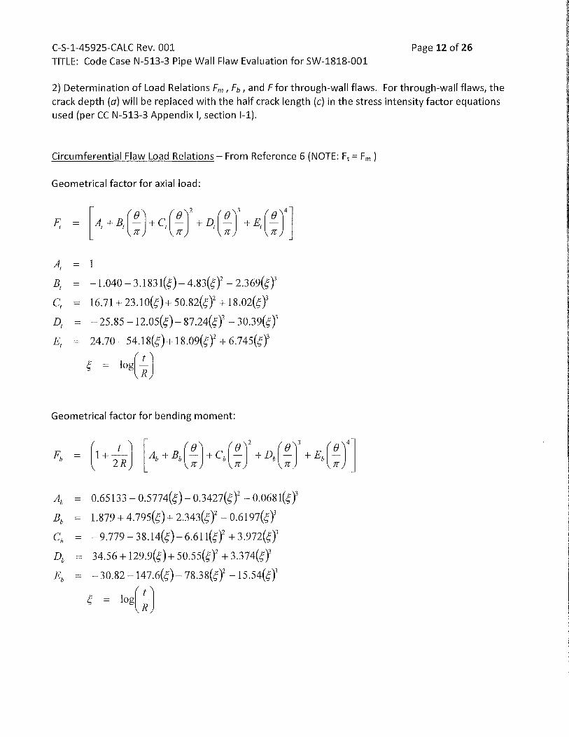
2} Determination of Load Relations Fm, Fb, and F for through-wall flaws. For through-wall flaws, the crack depth (a) will be replaced with the half crack length (c) in the stress intensity factor equations used (per CC N-513-3 Appendix I, section 1-1).
Circumferential Flaw Load Relations- From Reference 6 (NOTE: Ft = Fm )
Geometrical factor for axial load:
AI = 1
Bt = -I.o4o- 3.I831(c;)- 4.83(c;Y- 2.369(c;Y
cl = 16.71 + 23.1o(c;)+ 50.82(c;Y + 18.o2(c;Y
Dt = -25.85 -12.o5(c;)- 87.24(c;Y- 30.39(c;)3
Et = 24.7o- 54.18(c;)+ 18.o9(c;Y + 6.745(c;Y
c; = log(~)
Geometrical factor for bending moment:
Ab = o.65133- o.5774(c;)- o.3427(c;Y- o.o681(c;Y
Bb = 1.879 + 4.795(c;)+ 2.343(c;Y- o.6197(c;)3
cb = -9.779- 38.14(c;)- 6.611(c;Y + 3.972(c;Y
Db = 34.56 + 129.9(c;)+ 5o.55(c;Y + 3.374(c;Y
Eb = -30.82 -147.6(c;) -78.38(c;Y -15.54(c;Y
c; = log(~)
C-S-1-45925-CALC Rev. 001
TITLE: Code Case N-513-3 Pipe Wall Flaw Evaluation for SW-1818-001
Lcirc = 3.00 inches
c = Lcirc /2 = 1.50 inches
OD = 24 inches
t = 0.280 inches (Note: surrounding "good" wall- not nominal)
R = (OD- t) I 2 = 11.860 inches
Page 13 of 26
R/t = 42.357 NOTE: for R/t ratio> 20, the Equations for Ft and Fb become increasing conservative.
The Structural Factors for Circumferential Flaws per C-2621 are as follows:
Service Level Membrane Stress,
SFm
A 2.7 B 2.4 c 1.8
D 1.3
General Notes:
Bending Stress,
SFb
2.3 2.0 1.6
1.4
1} Unless there is evidence of a base metal repair or other wall repair history and in consideration of low operating temperature, K1r is assumed to be 0.00.
2} K1m and Ktb will be calculated for Service Levels A {NormaiL B {UpsetL C {Emergency} and D {Faulted}.
C-S-1-45925-CALC Rev. 001 Page 16 of 26 TITLE: Code Case N-513-3 Pipe Wall Flaw Evaluation for SW-1818-001
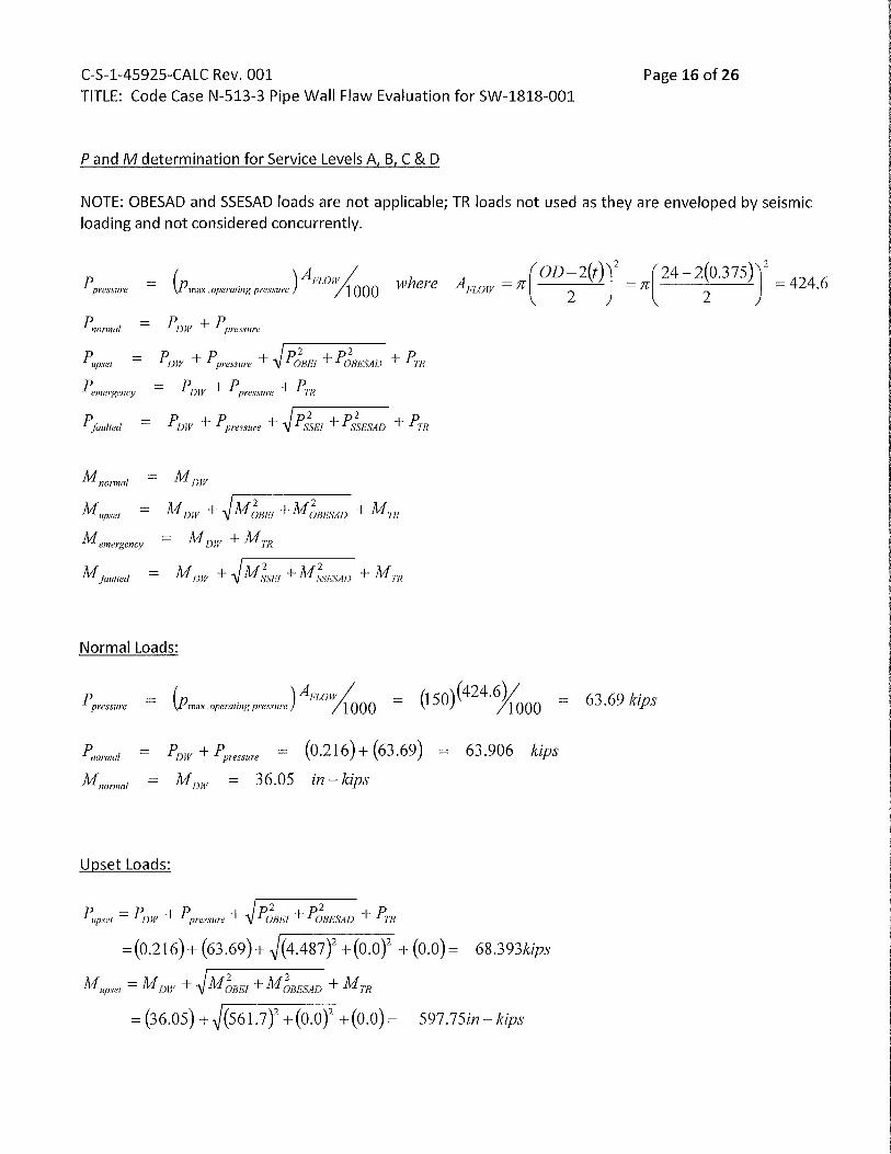
P and M determination for Service Levels A, B, C & D
NOTE: OBESAD and SSESAD loads are not applicable; TR loads not used as they are enveloped by seismic loading and not considered concurrently.
ppressure ( )Arwfj{c Pmax.operating pressure 1000 where
K I = (1.3)((69.72%n(11 .860)(0.280))}n(1.50))os (1.115) +
[(1.4{(629.45)1( )2 ( )J + (o.o)](n(1.5o))05
(1.123) = \ 1 n 11.86o o.28o
K 1 = 10.5155+17.3625=27.878ksi.Jt;;.
Summary of calculated 1<1 values for the identified Circumferential through-wall flaw
Normal Upset Emergency Faulted
K, ksi-Jii;. 21.650 42.596 19.911 27.878
C-S-1-45925-CALC Rev. 001 Page 20 of 26 TITLE: Code Case N-513-3 Pipe Wall Flaw Evaluation for SW-1818-001
4} Determination of actual flaw stress intensity factor K1 for Axial Flaws {Ref. C-7400 I C-4312)
KI = Kim +Kir ~where
Krm = (S F,11 XJJRm/t)(rcajQ)05 (F) K 1,. = K1 from residual stresses at the flaw location
where
F is the structural factor from C - 2622 - see below
a is flaw depth which for through - wall flaws is equal to c the half crack length
p is the maximum operating pressure, kips
S F,11
, R111
, t previously defined/derived
Q = 1 + 4.593(a/lY65 = 1.0 (set to unity per CC N- 513-3 Appendix I for through- wall flaws)
The Structural Factor for Axial Flaws per C-2622 are as follows:
Service Level Membrane Stress,
A 2.7 B 2.4 c 1.8
D 1.3
General Notes: 3} Unless there is evidence of a base metal repair or other wall repair history and in consideration of
low operating temperature, K1r is assumed to be 0.00. 4) K1m will be calculated for Service Levels A {Normal}, B {Upset}, C {Emergency) and D {Faulted).
C-S-1-45925-CALC Rev. 001 TITLE: Code Case N-513-3 Pipe Wall Flaw Evaluation for SW-1818-001
Determination of actual flaw stress intensity factor K1 for Axial Flaws
KI = Kim+ Klr
where
Kim = (s F;,.XPR,)t)(1ta/I.Ot (F)
K 1, = 0.0
Normal K1 Determination (All equation terms previously derived)
Summary of calculated K1 values for the identified Axial through-wall flaw
Normal Upset Emergency Faulted
K, ksiJb;. 19.383 17.229 12.922 9.333
C-S-1-45925-CALC Rev. 001 Page 23 of 26 TITLE: Code Case N-513-3 Pipe Wall Flaw Evaluation for SW-1818-001
5) CONCLUSION -Prepared input for use in a revised Operability Determination, if required for the projected flaw size of 0.75 inch axial by 3.0 inch circumferential.
FLAW STABILITY CHECK Flaw Type Service Load Stress Intensity Factor Allowable I Calculated
K1 (ksiJi;;) Calculated Allowable
Circumferential Normal 21.650 96.858 4.47
Upset 42.596 96.858 2.27
Emergency 19.911 96.858 4.86
Faulted 27.878 96.858 3.47
Axial Normal 19.383 96.858 5.00
Upset 17.229 96.858 5.62
Emergency 12.922 96.858 7.50
Faulted 9.333 96.858 10.38
The calculated Stress Intensity Factors include the required structural factors prescribed by Code Case N-513-3 and ASME Section XI, Division 1 Article C-2620. The acceptable calculated stress intensity factors
ensures the acceptability of the pipe for temporary service.
The Structural Factors for Circumferential Flaws per C-2621 are as follows:
Service Level Membrane Stress, Bending Stress,
SFm SFb
A 2.7 2.3
B 2.4 2.0
c 1.8 1.6
D 1.3 1.4
The Structural Factor for Axial Flaws per C-2622 are as follows:
Service Level Membrane Stress,
A 2.7 B 2.4 c 1.8
D 1.3
A review ofthe Flaw UT data identified an adjacent minimum remaining pipe wall (tp) of 0.280 inch. This is a non-planar flaw and per CC N-513-3 must be greater than the N-513-3 derived minimum wall.
C-S-1-45925-CALC Rev. 001 TITLE: Code Case N-513-3 Pipe Wall Flaw Evaluation for SW-1818-001
tP = (0.280)~ tmin = (0.105)(calculatedonsht.9)
4.0 ASME Code Required Minimum Wall Thickness per CC-597
Determine minimum wall required for Design Pressure
P = Design operating pressure at flaw location = 150 psi Ref. Source= 4.4.17.04F-CALC Rev. 6 TIP Sht. U-12
0 0 =Piping outside diameter= 24 inches 5 =pipe material allowable stress at Design Temperature= 17100@ 200°F
Page 24 of 26
y = 0.4, except where Do< 6 (tm ) (Note: use 0.4 then verify that this value is acceptable)
= (150)(24) = 0.105inch
2 (17100+ 0.4(150))
= 24 < 6(0.105) = 0.630 useof0.4isacceptable
Determine minimum wall required for mechanical loading
The effect on piping stresses at the reduced wall location must be evaluated with consideration given to changes in the pipe metal area, pipe inside area, section modulus and stress intensification factor.
EQ. 8 = P D0 I 4 t pred + 0. 75 i [ ( Mb + P Ao 8 ) I Zmin ) ] :S 1.143 S
with Mb based upon deadweight loads only.
EQ. 9 = P D0 I 4 t pred + 0.75 i [ ( Mb + P Ao 8) I Zmin)] :S 1.143 X 1.2 S = 1.372 S
with Mb based upon deadweight, OBE seismic and transient loads, as applicable.
For the evaluation the derived minimum wall thickness for pressure is used for tpred·
A0 =total cross-sectional area of pipe based on nominal outside diameter, n Do 2 I 4 = 452.4 in. 2
8 = nominal distance between the center of the pipe and the neutral axis of the thinned piping section
= t nom- t pred = 0.375 -0.105 = 0.270 in.
Z min= I min I R max where R max= (Do I 2) + 8 = 12.270 in.
C-S-1-45925-CALC Rev. 001 Page 25 of 26 TITLE: Code Case N-513-3 Pipe Wall Flaw Evaluation for SW-1818-001
where I min= 0.0491 [ Do4- (Do- 2 tprect )4
] = 562.72 in.4
Z min = 45.861 in.3
The moment loading terms were extracted previously and are displayed on Sht. 6 (Note: MR conservatively used)
For Deadweight Mb = (12) 3004 = 36048 in-lbs. For Total Mb = Deadweight+ SRSS (OBEI & OBEA) + TR = (12)(3004 + 46805.5) = 597714 in.-lbs.
Intensification factor= 1.0; Considering the wall thinning, the factor is re-calculated as follows: Not required due to flaw location being in straight pipe. Note: 0.75i cannot be less than 1.0 per the ASME Code.
EQ. 8 = P Do I 4 t pred + 0.75 i [ ( Mb + P Ao 0) I Zmin)] ~ 1.143 S
~ Simplified stress evaluation is acceptable with calculated stresses within Code allowable. Check for cyclic operation.
D Simplified stress evaluation is not acceptable. Detailed review performed in calculation ___ _
Evaluation for Cyclic Operation
Is t pred = 0.105 > 0.75 t nom= 0.281 ? DYES ~NO
Is N (Equivalent Full Temperature Cycles) at time of next inspection ~ 150 ? ~YES D NO
If the response to both questions is YES, piping stress equations that include thermal expansion and anchor movements stresses need not be evaluated. If not, continue below.
The thermal expansion and anchor movement stress at the inspection location from the referenced analysis of record is not applicable (cold system; no anchor movement).
The Stress Range Reduction Factor (f) used in analysis is 1.0
Is N (Equivalent Full Temperature Cycles)~ 650? ~YES D NO
If the response is YES- no further cyclic evaluation is required; component is acceptable.
C-S-1-45925-CALC Rev. 001 Page 26 of 26 TITLE: Code Case N-513-3 Pipe Wall Flaw Evaluation for SW-1818-001
7.0 REVIEWERS COMMENTS AND RESOLUTIONS
Line by line check performed.
Any and all reviewer comments, corrections, and changes have been reviewed by the Cognizant Design Engineer and have, with the mutual consent of the reviewer, been incorporated.