NEXTera ENERGYARO September 4, 2013 10 CFR 50.55a Docket No. 5 0-443 SBK-L-13173 U.S. Nuclear Regulatory Commission Attention: Document Control Desk One White Flint North 11555 Rockville Pike Rockville, MD 20582 Seabrook Station Relief Request RA-13-001, Revision 1 Proposed Alternative in Accordance with 10 CFR 50.55a (a)(3)(ii) References: 1. NextEra Energy Seabrook conference call with NRC requesting relief to perform a temporary, non-ASME Code repair to Seabrook Unit 1 Service Water System, August 30, 2013. 2. NextEra Energy Seabrook conference call with NRC providing responses to NRC questions regarding a temporary, non-ASME Code repair to Seabrook Unit 1 Service Water System, August 30, 2013. 3. NRC conference call with NextEra Energy Seabrook granting relief to perform a temporary, non-ASME Code repair to Seabrook Unit 1 Service Water System, August 31, 2013. Pursuant to 10 CFR 50.55a(a)(3)(ii) NextEra Energy Seabrook, LLC (NextEra Energy Seabrook) requested relief to perform a temporary, non-ASME code repair to the Seabrook Station Unit 1 Service Water (SW) system. The circumstances regarding this request were discussed with the NRC staff in conference calls on August 30, 2013 (References 1 and 2). The NRC granted relief to perform the requested repair in a conference call on August 31, 2013 (Reference 3). Justification for the temporary repair of the Seabrook Unit 1 SW piping is provided in the attachment to this letter, and also includes the responses to the NRC questions regarding the issue. NextEra Energy Seabrook, LLC, P.O. Box 300, Lafayette Road, Seabrook, NH 03874
Transcript
NEXTeraENERGYARO
September 4, 2013
10 CFR 50.55a
Docket No. 5 0-443SBK-L-13173
U.S. Nuclear Regulatory CommissionAttention: Document Control DeskOne White Flint North11555 Rockville PikeRockville, MD 20582
Seabrook Station
Relief Request RA-13-001, Revision 1Proposed Alternative in Accordance with 10 CFR 50.55a (a)(3)(ii)
References:
1. NextEra Energy Seabrook conference call with NRC requesting relief to performa temporary, non-ASME Code repair to Seabrook Unit 1 Service Water System,August 30, 2013.
2. NextEra Energy Seabrook conference call with NRC providing responses to NRCquestions regarding a temporary, non-ASME Code repair to Seabrook Unit 1Service Water System, August 30, 2013.
3. NRC conference call with NextEra Energy Seabrook granting relief to perform atemporary, non-ASME Code repair to Seabrook Unit 1 Service Water System,August 31, 2013.
Pursuant to 10 CFR 50.55a(a)(3)(ii) NextEra Energy Seabrook, LLC (NextEra EnergySeabrook) requested relief to perform a temporary, non-ASME code repair to theSeabrook Station Unit 1 Service Water (SW) system. The circumstances regarding thisrequest were discussed with the NRC staff in conference calls on August 30, 2013(References 1 and 2). The NRC granted relief to perform the requested repair in aconference call on August 31, 2013 (Reference 3). Justification for the temporary repairof the Seabrook Unit 1 SW piping is provided in the attachment to this letter, and alsoincludes the responses to the NRC questions regarding the issue.
United States Nuclear Regulatory CommissionSBK-L- 13 173/Page 2
Seabrook Station is in the third 10-year inservice inspection interval which ends August18, 2020.
This request is similar to the relief granted to Southern Nuclear Operating Company, Inc.,for the Edwin I. Hatch Nuclear Plant, Unit 1 (ML12058A413) and Shearon HarrisNuclear Power Plant, Unit 1 (ML1 10601120).
There are no commitments being made in this submittal.
If you have any questions regarding this submittal, please contact Mr. Michael Ossing,Licensing Manager, at (603) 773-7512.
Sincerely,
NextEra Energy Seabrook, LLC
Lensing Manyer
Attachment:
Request RA- 13-001, Revision 1, Proposed Alternative in accordance with10 CFR 50.55a (a)(3)(ii)
cc:
W. M. Dean, NRC Region I AdministratorJ. G. Lamb, NRC Project ManagerP. C. Cataldo, NRC Senior Resident Inspector
Attachment to SBK-L- 13173
Request RA-13-001, Revision IProposed Alternative in accordance with 10 CFR 50.55a (a)(3)(ii)
SEABROOK STATION UNIT 1 10 CFR 50.55a Relief Request RA-13-001 Revision 1.0Proposed Alternative in Accordance with 10 CFR 50.55a(a)(3)(ii)
1. ASME Code Components Affected
The affected piping is the "B" Train 24-inch diameter service water supply pipe, line numberSW-I1802-004-153-24", which supplies cooling water to the Primary Component Cooling Water(PCCW) Heat Exchanger CC-E- 17-B for the purpose of removing heat from systems andcomponents during normal plant operations and emergency plant evolutions. The Codecomponent associated with this request is a Class 3 piping component in the Service Water (SW)system in which a flaw has been detected. There is one area affected by a localized flaw.
1.1 System Details:
ASME Code Class: Class 3System: Service Water SystemCategory: Moderate Energy Piping
1.2 Component Descriptions:
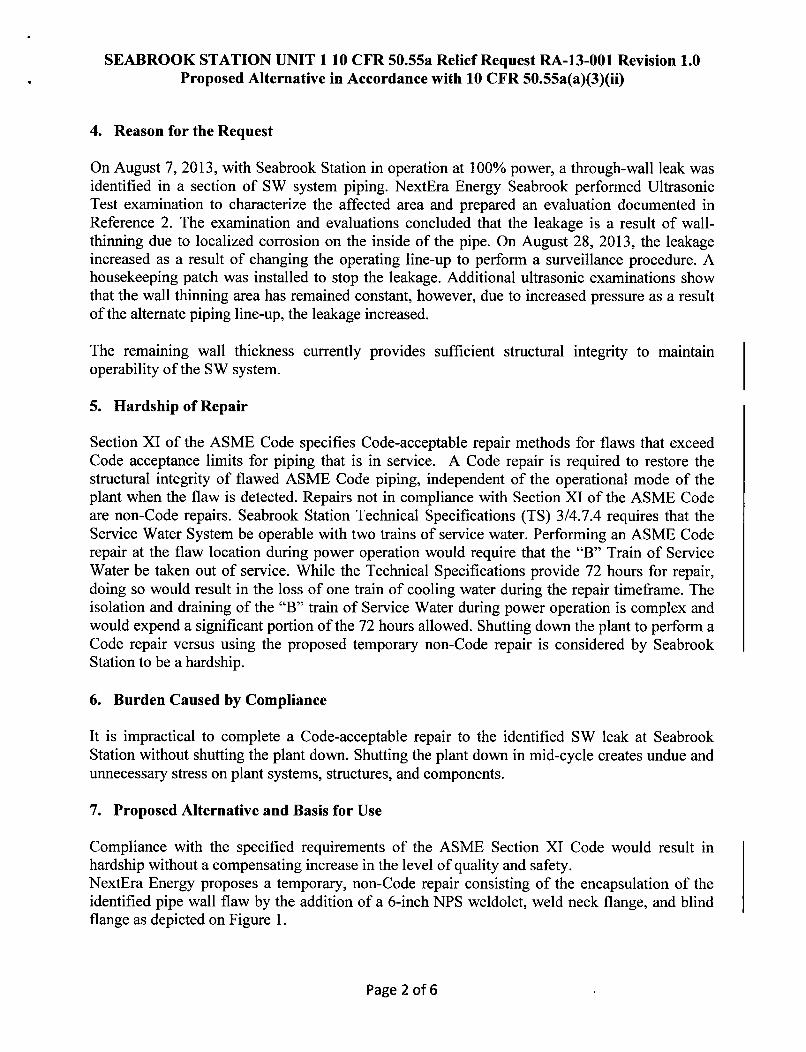
The component in question is 24-inch Nominal Pipe Size (NPS) carbon steel piping with anominal wall thickness of 0.375-inch. The application of this alternative is to perform atemporary, non-Code repair to the SW piping. This non-Code repair will consist of the additionof a 6-inch nominal diameter weldolet, weld-neck flange, and blind flange over the identifiedlocalized flawed area. The general configuration for the repair is shown in Figure 1.
2. Applicable Code Edition and Addenda
Seabrook Station is currently in the third 10-year Inservice Inspection (ISI) interval. TheAmerican Society of Mechanical Engineers (ASME) Boiler and Pressure Vessel Code (Code) ofrecord for the current 10-year ISI interval is Section XI, 2004 Edition, with no Addenda(Reference 1) for the Repair/Replacement Program.
3. Applicable Code Requirement
The applicable Code Sections for which the relief is requested from is ASME Code Section XI,2004 Edition, with no Addenda, Section IWA-4412.
IWA-4412 states: "Defect removal shall be accomplished in accordance with the requirements ofIWA-4420."
The identified defect will not be removed during operation of the "B" Train of Service Waterbecause doing so would result in a significant leak rate through a larger area resulting from theremoval of degraded pipe wall. Therefore relief is being requested to perform a temporary non-Code repair.
Page I of 6
SEABROOK STATION UNIT 110 CFR 50.55a Relief Request RA-13-001 Revision 1.0Proposed Alternative in Accordance with 10 CFR 50.55a(a)(3)(ii)
4. Reason for the Request
On August 7, 2013, with Seabrook Station in operation at 100% power, a through-wall leak wasidentified in a section of SW system piping. NextEra Energy Seabrook performed UltrasonicTest examination to characterize the affected area and prepared an evaluation documented inReference 2. The examination and evaluations concluded that the leakage is a result of wall-thinning due to localized corrosion on the inside of the pipe. On August 28, 2013, the leakageincreased as a result of changing the operating line-up to perform a surveillance procedure. Ahousekeeping patch was installed to stop the leakage. Additional ultrasonic examinations showthat the wall thinning area has remained constant, however, due to increased pressure as a resultof the alternate piping line-up, the leakage increased.
The remaining wall thickness currently provides sufficient structural integrity to maintainoperability of the SW system.
5. Hardship of Repair
Section XI of the ASME Code specifies Code-acceptable repair methods for flaws that exceedCode acceptance limits for piping that is in service. A Code repair is required to restore thestructural integrity of flawed ASME Code piping, independent of the operational mode of theplant when the flaw is detected. Repairs not in compliance with Section XI of the ASME Codeare non-Code repairs. Seabrook Station Technical Specifications (TS) 3/4.7.4 requires that theService Water System be operable with two trains of service water. Performing an ASME Coderepair at the flaw location during power operation would require that the "B" Train of ServiceWater be taken out of service. While the Technical Specifications provide 72 hours for repair,doing so would result in the loss of one train of cooling water during the repair timeframe. Theisolation and draining of the "B" train of Service Water during power operation is complex andwould expend a significant portion of the 72 hours allowed. Shutting down the plant to perform aCode repair versus using the proposed temporary non-Code repair is considered by SeabrookStation to be a hardship.
6. Burden Caused by Compliance
It is impractical to complete a Code-acceptable repair to the identified SW leak at SeabrookStation without shutting the plant down. Shutting the plant down in mid-cycle creates undue andunnecessary stress on plant systems, structures, and components.
7. Proposed Alternative and Basis for Use
Compliance with the specified requirements of the ASME Section XI Code would result inhardship without a compensating increase in the level of quality and safety.NextEra Energy proposes a temporary, non-Code repair consisting of the encapsulation of theidentified pipe wall flaw by the addition of a 6-inch NPS weldolet, weld neck flange, and blindflange as depicted on Figure 1.
Page 2 of 6
SEABROOK STATION UNIT 1 10 CFR 50.55a Relief Request RA-13-001 Revision 1.0Proposed Alternative in Accordance with 10 CFR 50.55a(a)(3)(ii)
7.1 Flaw Sizing and Characterization
On August 7, 2013 an Ultrasonic Test (UT) examination was performed at an identified throughwall leak on line SW-1802-004-153-24". The area was identified by discovery of a slow (severaldrops per minute) leak. The examination revealed that the through wall leak at this location wasthe result of a single isolated flaw that appears to be related to corrosion. Encoded UT data wascollected at this location and was used to evaluate the through wall leakage area. A 3-inch by 6-inch area surrounding the flaw was selected for the encoded examination. This encoded areaencompassed the entire flawed area. Normal intermittent responses could not be received in anarea specifically bounded by where the inside surface response was initially lost. This resulted ina conservative bounded flaw area of 2.327-inches circumferentially by 1.500-inches axially.Wall thickness readings could not be obtained within this region. However, it was identified thatthere is an abrupt increase in thickness to nominal wall (0.375 inch) and above outside thisregion.
During the angle beam exam, the flaw could be seen in all four directions which is not typical forplanar flaws. For structural evaluation purposes the flaw was considered non-planar. At the timeof the August 7, 2013 examination no visible through wall hole was identified. On August 20,2013 an increase in through wall flow was identified. A subsequent UT examination wasperformed. It concluded that the bounding area of 2.327-inches by 1.500-inches remained thesame with no reportable thickness recorded in this area. However, a visible through wall holeestimated to be 0.250-inches in diameter was identified. In accordance with ASME Code CaseN-513-3, the entire circumference of the piping at the through wall leak location was alsoexamined with no other defects identified.
7.2 Degradation Mechanism
As discussed in Section 7.1 above, based upon the Non-Destructive Examination (NDE), thelocalized flaw appears to be seawater corrosion related. See further discussion on this in Section7.4.
7.3 Flaw Evaluation
A flaw evaluation, in accordance with ASME Code Case N-513-3, was performed with thethrough wall flaw size assumed to be the bounding area of 2.327-inches by 1.500-inches. Theevaluation concluded that structural integrity is maintained. This evaluation is provided inReference 2, a copy of which is attached. In accordance with Code Case N-513-3, augmentedinspections were scheduled to be performed to determine the extent of condition.
7.4 Flaw Growth Rate
As previously stated in Section 7.2, the cause of the degradation is from localized corrosion. Thetypical corrosion rate used in Seabrook Station Service Water piping evaluations is 30 mils peryear (mpy). However, the current identified wall defect resides in piping which was recentlyreplaced during Refueling Outage 14 during April 2011, concluding that an accelerated
Page 3 of 6
SEABROOK STATION UNIT 1 10 CFR 50.55a Relief Request RA-13-001 Revision 1.0Proposed Alternative in Accordance with 10 CFR 50.55a(a)(3)(ii)
(presently unknown) mechanism exists within the bounding area. The NDE identified nominal(and above) pipe wall thickness around the bounding area. Based upon this, it is assumed thatwhile further degradation will occur within the bounding area, the surrounding area wall loss willbe such that the ASME Code required minimum pipe wall thickness, calculated to be 0.105-inchin Reference 2, will not be violated during the duration of the proposed temporary non-Coderepair. To provide further assurance, a 6-inch weldolet has been selected for use.
The sizing of the weldolet (6 inch nominal) was based upon the identified wall thickness of thepiping and its installation position with respect to the bounded flaw size (2.327 by 1.5 inch). Theweldolet will be welded to pipe wall thickness verified to be of a thickness of 0.375 inch orbetter. The typical corrosion rate used by Seabrook is 30 mils per year. To proactively addressthe corrosion potential within the bounded area, a factor of 4 is applied resulting in a rate of 120mils per year. Although the installation duration is less than a year (next refueling outage isSpring 2014) 120 mils is used. The resulting pipe wall under the weldolet and weldment willtherefore be reduced from to 0.375 - 0.120 = 0.255 inch. The ASME Section III Coderequirement for minimum pipe wall is 0.105 inch, calculated in calculation C-S-1-45893. As thepipe wall with future metal loss, calculated to be 0.255 inch, exceeds the Code minimum of0.105 inch, structural integrity of the repair will be maintained. The 6.6875 inch inside diameterof the weldolet in relationship with the major axis dimension of the bounded flaw (2.327 inch)provides sufficient metal such that further corrosion will not affect the integrity of the repair.
7.5 Repair Components
The design pressure and temperature of the Service Water piping system is 150 psi and 200degrees F. Normal operating pressure is 75 psi and Normal operating temperature is 65 degrees Fmaximum and 35 degrees F minimum. The repair components, weldolet, weld neck flange andblind flange design conforms to these temperature and pressure requirements. The weldolet isconstructed from ASME SA material and meets the ASME Section III ND requirement forbranch connections. The welding will be performed using a qualified procedure that meets theASME Section IX requirements for an open root, full penetration weld. The branch connectionwill meet the ASME Section III ND requirements for fabrication. The pre-installation NDErequirements for the weldolet consists of the verification of ASME material, the verification ofproper weld joint fit-up and a final Visual and Penetrant Testing exam of the final weld. The postinstallation NDE requirements consist of a VT-2 for leakage in accordance Section XI, IWA-5000. The acceptance criteria are in accordance with the original construction code, ASMESection III ND, requirements. The NDE examination methods performed will meet the ASMESection XI, IWA-4500 requirements.
7.6 Piping System Impact
The weight of the repair components is determined as follows: 14.20 lbs (weldolet) + 27 lbs(weld neck flange with bolting) + 26 lbs (blind flange) + 10 lbs (water content) = 77.2 lbs.The pipe supports adjacent to the defective area are:1802-SG- 12 - Vertical support (±) approximately three feet downstream of the defect area(providing strainer anchorage)
Page 4 of 6
SEABROOK STATION UNIT 1 10 CFR 50.55a Relief Request RA-13-001 Revision 1.0Proposed Alternative in Accordance with 10 CFR 50.55a(a)(3)(ii)
1802-RG-06 - Lateral support (±) approximately 1.5 feet downstream of the defect area on thestrainer bypass piping1802-SG-08 - Vertical support (+) approximately 9.0 feet downstream of the defect area on thestrainer bypass piping.1802-SG-03 - Vertical and lateral support (±) approximately 19 feet upstream of the defect area.A review of the pipe support design documentation has concluded that the existing pipe supportscheme can accommodate the weight addition of 77.2 lbs.
8. Duration of Proposed Alternative
The temporary non-Code repair to the Seabrook Station SW system will remain in place until thenext Refueling Outage (OR16) scheduled for Spring 2014.
9. Post Repair Monitoring
As discussed in Section 7.1, nominal pipe wall exists around the bounding area of 2.327-inchesby 1.500-inches. The proposed temporary non-Code repair will be installed on this nominal pipewall. Periodic UT inspections of no more than 30 day intervals around the installed weldolet willbe performed to identify wall loss propagating outside the encompassed area.
10. Precedents
1) NRC letter from N. Salgado to M. J. Ajluni of Southern Nuclear Operating Company,Inc., "Edwin I. Hatch Nuclear Plant, Unit 1, Safety Evaluation of Relief Request HNP-ISI-ALT- 14, Version 2, for the Fourth 10-Year Inservice Inspection Interval, TemporaryNon-Code Repair of Service Water Piping" (TAC No. ME7366)( (ML 12058A413)
2) NRC letter from D. A. Broaddus to C. Burton of Shearon Harris, "Shearon HarrisNuclear Power Plant, Unit 1 - Relief Request 13R-08, Temporary Non-Code Repair ofService Water Supply System Piping" (TAC No. ME4750) (ML1 10601120)
11. References
1) American Society of Mechanical Engineers (ASME) Boiler & Pressure Vessel Code,Section XI, 2004 Edition, no Addenda.
2) Seabrook Station Calculation C-S-1-45893-CALC Rev. 000 "Code Case N-513-3 PipeWall Flaw Evaluation for: SW- 1802-004-153-24" (attached).
Page 5 of 6
SEABROOK STATION UNIT 110 CFR 50.55a Relief Request RA-13-001 Revision 1.0Proposed Alternative in Accordance with 10 CFR 50.55a(a)(3)(ii)
Code Case N-513-3 Pipe Wall Flaw Evaluation for: SW-1802-004-153-24"
TITLE
C-S-1-45893 0 NA SWCALCULATION # REV. # Vendor Calc# System
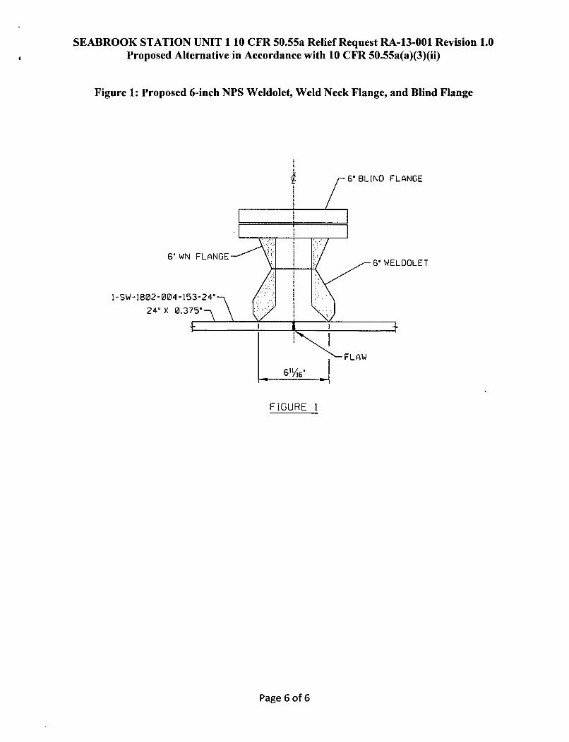
Executive Summary
The through-wall pipe flaw Identified and documented in AR# 01895334 has been evaluated inaccordance with NRC CC N-513-3 and found to be stable. Calculated Stress Intensity Factors for allService conditions are within the Code Case specified allowable with the applicable structuralfactors applied.The ASME Code required minimum pipe wall thickness for both Design Pressure as well asmechanical loading is tm = 0.105 inch.The N-513-3 derived minimum wall for the adjacent non-planar flaw region is 0.120 inch.
Does this calculation:1. Support a MJR [DCR], MNR [MMOD], an independent review method Yes EINo 0
for a DCP, or confirm test results for an installed DCP? If yes, indicatethe MJR [DCR], MNR [MMOD] number and/or Test Procedure number.
2. Support independent analysis? If yes, indicate the procedure, work Yes [@No 0control or other reference it supports.Supports the response to AR# 01895334
3. Revise, supersede, or void existing calculations? If yes, indicate the Yes E1No l]calculation number and revisions.
4. Involve OQAT related systems, components or structures? Yes NNo 0l5. Impact the licensing basis, including technical specifications, Yes LNo 0
NUHOMS® HD System Technical Specifications, technicalrequirements, UFSAR, NUHOMS® HD System Final Safety AnalysisReport, procedures or licensing commitments? If yes, identifyappropriate change documents.
Approvals (Signature) .
Preparer H. W. Menteld2' -7 /'O_ Date: . 13Independent Verifier S.'Das , .. , Date: I 2Supervisor/Manager B. E. Brown Date: f; /--
Sheet I
NADC FORM 5ARev. 46
Page 1 of 1
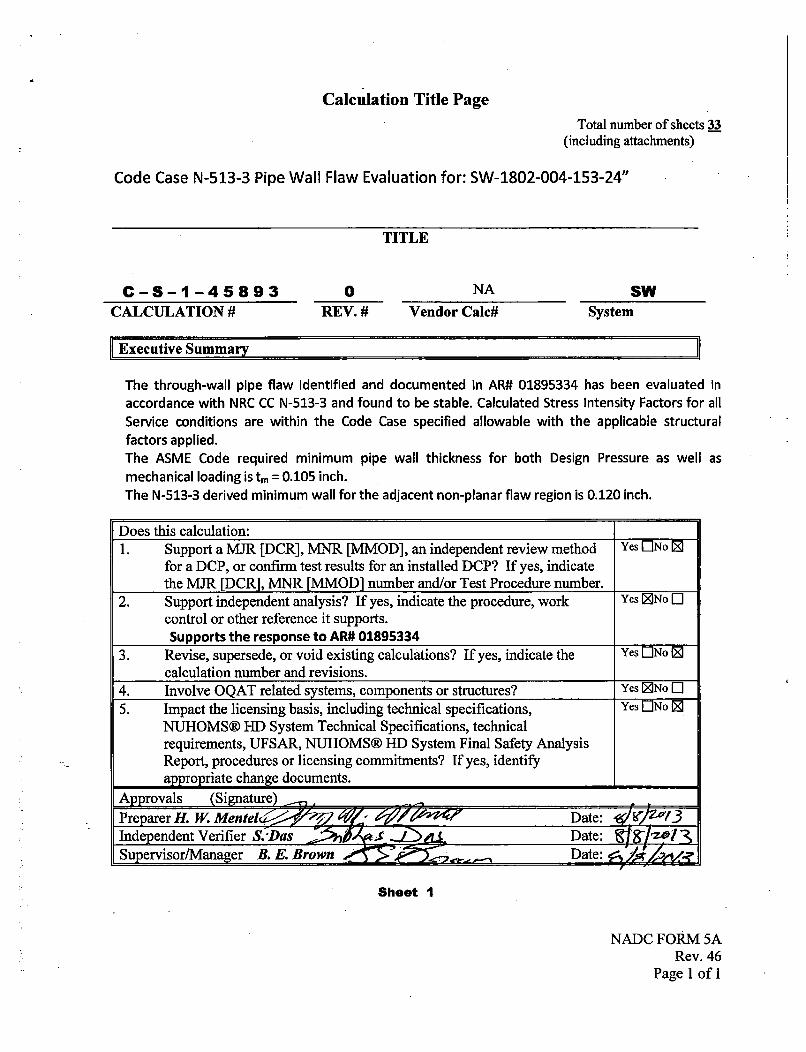
Calculation Revision Control Sheet
CALCULATION NUMBER: C - S - 1- 4 5 8 9 3 PAGE 2
CALC. REV. TOTAL NO. OF (LIST AFFECTED PAGES)NO. PAGES
Shts. 1 through 26 ADDED: n/aPlus attachment A Shts.1 through 7
REPLACED: n/a
DELETED: n/a
PURPOSE:
ADDED:
REPLACED:
DELETED:
PURPOSE:
ADDED:
REPLACED:
DELETED:
PURPOSE:
ADDED:
REPLACED:
DELETED:
PURPOSE:
ADDED:
REPLACED:
DELETED:
NADC FORM 5BRev. 45
Page 1 of 1
CALCULATION NUMBER Sht. No] Revision Level Preparer/Date Verifier/Date
C-S-1-45893 3 0 HWMe 8/8/13 S. Das 8/8/13
TITLE: Code Case N-513-3 Pipe Wall Flaw Evaluation
CALCULATION FORMAT
TOPIC Sheet Number(s)Calculation Cover Sheet 1
Calculation Revision Control Sheet 2
Calculation Format 3
1.0 PURPOSE 4
2.0 SUMMARY OF RESULTS 4
3.0 REFERENCES / DESIGN INPUTS 5
4.0 ASSUMPTIONS 5
5.0 METHOD OF ANALYSIS 6Background 6Method 6
6.0 BODY OF CALCULATION 71.0 Scope - Applicability 72.0 Scope - Procedure 83.0 Flaw Evaluation 8
Background 8
Evaluation 111) Determination of Flaw Acceptance Criteria, K, 112) Determination of Load Relations Fm, Fb, and F 123) Determination of actual flaw stress Intensity factor K, for 15
Circumferential Flaw4) Determination of actual flaw stress Intensity factor K, for 20
Axial Flaw5) CONCLUSION - Prepared Input for Operability Determination 23
4.0 ASME Code Required Minimum Wall Thickness per CC-597 24
7.0 REVIEWERS COMMENTS AND 26RESOLUTION
-.8.0 ATTACHMENTS 26
Total Number of ATTACHMENT Sheets 7 sheets
Total Number of Calculation Sheets 33 sheets(including attachment sheets)
CALCULATION NUMBER Sht. No.
C-S-1-45893 4
TITLE: Code Case N-513-3 Pipe Wall Flaw Evaluation
Revision Level Preparer/Date Verifier/Date
0 HWMe 8/8/13 S. Das 8/8/13
1.0 PURPOSE
A through-wall flaw has been identified in pipe line SW-1802-004-153-24". The identification of thisflaw has been entered into the Seabrook Station Corrective Action Program via Action Request (AR)01895334.
The purpose of this calculation is to perform a wall thickness flaw evaluation in accordance with theASME Boiler and Pressure Vessel Code Case N-513-3. This evaluation will determine whether or notthe identified flaw is stable and provide input into the associated system operability determination.Furthermore this evaluation will identify recommended actions with regards to repair/replacementactivities of the subject component.
The subject piping is classified as ANS Safety Class 3; Seismic Category I.
2.0 SUMMARY OF RESULTS
EXECUTIVE SUMMARY:
The through-wall pipe flaw identified and documented in AR# 01895334 has been evaluated inaccordance with NRC CC N-513-3 and found to be stable. Calculated Stress Intensity Factors for all Serviceconditions are within the Code Case specified allowable with the applicable structural factors applied.The ASME Code required minimum pipe wall thickness for both Design Pressure as well as mechanicalloading is tm = 0.105 inch.The N-513-3 derived minimum wall for the adjacent non-planar flaw region is 0.120 inch.
CALCULATION NUMBER Sht. No,C-S-1-45893 5
Revision Level Preparer/Date Verifier/Date
0 HWMe 8/8/13 S. Dos 8/8/13
TITLE: Code Case N-513-3 Pipe Wall Flaw Evaluation
3.0 REFERENCES I DESIGN INPUTS
1) Action Request # 018953342) Code Case N-513-3 "Evaluation Criteria for Temporary Acceptance of Flaws in Moderate Energy
Class 2 or 3 Piping, Section XI, Division 1", Cases of ASME Boiler and Pressure Vessel Code, January26, 2009.
3) ASME Boiler and Pressure Vessel Code, Section III 1983 Edition. (2007 Edition used for materialproperties).
1", Revision 16, Nuclear Regulatory Commission, October 2010.6) Y. Takahashi, "Evaluation of Leak-Before-Break Assessment of Pipes with a Circumferential
Through-Wall Crack. Part 1: Stress Intensity Factor and Limit Load Solutions," International Journalof Pressure Vessels and Piping, 79, 2002.
12) Design Control Manual, NADC Rev. 5913) Piping Isometric: SW-1802-09 Rev. 714) Design Change Isometric SK-EC156603-2001 Rev. 215) "Piping Design and Engineering" Fourth Edition, Revised 1973 from ITT Grinnell Corporation.16) Piping Stress Analysis of Record C-S-1-45718-CALC Rev. 717) Calculation 4.4.17.04F-CALC Rev. 6
4.0 ASSUMPTIONS
None
CALCULATION NUMBER Sht. No.
C-S-1-45893 6
TITLE: Code Case N-513-3 Pipe Wall Flaw Evaluation
Revision Level Preparer/Date Verifier/Date
0 HWMe 8/8/13 S. Das 8/8/13
5.0 METHOD OF ANALYSIS
Hand Calculation
Background:
The subject piping is SW-1802-004-153-24", and depicted on isometric SW-1802-09. the latest designchange isometric is SK-EC156603-2001.
The current analysis of record for the piping is calculation C-S-1-45718-CALC Rev. 7.Results from ADLPIPE Output SWONER4.000 dated 07/02/2013 are used.
The ADLPIPE software model node at or adjacent to the through wall leak location is 475.The following forces and moment loading has been extracted for use in this calculation.NOTE: Axial Force = Fz; Torsional moment = Mz Resultant moments MR conservatively used
Due to the nature of the hydraulic transients (pump starts/re-starts) Hydraulic Transient loads neednot be combined with seismic loading Ref: C-S-1-45718-CALC Rev. 7)Applicable stress intensification factor, i = 1.0 (Straight pipe).
Method:
Utilizing the mechanical loading shown above, the fracture toughness of the remaining pipe wall will be-.evaluated per the criteria presented in Code Case N-513-3, to determine the likelihood of further flawpropagation due to the subjective loading. Verification of flaw stability does not negate the requirementof addressingthe potential for further degradation due to salt water intrusion.
CALCULATION NUMBER Sht. Nol
C-S-1-45893 7
TITLE: Code Case N-513-3 Pipe Wall Flaw Evaluation
Revision Level Preparer/Date Verifier/Date
0 HWMe 8/8/13 S. DOS 8/8/13
6.0 BODY OF CALCULATION
1.0 Scope - Applicability:
(a) The Code Case requirements apply to ASME Section III, ANSI B31.1 and ANSI B31.7 piping classified
as Class 2 or 3.
The subject piping is classified as: ASME Section III, Subsection ND
The subject piping component is : straight pipe downstream to tee
Piping Material is: SA 106 Grade B
CAUTION
NOTE: Code Case is not applicable to the following:(1) pumps, valves, expansion joints and heat exchangers;(2) socket welds;(3) leakage through a flange joint;(4) threaded connections employing nonstructural seal welds for leakage protection.
(b) The Code Case applies to Class 2 or 3 piping whose maximum operating temperature does notexceed 200°F and whose maximum operating pressure does not exceed 275 psig.
The subject piping maximum operating temperature = 90 < 200°FThe subject piping maximum operating pressure = 171 < 275 psigReference Source for temperature / pressure conditions: Calculation 4.4.17.04F-CALC Rev. 6, Sht. U-3
(c) Flaw Evaluation criteria are permitted for pipe and tube. It cannot be used for adjoining fittings andflanges as calculations are based upon round pipe. However the criteria is applicable to that portion ofthe fitting where it transitions from pipe up to a distance of (Rot)1/ 2 from the weld centerline.
Is the flaw location adjacent to a fitting / flange weld ?Yes, but located on the straight pipe; (R.1t) 1/ 2 criteria is not applicable.
CALCULATION NUMBERC-S-1-45893
Sht. No.8
Revision Level Preparer/Date Verifier/Date
0 HWMe 818113 S. Das 818113
TITLE: Code Case N-513-3 Pipe Wall Flaw Evaluation
2.0 Scope - Procedure:
(a) The flaw geometry shall be characterized by volumetric inspection methods or by physicalmeasurement. The full pipe circumference at the flaw location shall be inspected to characterize thelength and depth of all flaws in the pipe section.
The subject flaw has been characterized by: UT examES1807.012 Form A: Ultrasonic Thickness Examination Report attached. See Attachment A
(b) Flaw Classification: Planar or NonplanarRef: a) See N-513-3 Fig. 1 -Through wall flaw geometry- all through wall flaws are planar
b) See N-513-3 Fig. 3 - Nonplanar Flaw due to Wall ThinningBased upon the description in AR# 1895334, AR photographs and the examination data documented inAttachment A, the flaw is classified is classified as non-planar.
(c) Are multiple flaws present? (circle, as applicable) NoIf the answer is yes, the interaction and combined area of loss of flaws in a given pipe section shall beaccounted for in the flaw evaluation. In accordance with Section IWA-3300 of Section XI, the adjacentflaws shall be bounded by a single rectangular or circumferential planar area.
(d) A flaw evaluation shall be performed to determine the conditions for flaw acceptance.Section 3.0 provides the accepted methods for conducting the required analysis.
3.0 Flaw Evaluation:
Background
Typically flaw evaluations are prepared for identified through wall flaws in ferritic piping.Code Case N-513-3 provides criteria for the evaluation of nonplanar flaws (Section 3.2) and planarflaws in austenitic piping (Section 3.1(b)).
What follows is a review of the Code Case N-513-3 sections.
3.1(a) For planar flaws, the flaw shall be bounded by a rectangular or circumferential planar area inaccordance with the methods described in ASME Section XI, Appendix C. Note that the flaw to be.addressed should in most cases be a surface flaw on the interior diameter of the piping. Based uponArticle C-2400 the flaw has to be characterized as axial, circumferential or a combination of both. Theminimum wall thickness should first be determined as follows: (CC N-513-3 Eq. 4)
_ pD,- 2(S+0.4p)
CALCULATION NUMBER Sht. No] Revision Level Preparer/Date Verifier/Date
C-S-1-45893 9 0 HWMe 8/8/13 S. Das 8/8/13
TITLE: Code Case N-513-3 Pipe Wall Flaw Evaluation
P = maximum operating pressure at flaw location = 171 psi
Ref. Source = 4.4.17.04F-CALC Rev. 6 Sht. U-3D0 = Piping outside diameter = 24 inchesS = pipe material allowable stress at operating temperature
(171)(24) 01195=0.120inch2(17100+ 0.4(171)) =
Utilizing the derived value of tm envelope those area(s) mapped on the E51807.012 Form A: Ultrasonic
Thickness Examination Report (Attachment A). Determine the applicable general flaw lengthdimension, L, in both the axial and circumferential directions.
As discussed in the UT report the flaw size is conservatively bounded by 2.327 inches circumferentially
by 1.50 inches axially due to the absence of normal intermittent responses. The area is bounded by-good wall with thickness ranges of 0.592 to 0.896 inch for the tee and 0.388 to 0.420 inch for the pipe.Within the bounded area the remaining wall cannot be measured and is assumed to be 0.00 inch thick.The fact that wall does physically exists the flaw is considered to be non-planar
NOTE: It is very rare that identified flaws in SW system piping are purely axial or circumferential in
nature.
The identified flaw is characterized as: (check off as appropriate)
If multiple planar flaws have been identified, discontinuous indications shall be considered as singularflaws if the distance between adjacent flaws is equal to or less than the dimension S, where S is
determined in accordance with Section XI Fig. IWA-3330-1.
3.1(b) For planar flaws in austenitic piping ......... Not applicable to this evaluation.
3.1(c) For planar flaws in ferritic piping ...... this section is addressed below.
3.2 For nonplanar flaws ........ Not applicable to this evaluation, except as may be noted above.
.3.2(c) When there is through-wall penetration along a portion of the thinned wall, as illustrated in N-513-3Fig. 5, the flaw may be evaluated by the branch reinforcement method. This approach is practical when
highly localized pinhole leaks are identified, but not utilized here.
3.2(d) The identified flaw may be evaluated as two independent planar through -wall flaws -one oriented
in the axial direction and the other oriented in the circumferential direction. The through-wall lengths for
each flaw are the lengths Laxaia and Ldrc where the local wall thickness is equal to tm as projected along the
CALCULATION NUMBER Sht. NoC-S-1-45893 10
TITLE: Code Case N-513-3 Pipe Wall Flaw Evaluation
Revision Level Preparer/Date Verifier/Date
0 HWMe 8/8/13 S. Dos 8/8/13
axial and circumferential planes. Conservatively in considering a flaw as both axial and circumferential,the larger determined length can be utilized. Hence the flaw is considered as circular with a diameterequal to L. Note that the flow area of the flaw, or the total of the flow areas of multiple flaws that arecombined into a single flaw for the purpose of evaluation, shall not exceed the lesser of the flow area ofthe pipe or 20 in. 2.
Lrc = 2.327 inches will be used for the circumferential directionLaxiai = 1.5 inches will be used for the axial direction
Check the flow area of the mathematical representation of the flaw:
Area = L.x1, Lc• = (1.5)(2.327) = 3.491 •! lesser of 20in2 or Pipe flow area
3.3 In performing a flaw growth analysis, the procedures in C-3000 may be used as guidance. Relevantgrowth rate mechanisms shall be considered. Article C-3000 addresses flaw growth attributed tofatigue due to cyclic loading and SCC growth. For the SW system piping, the primary growthmechanism is the rate of wall loss due to exposure to seawater. Per Reference 8, the typical corrosionrate of carbon steel immersed in quiet seawater is 15 mils per year.
3.4 For non-ferrous materials, flaws may be evaluated ............ Not applicable to this evaluation.
3.1(c) For planar flaws in ferritic piping, the evaluation procedure of Appendix C shall be used. PerArticle C-1000, Section C-1200(f) the screening procedure described in C-4000 should be used todetermine the failure mechanism for the material and temperature for the identified flaw. Howeverper Article C-4000, Section C-4222 the criteria for Classes 2 and 3 ferritic piping are in the course ofpreparation. The analyst shall establish the failure mode relevant for the flawed pipe under evaluation.Considering the larger SC (> 1.8) criteria (see Fig. C-4220-1) and the fact that NRC Generic Letter 90-05recommended a LEFM approach for evaluating through-wall flaws in Class 3 piping, the Article C-7000LEFM criteria is used. When through-wall flaws are evaluated in accordance with C-7300 or C-7400, theformulas for evaluation given in C-4300 may be used, but with values for Fm, Fb, and F applicable tothrough-wall flaws. Relations for Fm, Fb, and Fthat take into account flaw shape and pipe geometry(R/t ratio) shall be used. Appendix I to CC N-513-3 provides equations for Fmo, Fb, and Ffor a selectedrange of Rit. The Fm and Fb equations provided in CC N-513-3 are accurate in the range of R/t of 5 to20. It is noted that alternative solutions for Fm and Fb may be used when the R/t ratio is greater than20. The Takahashi relations presented in Reference 6 are applicable in the R/t range of 1.5 to 80.5 andwill be used in this calculation.
CALCULATION NUMBER Sht. No
C-S-1-45893 11
Revision Level Preparer/Date Verifier/Date
0 HWMe 8/8/13 S. Dos 8/8/13
TITLE: Code Case N-513-3 Pipe Wall Flaw Evaluation
Evaluation
1) Determination of Flaw acceptance criteria. The stability of an identified through-wall flaw isconsidered acceptable provided the derived stress intensity factor, KI, is less than the critical fracturetoughness for the material, which is based upon the measure of toughness of the material.
K < ! (J, El 0 0 J"
For through-wall flaws, meeting the above criteria ensures the acceptability of the pipe for temporaryservice. Margin is provided by the use of the structural factors dictated by CC N-513-3.
Article C-8000, Section C-8321 addresses toughness properties for ferritic steel base metals subject tocircumferentially and axial oriented flaws, with a minimum upper shelf temperature value given in theabsence of specific data.For this calculation a minimum Jk value for SA-106 Grade B carbon steel base metal is obtained fromReference 7. Table BI in Reference 7 provides a summary of all low temperature fracture testingconducted with SA-106 Grade B material in the database. The lowest value J1, = 293 lbs. / in. has beenconservatively selected for use in this CC N-513-3 evaluation.
Per C-1300, E' = E/(1 - v2)
E = Young's Modulus at maximum operating temperature = 29,392 ksi @ 90°F
v = Poisson's ratio = 0.3
E' = 29392/(1-0.32) = 32299 ksi
K, = (293 (322 99 1000 7.281 ksi.
CALCULATION NUMBER Sht. No]
C-S-1-45893 12j
Revision Level Preparer/Date Verifier/Date
0 HWMe 8/8/13 S. Das 8/8/13
TITLE: Code Case N-513-3 Pipe Wall Flaw Evaluation
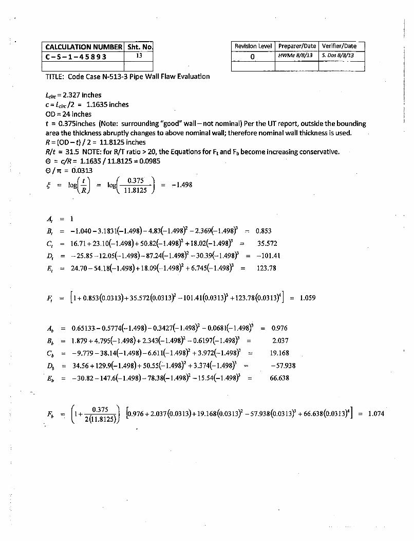
2) Determination of Load Relations Fm,, Fb, and F for through-wall flaws. For through-wall flaws, thecrack depth (a) will be replaced with the half crack length (c) in the stress intensity factor equationsused (per CC N-513-3 Appendix I, section I-1).
Circumferential Flaw Load Relations - From Reference 6 (NOTE: Ft =Fm)
Geometrical factor for axial load:
B, = [4 +{ CQ9 .)1 + DC0 + E,(0]
B, = -1.040 - 3.183 1(4) - 4.83()Y - 2.369(4ýY
C, = 16.71 + 23.10(,)+ 50.82(Y)2 + 18.02(ý)
D, = - 25.85 - 12.05(4) - 87.24(ýY - 30.39(Y)3
E, = 24.70 - 54.18(4) +18.09(Y)2 + 6.745(Y)3
l og( R
Geometrical factor for bending moment:
Fb= (I± [ Ab +±Bb(")D+CbQP-D + DbQ(±b"~
Ab = 0.65133- 0.5774(g)- 0.3427() 2 - 0.0681(4)
Bb = "1.879 + 4.795(ý) + 2.343(ý4Y - 0.6197(ýY
Cb = - 9.779 - 38.14(g) -6.61 1()2 + 3.972(•)3
Db = 34.56 + 129.9() + 50.55()2 + 3.374(43
Eb = -30.82-147.6(ý')--78.38(ý)Y -15.54('3
l log(•-
CALCULATION NUMBER Sht. No
C-S-1-45893 13
TITLE: Code Case N-513-3 Pipe Wall Flaw Evaluation
Revision Level Preparer/Date Verifier/Date0 HWMe 8/8/13 S. Das 8/8/13
Lc= 2.327 inches
c= Lrc,2 = 1.1635inchesOD = 24 inches
t = 0.375inches (Note: surrounding "good" wall - not nominal) Per the UT report, outside the boundingarea the thickness abruptly changes to above nominal wall; therefore nominal wall thickness is used.R = (OD - t) / 2 = 11.8125 inches
Rit = 31.5 NOTE: for R/T ratio > 20, the Equations for Ft and Fb become increasing conservative.0 = c/R = 1.1635 / 11.8125 = 0.09850 / T = 0.0313
CALCULATION NUMBER Sht. No] Revision Level Preparer/Date Verifier/Date
C-S-1-45893 14 0 HWMe 8/8/13 S. Dos 8/8/13
TITLE: Code Case N-513-3 Pipe Wall Flaw Evaluation
Axial Flaw Load Relation
F = 1 + 0.0724492A + 0.64856X2 - 0.2327,V + 0.03815424 - 0.0023487 X
where
c = half crack length
A = c/(Rt)X
Laxat= 1.5 inches
c = LaxaIl/2 = 0.750 inchesOD = 24 inchest = 0.375inches (Note: surrounding "good" wall - not nominal) Per the UT report, outside the boundingarea the thickness abruptly changes to above nominal wall; therefore nominal wall thickness is used.R = (OD - t) / 2 = 11.8125 inches
A = cl (Rt)'1 2 = 0.750 / (11.8125 x 0.375)1/2 = 0.356
F : 1+0.072449(0.356)+ 0.64856(0.356)2 -0.2327(0.356)3 + 0.038154(0.356)4 -0.0023487(0.356)'
= 1.098
CALCULATION NUMBER Sht. No.
C-S-1-45893 15
TITLE: Code Case N-513-3 Pipe Wall Flaw Evaluation
Revision Level Preparer/Date Verifier/Date
0 HWMe 8/8/13 S. Das 8/8/13
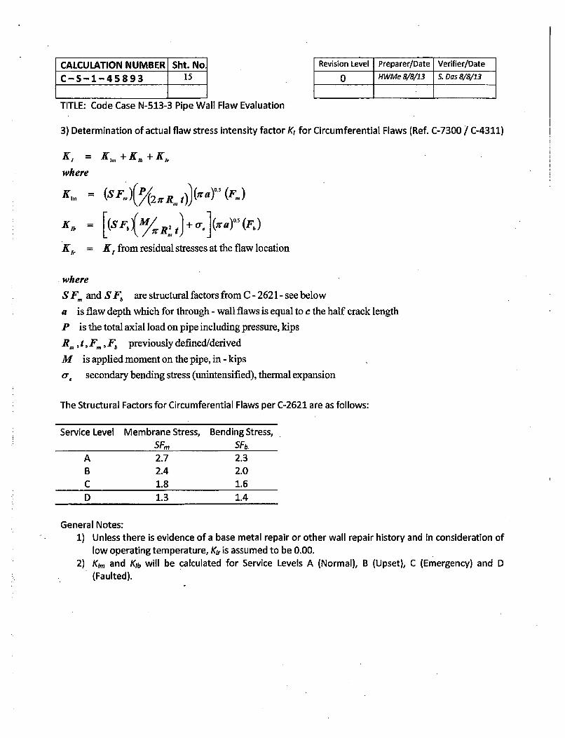
3) Determination of actual flaw stress intensity factor K, for Circumferential Flaws (Ref. C-7300 / C-4311)
K, = KI, + KA + Kir
where
K. = (SFn)(P 2 TrR at)a) (F.,)
K A = ( , M / '+ a,( z a) " (F ,)
Kir = K 1 from residual stresses at the flaw location
where
S F, and S Fb are structural factors from C -2621 - see below
a is flaw depth which for through - wall flaws is equal to c the half crack length
P is the total axial load on pipe including pressure, kips
R,,tFr,F, previously defined/derived
M is applied moment on the pipe, in -kips
a, secondary bending stress (unintensified), thermal expansion
The Structural Factors for Circumferential Flaws per C-2621 are as follows:
Service Level Membrane Stress, Bending Stress,SF, SFb
A 2.7 2.3B 2.4 2.0C 1.8 1.6D 1.3 1.4
General Notes:1) Unless there is evidence of a base metal repair or other wall repair history and in consideration of
low operating temperature, KI, is assumed to be 0.00.2) Kim and Kib will be calculated for Service Levels A (Normal), B (Upset), C (Emergency) and D
(Faulted).
CALCULATION NUMBER Sht. No]
C-S-1-45893 16
TITLE: Code Case N-513-3 Pipe Wall Flaw Evaluation
P and M determination for Service Levels A, B, C & D
Determination of actual flaw stress intensity factor K, for Circumferential Flaws
K, = K1++Kb+KIr
where
KI.= (SFn,)(P 2 7 .Rmt))(ra)°5 (Fm)
Kib [(SFb(M tJ+o.,J(Yrayo )
Kir = 0.0
The stress intensity attributed to residual stresses (Kir) is 0.0 based upon the fact that the piping at theleak location was replaced in April 2011 under EC# 156603. At the time of the replacement there was noevidence of a base metal repair nor was one applied. Furthermore this piping is subject to low operating
temperature.
CALCULATION NUMBER Sht. No] Rev
C-S-1-45893 18
TITLE: Code Case N-513-3 Pipe Wall Flaw Evaluation
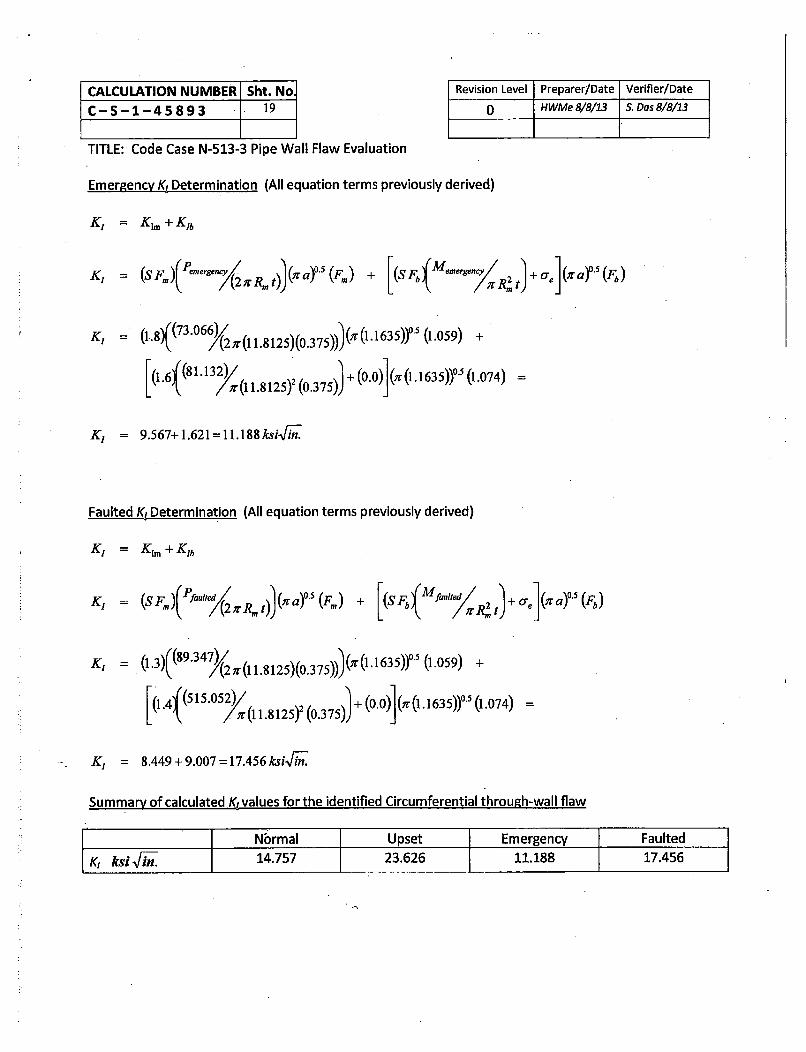
Normal K, Determination (All equation terms previously derived)
K, = K• + Kib
ision Level Preparer/Date Verifier/Date0 HWMe 8/8/13 S. Das 8/8/13 I
L Q 4{(515.052)/, i 82) o3 5I (0.0) (Ti .1 635))05 (1.074)-
K, = 8.449+9.007=17.456ksiVin.
Summary of calculated K, values for the identified Circumferential through-wall flaw
Nbrmal Upset Emergency Faulted
K, ksi Fi. 14.757 23.626 11.188 17.456
CALCULATION NUMBER Sht. No,
C-S-1-45893 20
TITLE: Code Case N-513-3 Pipe Wall Flaw Evaluation
Revision Level Preparer/Date Verifier/Date
0 HWMe 8/8/13 S. Das 8/8/13
4) Determination of actual flaw stress intensity factor K, for Axial Flaws (Ref. C-7400 / C-4312)"
K, = KI + Ki,
where
Kj,= (SFm)(jpRm/t)(;r a/Q)°* (F)
Kl,. = K, from residual stresses at the flaw location
where
F is the structural factor from C - 2622- see below
a is flaw depth which for through - wall flaws is equal to c the half crack lengthp is the maximum operating pressure, ksi
SFm,&R,t previously defined/derived
Q = I + 4.593 (ally"65 = 1.0 (set to unity per CC N -513 -3 Appendix I for through - wall flaws)
The Structural Factor for Axial Flaws per C-2622 are as follows:
Service Level Membrane Stress,SFm
A 2.7B 2.4C 1.8D 1.3
General Notes:3) Unless there is evidence of a base metal repair or other wall repair history and in consideration of
low operating temperature, K1, is assumed to be 0.00.4) Kim will be calculated for Service Levels A (Normal), B (Upset), C (Emergency) and D (Faulted).
Determination of actual flaw stress intensity factor K, for Axial Flaws
CALCULATION NUMBER Sht. NolC-S-1-45893 21
Revison0I
Level Preparer/Date Verifier/Date
HWMe 8/8/13 S. Das 8/8/13
TITLE: Code Case N-513-3 Pipe Wall Flaw Evaluation
Determination of actual flaw stress intensity factor K, for Axial Flaws
K, = Ki + K,
where
K, = (SFmXpJm/t)( Ta/1.00 5 (F)
Ki, = 0.0
The stress intensity attributed to residual stresses (Kir) is 0.0 based upon the fact that the piping at theleak location was replaced in April 2011 under EC# 156603. At the time of the replacement there was noevidence of a base metal repair nor was one applied. Furthermore this piping is subject to low operatingtemperature
Normal Kj Determination (All equation terms previously derived)
The calculated Stress Intensity Factors include the required structural factors prescribed by Code Case N-513-3 and ASME Section XI, Division 1 Article C-2620. The acceptable calculated stress intensity factorsensures the acceptability of the pipe for temporary service.
The Structural Factors for Circumferential Flaws per C-2621 are as follows:
The Structural Factor for Axial Flaws per C-2622 are as follows:
Service Level Membrane Stress,SFm
A 2.7B 2.4C 1.8D 1.3
A review of the Flaw UT data identified an adjacent minimum remaining pipe wall (tp) of 0.388 inch. This isa non-planar flaw and per CC N-513-3 must be greater than the N-513-3 derived minimum wall.
t, = (0.388)->tm. = (0.120)(calculatedon sht.9)
CALCULATION NUMBER Sht. No,
C-S-1-45893 24
TITLE: Code Case N-513-3 Pipe Wall Flaw Evaluation
4.0 ASME Code Required Minimum Wall Thickness per CC-597
Determine minimum wall required for Design Pressure
Revision Level Preparer/Date Verifier/Date0 HWMe 818113 S. Das 818113
_i PD.S2(S+yP)
P = Design operating pressure at flaw location = 150 psiRef. Source = Calculation 4.4.17.04F-CALC Rev. 6, Sht. U-3D, = Piping outside diameter = 24 inchesS = pipe material allowable stress at Design Temperature = 17100 psi @2000 Fy = 0.4, except where D, < 6 (tmi) (Note: use 0.4 then verify that this value is acceptable)
(150)(24) 0.105 inch
2(17100+ 0.4(150)) =
Do = 24 < 6(0.105) = 0.630 use of 0.4 is acceptable
Determine minimum wall required for mechanical loading
The effect on piping stresses at the reduced wall location must be evaluated with consideration givento changes in the pipe metal area, pipe inside area, section modulus and stress intensification factor.
] Simplified stress evaluation is acceptable with calculated stresses within Code allowable. Check
for cyclic operation.
-- Simplified stress evaluation is not acceptable. Detailed review performed in calculation
Evaluation for Cyclic Operation
IS t pred = 0.105 > 0.75 t norm = 0.281 ? DYES E NO
Is N (Equivalent Full Temperature Cycles) at time of next inspection < 150 ? H YES E NO
If the response to both questions is YES, piping stress equations that include thermal expansion and anchormovements stresses need not be evaluated. If not, continue below.
The thermal expansion and anchor movement stress at the inspection location from the referenced analysisof record is not applicable (cold system; no anchor movement).
The Stress Range Reduction Factor (f) used in analysis is 1.0
Is N (Equivalent Full Temperature Cycles) < 650 ? E YES DI NO
If the response is YES - no further cyclic evaluation is required; component is acceptable.
CALCULATION NUMBER Sht. No
C-S-1-45893 26
TITLE: Code Case N-513-3 Pipe Wall Flaw Evaluation
Revision Level Preparer/Date Verifier/Date
0 HWMe 8/8/13 S. Das 8/8/13
7.0 REVIEWERS COMMENTS AND RESOLUTIONS
Line by line check performed.
Any and all reviewer comments, corrections, and changes have been reviewed by the Cognizant DesignEngineer and have, with the mutual consent of the reviewer, been incorporated.
8.0 ATTACHMENTS
Check as applicable; identify Attachment letter and number of sheets:
ED Pending Engineering Change Review - Attachment _ Number of sheets
-- ADLPIPE / CARS output.
Input file Output file Run date Attachment Number of sheets
Input files stored on EMAGDK#
I• Other: (list along with Attachment letter and number of sheets per attachment).
Identified Flaw UT Report Attachment A Number of Sheets: 7
Total number of Attachment sheets: 7.
Form A: Ultrasonic Thickness Examination Report
COMPONENT ID: [ -
DRAW•iNG NO.: k-ri-L4
WORK DOCUMENT:
SYSTEM:REV.:
.BLDG.:
____ CLASS: _____
_ _ _ JOINT #: YL sziuL,
P'k-& ROOM: SLbr ELEV.: C---I
INSTRUMENT DATAINSTRUMENT: MFG/MODEL:
'law Detector 0 Thickness Gaug
COMP SURFACE TEMP >1250 1P
_ZE' /Sz&zcz/
0y 0 YES FLS No.: 9/22CAL. DUE DATE:
THICKNESS: O.• 01 -• ___ " TRANSDUCER
CAL BLOCK FLS NO.: TIME MFG.: mc-VO.1•
MATLCS_ CAL. DUE: CHECKED SER #: t
INrrIAL: S.IZ)E O.1,t -P -- s tzE.."I:Lr FREQ: MHZ
UT Thickness Examination at Through Wall Leak Upstream of SW-V-65
(817113, WO-40260904-02, AR-01 895334)
Discussion
On August 7, 2013 a through wall leak was detected on line SW- 802-004-153-24" upstream of SW-V-65. The leak is adjacent to the Tee-to-Pipe weld near SW-V-104. In accordance with WO-40260904-02the area surrounding the through wall leak was UT examined. Additionally, in accordance with AMSECode Case N-513 the entire circumference at the through wall leak was also examined. Approximatelysix inches upstream and downstream of the through wall leak area was examined (see below). Theexam was performed to determine magnitude and extent of all flaws the pipe section.
Examination Technique
The examination was performed using a 12 element, 5MHz array with a 7.2 mm active aperture. Thefocal laws generated 61 Longitudinal Wave (L-Wave) examination angles from -30° to 300.
In addition to the L-Wave exam a supplemental Shear Wave (S-Wave) angle beam exam wasperformed. This exam was performed in order to eliminate the possibility that a non-corrosion typedegradation mechanism, specifically planar flaws or cracking, was present. This technique used thesame array but generated only 41 angles that ranged from 300 to 700.
Examination Results
The examination revealed that the through wall leak at this location is the result of a single isolated flawthat appears to be related to corrosion. The thickness ranges of the examination areas away from theflawed area at the through wall leak are within the nominal with no corrosion present. The thicknessranges outside the leak region were 0.592"-0.896" for the Tee and 0.388"-0.420" on the piping.
WO-40260904-02, UT Report SummaryIT !(Ct
Page 1 of 5
NExTeraENEHRQY1 4
,ii"O SEABROOK
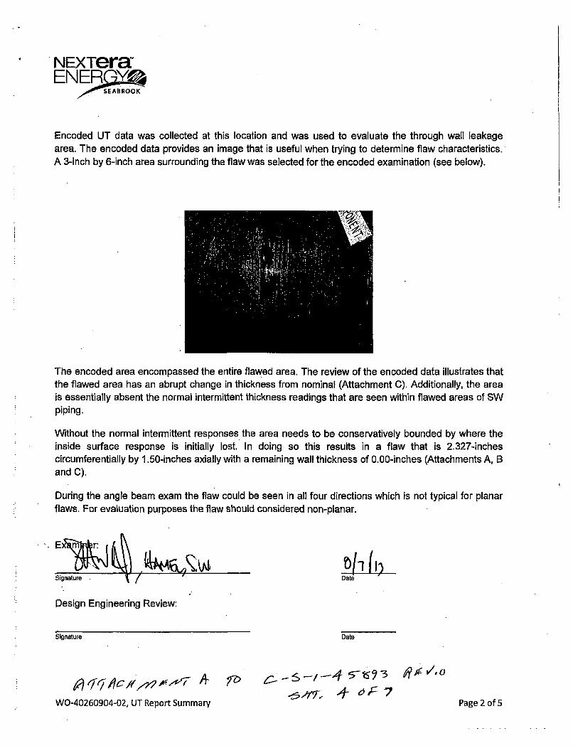
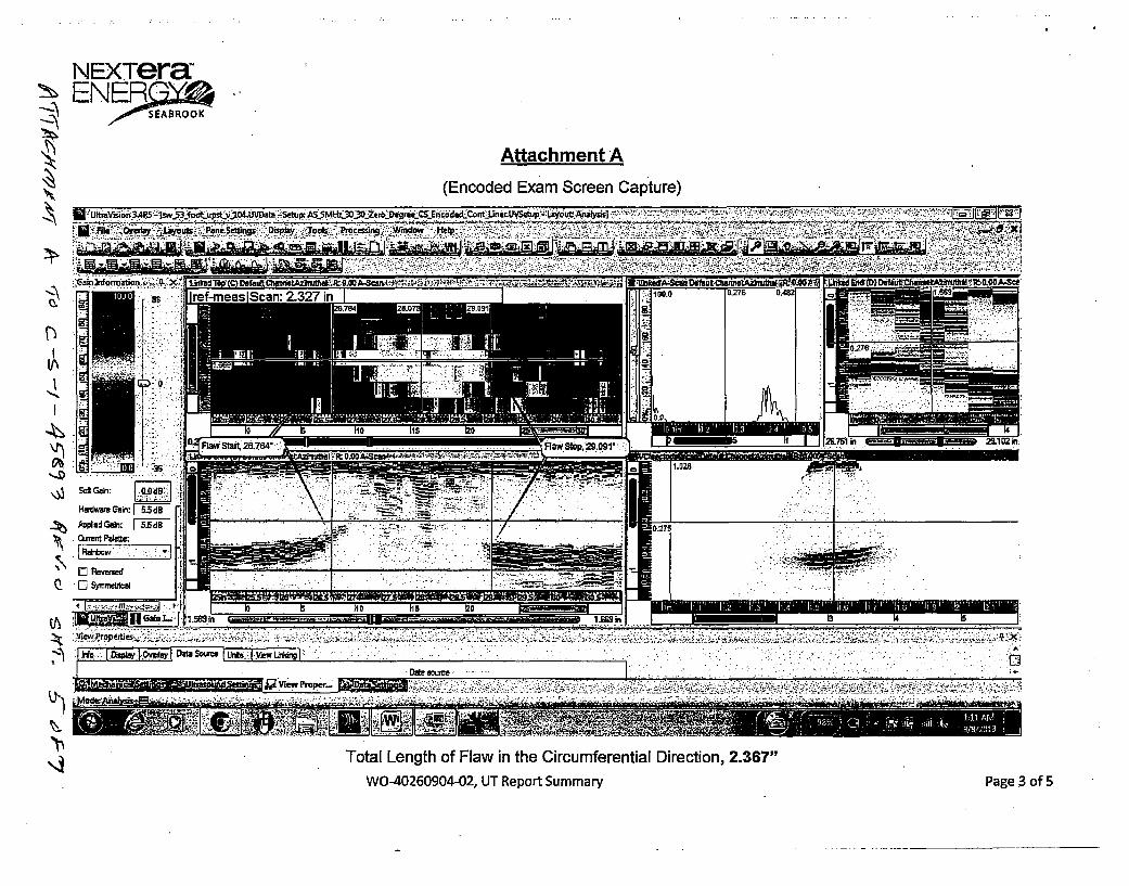
Encoded UT data was collected at this location and was used to evaluate the through wall leakagearea. The encoded data provides an image that is useful when trying to determine flaw characteristics.A 3-inch by 6-inch area surrounding the flaw was selected for the encoded examination (see below).
The encoded area encompassed the entire flawed area. The review of the encoded data illustrates thatthe flawed area has an abrupt change in thickness from nominal (Attachment C). Additionally, the areais essentially absent the normal intermittent thickness readings that are seen within flawed areas of SWpiping.
Without the normal intermittent responses the area needs to be conservatively bounded by where theinside surface response is initially lost. In doing so this results in a flaw that is 2.327-inchescircumferentially by 1.50-inches axially with a remaining wall thickness of 0.00-inches (Attachments A, Band C).
During the angle beam exam the flaw could be seen in all four directions which is not typical for planarflaws. For evaluation purposes the flaw should considered non-planar.