Sealing Concrete and Steel Grain Storage Oklahoma Grain Elevator Workshops - - - Ronald T. Noyes, Ph.D, P.E. Extension Agricultural Engineer Biosystems & Agricultural Engineering Dept. Oklahoma State University Besides keeping grain dry, grain storages should be well sealed for two other basic reasons: (1) To minimize grain insect entry problems into base and sidewall grain, and (2) to minimize leakage losses of phosphine or other fumigants during fumigation. Besides improved insect kill (efficacy), tighter sealed structures require lower dosage rates, which reduces the cost of future fumigations and paying for the sealing materials and labor. When clean grain is transferred into a clean, sanitized structure with base and sidewalls well sealed, the main insect infestation and population growth should be on the grain surface in the structure headspace. Permanently sealing all non-functional base, sidewall and roof openings is the first priority of sealing storages. The second sealing priority is to seal functional openings at all times during the year when the component is not being used. In addition to being potential moisture entry and fumigant gas leakage points, openings of any size in grain storage silo, bin or building bases, sidewalls and roofs are major access points for grain insect entry. Thus, one of the most beneficial, cost effective projects that a grain elevator manager can do is to permanently seal non-essential grain storage structure openings, and semi-permanently seal all other functional openings to the structure except roof vent sources of air ingress/egress to the headspace, such as roof vents on bins, silos and flat storage and grain fill doors on silos. Permanent Sealing of Non-essential Structural Openings Primary sealing points of non-essential structural openings are: • exterior under-roof vents in concrete silos; • steel bin roof eave gaps . • silo roof deck-to-wall gaps Concrete annex and head house silos sometimes have irregular width gaps between the roof deck and the top of outside silo walls that need to be sealed. Exterior walls should be inspected from inside the silos during bright sunny days to see if light shows any where along the top of the silo outer wall, except at rectangular exterior vents. Less obvious access openings/leak points in steel buildings that should be permanently sealed: • clearance openings around centrifugal direct drive motor shafts, • bolts missing from bolt holes,
Transcript
Sealing Concrete and Steel Grain Storage Oklahoma Grain Elevator Workshops
Oklahoma State University Besides keeping grain dry, grain storages should be well sealed for two other basic reasons: (1) To minimize grain insect entry problems into base and sidewall grain, and (2) to minimize leakage losses of phosphine or other fumigants during fumigation. Besides improved insect kill (efficacy), tighter sealed structures require lower dosage rates, which reduces the cost of future fumigations and paying for the sealing materials and labor. When clean grain is transferred into a clean, sanitized structure with base and sidewalls well sealed, the main insect infestation and population growth should be on the grain surface in the structure headspace. Permanently sealing all non-functional base, sidewall and roof openings is the first priority of sealing storages. The second sealing priority is to seal functional openings at all times during the year when the component is not being used. In addition to being potential moisture entry and fumigant gas leakage points, openings of any size in grain storage silo, bin or building bases, sidewalls and roofs are major access points for grain insect entry. Thus, one of the most beneficial, cost effective projects that a grain elevator manager can do is to permanently seal non-essential grain storage structure openings, and semi-permanently seal all other functional openings to the structure except roof vent sources of air ingress/egress to the headspace, such as roof vents on bins, silos and flat storage and grain fill doors on silos. Permanent Sealing of Non-essential Structural Openings Primary sealing points of non-essential structural openings are:
• exterior under-roof vents in concrete silos; • steel bin roof eave gaps. • silo roof deck-to-wall gaps
Concrete annex and head house silos sometimes have irregular width gaps between the roof deck and the top of outside silo walls that need to be sealed. Exterior walls should be inspected from inside the silos during bright sunny days to see if light shows any where along the top of the silo outer wall, except at rectangular exterior vents. Less obvious access openings/leak points in steel buildings that should be permanently sealed:
• clearance openings around centrifugal direct drive motor shafts, • bolts missing from bolt holes,
• gaps between flanges on aeration fans connected to transition ducts, • aeration duct entrance through the bin wall or concrete foundation at the base.
Semi-permanent Sealing of Functional Openings The second level of sealing involves sealing functional equipment and openings that are used on a limited basis during the year. Examples of equipment/limited-use openings to be sealed:
• discharge spouts or conveyors (conveyor outlets connected to other conveyors), • gravity fill downspouts from elevator legs/distributors • sidewall doors on steel bins and flat storages, • gable end-wall fans and louvers in flat storage end gable walls, • push/pull rod discharge slide gate controls on steel bins and flat storages, • concrete silo fill doors and manhole covers
Temporary Sealing for Fumigation To maintain healthy grain, all grain storage headspaces should be ventilated -- have fresh air access during the entire storage period up to the time of fumigation. For steel bins, the only roof venting this should be through roof vents. Flat storages should have roof vents and gable fan and louvers free to operate. Concrete silo headspace ventilation usually be provided by surface roof vents or by fresh air movement provided through air gaps around manhole covers or closed grain inlet doors caused by temperature and barometric pressure changes. Grain should be visually inspected at least bi-weekly during the storage season, so bin roof entry doors or hatches should remain unsealed until time to fumigate. Thus, with a properly sealed storage, the only sealing at the time of fumigation should be roof entry hatches and vents on steel bins. Flat storages should have roof vents and gable venting systems sealed in addition to side and gable fill conveyor entry doors. The only additional sealing at the time of fumigation for concrete silos should be grain fill or man-entry hatches on the roof deck. However, if downspouts to bins or silos have not previously been sealed, they should be sealed just before each fumigation. Sealing Materials -- The Tools of Sealing The starting point to sealing all storage openings is to have the correct sealing materials. Primary bulk grain storage sealing tools are listed below with brand names listed where specific materials are recommended. Otherwise, generic materials available at a wide range of building supply companies can be used. Figure 1 shows a selection of primary sealing materials used at OSU for sealing silos and steel bins. A partial list of sealing materials, not listed in any priority or sequence, are:
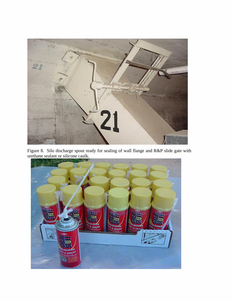
• Great Stuff (or similar product) -- pressurized expandable closed-cell foam (Great Stuff manufactured by Flexible Foam, Inc., Joliet, IL -- supplied by Walmart, Lowes, Home Depot, lumber yards, commercial and home building supply stores and other outlets). Make sure you buy closed-cell foam, to decrease fumigant movement.
• Rubberflex Bin Seal -- concrete silo repair and bin seal kit (bin bases) with gray or white acrylic based elastomeric coating applied over 6 inch wide polyester screed cloth material. Polyester cloth is extremely strong. Pliable elastomeric coating and polyester cloth material sets up and stays flexible in wide range of temperatures, with 400% or more elongation/contraction, stretching and compressing as bin foundation ring moves. Product manufactured by Republic Coatings (Marketed by Specialized Coatings, Inc., P.O. Box 642 Atwood, IL 61913; Ph. 217-578-2986).
• Durathane Sealant -- urethane caulking compound. Has high adhesion but remains flexible for life of product (guaranteed 10 years). Urethane remains more pliable with age than silicone and has better resistance to phosphine gas penetration (Durathane still flexible after 15-16 years). Product manufactured by Republic Coatings (Available from Specialized Coatings, Inc., P.O. Box 642 Atwood, IL 61913; Ph. 217-578-2986).
• Ultra high reflectivity white elastomeric roof coating (Kool Seal or similar product--supplied by Lowes, Home Depot, and many lumber yards, commercial and home building supply stores and other outlets); Use 4- to 6-inch wide polyester mesh screed with Kool Seal elastomeric roof coating to reinforce and seal gaps between concrete and steel.
• Kool Seal white acrylic patching cement (in caulking tube), a flexible acrylic cement for sealing seams, holes, and gaps.
• GE -- high quality silicone caulking compound for outdoor use (Opaque or colored material preferred to block light). GE has a high quality outdoor silicone caulk with a rating score of 7 (maximum) in all rating categories.
• Camie 363 -- high strength fast tack pressurized contact spray adhesives - - (available from Industrial Fumigant Company (IFC), Olathe, KS; 3M has similar spray adhesive products)
• Camie 300 -- general purpose spray adhesive -- (available from Industrial Fumigant Company (IFC), Olathe, KS; 3M has similar spray adhesive products).
• Plastic sheeting -- 6 mil polyethylene sheeting in 10 to 20 ft widths and variable lengths up to 100 ft -- available from most building supply outlets.
• Tough plastic bags -- heavy duty 35 to 55 gallon trash bag liners of 4 mil plastic -- available from home and building supply outlets.
• High quality duct tape or heating and air conditioning tape -- 2-inch and 3-inch width; price is usually a good indicator on this product. Top of the line is recommended here for use in long term outside weather conditions.
• High quality brown/tan paper fumigation sealing tape -- a strong tape with excellent adhesive quality with better resistance to phosphine gas passage than duct tape. Available from IFC, other fumigation suppliers and elevator equipment outlets.
• Fine wire mesh duct screen -- 30 mesh to 50 mesh -- tape over roof vent inlet openings as insect barrier seals (pressure aeration systems only).
Concrete Silo Sealing
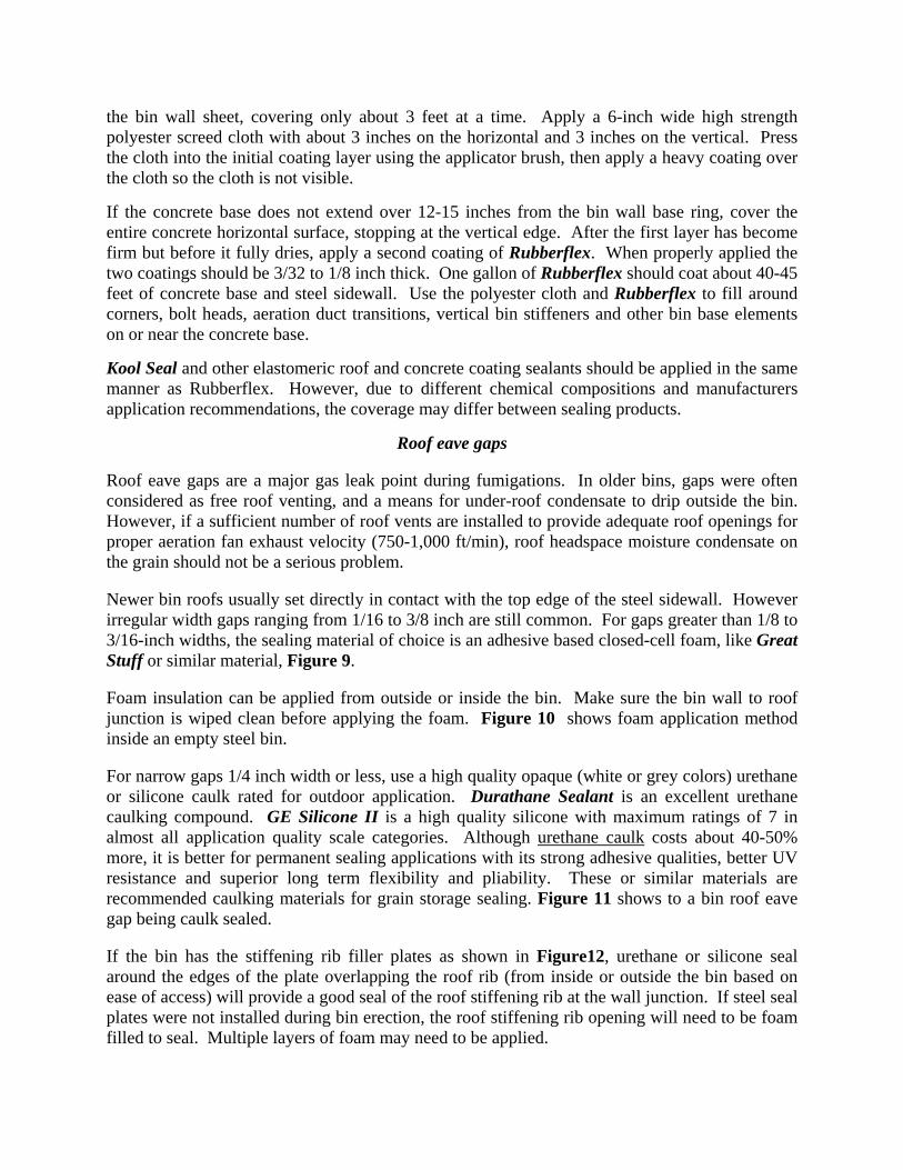
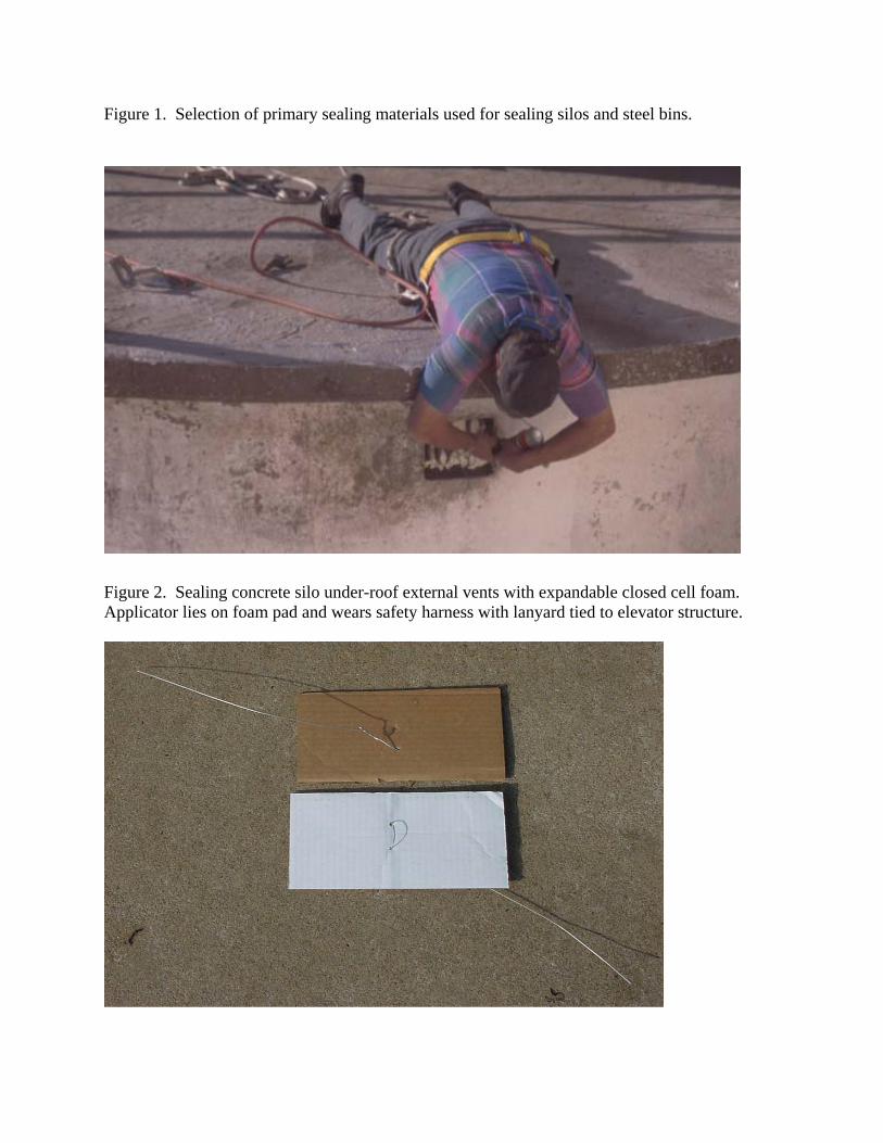
Exterior under-roof vents The primary silo sealing problem in concrete silos are exterior under-roof vents. Sealing these rectangular openings containing vertical steel or cast-iron bars can be done from the outside by using a safety harness, laying on a pad with harness lanyard firmly anchored to the elevator structure, and reaching over the roof edge to apply Great Stuff (or other suitable closed cell
expandable foam), Figure 2. An alternative is to seal the vents from the grain surface inside the silos. The vents should be cleaned with a pressure air nozzle, broom or brush before sealing to minimize leaks where dirt is blown out under or above the foam by air pressure inside the silo. With either method, a backer board should be used on the opposite side of the re-bars from the side that the spray foam is applied. Cardboard cut about 1-inch smaller in each dimension than the rectangular opening (use a 7 x 9-inch cardboard panel for an 8 x 10-inch vent) works well as there is often small chunks of cement mortar or dirt buildup that makes the openings irregular in shape. A 12-inch piece of stiff wire is looped through two 1/8-inch holes punched 1-inch apart at the center of the cardboard, Figure 3. The short end is twisted around the remaining 10-inch longer wire end to provide a loose loop through the cardboard and a pivotal handle to push the cardboard between the two center bars, then turn it flat and pull it up behind the bars. This cardboard backstop reduces by half or more the foam volume needed to seal each vent and keeps foam from falling into the silo. In Figure 4, the millwright is positioned and equipped to seal a silo external under-roof vent with cardboard foam stop panel and supply of foam containers. In Figure 5, the vent is partially filled with foam, with the retainer wire "handle" to the cardboard foam backstop visible. The wire can be left hanging through the foam or can be wrapped around a steel bar. With the cardboard block about 1 inch behind the bars, one can of Great Stuff can do 1.5 to 2 exterior 8 x 10-inch vents. Once the gaps between the re-bars has been filled, the foam should be applied in two to three layers in front of the bars to allow each layer to expand and harden before the next "lift" is added. A 5-inch or 6-inch pickup or truck mirror with mounting arm attached, Figure 6, with a small rope lanyard connecting the mirror to the safety harness to keep it from falling, is a good way to apply the foam, or to check for holes that need to be foam filled along the top of the vent. Figure 7 shows a sealed under-roof vent after complete foam fill has been applied. Another method that makes the foam application easier is to use a 1/8 to 3/16 inch ID "extension" tube of about 4 to 6 feet in length so the applicator does not have to hold and operate the can. A short length of 3/16inch "Tygon" rubber tubing provides a flexible connector between a less flexible length of 1/8-inch ID tubing. A second person with a supply of cans can release the foam while the applicator guides the foam into place using the long flex tubing. An alternative method of sealing vents is to fill the opening with a close fitting plywood or steel plate with a "J-bolt" and wing nut assembly through a hole in or near the center of the plate (depending on the positioning of the vertical steel or cast-iron bars). This plate could be pushed into the opening from the outside so the J-bolt is hooked around a vertical steel bar near the center, then the panel can be pulled tight against the vertical bars with the wing nut. This should be close to a "press-fit" if the rectangular vent openings are of uniform dimensions. For an 8 x 10-inch vent, using a 7.75 x 9.75-inch exterior grade or marine grade plywood board will leave a 1/8 inch gap on all sides of the panel. Apply a urethane sealant caulk around the edges of the opening as shown in Figure 6 and check caulking seal along the top of the plate by using a truck mirror. A small extension tube attached to the silicone tube nozzle using Tygon tubing can also be used to apply the silicon around the seal plate border gap. If a silicone gun is used by the person sealing, use a small rope lanyard attached between the caulking gun and the safety harness to prevent dropping the caulking gun.
If the under-roof vent sizes are consistent, a slight variation of the above method would be to develop a "press-fit" board of marine grade plywood or steel plate that will just fit the opening and can be tapped into place against the steel re-bar. A single bolt can be placed through the middle of the board or plate as a "handle". Test the fit of the board/plate, then coat the edges of the board or plate with urethane caulk, and push it into place against the steel bars. Then run a filet of urethane caulk bead around the plate to concrete junction. With clean concrete, the urethane will adhere to the concrete and plywood or steel, locking it in place permanently. Another alternative vent sealing method would be to fill the opening with expandable cement mortar, but this may require a millwright working from a boatswains chair on a safety system cable or rope system over the side of the elevator, or from the grain surface inside the silos. If the person applying the cement mortar works from the grain surface inside the silos, and a backer board can be wired to the outside face of the concrete silo, covering the vent, then the mortar can more easily be applied by just filling the box and smoothing up the interior face of vent flush with the inside silo wall. Two plywood work platform boards cut to fit into the silos can provide a grain surface platform for the operator to stand on with the other board used as the mortar mix platform or the foam supply operator platform (use the buddy system when working inside silos) can make the work easier when sealing from inside. Each board should have a rope attached for easy movement of the board in and out of the silos.
Concrete silo discharge spouts in basement or conveyor tunnel Discharge spouts in basement tunnels are relatively easy to seal. Two areas of sealing are involved: (1) the flange where the rectangular spouts passes through the concrete tunnel wall or roof, and (2) the rack and pinion (R&P) slide gate, Figure 8. The spout wall flange is an area that requires permanent sealing as this will definitely be a phosphine gas leak point. Thorough cleaning is mandatory. Use soapy water, then rinse water to wash the concrete wall and the flanges and let dry. After the flange area is thoroughly cleaned, apply a urethane caulk seal bead around the edges of the flange plate to provide a continuous seal between steel flange and concrete wall completely around the flange. The area that needs the most attention is against the wall under the sloped spouts from the main silos. Take a good trouble light (with rough duty safety bulb) or portable lantern that will provide plenty of light under the spout. The urethane caulk seal must be well-bonded between steel and concrete as phosphine gas is under pressure inside the discharge duct as the gas is forced upwards through the silo. The R&P slide gate needs to be sealed throughout the year as a functional piece of equipment until needed. Be sure the R&P slide gate is fully seated before sealing the slot in the housing that the slide gate goes through. Use urethane caulk across both sides of the plate where it slides through the flange slot across the top or side of the spout and around the R&P track. Since this is a semi-permanent seal, use a relatively small bead of urethane caulk on this application as it has much higher adhesion than silicone and may be more difficult to break loose. Both sides of the flange (open between the flange plates in many elevators) should be permanently sealed. . If the flange slide plate has open sides, force urethane caulk 1/4 to 3/8-inch down into the space between the flange plates which the slide plate slides against so the
edges of the slide plate flange housing is completely sealed. Check the depth from the open edge of the flange to the edge of the slide plate. Urethane caulk should not be in contact against the edge of the slide plate, or it may "weld" it in place. There should be sufficient gear ratio to open and close the slide gate so the urethane caulk seal against the face of the place can be broken. One or two R&P slide gates could be tested using urethane caulk for all sealing to see how difficult it is to open the slide gate after it has been sealed for two or three weeks. If it is not difficult, then use urethane caulk on all gates. If reopening the slide gate is a problem, use silicone across both faces of the plate. After the seal has been disrupted from the previous fumigation, it may be necessary to reseal along both sides of the plate where it slides into the spout. Make sure the slide plate is seated hard against the bottom or side of the spout when the gate is closed, before sealing to minimize gas leakage around the end of the slide plate. A third area in the discharge tunnel that might be sealed is the outlet of the spout, but this is often covered by a dust control suction air hood over the belt in older belt unload conveyor systems. If there are no dust hoods, or if dust hoods are easily removed, then the spout should be double plastic bag sealed to contain gas that may slip past the end of the R&P slide gate end seat inside the discharge spout. If the discharge conveyor is a drag conveyor, the inclined and vertical silo discharge spouts will be connected through the top of the drag conveyor housing. Drag conveyors are usually fairly well sealed for dust containment, but they should be rechecked for sealing at dust leak points or where it appears that gas might leak out at flanges. Seal as needed.
Headhouse silo discharge spout slide gates Although headhouse silo R&P slide gates are similar to annex silo gates, headhouse designs vary widely. Some newer headhouse designs use rectangular discharge spouts, but round spouts were quite often used for fill and discharge spouts in older elevators. R&P slide gates on round spouts may be somewhat different than nearby annex slide gates in the same elevator complex because the headhouse was built first. The annex was quite likely designed and built 10-20 years later by different companies. Headhouse designers often placed the R&P slide gate very close to or right against the concrete basement wall, making sealing more difficult. Sometimes the slide gates are inside walls. In those cases, the addition of a new slide gate for fumigation sealing may have to be added in the pipe outside the wall. Usually, the same methods of sealing headhouse silos should be used as described above for annex silo discharge slide gates. Steel Bin Sealing
Steel sidewall to base joints A good starting point on steel bins is to seal the wall base to concrete joint to prevent water and insect entry, Figure 9. A recommended sealing material is Rubberflex Bin Seal, an acrylic based elastomeric roof and concrete sealant. This relatively thick coating material should be applied in two relatively thick layers. After the foundation and steel is clean and dry, apply an initial light to moderate coating of Rubberflex to the concrete foundation and about 4 inches up
the bin wall sheet, covering only about 3 feet at a time. Apply a 6-inch wide high strength polyester screed cloth with about 3 inches on the horizontal and 3 inches on the vertical. Press the cloth into the initial coating layer using the applicator brush, then apply a heavy coating over the cloth so the cloth is not visible. If the concrete base does not extend over 12-15 inches from the bin wall base ring, cover the entire concrete horizontal surface, stopping at the vertical edge. After the first layer has become firm but before it fully dries, apply a second coating of Rubberflex. When properly applied the two coatings should be 3/32 to 1/8 inch thick. One gallon of Rubberflex should coat about 40-45 feet of concrete base and steel sidewall. Use the polyester cloth and Rubberflex to fill around corners, bolt heads, aeration duct transitions, vertical bin stiffeners and other bin base elements on or near the concrete base. Kool Seal and other elastomeric roof and concrete coating sealants should be applied in the same manner as Rubberflex. However, due to different chemical compositions and manufacturers application recommendations, the coverage may differ between sealing products.
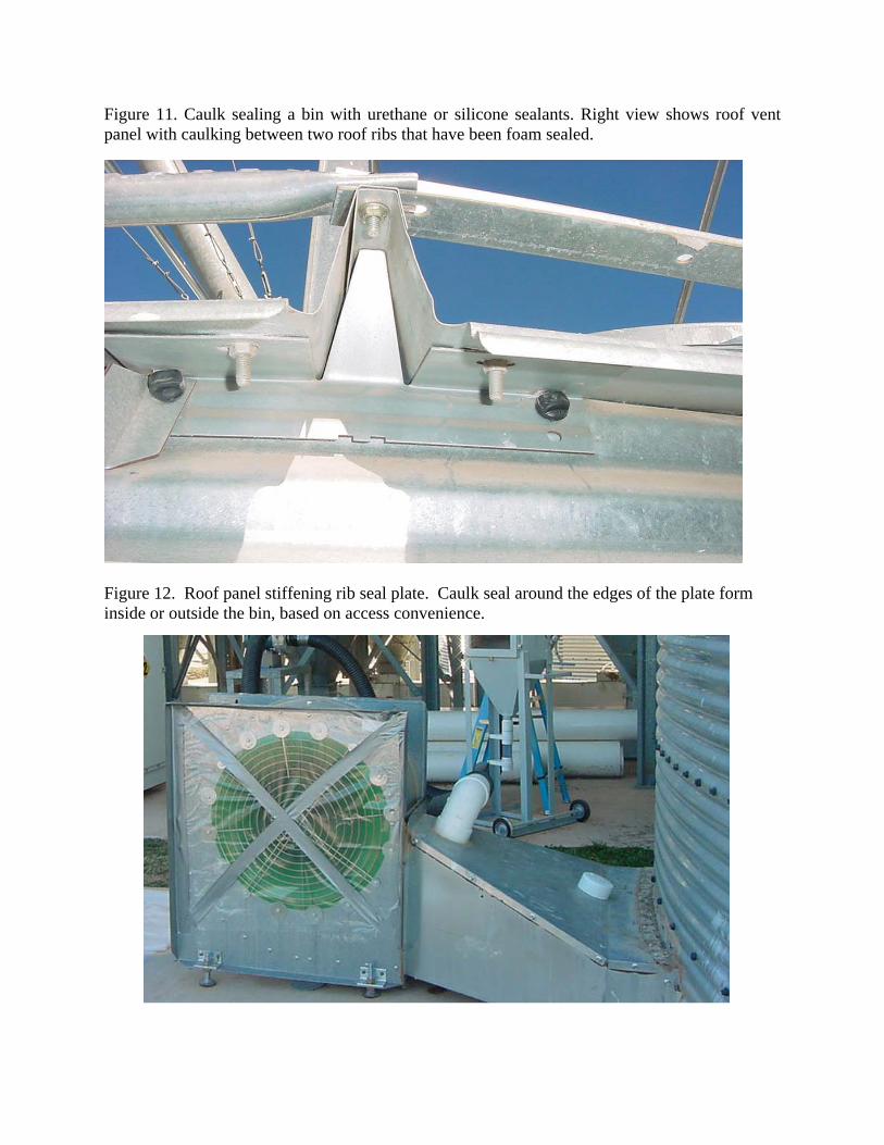
Roof eave gaps Roof eave gaps are a major gas leak point during fumigations. In older bins, gaps were often considered as free roof venting, and a means for under-roof condensate to drip outside the bin. However, if a sufficient number of roof vents are installed to provide adequate roof openings for proper aeration fan exhaust velocity (750-1,000 ft/min), roof headspace moisture condensate on the grain should not be a serious problem. Newer bin roofs usually set directly in contact with the top edge of the steel sidewall. However irregular width gaps ranging from 1/16 to 3/8 inch are still common. For gaps greater than 1/8 to 3/16-inch widths, the sealing material of choice is an adhesive based closed-cell foam, like Great Stuff or similar material, Figure 9. Foam insulation can be applied from outside or inside the bin. Make sure the bin wall to roof junction is wiped clean before applying the foam. Figure 10 shows foam application method inside an empty steel bin. For narrow gaps 1/4 inch width or less, use a high quality opaque (white or grey colors) urethane or silicone caulk rated for outdoor application. Durathane Sealant is an excellent urethane caulking compound. GE Silicone II is a high quality silicone with maximum ratings of 7 in almost all application quality scale categories. Although urethane caulk costs about 40-50% more, it is better for permanent sealing applications with its strong adhesive qualities, better UV resistance and superior long term flexibility and pliability. These or similar materials are recommended caulking materials for grain storage sealing. Figure 11 shows to a bin roof eave gap being caulk sealed. If the bin has the stiffening rib filler plates as shown in Figure12, urethane or silicone seal around the edges of the plate overlapping the roof rib (from inside or outside the bin based on ease of access) will provide a good seal of the roof stiffening rib at the wall junction. If steel seal plates were not installed during bin erection, the roof stiffening rib opening will need to be foam filled to seal. Multiple layers of foam may need to be applied.
A third method of sealing roof eave gaps on clean galvanized steel is to apply a high strength adhesive spray such as Camie 363 in a 2-inch band along the top of the wall and another 2-inch band along the lower roof surface right above the junction as a base layer, then apply 3-inch wide fumigation tape across the angle joint with approximately equal tape contact on sidewall and roof. The adhesive/tape seal should provide a long lasting tight seal across the roof gap except for the roof section stiffening ribs, which will need to be foam filled.
Screening Roof Vents for Insect Barrier OSU plans to conduct research on new vent inlet screen designs to retrofit or adapt to fit goose neck and mushroom style vents currently used on most steel grain bins in Oklahoma. This will involve using one or two separate fine mesh cloth screens (1-2-inches apart) of 30x30 to 50x50 wire mesh. Research concerns are restrictions to airflow, exposure to freezing rain, and determining largest mesh opening size in a design that will exclude all life stages of insects. This may require that the screen panel be spring loaded so it opens with aeration fan operation, but seals against gaskets when airflow stops. More will be reported as the barrier screen laboratory and field research work proceeds.
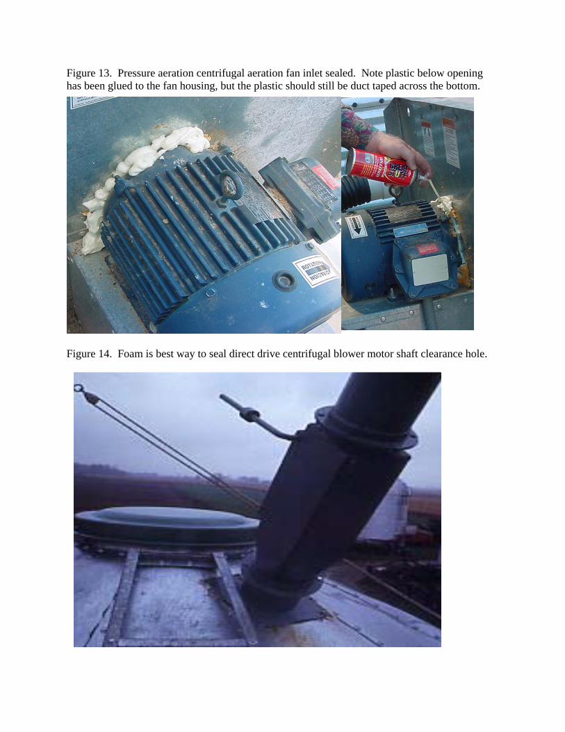
Sealing aeration fans The major reason for sealing aeration fans year-round is to exclude insects from entering the grain bin base. All fan openings should be sealed completely and left sealed until time to operate the aeration fans to cool the grain in the fall. Sealing aeration fans involves sealing the fan inlet or discharge, as well as any other fan housing or junction openings. Figure 13 shows the fan inlet sealing for a centrifugal fan set up for pressure aeration. The fan shown in this figure still needs the bottom of the plastic sheet duct taped to the fan housing for proper sealing. Direct drive centrifugal fans have a clearance opening through the blower sidewall around the motor shaft that must be sealed. Figure 14 shows the shaft being sealed by foam filling the space between the motor end plate and fan housing.
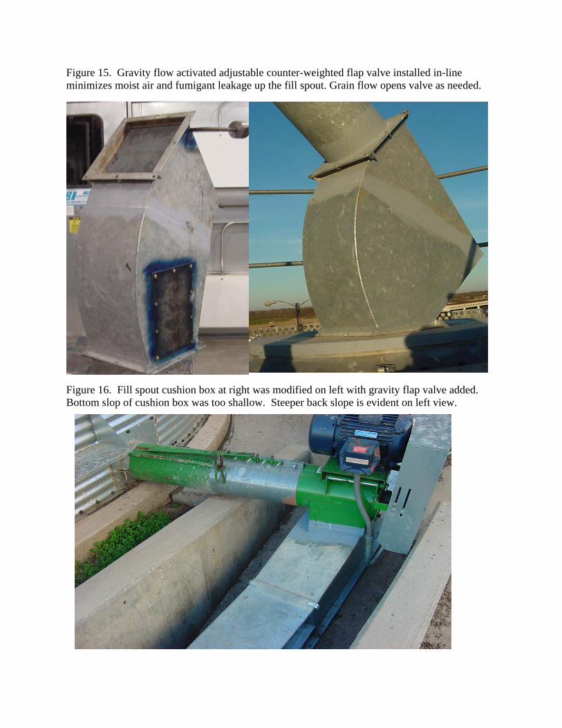
Sealing down spouts Down spouts should be sealed by installing an in-line gravity actuated flap valve like the one shown in Figure 15, or by adding a gravity weight actuated flap valve to the original cushion box shown in the right photo in Figure 16. The gravity actuated, weight controlled flap valve serves several important functions:
• It blocks flow of phosphine gas up the fill spout during fumigation. • It greatly reduces convection air currents in the bin, keeping grain more uniformly cool. • It blocks moist air from going up the fill spout and condensing into a stream of water that
creates a wet, moldy grain core from the peak down into the grain mass. • The modified flap valve in the modified cushion box will act as a grain cushion and at
low grain flows, will slow grain velocity and turn it downward toward the center of the bin below, before it hits the back plate of the cushion box, reducing impact velocity.
Another less desirable alternative is to spread the flange connection where the spout connects to the cushion box (right view) in Figure 16, so a thin metal slide plate can be inserted to block the spout opening. This would need the flange to be blocked on three sides with one side or the top open. A wide plate would be inserted during fumigation, while a stub plate about 1 inch wide would be inserted to seal the gap for full pipe flow. Although this will provide an excellent fumigation seal, the other advantages of the gravity actuated flow plate would not be available.
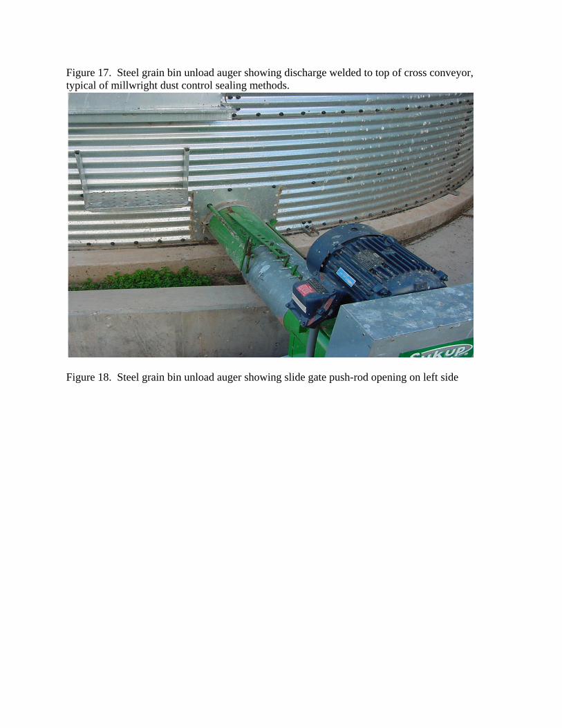
Sealing discharge conveyors Bin discharge conveyors have a natural partial seal in the discharge auger unload slide gate. The discharge slide gate should be closed fully before the bin is loaded as it is not a good practice to have grain laying in the auger trough for long periods. However, closed slide gates do not provide an insect tight seal. The unload auger should be kept completely sealed year-round except when grain needs to be unloaded from the bin. If the unload auger discharge is open and not welded to a cross conveyor like the unit shown in Figure 17, the opening can be sealed using spray adhesive, 6 mil poly sheeting and duct tape, or large heavy duty plastic bags (double bag to provide two layer protection) taped over or around the motor, drive and outlet. For unload augers with the outlet welded directly to another conveyor like the drag conveyor unit in Figure 17, an alternative sealing method must be used. One option is to "square cut" the connecting spout leaving at least a 1/4-inch or larger gap in the rectangular spout. Then weld two sets of flanges or flange rings with the flat faces facing separated by a 1/8-inch gap. This will allow a 12 gage steel plate to slide between the flanges providing a temporary, removable seal between the two conveyors. For rectangular flange rings, three sides can be sealed by punching matching bolt holes in 1/8 inch steel shim plates, leaving an opening on one side for a full width shut-off slide plate. When unloading grain with the slide plate removed and the slide plate slot can be taped shut to prevent grain leakage. An alternative sealing method is to cut an opening in the top of the auger that is closed by a hinged cover. The auger can then be foamed to completely fill the cross-section of the tube or U-trough opening, so the foam plug is about 6-12 inches thick along the auger shaft. When the bin is ready to be unloaded, the inspection door can be opened, part or most of the foam can be cut out, then the auger can be run to break out most of the foam. As grain flow slowly increases, the rest of the foam will be removed by the grain flow. For U-trough conveyors, cut a short section of the U-trough cover so it can be removed separately from the standard long cover panels. Foam directly under the opening until the foam rises slightly above the top flange of the open u-trough all the way across. Then set the cover plate down over the foam to provide a complete blockage of the U-trough. When it's time to use the unload conveyor, remove the short cover section and cut/dig out most of the foam. Food grade foam should be used so pieces of the foam in the grain will not be a significant contributor to contamination.
Sealing fill conveyors
Fill conveyors often have a discharge spout welded directly to the top of grain bins that can be modified like the unload conveyor system described above by cutting a slot out of the connecting spout, adding two facing flange rings and adding a cut-off slide plate, or bolting in a divider plate. The second option would be to cut an inspection opening and add a hinged door, or cut a short section of U-trough opening, as discussed above, then foam sealing the tube like the discharge conveyor.
Unload slide gate push-rod openings Unload slide gate push-rods have a clearance opening through a plate in the foundation ring of the bin that will allow insect entry and gas loss, Figure 18. With the slide gate fully closed, tape seal the rod and opening gap around the rod to seal the opening. An alternative is to use grease or foam to fill the opening with the gate fully closed. Do not use urethane or silicone caulk as these materials have strong adhesive bonds which may make it difficult to move the slide gate.
Elevator leg grain distributor and leg head-section vent sealing
Downspouts are suspected of inducing strong convection air movement up through grain bins and silos due to the differential wind velocities and associated negative pressure or suction created around the leg head section, vent and grain distributor that feeds the downspouts. Sealing the head section vent would minimize some convection movement, but the leg head vent should be open when the leg operates for proper leg discharge into the distributor.
Sealing elevator leg head-section vents The elevator leg head-section vent should be taped off with duct tape, but a flag marker should be attached to the sealed vent that will catch someone's attention after the fumigation, so the seal will be removed at the end of the fumigation. If not removed, the lack of vent air flow into the leg head-section may effect the discharge characteristic of the leg, causing some grain to drop out of its normal discharge trajectory and "back-leg." The double-handling of grain dropping back to the leg boot section may slow the handling rate of the leg. One method to permanently "seal" the elevator leg head-section vent except when the leg is running would be to add a motorized valve on a pipe extension connected to the vent inlet with the valve motor or coil wired in parallel with the leg motor starter. Thus, the normally closed valve would open each time the leg motor started, then be closed the remainder of the time.
Sealing leg distributors and leg trunks Manufacturers of elevator leg grain distributors have not been concerned with sealing distributors against air leaks. The distributor manufacturer's main concern has been keeping rain water out of the distributor. However, to minimize convection air suction, the distributor inspection plates, down spout flanges and/or connecting band joints on the distributor outlet
tubes should be well sealed with silicone caulk. The inspection door should be removed and a heavy silicone caulk bead placed around the opening to provide an air tight seal. The leg head discharge flange connected to the distributor inlet flange should also be well sealed. The distributor outlet should always be set on a "blank" position to minimize any suction of air up one of the spouts. Most legs are built in modular sections of 10 ft or 5 ft lengths with flanges that are jig welded in jigs or fixtures for flush fit with mating flanges and which keeps the leg plumb during assembly. However, not all flanges are tightly sealed at the time of assembly and erection. The joint at each leg trunk section should be silicone sealed around the flange on both the up-flow and down-flow trunk legs at each trunk section junction.
Sealing leg downspouts Sealing downspouts from bucket elevator distributors is very difficult, especially with elevator legs inside concrete head-houses. The ideal seal would be a gravity activated hinged flap valve with a rubber gasket face that fits flat against a square cut end of the downspout, preferably with the spout directed vertically. Most spouts on concrete elevators enter the silos at an angle, but if the ends were square cut, a hinged gravity spout could be bolted to the topside of the spout. These flap valves have a lever arm or a plate extension past the mounting hinge that is fitted with an adjustable counter-weight. The counter-weight is designed such that the weight and the lever-arm (distance from the pivot point) keeps the flap valve closed until a small amount of grain flows against the plate, then the valve will open. The degree of opining is related to the grain flow mass. Under full-flow, the valve should be almost completely open -- almost a 90 degree angle to the spout.).
Figure 1. Selection of primary sealing materials used for sealing silos and steel bins. Figure 2. Sealing concrete silo under-roof external vents with expandable closed cell foam. Applicator lies on foam pad and wears safety harness with lanyard tied to elevator structure.
Figure 3. Cardboard panels cut undersized to fit through vertical steel bars in under-roof vents for use as a backstop 1-2 inches behind steel bars to minimize foam volume.
Figure 4. Foam sealant and cardboard back plate with wire handle read to seal exterior under-roof vent. Note plastic bag with foam pad/blankets that applicator lies on near roof edge.
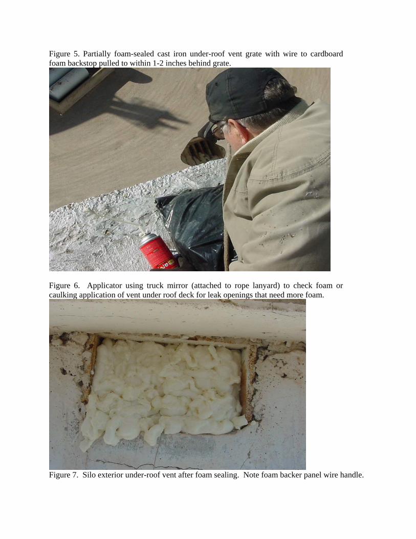
Figure 5. Partially foam-sealed cast iron under-roof vent grate with wire to cardboard foam backstop pulled to within 1-2 inches behind grate.
Figure 6. Applicator using truck mirror (attached to rope lanyard) to check foam or caulking application of vent under roof deck for leak openings that need more foam.
Figure 8. Silo discharge spout ready for sealing of wall flange and R&P slide gate with urethane sealant or silicone caulk.
Figure 9. Great Stuff closed cell foam insulation used to seal bins and silo openings. Figure 10. Foam sealing the roof-eave gap inside an empty steel bin using expandable foam.
Figure 11. Caulk sealing a bin with urethane or silicone sealants. Right view shows roof vent panel with caulking between two roof ribs that have been foam sealed. Figure 12. Roof panel stiffening rib seal plate. Caulk seal around the edges of the plate form inside or outside the bin, based on access convenience.
Figure 13. Pressure aeration centrifugal aeration fan inlet sealed. Note plastic below opening has been glued to the fan housing, but the plastic should still be duct taped across the bottom. Figure 14. Foam is best way to seal direct drive centrifugal blower motor shaft clearance hole.
Figure 15. Gravity flow activated adjustable counter-weighted flap valve installed in-line minimizes moist air and fumigant leakage up the fill spout. Grain flow opens valve as needed. Figure 16. Fill spout cushion box at right was modified on left with gravity flap valve added. Bottom slop of cushion box was too shallow. Steeper back slope is evident on left view.
Figure 17. Steel grain bin unload auger showing discharge welded to top of cross conveyor, typical of millwright dust control sealing methods. Figure 18. Steel grain bin unload auger showing slide gate push-rod opening on left side