SEATS Page Subject Page ..................... ~ntroduction ............. . Front Seats Full Width Front Seat Assembly . Manually Operated . . ................... Description ................. Seat Assembly .............. Adjuster Assembly Front Seat Assembly . Power Operated ................ (2, 4 and 6-Way) ................... Description Seat Assembly ....... 1. ......... ............... Adjuster Assembly Two-Way Seat Adjuster Components . .................... l1CI1 Body Electric Motor : ................ ............... Horizontal Gearnut Horizontal Jackscrew ............. Plastic Slides .................. Four-Way Seat Adjuster Components . .................... "A" Body ................. Electric Motor ................ Vertical Gearnut .............. Horizontal Actuator .................... Jackscrew Horizontal and Vertical Drive Cables ..... Transmission .................. Disassembly and Assembly of Transmission . Four-Way Seat Adjuster Components . Buick "B, C & E" Body ............ ................. Electric Motor ................ Vertical Gearnut .............. Horizontal Actuator Horizontal and Vertical Drive Cables .... .................. Transmission Disassembly and Assembly of Transmission . Six-Way Seat Adjuster Components . ................ "B. C & E" Body ................. Electric Motor .............. Horizontal Actuator ............ Front Vertical Gearnut ............. Rear Vertical Gearnut ...... Lower Channel and Plastic Slides ................. Upper Channel ..... Horizontal and Vertical Drive Cables .................. Transmission Disassembly and Assembly of Transmission . ................. Front Seat Eack Seat Back Assembly . Four Door . .............. with Standard Seat Seat Back Assembly (Right or Left) . ........ Two Door with Standard Seat "Strata" Seat Back Assembly (Right or ....... . Left) All Except 16639 Styles "Strato" Seat Back Assembly (Right or Left) . 16639 Styles ............. ......... Standard Seat Back Headrest .......... Front Seat Center Arm Rest Arm Rest and Curtain . Standard Full Width Seat Back ............... Arm Rest and Support . Standard Full Width Seat Back ............... Arm Rest and Curtain . Notch Down and Strato Seat Back ............. Arm Rest Assembly . Notch Down and ............... Strato Seat Back Arm Rest Support . Notch Down and ............... Strato Seat Back Foot Rest Assembly . Cadillac 68169 Styles . . .................... Bucket Seats .................... Description Manually Operated Bucket Seat Assembly ... Power Operated Horizontal or Four -Way Assembly .................... Manually Operated Bucket Seat Adjuster .... ...... Power Operated Horizontal Adjuster ...... Power Operated Four-Way Adjuster Power Operated Four-Way Adjuster ................... Components Motor and Transmission Drive Belt .................. and Pulleys ................ Motor Assembly Trallsinission Assembly and Drive Cables . . Disassembly and Assembly of Transmission . ........... Adjuster Vertical Gearnut ............... Adjuster Jackscrew ......... Adjuster Horizontal Actuator ............ Torque Tube Assembly Standard Bucket Seat Back . Two Door ............. Styles Except Corvair Standard Bucket Seat Back . Corvair ..... ..... Reclining Front Seat Back and Headrest ............ Reclining Front Seat Back ................... Description .............. Seat Back Assembly ................ Positioning Unit ............. Strato Seat Back Headrest ................... Description .............. Support Guide Tube ............... Headrest Supports ...................... Rear Seat ................ Rear Seat Cushion Rear Seat Back . All Except Corvair ..... Rear Seat Back Center Arm Rest and ..................... Curtain Rear Seat Back Center Arm Rest Hanger ............... Plate and Linkage ....... Folding Rear Seat Back . Corvair ...... Folding Rear Seat Back Assembly ....... Folding Rear Seat Back Linkage ..... Folding Rear Seat Back Filler Panel Station Wagon Folding Rear Seats and ............ Floor Panels . "B" Body Description .................... Rear Floor to Tail Gate Filler Panel .......... Assembly 25-26000 Series ...... Compartment Pan Side Filler Panel Luggage Compartment Front and Rear ..... . Panel Assemblies Two Seat Styles Luggage Compartment Rear Panel . Two ................... Seat Styles Luggage Compartment Front and Rear Panel Hinge ................... Folding Third Seat Cushion . Three ................... Seat Styles SEATS 10-1
Fig. 10-1-Seat Adjuster Floor Pan Attachment - "A, X & Z" Full Width Seat
Sea) Assembly
Removal and Installation
1. Remove both driver and passenger inner seat belt floor pan attaching bolt.
2. Remove door sill plates and turn back floor mat or carpeting, where necessary, to expose seat adjuster-to-floor pan attaching nuts o r bolts.
3. Operate seat to full forward position.
4. At rear of adjusters, remove adjuster-to-floor pan rear attaching nuts o r bolts (Fig. 10-1 and Fig. 10-2).
5. Operate seat to full rearward position. On "A, X & Zw Body Styles loosen adjuster- to-floor pan front attaching bolts, Then with aid of a helper, slide seat assembly rearward until front legs of adjusters a re disengaged from under front attaching bolts. Remove seat assembly from body.
On ('B & C" Body Styles remove adjuster-to- floor pan front attaching bolts. On Styles with seat back cigar lighter tilt seat assembly rear- ward sufficiently to disconnect lighter feed wire. With aid of a helper, remove seat as- sembly from body.
6. To install seat assembly, reverse removal procedure. Where seat ad juster-to-floor pan
spacers were present reinstall spacers in same position.
NOTE: On "A, X & Z" Body Styles make certain front legs of adjusters a re completely engaged under front attaching bolts before tightening bolts.
Check operation of seat assembly to full limits of travel.
Adjuster Assembly Removal and lnstallation
1. Remove front seat assembly with adjusters attached, a s previously described, and place upside down on a clean protected surface.
2. Remove seat adjuster assist spring from ad- juster to be removed (Fig. 10-3).
3. If left adjuster is being replaced, remove adjuster control knob.
4. Squeeze hooked end of seat adjuster locking wire together and slide retaining,. spring back over hump in locking wire and remove locking wire from adjuster.
5. Remove adjuster-to-seat bottom frame front and rear attaching bolts (Fig. 10-3) and removp seat adjuster from seat.
6. To install, reverse removal procedure.
NOTE: The right and left seat adjuster sliding mechanism should be in same relative position when attaching adjuster to seat bottom frame.
After installing adjusters to seat frame, check operation of adjusters. If adjusters do not lock o r unlock satisfactorily when control handle on left adjuster i s operated, disengag? locking wire re- tainer from hole in seat bottom frame and engage retainer in one of adjacent holes to obtain proper tension in wire. (Fig. 10-3)
FRONT SEAT ASSEMBLY-POWER OPERATED TWO, FOUR OR SIX-WAY FULL WIDTH SEAT Description. The seat adjusters a re actuated by a 12 volt, re- versible, shunt wound motor with a built in circuit breaker. The motor is energized by a toggle-type control switch installed in the left seat side panel o r in the left door arm rest.
On four-way and six way power operated seats the seat operating mechanism incorporates a trans- mission assembly which incorporates solenoids
SEATS 10-3
20000 SERIES
. WAY ELECTRIC ONLY) " /5-/ 47 // //
10000, 30000, 40000 SERIES 60000 SERIES
Fig. 10-2-Seat Adjuster Floor Pan Attachment - "B & C" Full Width Seat
and drive cables to the seat adjusters. On the four- way sdat one solenoid controls the horizontal move- ment of the seat while the second solenoid controls the vertical movement of the seat. On the six-way sea t one solenoid controls the vertical movement of the front of the seat, the second solenoid controls the horizontal movement of the seat and the third solenoid controls the vertical movement of the r e a r of the seat. When the control switch is actuated, the motor and one of the solenoids a r e energized simultaneously. Then the solenoid plunger engages with the driving gear dog. The driving gear rotates the drive cables and operates both adjusters. When the adjusters reach their limit of travel, the drive cables stop their rotating action and torque is ab- sorbed by the rubber coupler connecting the motor and transmission. When the control switch is re- leased, a return spring returns the solenoid plunger to i t s original position disengaging it from the driving gear dog.
Seat Assembly
Removal and Installation
1. Operate seat to full forward position. On four- way o r six-way power seats operate seat to full up position.
2. Remove both dr iver and passenger inner seat belt floor pan attaching bolt. Remove seat cushion side panels where present. Where seat adjuster track covers a r e present carefully pry out track cover snap in retainers with a flat- bladed tool and remove track covers.
3. Where necessary, remove sil l plates and turn back floor mat o r carpeting to expose seat adjuster-to-floor pan attaching nuts o r bolts.
4. Remove seat adjuster-to-floor pan rear at- taching bolts (Fig. 10-1 o r 10-2); then operate seat assembly to full rearward position.
5. a. On "A" Body Styles with power operated seat adjusters, loosen adjuster-to-floor pan front attaching bolts (Fig. 10-1). With aid of helper, slide seat assembly rearward until front legs of adjusters a re disengaged from under front attaching bolts. Tilt seat assembly rearward sufficiently to discon- nect seat harness feed connector and detach harness from clip on floor pan (Fig. 10-4): then remove seat assembly from floor pan.
b. On liB & C" Body Styles remove adjuster- to-floor pan front attaching bolts (Fig. 10-2). Tilt seat assembly rearward suf- ficiently to disconnect seat harness feed connector and detach harness from clip on floor pan (Fig. 10-5 for Two-Way, Fig. 10-6 for Four-Way, Fig. 10-7 for Six-Way and Fig. 10-8 for Strato Six-Way). On styles with seat back cigar lighter, seat
back courtesy lamps or seat back vanity lamp disconnect electrical feed wire o r wires. With aid of a helper remove seat assembly from body.
6. To install seat assembly, reverse removal procedure. Where seat adjuster-to-floor pan spacers were present reinstall spacers in same position.
NOTE: On "A" Body Styles make certain front legs of adjusters a r e completely engaged under front attaching bolts before tightening. Also check that carpet retainers a re installed under rear attaching bolts (Fig. 10-1) and that floor mat or carpet is properly positioned under retainers.
Make sure ground wire is securely attached under left seat adjuster-to-floor pan rear at- taching bolt. Check for proper operation of seat adjusters to limits of travel.
IMPORTANT: When installing seat assembly in body, seat adjusters should be parallel and "in phase" with each other. In the event the
SEATS 10-5
Fig. 10-4-Four-Way Full Width Seat Electric Wiring - "A" Styles
1. Control Switch Block 6. Vertical Drive Cable 2. Motor Control Relay (Yellow) 3. Motor 7. Horizontal Drive Cable 4. Rubber Coupler (B lack) 5. Harness Feed 8. Transmission Assembly
Connector 9. Seat Ground Wire
Fig. 10-5-Two-way Full Width Seat Electric Wiring - "C & E" Styles
1. Front Seat Back Switch 5. Motor Feed - White 6. Ground Wire
2. Front Seat Back Switch 7. Front Seat Back Ground - Black Courtesy Lamp Feed
3. Control Switch Connector (Cadi l lac Onl.y) 4. Harness Feed Connector 8.' Horizontal Control Cable
Fig. 10-6-Four-Way Ful I-Width Seat Electric Wiring - Buick "B, C & En Styles
2. Ground Wire 8. Transmission Assembly 3. Control Switch 9. Transmission End Plates 4. Motor 10. Horizontal Control 5. Motor Control Relay Cable (Black)
Fig. 10-7-Six-Way Full-Width Seat Electric Wiring - "B, C & E" Styles
1. Horizontal Control 7. Motor Control Relay Cable (Black) 8. Rubber Coupler
2. Rear Vertical Control 9. Harness Feed Cable (Blue) Connector
3. Ground Wire 10. Transmission and Solenoid 4. Motor Assembly 5. Control Switch 11. Front Vertical Control 6. Front Vertical Control Cable (Yellow) -
Cable (Yellow) - Right Side Left Side 12. Transmission End Plate
10-6 SEATS
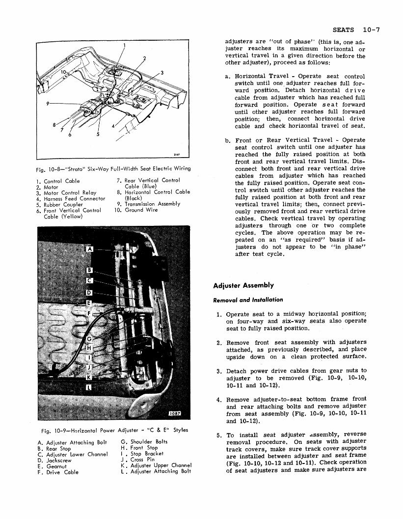
Fig. 10-8-"Strato" Six-Way Full-Width Seat Electric Wiring
1. Control Cable 7. Rear Vertical Control 2. Motor Cable (Blue) 3. Motor Control Relay 8. Horizontal Control Cable 4. Harness Feed Connector (B I ac k) 5. Rubber Coupler 9. Transmission Assembly 6. Front Vertical Control 10, Ground Wire
Cable (Yellow)
Fig. 10-9-Horizontal Power Adjuster - "C & E" Styles
A. Adjuster Attaching Bolt G. Shoulder Bolts B. Rear Stop H. Front Stop C. Adjuster Lower Channel 1 . Stop Bracket D. Jackscrew J . Cross Pin E . Gearnut K . Adjuster Upper Channel F . Drive Cable L . Adjuster Attaching Bolt
adjusters a r e "out of phase" (this is, one ad- juster reaches its maximum horizontal or vertical travel in a given direction before the other adjuster), proceed a s follows:
a. Horizontal Travel - Operate seat control switch until one, adjuster reaches full for- ward position. Detach horizontal d r i v e cable from adjuster which has reached full forward position. Operate s e a t forward until other adjuster reaches full forward position; then, connect horizontal drive cable and check horizontal travel of seat.
b, Front or Rear Vertical Travel - Operate seat control switch until one adjuster has reached the fully raised position at both front and rear vertical travel limits. Dis- connect both front 'and rear vertical drive cables from adjuster which has reached the fully raised position. Operate seat con- trol switch until other adjuster reaches the fully raised position at both front and rear vertical travel limits; then, connect previ- ously removed front and rear vertical drive cables. Check vertical travel by operating adjusters through one or two complete cycles. The above operation may be re- peated on an "as required" basis if ad- justers do not appear to be "in phase" after test cycle.
Adjuster Assembly
Removal and Installation
1. Operate seat to a midway horizontal position; on four-way and six-way seats also operate seat to fully raised position.
2. Remove front seat assembly with adjusters attached, a s previously described, and place upside down on a clean protected surface.
3. Detach power drive cables from gear nuts to adjuster to be removed (Fig. 10-9, 10-10, 10-11 and 10-12).
4. Remove adjuster-to-seat bottom frame front and rear attaching bolts and remove adjuster from seat assembly (Fig. 10-9, 10-10, 10-11 and 10-12).
5. To install seat adjustel. dssembly, reverse removal procedure. On seats with adjuster track covers, make sure track cover supports a re installed between adjuster and seat frame (Fig. 10-10, 10- 12 and 10-11). Check operation of seat adjusters and make sure adjusters a re
SEATS 10-7
Fig. 10-10-Front Seat Assembly - Four-Way Ti l t - Buick "B, C & E" Styles
A. Ad juster-to-Seat Attaching D. Horizontal Actuator G. Motor Attaching Screws Bolts E. Track Cover Supports H . Transmission Attaching
B . Horizontal Cables - Black F. Motor and Transmission Screws C. Vertical Gearnut Support Attaching Screws I . Rear Vertical Cables - Blue
((in phase" before installing assembly into Electric Motor-"C" Body body (See Step 6 under '(Front Seat Assembly - Removal and InstallationJ'), Removal and installation
1. Remove front seat assembly a s previously TWO-WAY SEAT ADJUSTER MAJOR described and place upside down on a clean COMP0NENTS"C" BODY FULL protected surface. WIDTH SEATS
2. Disconnect both power drive cables from actu- The following service procedures cover replace- ator motor. ment of the major component parts of the power operated two-way seat adjusters used on ((C" body 3. Remove screws that secure actuator motor full width seats. support bracket to seat bottom frame and
10-8 SEATS
remove actuator motor with attached support bracket from seat assembly.
4. Disconnect feed wire harness from actuator motor (Fig. 10-5).
5. Remove screws securing motor to motor sup- port bracket.
6. To install, reverse removal procedure. Check for proper seat operation to extreme limit of fore and aft travel.
Horizontal Gearnut Assembly-"C" Body
Removal and Installation
1. Remove front seat asgembly with attached adjusters and place upside down on a clean, protected surface.
2. Detach power drive cable from gearnut to be removed.
3. Using a "clutchJJ type screwdriver o r other suitable tooL, remove two shoulder bolts se- curing gearnut to upper slide portion of seat adjuster (Fig. 10-9).
4. Rotate jackscrew assembly upward sufficiently to gain access to cotter pin at rea r of jack- screw assembly.
5. Remove cotter pin, washer and rubber bumper from r ea r end of jackscrew; then, remove gearnut from jackscrew.
6. To install, reverse removal procedure. P r i o r to installing seat assembly in body, be sure adjusters a r e "in phase". See step 6 under " F r o n t S e a t A s s e m b l y - Removal and Installation".
Horizontal Jackscrew-"C" Body
Removal and Installation
1. Remove front seat assembly with attached adjusters and place upside down on a clean, protected surface. \
2. Detach power drive cable from gearnut and jackscrew assembly to be removed.
3. Using a suitable tool (preferably a uclutch'J type screwdriver) remove two shoulder bolts securing gearnut to upper slide portion of seat adjuster assembly (Fig. 10-9).
4. Remove retainer that secures stop bracket crosspin to adjuster front pedestal and remove crosspin (Fig. 10-9).
5. Remove jackscrew assembly f r o m s e a t adjuster .
6. To install, reverse removal procedure.
NOTE: When replacing jackscrew assembly with new part, remove nut, washers, rubber bumper and stop bracket with inserted rubber grommet from front end of jackscrew, a s well a s gearnut and washers, rubber bumper and cotter pin from rear end of jackscrew and transfer to new jackscrew assembly.
Plastic Slides-"C" Body
Removal and Installation
1. Remove front seat adjuster to be serviced from front seat assembly. (See: Front Seat Adjuster - Two-Way Electric - Removal and Installation procedures).
2. Using a suitable tool (preferably a "clutch" type screwdriver), remove two shoulder bolts securing gearnut to upper channel of seat ad- juster assembly (Fig. 10-9).
3. Slide lower track and support base portion of seat adjuster, with attached jackscrew and gearnut, forward until i t disengages from upper channel assembly. The four plastic slides may now be disengaged from positioning slots on lower track.
4. To install, reverse removal procedure making sure that groove in plastic slide slips onto lower track with thinner section of slide pro- truding above surface of track.
FOUR-WAY SEAT ADJUSTER MAJOR COMP0NENTS"A" BODY FULL WIDTH SEATS
The following service procedures cover replace- ment of the major component par ts of the power operated four-way seat adjusters used on the "A" body full width seats.
Electric Motor-"A" Body
Removal and Installation
1. Remove front seat assembly a s previously described and place upside down on a clean protected surface.
SEATS 10-9
Fig. 10-11-Front Seat Assembly - Four-Way Tilt - "A" Styles
A. Adjuster to Seat Frame Attaching Bolts
€3. Motor Assembly C. Transmission Assembly
D. Track Cover Supports E . Motor and Transmission
Support Attaching Screws
F . Vertical Cable (Yellow) G. Horizontal Cable (Black)
2. Disconnect wire harness from motor relay assembly .
3, Remove screws securing motor and transmis- sion support to seat bottom frame. (Fig. 10-11)
4. Remove motor-to-motor support attaching screws and remove motor assembly from support.
5. To install, reverse removal procedure making sure rubber coupler is properly engaged at both motor and transmission ends. Check op- eration of seat to full limits of travel.
Vertical Gearnut-"A" Body
Removal and installation
1. Operate seat assembly tu fully raised and mid- way position.
2. Remove front seat assembly from body a s previously described and place upside down on a clean protected surface.
3. Detach vertical gearnut drive cable from other - adjuster.
4. Using a clutch type ,screwdriver or other suit- able tool, remove shoulder screws securing linkage to vertical gearnut ,being replaced (Fig. 10-13).
5. If right adjuster gearnut is being replaced, at front of jackscrew, remove double nut that acts a s a jackscrew "down" stop.
6. Using a portable power source to energize the motor, actuate vertical gearnut until gear- nut is disengaged from jackscrew.
NOTE: It may be necessary to manually raise or lower upper rear portion of adjuster to gain clearance for removal of gearnut.
A. Track Cover Support E . Horizontal Actuator H. Motor Attaching Screws B . Adjuster-to-Seat Attaching F . Horizontal Cables - 1 . Transmission Attaching Screws
Screws Black J. Rear Vertical Cables - Blue C. Rear Vertical Geamut G. Motor and Transmission K. Front Vertical Cables - Yellow D. Track Cover Support Support Attaching Screws L. Front Vertical Gearnut
7. Disconnect drive cable from gearnut.
8. To install, reverse removal procedure.
NOTE: Check operation of seat adjusters and make sure adjusters a re "in phase". See step 6 under "Front Seat Assembly - Removal and Installation)).
Horizontal Actuator-"A" Body
Removal and Installation
1. Remove adjuster vertical gearnut a s previ- ously described.
2. Disconnect d r i v e cable from horizontal actuator.
3. Remove screws securing horizontal actuator assembly to adjuster lower track; then remove actuator from adjuster assembly (Fig. 10- 13).
4. To install, reverse removal procedure.
NOTE: When installing horizontal actuator, adjust actuator so that drive gear is fully en- gaged with teeth on lower channel. When hori- zontal actuator attaching screws a re tightened, there should be no free motion between upper and lower channels. Read just actuator "as required)) un t i 1 all free motion between
SEATS 10-11
VERTICAL GEAR
HORIZONTAL ACTUATOR SCREWS
H O R I Z O N T A L ACTUATOR
1915
Fig. 10-13-Four-Way Seat Adjuster - "A" Styles
channels has been removed. Check operation of seat adjusters and make sure adjusters a r e "in phase". See step 6 under "Front Seat Assembly - Removal and Installation".
Jackscrew-"A" Body
Removal and Installation
1. Remove adjuster vertical gearnut a s previ- ously described.
2. Remove seat adjuster-to-seat bottom frame front and rear attaching bolts on side affected (Fig. 10-11).
3 . As a bench operation, remove jackscrew-to- adjuster linkage attaching rivet and remove jackscrew f r o m adjuster assembly (Fig. 10- 14).
NOTE: It may be necessary to manually raise o r lower upper rea r portion of adjuster to gain access to jackscrew attaching rivet.
4. To install, reverse removal procedure. Check operation of seat adjusters and make sure adjusters a r e "in phaseH. See step 6 under " F r o n t S e a t A s s e m b l y - Removal and Installationw.
Horizontal and Vertical Drive Cables-"A" Body
Removal and lnstallation
1. Remove front seat assembly from body with attached adjusters, motor and transmission and place upside down on a clean protected surface.
2. Detach both horizontal and vertical cables from seat adjuster.
3. Remove screws securing horizontal and verti- cal cable end plate on side of transmission from which cables a r e being removed and re- move cables from seat assembly (Fig. 10-4).
4. Disengage cable to be replaced from end plate,
5. To install cables, reverse removal procedure, Check operation of seat to full limits of travel.
Transmission-"A" Body
Removal and lnstallation
1. Remove front seat assembly from body with attached adjusters, motor and transmission and place upside down on a clean protected surface.
2. Disconnect wire harness connector from trans- mission (Fig. 10-4).
3. Remove screws securing horizontal and verti- cal cable end plate on both sides of transmis- sion and detach cables from transmission.
4. Remove transmission to support attaching bolts; then, disengage transmission from rub- ber coupler and remove transmission from seat assembly.
5. To install, reverse removal procedure.
Disassembly and Assembly of Transmission
1. Remove front seat adjuster transmission from seat assembly.
Fig. 10-14-Four-Way Seat Adjuster - "A" Styles
10-12 SEATS
GEAR HOUSING DRIVING GEAR \ GEAR \
HARNESS SOLENOID CONNECTOR PLUNGER
I /
I
THRUST WASHER
\ 1 \ I SOLENOIDS AND SOLENOID RUBBER COUPLER DOG SPRING DOG SHAFT COVER PLATE HOUSING , ,93
Fig. 10-1 5-Four-Way Seat Adjuster Transmission
2. Remove screws securing gear and solenoid housings together; then, carefully separate housings and remove component parts of trans- mission assembly (Fig. 10-15).
3 . To assemble transmission, reverse removal procedure.
IMPORTANT: Pr ior to o r during installation, lubricate frictional surfaces of driving gear thrust washer, gears, dog washers, shaft and solenoid plungers with ~Lubriplate" (630AAW) o r equivalent.
4. Remove motor-to-support attaching screws and remove motor assembly from support.
5. To install, reverse removal procedure making sure rubber coupler i s properly engaged at both motor and transmission ends. Check that seat harness is properly secured to seat (Fig. 10-6). Check operation of seat to full limits of travel.
Vertical Gearnut-Buick "B-C & E" Body
Removal and lnstallation
FOUR-WAY SEAT ADJUSTER MAJOR COMPONENTS-BUICK "B-C & E" FULL
1. Operate seat to rearward position; then, re- move front seat assembly and seat adjuster.
WIDTH FOUR-WAY POWER SEAT
The following service procedures cover replace- ment of the major component parts of the power operated four-way seat adjusters used on the Buick "B-C & E" body full width seats.
Electric Motor-Buick "B-C & E" Body
Removal and lnstallation
1. Femove front seat assembly, and place upside down on a clean protected surface.
2. Disconnect wire harness from motor relay assembly (Fig. 10-6).
3 . Remove screws securing motor and transmis- sion support to seat bottom frame (Fig. 10-10).
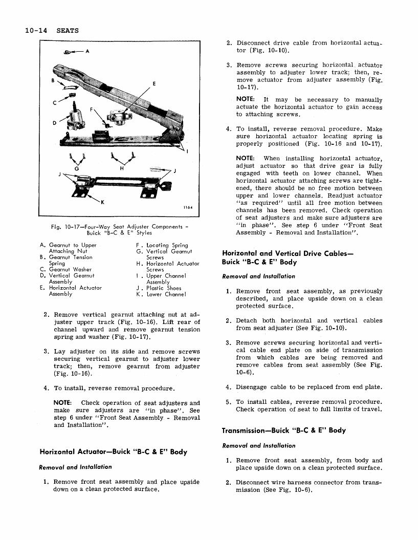
Fig. 10-17-Four-Way Seat Adjuster Components - Buick "B-C & E l 1 Styles
A. Gearnut to Upper Attaching N u t
B. Gearnut Tension Spring
C. Gearnut Washer D. Vertical Gearnut
Assembly E. Horizontal Actuator
Assembly
F . Locating Spring G. Vertical Gearnut
Screws H. Horizontal Actuator
Screws I . Upper Channel
Assembly J . Plastic Shoes K . Lower Channel
2. Remove vertical gearnut attaching nut a t ad- juster upper track (Fig. 10-16). Lift r e a r of channel upward and remove gearnut tension spring and washer (Fig. 10-17).
3 . Lay adjuster on i ts side and remove screws securing vertical gearnut to adjuster lower track; then, remove gearnut from adjuster (Fig. 10-16).
4. To install, reverse removal procedure.
NOTE: Check operation of seat adjusters and make sure adjusters a r e ((in phase)'. See step 6 under '(Front Seat Assembly - Removal and Installation".
2. Disconnect drive cable from horizontal actua- tor (Fig. 10-10).
NOTE: It may be necessary to manually actuate the horizontal actuator to gain access to attaching screws.
4. To install, reverse removal procedure. Make sure horizontal actuator locating spring is properly positioned (Fig. 10- 16 and 10- 17).
NOTE: When installing horizontal actuator, adjust actuator so that drive gear is fully engaged with teeth on lower channel. When horizontal actuator attaching screws a r e tight- ened, there should be no free motion between upper and lower channels. Read just actuator ( (as requiredyy until all free motion between channels has been removed. Check operation of seat adjusters and make sure adjusters a r e "in phase". See step 6 under ((Front Seat Assembly - Removal and Installation".
Horizontal and Vertical Drive Cables- Buick "8-C & E" Body
Removal and Installation
1. Remove front seat assembly, a s previously described, and place upside down on a clean protected surface.
2. Detach both horizontal and vertical cables from seat adjuster (See Fig. 10-10).
3. Remove screws securing horizontal and verti- cal cable end plate on side of transmission from which cables a r e being removed and remove cables from seat assembly (See Fig. 10- 6).
4. Disengage cable to be replaced from end plate.
5. To install cables, reverse removal procedure. Check operation of seat to full limits of travel.
Transmission-Buick "B-C & E" Body
Removal and Installation Horizontal Actuator-Buick "B-C & E" Body
Removal and Installation
1. Remove front seat assembly and place upside down on a clean protected surface.
1. Remove front seat assembly, from body and place upside down on a clean protected surface.
2. Disconnect wire harness connector from trans- mission (See Fig. 10-6).
10-14 SEATS
3 . Remove screws securing horizontal and verti- cal cable end plate on both sides of transmis- sion and detach cables from transmission.
4. Remove transmission to support attaching bolts; then, disengage transmission from rub- ber coupler and remove transmission from seat assembly.
5. To install, reverse removal procedure.
Disassembly and Assembly of Transmission
1. Remove front seat adjuster transmission from seat assembly.
IMPORTANT: Pr io r to o r during installation, lubricate frictional surfaces of driving gear thrust washer, gears, dog washers, shaft and solenoid plungers with ((Lubriplate" (630AAW) o r equivalent.
2. Remove screws securing gear and solenoid housings together; t h e n, carefully separate housings and remove component par ts of trans- mission assembly (Fig. 10- 15).
3 . To assemble transmission, reverse removal procedure.
SIX-WAY SEAT ADJUSTER MAJOR COMPONENTSL'B-C & E" BODY FULL WIDTH SEATS
The following service procedures cover replace- ment of the major component parts of the power operated six-way seat adjusters used on the "B, C and E" body full width seats.
Electric Motor-"B-C & E" Body
Removal and lnstallation
1. Remove front seat assembly, a s previously described, and place upside down on a clean protected surface.
2. Disconnect motor feed wires from motor con- t rol relay (See Fig. 10-7).
3. Remove motor support-to- seat frame attaching bolts.
4. Remove motor-to-support attaching bolts; then move motor assembly outboard (away from transmission) sufficiently to disengage motor from rubber coupling.
. To install, reverse removal procedure making sure rubber coupling is properly engaged at both motor and transmission. Check that seat harness is properly secured to seat (See Fig. 10-7). Check operation of seat to full limits of travel.
Horizontal Actuator-"B-C & E" Body
Removal and Installation
1. Remove seat assembly from body a s previ- ously described and place upside down on a clean protected surface.
NOTE:. Horizontal Actuator is easily acces- sible with seat in mid-way o r approximate center position.
2. Detach three power drive cables from adjuster to be removed.
3 . Remove screws securing seat adjuster to seat bottom frame and .remove adjuster from seat assembly.
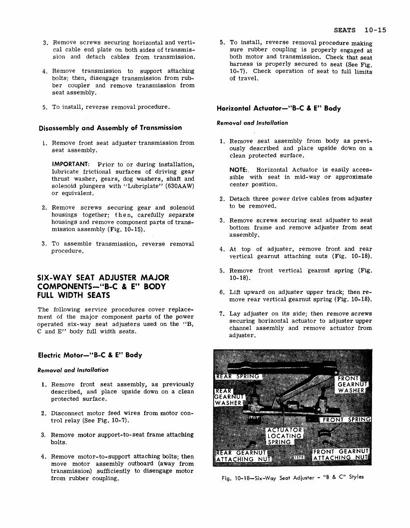
4. At top of adjuster, remove front and rear vertical gearnut attaching nuts (Fig. 10- 18).
5. Remove front vertical gearnut spring (Fig. 10- 18).
6. Lift upward on adjuster upper track; then re- move r ea r vertical gearnut spring (Fig. 10-18).
7. Lay adjuster on i t s side; then remove screws securing horizontal actuator to adjuster upper channel assembly and remove actuator from adjuster .
A. Upper Channel Assembly G. Front Vertical Gearnut B . Rear Vertical Gearnut Attaching Screws
Attaching Screws H , Plastic Shoe C. Lower Channel I . Actuator Locating D. Rear Spring Spring E, Rear Gearnut J . Horizontal Actuator
Attaching N u t K . Front Spring F. Actuator Attaching L . Front Gearnut
Screws Attaching Screw
IMPORTANT: Horizontal actuator is under tension from spring shown in Figure 10-18. When installing actuator, be sure actuator lo- cating spring is properly engaged with actuator assembly.
8. To install, reverse removal procedure. When installing horizontal actuator, be sure actuator drive gear is full engaged with teeth on lower channel. With tension spring properly installed and actuator attaching screws tight, there should be no free motion between upper and lower adjuster channels. Re-adjust actuator ( (as required') until all free motion between channels has been removed. Be sure seat adjusters a re "in phase", before installing seat assembly into body. (See step 6 under " F r o n t S e a t A s s e m b l y - Removal and Installation").
Front Vertical Gearnut-"B-C & E" Body
Removal and lnstallation
1. Operate seat to either full forward o r full rearward position.
2. Remove front seat assembly from body a s previously described and place upside down on a clean protected surface.
3 , Detach three power drive cables f rom adjuster to be removed.
4. Remove screws securing seat adjuster to seat bottom frame and remove adjuster from seat assembly.
5. At top of adjuster, remove front vertical gear- nut attaching nut.
6. Remove front vertical gearnut spring (Fig. 10- 18).
7. Lay adjuster on i ts side and remove front vertical gearnut attaching screws (Fig. 10-19); then remove gearnut f rom adjuster.
8. If front vertical gearnut is being replaced with a new part, transfer gearnut washer to new gearnut assembly (Fig. 10- 18).
9. To install, reverse removal procedure. Be sure adjusters a r e "in phase" before install- ing seat assembly into body. (See step 6 under " F r o n t S e a t A s s e m b l y - Removal and Installation").
Rear Vertical Gearnut-"B-C & E" Body
Removal and Installation
1. Operate seat to full forward position.
2. Remove front seat assembly from body a s previously described and place upside down on a clean protected surface.
3 . Detach three power drive cables from adjuster to be removed.
4. Remove screws securing seat adjuster to seat bottom frame and remove adjuster from seat assembly.
5. At top of adjuster, remove r ea r vertical gear- nut attaching nut (Fig. 10- 18).
6. Lift r e a r of channel upward and remove r ea r vertical gearnut spring (Fig. 10- 18).
7. Lay adjuster on i t s side and remove r ea r vertical gearnut attaching screws; then remove gearnut from adjuster (Fig. 10- 19).
8. If r e a r vertical gearnut is being replaced with a new part, transfer gearnut washer to new gearnut assembly (Fig. 10- 18).
10-16 SEATS
9. To install, reverse removal procedure. Be sure rea r gearnut spring is properly engaged under adjuster upper channel before tightening r ea r gearnut upper attaching nut, In addition, be sure adjusters a r e "in phase)' prior to in- stalling seat assembly into body. (See step 6 under "Front Seat Assembly - Removal and Installation'?).
Lower Channel and Plastic Slides- "B-C & E" Body
Removal and Insta1,ation
1. Remove horizontal actuator a s previously described.
2. Slide seat adjuster low& channel from upper channel until lower channel is completely dis- engaged from upper channel. Remove plastic slides from lower channel.
3. If lower channel i s being replaced with a new part, transfer plastic slides to new part (Fig. 10-19).
4. Apply "Lubriplate" (630AAW) o r equivalent to track portion of upper channel, plastic slides and teeth on lower channel.
5. To install, reverse removal procedure. Be sure adjusters a r e ('in phase)' before install- ing seat assembly into body. (See step 6 under ( ( F r o n t S e a t A s s e m b l y - Removal and Installation").
Upper Channel-"B-C & E" Body
Removal and lnstallation
1. Remove seat assembly from body and place upside down on a clean protected surface.
2. Detach three power drive cables from adjuster to be removed.
3. Remove screws securing seat adjuster to seat bottom frame and remove adjuster from seat assembly.
4. Remove horizontal actuator from upper channel as previously described.
5. Slide lower channel until i t is completely dis- engaged from upper channel; then transfer lower channel to new upper channel.
NOTE: Be sure sliding surfaces of upper and lower channels a r e properly lubricated with "Lubriplate" (630A~W) o r equivalent.
6. Transfer front and rear gearnuts to new upper channel (Fig. 10-19).
7. Install horizontal actuator and actuator locating spring to new upper channel.
8. Install adjuster to seat bottom frame: then check all operations of adjusters. Be sure adjusters a r e "in phase" prior to installing seat assembly into body. (See step 6 under " F r o n t S e a t A s s e m b l y - Removal and Installation").
9. Install seat assembly into body. Operate seat through several complete cycles to insure proper operation.
Horizontal and Vertical Drive Cables- "B-C & E" Body
Removal and Installation
1. Remove front seat assembly from body with attached adjusters, motor and transmission and place upside down on a clean protected surface.
2. Detach both horizontal and vertical cables from seat adjuster.
3 . Remove screws securing horizontal and verti- cal cable end plate on side of transmission from which cables a r e being removed and re- move cables from seat assembly; then dis- engage cables from end plate.
4. To install horizontal and vertical cables, re- verse removal procedure. Make sure colored drive cables a r e installed to proper gearnw and horizontal actuator a s shown in Figure 10-12.
Transmission-"B-C & E" Body
Removal and Installa,tion
1. Remove front seat assembly from body with attached adjusters, motor and transmission and place upside down on a clean protected surface.
2. Disconnect wire harness connector from trans- mission (See Fig. 10-7).
3 . Remove screws securing horizontal and verti- cal cable end plate, on both sides of transmis- sion and detach cables from transmission.
4. Remove transmission to support attaching bolts; then disengage transmission from motor
drive coupling and remove transmission from seat assembly.
FRONT SEAT BACK
Seat Back Assembly-Four Door Style with 5. To install, reverse removal procedure. Make
sure seat harness is properly secured to seat. Standard Full Width Seat
(See Fig. 10-7). Removal and Installation
Disassembly and Assembly of Transmission
1. Remove front seat adjuster transmission from seat assembly.
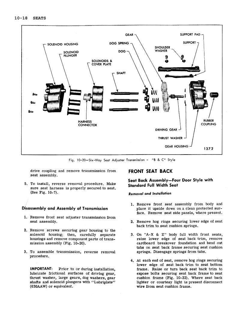
2. Remove screws securing gear housing to the solenoid housing; then, carefully separate housings and remove component parts of trans- mission assembly (Fig. 10-20).
3. To assemble transmission, reverse removal procedure.
IMPORTANT: Prior to o r during installation, lubricate frictional surfaces of driving gear, thrust washer, large gears, dog washers, gear shafts and solenoid plungers with "Lubriplate" (630AAW) o r equivalent.
1. Remove front seat assembly from body and place it upside down on a clean protected sur- face. Remove seat side panels, where present.
2. Remove hog rings securing lower edge of seat back trim to seat cushion springs.
3. On "A-X & Z" body full width front seats, raise lower edge of seat back trim, remove cardboard breakover foundation and bend out tabs on seat back frame securing seat cushion springs. Disengage springs from tabs.
4. At each end of seat, remove hog rings securing lower edge of seat back trim to seat bottom frame. Raise or turn back seat back tr im to expose bolts securing seat back frame to seat cushion frame (Fig. 10-22). Where seat back lighter or courtesy light is present disconnect wire from seat cushion frame.
10-18 SEATS
5. Place seat assembly in upright position. Then with a helper, holding seat back assembly, re- move seat back attaching bolts on each side of seat and remove seat back assembly.
6. To install seat back assembly, reverse re- moval procedure.
Seat Back Assembly-(Right or Left) - Two Door Style with Standard Full Width Seat
Removal and Installation
1. a. On seat with seat cushion side panel, re- move side panel and detach seat cushion t r im sufficiently to expose outer hinge pin and retainer.
b. On seats with outer hinge a r m cover, re- move screw securing cover and remove cover.
2. Using a flat bladed tool carefully remove re- tainer securing seat back outer a r m to hinge pin.
3. Carefully disengage seat back outer a r m from hinge pin; then, tilt seat back forward and up- ward to disengage seat back inner a r m from hinge pin and remove seat back from body.
4. To install seat back assembly, reverse re- moval procedure making sure washers a r e in- stalled over hinge pins prior to installing seat back. If outer retainer is damaged, install new retainer.
Fig. 10-22-Seat Back Attachment
"Strato" Front Seat Back Assembly (Right or Left) -Full Width Seat All Styles Except 16639 Style
Removal and Installation
1. Remove front seat assembly a s described under, "Full Width Front Seat Assembly - Removal and Installation".
2. At side of seat from which seat back is being removed, remove hog rings securing cushion side t r im at r e a r of seat and fold t r im forward sufficiently to expose two seat back outer at- taching bolts (Fig. 10- 23).
SEAT BACK I N N E R A T T A C H I N
Fig. 10-21 -Seat Cushion-to-Back Spring Attachment Fig. 10-23-Strato Ful l Width Seat Back Attachment
SEATS 10-19
Fig. 10-24-Strato Full Width Seat Back Attachment - Chevrolet 16639 Style
3. At inboard side of seat back, remove screw 2. Remove seat side panel on side from which securing inner attaching bolt cover plate and seat back is being removed. Remove hog rings remove cover plate. securing seat cushion t r im side facing at r e a r
of seat and turn side facing forward sufficiently 4. Remove seat back inner attaching bolts; then, to expose seat back outer a r m attaching bolts
remove outer attaching bolts and remove seat (See Fig. 10-23). back assembly from seat.
5. To install seat back assembly, reverse re- 3. Using a suitable hooked end tool between seat moval procedure. Make certain seat side panel back and seat cushion, at location "A", . r e -
support (Fig. 10-23) is secured under seat move retaining ring locking seat back at inner back outer attaching bolts. hinge (see View ‘(A", Fig. 10-24).
4. Remove seat back outer a rm attaching bolts "Strato" Front Seat Back Assembly (Fig. 10-23). (Right or Left) -Full Width Seat-1 6639 Style
5. Carefully tilt seat back forward. Remove inner
Removal and installation hinge bolt cover plate. Remove inner hinge bolts (Fig. 10-24) and carefully remove seat
1. Remove seat assembly from body, a s previ- back from seat assembly.
ously described, and place seat right side up on a clean surface. 6. To install, reverse removal procedure.
10-20 SEATS
HOOK S L O T
Fig. 10-25-Front Seat Center Arm Rest (Full Width Seat Back)
NOTE: It is important that removal procedure be reversed step by step when installing seat back assembly.
Standard Full Width Seat Back Head Rest (Drivers or Passengers Side)
The standard full width seat back headrest is se- cured by a support which is screwed o r welded to the seat back frame. The support incorporates a detent spring which allows the headrest to be raised o r lowered to four different height positions. The headrest can be removed from the seat back for storage by pulling the headrest bar out of the support .
To remove and install the headrest support, the seat back t r im must be removed and the support- to-seat back frame screws removed.
NOTE: On styles where the support is welded to the seat back frame, the welds must be cut to remove the support.
NKAGE SCaEWS
Fig. 10-26-Front Seat Center Arm Rest (Notch Down Seat Back)
FRONT SEAT CENTER A R M REST
Arm Rest and Curtain Assembly-Front Seat with Standard Full Width Seat Back
Removal and Installation
1. Place center a r m res t in down position.
2. At top of a r m rest curtain, remove two screws securing curtain to seat back frame (Fig. 10-25) and pull curtain forward to expose screws securing a r m res t to support linkage (Fig. 10-25).
3. Remove a r m rest-to-support linkage screws (Fig. 10-25) and remove a r m res t and curtain from seat.
4. To install, reverse removal procedure.
Arm Rest and Support Assembly-Front Seat with Standard Full Width Seat Back
Removal and Installation
1. Place center a r m res t in down position.
2. At top of a r m rest curtain, remove two screws securing curtain to seat back frame (Fig. 10-25).
3. Remove two screws securing a r m res t to sup- ports on seat back (Fig. 10-25); then, carefully lift a r m rest and linkage upward to disengage hooks of a r m rest f rom slots in supports and remove assembly from seat.
4. To install, reverse removal procedure. Pr io r to installing curtain screws check alignment and operation of a r m rest.
SEATS 10-21
Front Seat Center Arm Rest and Curtain Assembly-Front Seat with Notch Down Seat Back and Strato Front Seat
Removal and lnstallation
1. Lower a r m . res t to approximately 2 inches short of full down position.
2. Carefully pull curtain back sufficiently to re- move screws securing center a r m rest to support linkage and loosen outer screws se- curing curtain retainer to a r m rest (Fig. 10-26).
3 . Remove screw finishing covers (Fig. 10-26). Disengage a rm rest from support linkage and turn a rm rest upside down on t r im panel fin- ishing cover with curtain attached. Remove three screws securing curtain retainer to t r im panel finishing cover (Fig. 10-26); then remove a r m rest and curtain from seat.
4. To install, reverse removal procedure.
Front Seat Center Arm Rest Assembly- Front Seat with Notch Down Seat Back and Strato Front Seat
Removal and lnstallation
1. Place a r m rest in up position.
2. Working between a rm rest and seat back, re- move fastener a t both sides of a r m res t se- curing front end of screw finishing covers (Fig. 10-26).
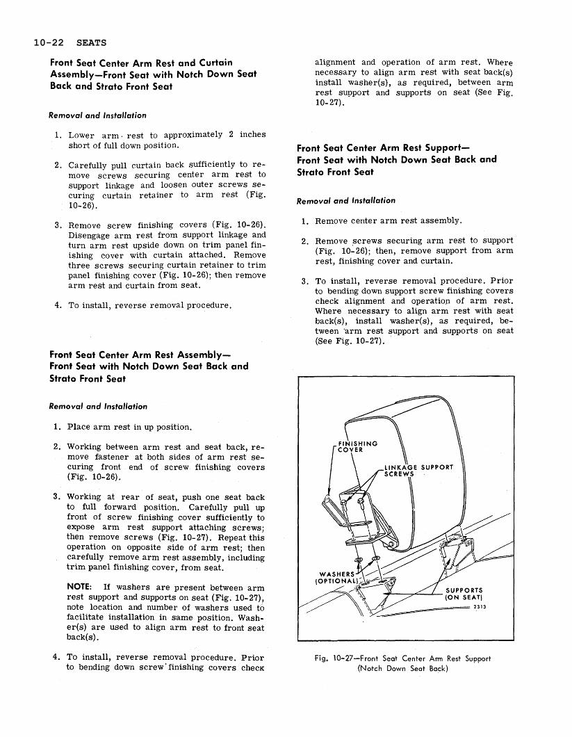
Working at r e a r of seat, push one seat back to full forward position. Carefully pull up front of screw finishing cover sufficiently to expose a r m rest support attaching screws; then remove screws (Fig. 10-27). Repeat this operation on opposite side of a r m rest; then carefully remove a r m rest assembly, including t r im panel finishing cover, from seat.
NOTE: If washers a r e present between a r m rest support and supports on seat (Fig. 10-27), note location and number of washers used to facilitate installation in same position. Wash- e r ( ~ ) a r e used to align a r m rest to front seat back(s) .
4. To install, reverse removal procedure. Pr io r to bending down screw ' finishing covers c h e c ~
alignment and operation of a r m rest . Where necessary to align a r m rest with seat back(s) install washer(s), a s required, between arm rest support and supports on seat (See Fig. 10- 27).
Front Seat Center Arm Rest Support- Front Seat with Notch Down Seat Back and Strato Front Seat
Removal and Installation
1. Remove center a r m rest assembly.
2. Remove screws securing a r m rest to support (Fig. 10-26); then, remove support from a r m rest , finishing cover and curtain.
3 , To install, reverse removal. procedure. Pr io r to bending down support screw finishing covers check alignment and operation of a rm rest. Where necessary to align a r m rest with seat back(s), install washer(s), a s required, be- tween 'arm res t support and supports on seat (See Fig. 10-27).
Fig. 10-27-Front Seat Center Arm Rest Support (Notch Down Seat Back)
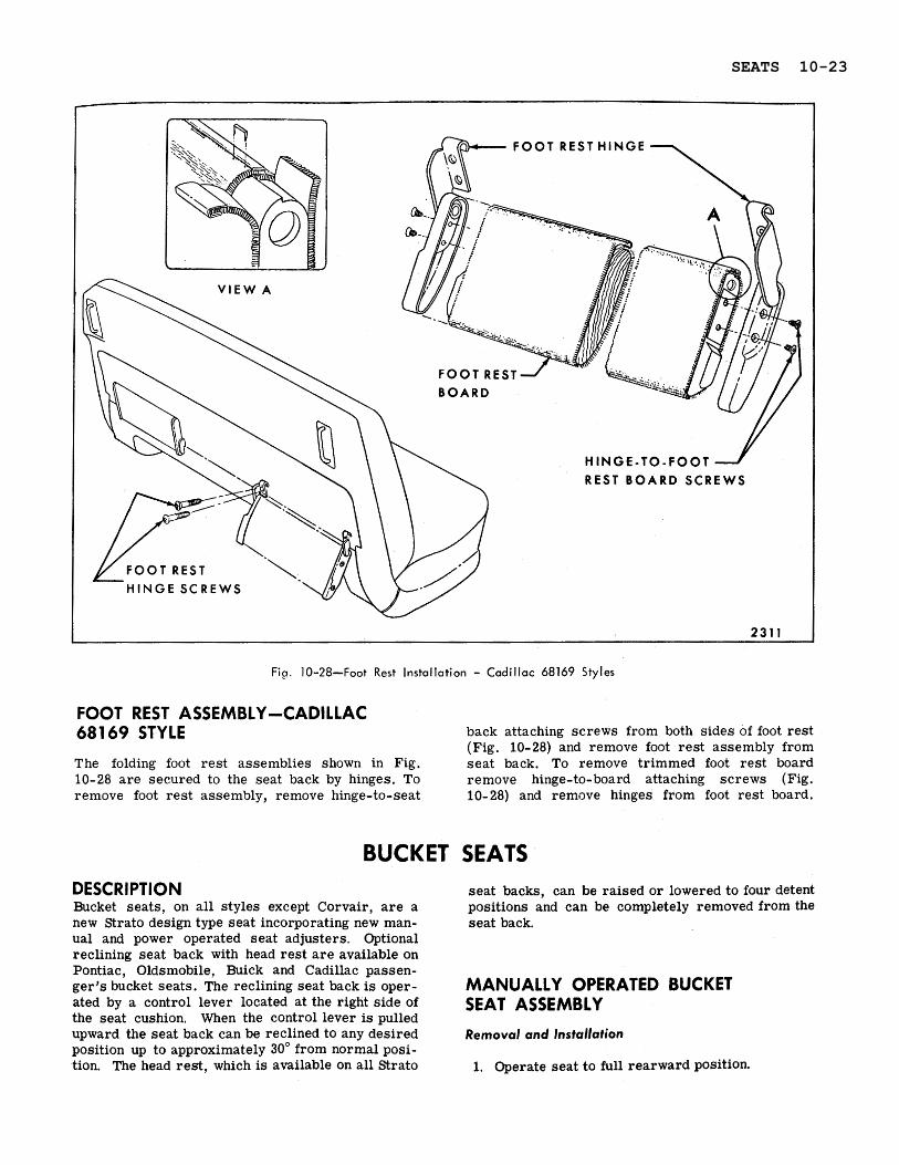
FOOT REST ASSEMBLY -CADILLAC 681 69 STYLE back attaching screws from both sides of foot rest
(Fig. 10-28) and remove foot rest assembly from The folding foot rest assemblies shown in Fig. seat back. To remove trimmed foot rest board 10-28 are secured to the seat back by hinges. To remove hinge-to-board attaching screws (Fig. remove foot rest assembly, remove hinge-to-seat 10-28) and remove hinges from foot rest board.
BUCKET SEATS DESCRlPTlON seat backs, can be raised or lowered to four detent Bucket seats, on all styles except Corvair, a r e a positions and can be completely removed from the new Strato design type seat incorporating new man- seat back. ual and power operated seat adjusters. Optional reclining seat back with head rest a re available on - Pontiac, Oldsmobile, Buick and Cadillac passen- ger's bucket seats. The reclining seat back is oper- MANUALLY OPERATED BUCKET ated by a control lever located at the right side of the seat cushion. When the control lever is pulled
SEAT ASSEMBLY
upward the seat back can be reclined to any desired Removal and Installation position up to approximately 30' from normal posi- tion. The head rest, which is available on all Strato 1. Operate seat to full rearward position.
SEATS 10-23
C A R P E T R E T A I N E R 2210
Fig. 10-29-Bucket Seat Floor Rear Attachment - "A" Styles
2. Turn back floor carpeting sufficiently to expose seat adjuster-to-floor pan attaching nuts o r bolts (Fig. 10-29 o r 10-30).
3. a. On "A, X & Z)) body styles loosen adjuster- to-floor pan front attaching bolts (Fig. 10-29). Operate seat to full forward posi- tion. Remove adjuster-to-floor pan r ea r attaching bolts, then, slide seat rearward sufficiently to disengage front legs of ad- justers from under front attaching bolts and remove seat assembly from body.
b. On "B, C & E" body styles remove adjuster-to-floor pan front attaching bolts (Fig. 10-30). Operate seat to full forward position. Remove adjuster- to- floor pan r ea r attaching bolts and remove seat assembly from body.
4. To install, reverse removal procedure. On "A, X & Z" body styles make sure front leg of both adjusters a r e engaged under front attaching bolts prior to installing rear attaching nuts. Check operation of seat adjus- t e r s to full limits of travel.
POWER OPERATED HORIZONTAL OR FOUR-WAY BUCKET SEAT ASSEMBLY
The two-way and four-way (tilt) seat adjusters a r e actuated by a 12 volt, reversible shunt wound motor with a built-in circuit breaker.
The four-way seat adjuster operating mechanism incorporates a transmission assembly which in- cludes two solenoids and two drive cables leading to the seat adjusters. One solenoid controls the ver- tical movement of the seat while the other solenoid controls the horizontal movement of the seat. When the control switch is actuated, the motor drives the
transmission by means of a belt and one of the transmission solenoids a r e energized simultane- ously. The solenoid plunger then engages with the driving gear dog. The driving gear rotates the drive cables and operates both adjusters. When the adjusters reach their limit of travel, the drive cables stop their rotating action and torque is absorbed by the rubber belt connecting the motor and transmission. When the switch contacts a r e opened, a return spring returns the solenoid plunger to i t s original position disengaging it from the driving gear dog.
Removal and Installation
1. Operate seat .to full forward position. On four- way power seats operate seat to full up posi- tion. Remove seat cushion side panels, where present. Where seat adjuster track covers a r e present, carefully pry out track cover snap-on retainers with a flat-bladed tool and remove track covers.
2. Where necessary, remove sill plates and turn back floor carpeting to expose seat adjuster- to-floor pan attaching nuts and bolts.
3. Remove seat adjuster-to-floor pan r e a r at- taching bolts (Fig. 10-29 o r 10-31); then, operate seat assembly to full rearward position.
4. a. On "A)) Body Styles with power operated four-way seat adjusters loosen adjuster-to- floor pan front attaching bolts (Fig. 10-29), then, slide seat assembly rearward until front legs of adjusters a r e disengaged from under front attaching bolts. Tilt seat rea r - ward sufficiently to disconnect seat harness feed connector and detach harness from clip
on floor pan (Fig. 10- 32); then remove seat assembly from body.
b. On "B, C & E" Styles with power operated seat a d j u s t e r s remove seat adjuster-to- floor pan front attaching bolts (Fig. 10- 31). Tilt seat rearward sufficiently to disconnect seat harness feed connector and detach harness from clip on floor pan (Fig. 10-32 o r 10-33); then remove seat assembly from body.
5. To install, reverse removal procedure. Make sure ground wire is secured ' under adjuster inboard rear attaching nut o r bolt.
On "A" Body Styles make sure adjusters a re properly engaged under front attaching bolts and that r e a r floor carpet is properly posi- tioned around rear supports of adjuster prior to installing carpet retainer on adjuster stud and adjuster r e a r attaching nuts.
MANUALLY OPERATED BUCKET SEAT ADJUSTER
Fig. 10-32-Four-Way Strato Bucket Seat Wiring - Removal and Installation "A & €3" Styles
1. Control Switch 7. Transmission and 1. Remove bucket seat assembly, a s previously 2. Motor Control Relay Solenoid Assembly described, and place seat upside down on a 3. Motor 8. Vertical Control protected surface. 4. Harness Feed Cable (Orange)
Connector 9. Horizontal Control 5. Feed to Passenger Seat Cable (Black) 2. If replacing inboard adjuster, remove assist 6. Pulley Cover Plate 10. Ground Wire spring (Fig. 10- 34).
3. Operate adjuster so that both front and rear adjuster- to- seat frame attaching bolts (Fig.
POWER OPERATED FOUR-WAY 10- 34) are accessible; then, remove attaching BUCKET SEAT ADJUSTER bolts and remove adjuster from seat assembly. Removal and Installation
4. To install, reverse removal procedure.
POWER OPERATED HORIZONTAL BUCKET SEAT ADJUSTER
Removal and Installation
1. Operate seat to a midway horizontal position. Remove bucket seat assembly, a s previously described, and place seat upside down on a clean protected surface.
2. Disconnect power drive cable from adjuster gearnut (Fig. 10- 3 5).
3. Remove adjuster-to-seat bottom frame front and rear attaching bolts (Fig. 10-35) and re- move adjuster from seat assembly.
4. To install, reverse removal procedure. Where spacers were installed between seat adjuster and floor pan or seat adjuster and seat frame make certain spacers are reinstalled. Check for proper operation of seat to full limits of travel.
1. Operate seat to assembly to fully raised and midway horizontal positions.
ADJUSTER HO-RIZONTAJ
2206 C
Fig. 1 0-36-Four-Way Bucket Seat Assembly
10-26 SEATS
Fig. 10-37-Four-Way Bucket Seat Adjusters
1. Motor and Transmission 7. Electric Motor Relay Drive Belt Cover and 8. Motor and Transmission Attaching Screws Support
2. Transmission Drive Pulley 9. Motor and Transmission 3. Transmission and Motor Support-to-Right
Drive Belt Adjuster Attaching N u t 4. Motor Drive Pulley 10. Motor and Transmission 5. Transmission Assembly Support-to-Left 6. Electric Motor Assembly Adjuster Attaching Nuts
1 1. Adjuster Horizontal Drive Cable
1 2. Adjuster Vertical Drive Cable
13. Adjuster Torque Tube 14. Adjuster Vertical Gearnu t
2. Remove front seat assembly from body with 6. Carefully disengage adjuster from support, and attached adjusters, motor and transmission, torque tube; then, remove adjuster from seat. a s previously described, and place upside down on a clean protected surface.
7. To install power operated four- way bucket seat adjuster assembly, reverse removal proce-
3. If outboard adjuster is being removed, dis- dure. Check for proper operation of seat ad- connect bolt, horizontal and vertical drive justers to limits of travel. cables from vertical gearnut and horizontal actuator (Fig. 10- 36).
4. Remove nuts securing motor and transmission POWER OPERATED FOUR-WAY BUCKET support to adjuster being removed (Fig, 10- 37). SEAT ADJUSTER MAJOR COMPONENTS
The following service procedures cover replace- 5. Remove adjuster-to-seat bottom frame front ment of the major component par ts of the power
and r ea r attaching bolts securing adjuster to operated four-way seat adjuster, used on bucket be removed (Fig. 10-36). seats.
SEATS 10-27
Fig. 10-38-Four-Way Bucket Seat Transmission
- GEAR HOUSING DRIVING GEAR HARNESS SOLENOID
CONNECTOR
4
4
4
SOLENOlDS AND SOLENOID ,,,, PULLEY DOG SPRING D O G SHAFT COVER PLATE HOUSING
Motor and Transmission Drive Belt and Pulleys Transmission Assembly and Horizontal and Vertical Drive Cables
h
Removal and Installation Removal and Installation
1. At front of seat motor and transmission drive belt cover remove attaching screws (Fig. 10-37) and remove cover.
2. Remove drive belt (Fig. 10-37) from both motor and transmission drive pulleys. Pulleys may be removed from either motor o r trans- mission by pulling pulleys off their respective shaft.
3. To install drive belt, reverse removal proce- dure. Check for proper operation of seats to full limits of travel.
Motor Assembly
Removal and lnstallation
1. If motor can be operated, operate seat assem- bly to full "up" position. Disconnect wire harness connector from motor relay.
2. Remove motor - to- transmission drive belt cov- e r and drive belt, a s previously described.
3. From under motor and transmission support remove two cap screws securing motor to motor-and-transmission support and remove motor assembly from under seat.
4. To install, reverse removal procedure. Check for proper operation of seat to full limits of travel.
1. Remove front seat assembly from body with attached adjusters, motor and transmission, as previously described, and place upside down on a protected surface.
2. Disconnect wire h a r n e s s connector from transmission.
3. Remove motor and transmission drive belt cover and remove drive belt (Fig. 10-37).
4. Remove two screws securing transmission as - sembly to motor and transmission support; then, move transmission forward to disengage from drive cables and remove transmission from seat.
NOTE: To remove horizontal o r vertical drive cables detach drive cable from adjuster and remove cable.
Disassembly and Assembly of Transmission
1. Remove front seat adjuster transmission from seat assembly.
2. Remove screws securing gear and solenoid housings together; then, carefully separate housings and remove component parts of trans- mission assembly (Fig. 10-38).
3. To assemble transmission, reverse removal procedure.
10-28 SEATS
IMPORTANT: Prior to o r during installation, lubricate frictional surfaces of driving gear thrust washer, gears, dog washers, shaft and solenoid plungers with "Lubriplate" (630AAW) o r equivalent.
4. To install transmission assembly, reverse re - moval procedure. Make certain drive cables a r e properly engaged in transmission and properly retained in cut out notches sf motor and transmission support prior to installing transmission attaching screws.
5. Check for proper operation of seat to full limits of travel,
Adjuster Vertical Gearnut
Removal and lnstallation
1. Operate seat assembly to fully raised and mid- way horizontal position.
2. Remove front seat assembly from body and place upside down on a clean protected surface.
3. Using a clutch type screwdriver o r other suitable tool, remove shoulder screws securing linkage to vertical gearnut (Fig. 10- 37).
4. Remove jackscrew "down" stop from jack- screw (Fig. 10-37).
5. Using a portable power source to energize the motor, actuate vertical gearnut until gearnut is disengaged from jackscrew.
NOTE: It may be necessary to manually ra ise o r lower upper r e a r portion of adjuster to gain clearance for removal of gearnut.
6. Disconnect drive cable from gearnut.
7. To install, reverse removal procedure. Check seat adjusters for proper operation.
Adiuster Jackscrew
Removal and lnstallation
1. Remove adjuster gearnut a s p r e v i o u s 1 y described.
2. Remove seat adjuster-to- seat bottom frame front and r e a r attaching bolts.
3. As a bench operation, remove jackscrew-to- adjuster linkage attaching rivet and remove jackscrew from adjuster assembly (Fig. 10- 37).
NOTE: It may be necessary to manually raise o r lower upper r e a r portion of adjuster to gain access to jackscrew attaching rivet.
4. To install, reverse removal procedure. Use new rivet to attach jackscrew- to- adjuster link- age. Check seat adjusters for proper operation,
Adjuster Horizontal Actuator Assembly
Removal and lnstallation
1. Remove front seat assembly from body a s previously described and place upside down on a clean protected surface.
2. Using a clutch type screwdriver o r other suit- able tool, remove shoulder screws securing linkage to vertical gearnut (Fig. 10- 37).
3. Using a portable power source, actuate vertical gearnut until gearnut is against "down" stop on jackscrew assembly.
4. Disconnect drive cable from horizontal actua- tor assembly.
5. Remove screws securing horizontal actuator assembly to adjuster lower track; then remove actuator from adjuster assembly (Fig. 10-37).
6. To install, reverse removal procedure.
NOTE: When installing horizontal actuator, adjuster acturator so that drive gear is fully engaged with teeth on lower channel. When horizontal actuator attaching screws a r e tight - ened, there should be no free motion between upper and lower channels. Re- adjust actuator "as required" until all f ree motion between channels has been removed. Check seat ad- justers for proper operation.
Torque Tube Assembly
Removal and lnstallation
1. Remove inboard seat adjuster assembly, a s previously described.
2. Disengage torque tube from outboard adjuster (Fig. 10- 36 and 10- 37) and remove torque tube assembly.
3. To install torque tube assembly, reverse re- moval procedure. Check for proper operation of seat to full limits of travel.
SEATS 10-29
Fig. 10-39-Bucket Seat Back Removal (Without
Reclining Seat Back) A l l Except Corvair
STANDARD BUCKET SEAT BACK ASSEMBLY-ALL TWO DOOR STYLES EXCEPT CORVAIR Removal and lnstallation
1. Remove bucket seat assembly from body, a s previously described, and place on a clean protected surface.
2. Remove hog rings at both sides of seat secur- ing cushion side t r im at r e a r of .seat and fold t r im forward sufficiently to expose four seat back attaching bolts (Fig. 10- 39).
T E R HINGE ARM
WASHER 1600
Fig. 10-40-Bucket Seat Back Removal - Corvair
3. Remove seat back attaching bolts at both sides of seat and remove side panel support and seat back assembly from seat cushion assembly.
4. To install seat back assembly, reverse re- moval procedure. Make certain seat side panel support is secured under seat back outer at- taching bolts.
STANDARD BUCKET SEAT BACK ASSEMBLY C O R V A I R Removal and Installation
1. Using a flat-bladed tool, carefully remove retainer from inner and outer hinge pin (Fig. 10-40).
NOTE: On 10000 Series, remove screw secur- ing hinge a r m cover (Fig. 10-41) and remove cover; then, remove inner hinge pin retainer.
2. Carefully disengage inner and outer front seat back hinge a rms from pins; then remove seat back assembly from body.
3. To install, reverse removal procedure. Pr io r to installation of back assembly, be sure inner and outer washers a r e installed over hinge pins. In addition, inspect hinge a r m retainers. If retainers a r e damaged, replace retainers using new parts.
INNER HINGE ARM
INNER HINGE 1651
ARM COVER
Fig. 10-41-Bucket Seat Back Inner "Hinge" Arm- Corvai r
10-30 SEATS
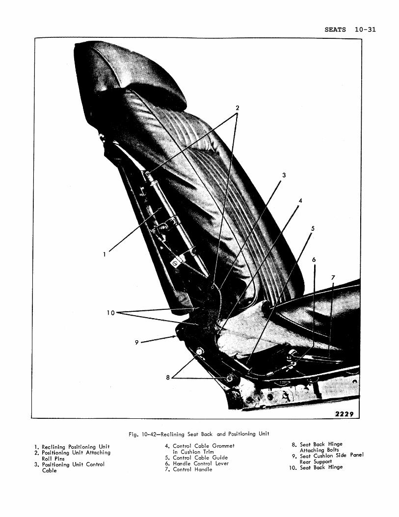
1. Reclining Positioning Uni t 2. Positioning Unit Attaching
Roll Pins 3. Positioning Uni t Control
Cable
Fig. 10-42-Reclining Seat Back and Positioning Unit
4. Control Cable Grommet i n Cushion Trim
5. Control Cable Guide 6. Handle Control Lever 7. Control Handle
8. Seat Back Hinge Attaching Bolts
9. Seat Cushion Side Panel Rear Support
10. Seat Back Hinge
SEATS 10-31
RECLINING FRONT SEAT BACK AND HEADREST
RECLINING FRONT SEAT BACK (PASSENGER SIDE)-"STRATO" FULL WIDTH OR BUCKET SEAT
Description
The reclining seat back which is available on the passenger seat of the Strato design front seats can be reclined approximately 30 degrees from the normal seat back position. The reclining unit is a friction operating mechanism and is actuated by a control handle and cable at the right side of the seat.
When the control handle is pulled upward the con- t rol cable unlocks the reclining positioning unit in the seat back allowing the seat back to be reclined, by means of rearward pressure on the seat back, to a maximum of approximately 30 degrees o r until the control handle is released. When the control handle is released the reclining positioning unit is locked and will not allow the seat back to be re- clined further. When the control handle i s pulled up and there i s no rearward pressure on the seat back, the assist spring in the reclining positioning unit will return the seat to the normal position o r to a position at which the handle is released. The friction mechanism of the positioning unit will allow the seat back to be moved forward to the normal position with approximately four pounds manual forward push at the top of the seat back. This "dress-up)) feature allows the driver o r passenger to return a reclined seat back to i t s normal position without having to operate the con- t ro l handle.
Reclining Seat Back Assembly
Removal and Installation
1. Remove seat assembly from body, a s de- scribed, and place upside down on a clean protected surface.
2. On right side of seat with seat side panel re- moved, remove hog rings securing cushion side t r im at r e a r of seat and along bottom of seat and turn back t r im sufficiently to expose seat back attaching bolts and reclining control cable attachment a t handle control lever (Fig. 10-42).
3. Detach reclining positioning unit control cable from handle control lever; then pull control cable through cable guide and through grommet in cushion t r im (Fig. 10-42).
4. a. On reclining bucket seat remove hog rings securing cushion side t r im facing on in-
board side of seat and turn t r im forward sufficiently to expose seat back attaching bolts. Then remove seat back attaching bolts from both sides of seat and remove seat back assembly from seat.
b. On reclining full width seat, remove screw at inboard side of seat back securing seat back attaching bolt cover plate and remove cover plate. Remove seat back inner at- taching bolts then, remove seat back outer attaching bolts and remove seat back as - sembly from seat.
5. To install seat back assembly, reverse re - moval procedure. Make certain side panel support (Fig. 10-42) is secured under seat back outer attaching bolts.
Reclining Seat Back Positioning Unit
Removal and Installation
1. Remove seat assembly from body, a s pre- viously described, and place upside down on a clean protected surface.
2. On right side of seat with seat side panel re - moved, removed hog rings securing cushion side t r im at rea r of seat and along bottom of seat and turn back t r im sufficiently to expose reclining control cable attachment at handle control lever (Fig. 10-42).
3. Remove two screws securing bottom of seat back panel to seat back; then, lift panel upward to disengage from upper retainers and remove panel from seat back (Fig. 10-43).
4. Remove hog rings securing right side of seat back side t r im to seat back frame (Fig. 10-43) and turn t r im forward sufficiently to expose positioning unit (Fig. 10- 42).
5. Detach reclining positioning unit control cable from handle control lever; then pull control cable through cable guide and through grommet in cushion t r im (Fig. 10-42).
6. Using a suitable size drift punch carefully drive out roll pins securing positioning unit to support on seat back frame and to seat back hinge (Fig. 10-42); then remove positioning unit from seat back.
IMPORTANT: If roll pins do not drive out easily use a suitable back up to prevent pos- sible damage o r breakage of the positioning unit o r mounting brackets.
10-32 SEATS
SEAT B A C K
Fig. 10-43-Strato Seat Back Panel and Headrest
Where necessary, remove control cable from positioning unit.
7. To install reclining seat back positioning unit, reverse removal procedure. Check for proper operation of reclining seat back to full limits of travel.
STRATO SEAT BACK HEADREST
Description
All reclining seat backs a r e equipped with a head- res t which is adjustable to four different positions. This headrest is also available a s an option on al l Strato design seats on either the dr ivers o r pas- sengers seat back. When desired, the headrest can be removed from the seat back; however, i t re- quires slightly more lifting effort to clear the head- res t past the last detent position.
Strato Seat Back Headrest Support Guide Tube
Removal and Installation
1. Remove headrest assembly from seat back.
2. Remove support finishing escutcheon screw and remove escutcheon (Fig. 10-44).
3. Carefully pull plastic support guide tube out of support. If guide tube hangs up on detent spring insert a screwdriver into guide and depress detent spring sufficiently to remove guide tube.
4. To install support guide tube reverse removal procedure. Make certain lower end of plastic guide i s inserted into hole in bottom of support and that cut out in guide for detent spring is facing rearward (Fig. 10-44). Check for proper operation of headrest.
Strato Seat Back Headrest Supports
Removal and Installation
1. Remove headrest assembly from seat back.
2. Remove two screws securing bottom of seat back panel; then, lift panel upward to dis- engage from upper retainers and remove panel from seat back (Fig. 10-43).
3. Remove headrest support finishing escutcheon screw and remove escutcheon (Fig. 10-44).
4. Remove four remaining support attaching screws (Fig. 10-44) and remove support from seat back. Where required, remove support guide from support.
5. To install headrest support, reverse removal procedure. Make certain lower end of plastic guide i s inserted into hole in bottom of support and that cut out in guide for detent spring is facing rearward (Fig. 10-44). Pr io r to tight- ening support attaching screws, install head- res t into supports and align support(s) with headrest arm(s); then, tighten support screws.
6. Check for proper operation of headrest.
SUPPORT FINISHING ESCUTCHEON AND SCREW
SECTION A-A
SCREWS 2 2 4 8
Fig. 10-44-Strato Seat Back Head Rest Support
SEATS 10-33
REAR SEAT
REAR SEAT CUSHION-ALL STYLES
Removal
1. Push lower forward edge of cushion rearward .and pull cushion upward until wire protrusions on seat bottom frame disengage from floor pan retainers a t each side of seat.
NOTE: On "E" ~ o d y Styles lift up front of seat cushion sharply to disengage cushion from pan retainers.
2. Pull cushion forward and carefully remove from body.
Installation
1; Carefully lift cushion into body using caution not to damage adjacent trim.
2. Position r ea r edge of cushion under rea r seat back assembly.
3. Center wire protrusions on seat bottom with retainers on or in floor pan.
IMPORTANT: If seat bottom frame protru- sions a r e not properly centered in relation to retainers on floor pan, proper engagement and placement of cushion will be extremely difficult.
4. Push forward edge of cushion rearward and downward until protrusions a r e properly en- gaged behind retainers on floor pan.
REAR SEAT BACK ASSEMBLY- ALL STYLES EXCEPT CORVAIR
Removal and Installation
1. Remove r ea r seat cushion assembly.
At bottom of seat back bend out the tabs secur- ing the lower portion of seat back to floor panel. On convertible styles, remove screw from r ea r side of seat back support panel se - curing upper corners of seat back to panel. If screws a r e used securing center of seat back to seat back panel it will be necessary to re- move screws from inside r ea r compartment.
Remove two screws securing lower portion of seat back to floor pan.
3. Pull seat back assembly out a t the bottom until seat back clears body tabs; then, on all styles except "E" Styles raise seat back upward until disengaged from hangers on the seat back panel support. On "E" Styles push seat back downward until wire protrusions at top of seat back a r e disengaged from slots in seat back panel support.
4. Remove seat back assembly from body.
5. To install, reverse removal procedure, making certain that all attaching body tabs and hangers have industrial body tape applied to them to act as an anti- squeak,
REAR SEAT BACK CENTER ARM REST AND CURTAIN
Removal and Installation
1. Lower r ea r seat back a r m rest. On all styles except 68069 carefully pull upper portion of a rm rest curtain out of slot in hanger plate and fold curtain forward. On 68069 Style fold a rm res t flipper forward.
2. Remove four screws securing a r m rest to hanger plate linkage then, remove a r m res t from seat back.
3. To install, reverse removal procedure.
REAR SEAT BACK CENTER ARM REST HANGER PLATE AND LINKAGE
Removal and Installation
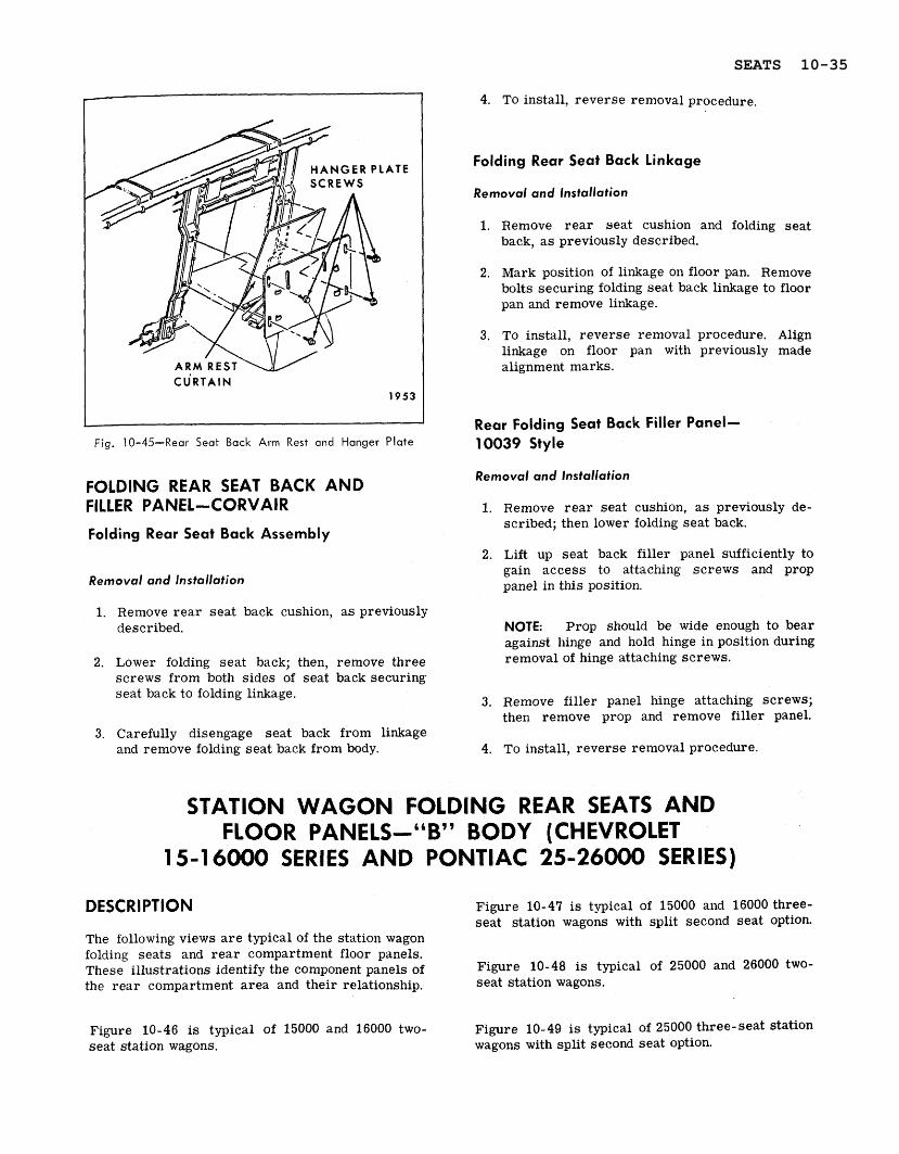
1. Remove r ea r seat back center a r m rest; then, remove two screws securing a rm rest hanger plate to body seat back support brace. Remove rear seat back.
2. On back side of r e a r seat back, remove four screws securing a rm res t hanger plate to seat back supports; then, carefully remove a r m res t and hanger plate assembly from seat back (Fig. 10-45).
3, To install, reverse removal procedure. Pr io r to tightening hanger plate screws move a r m rest assembly upward until top is snug against top of opening in seat back.
10-34 SEATS
Fig. 10-45-Rear Seat Back Arm Rest and Hanger Plate
FOLDING REAR SEAT BACK AND FILLER PANEL-CORVAIR
Folding Rear Seat Back Assembly
Removal and Installation
1. Remove r ea r seat back cushion, as previously described.
2. Lower folding seat back; then, remove three screws from both sides of seat back securing seat back to folding linkage.
3. Carefully disengage seat back from linkage and remove folding seat back from body.
4. To install, reverse removal procedure.
Folding Rear Seat Back Linkage
Removal and lnstallation
1. Remove r ea r seat cushion and folding seat back, a s previously described.
2. Mark position of linkage on floor pan. Remove bolts securing folding seat back linkage to floor pan and remove linkage.
3. To install, reverse removal procedure. Align linkage on floor pan with previously made alignment marks.
Rear Folding Seat Back Filler Panel- 10039 Style
Removal and lnstallation
1. Remove r ea r seat cushion, a s previously de- scribed; then lower folding seat back.
2. Lift up seat back filler panel sufficiently to gain access to attaching screws and prop panel in this position.
NOTE: Prop should be wide enough to bear against hinge and hold hinge in position during removal of hinge attaching screws.
3. Remove filler panel hinge attaching screws; then remove prop and remove filler panel.
4. To install, reverse removal procedure.
STATION WAGON FOLDING REAR SEATS AND FLOOR PANELS-"B" BODY (CHEVROLET
1 5-1 6000 SERIES AND PONTIAC 25-26000 SERIES)
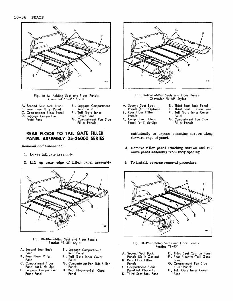
DESCRIPTION Figure 10-47 is typical of 15000 and 16000 three- seat station wagons with split second seat option.
The following views a r e typical of the station wagon folding seats and r ea r compartment floor panels. These illustrations identify the component panels of Figure 10-48 i s typical of 25000 and 26000 two- the rea r compartment a rea and their relationship. seat station wagons.
Figure 10-46 is typical of 15000 and 16000 two- Figure 10-49 is typical of 25000 three-seat station seat station wagons. wagons with split second seat option.
SEATS 10-35
Fig. 10-46-Folding Seat and Floor Panels Chevrolet "B-35" Styles
A. Second Seat Back Panel E . Luggage Compartment B . Rear Floor F i l ler Panel Rear Panel C. Compartment Floor Panel F . Tail Gate lnner D. Luggage Compartment Cover Panel
Front Panel G. Compartment Pan Side F i l ler Panels
REAR FLOOR TO TAIL G A T E FILLER PANEL ASSEMBLY 25-26000 SERIES
Removal and Installation-
1. Lower tail gate assembly.
2. Lift up rear edge of filler panel assembly
Fig. 10-48-Folding Seat and Floor Panels Pontiac "8-35" Styles
A. Second Seat Back E . Luggage Compartment Panel Rear Panel
B . Rear Floor Filler F . Tail Gate Inner Cover Panel Panel
C. Compartment Floor G. Compartment Pan Side Filler Panel (at Kick-Up) Panels
D. Luggage Compartment H . Rear Floor-to-Tai l Gate Front Panel Panel
Fig 10-47-Folding Seats and Floor Panels Chevrolet "B-45" Styles
A. Second Seat Back D, Third Seat Back Panel Panels (Split Option) E . Third Seat Cushion Panel
B. Rear Floor Filler F . Tail Gate Inner Cover Panels Panel
C. Cornpartmen t Floor G. Compartment Pan Side Panel (at Kick-Up) Filler Panels
sufficiently to expose attaching screws along forward edge of panel.
3. Remove filler panel attaching screws and re- move panel assembly from body opening.
4. To install, reverse removal procedure.
Fig. 10-49-Folding Seats and Floor Panels Pontiac "B-45"
A. Second Seat Back E . Third Seat Cushion Panel Panels (Split Option) .F . Rear Floor-to-Tail Gate
B . Rear Floor Fi l ler Panel Panels G. Compartment Pan Side
C. Compartment Floor Filler Panels Panel (at Kick-Up) H . Tail Gate Inner Cover
D. Third Seat Back Panel Panel
10-36 SEATS
L U G G A G E COMP ARE TIRE WELL
Fig. 10-50-Rear Com part men t Pan Side F i l ler Panels
COMPARTMENT PAN SIDE FILLER PANEL (RIGHT OR LEFT SIDE) ALL STYLES Removal and Installation:
1. On "35" Styles, use handle and fold r ea r lug- gage compartment panel forward until i t is resting entirely on front luggage compartment panel (Fig. 10- 50).
2. On "45" Styles, ra ise folding 3rd seat back assembly to up position; then raise 3rd seat bottom cushion assembly to up o r "sittingJJ position.
3. For right floor side panel, remove spare t i re cover panel.
4. On left side, remove screw which secures floor side panel to panel support.
5. Along inboard and outboard side facing of right and/or left panel, remove screws which secure panel to panel supports (Fig. 10-50) and re- move panel(s) from body.
6. To install, reverse removal procedure. If installing new filler panel, apply cloth body tape over a l l screw attaching holes. (See Fig. 10- 50).
LUGGAGE COMPARTMENT FRONT AND REAR PANEL ASSEMBLIES TWO-SEAT STYLES
Removal and lnstallation
1. Using handle, fold r e a r luggage compartment panel forward until i t is resting entirely on front luggage compartment panel.
2. Fold combined front and rear luggage com- partment panels to "up" or half open position. (See Fig. 10- 50).
3. Remove bolt (Fig. 10- 51) a t both sides of front panel securing front and rear panel assemblies to supports; then remove assembly from body.
4. To install, reverse removal procedure. Make sure bushing and spring washer a r e properly installed (Fig. 10- 51).
NOTE: When replacing front luggage compart- ment panel with new part, transfer r e a r lug- gage compartment panel with attached hinge to new part.
1. Using handle, fold r e a r luggage compartment panel forward until i t is resting entirely on front luggage compartment panel.
2. Remove screws securing hinge assembly to r e a r luggage compartment panel and remove panel assembly from body.
3. To install, reverse removal procedure.
PRlNG WASHER
Fig. 10-51 -Luggage Compartment Panel Attachment to Body
SEATS 10-37
wkv' S U P P O R T BO
I I I
Fig. 10-52-Folding Third Seat Cushion
LUGGAGE COMPARTMENT FRONT AND REAR PANEL HINGE ASSEMBLY
Removal and Installation
1. Using handle, fold rea r luggage compartment panel forward until it is resting entirely on front luggage compartment panel.
2. Remove screws securing hinge assembly to both front and rear panels and remove hinge from body.
3. To install, reverse removal procedure.
FOLDING THIRD SEAT CUSHION THREE-SEAT STYLES
Removal and lnstallation
1. Lift third seat cushion to a half raised position o r approximately vertical to floor pan (Fig. 10- 52).
2. Remove four seat cushion screws from rear - ward edge of cushion (Fig. 10-52).
3. Pull rea r edge of cushion away from flange of cushion panel then lift cushion upward to disengage cushion border wire from four tabs on panel. Remove cushion from body and place on a clean protected surface.
4. To install, reverse removal procedure. Make sure cushion border wire is engaged with all four panel tabs prior, to installing cushion,at- taching screws.
FOLDING THIRD SEAT CUSHION, PANEL ASSEMBLY AND SUPPORT THREE-SEAT STYLES
Removal and lnstallation
1. Lift third s e a t cushion to a half raised position o r approximately vertical to floor pan. (See Fig. 10-52).
2. Remove two bolts a t each side of seat securing supports to body (Fig. 10-52); then, remove seat cushion, panel assembly and supports from body and place on a clean protected surface.
To remove support, remove cushion from panel assembly; then remove bolt securing support to cushion (Fig. 10- 53).
3. To install, reverse removal procedure. If support was removed from seat cushion panel, make sure bushing and spring washer a r e properly installed. (See Fig. 10- 53).
FOLDING THIRD SEAT BACK TRIM ASSEMBLY THREE-SEAT STYLES
Removal and lnstallation
1. Raise third seat back assembly - leave cushion assembly in down position.
2, Remove four screws securing lower edge of seat back t r im to seat back panel. (See Fig- 10- 54).
3. Pull lower edge of seat back t r im slightly rearward; then, lift t r im assembly upward to disengage t r im border wire from four tabs on
Fig. 10-53-Third Seat Cushion Panel and Support
10-38 SEATS
SEAT BACK SU
Fig. 10-54-Folding Third Seat Back
upper portion of panel. Remove t r im assembly from body and place on a clean protected surface.
4. To install, reverse removal procedure. Make sure seat back t r im border wire is engaged with all four panel tabs a t upper portion of panel pr ior to installing seat back t r im at- taching screws.
FOLDING THIRD SEAT BACK PANEL ASSEMBLY THREE-SEAT STYLES
Removal and lnstallation
1. Remove third seat back t r im assembly
2. At both sides of third seat back panel remove seat back linkage bolt (Fig. 10-55) and bolt securing seat back panel to support (Fig. 10- 55); then remove seat back panel assembly from body.
3. To install, reverse removal procedure.
COMPARTMENT FLOOR PANEL ASSEMBLY (AT KICK-UP) ALL STYLES
Removal and Installation
1. On "45" Styles, remove folding 3rd seat back assembly a s previously described.
2. On "35" Styles, remove luggage compartment front and r ea r panel assemblies (complete) as previously described.
3. Directly under r e a r edge of compartment floor panel remove four screws securing panel to floor pan.
4. At front of compartment floor panel remove five screws securing panel to floor pan; then, remove compartment floor panel from body.
5. To install, reverse removal procedure.
REAR FLOOR FILLER PANEL ALL STYLES
Removal and Installation
1. Remove compartment floor panel assembly (at kick-up) a s previously described.
2. Along r ea r edge of fi l ler panel, remove screws which secure panel to floor pan.
3. Fold filler panel forward sufficiently to remove screws which secure panel to folding 2nd seat back assembly and remove filler panel from body.
4. To install, reverse removal procedure.
SECOND SEAT CUSHION (FULL WIDTH OR SPLIT SEAT) ALL STYLES
Removal and Installation
1. Lift up front edge of folding r ea r seat cushion assembly to disengage seat bottom frame from slots in r e a r seat support on floor pan; then, remove cushion assembly from body and place on a clean protected surface,
2. To install, reverse removal procedure. Make certain that seat cushion frame is fully engaged in supports on floor pan.
SPRING WASHER
B O L T 1909
Fig. 10-55-Third Seat Back Panel and Linkage
SEATS 10-39
FOLDING SECOND SEAT BACK TRIM ASSEMBLY [FULL WIDTH OR SPLIT SEAT) ALL STYLES
Removal and lnstallation
1. Raise folding second seat back and remove second seat cushion.
2. On underside of second seat back panel, re- move screws securing seat back t r im assem- bly to seat back panel.
NOTE: Do not remove screws securing rear floor filler panel hinge to second seat back panel.
3. Pull lower edge of seat back t r im slightly forward; then lift t r im assembly upward to dis- engage t r im border wire from tabs on upper portion of panel. Remove t r im assembly from body and place on a clean protected surface.
4. To install, reverse removal procedure. Make sure seat back t r im border wire is engaged with panel tabs at upper portion of seat back panel prior to installing seat back t r im attach- ing screws.
FOLDING SECOND SEAT BACK TRIM, PANEL AND LINKAGE ASSEMBLY (FULL WIDTH OR SPLIT SEAT) ALL STYLES
Removal and lnstallation
1. Raise folding second seat back and remove second seat cushion.
E R SCREWS
Fig. 10-56-Folding Second Seat Back Supports
(Full Width Seat)
2. On underside of folding second seat back re- move screws securing rear floor filler panel hinge to seat back panel.
NOTE: Do :lot remove screws securing seat back t r im assembly to seat back panel.
3. Mark position of folding second seat back linkage supports on floor pan. Remove nuts from both sides of seat back securing linkage supports to floor pan (See Figure 10-56), full width seat (Fig, 10- 57) for split seat.
Lift seat back assembly with attached linkage from body and place on a clean protected surface.
4. To remove linkage from folding second seat back remove linkage-to- seat back panel attach- ing bolts and remove linkage - See (Fig. 10- 58 for full width seat) (Fig. 10- 59 for split seat).
5. To install, reverse removal procedure. If linkage was removed from split seat back, make sure bushings and spring washers a r e properly installed prior to installing linkage attaching bolts. (See Fig. 10- 59).
L E F T SEAT BACK INNER LINKAGE 4 ' n
INNER SUPPORT
Fig. 10-57-Folding Second Seat Back Supports and
Linkages (Split Seat)
10-40 SEATS
FOLDING SECOND SEAT BACK LINKAGE ASSEMBLY (FULL WIDTH SEAT-RIGHT OR LEFT SIDE SPLIT SEAT- OUTER LINKAGE ONLY) ALL STYLES 1f both right and left linkage assemblies a r e to be
on full width second seat remove second seat back t r im, panel and linkage assembly and. remove linkage from seat back panel a s described under "Folding Second Seat Back Trim, Panel and Linkage Assembly - Removal and Installation".
~f one linkage assembly (right o r left side) is to be removed proceed a s follows:
~ e r n o v d and Installation
1. Remove second seat cushion.
2. Move folding second seat back forward just sufficiently to remove two lower linkage-to- seat back panel attaching screws. (See Fig, 10- 58).
3. Carefully return seat back to full up position; then, place a support under seat back assembly to support seat back in this position.
4. Remove two upper linkage-to-seat back panel attaching screws. (See Fig. 10- 58).
5. Remove nuts securing linkage support to floor pan (See Fig. 10-56); then carefully remove linkage assembly from seat back and floor pan.
6 . To install, reverse removal procedure.
FOLDING SECOND SPLIT SEAT BACK INNER LINKAGE ASSEMBLY ALL STYLES
L I N K A G E - TO - SEAT BACK SCREWS 1912
A
Fig. 10-58-Folding Second Seat Back Supports and
Linkage (Full Width Seats)
5. To install, reverse removal procedure. Make sure bushings and spring washers a r e properly installed prior to installing linkage attaching bolts to both right and left seat back panels. (See Fig. 10- 59).
FOLDING SECOND SEAT BACK CATCH ASSEMBLY ALL 25-26000 STYLES
3, Remove three screws securing catch to seat back frame and remove catch assembly from seat back (Fig. 10- 60).
Removal and Installation 4. To install, reverse removal procedure.
1. Remove left second seat cushion and place left seat back in full up position. Place a support under right side of left seat back to support seat back in this position.
2. Place right seat back in partially down posi- tion (resting on seat cushion).
3. Remove nuts securing inner linkage assembly to floor pan (See Fig. 10-57).
4. Remove inner linkage-to-seat back bolts from both right and left seats (See Fig. 10-59); then carefully disengage inner linkage from seat backs and floor pan studs and remove linkage assembly.
LEFT SEAT BACK LINKAGE
E
RIGHT SEAT BACK LINKAGE 1913
Fig. 10-59-Folding Second Seat Back Inner Linkage
and Support
SEATS 10-41
5TRlKER BAR I O N B O D Y )
1 b\ i CATCH' dL--, M A X . 114
1 1 M I N . 118
%2e.x CATCH ADJUSTMENT
CATCH ASSEMBLY SCREWS 1921 (
Fig. 10-60-Folding Seat Back Catch - All Pontiac "B" Styles
ESCUTCHEON
CYLINDER A N D CASE
ESCUTCHEON
L U G G A G E
CATCH REAR PANEL
CYLINDER CASE RETAINER
\ - -
SCREW
IMPORTANT: To assure proper operation of the folding second seat back the catch assembly should be installed and, where necessary, ad- justed for a minimun gap of 1/64 inch to a maximum gap of 3/16 inch between bottom of slot in catch and catch s t r iker when seat back is in full "up" position (Fig. 10- 60).
2. On underside of luggage compartment r e a r panel remove catch retainer and catch from lock cylinder case (Fig. 10-61); then turn lock cylinder with key until cylinder can be removed from case.
Fig. 10-61 -Luggage Compartment Lock Chevrolet "B" Styles 1. Open luggage compartment rea r panel.
10-42 SEATS
2, On underside of luggage compartment r e a r retainer (Fig. 10- 61); then, remove lock cylin- panel, remove catch retainer and catch (Fig. der and case, gasket and escutcheon from panel 10- 61). (Fig. 10- 61).
3. Remove lock cylinder case retainer screw and 4. To install, reverse removal procedure.
STATION WAGON FOLDING SEATS AND FLOOR PANELS-"A" BODY
EXCEPT "65" STYLES
DESCRIPTION
Figures 10-62 and 10-63 a r e typical of two-seat station wagon folding full second seat and rear com- partment floor panels. The illustration identifies component parts, their relationship and various attaching points.
REAR COMPARTMENT FLOOR PANEL COVERING STYLES WlTH RUBBER MAT
A one-piece r ea r compartment floor panel carpet with a pad backing is available a s an option. The carpet is retained at the front and r ea r edges by finishing moldings which a r e secured to the floor panel by screws. (See Fig. 10-63). The sides of the carpet a r e inserted under the r e a r quarter t r im and wheelhouse t r im assemblies.
The rear compartment floor panel conver consists of a one-piece rubber mat with a pad backing. The REAR SEAT CUSHION ASSEMBLY rubber mat is installed loose with sides inserted TWO-SEAT STYLES under rea r quarter t r im a n d wheelhouse t r im assemblies. Removal and Installation
REAR COMPARTMENT FLOOR PANEL I, Lift up front edge of cushion assembly to dis- COVERING STYLES WITH VINYL MAT engage protrusions on seat bottom frame from
slots in seat cushion support and remove The r ea r compartment floor panel covering con- cushion assembly. s is ts of a one-piece vinyl mat with a pad backing. The vinyl mat is installed loose with sides inserted under the r e a r quarter t r im and wheelhouse t r im 2. To install, reverse removal procedure, Make assemblies. The 23535 Style incorporates metal certain protrusions on seat bottom frame a r e skid s t r ips which a r e tabbed to the vinyl mat. fully engaged in slots in seat cushion support.
TAIL GATE INNER COVER PANEL
REAR FLOOR
Fig. 10-62-Folding Second Seat and Rear Floor
Panel Covers
FINISHING MOLDING
Fig. 10-63-Folding Second Seat and Rear Floor Panel Covering
SEATS 10-43
FILLER PANEL
LINKAGE-TO- BACK SCREW
/ 1 8 3 2 -
Fig. 10-64-Folding Second Seat Back Linkage
and Fi l ler Panel
FOLDING REAR SEAT BACK TRIM AND SPRING ASSEMBLY TWO-SEAT STYLES Removal and lnstallation
1. Remove second seat cushion.
2. With folding second seat back in up position, remove screws along bottom edge of seat back trim. Lift t r im and spring assembly to dis- engage retainers a t top from slots in seat back panel; then, remove seat back t r im and spring assembly from seat back panel.
ING WASHER
LINKAGE-TO-SEAT *.,BACK SCREW
LINKAGE SUPPORT
Fig. 10-65-Split Second Seat Center Linkage
2. To install, reverse removal procedure.
FOLDING REAR SEAT BACK AND PANEL ASSEMBLY TWO-SEAT STYLES Removal and lnstallation
1. With second seat back in down position, re- move screws securing rear floor filler panel to second seat back panel and detach filler panel from seat back.
2. On both sides of seat back, remove screws securing seat back to folding linkage (Fig. 10-64) and remove seat back and panel assem- bly from body.
See Figure 10- 65 for center linkage attachments on split second seat.
3. To install, reverse removal procedure. 3. To install, reverse removal procedure.
REAR COMPARTMENT FLOOR PANEL (AT KICK-UP) TWO-SEAT S f YLES
REAR FLOOR FILLER PANEL ASSEMBLY Removal and lnstallation
Removal and lnstallation 1. Remove r ea r compartment floor panel (at kick- up) a s previously described.
1. Turn back front edge of r e a r compartment floor panel covering and remove eight hex- 2. Remove f i l ler panel front and r ea r attaching head rear compartment floor panel attaching screws and remove filler panel assembly. screws. On styles with carpet, remove front finishing molding prior to turning back carpet. 3. To install, reverse removal procedure.
STATION WAGON FOLDING SEATS AND FLOOR PANELS-"A" BODY
"55 AND 65" STYLES DESCRIPTION folds flush with the floor panels. A luggage com-
partment is provided under the luggage compart- The "55" Style Skylight station wagons have a full ment floor panel. Fig, 10-66 identifies the major width folding second seat on which the seat back load floor panels on the 'g5529 Style station wagon.
10-44 SEATS
Fig. 10-66-Folding Seat and Rear Compartment Floor Panels "A-55" Style Station Wagon
,4. Folding Second D. Rear Compartment Side Seat Back Panel Pan Cover Panel -
B . Rear Floor Fi l ler Right and Left Panel Assembly E . Luggage Compartment
C. Rear Compartment Cover Panel Floor Panel F. Tail Gate Inner
Cover Panel
REAR LINKAGE T FLOOR PAN NUTS
Fig. 10-68-Folding Second Seat Rear Linkage
A split folding second seat - 1/3 (left side), 2/3 (right side) is available a s an option on the "55" Style Skylight station wagon.
The service procedures for the "55" Style station wagon folding second seat a r e the same a s for the "35)' Style station wagon folding second seat.
Fig. 10-67-Folding Seats and Rear Compartment Floor Panels "A-65" Style Station Wagon
A. Folding Second Seat . Back Panel - Left
and Right B . Rear Floor Fi l ler
Panel - Left and Right
C. Rear Floor Fi l ler (at Kick-Up) Panel
D. Folding Third Seat Back Panel Assembly
E . Luggage Compartment Fi l ler Panel
F.. Luggage Compartment Cover Panel
G. Compartment Side Pan Cover Panel - Right and Left
H . Tail Gate lnner Cover Panel
The "65" Style station wagons have a full folding split second seat - 1/3 (right side), 2/3 (left side).
Both sections of the folding second seat a r e hinged to the floor pan and can be folded forward to pro- vide entrance room into the third seat area. Also both sections of the folding second seat back can be folded flush with the floor panels. A seat back lock located at the outer linkage of both right and left folding second seat backs, locks the seat backs in the up position and must be released to fold the seats.
The full 3/4 width folding third seat is provided with an over-center lock on the right side linkage.
The lock handle is depressed to lock the seat in the
Fig. 10-69-Folding Second Seat Front Linkage
SEATS 10-45
UP Position and pulled forward to release the lock and allow the seat to be folded.
Figure 10-67 identifies the major load floor panels on the "65)) Style Skylight station wagon.
FOLDING SECOND SEAT ASSEMBLY- RIGHT OR LEFT SEAT "65" STYLES Removal and Installation
1. Remove rear door sil l plate an? turn back floor carpeting sufficiently to gain access to nuts securing folding seat front and rear linkage to floor pan (Fig. 10-68 and 10-69).
2. Mark position of seat front and rear linkage supports on floor pan to facilitate installation of seat in same position.
3. Remove nut and washer assemblies securing front and rear linkage to floor pan (Fig. 10-68
and 10-69); then, remove seat assembly from body.
4. To install seat assembly, reverse removal procedure. Align linkage floor pan supports with previously made marks pr ior to tightening nuts.
FOLDING SECOND SEAT CUSHION ASSEMBLYRIGHT OR LEFT SIDE "65" STYLES
Removal and Installation
1. Remove folding second seat assembly from car , a s previously described and place on a clean surface.
2. Remove hog rings and detach outboard rear portion of t r im sufficiently to remove three screws securing seat outer link to cushion frame (Fig. 10- 70).
AUTO - MAT OR CARPET UPPER INBOARD SCREW
REAR FLOOR FILLER
OUTBOARD OUTER LINKAG REAR PORTION OF
REAR FLOOR TO SEAT BACK FILLER PANEL , PANEL SCREW
Fig. 10-70-Folding Second Seat Outer Linkage
10-46 SEATS
REAR FLOOR FILLER PANEL RETAINER
C U S H I O N FRAME SCREWS 1210
Fig. 10-7 1 -Folding Second Seat Inner Linkage
3. Remove three screws securing seat inner link to cushion frame (Fig, 10-71); then remove seat cushion and frame assembly from linkage. If required, remove cushion front and rear floor pan linkage.
4, To install, reverse removal procedure.
FOLDING SECOND SEAT BACK TRIM AND SPRING ASSEMBLY- RIGHT OR LEFT SEAT "65" STYLES Removal and lnstallation
1. Fold second seat back forward.
2. Remove seat back trim assembly attaching screws, (see Fig, 10-68).
3. Raise seat back; then, pull seat back tr im as- sembly upward to disengage wire loops at top of seat back trim from slots in seat back panel.
NOTE: If seat back trim does not readily dis- engage from seat back panel, fold rear floor filler panel down and remove upper inboard screw securing automat o r carpet (Fig. 10- 70). Then remove seat back trim assembly.
4, To install seat back trim assembly, reverse removal procedure.
FOLDING SECOND SEAT FRONT FLOOR PAN LINKAGERIGHT OR LEFT SEAT "65" STYLES
Removal and lnstallation
1. Place seat in an up position. Turn back floor carpet sufficiently to gain access to front link- age floor pan attaching nuts.
2. Mark location of front linkage support on floor pan to facilitate installation in same position. Support front of seat. Remove bolts securing linkage to seat and nuts securing linkage to floor pan studs (see Fig. 10-69); then, remove front linkage.
3. To install, reverse removal procedure making sure linkage support on floor pan is aligned with previously made alignment mark.
FOLDING SECOND SEAT REAR FLOOR PAN LINKAGE-RIGHT OR LEFT SEAT "65" STYLES Removal and lnstallation
1. Remove folding second seat assembly from car a s previously described and place on a clean surface.
2. Remove screws securing rear floor pan link- age to each side of seat cushion frame (Fig. 10- 72); then, remove linkage assembly from seat.
3. To install, reverse removal procedure. Inserts in Figure 10- 72 show relationship of linkage, bushings and attaching screws,
FOLDING SECOND SEAT SIDE INNER LINKAGE-RIGHT OR LEFT SEAT "65" STYLES Removal and Installation
1. Remove folding second seat assembly from car as previously described and place on a clean surface.
REAR L I N K A G E T O SEAT O U T E R SCREW
Fig. 10-72-Floor Pan Rear Linkage
SEATS 10-47
I SEAT BACK SEAT BACK LOCK 1 2. Remove floor pan r ea r linkage-to-seat inner linkage attaching screws (Fig. 10- 72).
3. Remove seat inner linkage-to- seat back panel and seat cushion frame attaching screws (see Fig. 10-71); then, disengage and remove side linkage from seat.
4. TO install, reverse removal procedure. Make sure rea r floor fi l ler panel retainer is inserted through slot in seat back panel prior to in- stalling inner linkage- to- seat back panel at- taching screws.
FOLDING SECOND SEAT SIDE OUTER LINKAGE-RIGHT OR LEFT SEAT "65" STYLES
Removal and Installation
1. Remove folding second seat assembly from car a s previously described and place on a clean surface.
2. Remove outer linkage cover. Remove screw securing seat r e a r floor pan linkage to seat outer attaching screw (Fig. 10- 72).
3. Remove hog rings and detach r ea r portion of t r im sufficiently to remove three screws se- curing outer linkage to seat cushion frame. (See Fig. 10- 70).
4. Remove outer linkage- to-seat back panel at- taching screws (see Fig. 10-70); then, remove linkage and seat back catch from seat.
5. To install, reverse removal procedure. Install seat back lock and spring a s described under "Folding Second Seat Back Lock - Removal and Installation".
FOLDING SECOND SEAT BACK LOCK- RIGHT OR LEFT SEAT "65" STYLES
Removal
1. Remove seat back t r im assembly, a s pre- viously described. Remove outer linkage cover.
2. Remove outer linkage-to-seat back panel at- taching screws (See Fig. 10- 70).
3. Remove lock handle, spring and bushing from linkage.
Installation
1. Position bushing and spring on lock handle.
2. Install lock handle, bushing and spring into position between seat back panel and outer
Fig. 10-73-Seat Back Lock
linkage making sure end of spring is engaged in hole in outer link (Fig. 10- 73).
3. Install lock handle attaching screw; then, in- stall outer linkage to seat back panel attaching screws (Fig, 10- 70).
4. Install seat back 'trim assembly and outer linkage cover.
FOLDING SECOND SEAT BACK PANEL AND FILLER PANEL-RIGHT OR LEFT SEAT-"65" STYLES
Removal and Installation
1. Remove seat back t r im assembly, a s pre- viously described. Remove outer linkage cover.
INNER LINKAGE TO SEAT BACK SCREWS
OUTER LINKAGE TO SEAT BACK SCREWS
Fig. 10-74-Seat Inner and Outer Linkage
10-48 SEATS
Fig. 10-75-Folding Third Seat
2. Remove outer and inner linkage to seat back 2. Remove seat back linkage- to- compartment side attaching screws (Fig. 10- 74). Remove seat pan attaching bolt (Fig. 10-75) a t both right and back lock handle, spring and bushing from be- left sides of seat. tween outer linkage and seat back panel; then, remove seat back panel and rear floor filler 3. At left side of s e a t remove seat back hinge panel from linkage. pin retainer (Fig. 10- 75).
3. To install, reverse removal procedure. To install seat back lock refer to "Folding Second Seat Back Lock - Installation".
FOLDING THIRD SEAT AND FLOOR PANEL ASSEMBLY "65" STYLES
Removal and installation
1. Raise folding third seat. Remove r ea r com- partment left side panel, (See Fig. 10-67).
4. Carefully move seat back assembly to the left sufficiently to disengage right seat back hinge pin from hinge pin retainer; then, remove fold- ing third seat assembly from body and place on a clean surface.
5. To install folding third seat and floor panel assembly, reverse removal procedure. Make sure a seat back hinge pin bushing is installed over both hinge pins. Also install flat washer between seat back linkage and compartment side pan and spring washer between linkage and bolt head (Fig. 10- 75).
SEATS 10-49
Fig. 10-76-Folding Third Seat Assembly
A. Third Seat Back B . Third Seat Cushion C. Seat Back Trim to
Seat Back Panel Attaching Screws
D. Cushion Trim to Cushion Frame Attaching Screws
E. Hog Rings Securing Seat Back Trim Flap
F. Location o f Cushion Trim to Cushion Frame Attaching Screws (Under Trim Flap)
FOLDING THIRD SEAT CUSHION TRlM ASSEMBLY "65" STYLES Removal and lnstallation
f rame (Fig. 10-76) and three screws securing r ea r edge of seat cushion t r im to seat cushion frame; then, remove cushion t r im assembly from cushion frame,
5. To install, reverse removal procedure. When installing seat cushion frame- to- seat back frame attaching bolts install bolt bushing and spring washer, a s shown in insert of Figure 10- 75.
FOLDING THIRD SEAT BACK TRlM ASSEMBLY OR SEAT BACK PANEL ASSEMBLY "65" STYLES Removal and lnstallation 1. Remove folding third seat and floor panel as -
sembly, a s previously described, and place on a clean surface.
2. Remove hog rings securing seat back t r im flap to bottom of seat cushion (Fig. 10-76).
3. To remove seat back t r im assembly remove seat back t r im- to- seat back panel attaching screws (Fig. 10-76); then, lift t r im assembly upward to disengage wire loops on seat back t r im from slots in seat back panel and remove t r im assembly.
4, To remove seat back panel assembly, remove seat cushion frame-to-seat back panel attach- ing bolt (Fig. 10- 75); then, remove seat back panel with attached rear floor filler (at kick- up) panel from seat cushion.
5. To install, reverse removal procedure. Refer to inserts in Figure 10-75 for correct instal- lation of linkage bolts, bushings and spring washers.
1. Raise folding third seat. Raise front of third seat cushion and prop in up position.
LUGGAGE COMPARTMENT COVER PANEL AND FILLER PANEL
2. Remove hog rings securing seat back t r im flap "65" STYLES to bottom of seat cushion (Fig, 10- 76). Removal and Installation
3. Remove seat cushion frame-to- seat back panel attaching bolt (Fig. 10-75) from both s ides of
1. Raise luggage compartment cover panel and support cover panel ih up position.
seat; then, remove seat cushion assembly and 2. Remove five hex-head screws securing cover place on a clean surface. panel to c ross bar; then remove luggage com-
partment cover and filler panel. 4. As a bench operation remove hex-head screws
securing seat cushion t r im to seat cushion 3. To install, reverse removal procedure.
SEAT BELTS FRONT STANDARD SEAT BELTS 2. Bench Type Seats Only: pull inboard belt from Removal and lnstallation
1. Remove bolt on outboard seat belt anchor plate
front of seat thru protector, and from between front seat cushion and back (Fig. 10-78).
a t rocker inner panel and inboard seat belt 3. To install, reverse removal procedure, making anchor plate on side of floor pan tunnel. (See certain that anchor plates a r e facing direction Fig. 10- 77). of seat belt pull.
10-50 SEATS
INBOARD SEAT BELT
NCHOR PLATE
Fig. 10-77-Standard Seat Belt Attachments
FRONT DELUXE SEAT BELTS WITH BAIL TYPE RETRACTORS Description A s an option, seat belts a r e available with bail type seat belt re t ractors on the outboard belt only. The outboard seat belt must be fully extended and the inboard belt adjusted for individual requirements when the seat belt is fastened by the driver o r passenger. When the seat belt buckle is operated to disengage the belts, the outboard belt will auto- matically retract to the floor pan.
P R O T E C T O R S 1864
Fig. 10-78-Removal of Seat Belts from Bench
Type Seats
INBOARD SEAT BELT
CHOR PLATE
ROCKER INNER PANEL
Fig, 10-79-Deluxe Seat Belt Attachments - With Bail Type Retractors
Deluxe Seat Belts with Bail Type Retractors
Removal and Installation
1. Remove bolt on outboard seat belt anchor plate at inner rocker panel and inboard seat belt anchor plate on side of floor pan tunnel by f i rs t sliding plastic boot away from plates (See Fig. 10-79).
2. Bench Type Seats Only: Pull inboard seat belt from front of seat thru protector and from between front seat cushion and back (See Fig. 10- 78).
3. To install, reverse removal procedure, making certain that anchor plates a r e facing direction of seat belt pull.
Fig. 10-80-Locking Seat Belt Bail Type Retractor Drum
SEATS 10-51
Bail Type Retractor Removal
1. Extend outboard seat belt to full length,
2. Insert a piece of stiff wire such a s a paper clip in slot in roller drum to maintain spring ten- sion of retractor. (See Fig. 10-80).
IMPORTANT: Wire to remain in slot until re- tractor is reinstalled. In the event that spring tension is lost, drum on retractor can be turned 8 revolutions by hand to regain spring tension.
3. Using a flat-bladed tool pry open tabs that secure belt on drum and remove retractor from belt (See Fig. 10-81).
1. With seat belt fully extended, insert belt under tabs on retractor and position on center of seat belt.
NOTE: Tabs on retractor to be on inboard side of seat belt and bail pointing frontward.
2. Using pliers, lightly bend down tabs securing belt to drum.
3. Remove wire from slot in drum (when replac- ing with new retractor, a retaining clip that retains spring tension will be on retractor which is to be removed) and allow belt to roll up on retractor.
FRONT DELUXE SEAT BELTS WITH FLOOR MOUNTED RETRACTOR AND COVER Description As an option, seat belts may be equipped with seat
Fig. 10-81 -Removal of Bail Type Retractor from Seat Belt
Fig. 10-82-Removal of Seat Belt Retractor Cover
J
belt floor mounted retractor and covers on the out- board side only. The outboard seat belt must be fully extended and the inboard belt adjusted for in- dividual requirements when the seat belt i s fastened by the driver or passenger. When the seat belt buckle is operated to disengage the belts; the out- board belt will automatically retract into the re- tractor cover.
I RETRACTOR COVER
YTAL 1862
Outboard Seat Belt
Removal
1. Extend belt fully; insert screwdriver through belt opening in cover and apply moderate pres- sure to inside of cover adjacent to metal tabs and disengage cover from tabs on sides of retractor base. (See Fig. 10-82)
2. Lift up cover to expose bolt securing seat belt retractor (See Fig. 10-83).
3. Remove bolt and remove retractor (See Fig. 10-83).
Installation
1. With retractor cover disengaged insert bolt thru retractor and into top of rocker inner panel and secure.
10-52 SEATS
r
SLOT
CKER INNER
METAL TABS 1863
Fig. 10-83-Removal o f Seat Belt Retractor w i th Cover
2. Gently pull sides of retractor cover outward, and position cover on retractor snapping slots in cover over metal t ab s on retractor.
NOTE: Seat belt retractor and seat belt is serviced only a s an assembly.
Inboard Seat Belt-Bucket Seats
Removal and Installation
1. Remove bolt se.curing seat belt anchor plate from side of floor pan tunnel. (See Fig. 10-77)
Fig. 10-84-Rear Seat Belt Attachment
2. To install, reverse removal procedure.
Inboard Seat Belts-Full Width Seats
Removal and Installation
1. Remove bolt securing seat belt anchor plate from side of floor pan tunnel. (See Fig. 10-77).
2. From front of seat, pull seat belt thru pro- tector and from between front seat cushion and back (See Fig. 10-78).
3 . To install, reverse removal procedure.
REAR SEAT BELTS Rear seat belts will be available on all styles a s standard equipment. The r ea r seat belts a r e at- tached to anchor nuts in the floor pan by bolts. To remove rear seat belts, remove r ea r seat cushion assembly, remove belt attaching bolts and seat belts. To install, reverse removal procedure mak- ing certain that the belts with the buckles a r e in- stalled on the inboard location of the floor pan (Fig. 10-84).