SSNA9000 Second Generation CEP7 Solid State Overload Relays Advanced solid state motor protection e introduction of the second genera- tion of CEP7 solid state overload relays advances Sprecher + Schuh’s leading edge technology with several improved fea- tures. is second generation of CEP7 overload relay includes features like: • Selectable trip class and field installable modules • A wider (5:1) set current adjustment range • A more robust mechanical and electrical mounting • Self-sealed latching mechanism e basic concept of utilizing Ap- plication Specific Integrated Circuits (ASICs) resulting in an affordable solid state overload relays remains unchanged. is kind of versatility and accuracy was simply not possible with traditional bimetallic or eutectic alloy electromechanical overload relays. Fewer units means greater application flexibility e new CEP7 is available in three basic models: • CEP7-ED1 is a Class 10, manual reset model available up to 27 amperes which covers the most common horsepower motors and your every day application. is model is economically priced to be competitive with adjustable bimetallic overload relays. • CEP7-EE is full featured select- able trip class (10, 15, 20 & 30) 3-phase application overload relay with provision for field mountable modules to handle remote reset, stall and other modules previously avail- able only in higher priced electronic overload relays. Manual reset or automatic reset can be selected with ® dip switches on the new CEP7-EE models. • CEP7S-EE is a 1-phase application overload relay packing all features of the 3-phase CEP7-EE model. Wide current adjustment range ermal or bimetallic overload relays typically have a small current adjust- ment range of 1.5:1 meaning that the maximum setting is generally 1.5 times the lower setting. e first gen- eration of CEP7 caused the industry to take note of the flexibility when it introduced a 3.2:1 adjustment ratio. A wider adjustment range is the primary reason the industry has been turn- ing to more specifications calling for electronic overload relay protection over thermal overload relays. Sprecher + Schuh building on field experience now introduces a CEP7 overload capable of adjustment to a maximum of five times the minimum set current which dramatically reduces the num- ber of units required on-hand to cover the full range of current settings up to 90 amperes. 27A 45A 90A 800A 30A 5 : 1 Current Range
Transcript
SSNA
9000
Second GenerationCEP7 Solid State Overload Relays
Advanced solid state motor protectionThe introduction of the second genera-tion of CEP7 solid state overload relays advances Sprecher + Schuh’s leading edge technology with several improved fea-tures. This second generation of CEP7 overload relay includes features like:• Selectabletripclassandfield installablemodules
• Awider(5:1)setcurrent adjustment range
• Amorerobustmechanicaland electrical mounting
• Self-sealedlatchingmechanismThebasicconceptofutilizingAp-plicationSpecificIntegratedCircuits(ASICs)resultinginanaffordablesolid state overload relays remains unchanged. This kind of versatility and accuracywassimplynotpossiblewithtraditionalbimetallicoreutecticalloyelectromechanical overload relays.
Fewer units means greater application flexibilityThenewCEP7isavailableinthreebasicmodels:• CEP7-ED1isaClass10,manualresetmodelavailableupto 27 amperes which covers the most common horsepower motors and your every day application. This model is economicallypricedtobe competitivewithadjustable bimetallicoverloadrelays.
• CEP7-EEisfullfeaturedselect-abletripclass(10,15,20&30)3-phaseapplicationoverloadrelaywithprovisionforfieldmountablemodulestohandleremotereset,stalland other modules previously avail-ableonlyinhigherpricedelectronicoverload relays. Manual reset or automaticresetcanbeselectedwith
®
dip switches on the new CEP7-EE models.
• CEP7S-EEisa1-phaseapplicationoverload relay packing all features of the3-phaseCEP7-EEmodel.
Wide current adjustment rangeThermalorbimetallicoverloadrelaystypically have a small current adjust-mentrangeof1.5:1meaningthatthemaximumsettingisgenerally1.5timesthelowersetting.Thefirstgen-eration of CEP7 caused the industry totakenoteoftheflexibilitywhenit
introduceda3.2:1adjustmentratio.Awider adjustment range is the primary reasontheindustryhasbeenturn-ingtomorespecificationscallingforelectronic overload relay protection over thermal overload relays. Sprecher +Schuhbuildingonfieldexperiencenow introduces a CEP7 overload capableofadjustmenttoamaximumoffivetimestheminimumsetcurrentwhich dramatically reduces the num-berofunitsrequiredon-handtocoverthe full range of current settings up to 90amperes.
27A 45A 90A 800A30A
5 : 1 Current Range
SSNA
9000
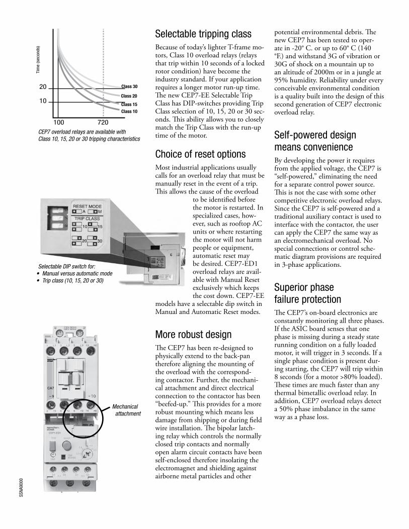
Selectable tripping classBecause of today’s lighter T-frame mo-tors, Class 10 overload relays (relays that trip within 10 seconds of a locked rotor condition) have become the industry standard. If your application requires a longer motor run-up time. The new CEP7-EE Selectable Trip Class has DIP-switches providing Trip Class selection of 10, 15, 20 or 30 sec-onds. This ability allows you to closely match the Trip Class with the run-up time of the motor.
Choice of reset optionsMost industrial applications usually calls for an overload relay that must be manually reset in the event of a trip. This allows the cause of the overload
to be identified before the motor is restarted. In specialized cases, how-ever, such as rooftop AC units or where restarting the motor will not harm people or equipment, automatic reset may be desired. CEP7-ED1 overload relays are avail-able with Manual Reset exclusively which keeps the cost down. CEP7-EE
models have a selectable dip switch in Manual and Automatic Reset modes.
More robust designThe CEP7 has been re-designed to physically extend to the back-pan therefore aligning the mounting of the overload with the correspond-ing contactor. Further, the mechani-cal attachment and direct electrical connection to the contactor has been “beefed-up.” This provides for a more robust mounting which means less damage from shipping or during field wire installation. The bipolar latch-ing relay which controls the normally closed trip contacts and normally open alarm circuit contacts have been self-enclosed therefore insolating the electromagnet and shielding against airborne metal particles and other
potential environmental debris. The new CEP7 has been tested to oper-ate in -20° C. or up to 60° C (140 °F.) and withstand 3G of vibration or 30G of shock on a mountain up to an altitude of 2000m or in a jungle at 95% humidity. Reliability under every conceivable environmental condition is a quality built into the design of this second generation of CEP7 electronic overload relay.
Self-powered design means convenienceBy developing the power it requires from the applied voltage, the CEP7 is “self-powered,” eliminating the need for a separate control power source. This is not the case with some other competitive electronic overload relays. Since the CEP7 is self-powered and a traditional auxiliary contact is used to interface with the contactor, the user can apply the CEP7 the same way as an electromechanical overload. No special connections or control sche-matic diagram provisions are required in 3-phase applications.
Superior phase failure protectionThe CEP7’s on-board electronics are constantly monitoring all three phases. If the ASIC board senses that one phase is missing during a steady state running condition on a fully loaded motor, it will trigger in 3 seconds. If a single phase condition is present dur-ing starting, the CEP7 will trip within 8 seconds (for a motor >80% loaded). These times are much faster than any thermal bimetallic overload relay. In addition, CEP7 overload relays detect a 50% phase imbalance in the same way as a phase loss.
CEP7 overload relays are available with Class 10, 15, 20 or 30 tripping characteristics
Additional Protection with Side Mount ModulesThe CEP7 offers a variety of field installable accessories for side mount on the left side. Side mount modules provide additional motor protection functionality traditionally found only on more expensive models. Modules include the following additional features.• Remote Reset provision for reset
after trip from a remote pilot device• Jam Protection/Remote Reset
provides adjustable Jam set points and trip delay plus remote reset
• Ground Fault Protection/Remote Reset combined with ground fault current transformers provide adjustable set points for ground fault trip protection of equipment plus remote reset
• Ground Fault/Jam Protection/Remote Reset combines all three features as described above
• PTC Thermistor Relay/Remote Reset manages thermistor sensor signals from the motor
• Network Communication Modules provide motor diagnostic information via Profibus or Ethernet communication- Two discreet Inputs and one
discreet Output- Differentiate between various
motor protection algorithms- Overload and underload warning- Jam protection- Proactively alert maintenance
Increased accuracy and improved motor protectionMicroelectronics provides flexible and accurate motor overload protection. Unlike traditional overload relays that simulate heat build-up in the motor by passing current through a heater element, CEP7 solid state overload relays measure motor current directly through integrated current transformers. The transformers, in turn, create a magnetic field that induces DC voltage onto the ASIC board. The electronics identify excessive current or loss of phase more accurately, and react to the condition with greater speed and reliability, than traditional overload relays. In addition, CEP7 solid state relays offer setting accuracies from 2.5 – 5% and repeat accuracy of 1%.
Dramatically lowered energy requirement saves money, reduces panel spaceBecause traditional overload relays work on the principle of “modeling” the heat generated in the motor (recreating the heat in the bimetal elements or heaters), a significant amount of energy is wasted. In traditional bimetallic overload relays, as many as six watts of heat are dissipated to perform the protective function. Because the CEP7 uses sampling techniques to actually measure the current flowing in the circuit, very little heat is dissipated in the device…as little as 150 milliwatts. This not only reduces the total amount of electrical energy consumed in an application, but it can also have a dramatic impact on the design and layout of control panels. The density of motor starters can be much greater because less heat is generated by each of the individual components. Higher density results in smaller control panels. In addition, special ventilation or air conditioning that might have been required to protect sensitive electronic equipment such as PLC’s can now be reduced or eliminated. CEP7 overload relays dramatically reduced energy requirement saves money and reduces panel space.
SSNA
9000
Discount Schedule A-1
Overload RelayDirectly Mounts to Contactor… ➋
Adjustment Range (A)
Adjustable Trip Class 10, 15, 20 & 30
Catalog Number Price
Automatic or Manual Reset for 3Ø Applications ➊
CA7-9…CA7-23
CAN7-12
0.1…0.5 CEP7-EEAB 88
0.2…1.0 CEP7-EEBB 88
1.0…5.0 CEP7-EECB 88
3.2… 16 CEP7-EEDB 88
5.4…27 CEP7-EEEB 88
CA7-30…CA7-43CAN7-30
1.0…5.0 CEP7-EECD 138
3.2…16 CEP7-EEDD 138
5.4…27 CEP7-EEED 138
9…45 CEP7-EEFD 138
CA7-60…CA7-85CAN7-72
5.4…27 CEP7-EEEE 158
9…45 CEP7-EEFE 158
18…90 CEP7-EEGE 164
Automatic or Manual Reset for 1Ø Applications ➊
CA7-9…CA7-23
CAN7-12
1.0…5.0 CEP7S-EEPB 88
3.2…16 CEP7S-EERB 88
5.2…27 CEP7S-EESB 88
CA7-30…CA7-43CAN7-30 9…45 CEP7S-EETD 138
CA7-60…CA7-85CAN7-72 18…90 CEP7S-EEUE 164
Solid State Overload RelaysCEP7 - Second Generation
Directly Mounted CEP7 Solid State Overload Relays, Manual Reset ➊➋➍
Overload RelayDirectly Mounts to Contactor… ➋
Adjustment Range (A)
Trip Class 10
Catalog Number Price
Manual Reset for 3Ø Applications ➊
CA7-9…CA7-23CAN7-12
0.1…0.5 CEP7-ED1AB 77
0.2…1.0 CEP7-ED1BB 77
1.0…5.0 CEP7-ED1CB 77
3.2… 16 CEP7-ED1DB 77
5.4…27 CEP7-ED1EB 77
CA7-30…CA7-43CAN7-30
5.4…27 CEP7-ED1ED 123
9…45 CEP7-ED1FD 123
Directly Mounted CEP7 Solid State Overload Relays, Automatic/Manual Reset ➊➋➌➍
➊ 3-phase CEP7 units are only designed for 3Ø applications. Single phase CEP7S units are only designed for single phase applications.
➋ This reference is not intended to be a guide for selecting contactors. Size overload relays using the full load current of the motor.
➌ The reset time of a CEP7 set in the automatic mode is approximately 180 seconds.➍ CEP7 overload relays do not work with Variable Frequency Drives, DC Applications or Softstarters
with braking options.
Most industrial applications usually call for an overload relay that must be manually reset in the event of a trip. This allows the cause of the over-load to be identified before the motor is restarted. An overload relay that resets automatically is gen-erally for specialized, or remote applications, such as rooftop AC units where restarting the motor will not harm people or equipment.
TIP!
SSNA
9000
Overload RelaySeparate Mount for use with… ➋
Adjustment Range (A)
Trip Class 10
Catalog Number Price
Manual Reset for 3Ø Applications ➊➍
Fig. 1
CA8-09…12CA7-9…CA7-23CAN7-12, CAN7-30
1.0…5.0 CEP7-ED1CP
773.2… 16 CEP7-ED1DP
5.4…27 CEP7-ED1EP
Overload RelaySeparate Mount for use with… ➋
Adjustment Range (A)
Adjustable Trip Class 10, 15, 20 & 30
Catalog Number Price
Automatic or Manual Reset for 3Ø Applications ➊➌➍
Fig. 1
CA8-09…12
CA7-9…CA7-23
CAN7-12, CAN7-30
1.0…5.0 CEP7-EECP
883.2… 16 CEP7-EEDP
5.4…27 CEP7-EEEP
Automatic or Manual Reset for 1Ø Applications ➊➌➍
Fig. 1
CA8-09…12
CA7-9…CA7-23
CAN7-12, CAN7-30
1.0…5.0 CEP7S-EEPP
883.2…16 CEP7S-EERP
5.2…27 CEP7S-EESP
Solid State Overload RelaysCEP7 - Second Generation
Pass-Thru CEP7 Solid State Overload Relays ➎
➊ 3-phase CEP7 units are only designed for 3Ø applications. Single phase CEP7S units are only designed for single phase applications.
➋ This reference is not intended to be a guide for selecting contactors. Size overload relays using the full load current of the motor.
➌ The reset time of a CEP7 set in the automatic mode is approximately 180 seconds.➍ CEP7 overload relays do not work with Variable Frequency Drives, DC Applications or Softstarters
with braking options.➎ Pass-Thru windows will accept one power wire up to #10 AWG wire (6mm2).
Description Fig. 1 - The Pass-Thru version of the CEP7 permits separate mounting of the overload relay. Fig. 2 - Motor load side cables simply pass-thru a window in the overload relay body. The internal current transformers monitor the current flow.
Benefits• Noneedforapanelmountadapteras
required with direct-connect versions•Eliminates3to6wireterminations• DesignedforusewithCA8orCA7
Contactors• Easilyreplacesoutdatedoverloadrelays
in existing starter assemblies• Providesstate-of-the-artaccuracyand
motor protection
Pass-thru window
Fig. 2
Fig. 1
SSNA
9000
Solid State Overload Relays & AccessoriesCEP7 - Second Generation
Overload RelayDirectly Mounts to
Contactor… ➋ CT RatioAdjustment Range (A)
Selectable Trip Class (10,15,20 & 30)
Catalog Number Price
Automatic or Manual Reset for 3Ø Applications ➊➌
CEP7-EEHF
CA6-95…110CAN6-110 No CT 60…120 CEP7-EEVF ➑ 285
CA6-95…-180CA6-95-EI…-180-EICAN6-110(EI) or 180(EI)
150:5 30…150 CEP7-EEHF 508
200:5 40...200 CEP7-EEJF 508
CA6-210-EI…-420-EICAN6-300-EI
200:5 40...200 CEP7-EEJG 888
300:5 60...300 CEP7-EEKG 888
500:5 100...500 CEP7-EELG 888
CA6-630-EI…-860-EI600:5 120...600 CEP7-EEMH 1397
800:5 160...800 CEP7-EENH 1397
Large Amp CEP7 Solid State Overload Relays, Automatic and Manual Reset ➊➋➌➍➐
➊ 3-phase CEP7 units are only designed for 3∅ applications.➋ This reference is not intended to be a guide for selecting contactors. Size overload
relays using the full load current of the motor.➌ The reset time of a CEP7 set in the automatic mode is approximately 180 seconds.➍ CEP7 Overload relays do not work with Variable Frequency Drives or any Sprecher +
Schuh Softstarter with braking options.➎ CA6-HB1 is not applicable with CEP7.➏ Terminal covers not necessary when using CA6-HB-_ insulated lugs.
➐ CEP7-EEHF…CEP7-EENH include current transformers used to monitor high amper-age. CEP7-EEVF directly monitors amperage. No current transformer is necessary.
➑ CEP7-EEVF is supplied with load side lugs internally mounted (see pg. B12) CEP7-EEVF not for use with CA6-95-EI or CA6-110-EI. Series B Range was 55…110 and Series C expanded to 60…120 starting Nov. 2009.
➒ Terminal Covers not necessary when using Main Terminal Sets (CA6-HB…) which are insulated.
Load Side Lugs & AccessoriesLug or Accessory Description For Use With... Catalog Number Price
CA6-HB
Main Terminal Set, ➎Dual Conductor, Touch Safe• Accommodation for dual connections to each pole• Accepts flat or round conductors• Touch safe to IP20 according to IEC 60529• Eliminates need for Terminal Shields
(price as complete set, containing 2 blocks, 6 lugs)
CEP7-EEHF CEP7-EEJF
CA6-HB2
See page A101
CEP7-EEJGCEP7-EEKGCEP7-EELG
CA6-HB3
CA6-L180 CA6-L420
Screw Type Lugs -• Accepts round conductors only• Copper construction
(set of 3 lugs)
CEP7-EEHF CEP7-EEJF
CA6-L180
CEP7-EEJGCEP7-EEKGCEP7-EELG
CA6-L420
CA6-L630
Screw Type Lugs -• Accommodation for dual connections to each pole• Copper construction accepts round conductors only
(set of 3 lugs)
CEP7-EEMHCEP7-EENH
CA6-L630
CA6-L860
Screw Type Lugs -• Accommodation for dual connections to each pole• Copper construction accepts round conductors only
(set of 3 lugs)
CEP7-EEMHCEP7-EENH
CA6-L860
Main Terminal Cover - ➒• CA6 touch protection• Line or load (price each)• IP20; IEC60529 & DIN 40 050 protection
CA6-95(-EI) to 180(-EI)CA6-210-EI to 420-EI CA6-630-EI to 860-EI
CA6-TC180 CA6-TC420 CA6-TC860
See page A103
SSNA
9000
Accessories – Field InstallableCEP7 - Second Generation Solid State Overload Relays
Accessories - CEP7 Side Mount Modules ➊➋
Accessory Description For use with… Catalog Number Price
CEP7-ERR
Remote Reset Module (Series B)• Dip switch adjustable reset mode & type - Automatic or Manual reset mode - 1- or 3-Phase relay type operation• Provision for reset after trip from remote pilot device
Side-mountto any
CEP7-EE_CEP7S-EE_
CEP7-ERR 100
CEP7-EJM
Jam Protection and Remote Reset Module ➌• Dip switch adjustable Jam Protection - Jam set points -150%, 200%, 300%, or 400% FLA - Trip delay- 0.5, 1, 2, or 4 sec.• Provision for reset after trip from remote pilot device
CEP7-EJM 110
CEP7-EPT
PTC Thermistor Relay and Remote Reset Module• PTC Protection and LED Status indication Type of Control Unit Mark A Number of Sensors 6 Maximum Cold Resistance of Sensor Chain 1500 Ω Trip Resistance 3400 Ω ± 150 Ω Reset Resistance 1600 Ω ± 50 Ω Short Circuit Trip Resistance 25 Ω ± 10 Ω Open Circuit Trip Resistance > 20,000 Ω Maximum Voltage at 1T1 / 1T2 (Rptc=4kΩ) < 7.5 Vdc Maximum Voltage at 1T1 / 1T2 (Rptc=open) < 30 Vdc PTC Response Time 500ms…800ms• Provision for reset after trip from remote pilot device
Side-mountto any
CEP7-EE_CEP7S-EE_
CEP7-EPT 125
PROFIBUS CEP7-EPRB
Network Communication Modules• Delivers direct access to motor performance and diagnostic
data on a field bus based network in addition to seamless control
• Includes integrated I/O 2 inputs
1 output• Operational and diagnostic data
Average motor current Percentage of thermal capacity usage Device status Trip and warning identification Trip history (last five trips)
➊ Side mount modules must have 24 - 240V, 47 - 63HZ or DC applied to terminals A1 and A2 for control power.➋ See page B16 for Technical Data, Wiring, and DIP Switch set up.➌ Dynamic inhibit: Protective function is enabled after the motor current goes above 150% and then falls below 125%.
SSNA
9000
CEP7 Ground Fault Sensor Selection ➌Ground fault current is sensed by passing all lines carrying current to and from a motor through the window of a special current transformer called a ground fault sensor. If all the current to the motor returns through the lines in the sensor window, no significant current will be induced in the sensor secondary. If, however, ground fault current returns via a path external to the sensor, such as via the conduit walls, a current will be induced in the sensor secondary. This current will be sensed and amplified by solid state circuits. If the ground fault current is larger than the selected ground fault trip level of the overload relay, the overload relay will trip.
Accessory Description For use with… Catalog Number Price
CEP7-EGF
Ground Fault Protection and Remote Reset Module ➋➏• Dip switch adjustable Ground Fault Protection > GF Current range set points - 20…100ma - 100…500mA - 0.2…1.0A - 1.0…5.0A > GF Trip level 20%-100%• LED status indication• Provision for reset after trip from remote pilot device
Side-mountto any
CEP7-EE_CEP7S-EE_
Must use withCEP7-CBCT_
Current Sensor
CEP7-EGF 110
CEP7-EGJ
Ground Fault/Jam Protection and Remote Reset Module ➋➏• Dip switch adjustable Ground Fault Protection same as CEP7-EGF shown above.• Jam trip when the motor current exceeds 400% FLA setting when enabled.• LED status indication• Provision for reset after trip from remote pilot device
CEP7-EGJ 145
Adjustment Cover for External Modules All modules withDIP Switches
CEP7-EMC 6.50
Accessories – Field InstallableCEP7 - Second Generation Solid State Overload Relays
Accessories - CEP7 Side Mount Modules ➊➌
➊ Side mount modules must have 24 - 240V, 47 - 63HZ or DC applied to terminals A1 and A2 for control power.
➋ ATTENTION: The CEP7 Overload relay is not a ground fault circuit interrupter for personnel protection as defined in Article 100 of the NEC.
➌ See page B16 for Application Details.➍ For a three phase system with one cable per phase.➎ For a three phase system with two cables per phase.➏ Dynamic inhibit: Protective function is enabled after the motor current goes above
150% and then falls below 125%.
Ground Fault Sensor Control Wiring
Motor
L2 L3L1
GroundFault
Sensor
CEP7Overload Relay
with Side Mount Module
S1 S2
CEP7 Ground Fault Sensor Installation
SSNA
9000
Accessories – Field InstallableCEP7 - Second Generation Solid State Overload Relays
Humidity Operating [%] 5…95, non-condensingDamp Heat per IEC 68-2-3 and IEC 68-2-30
Vibration (per IEC 68-2-6) [G] 3Shock (per IEC 68-2-27) [G] 30Maximum Altitude [m] 2000Pollution Environment Pollution Degree 3Degree of Protection IP20Type of Relay Ambient compensated, time delay, phase loss standardNature of Relay Solid-stateTrip Rating 120% FLATrip Class Type ED 10
Type EE 10, 15, 20, 30Reset Mode Type ED Manual
Type EE Manual or Automatic
Electromagnetic CompatibilityElectrostatic Discharge Immunity Test Level [kV] 8kV air discharge
6kV contact dischargePerformance Level 1 ➊➋
RF Immunity Test Level [V/m] 10 V/mPerformance Level 1 ➊➋
Electrical Fast Transient Burst Immunity Test Level [kV] 4 kVPerformance Level 1 ➊➋
Surge Immunity Test Level [V/m] 2 kV (L-E)1 kV (L-L)
Performance Level 1 ➊➋
GeneralStandards UL 508, CSA C22.2 No. 14, NEMA (CD2-1993 Part 4, EN 60947-4-1, EN 60947-5-1Approvals CSA, UL, ATEX (pending)
for Single Phase ApplicationsCEP7 Single Phase Overload Relay
MustbeconnectedasshowninFig.1or2only.
Fig. 1Recommended connections for CEP7S (i.e. 240V motors)
Fig. 2Optional connections
for CEP7S (i.e. ≤120V motors)
Fig. 3
➌ DO NOT USE
➊ Performance Criteria 1 requires the DUT to experience no degradation or loss of performance.
➋ Environment 2.
➌ If the CEP7S is connected as shown in Fig. 3 the overload will not trip! The CEP7S contains an electronic circuit board that is self powered. If connected as shown in Fig. 3, the CEP7S circuit board will not power up and the CEP7S would not trip.
➍ Connecting a CEP7S in this manner powers the elec-tronic circuit board. Connecting a 3-phase CEP7 in this manner to handle 1-phase will NOT work.
SSNA
9000
Technical InformationCEP7 - Second Generation Solid State Overload Relays
Technical Information
Trip Curve Legend Cold Trip Hot Trip
Trip Curves ➊
➊ Typical reset time for CEP7 Second Generation devices set to "automatic reset" mode is 120 seconds.
SSNA
9000
Technical InformationCEP7 - Second Generation Solid State Overload Relays
Overload Relay TypeSW2 3 Phase: 1 1 Phase: 0SW3 Not Used
CEP7-EJM Operational LED CEP7-EJM Dip Switch
Status LED: Steady Green- Module is powered up.
Adjustment Settings
Remote ResetSW1 Enable: 1 Disable: 0
Jam ProtectionSW2 Enable: 1 Disable: 0
Jam Trip LevelSW3 SW4
150% 0 0200% 0 1300% 1 0400% 1 0
Jam Trip DelaySW5 SW6
0.5 sec 1 11 sec 1 02 sec 0 14 sec 0 0 ➊
CEP7-EPT Wiring Diagrams CEP7-EPT Operational LED CEP7-EPT Dip Switch
2R
1R
2TI
1TI
2A
1A A1
A2
R1
R2
IT2IT1
• Apply 24 - 240V, 47 - 63HZ or DC to terminals A1 and A2 for control power.• Connect remote reset pilot device to Terminals R1 and R2• Connect Terminal IT1 and IT2 to PTC Chain
Status LED: Steady Green - Module is powered up Flashing LED - The number of flashes followed by
a pause identifies the specific trip code as follows:
Steady Red - Hardware fault. Internal hardware fault detected and CEP7 trip attempted.
Adjustment Settings
SW1 Manual: I
SW2 Enable: I
Overload Relay and PTC Reset Mode
PTC ProtectionDisable: 0
Automatic: 0
SW3 3 Phase: IOverload Relay Type
1 Phase: 0
➋
➊ Dynamic inhibit: Protective function is enabled after the motor current goes above 150% and then falls below 125%. ➋ The delay between the occurrence of a PTC out-of-range fault and a trip of the CEP7 varies, but is generally described by one of the following: a) 500 ms ± 250 ms, typi-
cal; or b) < 6 seconds, for a PTC out-of-range fault present at power-up of the side mount module. Under no conditions should a PTC trip take longer than 6 seconds.
Electrical DataPower Supply Ratings:Rated Supply Voltage Us 24V DCRated Operating Range Ue 20.4 - 26.4Rated Supply Current Ie 0.1 AMaximum Surge Current at Power-Up 2.5 AMaximum Power Consumption 2.5…2.7 WOutput Relay Ratings:
TerminalsOUT A: 13/14
Type of Contacts Form A SPST - NORated Thermal Current Ithe 5 ARated Insulation Voltage Ui 300V ACRated Operating Voltage Ue 240V ACRated Operating Current Ie 3 A (at 120V AC), 1.5 A (at 240V AC)
0.25 A (at 110V DC), 0.1 A (at 220V DC)Minimum Operating Current 10 mA at 5V DCRating Designation B300Utilization Category AC-15Resistive Load Rating(p.f.=1.0)
5 A, 250V DC5 A, 30V DC
Inductive Load Rating(p.f.=0.4), (L/R=7 ms)
2 A, 250V AC2 A, 30V DC
Short Circuit Current Rating 1,000 ARecommended Control Circuit Fuse KTK-R-6
(6 A, 600V)Input Ratings:
TerminalsIN1:IN2:SSV (Sensor Supply Voltage)
123
Supply Voltage (Provided my module) 20.4 - 26.4V DCType of Inputs Current Sinking
Jam Protection:Trip Level 150…600% FLATrip Delay 0.1…25.0 sec.Inhibit 0…250 sec.
• Apply 24 - 240V, 47 - 63HZ or DC to terminals A1 and A2 for control power.• Connect remote reset pilot device to Terminals R1 and R2• Connect current sensor to Terminal S1 and S2
Status LED: Steady Green - Module is powered up.Flashing LED - The number of flashes followed by
a pause identifies the specific trip code as follows:
and CEP7 not yet capable of tripping. Steady Red - Hardware fault. Internal hardware fault
detected and CEP7 trip attempted.
SW8 Enable: I Jam Protection
Disable: 0
Adjustment Settings
SW1 Manual: I
SW 2 SW30 00 II 0I I
SW 4 SW 6SW 50 0
00
0 I00IIII
0
0
II I
I
III00
0
20...100mA100...500mA0.2...1.0A1.0...5.0A
Overload Relay Reset Mode
Ground Fault Current Range
Ground Fault Trip Level
Automatic: 0
SW7 3 Phase: I Overload Relay Type
1Phase: 0
Disable/Off20% Max GF Current35% Max GF Current50% Max GF Current65% Max GF Current80% Max GF Current90% Max GF Current100% Max GF Current
➊ Dynamic inhibit: Protective function is enabled after the motor current goes above 150% and then falls below 125%.
SSNA
9000
Technical Information/DimensionsCEP7 - Second Generation Solid State Overload Relays
CEP7-CBCT Installation
6X
6X
ØX
6X
Ø X
Single Cable per Phase
A
B C
CEP7-CBCT DimensionsCEP7-CBCT1
11.8(.47)
3.2(.13)
45.3(1.78)
23.1(.91)
Ø 19.1(Ø .75)
Ø 44.5(Ø 1.75)
Ø D
63.5(2.50)
50.8(2.00)
3.2(.12)
4(.16)
5.3(.21)
12.7(.50)
E
F B
A
C
96(3.78)
CAT
CEP7-CBCT2
A
89.6(3.53)
B
48.3(1.90)
C
Dimensions
39.6(1.56)
ø D
54.6(2.15)
E
69.9(2.75)
122.4(4.82)CEP7-CBCT3 115.9
(4.56)59.7
(2.35)63.5
(2.50)54.1
(2.13)96
(3.78)
F
44.5(1.75)
56.2(2.21)
74.4(2.93)
123.2(4.85)
96.7(3.81)
CEP7-CBCT2CEP7-CBCT3
CEP7-CBCT4
CEP7-CBCT1
11.8(.47)
146.8(5.78)
143.5(5.65)
5.5(.22)
74.9(2.95) 3.2
(.13)
82.6(3.25)
CEP7-CBCT4
11.8(.47)
3.2(.13)
45.3(1.78)
23.1(.91)
Ø 19.1(Ø .75)
Ø 44.5(Ø 1.75)
Ø D
63.5(2.50)
50.8(2.00)
3.2(.12)
4(.16)
5.3(.21)
12.7(.50)
E
F B
A
C
96(3.78)
CAT
CEP7-CBCT2
A
89.6(3.53)
B
48.3(1.90)
C
Dimensions
39.6(1.56)
ø D
54.6(2.15)
E
69.9(2.75)
122.4(4.82)CEP7-CBCT3 115.9
(4.56)59.7
(2.35)63.5
(2.50)54.1
(2.13)96
(3.78)
F
44.5(1.75)
56.2(2.21)
74.4(2.93)
123.2(4.85)
96.7(3.81)
CEP7-CBCT2CEP7-CBCT3
CEP7-CBCT4
CEP7-CBCT1
11.8(.47)
146.8(5.78)
143.5(5.65)
5.5(.22)
74.9(2.95) 3.2
(.13)
82.6(3.25)
CEP7-CBCT2 & 311.8(.47)
3.2(.13)
45.3(1.78)
23.1(.91)
Ø 19.1(Ø .75)
Ø 44.5(Ø 1.75)
Ø D
63.5(2.50)
50.8(2.00)
3.2(.12)
4(.16)
5.3(.21)
12.7(.50)
E
F B
A
C
96(3.78)
CAT
CEP7-CBCT2
A
89.6(3.53)
B
48.3(1.90)
C
Dimensions
39.6(1.56)
ø D
54.6(2.15)
E
69.9(2.75)
122.4(4.82)CEP7-CBCT3 115.9
(4.56)59.7
(2.35)63.5
(2.50)54.1
(2.13)96
(3.78)
F
44.5(1.75)
56.2(2.21)
74.4(2.93)
123.2(4.85)
96.7(3.81)
CEP7-CBCT2CEP7-CBCT3
CEP7-CBCT4
CEP7-CBCT1
11.8(.47)
146.8(5.78)
143.5(5.65)
5.5(.22)
74.9(2.95) 3.2
(.13)
82.6(3.25)
Catalog Number A B C øD E F
CEP7-CBCT296
(3.78)89
(3.53)48.3
(1.90)39.6
(1.56)54.6
(2.15)69.9
(2.75)
CEP7-CBCT3122.4(4.82)
115.9(4.56)
59.7(2.35)
63.5(2.50)
54.1(2.13)
96(3.78)
CEP7-CBCT Ground Fault Trip Data ATTENTION: The CEP7 Overload relay is not a ground fault circuit interrupter for personnel protection as defined in Article 100 of the NEC.
Ground fault trip delay: The delay between the occurrence of a ground fault and a trip of the CEP7 varies, but is generally described by one of the following: 50 ms ± 20 ms, typical < 6 seconds, for a ground fault present at power-up of the side mount module < 30 seconds, if the protection inhibit has not been cleared.
Under no conditions should a ground fault trip take longer than 31 seconds.Dynamic inhibit: Protective function is enabled after the motor current goes above 150% and then falls below 125%.
Dimensions are in millimeters (inches). Dimensions not intended for manufacturing purposes.
SSNA
9000
CEP7 Mounted to CA7 Contactor
Overload Mounted to Contactor
AWidth
BHeight
CDepth D E1 E2 F H1 H2
CEP7-ED1ED..FDCEP7-ED…BCEP7-EE…B
CEP7S-EE…B
CA7-9…23 45(1-25/32)
146.6(5-25/32)
85.2(3-23/64)
4.5(3/16)
13.9(35/64)
24.5(31/32)
86.5(3-13/32)
60(2-23/64)
35(1-3/8)
CEP7-EE…DCEP7S-EE…D CA7-30…37 45
(1-25/32)146.6
(5-25/32)101.2
(3-63/64)4.5
(3/16)13.9
(35/64)24.5
(31/32)104
(4-3/32)60
(2-23/64)35
(1-3/8)
CEP7-EE…DCEP7S-EE…D CA7-43 54
(2-1/8)146.6
(5-25/32)101.2
(3-63/64)4.5
(3/16)18.9(3/4)
24.5(31/32)
107(4-3/32)
60(2-23/64)
45(1-25/32)
CEP7-EE…ECEP7S-EE…E CA7-60…85 72
(2-53/64)192.3
(7-37/64)120.4(4-3/4)
5.4(7/32)
23.8(15/16)
29(1-9/64)
125.5(4-15/16)
100(3-15/16)
55(2-11/64)
DimensionsCEP7 - Second Generation Solid State Overload Relays
Dimensions are in millimeters (inches). Dimensions not intended for manufacturing purposes.
SSNA
9000
DimensionsCEP7 - Second Generation Solid State Overload Relays
CEP7 Pass-thru Overload
44.8
35
13.9
(.18 ø)ø 4.5
3.589
(2.31)58.6
(1.97)50
(1.44)36.7
(1.76)
(1.38)
(.55)
(.14)(3.50)
CEP7-ERID Remote Indicator
R1
R2
R1
R2
A1
A2
A1
A2CEP7-ERID is to be used with Series B or later:CEP7-EJMCEP7-ERRCEP7-EPTCEP7-EGFCEP7-EGJ
0.56 - 0.79 N.m(5 - 7 lb-in)
7mm(.28 in)
0.6mm X 3.5mm Blade(.02 in X .14 in Blade)
Function edoC hsalFsutatS ro tluaF.D.E.LModule Power Green (Flash)
Overload Trip Red (Solid)
Overload Warning (> 110%) Yellow (Flash)
Phase Loss Trip Red (Solid)
Module Power + Motor Current Green (Solid)Hardware Fault Red (Solid)