Department of Physics, Bar-Ilan University, Ramat-Gan, Israel
Received October 7, 1985; accepted November 6, 1985
We present the first reported optical second-harmonic microscope images of a biological sample-rattail tendon-and discuss, also for the first time, the need to distinguish between coherent and incoherent second-harmonicimaging. Our data show that the currently unexplained macroscopic polar order of this classic representative ofconnective tissue is due both to a coherent network containing a large number of fine, polar, filamentlike structuresthat permeate the entire tendon volume and to a small number of intensely polar surface patches.
The recently developed technique of second-harmonicmicroscopy1 is unique in that it is capable of providingdirect information on the scale and form of molecularordering in microscopic structures. We discuss, forthe first time, coherent versus incoherent imagingtechniques, apply this new method to a previouslyintractable problem in biology, and present the firstreported second-harmonic microscope images of bio-logical tissue.
Some two decades ago Fukada and Yasuda2 andLang3 obtained indications that tendon has a macro-scopic polar structure but could not identify thesource of this structure. These pioneering studiesinvolved piezoelectric 2 and pyroelectric 3 measure-ments on dried tendon and subsequently gave rise tomany similar investigations in a wide variety of driedbiological systems.4 Attempts to confirm these re-sults in the native, wet tissue, however, proved fruit-less.5 Since the polar piezoelectric and pyroelectriccoefficients of the dried samples were very small, beingsome 2 orders of magnitude less than is usual for polarcrystals,6 the suggestion arose7 that perhaps dryingreduced the system symmetry and thereby gave rise tovarious small effects unrelated to the structure andfunction of the native, wet tissue. The transducer andother functions that had been proposed for the polari-ty were, of course, also called into question.
Tendon consists principally of polar collagen fibrilsarranged with their long axes parallel. In an exhaus-tive study of rattail tendon (RTT) by Parry andCraig,8 it was found that both locally and globally thenumbers of up- and down-pointing fibrils were equalto within the few-percent uncertainty of the countingstatistics, eliminating the collagen fibril as a signifi-cant candidate for the source of polarity. According-ly, for many years the problem of tendon polarityremained unresolved, in part because of the inherentlimitations of the electrical techniques and in partbecause of the absence of any structural clues.
Recently, using optical second-harmonic (SH) gen-eration,9 we were able to confirm the existence of amacroscopic polar order in native, wet RTT continu-ously maintained in physiological phosphate buffer.These results not only eliminated the uncertainties
present in dried tissue but resolved many other prob-lems as well. However, the SH coefficients werefound to be small (an order of magnitude less than d1lof quartz), so that still unresolved was the question ofwhat possible biological significance these small phys-ical effects could have.
Using scanning SH microscopy,1 we have now dis-covered that the polarity of RTT is due to a coherentnetwork composed of a large number of fine, filament-like structures as well as a small number of intensepolar patches that appear to be on or near the tendonsurface. We estimate that such polar material occu-pies only a few percent of the tendon volume; this,then, explains the apparent smallness of the piezoelec-tric, pyroelectric, and SH coefficients, which are onlyaverage values. The corollary of this is that the fila-ments and patches are strongly polar and are thusendowed with the unique physical and chemical prop-erties of strongly polar systems.6
The scanning SH microscope can be operated ineither a coherent or an incoherent imaging mode, apossibility that was not discussed previously. If theobject is orientationally ordered over dimensions largecompared with the wavelength of light, then a for-ward-directed, coherent SH beam is produced whoseangular divergence is determined either by the objectsize or by the divergence and the spot size of thescanning laser beam. If the object is not orientation-ally ordered, then it produces an incoherent SH beamwhose angular divergence is determined by the charac-teristic distance over which some degree of orienta-tional order is maintained. The SH intensity from anobject disordered on the scale of small molecules suchas water is so weak that it will not normally contributeto the image. Of course, the orientational order re-quired is such that no center of inversion may be pres-ent. Generally in biological systems one will be deal-ing with parallel arrays of molecules and, thus, withpolar units. This can be verified directly by varyingthe directions of polarization of the laser and SH.9
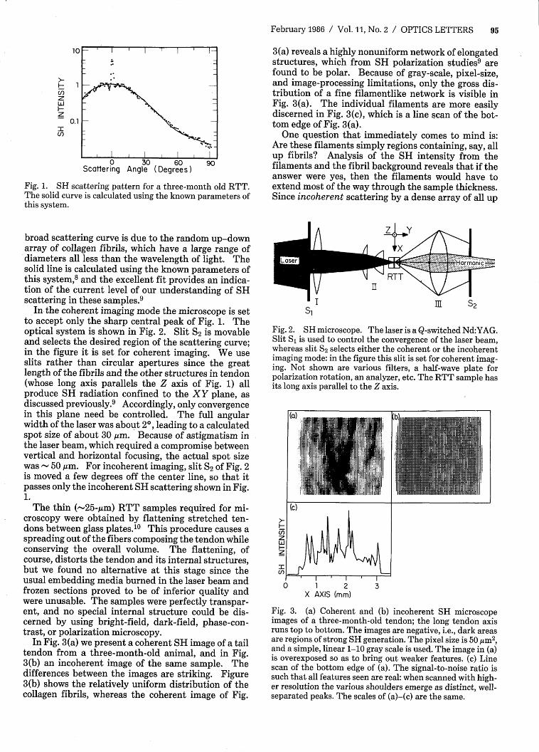
A good example of these principles is provided byRTT, as is shown by the data of Fig. 1. The sharp,coherent, central peak is due to a component withlong-range orientational order, and the incoherent,
Fig. 1. SH scattering pattern for a three-month old RTT.The solid curve is calculated using the known parameters ofthis system.
broad scattering curve is due to the random up-downarray of collagen fibrils, which have a large range ofdiameters all less than the wavelength of light. Thesolid line is calculated using the known parameters ofthis system,8 and the excellent fit provides an indica-tion of the current level of our understanding of SHscattering in these samples.9
In the coherent imaging mode the microscope is setto accept only the sharp central peak of Fig. 1. Theoptical system is shown in Fig. 2. Slit S2 is movableand selects the desired region of the scattering curve;in the figure it is set for coherent imaging. We useslits rather than circular apertures since the greatlength of the fibrils and the other structures in tendon(whose long axis parallels the Z axis of Fig. 1) allproduce SH radiation confined to the XY plane, asdiscussed previously. 9 Accordingly, only convergencein this plane need be controlled. The full angularwidth of the laser was about 20, leading to a calculatedspot size of about 30 gim. Because of astigmatism inthe laser beam, which required a compromise betweenvertical and horizontal focusing, the actual spot sizewas - 50 gim. For incoherent imaging, slit S2 of Fig. 2is moved a few degrees off the center line, so that itpasses only the incoherent SH scattering shown in Fig.1.
The thin (-25-,gm) RTT samples required for mi-croscopy were obtained by flattening stretched ten-dons between glass plates.10 This procedure causes aspreading out of the fibers composing the tendon whileconserving the overall volume. The flattening, ofcourse, distorts the tendon and its internal structures,but we found no alternative at this stage since theusual embedding media burned in the laser beam andfrozen sections proved to be of inferior quality andwere unusable. The samples were perfectly transpar-ent, and no special internal structure could be dis-cerned by using bright-field, dark-field, phase-con-trast, or polarization microscopy.
In Fig. 3(a) we present a coherent SH image of a tailtendon from a three-month-old animal, and in Fig.3(b) an incoherent image of the same sample. Thedifferences between the images are striking. Figure3(b) shows the relatively uniform distribution of thecollagen fibrils, whereas the coherent image of Fig.
3(a) reveals a highly nonuniform network of elongatedstructures, which from SH polarization studies9 arefound to be polar. Because of gray-scale, pixel-size,and image-processing limitations, only the gross dis-tribution of a fine filamentlike network is visible inFig. 3(a). The individual filaments are more easilydiscerned in Fig. 3(c), which is a line scan of the bot-tom edge of Fig. 3(a).
One question that immediately comes to mind is:Are these filaments simply regions containing, say, allup fibrils? Analysis of the SH intensity from thefilaments and the fibril background reveals that if theanswer were yes, then the filaments would have toextend most of the way through the sample thickness.Since incoherent scattering by a dense array of all up
,I UI m S2S.IH[ S
Fig. 2. SH microscope. The laser is a Q-switched Nd:YAG.Slit SI is used to control the convergence of the laser beam,whereas slit S2 selects either the coherent or the incoherentimaging mode: in the figure this slit is set for coherent imag-ing. Not shown are various filters, a half-wave plate forpolarization rotation, an analyzer, etc. The RTT sample hasits long axis parallel to the Z axis.
(a)
(c)
LU
U)
020 1 2 :3
X AXIS (mm)
=1-
Fig. 3. (a) Coherent and (b) incoherent SH microscopeimages of a three-month-old tendon; the long tendon axisruns top to bottom. The images are negative, i.e., dark areasare regions of strong SH generation. The pixel size is 50 /m 2 ,and a simple, linear 1-10 gray scale is used. The image in (a)is overexposed so as to bring out weaker features. (c) Linescan of the bottom edge of (a). The signal-to-noise ratio issuch that all features seen are real: when scanned with high-er resolution the various shoulders emerge as distinct, well-separated peaks. The scales of (a)-(c) are the same.
Fig. 4. Coherent images of different (a)-(c) one-month-,(d)-(f) three-month-, and (g) six-month-old tendons. In allimages the proximal end of the tendon is uppermost, exceptfor (e) where the orientation was not documented and isuncertain. Microscope and image processing parameters forall samples are the same as for Fig. 3(a). The scale for allimages is shown in (d).
fibrils is much less than from a random up-down ar-ray, the incoherent image in Fig. 3(b) would then haveto display gaps corresponding to filament locations.This is observed neither here nor in specific tests em-ploying coherent-incoherent line scans across regionscontaining exceptionally intense filaments. Thus ourdata eliminate the possibility that the filaments aresimply regions of all up fibrils. This is in accord withelectron microscope studies 8 in which no such regionswere found.
Another important question raised by Fig. 3 is:How thick are the polar filaments? The SH intensityproduced by frequency summation of two beams thatmake angles of ±O with the sample normal (the Y axis)is proportional to [sin2 (Akt/2)]/(Ak) 2 , where t is theeffective thickness of a polar filament and Ak =(4r/X1) (n2 cos 0- nj), with X the wavelength and n therefractive index, while the subscripts 1 and 2 refer tothe laser and the harmonic, respectively. By studyingcrossed-beam SH microscope images that are similarto those in Fig. 3, and also performing detailed quanti-tative analyses of the SH intensity as a function of 0,we concluded1 that most of the filaments were muchthinner than the SH coherence length 1c _ 10 gimestimated previously for RTT. 9 If we assume a thick-ness of a few micrometers for the polar filaments andpatches, and estimate the area these structures coveron our SH images, we conclude that generally the polarmaterial occupies only a few percent of the tendon
volume. This undoubtedly explains the smallness ofthe piezoelectric, pyroelectric, and SH coefficients,which are averages over the whole tendon.
We also studied small-angle SH scattering from se-lected groups of filaments. The measurements weremade by first using the SH microscope to select agroup of filaments and then sliding out of the beampath condensor II and collecting lens III, leaving onlylens I, which formed a weakly focused spot that illumi-nated the chosen group. The SH scattering patternswere measured by scanning slit S2 over a +1.5' range(this included essentially the whole pattern) using aninstrumental resolution of about 2 mrad. From anal-ysis of such patterns for a large number of differentfilament groups we were able to determine that thefilaments in a given tendon all are of the same direc-tionality (e.g., up) and that they permeate the tendoncross section in an apparently random fashion.
In Fig. 4 we display coherent SH microscope imagesfrom tendons ranging in age between one and sixmonths. There are no obvious systematic differencesvisible as a function of age. What is striking aboutthese images are the strong polar patches. Because ofthe flattening procedure, only regions on the tendonsurface can end up at the edges of the image. Theconverse is not, however, true, since a surface patchcould, depending on its initial azimuthal location, eas-ily end up at an image center. We note that in five ofthe seven tendons studied the polar patches are at ornear the image edges, implying, therefore, that theyare on or near the tendon surface.
We believe that these first results demonstrate theenormous potential of SH microscopy for the study ofbiological samples.
References
1. C. J. R. Sheppard and R. Kompfner, Appl. Opt. 17, 2879(1978); J. N. Garraway and C. J. R. Sheppard, Opt.Quantum Electron. 10, 435 (1978); C. J. R. Sheppard,Proc. Soc. Photo-Opt. Instrum. Eng. 368, 88 (1983).
2. E. Fukada and I. Yasuda, Jpn. J. Appl. Phys. 3, 117(1964).
3. S. B. Lang, Nature 212, 704 (1966).4. H. Athenstaedt, Nature 228, 830 (1970); Ann. N.Y.
Acad. Sci. 238, 68 (1974).5. J. C. Anderson and C. Eriksson, Nature 218, 166 (1968).6. J. F. Nye, Physical Properties of Crystals (Oxford U.
Press, London, 1964).7. W. Traub and K. A. 'Piez, Adv. Prot. Chem. 25, 243
(1971).8. D. A. D. Parry and A. S. Craig, Biopolymers 16, 1015
(1977); 17,843 (1978).9. S. Roth and I. Freund, Opt. Commun. 33, 292 (1980);
Biopolymers 20, 1271 (1981).10. S. Cusack and A. Miller, J. Mol. Biol. 135, 292 (1980).