36
SECTION 12 INS Page 149 INS

SECTION 12
INS
Page 149
INS

SECTION 12 12-1
INS INS INTRODUCTION
Page 150
12 – 1 - INERTIAL NAVIGATION SYSTEM INTRODUCTION
INS OPERATING PRINCIPLE
The INS is an autonomous navigation system that requires no external communication (VOR beacons, GPS satellites...) to operate. Based on a start position (the exact latitude / longitude and altitude of the starting point needs to be known) and using a very complex set of accelerometers and gyroscopes, it keeps track of the aircraft movement in space and calculates in a continuous manner the current position, route, speed, attitude and altitude.
SAGEM ULISS 52 UNI
The Sagem ULISS 52 UNI (Unitée de Navigation Intertielle – INS) is the heart of the M-2000C navigation system. This INS is composed of a computer that commands the INS platform and allows communication with panels or instruments. It also stores essential information used by the platform as well as navigation information used by the aircraft like the flight plan. The INS provide the aircraft with its position in the word as well as speed, heading, attitude and altitude. It can also provide course to a geographical point and various information to help the pilot perform navigation or weapon delivery.
The INS computer can store the following information:
• 20 BUTs that are navigation waypoints or ground attack targets. They can store the following information:
• Latitude and Longitude (L/G).
• Altitude (ALT).
• Runway true heading (CP – Cap Piste).
• Runway approach glideslope (PD – Pente Désirée).
• Desired arrival time (TD – Temps Désiré).
• Desired arrival track (RD – Route Désirée). Each BUT can also store a BAD (BUT Aditionnel) which is an offset waypoint or offset ground attack target. They can store the following information:
• Latitude and Longitude offset (ΔL/ΔG).
• Altitude offset (ΔALT).
• 3 Marques (MRQ) that are mark-points. They store the following information:
• Latitude and Longitude.
• Creation time.
• The magnetic declination (DEC)
The INS provide the following information:
• Aircraft geographical position (Latitude and Longitude).
• Horizontal components (Vx, Vy) of the inertial speed.
• Ground Speed.
SECTION 12 12-1
INS INS INTRODUCTION
Page 151
• Ground Track.
• Direction and Strength of the Wind.
• True Heading.
• Magnetic Heading.
• Acceleration components (Ax, Ay, Az).
• Bearing and distance to a waypoint.
• Track error.
• Magnetic lateral deviation from desired track.
• Track error from desired track.
• Approach glideslope.
• Remaining time to reach waypoint.
• Time difference between remaining time and desired arrival time in order to maintain a constant speed.
• The aircraft load factor.
Interface with INS Is done though two dedicated panels in the cockpit:
• The Poste de Commande Navigation PCN (Navigation Control Panel)
• The Poste Sélecteur de Modes PSM (Mode Selector Panel)
The INS computer provides information to the following instruments:
• VTH
• Radar
• VTB
• IS
• IDN
• PCN

SECTION 12 12-1
INS INS INTRODUCTION
Page 152
PLATFORM DRIFT
The INS is not a perfect tool, and suffers from integration drift - accumulated small errors in its velocity and orientation measurements. It will result in a difference between the real position of the aircraft and were the INS thinks the aircraft is, this error in position is growing with time. This drift can be measured by drift rate commonly using the nautical mile per hour (nm/h) unit. Due to the earth being round the drift rate is not linear or exponential in time but rather follows the Schuler period.
Mirage 2000C INS mean drift rate after a normal alignment
In the graphic above we can see that the rift rate will be at its at its highest at 42 minutes and be lowest at 84 minutes.
The experience drift rate will rarely look like the above graph as any change in attitude will influence the drift rate. The more changes, the more chaotic the drift will become. It is even common that the accumulated drift decreases at some point during long flight
The ULISS 52 UNI is a class 1 INS, meaning that it can achieve less that 1nm/h of drift rate on average. The real drift rate of this particular system is closer to 0,7nm/h but keep in mind that the chaotic nature of the system allows for large differences between flights. Even aircraft flying the same mission can have very different drift patterns.
The accumulated drift can be corrected by performing an INS position fix (see INS
POSITION UPDATE).
0
0,5
1
1,5
2
2,5
0,0 0,5 1,0 1,5 2,0 2,5 3,0 3,5
Dri
ft (
nm
)
Time (hour)
ALN drift rate

SECTION 12 12-2
INS PSM
Page 153
12 – 2 - MODE SELECTOR PANEL (PSM)
The Mode Selector Panel (PSM – Post sélecteur de modes) is the control panel for both the PCN and the INS and is responsible for controlling the INS operation.
1. MODE SELECTOR KNOB (Sélecteur de mode): Sets the INS operating mode:
• AR (Arrêt): Turns Off both the INS and the PCN
• VEI (Veille): The gyros remain off but the system is powered and thermal regulation is on. The PCN is available for data entry and visualization.
• CAL (Calibration): Reserved for maintenance. NOT FUNCTIONAL
• TST (Test): Reserved for maintenance. NOT FUNCTIONAL
• • ALN (Alignement normal): Normal alignment. (See INS ALIGNMENT for more
information)
• ALCM (Alignement sur cap mémorisé): Memorized heading alignment. (See INS
ALIGNMENT for more information).
• NAV (Navigation). Navigation mode.
• SEC (Secours): Emergency mode, the INS provide only gyroscopic information (attitude and heading).
2. DATA CARTRIDGE SLOT (Trappe du module d’insertion de paramètres): Used by the ground crew or the pilot to insert data into the INS using a data cartridge (MIP). NOT FUNCTIONAL
3. OPERATIONAL MODE SELECTOR KNOB (Sélecteur de mise en œuvre): Sets the PCN operating mode :
• N (Normal): Normal operating mode, for data entry and visualization.
• STS (Status): Used to display alignment status in ALN and ALCM modes and to start maintenance tests in TST mode.
• DCI (Données Codées Inertielles): Inertial Codes Input, used to visualize or enter certain parameters into the INS memory. Maintenance only. NOT FUNCTIONAL
• CRV (Compte-Rendu de vol): Flight report, used to generate a flight report for INS performance tracking. Maintenance only. NOT FUNCTIONAL
• MAIN (Maintenance): Used for maintenance only. NOT FUNCTIONAL
1 2 3

SECTION 12 12-3
INS PCN
Page 154
12 – 3 - NAVIGATION CONTROL PANEL (PCN)
The PCN (Poste de Commande Navigation) is responsible for the interface between the pilot and the INS. It is the main tool used for navigation, creating waypoints and displaying different flight parameters, including those for waypoints current aircraft position.
The main functions of the PCN are as follows:
• Visualization of the navigation data in the memory of the INS.
• Data input into the memory of the INS.
• Visualization of the INS alignment status.
• Selection of PREP and DEST BUT, BAD and MRQ waypoints.
• Creation, validation and rejection of MRQ mark-points.
• Creation, validation and rejection of INS position fixes.
Below you will find description of all the displays and buttons:
1. UPPER LEFT VISUALIZATION WINDOW: 6 digits separated by 5 points with symbols N, S, + and –. Displays INS data.
2. UPPER RIGHT VISUALIZATION WINDOW: 7 digits separated by 6 points with symbols E, W, + and –. Displays INS data.
3. LOWER VISUALIZATION WINDOWS: Displays 2 numbers just above the PREP and DEST buttons, they represents the selected BUT in PREP and DEST.
1 2
3 4
5
6
7
8
9
SECTION 12 12-3
INS PCN
Page 155
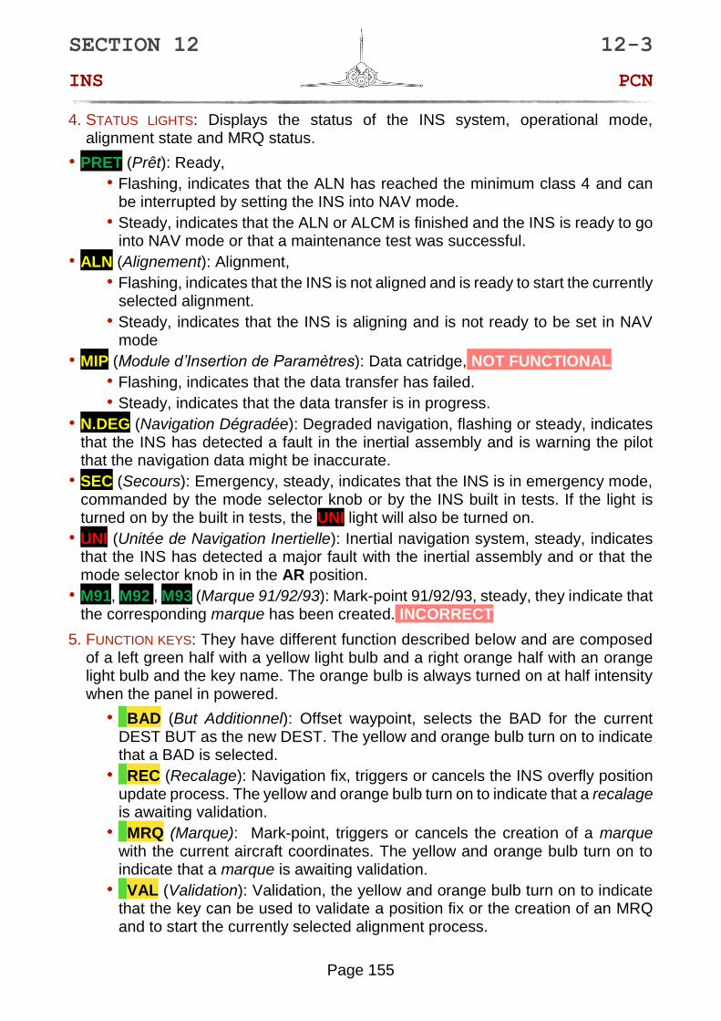
4. STATUS LIGHTS: Displays the status of the INS system, operational mode, alignment state and MRQ status.
• PRET (Prêt): Ready,
• Flashing, indicates that the ALN has reached the minimum class 4 and can be interrupted by setting the INS into NAV mode.
• Steady, indicates that the ALN or ALCM is finished and the INS is ready to go into NAV mode or that a maintenance test was successful.
• ALN (Alignement): Alignment,
• Flashing, indicates that the INS is not aligned and is ready to start the currently selected alignment.
• Steady, indicates that the INS is aligning and is not ready to be set in NAV mode
• MIP (Module d’Insertion de Paramètres): Data catridge, NOT FUNCTIONAL
• Flashing, indicates that the data transfer has failed.
• Steady, indicates that the data transfer is in progress.
• N.DEG (Navigation Dégradée): Degraded navigation, flashing or steady, indicates that the INS has detected a fault in the inertial assembly and is warning the pilot that the navigation data might be inaccurate.
• SEC (Secours): Emergency, steady, indicates that the INS is in emergency mode, commanded by the mode selector knob or by the INS built in tests. If the light is turned on by the built in tests, the UNI light will also be turned on.
• UNI (Unitée de Navigation Inertielle): Inertial navigation system, steady, indicates that the INS has detected a major fault with the inertial assembly and or that the mode selector knob in in the AR position.
• M91, M92 , M93 (Marque 91/92/93): Mark-point 91/92/93, steady, they indicate that the corresponding marque has been created. INCORRECT
5. FUNCTION KEYS: They have different function described below and are composed of a left green half with a yellow light bulb and a right orange half with an orange light bulb and the key name. The orange bulb is always turned on at half intensity when the panel in powered.
• BAD (But Additionnel): Offset waypoint, selects the BAD for the current DEST BUT as the new DEST. The yellow and orange bulb turn on to indicate that a BAD is selected.
• REC (Recalage): Navigation fix, triggers or cancels the INS overfly position update process. The yellow and orange bulb turn on to indicate that a recalage is awaiting validation.
• MRQ (Marque): Mark-point, triggers or cancels the creation of a marque with the current aircraft coordinates. The yellow and orange bulb turn on to indicate that a marque is awaiting validation.
• VAL (Validation): Validation, the yellow and orange bulb turn on to indicate that the key can be used to validate a position fix or the creation of an MRQ and to start the currently selected alignment process.

SECTION 12 12-3
INS PCN
Page 156
The specific use of the buttons are described in the BAD, MRQ, ALIGNMENT and POSITION FIX chapters.
6. BUT SELECTION KEYS: Used to select BUTs and have a yellow light bulb that turns on when the button is pressed and the PCN is waiting for the pilot to input the desired BUT number.
• PREP (Préparation): Preparation, selects the preparation BUT for data display or entry on the PCN.
• DEST (Destination): Navigation, selects navigation BUT that is going to provide information for the VTH and IDN.
7. NUMERIC KEYPAD: Used to enter data into the INS. Consists of:
• NUMERIC KEYS: from 0 to 9. Including keys to designate North, South, East, West, + and -.
• EFF (Effacement): Delete, restarts the current input process.
• INS (Insertion): Insert, tries to insert the new data into the INS.
8. PARAMETER SELECTOR KNOB: Used to choose what data will be visualize or edit on the upper visualization windows. See the DATA VISUALIZATION chapter for more information.
9. LIGHT INTENSITY KNOB: Used to test and increase or decrease the brightness of the function keys, visualization windows, as well as EFF and INS keys on the numeric keypad.
The intensity of the backlight of the PCN keypad is governed by the knob on the Interior Lights Panel.
NOTE

SECTION 12 12-3
INS PCN
Page 157
12 – 4 - USING THE PCN
In order to be able to use the PCN:
• The INS have to be powered either by the ground power or the engine.
• The PSM mode selector needs to be in the VEI, ALN, ALCM or NAV position.
• The PSM operating mode selector needs to be in the N position.
DATA VISUALIZATION
In order to visualize data on the PCN, the concerned BUT needs to be selected in PREP (more details in the BUT chapter), then the 11 position PCN parameter selector needs to be rotated to the desired parameter. The data will then be displayed on the to windows of the PCN. If two data are under the same parameter selector position, they are displayed in the same order as in the selector position name, otherwise the data is displayed in the right window. The only exception is the altitude, the selector position name is ALT or ΔALT the left window displays the altitude in feets while the right window displays the altitude in meters.
The PCN can display three types of data: coordinates, signed values and unsigned values (more details in the DATA EDITION chapter).

SECTION 12 12-3
INS PCN
Page 158
Below is a table containing the summary for each of the positions and after that tables detailing each position.
Data Selection Summary
EN Name FR Name Editable Data type BUT 00 BUT 01+
L/G Waypoint Latitude / Longitude
Latitude / Longitude Can be edited
Coordinates Yes Yes
ALT Waypoint altitude Altitude Can be edited
Signed Yes Yes
CP/PD Runway heading / Glideslope
Cap vrai Piste / Pente Désirée
Can be edited
Unsigned No Yes
D/RLT Distance / Bearing Distance / Relèvement
Read Only Unsigned Yes Yes
TR/VS Remaining time / Ground speed
Temps Restant / Vitesse Sol
Read Only Unsigned Yes Yes
DV/FV Wind direction / Speed
Direction Vent / Force Vent
Read Only Unsigned Yes Yes
DEC Magnetic Variation Déclinaison magnétique
Can be edited
Signed Yes Yes
ρ/θ Setting offset waypoint by polar Rho / Theta
Rho / Theta Can be edited
Unsigned No Yes
ΔALT Setting offset waypoint by altitude difference
Delta Altitude Can be edited
Signed No Yes
ΔL/ΔG Setting offset waypoint by Lat / Lon difference
Delta Latitude / Delta Longitude
Can be edited
Signed No Yes
RD/TD Desired time and route
Route Désirée / Temps Désiré
Can be edited
Unsigned Yes Yes
SECTION 12 12-3
INS PCN
Page 159
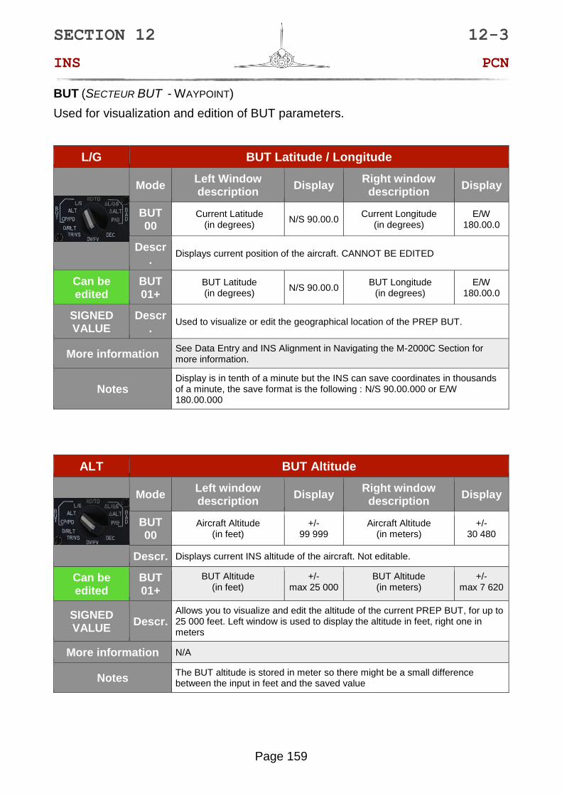
BUT (SECTEUR BUT - WAYPOINT)
Used for visualization and edition of BUT parameters.
L/G BUT Latitude / Longitude
Mode Left Window description
Display Right window
description Display
BUT 00
Current Latitude (in degrees)
N/S 90.00.0 Current Longitude
(in degrees) E/W
180.00.0
Descr.
Displays current position of the aircraft. CANNOT BE EDITED
Can be edited
BUT 01+
BUT Latitude (in degrees)
N/S 90.00.0 BUT Longitude
(in degrees) E/W
180.00.0
SIGNED VALUE
Descr.
Used to visualize or edit the geographical location of the PREP BUT.
More information See Data Entry and INS Alignment in Navigating the M-2000C Section for more information.
Notes Display is in tenth of a minute but the INS can save coordinates in thousands of a minute, the save format is the following : N/S 90.00.000 or E/W 180.00.000
ALT BUT Altitude
Mode
Left window description
Display Right window
description Display
BUT 00
Aircraft Altitude (in feet)
+/- 99 999
Aircraft Altitude (in meters)
+/- 30 480
Descr. Displays current INS altitude of the aircraft. Not editable.
Can be edited
BUT 01+
BUT Altitude (in feet)
+/- max 25 000
BUT Altitude (in meters)
+/- max 7 620
SIGNED VALUE
Descr. Allows you to visualize and edit the altitude of the current PREP BUT, for up to 25 000 feet. Left window is used to display the altitude in feet, right one in meters
More information N/A
Notes The BUT altitude is stored in meter so there might be a small difference between the input in feet and the saved value
SECTION 12 12-3
INS PCN
Page 160
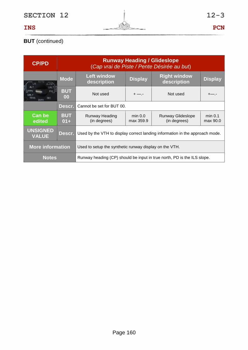
BUT (continued)
CP/PD Runway Heading / Glideslope
(Cap vrai de Piste / Pente Désirée au but)
Mode
Left window description
Display Right window
description Display
BUT 00
Not used + —.- Not used +—.-
Descr. Cannot be set for BUT 00.
Can be edited
BUT 01+
Runway Heading (in degrees)
min 0.0 max 359.9
Runway Glideslope (in degrees)
min 0.1 max 90.0
UNSIGNED VALUE
Descr. Used by the VTH to display correct landing information in the approach mode.
More information Used to setup the synthetic runway display on the VTH.
Notes Runway heading (CP) should be input in true north, PD is the ILS slope.

SECTION 12 12-3
INS PCN
Page 161
OTHER PARAMETERS
Used solely for data visualization.
D/RLT Distance and Bearing (Distance / Relevement)
Mode Left window description
Display Right window description
Display
BUT 00
Not used Blank True Heading (in degrees)
min 0.0 max 359.9
Descr. Right window shows true heading in degrees. Left window remains blank.
READ ONLY BUT 01+
Distance to BUT (in nautical miles)
min 0 max 409.60
Bearing to BUT (in degrees)
min 0.0 max 359.9
UNSIGNED VALUE
Descr. Displays the distance in nautical miles and bearing to PREP BUT or its BAD.
More information See IDN (HSI) in Navigating the M-2000C Section for more information.
Notes N/A
TR/VS Remaining Time / Ground Speed (Temps Restant / Vitesse Sol)
Mode Left window description
Display Right window description
Display
BUT 00
Not used Blank Ground Speed
(in knots) min 0
max 1990
Descr. Shows current Ground Speed in the right window. Left window remains blank.
READ ONLY BUT 01+
Remaining time to BUT (in minutes, seconds)
min 0 max 719.59
Ground Speed (in knots)
min 0 max 1990
UNSIGNED VALUE
Descr. Displays remaining time to reach current PREP BUT if ground speed remains constant. Right window shows current ground speed.
More information N/A
Notes
Ground speed is the only available speed value that is not affected by altitude, air density etc. Therefore, it is especially useful if mission briefing gives you ground speed of other assets, like tankers or planes you are required to escort.

SECTION 12 12-3
INS PCN
Page 162
OTHER PARAMETERS (continued)
DV/FV Wind Direction / Speed (Direction / Force du vent)
Mode
Left window description
Display Right window
description Display
BUT 00
Wind direction (in degrees)
min 0 max 359.9
Wind speed (in knots)
min 0 max 999
Descr. Displays current direction and speed of the wind.
READ ONLY BUT 01+
Wind direction (in degrees)
min 0 max 359.9
Wind speed (in knots)
min 0 max 999
UNSIGNED VALUE
Descr. Displays current direction and speed of the wind.
More information N/A
Notes
DEC Magnetic Variation (Declination)
Mode
Left window description
Display Right window
description Display
BUT 00
Magnetic variation (in degrees)
+/- 99.9
Not used blank
Descr. Displays magnetic variation in degrees between the True and Magnetic North.
Can be edited
BUT 01+
Magnetic variation (in degrees)
+/- 99.9
Not used blank
SIGNED VALUE
Descr. Displays magnetic variation in degrees between the True and Magnetic North.
More information See IDN (HSI) in Navigating the M-2000C Section for more information.
Notes If you enter value higher than maximum, the data in left and right LCD will revert to previous value. The magnetic variation should be editable but this is currently

SECTION 12 12-3
INS PCN
Page 163
BAD (Secteur But Additionnel - Offset Point)
USED FOR VISUALIZATION AND EDITION OF BAD PARAMETERS.
ρ/θ Setting BAD by polar Rho / Theta
Mode
Left window description
Display Right window
description Display
BUT 00
Not used + --.-- Not used ---.-
Descr. BAD cannot be set for Waypoint 0.
Can be edited
BUT 01+
BAD distance (in nautical Miles)
min 0.01 max 53.99
BAD Bearing (in degrees)
min 0.0 max 359.9
UNSIGNED VALUE
Descr. Introduced in the similar way to the bullseye calls, where Rho is the distance from the BUT in nautical miles, and Theta the true North bearing.
More information See Offset Points in Navigating the M-2000C Section for more information.
Notes If you enter value higher than maximum, the data in left and right LCD will revert to previous value.
ΔALT BAD ALTITUDE difference
Mode
Left window description
Display Right window
description Display
BUT 00
Not used ± -- --- Not used ± - ---
Descr. BAD cannot be set for Waypoint 0.
Can be edited
BUT 01+
BAD Altitude difference (in feet)
+/- max 24 999
BAD Altitude difference (in meters)
+/- max 7 619
SIGNED VALUE
Descr. Used to set the difference between the BUT altitude and the BAD altitude.
More information See OFFSET POINTS in Navigating the M-2000C Section for more information.
Notes

SECTION 12 12-3
INS PCN
Page 164
BAD (continued)
ΔL/ΔG Setting BAD by LAT / LONG difference
Mode
Left window description
Display Right window
description Display
BUT 00
Not used N/S
—.--.- Not used
E/W ---.--.-
Descr. BAD cannot be set for BUT 0.
Can be edited
BUT 01+
BAD Latitude (in meters)
N/S max 99 997
BAD Longitude (in meters)
E/W max 99
997
SIGNED VALUE
Descr. Enables you to set the targets coordinates using the distance in kilometers from the selected BUT to the North / South for ΔL and East / West for ΔG.
More information See OFFSET POINTS in Navigating the M-2000C Section for more information.
Notes The use of kilometers here is to help for exchanges with ground forces using those units.

SECTION 12 12-3
INS PCN
Page 165
Common to BUT and BAD
The RD and TD are parameters common to a BUT and its BAD.
RD/TD Desired Time and Route (Route Desiree / Temps Desire)
Mode Left window description
Display Right window
description Display
BUT 00
Ground Track (in degrees)
Min. 0 Max. 359.9
INS Chronometer (minutes, seconds)
Min 0 Max 399.9
Descr. The Ground Track gives you the exact current heading of your aircraft. INS Chronometer measures time since powering up the INS.
Can be edited
BUT 01+
Selected Bearing (in degrees)
Min. 0 Max. 359.9
Selected Time (minutes, seconds)
Min 0 Max 399.9
UNSIGNED VALUE
Descr.
Selected Bearing allows you to arrive at the given waypoint while flying at the predefined heading. Selected Time allows you to arrive at the given waypoint at a predefined moment in time.
More information See DESIRED TIME ON TARGET function in Navigating the M-2000C Section for more information.
Notes

SECTION 12 12-3
INS PCN
Page 166
DATA EDITION
The PCN uses three types of data:
• COORDINATES: Data that needs a cardinal direction (North or South, East or West).
• SIGNED DATA: Data that needs its sign to be specified (+ or -).
• UNSIGNED DATA: Data that don’t need a sign or cardinal direction and is assumed to be always positive.
Please refer to the DATA VISUALIZATION chapter for a full list of parameter data types.
To edit the data, you must:
1. Select the BUT to edit as PREP
2. Select the parameter to edit by rotating the parameter selector.
3. To select which top display window to edit:
• Left window: Press the 1 or 7 keys on the numeric keypad.
• Right window: Press the 3 or 9 keys on the numeric keypad.
4. Both the INS and EFF keys will light up, indicating that the PCN is in edit mode.
5. The selected window will show a series of dashes, indicating the number of digits to be entered.
If the data type is signed, both signs will be displayed on the left
If the data type is coordinates, the N/S for the left window and the E/W for the right window will be displayed.
6. If the data is not unsigned, the sign or cardinality need to selected first.
To select a sign:
• 1 or 7 for negative (-).
• 3 or 9 for positive (+).
To select a cardinality:
• 2 for North (N).
• 8 for South (S).
• 6 for East (E).
• 4 for West (W).

SECTION 12 12-3
INS PCN
Page 167
7. The data can then be enterd using the numeric keypad. Leading zeros are not needed in most cases. Be careful for the decimal point, one or two trailing zeros might be needed for round values.
The L/G data is a special case, the displayed data is shorter than the stored data. The PCN will display the coordinates up to a tenth of a minute while the INS can store up to a thousand of a minute. In order to input full coordinates, we need to type the hundred and thousand of a minute even if the PCN does not react to input. Entering a full longitude is the only case where a leading zero is needed when the degrees are under 100. Full coordinate entry is not necessary.
EXAMPLES
BUT COORDINATES
In this example we will enter the coordinates of Nellis Air Force Base: 36°14,129N 115°02,049W
1. We select the BUT we want to edit in PREP.
2. We set the PCN parameter selector to the L/G position.
3. To enter the latitude, we need to press the 1 or 7 key to edit the left window. The left window will display NS --.--.- and the INS and EFF keys will light up.
4. We first need to enter the latitude cardinality. In our example the latitude cardinality in north. We press the 2 key on the numeric keypad. The left window will display N --.--.-.
5. Then we need to enter the coordinates. In our example we type 3614129. The left window will display N 36.14.1. The last 2 digits are saved by the system but not displayed.
6. We press the INS key to insert the data into the INS memory.
7. To enter the longitude, we first need to press the 3 or 9 keys to edit the left window. The left window will display EW ---.--.- and the INS and EFF keys will light up.
8. We need to enter the longitude cardinality. In our example the longitude cardinality in west. We press the 4 key on the numeric keypad. The left window will display
W ---.--.-.
9. Then we need to enter the coordinates. In our example we type 11502049. The left window will display N 115.02.0. The last 2 digits are saved by the system but not displayed.
10. Press the INS key to insert the data into the INS memory.
11. If we made an error during the input we can reset the edited window with the EFF key.
Pressing the EFF key with an incorrect value or no value will exit the edition mode and reset the data to its previous value.
NOTE

SECTION 12 12-3
INS PCN
Page 168
12. Pressing the PREP key or changing the parameter knob position will cancel the edition.
BUT ALTITUDE
In this example we will enter the altitude of Nellis Air Force Base: 4867 ft
1. We select the BUT we want to edit in PREP.
2. We set the PCN parameter selector to the ALT position
3. We want to enter the altitude in feet so we need to press the 1 or 7 key to edit the left window. The left window will display +- ----- and the INS and EFF keys will light up.
4. We first need to enter the altitude sign. In our example the airbase altitude is above sea level, so it’s positive. We press the 1 key on the numeric keypad. The left window will display + -----.
5. Then we need to enter the altitude. In our example we type 4867. The left window will display + -4867. The leading zero is not needed.
6. Press the INS key to insert the data into the INS memory.
7. If we made an error during the input we can reset the edited window with the EFF key.
Pressing the EFF key with an incorrect value or no value will exit the edition mode and reset the data to its previous value.
8. Pressing the PREP key or changing the parameter knob position will cancel the edition.

SECTION 12 12-3
INS PCN
Page 169
BUT RD
In this example we will enter a RD:
085°
1. We select the BUT we want to edit in PREP.
2. We set the PCN parameter selector to the RD/TD position
3. We want to enter the RD so we need to press the 1 or 7 key to edit the left window. The left window will display ---.- and the INS and EFF keys will light up.
4. We need to enter the RD heading. In our example we type 850. The left window will display -85.0. The leading zero is not needed.
5. Press the INS key to insert the data into the INS memory.
6. If we made an error during the input we can reset the edited window with the EFF key.
Pressing the EFF key with an incorrect value or no value will exit the edition mode and reset the data to its previous value.
7. Pressing the PREP key or changing the parameter knob position will cancel the edition.
***

SECTION 12 12-3
INS PCN
Page 170
BUT
A BUT (But – waypoint) is navigation point composed of a latitude, a longitude, an altitude and other parameters that represent a location in space. They can be used for navigation, as a position fix point, as surface target, as a Bullseye or as a landing point.
The Mirage 2000C INS can store 20 of them (from 01 to 20) in addition to the BUT 00 that represent the aircraft’s current position.
All BUTs are can be selected at all times, by default if a BUT in not part of a flight plan or has been edited, its coordinates will be at 00.00.0 and 000.00.00 and the, the altitude will be at the maximum value and other parameters will be at zero.
The PCN is the only interface where the pilot can visualize, input and edit BUTs parameters.
PREP VS DEST
The PCN allows to select two different BUTs at the same time for different purpose:
• PREP (Préparation – Setup): Setting a BUT in PREP allows for the visualization and edition of its parameters. The PREP BUT informations are only displayed on the PCN and does not affect any other systems.
The PREP BUT is also the BUT of which the coordinates and altitude are going to be used when starting an alignment.
• DEST (Destination – Navigation): Setting a BUT in DEST allows for the navigation to this BUT. The DEST BUT informations are sent to the VTH and IDN for navigation use.
The selection of a BUT in PREP or DEST is done using the BUT selection keys:
1. Press the PREP or DEST key.
2. The pressed key will light up.
3. Use the numeric keypad to type the BUT number.
The BUT number always need to be two digits. In order to select the BUT 06 in DEST, press the DEST key and press 0 then 6 on the numeric keypad.
4. As you type the second number, the BUT will be selected and the pressed BUT key will turn off.
The BUTs can also be transferred between PREP and DEST and vice versa using the following procedure:
1. Press the BUT key you wish to be copied on by the other BUT selection.
2. The BUT key will light up.
3. Press the same key again.
NOTE

SECTION 12 12-3
INS PCN
Page 171
4. The BUT key turns off and the other selected BUT number will be copied on this BUT selection.
In order to copy the DEST BUT (06) in PREP, press the PREP key two times. The PREP BUT will now be the BUT 06.
The DEST BUT can be incremented or decremented using the DEST BUT Increment/Decrement buttons on the left of the front dash
BUT 00 VS BUT 01 - 20
The BUT 00 is not a navigation BUT but rather the current position of the aircraft. Not all of the data that is normally visualizable on the PCN can be viewed BUT 00. Also, some parameters display different information in BUT 00. Its parameters are not editable. Please refer to the DATA VISUALIZATION chapter for more informations on the parameter differences between BUT 00 and BUT 01 – 20.
The BUT 00 can only be selected as a PREP BUT, it can never be selected in DEST.
***
NOTE

SECTION 12 12-3
INS PCN
Page 172

SECTION 12 12-3
INS PCN
Page 173
BAD
A BAD is (Base Additionelle – Offset Waypoint) is waypoint of which is position is in reference to its parent BUT. A BAD cannot exist alone and is always linked to a BUT. They are most commonly used as surface targets or divert airfield. Each BUT can be parent to a BAD, that makes 20 BADs.
Three out of eleven positions on the PCN parameter selector are dedicated to setting up a BAD, under the BAD bracket.
BAD SETUP
1. Select the parent BUT in PREP.
2. Input the BAD offset distance from the BUT to the North/South and East/West in kilometers in the ΔL/ΔG parameter.
OR
Input the BAD bearing and distance from the BUT in nm in the ρ/θ parameter.
3. Input the altitude different between the BUT and the BAD in the ΔALT parameter. It can be positive or negative and be set in feet or meters.
BAD SELECTION
1. Select the parent BUT in DEST.
2. Press the BAD key.
3. The BAD key will light on to indicate that the DEST BAD is selected.
4. If the BAD is invalid, the BAD key will flash.
5. To deselect a BAD, press the BAD key again and the key will turn off.
More information on the BAD symbology on the VTH is available in the HUD DISPLAY
chapter.

SECTION 12 12-3
INS PCN
Page 174
MRQ
The Mirage 2000C INS is capable of saving up to three mark-points (MRQ – Marques). They take the BUT number 91, 92 and 93.
Once the 3 MRQs have been created they cannot be deleted or overwritten with a new MRQ. MRQs can only store coordinates and cannot be set as PREP, they can only be selected in DEST.
MRQ SETUP
1. Fly the aircraft over the point where you want to create the MQR.
2. Press the MRQ key on the PCN. It will light up with the VAL key to indicate that an MRQ slot is available and the PCN is in MRQ creation mode.
3. The PCN top window will show the MRQ coordinates for review.
4. To create the MQR press the VAL key. Both the MRQ and VAL keys will turn off and the MQT will be created.
5. If no MQR slot is available, the MRQ key will flash and the VAL key will stay off.
MQR SELECTION
An MRQ is selected just as a normal BUT using their number (91, 92 or 93) but they can only be selected in DEST. Trying to select an MRQ in PREP will reset PREP to the preciously selected BUT.

SECTION 12 12-5
INS ALIGNMENT
Page 175
12 – 5 - ALIGNMENT
The core of the INS houses a small platform bearing accelerometers and three gyroscopes. This platform needs to be calibrated in order to give accurate data and reduce drift rate. This calibration is called alignment.
The alignment process can be divided in 4 phases:
• PLATFORM CAGING AND SETUP, consisting of roughly setting up the platform horizontally and in azimuth, heating it up to operating temperature (70°) and spinning up the gyroscopes. This phase lasts about 35 seconds.
• ROUGH ALIGNMENT, consisting of recording the horizontal and azimuth bias of the platform and correcting them. This phase lasts about 20 seconds
• FAST GYROCOMPASS ALIGNMENT, same as the ROUGH ALIGNMENT but with a longer sampling, allowing finer correction and calculation of the platform heading using the earth rotation. This phase lasts about 80 seconds
• FINE GYROCOMPASS ALIGNMENT, consists of repeated FAST GYROCOMPASS
ALIGNMENT. This phase can be interrupted after the first FAST GYROCOMPASS
ALIGNMENT and lasts around 300 seconds.
Aligning an INS is a complex procedure that require a lot of precision. It is very important that is aircraft is not moved during the INS alignment or the procedure will be canceled and will need to be restarted.
While refueling and rearming the aircraft will not cancel the alignment process, however hanging heavy ordinances (wing fuel tanks or bombs on twin racks) will result in the aircraft moving on its suspensions due to the added weight. This can be enough to stop the process so refueling or rearming better be done before or after the alignment.
The INS allow 3 types of alignments:
• NORMAL ALIGNMENT (ALN - Alignement normal): Last 8 minutes and result in a 0,7nm/h drift rate.
• INTERRUPTED NORMAL ALIGNMENT (ALNI - Alignement normal interrompu): Last between 4 and 8 minutes and result in a drift rate between 4nm/h and 2nm/h.
• STORED HEADING ALIGNMENT (ALCM - Alignment sur cap mémorisé): Last 1 minute 30 seconds and result in a 3nm/h drift rate
The alignment type is selected on the PSM mode selector and stated using the VAL key on the PCN. When the alignment is in progress you can check its status using the STS position on the PSM operating mode selector. In ALN and ALNI the remaining time to the next class is also displayed.
The INS also need to know its initial location. This is done by setting a BUT with the current aircraft’s coordinates and altitude and starting the alignment process while having this BUT selected in PREP. BUT 00 to 20 can be used for this and as soon as the alignment has started the PREP BUT can be changed.
CAUTION

SECTION 12 12-5
INS ALIGNMENT
Page 176
NORMAL ALIGNMENT
The normal alignment (ALN – Alignment normal) is required at each cold start if the aircraft have been moved since the last time it stopped. This alignment lasts 8 minutes and result in a drift rate of about 0,7nm/h. This process combines all the available phase in order to achieve the most accurate alignment possible.
This alignment process is selected by turning the PSM mode selector in the ALN position, the ALN status light will flash to indicate that the alignment can be started. During the first half of the alignment the ALN status light is steady to indicate that the process is uninterruptible, after around 4 minutes and achieving the status 53, the ALN light will turn of and the PRET light will flash to indicate that the alignment is now interruptible. At the end of the 8 minutes and when the status reaches 00 the PRET light will turn steady to indicate that the INS is ready to go into NAV mode.
When the ALN is finished the INS will restart the fine gyrocompass alignment phase to reduce the drift rate until the PSM mode selector in turned to NAV mode. NOT FUNCTIONAL
Normal alignment timeline
1. PLATFORM CAGING AND SETUP.
2. ROUGH ALIGNMENT.
3. FAST GYROCOMPASS ALIGNMENT.
4. FINE GYROCOMPASS ALIGNMENT.
To execute a normal alignment:
1. Set the PSM Operational Mode to N.
2. Set the PSM Mode in VEI.
3. Select a BUT in PREP that contains the current aircraft’s coordinates and altitude.
In DCS, if the M-2000C Special option “Fast alignment (ALCM) ready” is not checked the BUT 00 coordinates won’t correspond to the aircraft position because it is assumed that the aircraft have been moved since the last time it was stopped.
Any BUT can be used for alignment but the most convenient one would be the BUT 20, as we seldom use a 20 waypoint flight plan.
4
0 1 2 3 4 6 7 8 5
1 3 2 4
9
92 99 76
96
Status
72
00 14
2
34 53
T min
2
NOTE
SECTION 12 12-5
INS ALIGNMENT
Page 177
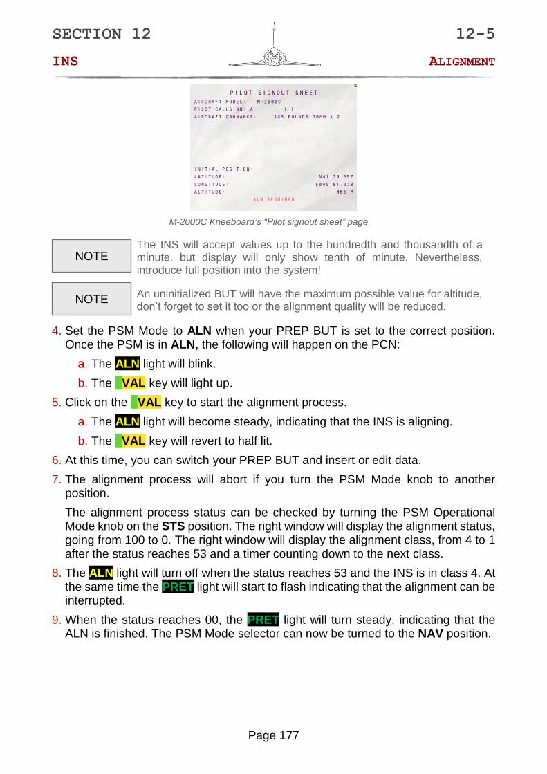
M-2000C Kneeboard’s “Pilot signout sheet” page
The INS will accept values up to the hundredth and thousandth of a minute. but display will only show tenth of minute. Nevertheless, introduce full position into the system!
An uninitialized BUT will have the maximum possible value for altitude, don’t forget to set it too or the alignment quality will be reduced.
4. Set the PSM Mode to ALN when your PREP BUT is set to the correct position. Once the PSM is in ALN, the following will happen on the PCN:
a. The ALN light will blink.
b. The VAL key will light up.
5. Click on the VAL key to start the alignment process.
a. The ALN light will become steady, indicating that the INS is aligning.
b. The VAL key will revert to half lit.
6. At this time, you can switch your PREP BUT and insert or edit data.
7. The alignment process will abort if you turn the PSM Mode knob to another position.
The alignment process status can be checked by turning the PSM Operational Mode knob on the STS position. The right window will display the alignment status, going from 100 to 0. The right window will display the alignment class, from 4 to 1 after the status reaches 53 and a timer counting down to the next class.
8. The ALN light will turn off when the status reaches 53 and the INS is in class 4. At the same time the PRET light will start to flash indicating that the alignment can be interrupted.
9. When the status reaches 00, the PRET light will turn steady, indicating that the ALN is finished. The PSM Mode selector can now be turned to the NAV position.
NOTE
NOTE
SECTION 12 12-5
INS ALIGNMENT
Page 178
INTERRUPTED NORMAL ALIGNMENT
The interrupted normal alignment (ALNI - Alignement normal interrompu), also called fast alignment (ALR – Alignement rapide), is a normal alignment that is stopped before its completion. This alignment lasts between 4 and 8 minutes and result in a drift rate between 4nm/h and 2nm/h. This process combines all the available phase in order to achieve the most accurate alignment possible.
This alignment process is selected by turning the PSM mode selector in the ALN position, the ALN status light will flash to indicate that the alignment can be started. During the first half of the alignment the ALN status light is steady to indicate that the process is uninterruptible, after around 4 minutes and achieving the status 53, the ALN light will turn of and the PRET light will flash to indicate that the alignment is now interruptible. At the end of the 8 minutes and when the status reaches 00 the PRET light will turn steady to indicate that the INS is ready to go into NAV mode.
When the ALN is finished the INS will restart the fine gyrocompass alignment phase to reduce the drift rate until the PSM mode selector in turned to NAV mode. NOT FUNCTIONAL
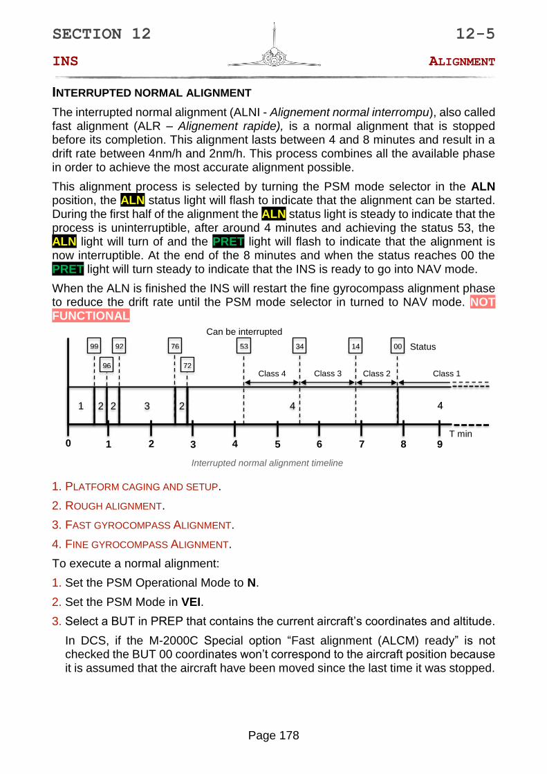
Interrupted normal alignment timeline
1. PLATFORM CAGING AND SETUP.
2. ROUGH ALIGNMENT.
3. FAST GYROCOMPASS ALIGNMENT.
4. FINE GYROCOMPASS ALIGNMENT.
To execute a normal alignment:
1. Set the PSM Operational Mode to N.
2. Set the PSM Mode in VEI.
3. Select a BUT in PREP that contains the current aircraft’s coordinates and altitude.
In DCS, if the M-2000C Special option “Fast alignment (ALCM) ready” is not checked the BUT 00 coordinates won’t correspond to the aircraft position because it is assumed that the aircraft have been moved since the last time it was stopped.
4
0 1 2 3 4 6 7 8 5
1 3 2 4
9
92 99 76
96
Status
72
00 14
2
34 53
T min
2
Class 4 Class 3 Class 2
Can be interrupted
Class 1

SECTION 12 12-5
INS ALIGNMENT
Page 179
You can use any BUT for use with the alignment but the most convenient one would be the BUT 20, as we seldom use a 20 waypoint flight plan.
M-2000C Kneeboard’s “Pilot signout sheet” page
The INS will accept values up to the hundredth and thousandth of a minute. but display will only show tenth of minute. Nevertheless, introduce full position into the system!
An uninitialized BUT will have the maximum possible value for altitude, don’t forget to set it too or the alignment quality will be reduced.
4. Set the PSM Mode to ALN when your PREP BUT is set to the correct position. Once the PSM is in ALN, the following will happen on the
PCN:
a. The ALN light will blink.
b. The VAL key will light up.
5. Click on the VAL key to start the alignment process.
a. The ALN light will become steady, indicating that the INS is aligning.
b. The VAL key will revert to half lit.
6. At this time, you can switch your PREP BUT and insert or edit data.
7. The alignment process will abort if you turn the PSM Mode knob to another position.
You can check the alignment process status by turning the PSM Operational Mode knob on the STS position. The right window will display the alignment status, going from 100 to 0. The right window will display the alignment class, from 4 to 1 after the status reaches 53 and a timer counting down to the next class.
8. The ALN light will turn off when the status reaches 53 and the INS is in class 4. At the same time the PRET light will start to flash indicating that the alignment can be interrupted.
9. When the status reaches 00, the PRET light will turn steady, indicating that the ALN is finished. The PSM Mode selector can now be turned to the NAV position.
NOTE NOTE
NOTE

SECTION 12 12-5
INS ALIGNMENT
Page 180
STORED HEADING ALIGNMENT
The stored heading alignment (ALCM – Alignment sur cap mémorisé) is a fast alignment method that can be used if the aircraft has not been moved since the last time its INS was stopped. The INS save its last heading when it is stopped and if the aircraft has not been moved the gyroscopes won’t have moved too far from their aligned position. This allows for less alignment phases resulting in a quicker procedure at the cost of increased drift rate due to gyroscope and accelerator errors not being canceled as well as in an ALN. This alignment lasts 1 minute 30 seconds and the resulting drift rate is dependent on the quality and time since the last normal alignment.
After a normal alignment followed by a standard flight and half a day rest for the aircraft, the drift rate will be about 3nm/h. Doing an ALCM just after a normal alignment or at the end of QRA duty will result a drift rate equivalent to the previous alignment rate.
This alignment process is selected by turning the PSM mode selector in the ALCM position, the ALN status light will flash to indicate that the alignment can be started. During the alignment the ALN status light is steady to indicate that the process is uninterruptible, after minute 30 seconds and achieving the status 00, the ALN light will turn of and the PRET light will turn steady to indicate that the alignment is finished and that the INS is ready to go into NAV mode.
Alternatively, the ALCM can be started by turning the PSM mode selector directly in the NAV position. NOT FUNCTIONAL
In DCS ALCM can be made available on ramp start by checking the “Fast alignment (ALCM) ready” special option checkbox. It will set the aircraft in à ALCM ready state and set the aircraft current coordinates on the BUT 00. The aircraft is then assumed to have been stopped a few hours before after an ALN followed by an uneventful flight. This option can also be used to start a normal alignment on PREP 00 as its coordinates will be correct.
Stored heading alignment timeline
1. PLATFORM CAGING AND SETUP.
2. ROUGH ALIGNMENT.
0 1 2
1 2
34 99
67 Status 00
2
T min
2

SECTION 12 12-5
INS ALIGNMENT
Page 181
To start a stored heading alignment:
1. Set the PSM Operational Mode in N.
2. Set the PSM Mode in VEI.
3. Check in the kneeboard that ALCM is possible as indicated by the red text “ALCM
AVAILABLE” below the aircraft starting coordinates.
M-2000C Kneeboard’s “Pilot signout sheet” page
4. Set the BUT 00 in PREP and check that its coordinates and altitude are correct to the aircraft current position.
5. Set the PSM Mode knob in ALCM position. Once the PSM is in this mode, the following will happen:
a. The ALN light will flash.
b. The VAL key will light up.
6. Click on the VAL key to start the alignment process.
a. The ALN light will become steady, indicating that the INS is aligning.
b. The VAL key will go dark.
Alternatively, you can turn the PSM mode selector in NAV mode, this will start the ALCM automatically without needing to press VAL. NOT FUNCTIONAL
7. The alignment process will abort if you turn the PSM mode selector from ALCM.
You can check the alignment process status by turning the PSM Operational Mode knob on the STS position. The right window will display the alignment status, going from 100 to 0. The right window will stay blank.
8. The ALN light will turn off and the PRET light will turn on when the alignment process has ended.
If the ALCM was started NAV, the PRET light will only turn on momentarily.
9. Now you can turn the PSM mode selector to NAV.

SECTION 12 12-6
INS POSITION FIX
Page 182
12 – 6 - POSITION FIX
INS drift can cause issues in all phases of a mission because as it is used for navigation and weapon employment. In order to correct the accumulated drift, the pilot can use a method called position fix (Recalage) that will provide the INS the means of correcting itself.
This method consists of providing the INS with the real position of a point in space of which it knows the coordinates. The INS can then compare the points real position with its stored position, deduce by how much it drifted and in which direction, and apply this difference to itself to correct the drift.
In the Mirage 2000 this is done using a BUT and a remarkable surface feature. The BUT needs to be place on the coordinates of the feature and at the altitude of the ground, then the pilot can use two methods to provide the position of this point to the INS :
• OVERFLY FIX (Recalage vertical): Consist of triggering the position fix when the aircraft is precisely over the surface feature.
• RADAR FIX (Recalage oblique): Consist of using the radar in TAS (Télémétrie Air-Sol – Radar ranging) to designate the surface feature through the VTH to get the slant range.
Both methods precisions are dependent of the overfly and designation fix accuracy, a moderate drift can be worsened by a fix on the wrong surface feature.
The INS system will refuse to validate a position fix that is greater than 15nm. Such case should not happen but if it does, the only way to fix the drift is to designate halfway between the BUT and the surface feature to cut the distance between them in half and then designate the surface feature.
OVERFLY FIX
This method is viable for low altitude flying and on relatively flat terrain as it is easier to estimate our position on the ground from low altitude.
To perform an overfly fix:
1. Select the fix BUT in DEST.
2. Fly the aircraft toward the fix BUT. As soon as the surface feature is in sight fly toward it and ignore the navigation cues.
3. When the aircraft is precisely over the surface feature, press the REC key on the PCN.
If the PCA is in NAV mode and MAV is not selected, the "Magic Unlock / Position update" HOTAS command will also trigger the fix procedure.
4. The REC key will turn on and the PCN top window will show the following information:
NOTE

SECTION 12 12-6
INS POSITION FIX
Page 183
• If the parameter selector is in the ΔL/ΔG position, the left window will show the difference in latitude and the right window will show the difference in longitude between the aircraft position at the time the procedure was triggered and the BUT position. The values will be given in nautical miles.
• If the parameter selector is in any other position, the left window will show the distance in nm and the right window will show the bearing of the aircraft position at the time the procedure was triggered and the BUT position.
5. If the difference between aircraft and landmark position is less than 15 nautical miles, the VAL key will turn on.
6. If the position difference between the fix and the BUT coordinate presented on the PCN is coherent, press the VAL key to accept the fix. The INS will apply the fix, the REC and VAL keys will turn off and the PCN will revert to normal operations.
7. If the difference between aircraft and landmark position is more than 15 nautical miles, the VAL key will remain dark and the REC key will flash. In this situation the only possible action is to reject the fix.
8. If the fix is not satisfactory, press the REC key. The INS will revert to normal operations.
***
SECTION 12 12-6
INS POSITION FIX
Page 184
RADAR FIX
This method is viable for high to low altitude and all kind of terrain. The only needed condition is line of sight to the surface feature.
To perform a radar fix:
1. Select the fix BUT in DEST.
2. Select OBL on the PCA. Check that the radar is working in TAS mode.
3. Fly the aircraft toward the fix BUT. As soon as the surface feature is in sight fly toward it and ignore the navigation cues.
4. Maneuver the aircraft to put the designation diamond over the surface feature.
5. Use the “Magic Slave/AG Designate/INS Position Update” HOTAS command to trigger the fix procedure.
6. The REC key will turn on and the PCN top window will show the following information:
• If the parameter selector is in the ΔL/ΔG position, the left window will show the difference in latitude and the right window will show the difference in longitude between the aircraft position at the time the procedure was triggered and the BUT position. The values will be given in kilometers.
• If the parameter selector is in any other position, the left window will show the distance in nm and the right window will show the bearing of the aircraft position at the time the procedure was triggered and the BUT position.
7. If the position difference between the fix and the BUT coordinate presented on the PCN is coherent, press the VAL key to accept the fix. The INS will apply the fix, the REC and VAL keys will turn off, the PCN will revert to normal operations and the radar will return to its previous mode.
8. If the difference between aircraft and landmark positions are more than 15 nautical miles, the VAL key will remain dark and the REC key will flash. In this situation the only possible action is to reject the fix.
9. If the fix is not satisfactory, press the REC key. The INS will revert to normal operations and the radar will return to its previous mode.
The radar fix will be cancelled if:
• The Master ARM switch is set to ARM.
• The PCA is set to POL mode.
• The PCA is set to APP mode.
• A weapon is selected on the PCA.


