Dedicated timers 5.1 SSAC, LLC. • 800-377-7722 • [email protected] • [email protected] • www.ssac.com • denotes a preferred product Section 5 Dedicated Timers Single Function Sequencer SQ3 & 4 -- Solid State Output .................5.154 Dual Function Delay on Make (ON Delay) Relay Output ..................................... 5.2 Delay on Make, Normally Closed Solid State Output ............................ 5.34 Delay on Break (OFF Delay) Relay Output ..................................... 5.42 Solid State Output ............................ 5.54 Single Shot (Pulse Former) Relay Output ..................................... 5.70 Solid State Output ............................ 5.84 Single Shot, Retriggerable (Watchdog, Zero Speed) Relay Output ............................................5.96 Interval (Impulse ON) Relay Output ............................................5.100 Solid State Output ...................................5.108 Recycling & Percentage Relay Output ............................................5.126 Solid State Output ...................................5.138 HVAC Timers Solid State Output TAC1 -- Anti Short Cycle Random Start ..5.160 T2D -- Anti Short Cycle, Random Start ...5.162 TAC4 -- Bypass Timing ............................5.164 TA -- Anti Short Cycle (DOB)....................5.166 TL -- Anti Short Cycle (DOB)....................5.168 CT -- Fan Delay........................................5.170 Vending Timers HRV -- Relay Output ................................5.172 THC/THS -- Solid State Output ...............5.94 KSPU -- Solid State Output .....................5.176 NHPU -- Solid State Output.....................5.178 Star Delta Motor Starting Delay on Make/Delay on Break TDMB -- Plug-In.......................................5.156 Delay on Make/Interval ESD5 -- Solid State..................................5.158 Sold by AA Electric 1-800-237-8274 • Lakeland, FL • Lawrenceville, GA • East Rutherford, NJ Web : www.A-Aelectric.com Email: [email protected]
SQ3 & 4 -- Solid State Output .................5.154
Dual Function
Delay on Make (ON Delay)Relay Output ..................................... 5.2 Delay on Make, Normally ClosedSolid State Output ............................ 5.34Delay on Break (OFF Delay)Relay Output ..................................... 5.42 Solid State Output ............................ 5.54Single Shot (Pulse Former)Relay Output ..................................... 5.70 Solid State Output ............................ 5.84
Single Shot, Retriggerable (Watchdog, Zero Speed)Relay Output ............................................5.96Interval (Impulse ON)Relay Output ............................................5.100Solid State Output ...................................5.108Recycling & PercentageRelay Output ............................................5.126Solid State Output ...................................5.138
HVAC Timers
Solid State OutputTAC1 -- Anti Short Cycle Random Start ..5.160T2D -- Anti Short Cycle, Random Start ...5.162TAC4 -- Bypass Timing ............................5.164TA -- Anti Short Cycle (DOB) ....................5.166TL -- Anti Short Cycle (DOB) ....................5.168CT -- Fan Delay ........................................5.170
Vending Timers
HRV -- Relay Output ................................5.172 THC/THS -- Solid State Output ...............5.94KSPU -- Solid State Output .....................5.176NHPU -- Solid State Output.....................5.178
Star Delta Motor Starting
Delay on Make/Delay on BreakTDMB -- Plug-In .......................................5.156Delay on Make/IntervalESD5 -- Solid State ..................................5.158
Sold by AA Electric 1-800-237-8274 • Lakeland, FL • Lawrenceville, GA • East Rutherford, NJ Web : www.A-Aelectric.com Email: [email protected]
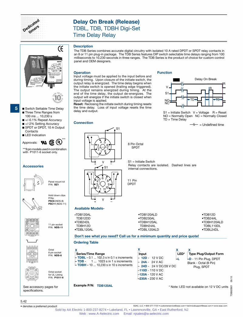
OperationInput voltage must be applied to the input before and during timing. Upon closure of the initiate switch, the output relay is energized. The time delay begins when the initiate switch is opened (trailing edge triggered). The output remains energized during timing. At the end of the time delay, the output de-energizes. The output will energize if the initiate switch is closed when input voltage is applied.Reset: Reclosing the initiate switch during timing resets the time delay. Loss of input voltage resets the time delay and output.
Switch Settable Time Delay Three Time Ranges from
100 ms ... 10,230 s +/-0.1% Repeat Accuracy +/-2% Setting Accuracy SPDT or DPDT, 10 A Output
Contacts LED Indication
Approvals:
Delay On Break (Release)TDBL, TDB, TDBH Digi-SetTime Delay Relay
Connection
Example P/N:
Function
Accessories
See accessory pages for specifications.
Panel mount kitP/N: BZ1
Hold down clipsP/Ns: PSC8 (NDS-8)PSC11 (NDS-11)
11 pin socketP/N: NDS-11
Octal8 pin socketP/N: NDS-8
The TDB Series combines accurate digital circuitry with isolated 10 A rated DPDT or SPDT relay contacts in an 8 or 11 pin plug-in package. The TDB Series features DIP switch selectable time delays ranging from 100 milliseconds to 10,230 seconds in three ranges. The TDB Series is the product of choice for custom control panel and OEM designers.
Delay On Break
S1 = Initiate Switch V = Voltage R = ResetNO = Normally Open NC = Normally ClosedTD = Time Delay
= Undened time
***8 pin models used in combination with P1011-6 socket only.
***8 Pin Octal
SPDT
11 Pin DPDT
Relay contacts are isolated. Dashed lines are internal connections.
X
– 12D - 12 V DC– 24A - 24 V AC– 24D - 24 V DC/28 V DC–110D - 110 V DC–120A - 120 V AC–230A - 230 V AC
Delay On Break (Release)TDBL, TDB, TDBH Digi-SetTime Delay Relay
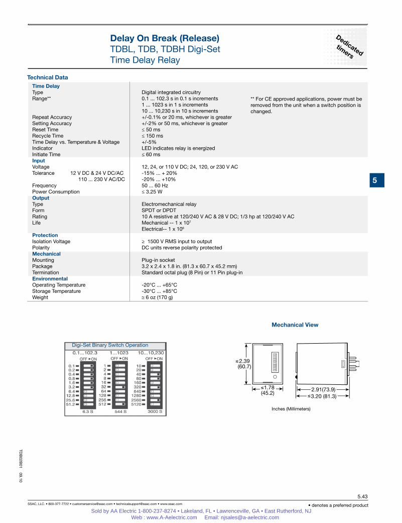
Inches (Millimeters)
Mechanical View
Digi-Set Binary Switch Operation
** For CE approved applications, power must be removed from the unit when a switch position is changed.
Time DelayType Digital integrated circuitryRange** 0.1 ... 102.3 s in 0.1 s increments 1 ... 1023 s in 1 s increments 10 ... 10,230 s in 10 s incrementsRepeat Accuracy +/-0.1% or 20 ms, whichever is greater Setting Accuracy +/-2% or 50 ms, whichever is greaterReset Time ≤ 50 msRecycle Time ≤ 150 ms Time Delay vs. Temperature & Voltage +/-5%Indicator LED indicates relay is energizedInitiate Time ≤ 60 msInputVoltage 12, 24, or 110 V DC; 24, 120, or 230 V ACTolerance 12 V DC & 24 V DC/AC -15% ... + 20% 110 ... 230 V AC/DC -20% ... +10%Frequency 50 ... 60 HzPower Consumption ≤ 3.25 WOutputType Electromechanical relayForm SPDT or DPDTRating 10 A resistive at 120/240 V AC & 28 V DC; 1/3 hp at 120/240 V ACLife Mechanical -- 1 x 10⁷ Electrical-- 1 x 10⁶
Protection Isolation Voltage ≥ 1500 V RMS input to outputPolarity DC units reverse polarity protectedMechanicalMounting Plug-in socketPackage 3.2 x 2.4 x 1.8 in. (81.3 x 60.7 x 45.2 mm)Termination Standard octal plug (8 Pin) or 11 Pin plug-inEnvironmentalOperating Temperature -20°C ... +65°CStorage Temperature -30°C ... +85°CWeight ≅ 6 oz (170 g)
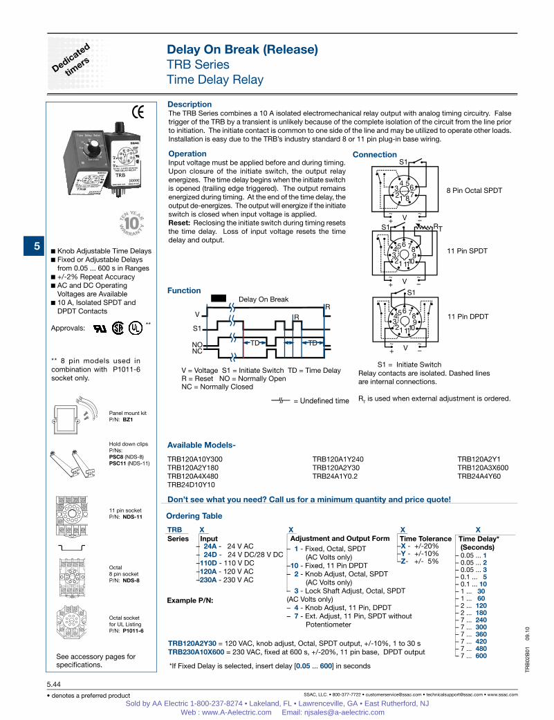
OperationInput voltage must be applied before and during timing. Upon closure of the initiate switch, the output relay energizes. The time delay begins when the initiate switch is opened (trailing edge triggered). The output remains energized during timing. At the end of the time delay, the output de-energizes. The output will energize if the initiate switch is closed when input voltage is applied.Reset: Reclosing the initiate switch during timing resets the time delay. Loss of input voltage resets the time delay and output.
Knob Adjustable Time Delays Fixed or Adjustable Delays
from 0.05 ... 600 s in Ranges +/-2% Repeat Accuracy AC and DC Operating
Voltages are Available 10 A, Isolated SPDT and
DPDT Contacts
Approvals:
Delay On Break (Release)TRB SeriesTime Delay Relay
Connection
Example P/N:
Function
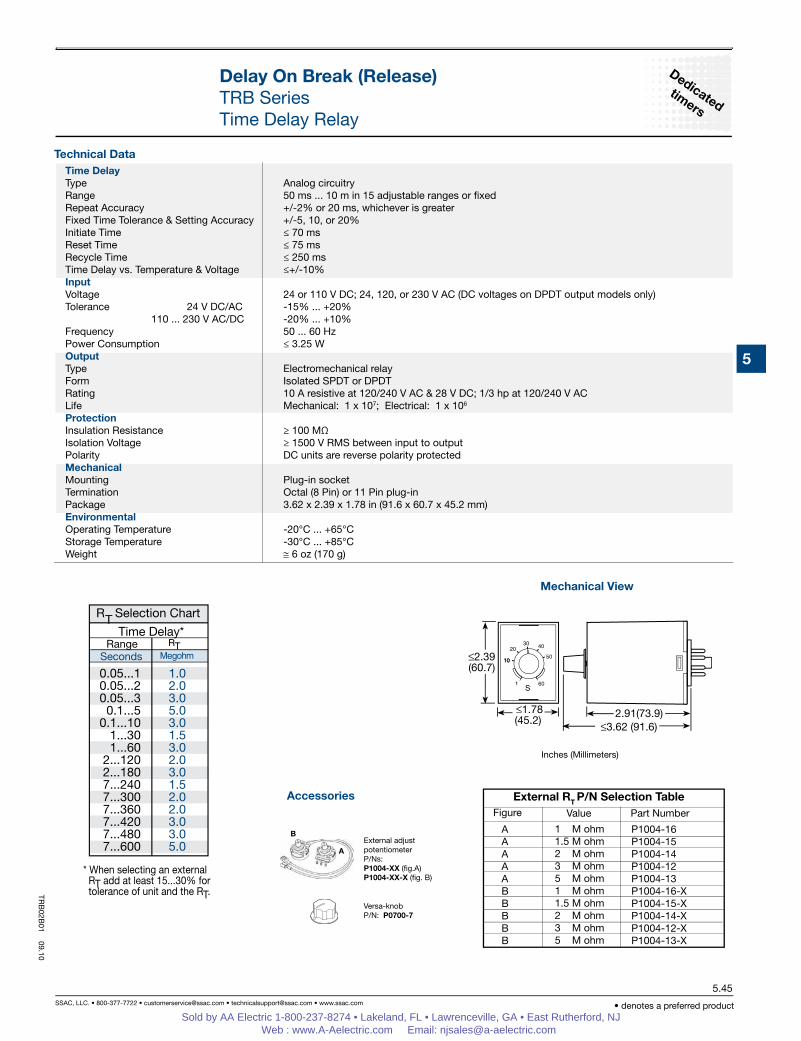
The TRB Series combines a 10 A isolated electromechanical relay output with analog timing circuitry. False trigger of the TRB by a transient is unlikely because of the complete isolation of the circuit from the line prior to initiation. The initiate contact is common to one side of the line and may be utilized to operate other loads. Installation is easy due to the TRB’s industry standard 8 or 11 pin plug-in base wiring.
V = Voltage S1 = Initiate Switch TD = Time Delay R = Reset NO = Normally Open NC = Normally Closed
Delay On Break
8 Pin Octal SPDT
11 Pin SPDT
11 Pin DPDT
Relay contacts are isolated. Dashed lines are internal connections.
RT is used when external adjustment is ordered.
– 24A - 24 V AC– 24D - 24 V DC/28 V DC–110D - 110 V DC–120A - 120 V AC–230A - 230 V AC
–X - +/-20%–Y - +/-10%–Z- +/- 5%
TRB X XSeries Input Adjustment and Output Form Time Tolerance Time Delay*
(Seconds)
*If Fixed Delay is selected, insert delay [0.05 ... 600] in seconds
** 8 pin models used in combination with P1011-6 socket only.
Time DelayType Analog circuitryRange 50 ms ... 10 m in 15 adjustable ranges or fixedRepeat Accuracy +/-2% or 20 ms, whichever is greaterFixed Time Tolerance & Setting Accuracy +/-5, 10, or 20%Initiate Time ≤ 70 msReset Time ≤ 75 msRecycle Time ≤ 250 msTime Delay vs. Temperature & Voltage ≤+/-10%InputVoltage 24 or 110 V DC; 24, 120, or 230 V AC (DC voltages on DPDT output models only)Tolerance 24 V DC/AC -15% ... +20% 110 ... 230 V AC/DC -20% ... +10%Frequency 50 ... 60 HzPower Consumption ≤ 3.25 WOutputType Electromechanical relayForm Isolated SPDT or DPDTRating 10 A resistive at 120/240 V AC & 28 V DC; 1/3 hp at 120/240 V ACLife Mechanical: 1 x 10⁷; Electrical: 1 x 10⁶
ProtectionInsulation Resistance ≥ 100 MΩ Isolation Voltage ≥ 1500 V RMS between input to output Polarity DC units are reverse polarity protectedMechanicalMounting Plug-in socketTermination Octal (8 Pin) or 11 Pin plug-inPackage 3.62 x 2.39 x 1.78 in (91.6 x 60.7 x 45.2 mm)EnvironmentalOperating Temperature -20°C ... +65°C Storage Temperature -30°C ... +85°CWeight ≅ 6 oz (170 g)
OperationInput voltage must be applied at all times prior to and during timing. Upon closure of the initiate switch, the output contacts transfer and remain transferred if no further action is taken. The LED is on steady. When the initiate switch is opened, the time delay is started. The LED flashes during timing. At the conclusion of the delay, the output contacts revert to their original unenergized position. Applying input voltage with the initiate switch closed will energize the load. Reset: Reclosing the initiate switch during timing resets the time delay. Loss of input voltage resets the time delay and output.
Knob Adjustable Time Delay Relay
Electronic Circuit with Electromechanical Relay
Popular AC & DC Operating Voltages
Industry Standard Octal Plug-in Connection
Time Delays to 600 s in 6 Ranges
+/-2% Repeat Accuracy +/-10% Factory Calibration LED Indication 10 A SPDT Relay Output
Approvals:
Delay On Break (Release)PRLB SeriesTime Delay Relay
Connection
Example P/N:
Function
Accessories
See accessory pages for specifications.
Octal8 pin socketP/N: NDS-8
DIN rail P/Ns: C103PM (Al)
Panel mount kitP/N: BZ1
Hold down clipsP/N: PSC8
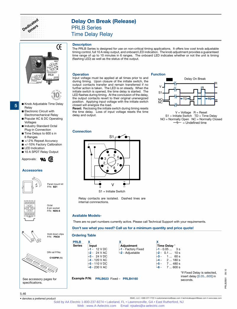
The PRLB Series is designed for use on non-critical timing applications. It offers low cost knob adjustable timing control, full 10 A relay output, and onboard LED indication. The knob adjustment provides a guaranteed time range of up to 10 minutes in 6 ranges. The onboard LED indicates whether or not the unit is timing (flashing LED) as well as the status of the output.
V = Voltage R = ResetS1 = Initiate Switch TD = Time Delay
NO = Normally Open NC = Normally Closed
Delay On Break
= Undened time
Relay contacts are isolated. Dashed lines are internal connnections.
Delay On Break (Release)PRLB SeriesTime Delay Relay
Inches (Millimeters)
Mechanical View
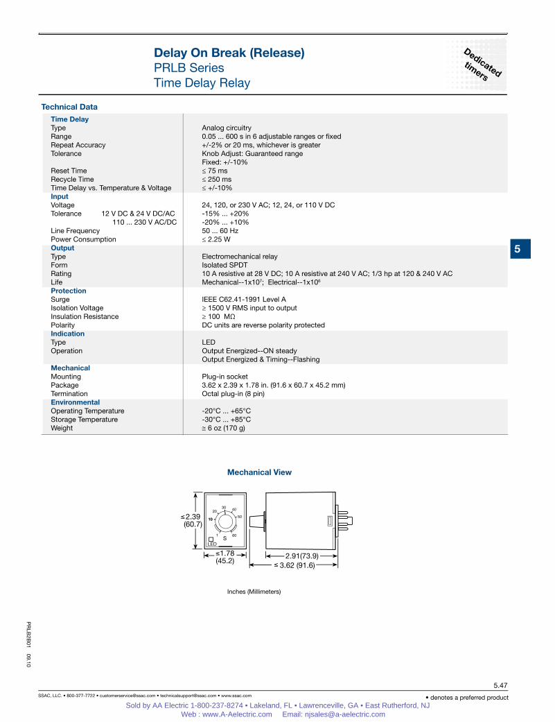
Time DelayType Analog circuitryRange 0.05 ... 600 s in 6 adjustable ranges or fixedRepeat Accuracy +/-2% or 20 ms, whichever is greaterTolerance Knob Adjust: Guaranteed range Fixed: +/-10%Reset Time ≤ 75 msRecycle Time ≤ 250 msTime Delay vs. Temperature & Voltage ≤ +/-10% InputVoltage 24, 120, or 230 V AC; 12, 24, or 110 V DCTolerance 12 V DC & 24 V DC/AC -15% ... +20% 110 ... 230 V AC/DC -20% ... +10%Line Frequency 50 ... 60 HzPower Consumption ≤ 2.25 WOutputType Electromechanical relayForm Isolated SPDTRating 10 A resistive at 28 V DC; 10 A resistive at 240 V AC; 1/3 hp at 120 & 240 V ACLife Mechanical--1x10⁷; Electrical--1x10⁶
ProtectionSurge IEEE C62.41-1991 Level AIsolation Voltage ≥ 1500 V RMS input to outputInsulation Resistance ≥ 100 MΩ Polarity DC units are reverse polarity protectedIndication Type LEDOperation Output Energized--ON steady Output Energized & Timing--FlashingMechanical Mounting Plug-in socketPackage 3.62 x 2.39 x 1.78 in. (91.6 x 60.7 x 45.2 mm) Termination Octal plug-in (8 pin)EnvironmentalOperating Temperature -20°C ... +65°CStorage Temperature -30°C ... +85°CWeight ≅ 6 oz (170 g)
PR
LB2B
01 09.10
Sold by AA Electric 1-800-237-8274 • Lakeland, FL • Lawrenceville, GA • East Rutherford, NJ Web : www.A-Aelectric.com Email: [email protected]
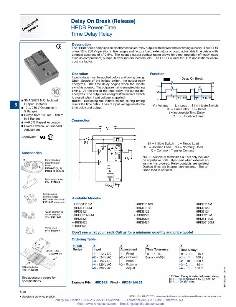
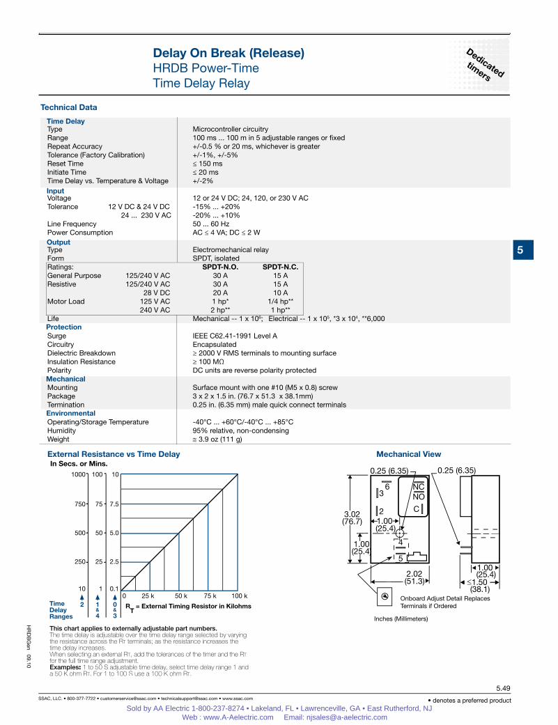
HRDB X X X X –1 - 12 V DC –1 - –A - +/-1% –0 - 0.1 ... 10 s –2 - 24 V AC –2 - Blank - +/-5% –1 - 1 ... 100 s –3 - 24 V DC –2 - 10 ... 1000 s –4 - 120 V AC –3 - –3 - 0.1 ... 10 m –6 - 230 V AC –4 - 1 ... 100 m
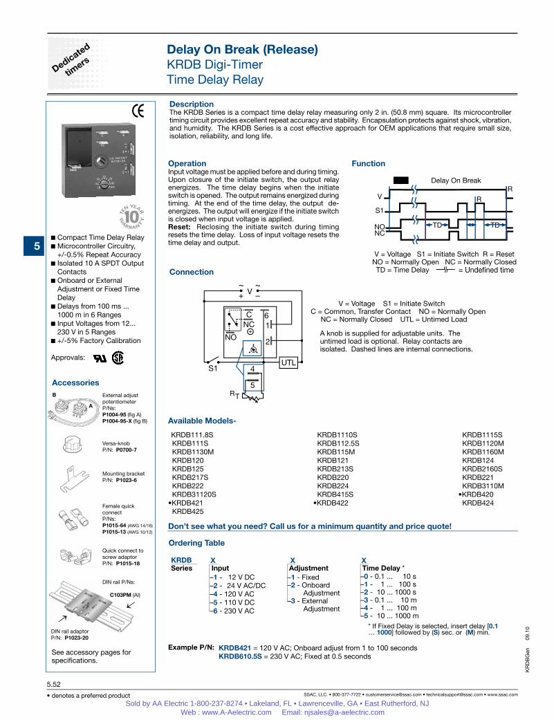
S1 = Initiate Switch L = Timed LoadUTL = Untimed Load NO = Normally Open C = Common, Transfer Contact
NOTE: A knob, or terminals 4 & 5 are only included on adjustable units. RT is used when external ad-justment is ordered. Relay contacts are isolated. Dashed lines are internal connections. The un-timed load is optional.
Accessories
DescriptionThe HRDB Series combines an electromechanical relay output with microcontroller timing circuitry. The HRDB offers 12 to 230 V operation in five ranges and factory fixed, external, or onboard adjustable time delays with a repeat accuracy of +/-0.5%. The isolated output contact rating allows for direct operation of heavy loads such as compressors, pumps, blower motors, heaters, etc. The HRDB is ideal for OEM applications where cost is a factor.
OperationInput voltage must be applied before and during timing. Upon closure of the initiate switch, the output relay energizes. The time delay begins when the initiate switch is opened. The output remains energized during timing. At the end of the time delay, the output de-energizes. The output will energize if the initiate switch is closed when input voltage is applied.Reset: Reclosing the initiate switch during timing resets the time delay. Loss of input voltage resets the time delay and output.
See accessory pages for specifications.
30 A SPDT N.O. Isolated Output Contacts
12 ... 230 V Operation in 5 Ranges
Delays from 100 ms ...100 m in 5 Ranges
+/-0.5% Repeat Accuracy Fixed, External, or Onboard
Adjustment Approvals:
Delay On Break (Release)HRDB Power-TimeTime Delay Relay
Delay On Break (Release)HRDB Power-TimeTime Delay Relay
Mechanical ViewExternal Resistance vs Time Delay
Inches (Millimeters)
Onboard Adjust Detail Replaces Terminals if Ordered
Time Delay
Output
Protection
Mechanical
Environmental
Input
Type Microcontroller circuitryRange 100 ms ... 100 m in 5 adjustable ranges or fixedRepeat Accuracy +/-0.5 % or 20 ms, whichever is greaterTolerance (Factory Calibration) +/-1%, +/-5%Reset Time ≤ 150 msInitiate Time ≤ 20 msTime Delay vs. Temperature & Voltage +/-2%
Voltage 12 or 24 V DC; 24, 120, or 230 V ACTolerance 12 V DC & 24 V DC -15% ... +20% 24 ... 230 V AC -20% ... +10%Line Frequency 50 ... 60 HzPower Consumption AC ≤ 4 VA; DC ≤ 2 W
Type Electromechanical relayForm SPDT, isolatedRatings: SPDT-N.O. SPDT-N.C.General Purpose 125/240 V AC 30 A 15 AResistive 125/240 V AC 30 A 15 A 28 V DC 20 A 10 AMotor Load 125 V AC 1 hp* 1/4 hp** 240 V AC 2 hp** 1 hp**Life Mechanical -- 1 x 10⁶; Electrical -- 1 x 10⁵, *3 x 10⁴, **6,000 Surge IEEE C62.41-1991 Level ACircuitry EncapsulatedDielectric Breakdown ≥ 2000 V RMS terminals to mounting surfaceInsulation Resistance ≥ 100 MΩ Polarity DC units are reverse polarity protected
Mounting Surface mount with one #10 (M5 x 0.8) screwPackage 3 x 2 x 1.5 in. (76.7 x 51.3 x 38.1mm)Termination 0.25 in. (6.35 mm) male quick connect terminals Operating/Storage Temperature -40°C ... +60°C/-40°C ... +85°CHumidity 95% relative, non-condensingWeight ≅ 3.9 oz (111 g)
HR
DB
Gen 09.10
Sold by AA Electric 1-800-237-8274 • Lakeland, FL • Lawrenceville, GA • East Rutherford, NJ Web : www.A-Aelectric.com Email: [email protected]
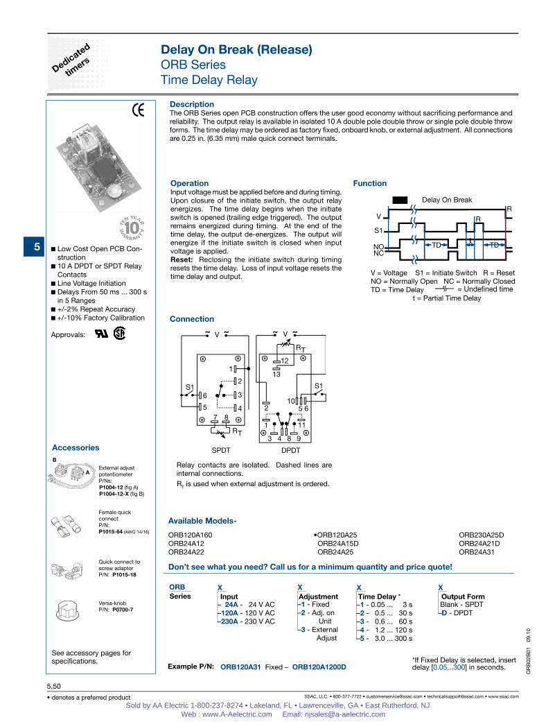
DescriptionThe ORB Series open PCB construction offers the user good economy without sacrificing performance and reliability. The output relay is available in isolated 10 A double pole double throw or single pole double throw forms. The time delay may be ordered as factory fixed, onboard knob, or external adjustment. All connections are 0.25 in. (6.35 mm) male quick connect terminals.
OperationInput voltage must be applied before and during timing. Upon closure of the initiate switch, the output relay energizes. The time delay begins when the initiate switch is opened (trailing edge triggered). The output remains energized during timing. At the end of the time delay, the output de-energizes. The output will energize if the initiate switch is closed when input voltage is applied.Reset: Reclosing the initiate switch during timing resets the time delay. Loss of input voltage resets the time delay and output.
See accessory pages for specifications.
Low Cost Open PCB Con-struction
10 A DPDT or SPDT Relay Contacts
Line Voltage Initiation Delays From 50 ms ... 300 s
in 5 Ranges +/-2% Repeat Accuracy +/-10% Factory Calibration
Approvals:
Delay On Break (Release)ORB SeriesTime Delay Relay
Connection
Example P/N:
Function
Female quickconnectP/N: P1015-64 (AWG 14/16)
Versa-knobP/N: P0700-7
Quick connect toscrew adaptorP/N: P1015-18
External adjustpotentiometerP/Ns:
Delay On Break
V = Voltage S1 = Initiate Switch R = ResetNO = Normally Open NC = Normally ClosedTD = Time Delay t = Partial Time Delay
= Undened time
SPDT DPDT
Relay contacts are isolated. Dashed lines are internal connections.RT is used when external adjustment is ordered.
V = Voltage S1 = Initiate Switch R = ResetNO = Normally Open NC = Normally ClosedTD = Time Delay t = Partial Time Delay
Technical Data
Delay On Break (Release)ORB SeriesTime Delay Relay
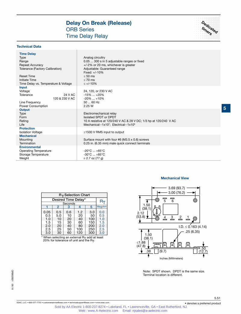
Mechanical View
Inches (Millimeters)
Note: SPDT shown. DPDT is the same size.Terminal location is different.
Time DelayType Analog circuitryRange 0.05 ... 300 s in 5 adjustable ranges or fixedRepeat Accuracy +/-2% or 20 ms, whichever is greaterTolerance (Factory Calibration) Adjustable: Guaranteed range Fixed: +/-10%Reset Time ≤ 50 msInitiate Time ≤ 70 msTime Delay vs. Temperature & Voltage ≤ +/-10%InputVoltage 24, 120, or 230 V ACTolerance 24 V AC -15% ... +20% 120 & 230 V AC -20% ... +10%Line Frequency 50 ... 60 HzPower Consumption 2.25 WOutputType Electromechanical relayForm Isolated SPDT or DPDTRating 10 A resistive at 120/240 V AC & 28 V DC; 1/3 hp at 120/240 V ACLife Mechanical--1x10⁷; Electrical--1x10⁶
ProtectionIsolation Voltage ≥1500 V RMS input to outputMechanical Mounting Surface mount with four #6 (M3.5 x 0.6) screwsTermination 0.25 in. (6.35 mm) male quick connect terminalsEnvironmentalOperating Temperature -20°C ... +65°CStorage Temperature -30°C ... +85°CWeight ≅ 2.7 oz (77 g)
OR
B02B
01 09.10
Sold by AA Electric 1-800-237-8274 • Lakeland, FL • Lawrenceville, GA • East Rutherford, NJ Web : www.A-Aelectric.com Email: [email protected]
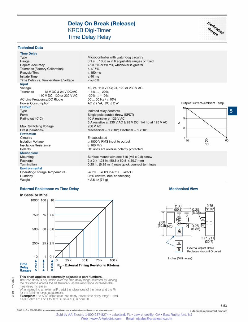
DescriptionThe KRDB Series is a compact time delay relay measuring only 2 in. (50.8 mm) square. Its microcontroller timing circuit provides excellent repeat accuracy and stability. Encapsulation protects against shock, vibration, and humidity. The KRDB Series is a cost effective approach for OEM applications that require small size, isolation, reliability, and long life.
OperationInput voltage must be applied before and during timing. Upon closure of the initiate switch, the output relay energizes. The time delay begins when the initiate switch is opened. The output remains energized during timing. At the end of the time delay, the output de-energizes. The output will energize if the initiate switch is closed when input voltage is applied.Reset: Reclosing the initiate switch during timing resets the time delay. Loss of input voltage resets the time delay and output.
See accessory pages for specifications.
Compact Time Delay Relay Microcontroller Circuitry,
+/-0.5% Repeat Accuracy Isolated 10 A SPDT Output
Contacts Onboard or External
Adjustment or Fixed Time Delay
Delays from 100 ms ... 1000 m in 6 Ranges
Input Voltages from 12... 230 V in 5 Ranges
+/-5% Factory Calibration
Approvals:
Delay On Break (Release)KRDB Digi-TimerTime Delay Relay
Delay On Break (Release)KRDB Digi-TimerTime Delay Relay
Mechanical View
Inches (Millimeters)
External Adjust Detail Replaces Knobs if Ordered
External Resistance vs Time Delay
Output Current/Ambient Temp.
Time DelayType Microcontroller with watchdog circuitryRange 0.1 s ... 1000 m in 6 adjustable ranges or fixedRepeat Accuracy +/-0.5% or 20 ms, whichever is greaterTolerance (Factory Calibration) ≤ +/-5%Recycle Time ≤ 150 msInitiate Time ≤ 40 msTime Delay vs. Temperature & Voltage ≤ +/-5% InputVoltage 12, 24, 110 V DC; 24, 120 or 230 V ACTolerance 12 V DC & 24 V DC/AC -15% ... +20% 110 V DC, 120 or 230 V AC -20% ... +10%AC Line Frequency/DC Ripple 50 ... 60 Hz / ≤ 10%Power Consumption AC ≤ 2 VA; DC ≤ 2 WOutputType Isolated relay contactsForm Single pole double throw (SPDT)Rating (at 40°C) 10 A resistive at 125 V AC 5 A resistive at 230 V AC & 28 V DC; 1/4 hp at 125 V ACMax. Switching Voltage 250 V ACLife (Operations) Mechanical -- 1 x 10⁷; Electrical -- 1 x 10⁵ ProtectionCircuitry EncapsulatedIsolation Voltage ≥ 1500 V RMS input to outputInsulation Resistance ≥ 100 MΩ Polarity DC units are reverse polarity protected MechanicalMounting Surface mount with one #10 (M5 x 0.8) screwPackage 2 x 2 x 1.21 in. (50.8 x 50.8 x 30.7 mm)Termination 0.25 in. (6.35 mm) male quick connect terminalsEnvironmental Operating/Storage Temperature -40°C ... +60°C/-40°C ... +85°CHumidity 95% relative, non-condensingWeight ≅ 2.6 oz (74 g)
KR
DB
Gen
09.10
Sold by AA Electric 1-800-237-8274 • Lakeland, FL • Lawrenceville, GA • East Rutherford, NJ Web : www.A-Aelectric.com Email: [email protected]
V = Voltage L = Load S1 = Initiate Switch TD = Time Delay R = Reset t = Incomplete Time Delay = Undened time
Accessories
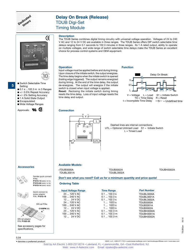
DescriptionThe TDUB Series combines digital timing circuitry with universal voltage operation. Voltages of 24 to 240 V AC and 12 to 24 V DC are available in three ranges. The TDUB Series offers DIP switch selectable time delays ranging from 0.1 seconds to 102.3 minutes in three ranges. Its 1 A rated output, ability to operate on multiple voltages, and wide range of switch selectable time delays make the TDUB Series an excellent choice for process control systems and OEM equipment.
OperationInput voltage must be applied before and during timing. Upon closure of the initiate switch, the output energizes. The time delay begins when the initiate switch is opened (trailing edge triggered). The output remains energized during timing. At the end of the time delay, the output de-energizes. The output will energize if the initiate switch is closed when input voltage is applied.Reset: Reclosing the initiate switch during timing resets the time delay. Loss of input voltage resets the time delay and output.
See accessory pages for specifications.
Switch Selectable Time Setting
0.1 s ...102.3 m in 3 Ranges +/- 0.5% Repeat Accuracy +/- 2% Setting Accuracy 1 A Solid State Output Encapsulated Wide Voltage Ranges
Approvals:
Delay On Break (Release)TDUB Digi-SetTiming Module
Connection
Function
Delay On Break
24 ... 120 V AC100 ... 240 V AC 12 ... 24 V DC 24 ... 120 V AC100 ... 240 V AC 12 ... 24 V DC 24 ... 120 V AC100 ... 240 V AC 12 ... 24 V DC
0.1 ... 102.3 s 0.1 ... 102.3 s 0.1 ... 102.3 s 1 ... 1023 s 1 ... 1023 s 1 ... 1023 s 0.1 ... 102.3 m 0.1 ... 102.3 m 0.1 ... 102.3 m
Delay On Break (Release)TDUB Digi-SetTiming Module
Mechanical View
Inches (Millimeters)
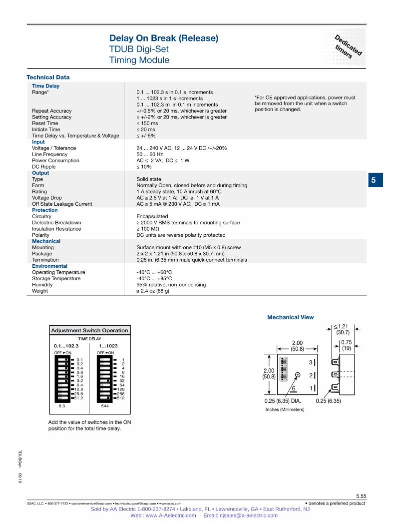
Add the value of switches in the ON position for the total time delay.
*For CE approved applications, power mustbe removed from the unit when a switchposition is changed.
Time DelayRange* 0.1 ... 102.3 s in 0.1 s increments 1 ... 1023 s in 1 s increments 0.1 ... 102.3 m in 0.1 m incrementsRepeat Accuracy +/-0.5% or 20 ms, whichever is greaterSetting Accuracy ≤ +/-2% or 20 ms, whichever is greaterReset Time ≤ 150 msInitiate Time ≤ 20 msTime Delay vs. Temperature & Voltage ≤ +/-5%InputVoltage / Tolerance 24 ... 240 V AC, 12 ... 24 V DC /+/-20%Line Frequency 50 ... 60 HzPower Consumption AC ≤ 2 VA; DC ≤ 1 WDC Ripple ≤ 10%OutputType Solid stateForm Normally Open, closed before and during timingRating 1 A steady state, 10 A inrush at 60°CVoltage Drop AC ≅ 2.5 V at 1 A; DC ≅ 1 V at 1 AOff State Leakage Current AC ≅ 5 mA @ 230 V AC; DC ≅ 1 mAProtectionCircuitry EncapsulatedDielectric Breakdown ≥ 2000 V RMS terminals to mounting surfaceInsulation Resistance ≥ 100 MΩ Polarity DC units are reverse polarity protectedMechanicalMounting Surface mount with one #10 (M5 x 0.8) screwPackage 2 x 2 x 1.21 in (50.8 x 50.8 x 30.7 mm)Termination 0.25 in. (6.35 mm) male quick connect terminalsEnvironmentalOperating Temperature -40°C ... +60°CStorage Temperature -40°C ... +85°CHumidity 95% relative, non-condensingWeight ≅ 2.4 oz (68 g)
TDU
BG
en 09.10
Sold by AA Electric 1-800-237-8274 • Lakeland, FL • Lawrenceville, GA • East Rutherford, NJ Web : www.A-Aelectric.com Email: [email protected]
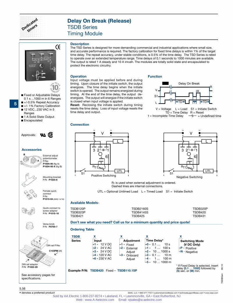
DescriptionThe TSD Series is designed for more demanding commercial and industrial applications where small size, and accurate performance is required. The factory calibration for fixed time delays is within 1% of the target time delay. The repeat accuracy, under stable conditions, is 0.5% of the time delay. The TSD Series is rated to operate over an extended temperature range. Time delays of 0.1 seconds to 1000 minutes are available. The output is rated 1 A steady and 10 A inrush. The modules are totally solid state and encapsulated to protect the electronic circuitry.
OperationInput voltage must be applied before and during timing. Upon closure of the initiate switch, the output energizes. The time delay begins when the initiate switch is opened. The output remains energized during timing. At the end of the time delay, the output de-energizes. The output will energize if the initiate switch is closed when input voltage is applied. Reset: Reclosing the initiate switch during timing resets the time delay. Loss of input voltage resets the time delay and output.
Function
See accessory pages for specifications.
Fixed or Adjustable Delays 0.1 s ...1000 m in 6 Ranges
V = Voltage L = Load S1 = Initiate Switch TD = Time Delay R = Reset
Delay On Break
X X X X –1 - 12 V DC –1 - –0 - 0.1 … 10 s –2 - 24 V AC –2 - –1 - 1 … 100 s –P - –3 - 24 V DC –2 - 10 … 1000 s –N - –4 - 120 V AC –3 - –3 - 0.1 … 10 m –6 - 230 V AC –4 - 1 ... 100 m –5 - 10 … 1000 m
Example P/N: TSDB420 Fixed – TSDB110.1SP
PositiveNegative
FixedExternalAdjustOnboardAdjust
* If Fixed Delay is selected, insert delay [0.1 … 1000] followed by (S) sec. or (M) min.
Switching Mode(V DC Only)
Series Input Adjustment Time Delay*
Positive Switching Negative Switching
RT is used when external adjustment is ordered.Dashed lines are internal connections.
B
Mounting bracketP/N: P1023-6
Female quick connectP/N:P1015-64 (AWG 14/16)
Quick connect toscrew adaptorP/N: P1015-18
External adjustpotentiometerP/Ns: P1004-95 (fig A)P1004-95-X (fig B)
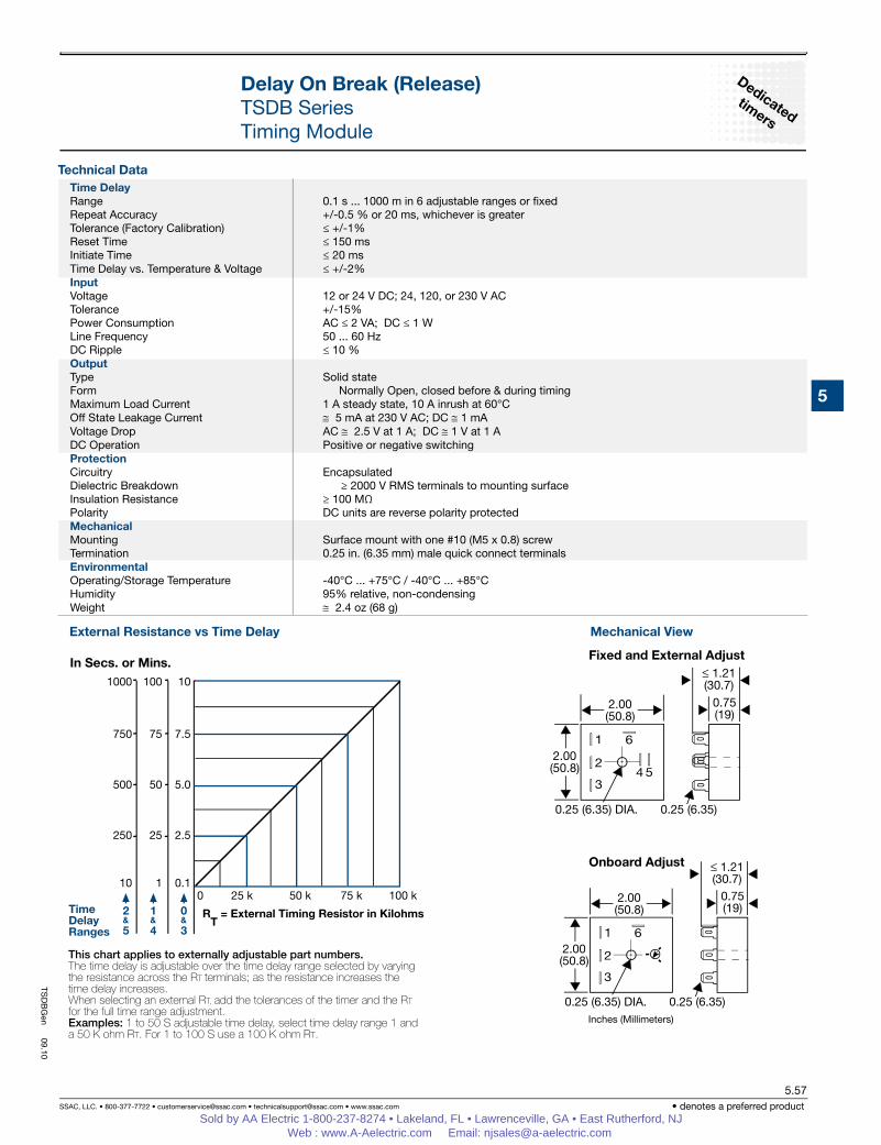
Time DelayRange 0.1 s ... 1000 m in 6 adjustable ranges or fixedRepeat Accuracy +/-0.5 % or 20 ms, whichever is greaterTolerance (Factory Calibration) ≤ +/-1%Reset Time ≤ 150 msInitiate Time ≤ 20 msTime Delay vs. Temperature & Voltage ≤ +/-2% InputVoltage 12 or 24 V DC; 24, 120, or 230 V ACTolerance +/-15%Power Consumption AC ≤ 2 VA; DC ≤ 1 W Line Frequency 50 ... 60 HzDC Ripple ≤ 10 %OutputType Solid stateForm Normally Open, closed before & during timingMaximum Load Current 1 A steady state, 10 A inrush at 60°COff State Leakage Current ≅ 5 mA at 230 V AC; DC ≅ 1 mA Voltage Drop AC ≅ 2.5 V at 1 A; DC ≅ 1 V at 1 A DC Operation Positive or negative switchingProtectionCircuitry EncapsulatedDielectric Breakdown ≥ 2000 V RMS terminals to mounting surfaceInsulation Resistance ≥ 100 MΩ Polarity DC units are reverse polarity protected MechanicalMounting Surface mount with one #10 (M5 x 0.8) screwTermination 0.25 in. (6.35 mm) male quick connect terminalsEnvironmentalOperating/Storage Temperature -40°C ... +75°C / -40°C ... +85°CHumidity 95% relative, non-condensingWeight ≅ 2.4 oz (68 g)
TSD
BG
en 09.10
Sold by AA Electric 1-800-237-8274 • Lakeland, FL • Lawrenceville, GA • East Rutherford, NJ Web : www.A-Aelectric.com Email: [email protected]
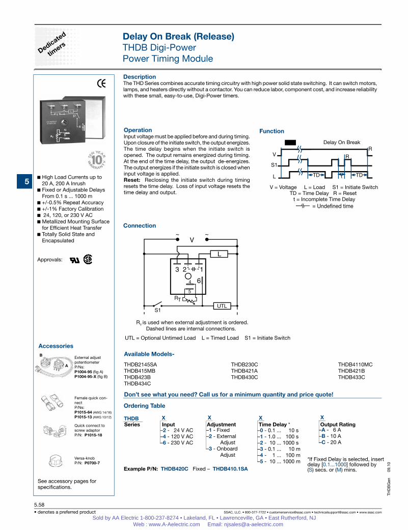
DescriptionThe THD Series combines accurate timing circuitry with high power solid state switching. It can switch motors, lamps, and heaters directly without a contactor. You can reduce labor, component cost, and increase reliability with these small, easy-to-use, Digi-Power timers.
OperationInput voltage must be applied before and during timing. Upon closure of the initiate switch, the output energizes. The time delay begins when the initiate switch is opened. The output remains energized during timing. At the end of the time delay, the output de-energizes. The output energizes if the initiate switch is closed when input voltage is applied.Reset: Reclosing the initiate switch during timing resets the time delay. Loss of input voltage resets the time delay and output.
Function
See accessory pages for specifications.
High Load Currents up to 20 A, 200 A Inrush
Fixed or Adjustable Delays From 0.1 s ... 1000 m
+/-0.5% Repeat Accuracy +/-1% Factory Calibration 24, 120, or 230 V AC Metallized Mounting Surface
for Efficient Heat Transfer Totally Solid State and
Encapsulated
Approvals:
Delay On Break (Release)THDB Digi-PowerPower Timing Module
Delay On Break (Release)THDB Digi-PowerPower Timing Module
Mechanical View
Inches (Millimeters)
External Resistance vs Time Delay
Fixed & External Adjust
Onboard Adjust
Time DelayRange 0.1 s ... 1000 m in 6 adjustable ranges or fixedRepeat Accuracy +/-0.5% or 20 ms, whichever is greaterTolerance (Factory Calibration) ≤ +/-1%Reset Time ≤ 150 msInitiate Time ≤ 20 msTime Delay vs. Temperature & Voltage ≤ +/-2%InputVoltage 24, 120, or 230 V ACTolerance +/-20%Line Frequency 50 ... 60 HzPower Consumption ≤ 2 VAOutputType Solid stateForm Normally Open, closed before & during timingMaximum Load Current Output Steady State Inrush** A 6 A 60 A B 10 A 100 A C 20 A 200 A Voltage Drop ≅ 2.5 V at rated currentOff State Leakage Current ≅ 5 mA at 230 V ACMinimum Load Current 100 mAProtectionCircuitry EncapsulatedDielectric Breakdown ≥ 2000 V RMS terminals to mounting surfaceInsulation Resistance ≥ 100 MΩ Mechanical Mounting ** Surface mount with one #10 (M5 x 0.8) screwTermination 0.25 in. (6.35 mm) male quick connect terminalsEnvironmental Operating/Storage Temperature -40°C ... +60°C / -40°C ... +85°CHumidity 95% relative, non-condensingWeight ≅ 3.9 oz (111 g)
**Must be bolted to a metal surface using the included heat sink compound. The maximum surface temperature is 90°C. Inrush: Non-repetitive for 16 ms.
THD
BG
en 09.10
Sold by AA Electric 1-800-237-8274 • Lakeland, FL • Lawrenceville, GA • East Rutherford, NJ Web : www.A-Aelectric.com Email: [email protected]
Series Input Adjustment Time Delay* Switching Mode (V DC Only)
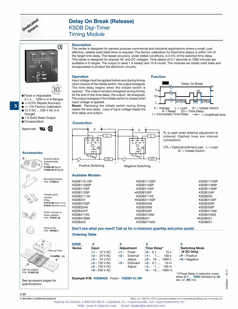
DescriptionThis series is designed for general purpose commercial and industrial applications where a small, cost effective, reliable solid state timer is required. The factory calibration for fixed time delays is within 5% of the target time delay. The repeat accuracy, under stable conditions, is 0.5% of the selected time delay. This series is designed for popular AC and DC voltages. Time delays of 0.1 seconds to 1000 minutes are available in 6 ranges. The output is rated 1 A steady and 10 A inrush. The modules are totally solid state and encapsulated to protect the electronic circuitry.
OperationInput voltage must be applied before and during timing. Upon closure of the initiate switch, the output energizes. The time delay begins when the initiate switch is opened. The output remains energized during timing. At the end of the time delay, the output de-energizes. The output energizes if the initiate switch is closed when input voltage is applied. Reset: Reclosing the initiate switch during timing resets the time delay. Loss of input voltage resets the time delay and output.
Function
See accessory pages for specifications.
Fixed or Adjustable 0.1 s ... 1000 m in 6 Ranges
+/-0.5% Repeat Accuracy +/- 5% Factory Calibration 12 V DC ... 230 V AC in 6
Ranges 1 A Solid State Output Encapsulated
Approvals:
Delay On Break (Release)KSDB Digi-TimerTiming Module
Connection
V = Voltage L = Load S1 = Initiate Switch R = Reset TD = Time Delay = Undened time
Delay On Break
Positive Switching Negative Switching
RT is used when external adjustment is ordered. Dashed lines are internal connections.
KSDB X X X X –1 - 12 V DC –1 - –0 - 0.1 … 10 s –2 - 24 V AC –2 - –1 - 1 … 100 s –P - Positive –3 - 24 V DC –2 - 10 … 1000 s –N - Negative –4 - 120 V AC –3 - –3 - 0.1 … 10 m –5 - 120 V DC –4 - 1 ... 100 m –6 - 230 V AC –5 - 10 … 1000 m Example P/N: KSDB420 Fixed – KSDB110.1SP
FixedExternalAdjustOnboardAdjust
* If Fixed Delay is selected, insert delay [0.1 … 1000] followed by (S) sec. or (M) min.
Delay On Break (Release)KSDB Digi-TimerTiming Module
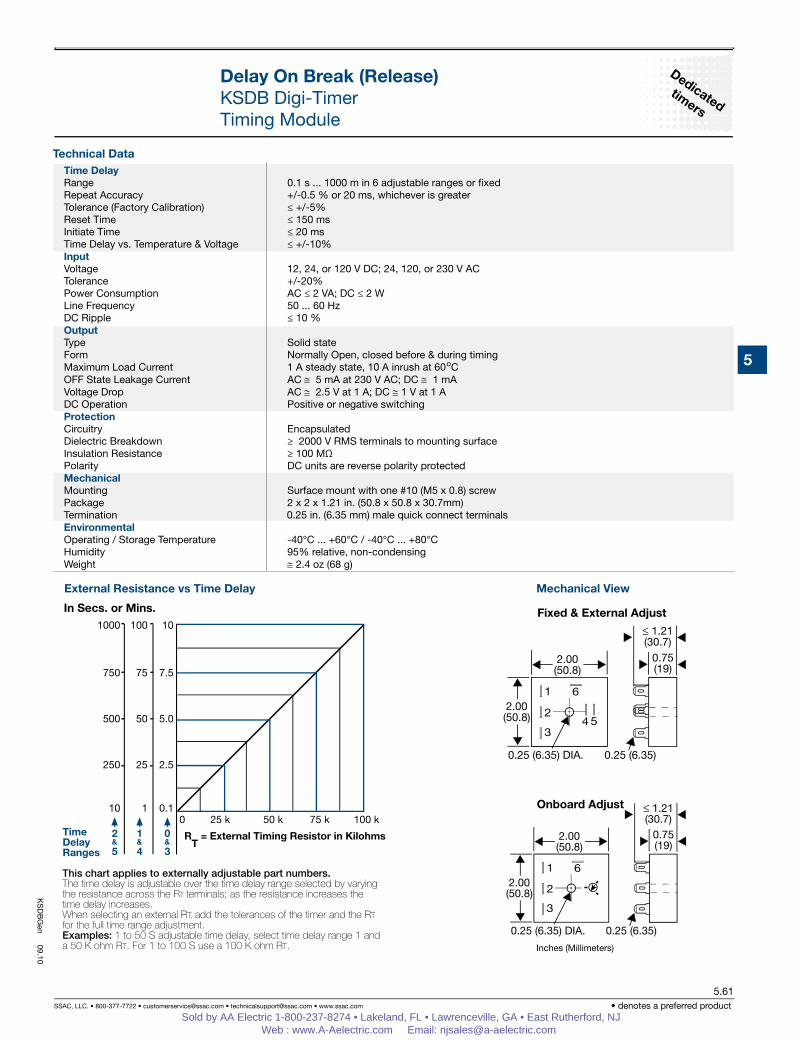
Mechanical ViewExternal Resistance vs Time Delay
Inches (Millimeters)
Onboard Adjust
Fixed & External Adjust
Time DelayRange 0.1 s ... 1000 m in 6 adjustable ranges or fixedRepeat Accuracy +/-0.5 % or 20 ms, whichever is greaterTolerance (Factory Calibration) ≤ +/-5%Reset Time ≤ 150 msInitiate Time ≤ 20 msTime Delay vs. Temperature & Voltage ≤ +/-10%InputVoltage 12, 24, or 120 V DC; 24, 120, or 230 V ACTolerance +/-20%Power Consumption AC ≤ 2 VA; DC ≤ 2 W Line Frequency 50 ... 60 HzDC Ripple ≤ 10 % OutputType Solid stateForm Normally Open, closed before & during timingMaximum Load Current 1 A steady state, 10 A inrush at 60oCOFF State Leakage Current AC ≅ 5 mA at 230 V AC; DC ≅ 1 mAVoltage Drop AC ≅ 2.5 V at 1 A; DC ≅ 1 V at 1 ADC Operation Positive or negative switching ProtectionCircuitry EncapsulatedDielectric Breakdown ≥ 2000 V RMS terminals to mounting surfaceInsulation Resistance ≥ 100 MΩ Polarity DC units are reverse polarity protectedMechanicalMounting Surface mount with one #10 (M5 x 0.8) screwPackage 2 x 2 x 1.21 in. (50.8 x 50.8 x 30.7mm)Termination 0.25 in. (6.35 mm) male quick connect terminalsEnvironmental Operating / Storage Temperature -40°C ... +60°C / -40°C ... +80°CHumidity 95% relative, non-condensingWeight ≅ 2.4 oz (68 g)
KS
DB
Gen
09.10
Sold by AA Electric 1-800-237-8274 • Lakeland, FL • Lawrenceville, GA • East Rutherford, NJ Web : www.A-Aelectric.com Email: [email protected]
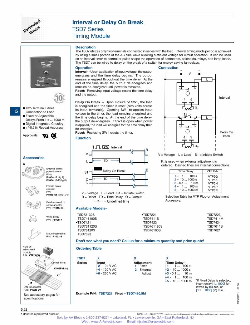
DescriptionThe TSD7 utilizes only two terminals connected in series with the load. Interval timing mode period is achieved by using a small portion of the AC sine wave allowing sufficient voltage for circuit operation. It can be used as an interval timer to control or pulse shape the operation of contactors, solenoids, relays, and lamp loads. The TSD7 can be wired to delay on the break of a switch for energy saving fan delays.
OperationInterval -- Upon application of input voltage, the output energizes and the time delay begins. The output remains energized throughout the time delay. At the end of the time delay, the output de-energizes and remains de-energized until power is removed.Reset: Removing input voltage resets the time delay and the output.
Delay On Break -- Upon closure of SW1, the load is energized and the timer is reset (zero volts across its input terminals). Opening SW1 re-applies input voltage to the timer, the load remains energized and the time delay begins. At the end of the time delay, the output de-energizes. If SW1 is open when power is applied, the load will energize for the time delay then de-energize.Reset: Reclosing SW1 resets the timer.
Two Terminal Series Connection to Load
Fixed or Adjustable Delays From 1 s ... 1000 m
Digital Integrated Circuitry +/-0.5% Repeat Accuracy
Approvals:
Interval or Delay On BreakTSD7 SeriesTiming Module
Connection
Example P/N:
Function
Accessories
See accessory pages for specifications.
RT is used when external adjustment is ordered. Dashed lines are internal connections.
Interval
Delay On Break
Delay On Break
V = Voltage L = Load S1 = Initiate SwitchR = Reset TD = Time Delay O = Output
Interval
= Undened time
Female quickconnectP/N:P1015-64 (AWG 14/16)
Versa-knobP/N: P0700-7
Mounting bracketP/N: P1023-6
Quick connect toscrew adaptorP/N: P1015-18
DIN rail P/Ns:
C103PM (Al)
DIN rail adaptorP/N: P1023-20
→
←
Plug-on adjustmentmoduleP/N: VTP(X)(X)
External adjustpotentiometerP/Ns: P1004-13 (fig A)P1004-13-X (fig B)
Interval or Delay On BreakTSD7 SeriesTiming Module
Inches (Millimeters)
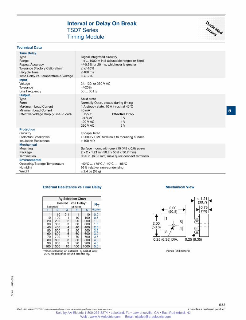
External Resistance vs Time Delay Mechanical View
Time DelayType Digital integrated circuitryRange 1 s ... 1000 m in 5 adjustable ranges or fixedRepeat Accuracy +/-0.5% or 20 ms, whichever is greaterTolerance (Factory Calibration) ≤ +/-10%Recycle Time ≤ 400 msTime Delay vs. Temperature & Voltage ≤ +/-2%InputVoltage 24, 120, or 230 V ACTolerance +/-20%Line Frequency 50 ... 60 HzOutputType Solid stateForm Normally Open, closed during timingMaximum Load Current 1 A steady state, 10 A inrush at 45°C Minimum Load Current 40 mAEffective Voltage Drop (VLine-VLoad) Input Effective Drop 24 V AC 3 V 120 V AC 4 V 230 V AC 6 VProtectionCircuitry EncapsulatedDielectric Breakdown ≥ 2000 V RMS terminals to mounting surfaceInsulation Resistance ≥ 100 MΩ Mechanical Mounting Surface mount with one #10 (M5 x 0.8) screwPackage 2 x 2 x 1.21 in. (50.8 x 50.8 x 30.7 mm)Termination 0.25 in. (6.35 mm) male quick connect terminalsEnvironmentalOperating/Storage Temperature -40°C ... +75°C / -40°C ... +85°CHumidity 95% relative, non-condensingWeight ≅ 2.4 oz (68 g)
TSD
72B11
09.10
Sold by AA Electric 1-800-237-8274 • Lakeland, FL • Lawrenceville, GA • East Rutherford, NJ Web : www.A-Aelectric.com Email: [email protected]
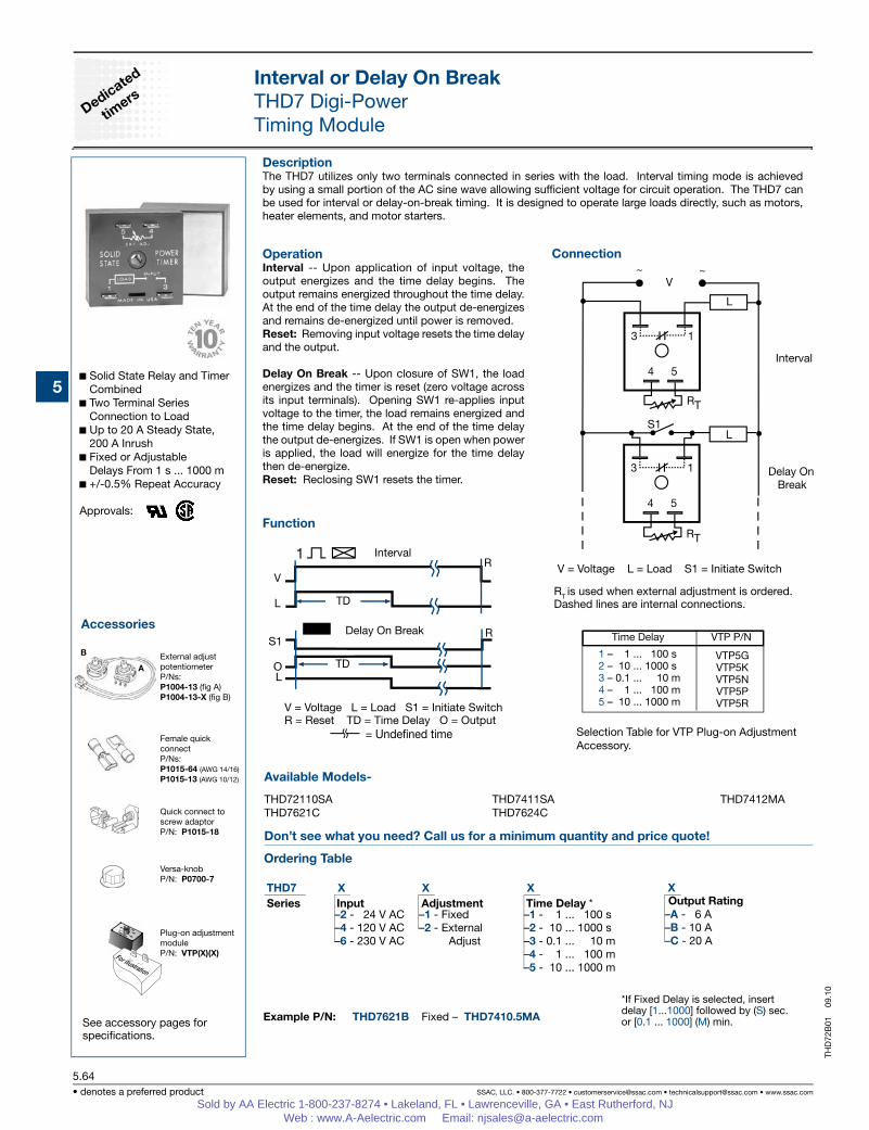
DescriptionThe THD7 utilizes only two terminals connected in series with the load. Interval timing mode is achieved by using a small portion of the AC sine wave allowing sufficient voltage for circuit operation. The THD7 can be used for interval or delay-on-break timing. It is designed to operate large loads directly, such as motors, heater elements, and motor starters.
OperationInterval -- Upon application of input voltage, the output energizes and the time delay begins. The output remains energized throughout the time delay. At the end of the time delay the output de-energizes and remains de-energized until power is removed.Reset: Removing input voltage resets the time delay and the output.
Delay On Break -- Upon closure of SW1, the load energizes and the timer is reset (zero voltage across its input terminals). Opening SW1 re-applies input voltage to the timer, the load remains energized and the time delay begins. At the end of the time delay the output de-energizes. If SW1 is open when power is applied, the load will energize for the time delay then de-energize.Reset: Reclosing SW1 resets the timer.
Solid State Relay and Timer Combined
Two Terminal Series Connection to Load
Up to 20 A Steady State, 200 A Inrush
Fixed or Adjustable Delays From 1 s ... 1000 m
+/-0.5% Repeat Accuracy
Approvals:
Interval or Delay On BreakTHD7 Digi-PowerTiming Module
Connection
Example P/N:
Function
Accessories
See accessory pages for specifications.
V = Voltage L = Load S1 = Initiate SwitchR = Reset TD = Time Delay O = Output = Undened time
Delay On Break
Interval
RT is used when external adjustment is ordered. Dashed lines are internal connections.
Interval
Delay On Break
External adjustpotentiometerP/Ns: P1004-13 (fig A)P1004-13-X (fig B)
Interval or Delay On BreakTHD7 Digi-PowerTiming Module
Inches (Millimeters)
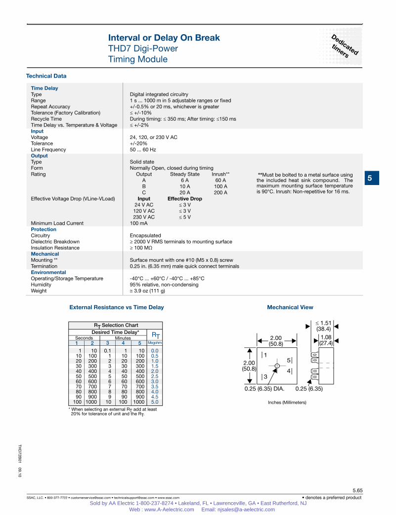
External Resistance vs Time Delay Mechanical View
**Must be bolted to a metal surface using the included heat sink compound. The maximum mounting surface temperature is 90°C. Inrush: Non-repetitive for 16 ms.
Time DelayType Digital integrated circuitryRange 1 s ... 1000 m in 5 adjustable ranges or fixedRepeat Accuracy +/-0.5% or 20 ms, whichever is greaterTolerance (Factory Calibration) ≤ +/-10%Recycle Time During timing: ≤ 350 ms; After timing: ≤150 msTime Delay vs. Temperature & Voltage ≤ +/-2%InputVoltage 24, 120, or 230 V ACTolerance +/-20%Line Frequency 50 ... 60 HzOutputType Solid stateForm Normally Open, closed during timingRating Output Steady State Inrush** A 6 A 60 A B 10 A 100 A C 20 A 200 A Effective Voltage Drop (VLine-VLoad) Input Effective Drop 24 V AC ≤ 3 V 120 V AC ≤ 3 V 230 V AC ≤ 5 VMinimum Load Current 100 mAProtectionCircuitry EncapsulatedDielectric Breakdown ≥ 2000 V RMS terminals to mounting surfaceInsulation Resistance ≥ 100 MΩ Mechanical Mounting ** Surface mount with one #10 (M5 x 0.8) screwTermination 0.25 in. (6.35 mm) male quick connect terminalsEnvironmentalOperating/Storage Temperature -40°C ... +60°C / -40°C ... +85°C Humidity 95% relative, non-condensingWeight ≅ 3.9 oz (111 g)
THD
72B01
09.10
Sold by AA Electric 1-800-237-8274 • Lakeland, FL • Lawrenceville, GA • East Rutherford, NJ Web : www.A-Aelectric.com Email: [email protected]
TSB X X X –2 - 24 V AC –1 - –1 - –4 - 120 V AC –2 - –2 - –6 - 230 V AC –3 - –4 -
Accessories
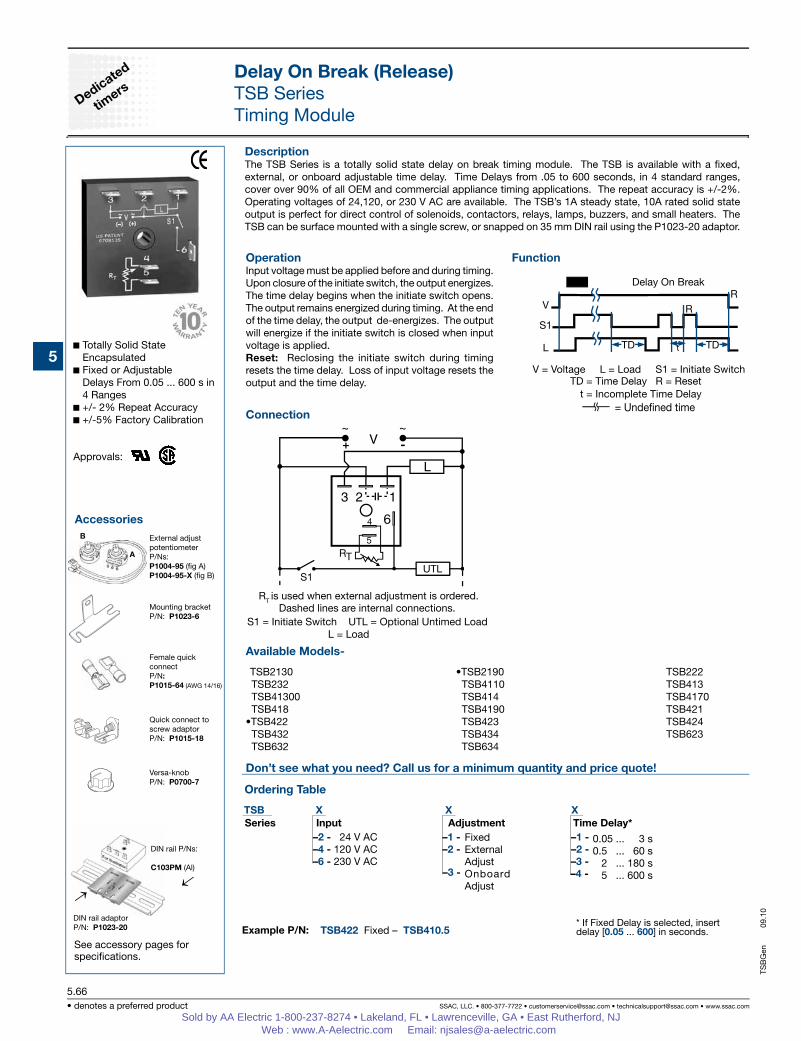
DescriptionThe TSB Series is a totally solid state delay on break timing module. The TSB is available with a fixed, external, or onboard adjustable time delay. Time Delays from .05 to 600 seconds, in 4 standard ranges, cover over 90% of all OEM and commercial appliance timing applications. The repeat accuracy is +/-2%. Operating voltages of 24,120, or 230 V AC are available. The TSB’s 1A steady state, 10A rated solid state output is perfect for direct control of solenoids, contactors, relays, lamps, buzzers, and small heaters. The TSB can be surface mounted with a single screw, or snapped on 35 mm DIN rail using the P1023-20 adaptor.
OperationInput voltage must be applied before and during timing. Upon closure of the initiate switch, the output energizes. The time delay begins when the initiate switch opens. The output remains energized during timing. At the end of the time delay, the output de-energizes. The output will energize if the initiate switch is closed when input voltage is applied. Reset: Reclosing the initiate switch during timing resets the time delay. Loss of input voltage resets the output and the time delay.
See accessory pages for specifications.
Totally Solid State Encapsulated
Fixed or Adjustable Delays From 0.05 ... 600 s in 4 Ranges
+/- 2% Repeat Accuracy +/-5% Factory Calibration
Approvals:
Delay On Break (Release)TSB SeriesTiming Module
Connection
Example P/N:
Function
B
Mounting bracketP/N: P1023-6
Female quick connectP/N:P1015-64 (AWG 14/16)
Quick connect toscrew adaptorP/N: P1015-18
External adjustpotentiometerP/Ns: P1004-95 (fig A)P1004-95-X (fig B)
Versa-knobP/N: P0700-7
→DIN rail adaptorP/N: P1023-20
←
A
DIN rail P/Ns:
C103PM (Al)
V = Voltage L = Load S1 = Initiate Switch TD = Time Delay R = Reset
= Undened time
Delay On Break
RT is used when external adjustment is ordered. Dashed lines are internal connections.
Series Input Adjustment Time Delay* FixedExternalAdjustOnboard Adjust
TSB422 Fixed – TSB410.5* If Fixed Delay is selected, insert delay [0.05 ... 600] in seconds.
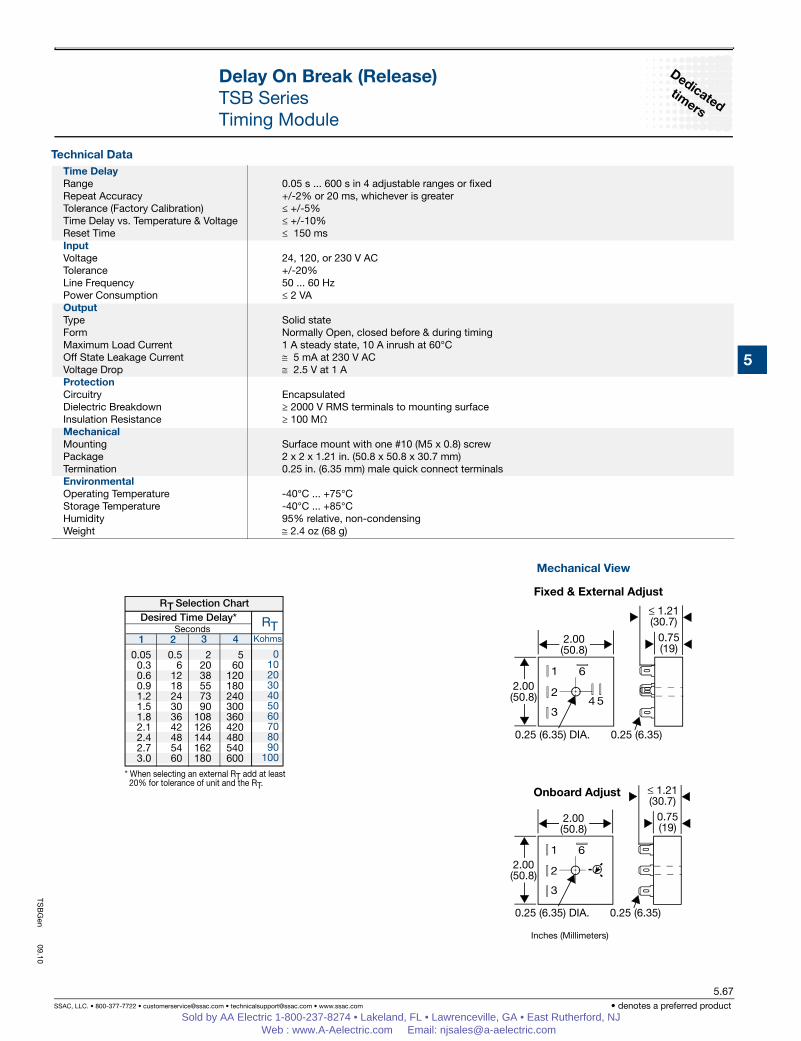
Time DelayRange 0.05 s ... 600 s in 4 adjustable ranges or fixedRepeat Accuracy +/-2% or 20 ms, whichever is greaterTolerance (Factory Calibration) ≤ +/-5%Time Delay vs. Temperature & Voltage ≤ +/-10% Reset Time ≤ 150 msInputVoltage 24, 120, or 230 V ACTolerance +/-20%Line Frequency 50 ... 60 HzPower Consumption ≤ 2 VA OutputType Solid stateForm Normally Open, closed before & during timingMaximum Load Current 1 A steady state, 10 A inrush at 60°COff State Leakage Current ≅ 5 mA at 230 V ACVoltage Drop ≅ 2.5 V at 1 A ProtectionCircuitry EncapsulatedDielectric Breakdown ≥ 2000 V RMS terminals to mounting surfaceInsulation Resistance ≥ 100 MΩ MechanicalMounting Surface mount with one #10 (M5 x 0.8) screwPackage 2 x 2 x 1.21 in. (50.8 x 50.8 x 30.7 mm)Termination 0.25 in. (6.35 mm) male quick connect terminalsEnvironmental Operating Temperature -40°C ... +75°CStorage Temperature -40°C ... +85°CHumidity 95% relative, non-condensingWeight ≅ 2.4 oz (68 g)
TSB
Gen
09.10
Sold by AA Electric 1-800-237-8274 • Lakeland, FL • Lawrenceville, GA • East Rutherford, NJ Web : www.A-Aelectric.com Email: [email protected]