30
Security manager’s guide to radar for site security applications NOT PROTECTIVELY MARKED NOT PROTECTIVELY MARKED Q

Security manager’s guideto radar for site securityapplications
NOT PROTECTIVELY MARKED
NOT PROTECTIVELY MARKED
Q

NOT PROTECTIVELY MARKED QinetiQ Proprietary
QINETIQ/IS/ICS/GU0903116 Page 2 QinetiQ Proprietary
NOT PROTECTIVELY MARKED
Administration page Customer Information
Customer reference number PO 7011563
Project title BFPS 7 Development of improved wide area surveillance radar
Customer Organisation CPNI
Customer contact TDF/21
Contract number L789-104-4
Milestone number N/A
Date due
Principal author
Martin Butcher 01684 895504
Alan Turing Bldg, Room 027, St Andrews Rd, Malvern, Worcester, WR14 3PS
Paul Fretwell 01684 895705
Alan Turing Bldg, Room 027, St Andrews Rd, Malvern, Worcester, WR14 3PS
Release Authority
Name Fiona McKinley
Post Project Manager
Date of issue 31 July 2009
Record of changes
Issue Date Detail of Changes
V1.0DRAFT June 2009 First draft
V1.1DRAFT July 2009 Changes after review of first draft by customer and internal peer review
V1.2DRAFT July 2009 Changes after customer review of version 1.1DRAFT.
V1.0 July 2009 First Issue

NOT PROTECTIVELY MARKED QinetiQ Proprietary
QINETIQ/IS/ICS/GU0903116 Page 3 QinetiQ Proprietary
NOT PROTECTIVELY MARKED
List of contents 1 Introduction 5
1.1 Background 5 1.2 Site Security Radar 6 1.3 Scope of Document 7 1.4 Structure of Document 8
2 Benefits of Radar for Site Security 9 3 Specifications 11
3.1 General Specification 11 3.2 Physical Requirements 13 3.3 Environmental Selection Criteria 14 3.4 Performance Requirements- Detection 17 3.5 Performance Requirements- False Alarms 18 3.6 Performance Requirements- Availability 19 3.7 Control and Indication 19 3.7.1 Stages in Radar Processing and Visualisation of Detected Targets 20 3.7.2 Staffing and Facilities 21 3.7.3 Alarm Handling 22 3.7.4 System Resilience 22 3.8 Documentation 22 3.9 Selecting a System 22
4 Installation 23 4.1 General 23 4.2 Commissioning 24
5 System maintenance 25 5.1 System Audit 25 5.2 Radar Maintenance 25 5.3 Site Maintenance 25
6 Reference/ Bibliography 26 7 Glossary of Terms and Definitions 27
7.1 Radar 27 7.2 Detection Zone 27 7.3 True Alarm 27 7.4 Detection Rate 27 7.5 False Alarm 27 7.6 False Alarm Rate 27 7.7 Detection Range 28 7.8 Radar Cross Section 28 7.9 Other Acronyms Used 28 Initial distribution list 29

NOT PROTECTIVELY MARKED QinetiQ Proprietary
QINETIQ/IS/ICS/GU0903116 Page 4 QinetiQ Proprietary
NOT PROTECTIVELY MARKED

NOT PROTECTIVELY MARKED QinetiQ Proprietary
1 Introduction
1.1 Background
The operational principle of radar is illustrated in Figure 1.
Figure 1: Schematic illustration of radar detection and object location
Radar detects the distance to an object by measuring how long it takes radio waves to travel from the radar transmitter, reflect off the target and travel back to the radar receiver. The range of the target can be easily calculated from this time interval. If the radar energy passes through the target (the optical analogy being a clear glass window) or is absorbed by the target, it will be difficult to detect using radar. The corollary of this is that targets (such as vehicles and pedestrians) that reflect radar energy strongly will be easier to detect using radar. The direction of the radio waves gives the bearing of the target and this, in conjunction with the range measurement, allows the position of the target to be determined.
Radar originated in the experimental work of Heinrich Hertz in the late 1880s. During World War II British and U.S. researchers developed a high-powered microwave radar system for military use. For a high level introduction to radar see chapter 1 of the Radar Handbook, edited by M. I. Skolnik, published by McGraw Hill [1].
Radar is used today in many civil applications including, but not limited to: Navigational aid for airplanes; Air traffic control; Maritime traffic monitoring; Monitoring local weather systems; Automotive (collision avoidance, parking aids etc); Detection of speeding on roads; Ground based surveillance.
QINETIQ/IS/ICS/GU0903116 Page 5 QinetiQ Proprietary
NOT PROTECTIVELY MARKED

NOT PROTECTIVELY MARKED QinetiQ Proprietary
1.2 Site Security Radar
This document will focus on the use of radar detection for ground-based surveillance.
Site surveillance radars can generally be divided into two categories: Radars designed to provide wide-area surveillance (often over a full 360
degrees) of open areas. This type of radar often employs a rotating antenna to scan its coverage, although there are examples of electronically-scanned (non-rotating) area surveillance radars;
Fill-in radars that provide fixed coverage over limited areas, including those designed to detect targets crossing a narrow barrier or perimeter. This type of radar typically has a fixed (also called a staring) antenna, with limited or no angular scanning capability.
Figure 2 illustrates the concept of providing wide area target detection using scanning radars, with shorter range staring radars deployed for in-fill where area coverage is not available or cannot be provided economically. Note that surveillance radars may give some through-fence detection capability, depending on the mesh size of the fence and the radar operating frequency.
Figure 2: Schematic showing the concept of using wide area and fill in radars to cover a secure site.
QINETIQ/IS/ICS/GU0903116 Page 6 QinetiQ Proprietary
NOT PROTECTIVELY MARKED
NOT PROTECTIVELY MARKED QinetiQ Proprietary
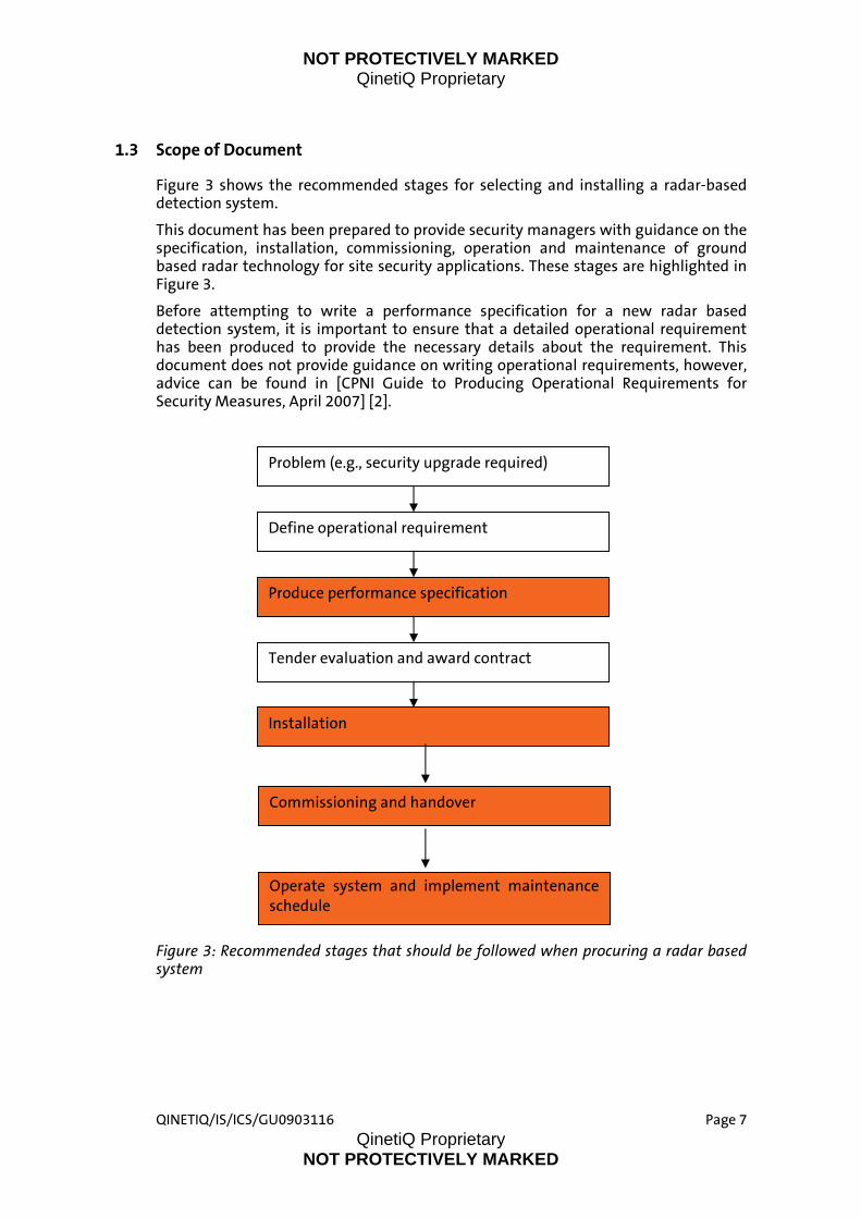
1.3 Scope of Document
Figure 3
Figure 3
Figure 3: Recommended stages that should be followed when procuring a radar based system
shows the recommended stages for selecting and installing a radar-based detection system.
This document has been prepared to provide security managers with guidance on the specification, installation, commissioning, operation and maintenance of ground based radar technology for site security applications. These stages are highlighted in
.
Before attempting to write a performance specification for a new radar based detection system, it is important to ensure that a detailed operational requirement has been produced to provide the necessary details about the requirement. This document does not provide guidance on writing operational requirements, however, advice can be found in [CPNI Guide to Producing Operational Requirements for Security Measures, April 2007] [2].
Problem (e.g., security upgrade required)
Define operational requirement
Produce performance specification
Installation
Tender evaluation and award contract
Commissioning and handover
Operate system and implement maintenance schedule
QINETIQ/IS/ICS/GU0903116 Page 7 QinetiQ Proprietary
NOT PROTECTIVELY MARKED
NOT PROTECTIVELY MARKED QinetiQ Proprietary
QINETIQ/IS/ICS/GU0903116 Page 8 QinetiQ Proprietary
NOT PROTECTIVELY MARKED
1.4 Structure of Document
The guide is structured as follows:
This section provides an introduction to radar technology, discusses the types of radar used for site security, identifies the key stages that should be followed when procuring a radar, and defines the scope of the guide.
Section 2 discusses the benefits of radar when used as part of an integrated site security system.
Section 3 provides guidance on how to specify the requirements for site security radar.
Section 4 provides guidance on installing and commissioning the radar and discusses the various physical and environmental factors that need to be taken into consideration.
Section 5 discusses the requirements for radar maintenance.
Section 6 lists reports/publications referenced in this document.
Section 7 is a glossary and list of definitions of technical terms used elsewhere in the document.

NOT PROTECTIVELY MARKED QinetiQ Proprietary
QINETIQ/IS/ICS/GU0903116 Page 9 QinetiQ Proprietary
NOT PROTECTIVELY MARKED
2 Benefits of Radar for Site Security Ground movement radars offer significant opportunities for improving site security in the UK. Research carried out by the Centre for the Protection of National Infrastructure (CPNI) has shown that radar technology can be a key element in the provision of enhanced detection and tracking of threats at many different types of national infrastructure. This section discusses the benefits of including radar in a protective security system.
Radar is most effective when used with complementary sensors such as Closed Circuit Television (CCTV), Perimeter Intruder Detection Systems (PIDS) and thermal imagers.
Like PIDS, radar can be used to monitor a site perimeter and detect intruders; but radar also has the capability to undertake area surveillance. As well as alerting the security operator to the presence of multiple potential threats, radar can determine the precise location of those threats and advanced systems can track their positions over time. This multiple target detection and tracking capability is available day or night.
Typically, alert zones may be defined, within which all targets detected by the radar will be flagged as potential threats and reported to the operator.
Advanced ground movement radars may provide a target classification capability, for example, they may be able to distinguish between pedestrians and vehicles. However, radar classification is rarely totally reliable. To verify whether the threat is genuine, the security operator will still need to verify the target. It is clearly more efficient to perform initial verification remotely, for example using CCTV, than to immediately despatch guards to investigate all targets. Target location data from the radar can be used to cue the appropriate camera system and direct it accurately at the target. Only when a target has been inspected and declared by the operator to be a potential threat, need guards be sent out. Hence, by including radar as part of an integrated sensor system, security managers can maximise the use of valuable guarding resources.
Although historically radars have been seen as expensive, complex and suitable for operation only by highly trained specialist staff, modern ground movement radars are different. They are relatively affordable, simple to operate, and can be integrated into existing security systems, with intuitive operator interfaces allowing straightforward control of the sensor and interpretation of the results.
Summarising, the main benefits of radar are: Radar can provide wide area and site perimeter monitoring; Radar can provide day/night all-weather detection and location of
multiple targets; When used in conjunction with CCTV, radar can provide effective alarm
cueing for security operators; Radars can be integrated into existing security systems, with intuitive
displays providing for easy sensor control and interpretation of results; No specialist technical knowledge is required by the operator; Radar is complementary to other security sensors and advanced radar
systems can provide even more information including:
NOT PROTECTIVELY MARKED QinetiQ Proprietary
QINETIQ/IS/ICS/GU0903116 Page 10 QinetiQ Proprietary
NOT PROTECTIVELY MARKED
Multiple target tracking; Automatic target classification.
To realize the benefits mentioned above it is important that the correct procedures are followed when specifying, selecting, installing, commissioning and testing the radar. Environmental factors and the characteristics of the site can all have a big impact on both the radar specification and final system performance. These factors are discussed in some detail in the remaining sections of this report, in order to provide the reader with the information needed to ensure that the radar system is well-matched to the site and its security requirements. The report focuses in particular on technical areas that would need to be considered when developing a detailed radar specification. However, a third party adviser could also be employed to assist in the generation of a specification to address a specific requirement.

NOT PROTECTIVELY MARKED QinetiQ Proprietary
QINETIQ/IS/ICS/GU0903116 Page 11 QinetiQ Proprietary
NOT PROTECTIVELY MARKED
3 Specifications
3.1 General Specification
The specification and selection of any radar depends on a number of different factors relating to the operational requirements and local circumstances:
Landscape and topographical features; Typical climatic conditions; Local environment; Whether or not there is a physical barrier and what it consists of; The nature of the security threat; Personnel movements on site; Response force arrangements; Alarm reporting methods; Integration with other types of equipment such as CCTV systems.
Specific points to be addressed in a radar system specification or other associated contract documentation include:
Specifying radar type- it may be acceptable to indicate a suitable radar technology; however users should refrain from specifying a particular system. If a particular radar system is specified then there can be problems in determining liability and responsibility if the system does not perform as required, provided it has been installed correctly;
Areas to be protected – including the length of perimeter fence to be covered and details of any barriers already there, in particular fence material and mesh size;
Physical requirements – see section 3.2; Environmental conditions – including weather conditions and wildlife,
see section 3.3; Threat types- a list of the target types that must be detected (eg
personnel and vehicles) and in what circumstances they must be detected (types of attack);
Acceptable levels of performance- Further information is provided in section 3.4;
Alarm verification. When a potential threat is detected it will be necessary to establish whether the threat is genuine and requires a response. This is typically achieved by obtaining CCTV footage of the indicated target location;
Operator interface. An appropriate display of radar tracks or detections should be presented to the operator; furthermore, details of map overlay requirements should be specified;
Integration. Information necessary to ensure that the radar can be integrated with existing systems, such as cameras, should be included in the specification;

NOT PROTECTIVELY MARKED QinetiQ Proprietary
QINETIQ/IS/ICS/GU0903116 Page 12 QinetiQ Proprietary
NOT PROTECTIVELY MARKED
Electrical requirements. Protective security radars usually require a mains or generator based power supply. The power supply requirements should be specified;
Standby power supplies. The standby power supply requirements should be specified, including the power rating of the back-up supply and the duration for which the system is required to operate in the event of a main supply outage;
Operating frequency. It is not generally appropriate to mandate the radar operating frequency. However, the specification should stipulate that the radar must operate within UK Office of Communications (OFCOM) frequency licensing requirements. Note also that although the radar frequency may lie within an OFCOM-licensed band, there may be limitations on the power levels that can be radiated within the band. For civilian radar use in the UK, the available frequency bands are centred around 24, 61, 77 and 94 GHz. For information on available frequency bands outside the UK, refer to the guidelines on spectrum management of the appropriate national control authority;
Radio interference/radiation. Radars can interfere with other Radio Frequency (RF) equipment, and, to a lesser extent, radar performance can be compromised by interference from external RF sources. In general, protective security radars radiate fairly low power. However, advice should be sought to establish whether there are any site-specific limitations on operating frequencies and radiated powers, beyond the usual OFCOM restrictions. If multiple radars operating on a common frequency are to be deployed as part of a sensor network, there could be potential for mutual interference. Specialist technical advice may be required to determine whether this is likely to be a problem. In practice, any mutual interference effects should be revealed during system commissioning and performance testing;
Safety. Radars are active RF devices and therefore limitations apply to exposure of personnel to their radiation. Protective security radars generally operate at low radiated powers. It will be necessary to specify that the sensor meets European safety directives for radiation hazards within its specified operational envelope. Suppliers of COTS radar equipment will have undertaken the necessary safety certification;
Access constraints/location details. The specification will need to give details of any restrictions on radar placement and factors that could affect the installation of the unit and supporting power/communications infrastructure. (In most cases cabling will need to be installed to link the radar head unit to the control station);
Visibility. The radar antenna will need to be mounted to provide line of sight visibility of the detection zone. Typically, a mechanically scanned radar will have an environmental cover (radome) fitted to protect the antenna. There is limited scope for camouflaging the antenna, and expert advice should be sought to ensure that any measures taken to do not attenuate the radar signal and hence reduce the radar's operational performance. Where a radome is fitted the rotation of a scanning radar may not be evident – hence although the sensor is visible, its function may not be obvious to lay personnel;

NOT PROTECTIVELY MARKED QinetiQ Proprietary
QINETIQ/IS/ICS/GU0903116 Page 13 QinetiQ Proprietary
NOT PROTECTIVELY MARKED
Contractual requirements. The specification may define minimum warranty requirements. It should state that commissioning tests will be performed prior to system acceptance.
To help ensure performance requirements are met and provide a baseline against which degradation in performance can be monitored, the purchaser should ensure that commissioning tests are performed prior to system acceptance. The performance of the radar under a range of different weather conditions and seasonally variable environmental conditions cannot be determined during a short commissioning test period. It is thus important that the system supplier/installer remains liable for inability to meet the required performance criteria during the warranty period.
3.2 Physical Requirements
While it is important not to compromise the system performance by including too many physical constraints, there are some significant design requirements that should be considered and may need to be included. The following factors can have a substantial impact on the suitability of a radar-based solution and should be included in the specification where relevant:
Ground and mounts – The mount or pedestal for the radar head must be very stable, otherwise angle measurement and target location accuracy will be degraded. Tall vegetation (e.g. long grass) growing near to the radar can degrade performance if it impedes the line of sight. Vegetation in the vicinity of a target also reflects incident radar energy, leading to increased noise and diminished sensitivity. It is recommended that grass areas be kept mown to reduce these effects. A body of water close to the radar (such as a lake) can reflect radar energy, leading to variations in detection performance and location accuracy for targets beyond the body of water;
The factors that determine whether a clear line of sight can be maintained across the detection zone include the height at which the radar antenna is deployed; the unevenness of the ground; surface type and the presence of structures above ground, both man-made (e.g. buildings, walls and parked vehicles) and natural (trees, hedges and bushes); and the characteristics of the radar beam. Sites with uneven or sloping terrain pose a particular challenge to ground surveillance radar;
Moving objects near to the radar can cause false alarms and/or a reduction in detection sensitivity. Examples include metal gates and vehicles on a busy road within the detection zone;
Buildings and other hard surfaces act as reflectors of radar energy and any large, flat metal surfaces (e.g. warehouse doors) act as particularly efficient mirror-reflectors. Targets moving in the vicinity of these buildings may generate multiple reflections which can increase radar false alarm rates, reduce detection performance and degrade location accuracy. It is therefore important that the installer is aware of the location of all large man made structures at the site, including the position of any large metal surfaces;
Required positional "accuracy". Radars measure target position – and the granularity of these location measurements in radar terminology is known as position resolution. The specification should define a maximum acceptable position resolution in two dimensions (eg 3 m x 3 m) . This is similar to the specification of zone lengths for a PIDS;
NOT PROTECTIVELY MARKED QinetiQ Proprietary
QINETIQ/IS/ICS/GU0903116 Page 14 QinetiQ Proprietary
NOT PROTECTIVELY MARKED
It is important to ensure that CCTV footprints overlap and jointly provide coverage of the entire detection zone, avoiding blind spots, to allow visual verification of targets detected by the radar;
The radar specification should define the minimum and maximum target velocities for pedestrians and vehicles. Although they may be able to detect slow and fast moving targets, protective security radars do not usually provide velocity measurements (although velocity can be estimated from the change in position over time). If the radar does provide independently obtained measurements of target velocity (not derived from position measurements) these can be used to improve target classification and aid tracking;
The measurement update rate needs to be specified. For the radar to be able to track agile ground targets reliably, update rates in the region of 1 Hz may be required. Research conducted by CPNI has shown that higher update rates, up to 2 Hz, can be beneficial if there is a requirement to track highly agile targets such as vehicles, particularly within 100 m range. Note that in general if the update rate increases (measurements are made more frequently) radar sensitivity and detection range decrease. The update rate should be fast enough to capture vehicle motion without compromising the detection of pedestrians.
The radar will be deployed outside. This is valuable hardware which is vulnerable to attack and needs to be on the secure side of any perimeter fence, or possibly (in the case of receiver hardware) buried in a weather-sealed container with an appropriate ingress protection (IP) rating. A PC and monitor are usually required to process the radar data and display it to the operator. These items may be located remotely inside a building and will generally require a cable connection to the radar. Any cabling should ideally be buried, to avoid trip hazards and make it less vulnerable to attack;
Multiple radars may need to be deployed to cover a site; the supplier/installer will decide if this is necessary. However, if there is a requirement to allow for future expansion of a site it may be appropriate to specify that the system should allow multiple radars to be networked to facilitate future extension of coverage.
3.3 Environmental Selection Criteria
Site security radars operate outside and must tolerate a wider range of conditions than sensors deployed within buildings. The specification should therefore include details of the environmental conditions (temperature, humidity, weather etc) in which the radar will be expected to operate.
In order to efficiently deploy a radar the installer/supplier will need to be cognizant of the details of the terrain, buildings, walls, roads, pathways, trees and vegetation at the site. This information should be obtained from a site survey undertaken by the supplier. Caution should be exercised if the purchaser supplies this information in the form of annotated topographic maps, as this may mean that the purchaser shares the risk should the system fail to perform as required.
Radar will experience changes to their operating environments during the course of a day (day/night variation in activity due to wildlife and the frequency of on-site personnel and vehicle movements) and seasonal variations due to leaf cover. Such
NOT PROTECTIVELY MARKED QinetiQ Proprietary
QINETIQ/IS/ICS/GU0903116 Page 15 QinetiQ Proprietary
NOT PROTECTIVELY MARKED
variations may give rise to an increase in false alarms in some circumstances. The installer should be made aware of any seasonal variations.
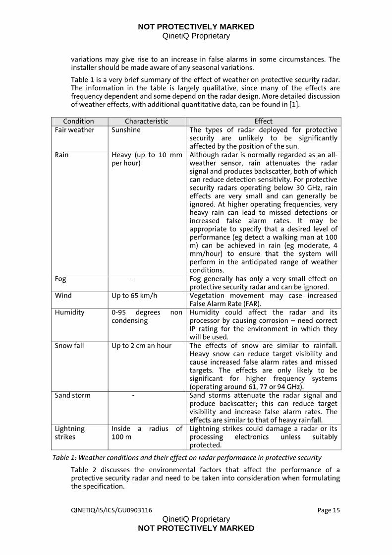
Table 1 is a very brief summary of the effect of weather on protective security radar. The information in the table is largely qualitative, since many of the effects are frequency dependent and some depend on the radar design. More detailed discussion of weather effects, with additional quantitative data, can be found in [1].
Condition Characteristic Effect
Fair weather Sunshine The types of radar deployed for protective security are unlikely to be significantly affected by the position of the sun.
Rain Heavy (up to 10 mm per hour)
Although radar is normally regarded as an all-weather sensor, rain attenuates the radar signal and produces backscatter, both of which can reduce detection sensitivity. For protective security radars operating below 30 GHz, rain effects are very small and can generally be ignored. At higher operating frequencies, very heavy rain can lead to missed detections or increased false alarm rates. It may be appropriate to specify that a desired level of performance (eg detect a walking man at 100 m) can be achieved in rain (eg moderate, 4 mm/hour) to ensure that the system will perform in the anticipated range of weather conditions.
Fog - Fog generally has only a very small effect on protective security radar and can be ignored.
Wind Up to 65 km/h Vegetation movement may case increased False Alarm Rate (FAR).
Humidity 0-95 degrees non condensing
Humidity could affect the radar and its processor by causing corrosion – need correct IP rating for the environment in which they will be used.
Snow fall Up to 2 cm an hour The effects of snow are similar to rainfall. Heavy snow can reduce target visibility and cause increased false alarm rates and missed targets. The effects are only likely to be significant for higher frequency systems (operating around 61, 77 or 94 GHz).
Sand storm - Sand storms attenuate the radar signal and produce backscatter; this can reduce target visibility and increase false alarm rates. The effects are similar to that of heavy rainfall.
Lightning strikes
Inside a radius of 100 m
Lightning strikes could damage a radar or its processing electronics unless suitably protected.
Table 1: Weather conditions and their effect on radar performance in protective security
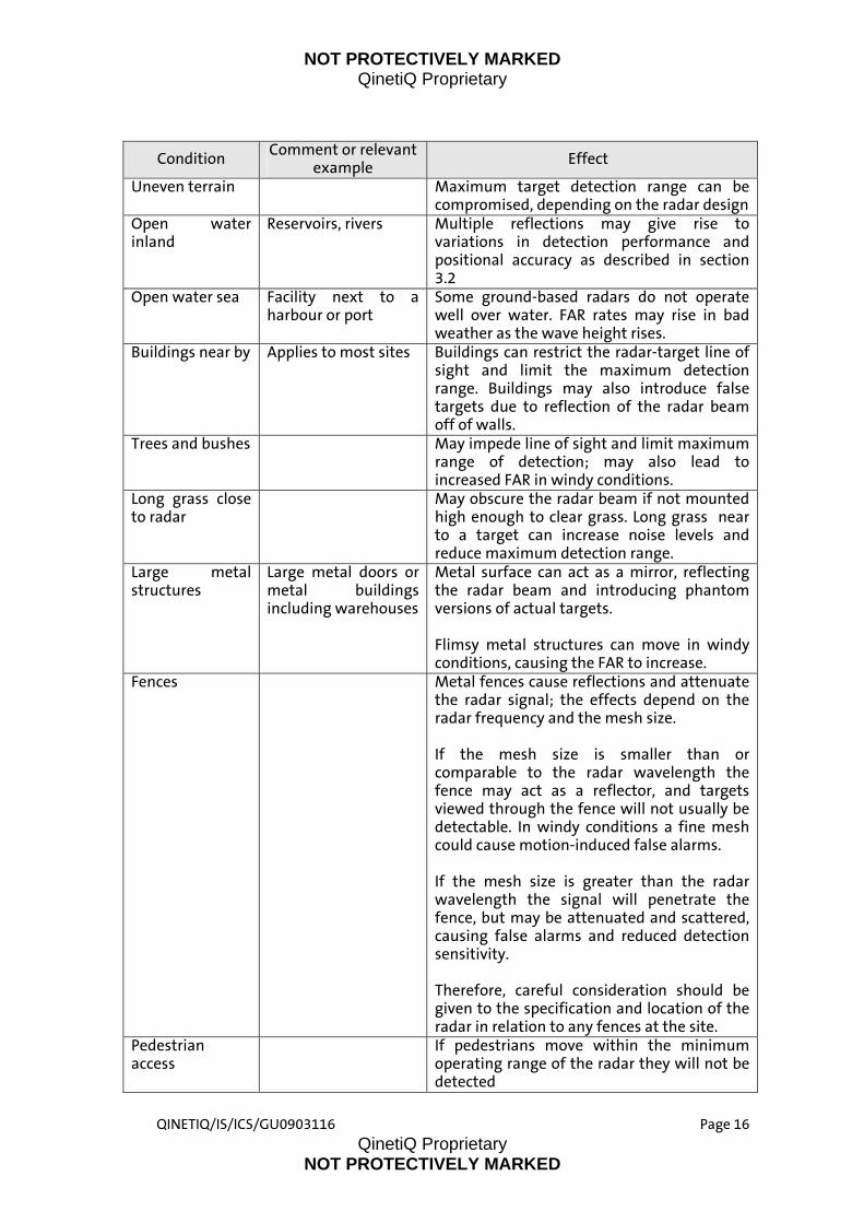
Table 2 discusses the environmental factors that affect the performance of a protective security radar and need to be taken into consideration when formulating the specification.
NOT PROTECTIVELY MARKED QinetiQ Proprietary
QINETIQ/IS/ICS/GU0903116 Page 16 QinetiQ Proprietary
NOT PROTECTIVELY MARKED
Condition Comment or relevant example Effect
Uneven terrain Maximum target detection range can be compromised, depending on the radar design
Open water inland
Reservoirs, rivers Multiple reflections may give rise to variations in detection performance and positional accuracy as described in section 3.2
Open water sea Facility next to a harbour or port
Some ground-based radars do not operate well over water. FAR rates may rise in bad weather as the wave height rises.
Buildings near by Applies to most sites Buildings can restrict the radar-target line of sight and limit the maximum detection range. Buildings may also introduce false targets due to reflection of the radar beam off of walls.
Trees and bushes May impede line of sight and limit maximum range of detection; may also lead to increased FAR in windy conditions.
Long grass close to radar
May obscure the radar beam if not mounted high enough to clear grass. Long grass near to a target can increase noise levels and reduce maximum detection range.
Large metal structures
Large metal doors or metal buildings including warehouses
Metal surface can act as a mirror, reflecting the radar beam and introducing phantom versions of actual targets.
Flimsy metal structures can move in windy conditions, causing the FAR to increase.
Fences Metal fences cause reflections and attenuate the radar signal; the effects depend on the radar frequency and the mesh size. If the mesh size is smaller than or comparable to the radar wavelength the fence may act as a reflector, and targets viewed through the fence will not usually be detectable. In windy conditions a fine mesh could cause motion-induced false alarms. If the mesh size is greater than the radar wavelength the signal will penetrate the fence, but may be attenuated and scattered, causing false alarms and reduced detection sensitivity. Therefore, careful consideration should be given to the specification and location of the radar in relation to any fences at the site.
Pedestrian access
If pedestrians move within the minimum operating range of the radar they will not be detected

NOT PROTECTIVELY MARKED QinetiQ Proprietary
QINETIQ/IS/ICS/GU0903116 Page 17 QinetiQ Proprietary
NOT PROTECTIVELY MARKED
Condition Comment or relevant example Effect
Vehicular access Vehicles close to the radar can cause signal overload in the radar sensor and lead to false alarms and inaccurate detections.
Wildlife- ground based
E.g. rabbits, foxes, deer, or dogs.
Can cause increase in FAR. Animals moving within the radar beam may be effectively indistinguishable from humans. Smaller animals (eg rabbits) present a smaller target to the radar than large animals (eg deer) and are less likely to produce false alarms, except at short range.
Wildlife – air based
E.g. flocks of birds (such as gulls and crows congregating near rubbish tips or starlings flying home to roost)
Can cause an increase in FAR if flying within the radar beam. A flock of birds can produce returns similar to those from a much larger moving target.
Table 2: Environmental conditions and their effect on radar performance
3.4 Performance Requirements- Detection
Detection performance depends on many factors including: the radar specification, target characteristics, attack types and attack styles, the nature of the terrain, and the presence of buildings or vegetation within the radar line of sight. Terrain undulation in particular can have a large effect on the performance of ground based surveillance radars. Probability of detection normally decreases with increasing range, but substantial additional variations in detection probability may be observed over undulating terrain because of partial or complete obscuration of the radar line of sight.
Different types of radar may perform better or worse depending on the direction of motion of the target. Hence it is important that the attack types and styles include examples of radial attacks, where the target travels directly towards the radar, and transverse attacks, where the target travels perpendicular to the radar line of sight.
The specification should define the (minimum) probability of detection required against all targets of interest within the detection zone.
If local terrain or buildings limit the line of sight, the installer may be unable to meet these requirements over the entire zone from one location, and may deploy a wide area surveillance radar and fill-in radars to provide the necessary coverage. (See, for example, Figure 2, which shows wide area and fill-in radars deployed at a power station.)
The radar tests should be designed to ensure that targets can be detected reliably throughout the detection zone against the full range of target types and attack styles.
At some sites it might be appropriate for the purchaser to specify a smaller detection zone for people than for vehicles. This would give the installer more freedom to offer an economic design.
Tests should be identified and implemented during the commissioning of the radar system to ensure the radar is functioning correctly (see section 4.2 for further details).

NOT PROTECTIVELY MARKED QinetiQ Proprietary
QINETIQ/IS/ICS/GU0903116 Page 18 QinetiQ Proprietary
NOT PROTECTIVELY MARKED
The most physically vulnerable parts of the radar are the radar antenna and receiver electronics and the cables connecting these units to the control station. Appropriate selection of radar type together with system design can provide a level of mitigation of this threat.
All radars are vulnerable to Electronic Countermeasures (ECM) (e.g. RF noise jamming) which can seriously degrade performance or completely deny availability. However this requires a certain degree of specialist knowledge/electronic equipment and at most sites is probably less likely to occur than physical attack. If the radar is subject to the most common form of jamming (wideband noise jamming) this should be evident to the operator as the noise levels on the display will increase dramatically.
If the system is being installed to counter a specific threat this needs to be defined at the specification stage.
3.5 Performance Requirements- False Alarms
The system false alarm rate must be minimised while maintaining the required detection performance. This is because at most sites all alarms would need to be assessed and responded to appropriately. A high FAR can lead to operator loss of confidence in the system and hence to genuine targets being missed.
The FAR can be controlled by adjusting the radar's sensitivity. Normally, a detection threshold is increased to decrease radar sensitivity and reduce the FAR. The FAR and probability of detection are therefore related.
In addition to the required detection rate, the specification should specify the acceptable false alarm rate, in terms of the number of false alarms per km2 per day. It is up to the site manager to determine an acceptable level for the false alarm rate at their site.
The FAR will not be constant, it can vary throughout the day and on a seasonal basis. When deciding the acceptable FAR the daily and seasonal variations in this parameter should be taken into consideration.
For this reason, when evaluating the radar system after commissioning, it is recommended that this is undertaken over a minimum 8 month period including the winter period, and that 10 per cent of the total system price be held back until completion of this extended period of evaluation.
The advice given above is only a guide. It is important that the purchaser makes appropriate considerations for their particular site and circumstances when specifying required detection and false alarm rates based on their operational requirements.

NOT PROTECTIVELY MARKED QinetiQ Proprietary
3.6 Performance Requirements- Availability
The specification should stipulate an expected level of reliability in terms of the acceptable down time. The specification should include provision of secondary systems or procedures if any periods of downtime are unacceptable.
3.7 Control and Indication
At the most basic level radars provide an interface called the Plan Position Indicator (PPI) which paints out the range and bearing of detections that appear as points on the display. In general these are designed for expert interpretation. See Figure 4 for a simple PPI display. A more tailored and appropriate interface will be required for security operators if the system is to be used efficiently. It is important to specify how the operator will interact with and respond to the system. This will affect the specification.
Figure 4: An example of a simple PPI display
QINETIQ/IS/ICS/GU0903116 Page 19 QinetiQ Proprietary
NOT PROTECTIVELY MARKED
NOT PROTECTIVELY MARKED QinetiQ Proprietary
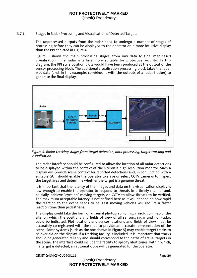
3.7.1 Stages in Radar Processing and Visualisation of Detected Targets
The unprocessed outputs from the radar need to undergo a number of stages of processing before they can be displayed to the operator on a more intuitive display than the PPI depicted in Figure 4.
Figure 5 shows the main processing stages, from raw data to final map-based visualisation, in a radar interface more suitable for protective security. In this diagram, the PPI style position plots would have been produced at the output of the sensor processing block. The additional visualisation processing block takes the radar plot data (and, in this example, combines it with the outputs of a radar tracker) to generate the final display.
Figure 5: Radar tracking stages from target detection, data processing, target tracking and visualisation
Figure 5
The radar interface should be configured to allow the location of all radar detections to be displayed within the context of the site on a high resolution monitor. Such a display will provide scene context for reported detections and, in conjunction with a suitable GUI, should enable the operator to slave or select CCTV cameras to inspect the target area and determine whether the target is a genuine threat.
It is important that the latency of the images and data on the visualisation display is low enough to enable the operator to respond to threats in a timely manner and, crucially, achieve "eyes on" moving targets via CCTV to allow threats to be verified. The maximum acceptable latency is not defined here as it will depend on how rapid the reaction to the event needs to be. Fast moving vehicles will require a faster reaction time than pedestrians.
The display could take the form of an aerial photograph or high resolution map of the site, on which the positions and fields of view of all sensors, radar and non-radar, could be indicated. Plot locations and sensor locations and fields of view must be accurately co-registered with the map to provide an accurate representation of the scene. Some systems (such as the one shown in ) may enable target tracks to be overlaid on the display. If a tracking facility is included, it is important that tracks should be generated reliably and should correspond to the paths of actual targets in the scene. The interface could include the facility to specify alert zones, within which, if a target is detected, an automatic cue will be generated for the operator.
QINETIQ/IS/ICS/GU0903116 Page 20 QinetiQ Proprietary
NOT PROTECTIVELY MARKED

NOT PROTECTIVELY MARKED QinetiQ Proprietary
Figure 6 is a larger view of a user-friendly visualisation display from a surveillance system incorporating radar. The radar in this example provides full 360 degree wide area surveillance, and a radar track on a pedestrian can be seen marked in yellow. The operator has directed a Pan-Tilt-Zoom (PTZ) camera (whose location is off the edge of this view, but whose field of view is shown in lime green) to inspect the target.
Figure 6: Example of an intuitive radar visualisation display for a ground movement site security radar
3.7.2 Staffing and Facilities
In the past radar has been a specialized technology that has required specialist technical operators to control the radar and interpret the output. However, protective security ground movement radars are much simpler and easier to use. Provided suitable visualisation software and displays are employed as described in section 3.7.1, and basic training in the use of the systems is provided, such radars can be operated efficiently by non-specialists.
The requirement specification should set out the staffing and control requirements, including:
who will be responsible for the system; who will act as system administrator; who will operate the system; who will maintain the system and what level of intervention is envisaged
(simple diagnostics or more?); procedures for investigating and responding to threats; details of existing security infrastructure within which the radar will be
integrated; operator training requirements.
QINETIQ/IS/ICS/GU0903116 Page 21 QinetiQ Proprietary
NOT PROTECTIVELY MARKED

NOT PROTECTIVELY MARKED QinetiQ Proprietary
QINETIQ/IS/ICS/GU0903116 Page 22 QinetiQ Proprietary
NOT PROTECTIVELY MARKED
3.7.3 Alarm Handling
It is likely that alarms will not be resolved automatically, but by a human operator, based on their interpretation of the available data. The procedures to be followed when investigating a potential threat, verifying it as genuine and generating and responding to an alarm should be included in the specification, with a clear timeline for each stage in the process, because they may have a direct effect on the timeliness and accuracy requirements for the radar data.
3.7.4 System Resilience
This may specify the requirements for operation in the event of a mains power failure. It will, for example, specify whether the system should shut down automatically on switching to a back up UPS power supply.
The reporting requirements in the event of system malfunction or breakdown should be included in the specification.
3.8 Documentation
As a minimum, an operator's manual will be required, describing the operation of the radar system and simple fault finding and diagnostics procedures. Depending on the operational requirements and the envisaged arrangements for system installation, maintenance and support the following may also be required.
a system installer's guide a system administrator's guide a system maintenance plan a system decommissioning plan
3.9 Selecting a System
The specification should give an indication of the process by which suppliers responses will be evaluated, including details of any factors that will be given particularly high weighting in the assessment (e.g. false alarm performance, system reliability or price), and, if applicable, details of any planned comparison tests between short-listed systems.

NOT PROTECTIVELY MARKED QinetiQ Proprietary
4 Installation This section discusses the procedures and requirements for installing and commissioning a typical site security ground movement radar. Section 4.1 discusses the installation procedure and the physical and environmental factors that need to be considered when carrying out an installation; while section 4.2 provides suggestions for commissioning tests.
4.1 General
The external physical and environmental factors that may influence the siting and installation of the radar system have been described in section 3.
The radar supplier/installer should provide recommendations for siting and mounting their equipment to achieve the desired coverage and performance.
The siting of the radar(s) will be governed by the need to achieve line of sight coverage throughout the specified zone. For an area surveillance system the detection zone will usually be a large open area, with relatively unobstructed sight lines. Area surveillance radars that do not provide 360 degree coverage can often be mounted on the side of a building, providing coverage to one side of the building. Fill in staring radars may generally be deployed in close proximity to buildings (for example to monitor areas between buildings outside the line of sight of an area surveillance radar), close to large stands of vegetation, or adjacent to fences.
The radar should be positioned at a height where all relevant targets can be illuminated by the radar beam. In this way optimum performance will be obtained.
illustrates the principle: if the antenna is mounted too low targets may be obscured by terrain, by elevating the antenna coverage is improved. However, this is a simplified representation, and other factors related to the radar design (particularly the width of the beam in elevation) will influence the mounting height.
Figure 7
Figure 7: The effect of radar mounting height and terrain on target visibility
QINETIQ/IS/ICS/GU0903116 Page 23 QinetiQ Proprietary
NOT PROTECTIVELY MARKED
NOT PROTECTIVELY MARKED QinetiQ Proprietary
QINETIQ/IS/ICS/GU0903116 Page 24 QinetiQ Proprietary
NOT PROTECTIVELY MARKED
The radar should be mounted securely according to the installer's recommendations on a pedestal, wall or pole, depending on the design. In exposed sites it is important that the antenna mounting does not flex or bend appreciably under wind loading, or location accuracy will suffer.
If there are any large radar-reflective objects within the field of view false targets may be generated and detection sensitivity may suffer. Generally speaking, large objects should not be positioned in the field of view very close to the radar (in the first few metres).
Grass in the vicinity of the antenna should be mowed, particularly if the antenna is to be mounted at low level.
The cabling for radar power supplies and feeds to the operator control and display unit should ideally be buried to provide physical protection and eliminate trip hazards.
Following the installation of the antenna and receiver electronics, and their connection to the power supply and the control and visualisation display unit, the radar antenna will need to be aligned/levelled on its mounting. This task will be undertaken by the installer.
The installer will be required to adjust the sensitivity of the radar to meet the specification without introducing unacceptable false alarms. To accommodate seasonal variations in the environment and to a lesser extent "drift" in the radar electronics, the radar sensitivity will need to be adjusted from time to time. This can be carried out as part of scheduled regular testing, using pedestrian and vehicle targets. Any variance from specified performance should be addressed by tuning of the system.
For information, in addition to practical detection tests on representative targets (i.e. people and vehicles) the installer may elect to carry out the initial alignment and coverage checks more accurately, by monitoring the signal strength from calibrated test targets placed at various points throughout the detection zone.
4.2 Commissioning
The radar manufacturer will usually provide a performance specification with the radar; typically, this will define its performance in terms of detection ranges on moving pedestrian and vehicular targets.
At this stage in the evolution of agreed performance standards a potential way forward would be to request that demonstrations of the radar at the site in question be undertaken prior to procurement. These demonstrations would provide confidence that the radar can provide a useful level of performance within the constraints of the site. It would be useful to include in the demonstrations both pedestrian and vehicular targets, and to conduct demonstrations under typical conditions prevailing at the site including general level of business and human activity, etc. The subsequent commissioning tests should reflect the threats described in the requirements specification in terms of the types of attacker and styles of attack.

NOT PROTECTIVELY MARKED QinetiQ Proprietary
QINETIQ/IS/ICS/GU0903116 Page 25 QinetiQ Proprietary
NOT PROTECTIVELY MARKED
5 System maintenance This section discusses regular checks and maintenance that should be undertaken to ensure that the radar system continues to perform at full capability.
5.1 System Audit
Normally, site security radars provide no automated performance monitoring and self diagnosis. This means that regular audits are required to verify that system performance has not degraded. It is recommended that these checks should include:
Occasionally (e.g. three monthly), repeat the commissioning tests against standard targets, to check that detection performance has been maintained;
Annual re-alignment of the radar antenna as described in section 4.1; Annually, repeat the full range of performance tests against the types of
attacker and styles of attack defined in the system specification.
5.2 Radar Maintenance
A radar system will generally have no user-serviceable parts; it will be serviced by the manufacturer or an authorized agent. It is suggested that basic scheduled maintenance of the radar should include:
Infrequent (e.g. annual) checks on the physical and electrical integrity of all exterior cabling;
Infrequent (e.g. annual) cleaning of the antenna radome (if fitted); Infrequent (e.g. annual) checks on the rigidity and security of the antenna
mounting;
5.3 Site Maintenance
Tall vegetation (bushes and trees) in the line of sight to the target will reduce detection sensitivity, and need to be sensibly maintained, particularly if they are close to the radar.
Tall grass can increase the noise background, particularly in windy conditions, and reduce detection sensitivity. It is recommended that the area around the radar antenna be kept mown, particularly if the antenna is mounted within 1 metre of the ground.
General debris in the area surrounding the antenna should be avoided or cleared on a regular basis. No objects or coverings should be left on the radar antenna.
If new buildings are being constructed within the detection zone or close to the zone perimeter the comments in section 3 regarding the potential for multiple reflections from buildings causing false targets should be taken into consideration. In severe cases, it may be preferable to reposition an area surveillance radar away from any large newly-introduced reflecting surfaces.

NOT PROTECTIVELY MARKED QinetiQ Proprietary
QINETIQ/IS/ICS/GU0903116 Page 26 QinetiQ Proprietary
NOT PROTECTIVELY MARKED
6 Reference/ Bibliography [1] Skolnik, M I, Radar Handbook, McGraw Hill Inc, 1990. [2] CPNI Guide to Producing Operational Requirements for Security Measures, April
2007. [3] HOSDB Publication 76/08, Ground Based Perimeter Intruder Detection System
(PIDS) Guidance Document, October 2008.
NOT PROTECTIVELY MARKED QinetiQ Proprietary
QINETIQ/IS/ICS/GU0903116 Page 27 QinetiQ Proprietary
NOT PROTECTIVELY MARKED
7 Glossary of Terms and Definitions In this document, the following terms and definitions apply.
7.1 Radar
Ra(dio) d(etection) a(nd) r(anging) (Radar).
7.2 Detection Zone
The area covered by the radar within which intruders should be detected.
7.3 True Alarm
A true alarm is a detection (radar plot) or sequence of detections caused by a human or vehicle entering or moving within the detection zone.
Typically the generation of an alarm will involve the interpretation of a display by an operator. In a perimeter coverage (barrier) system a single detection may be enough to raise an alarm whereas in an area surveillance radar an alert may be raised only if an apparently connected sequence of detections (also known as a track) is observed.
7.4 Detection Rate
A radar can be used to set up and monitor a physical barrier in the same way as a PIDS. With regard to barrier coverage, therefore, we can use the same definition of detection rate as used for PIDS:
- The detection rate for a particular attack style is the percentage of attacks (true alarms) successfully detected during the evaluation of that attack style.
- The overall detection rate is the average of the percentage detection rates calculated for each attack style in the evaluation.
In addition, radar provides area coverage, but there is no direct equivalent of the detection rate metric to represent area surveillance performance.
7.5 False Alarm
A false alarm is a detection (radar plot) not caused by a human or vehicle moving within the detection zone. In the specification of radar systems a false alarm generally refers to a single detection not generated by a valid threat target.
False alarms may be caused by reflections from the natural environment (such as wind blown grass, or foliage and branches on trees), man-made structures, or animals; or may have no obvious cause (produced by electrical noise in the receiving system).
7.6 False Alarm Rate
For protective security applications false alarm rate is defined as the mean rate at which false alarms are generated by the radar per unit area per unit time. False alarm rate is usually expressed in terms of the number of false alarms per km2 per day.

NOT PROTECTIVELY MARKED QinetiQ Proprietary
QINETIQ/IS/ICS/GU0903116 Page 28 QinetiQ Proprietary
NOT PROTECTIVELY MARKED
Note that radar engineers use a different definition of false alarm rate; they define it as the mean rate at which false alarms are generated by the radar, without reference to the area covered. Despite this difference in convention, any radar manufacturer or installer responding to the specification should be able to express the false alarm rate in the correct units.
7.7 Detection Range
For protective security applications detection range is defined as the range at which relevant targets such as pedestrians or vehicles can be detected by the radar with a specified probability of detection, at a specified false alarm rate. For example, the requirement might specify the range at which a pedestrian target with a nominal Radar Cross Section of 1m2 can be detected with probability 0.95 at a false alarm rate of 4 per km2 per day.
Note that radar engineers will be more familiar with a different definition of detection range: namely, the range at which a particular target can be detected with a specified probability at a specified probability of false alarm. The conversion between the two forms is straightforward.
7.8 Radar Cross Section
The radar cross section (RCS) is a measure of the equivalent "echoing area" of a target. The RCS determines how much of the radar power incident on a target is reflected back towards the radar. Radar cross section does not necessarily bear a simple relationship to the physical area of the target.
7.9 Other Acronyms Used
CSE Catalogue of Security Equipment
CCTV Closed Circuit Television
CPNI Centre for the Protection of National Infrastructure
FAR False Alarm Rate
OFCOM Office of Communications
PIDS Perimeter Intruder Detection System
RF Radio Frequency

NOT PROTECTIVELY MARKED QinetiQ Proprietary
QINETIQ/IS/ICS/GU0903116 Page 29 QinetiQ Proprietary
NOT PROTECTIVELY MARKED
Initial distribution list
External
CPNI - 3 Copies
QinetiQ
Project File
NOT PROTECTIVELY MARKED
NOT PROTECTIVELY MARKED
Q
Customer Contact TeamQinetiQCody Technology ParkIvely Road, FarnboroughHampshire GU14 0LXUnited KingdomTel: +44 (0)8700 100 942www.QinetiQ.com
© Copyright QinetiQ Group plcQINETIQ/IS/ICS/GU0903116
Q
TDF/21Central SupportPO Box 60628LondonSW1P 9HA


![Automated Driving: Design and Verify Perception Systems · Velocity: [-9.37 0 0] Size: [0 1.8 0] Radar-based object detector Radar Detector SensorID = 2; Timestamp = 1461634696407521;](https://static.documents.pub/doc/80x56/5f775a0d2f40265a11695144/automated-driving-design-and-verify-perception-systems-velocity-937-0-0-size.jpg)


