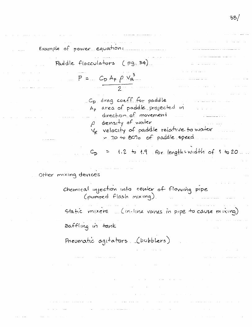
34
105
104
103
102
10-4 10-3 10-2 10-1 102 103 104 105 106
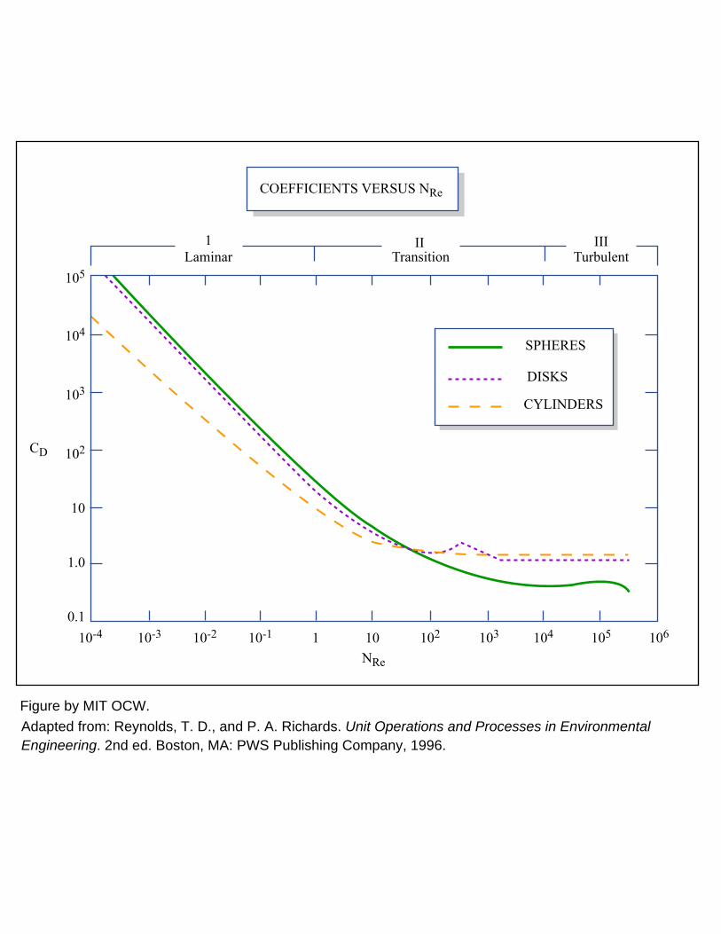
II III1
10
10
1.0
0.1 1
NRe
CD
SPHERES
DISKS
CYLINDERS
Re
Laminar
COEFFICIENTS VERSUS N
Transition Turbulent
Figure by MIT OCW. Adapted from: Reynolds, T. D., and P. A. Richards. Unit Operations and Processes in EnvironmentalEngineering. 2nd ed. Boston, MA: PWS Publishing Company, 1996.
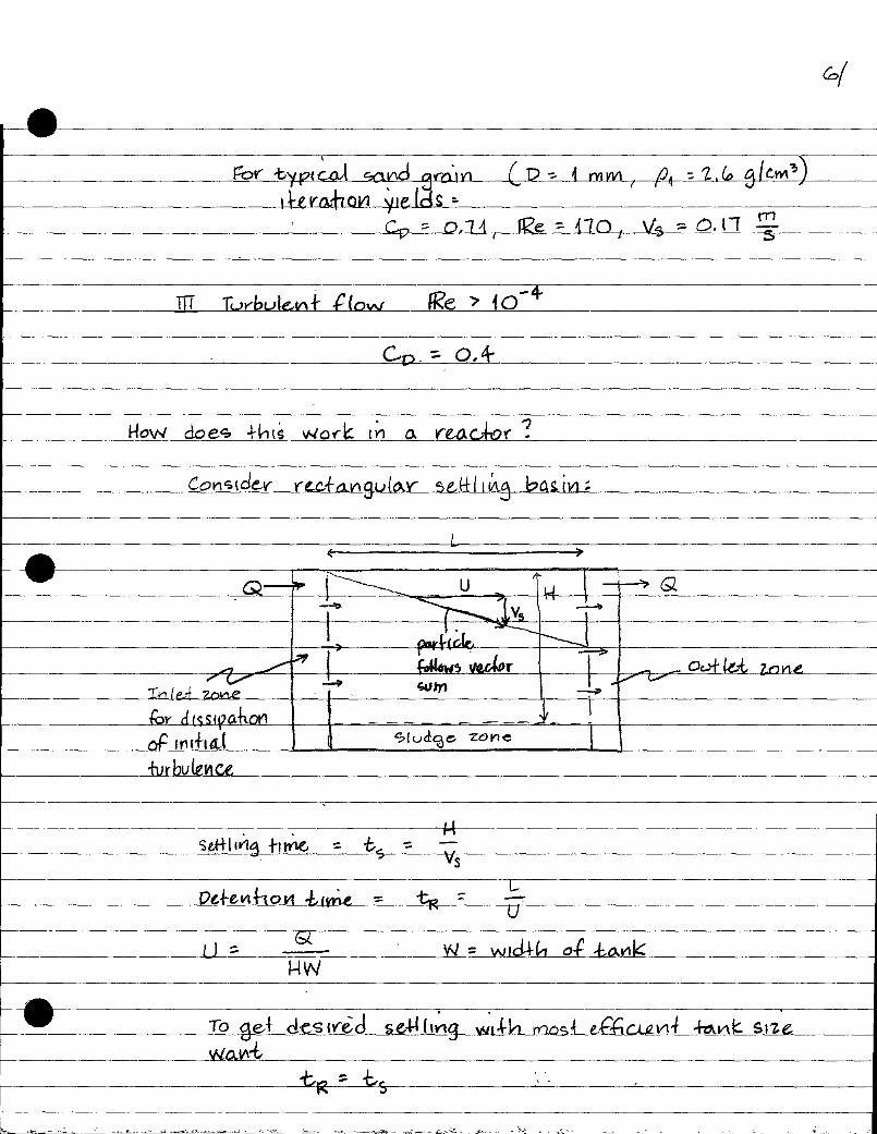

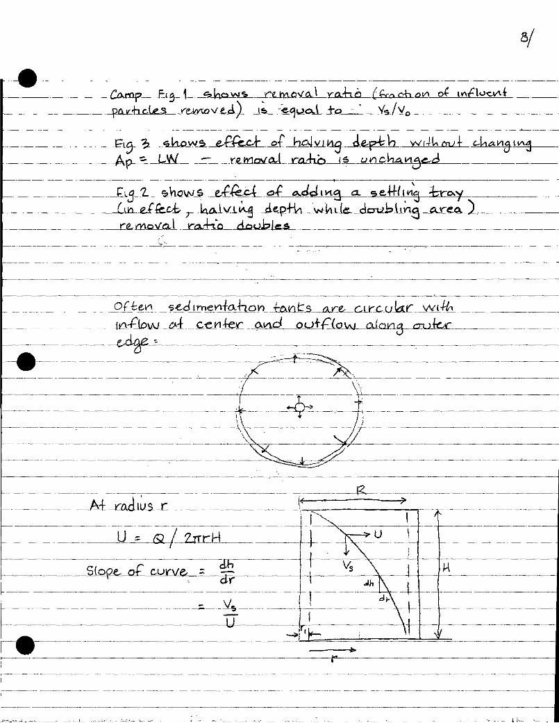

H
INLET
ZONE e
V v
vo
SETTLING ZONE
SLUDGE ZONE
OUTLET ZONE
V
Zones of a rectangular, horizontal, continuous-flow sedimentation basin.
2V
2V
Reduced tank depth does not increase removal ratio.
1/2 H v
vo
1/2 H
1/2 H
v 1/2 v0
Intermediate Tray
V
V
Tray in tank provides added floor area & increases solids removal
Figure by MIT OCW.
Adapted from: Camp, T. R. "Studies of Sedimentation Basin Design." Sewage and Industrial Wastes25, no. 1 (1953): 1-12.


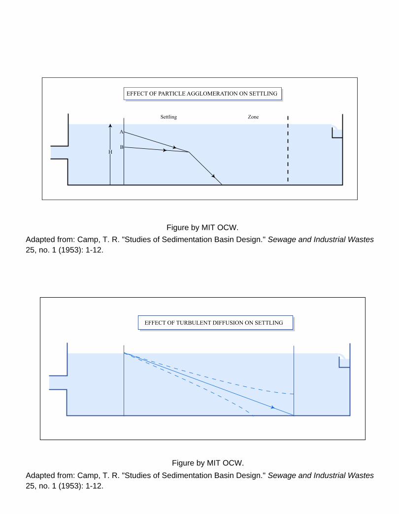
A
B H
Settling Zone
EFFECT OF PARTICLE AGGLOMERATION ON SETTLING
Figure by MIT OCW.
EFFECT OF TURBULENT DIFFUSION ON SETTLING
Figure by MIT OCW. Adapted from: Camp, T. R. "Studies of Sedimentation Basin Design." Sewage and Industrial Wastes25, no. 1 (1953): 1-12.
Adapted from: Camp, T. R. "Studies of Sedimentation Basin Design." Sewage and Industrial Wastes25, no. 1 (1953): 1-12.

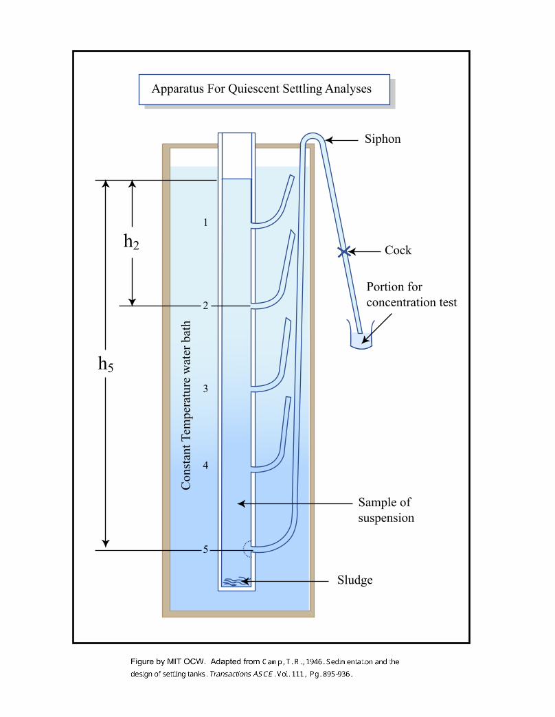
Siphon
Cock
Sample of suspension
Portion for concentration test Sam
ple of Suspension
Sludge
1
2
3
4
5
h5
h2
Con
stan
t Tem
pera
ture
wat
er b
ath
Apparatus For Quiescent Settling Analyses

�h1
�h2
�h3
�h4
h4
h3
t1 t2 t3 t4 t5
R5 R4 R3 R2
R1
h2
h1
h5
40% 50% 60% 70% 80%
TIME
DEP
TH
0.5 m
150 mm
Isopercent Removal Curves
Sampling Ports
Figure by MIT OCW.
Adapted from: G. Tchobanoglous, F. L. Burton, and H. D. Stensel. Wastewater Engineering:Treatment and Reuse. 4th ed. Metcalf & Eddy Inc., New York, NY: McGraw-Hill, 2003, p. 369.

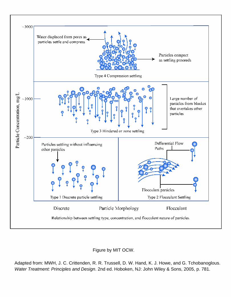
Figure by MIT OCW.
Adapted from: MWH, J. C. Crittenden, R. R. Trussell, D. W. Hand, K. J. Howe, and G. Tchobanoglous.Water Treatment: Principles and Design. 2nd ed. Hoboken, NJ: John Wiley & Sons, 2005, p. 781.


Sludge
Sludge Scum Scum Scum box
Chains
Chains
Skimmer
Skimmer
Scraper board
Scraper board
Influent
Sludge hoppers
Sludge hoppers
Drive motor
Drive
Influent
Sprockets
B
A
Longitudinal Section
Plan
WS
Drawoff
Drawoff
Effluent
Effluent
Effluent troughs
RECTANGULAR SETTLING TANK
Figure by MIT OCW. Adapted from: Reynolds, T. D., and P. A. Richards. Unit Operations and Processes in Environmental Engineering. 2nd ed. Boston, MA: PWS Publishing Company, 1996, p. 249. ISBN: 0534948847.

Clarifier
Corner blade
Corner blade
Guide plate
Chain
Influent channel
Influent pipe
channel
Blades
Counter weight
Drive Unit
Cage Blade Rake arm
Flocculator
Flash mixer Chamber
Paddle
Chain Dry well
Sprocket Gear motor
Sheaves
Sludge pocket
PLAN
Walk way
Effluent pipe
Effluent
Weir
Baffle
Stuffing box
Rake armConcrete pier
Handrail
Influent pipe
Flow
Cage
Flocculator & square sedimentation tank for water clarification, illustrating ceoss-flowoperation.
Top of tank Diffuser
Water level
Baffle
Sludge discharge pipe
Turntable
Figure by MIT OCW.Adapted from: Droste, R. L. Theory and Practice of Water and Wastewater Treatment.Hoboken, NJ: John Wiley & Sons, 1997.

Rotation
Flume
Flocculation Skirt
Bridge
Collection trough
orifaces
Settling zoneSettling zone
Inlet port
Flocculation zone
Mixer
Collection Trough
Scraper Arm
Effluent
Effluent flume with submerged
Water level
Flocculator-clarifier provides mixing, flocculation, & sedimentation in a compartmented concentric circular tank.
Figure by MIT OCW.Adapted from: Droste, R. L. Theory and Practice of Water and Wastewater Treatment. Hoboken, NJ: John Wiley & Sons, 1997.
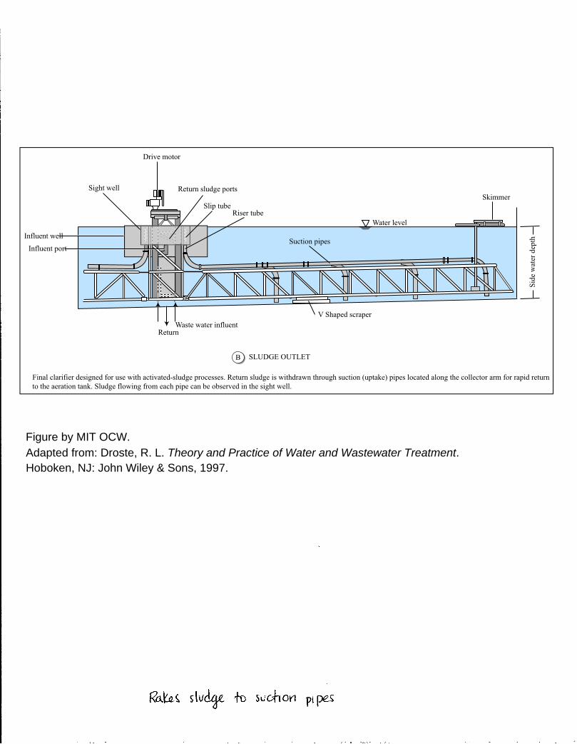
Figure by MIT OCW.Adapted from: Droste, R. L. Theory and Practice of Water and Wastewater Treatment.Hoboken, NJ: John Wiley & Sons, 1997.
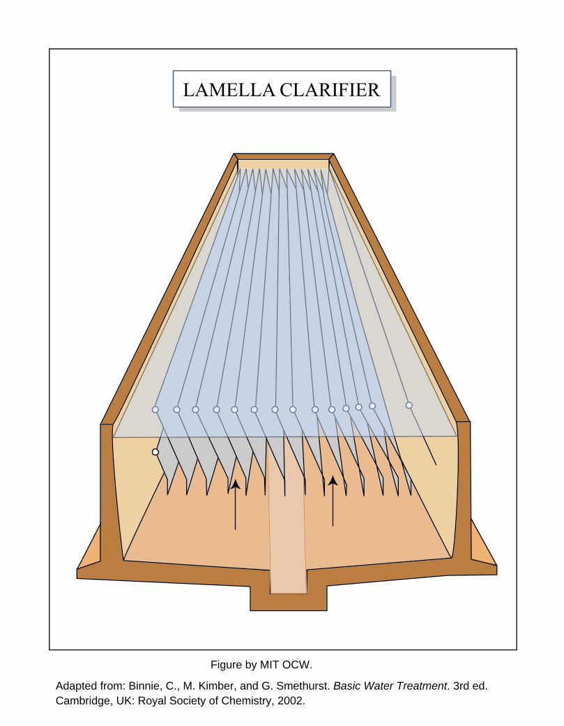
Figure by MIT OCW.
Adapted from: Binnie, C., M. Kimber, and G. Smethurst. Basic Water Treatment. 3rd ed.Cambridge, UK: Royal Society of Chemistry, 2002.