Seismic analysis and retrofit of a historic masonry building
C. C. Spyrakos1, P. Touliatos2, D. Patsilivas1, G. Pelekis1, A. Xampesis1 & Ch. A. Maniatakis1 1Department of Civil Engineering, National Technical University of Athens, Greece 2Department of Architectural Engineering, National Technical University of Athens, Greece
Abstract
This study presents the seismic analysis of a three-storey unreinforced masonry building that was heavily damaged during the Aigion 1995 earthquake. The building is located a few kilometers from the fault, thus subjected to “near field” ground motions. Seismic analysis of the building, using an elaborate finite element model with properties extracted from material testing of representative structural members and excitation from records obtained from a nearby station, revealed the mechanism of partial failure of the top floor as well as the weaknesses of the original building design and construction. Alternative retrofit and strengthening techniques that can be implemented while maintaining the architectural and aesthetical appearance of the historic building are presented. Keywords: seismic analysis, retrofit of masonry building, near-field seismic motion.
1 Introduction
The city of Aegio has suffered several strong earthquakes through the years. The most recent powerful earthquake which caused human losses occurred on June 15, 1995. It was a 6.4 Ms shallow depth earthquake with an epicentral distance of about 18 km southwest of Aegio that caused the death of 26 people, massive, and in many cases, irreparable damages to both modern and older (masonry) buildings [1]. In 1997 a weaker earthquake caused additional damage on already deteriorated buildings.
The three story Panagiotopoulos’ mansion is located at the city centre of Aegio (fig. 1). It has a basement of similar dimensions with the other floors. Its plan is rectangular with dimensions 18.68 m by 14.65 m and height of floors of about 4.5 m. The timber roof is rectangular with a Byzantine tile coating. The arrangement of openings on the front views of the building is well proportioned to a vertical axis, and the same on the first and second floor. The external walls are made of sack masonry with thickness that is reduced with height. They are about 95cm thick at the ground floor and 86cm thick at the second floor. The internal walls are 80cm thick at the ground floor, 75cm at the first and 68cm at the second floor. The walls are three-layered with exterior sides constructed with large boulder (stones) connected with mortar and smaller stones with thicker mortar placed between them. In the whole building, there are quite a few closets incorporated in the masonry walls that reach the height of interior openings. The openings of the external walls are formed at the upper part with shallow arches made of bricks. About 18% of the external walls are openings to the northern, southern and eastern view. To the western view, about 10% are openings. In the interior of the building there are two walls made of stone masonry. They are parallel to the narrow sides of the building and continue all the way to the roof. Communication among the floors is made through marble stairwell at the southern side of the building, which is supported by stonework, arches and horizontal beams. The light internal partition walls on the first and second floor of the building are made of bricks with a thickness of 17cm to 18cm supported on either powerful masonry walls or wooden floor beams. At various heights, along each of the interior walls there are two iron flat-shaped steel bars at about 3cm distance between them that augment and increase the bending and shear stiffness of the walls. The first and second story floors are made of timber. The floors of the ground floor are either timber or stone masonry domes located at the central part of the building where the wall openings of the basement are relatively small. It should be noted that the arrangement of the planks on the first and second floor is made in such a way that the orientation of wooden beams distributes the weight of the floors evenly along all the load carrying walls, so in case of an earthquake, the inertia forces are shared by all vertical walls. At the ground floor steel or timber bars of rectangular profile are anchored with metal plates to the transverse walls, in order to avert detachment of the interior walls at the corners (fig. 2). At the level of the roof base along the stonework there is also a crossbeam perimetrically to the interior side of the external masonry walls of the building. The cross-beam is attached to the stonework through metal sheets placed at about 1.5–2 m. The cross-beam plays a significant role in the static and seismic performance of the building since it: i) distributes the concentrated loads of the roof to the stone work averting local cracks due to compression; ii) contributes to the development of rigid diaphragm behavior at the floor levels and iii) functions as a fastening of the stonework augmenting the “integral” behavior of the building for seismic loads.
The building structural system is called a system of “poles on pillars” and presents two primary advantages: i) a multiple potential to redistribute the loads when some of its component fails and ii) it develops similar behavior along its two principal axes [2].
Figure 3: Damage distribution from on-site inspection.
2 Description of damages
The present condition of the building is disappointing because of the extent of the damages caused by the 1995 and 1997 earthquakes. What has played an important role to the damages is, on the one hand, the insufficient maintenance
prior to the earthquakes and on the other, not taking any necessary protection measures after the 1995 earthquake. Fig. 1 shows a large part of the external wall on the second floor that has collapsed during the 1995 earthquake. The southwestern corner of the building on the second floor has also collapsed. A qualitative interpretation of the representative damages shown in fig. 3 is presented below:
A. A crack of parabolic form over a window opening caused by inadequate bending strength. After the collapse of the southern external wall, the rest of the stone masonry carries even higher compressive loads.
B. “Shear” cracks forming an “X” caused by the alternating direction of seismic action. The inclination and form of the cracks depends on the vertical compressive loads carried by the walls, the position and size of the openings [3].
C. Cracks round the openings developed by the seismic forces parallel to the wall.
D. A crack located at the level of the arch at the ground floor. The crack is caused by either horizontal thrust acting on the masonry wall resulting in bending stresses and the co-existence of the intense shear stresses in this area.
E. Vertical cracks in the panels between windows caused by intense compression.
F. Diagonal crack in a wall with reduced thickness to form the chimney. G. Cracks caused by insufficient connection (lack of a cross beam) of the
floor beams at the first and second floor. H. Vertical cracks at the top of the intersections of transverse walls. There is
a tendency of separation between the walls which denotes insufficient strength at their intersections.
2.1 Analysis for seismic loads and correlation with observed damages
The building walls were modeled and analyzed using finite elements [4]. Linear elastic behavior was assumed using three and four node thick shell elements, a process usually adopted for the analysis of similar structural systems, e.g. [3, 5]. Beam elements were used to model the timber parts, such as the floors. The response spectrum analysis that was carried out included a sufficient number of modes, as specified by the Code [6]. Fig. 4 shows the 8th mode of the building with T = 0.17 s which is the first most significant mode along the Χ direction with the largest participation factor (–39.65) and modal mass (62.82%). The 9th mode is the first most significant mode along the Υ direction with a participation factor of 31.02 and modal mass of 38.46%. The 9th mode exhibits an intense out of plane bending deformation of the flexible partition walls. It should be noted that the most significant modes in each direction are translational with out-of-plane bending of the exterior walls combined with deformation of the interior walls to maintain compatibility [7]. The inplane deformations of the walls corresponding to the first nine modes are insignificant. The second most significant mode is the 10th mode in the Y direction and exhibits in plane deformations of opposite side walls. The
transverse internal walls and especially the most flexible partitions follow the response of the external walls forced by displacement compatibility at their intersections resulting in bending deformations.
Figure 4: 8th mode shape.
The building was subjected to the response spectra of the Aegio 1975 earthquake, figs. 5 and 6. It must be emphasized that due to the orientation of the building along the direction of the coastline (which is also the direction of the earthquake fault); the spectra were applied along the X direction of the building, whereas the transverse spectrum was applied along the Y direction. This selection was based on the fact that the X direction of the building is parallel to the coastline. The spectra correspond to horizontal ground acceleration recorded a few kilometres from the mansion. The near-field ground motions are characterized by pulses with a maximum acceleration of 0.54g, a long period of about 0.5 s along the transverse direction to the fault and velocity of about 52 cm/s [8]. Masonry structures, such as the Panagiotopoulos building in Aegio have a small out of plane bending stiffness. The Aegio earthquake caused mostly bending out of level response and, as a result, tension prevailed over the construction with detrimental effects. The dynamic analysis showed that the building response was primarily affected by the translational modes along the X and Y-axes and that for the largest part of the building seismic demand surpassed the strength of the masonry.
Figure 5: Spectral acceleration in the Y direction.
Figure 6: Spectral acceleration in the X direction.
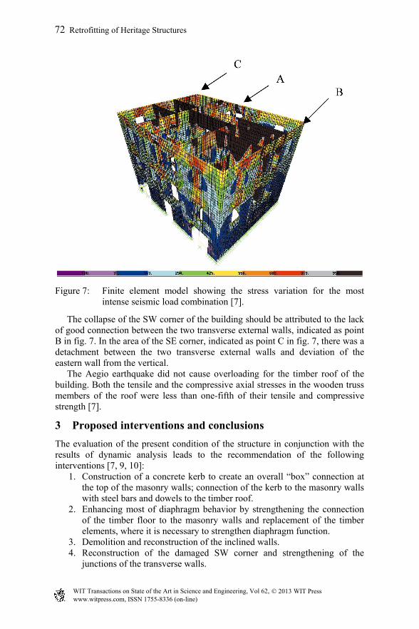
Use of a linear elastic model does not allow redistribution of stresses once a part of the structure has failed. However, use of this model demonstrates with remarkable accuracy the building parts that were either the first to fail or suffered considerable damage. In the area of the staircase at the 2nd floor level, indicated with (A) in fig. 7, the largest tensile stresses develop; this implies that this area is one of the first to fail during the earthquake. Out of plane failure is also favored with the internal partition walls. Moreover, after the collapse of the upper part of the wall in the stairwell, an increase of the tensiles stresses on the adjoining masonry is anticipated resulting in its collapse at a second phase, a fact demonstrated by the collapsed area in the southern view of the building shown in fig. 1 [7].
Figure 7: Finite element model showing the stress variation for the most intense seismic load combination [7].
The collapse of the SW corner of the building should be attributed to the lack of good connection between the two transverse external walls, indicated as point B in fig. 7. In the area of the SE corner, indicated as point C in fig. 7, there was a detachment between the two transverse external walls and deviation of the eastern wall from the vertical. The Aegio earthquake did not cause overloading for the timber roof of the building. Both the tensile and the compressive axial stresses in the wooden truss members of the roof were less than one-fifth of their tensile and compressive strength [7].
3 Proposed interventions and conclusions
The evaluation of the present condition of the structure in conjunction with the results of dynamic analysis leads to the recommendation of the following interventions [7, 9, 10]:
1. Construction of a concrete kerb to create an overall “box” connection at the top of the masonry walls; connection of the kerb to the masonry walls with steel bars and dowels to the timber roof.
2. Enhancing most of diaphragm behavior by strengthening the connection of the timber floor to the masonry walls and replacement of the timber elements, where it is necessary to strengthen diaphragm function.
3. Demolition and reconstruction of the inclined walls. 4. Reconstruction of the damaged SW corner and strengthening of the
5. Reconstruction of the collapsed area and strengthening of the masonry walls at the stairwell.
6. Repair and homogenization of the stonework mass. 7. Strengthening of the reduced mass of the stonework in the areas of
fireplaces. 8. Repair and strengthening of the stairwell. 9. Reconstruction of the roof by reusing old intact materials. 10. Use of pre-stressed tie-bars to connect intersecting walls.
A detailed discussion and presentation of an extensive repair and strengthening scheme is presented in [7]. A thorough evaluation of alternative schemes and corresponding dynamic analysis of the building showed that the construction of a concrete kerb at the roof level combined with enhancement of diaphragm action could lead to a system capable to suffer minor damages even to the Aegio near-field ground motion.
References
[1] Papazachos, B. & Papazachou, C., The earthquakes in Greece, Ziti Editions: Thessaloniki, 1997.
[2] Touliatos, P., Seismic behavior of traditional and historic buildings in Greece, Report to O.A.S.P., 2001.
[3] Groci, G., The Conservation and Structural Restoration of Architectural Heritage, Advances in Architectural Series, Computational Mechanics Publications: Southampton, UK, 1998.
[4] Spyrakos, C.C., Finite Element Modeling in Engineering Practice, Algor Publishing Division: Pittsburgh, P.A., 1995.
[5] Karantoni, F.V. & Fardir, M.N., Computed vs. observed seismic response and damage of masonry buildings. Journal of Structures Engineering ASCE, 118(7), pp. 1804-1821, 1992.
[7] Patsalivas, D., Pelekis, G. & Hambesis, A., Structural Renovation of the Panagiotopoulos Building in Aegion, Diploma thesis, N.T.U.A, 2004 (in Greek).
[8] Spyrakos, C.C., Maniatakis, C. A. & Taflabas, J., Critical evaluation of near field seismic records in Greece. ERES V, eds. C. A. Brebbia, D. E. Beskos, G. D. Manolis & C. C. Spyrakos, pp. 53-62, 2005.
[9] Tomazevic, M., Earthquake Resistant Design of Masonry Buildings, Imperial College Press: London 2001.
[10] Spyrakos, C.C., Strengthening of Structures for Seismic Loads, T.E.E., Athens, Greece, 2004 (in Greek).


![Retrofit Historical Masonry Walls with GFRP under Seismic Loading · 2015. 6. 11. · historic masonry building in seismic areas [7,8]. In the study of Catherin et al .[9] , an application](https://static.documents.pub/doc/80x56/6116ea99965243058f072b2d/retrofit-historical-masonry-walls-with-gfrp-under-seismic-loading-2015-6-11.jpg)


