63
Seismic Imaging of Karst: Work In Progress Dr Rod Eddies December 2013

Seismic Imaging of Karst:
Work In Progress
Dr Rod Eddies
December 2013

Synopsis
• subsurface risk
• geophysical methods and karst
• anatomy of a wavefield and seismic deliverables
• 3C seismic – recording the complete wavefield

after Gilbert, 2013
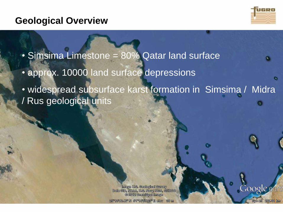
Geological Overview
• Simsima Limestone = 80% Qatar land surface
• approx. 10000 land surface depressions
• widespread subsurface karst formation in Simsima / Midra
/ Rus geological units

Why manage risk?
Source: Clayton 2001
*

Impact of Site Investigation On Overrun

Intrusive Investigations
• derive key ground data
geological
geotechnical
hydrogeological
• are spatially representative?
• are optimally planned both in number, distribution and depth?

Geophysical Investigations
• derive key ground data
geological
geotechnical
hydrogeological
• are well understood (benefits/limitations)?
• are appropriately deployed (best practice)?
• are optimally scheduled to help manage risk and reduce cost?

Capturing Experience
Geophysics

• subsurface risk
• geophysical methods and karst
• anatomy of a wavefield and seismic deliverables
• 3C seismic – recording the complete wavefield

Why Geophysics?
• relatively rapid screening for lateral and vertical variation
• effective targeting of intrusive programmes
• interpolation between controls
• appropriate phasing
• appropriate techniques
• appropriate execution

Electrical Resistivity Tomography (Europe – Karst)

Electrical Resistivity Tomography (Doha – Karst)

Ground Penetrating Radar (Europe - Karst)

Ground Penetrating Radar (Oman-Karst)
Data Example

Ground Penetrating Radar (Doha)

Limiting Factors For Investigation
• MASW – dependent on frequency content/site conditions
• Refraction – velocity inversion below Simsima Lst
• Microgravity – depth/resolution
• ERT – masking due to saline conditions
• GPR – conductivity/saline ground conditions
• EM – depth/resolution
Off the shelf geophysical solutions may face significant
limitations due to Qatar-specific site conditions

• subsurface risk
• geophysical methods and karst
• anatomy of a wavefield and seismic deliverables
• 3C seismic – recording the complete wavefield

Field Configuration - Schematic
Receivers Seismic Source

Anatomy of a Wavefield
Distance from source

Anatomy of a Wavefield
Distance from source
Tim
e fro
m s
ou
rce e
xcita
tion
Time-offset domain

Anatomy of a Wavefield
refracted waves
reflected waves
surface waves
Distance from source
Tim
e fro
m s
ou
rce e
xcita
tion

Seismic Deliverables: refraction
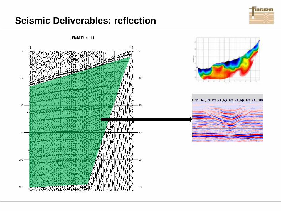
Seismic Deliverables: reflection

Seismic Deliverables: surface wave

Seismic Deliverables
P-wave velocity
distribution, layering,
discontinuities
Seismic stratigraphy,
discontinuities
S-wave velocity
distribution, Gmax,
layering,
discontinuities

MASW

Seismic Reflection

Seismic Reflection

Under what conditions does seismic work best?
Low noise* 8/10
Good surface coupling 9/10
Low velocity 9/10
Modest contrasts 8/10
*see next slide
Saturated materials 8/10
These
examples Qatar
1/10 to 3/10
2/10 to 5/10
2/10 to 8/10
2/10 to 8/10
2/10 to 5/10

Qatar Site Conditions

• subsurface risk
• geophysical methods and karst
• anatomy of a wavefield and seismic deliverables
• 3C seismic – recording the complete wavefield

Model Void
(Sloan et al 2010) Calculate V and H response

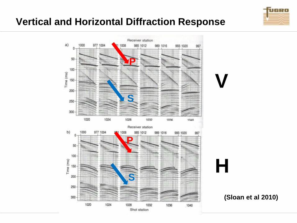
Vertical and Horizontal Diffraction Response
(Sloan et al 2010)
P
S
S
P
V
H
Vertical and Horizontal Diffraction Response
(Sloan et al 2010)
P
S
S
P
V
H

Actual Voiding – V Response
(Sloan et al 2010)
P P P

(Sloan et al 2010)
Resonance

Resonant Seismic Emission
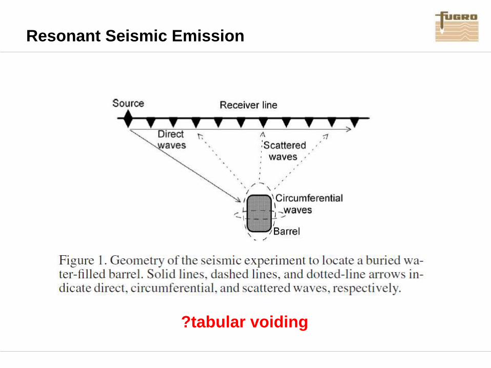
Resonant Seismic Emission
?tabular voiding

Resonant Seismic Emission

Resonant Seismic Emission

Objective diagnostics for voiding / filled cavities
1) Diffractions
• V and H geometry
• V and H velocity behaviour
• V and H polarity behaviour
• consistent shot-to-shot response
• consistent line-to-line response
2) Resonance
• monochromatic response
Important to capture the 3C wavefield

3C Land Streamer - Captured Wave Modes
• 500 - 1 km / day
• suitable for urban use

3C seismic (single) shot record
Vertical Cross-Line In-Line

Whole Record Spectrum
Input
Spectrum

V Response

H Response

Spectrum: H Response
Resonance?

V Response

Resonance?
Spectrum: V Response

H Response

Spectrum: H Response
Resonance?

Spectrum: Full Wavefield
Input
Spectrum

Spectrum: hi-pass filtered
Input
Spectrum

3C Full Wavefield Recording – no filters

3C Full Wavefield Recording – hi pass filtered

Hyperbolic/Reverse Move-Out Events

Hyperbolic/Reverse Move-Out Events

Hyperbolic/Reverse Move-Out Events
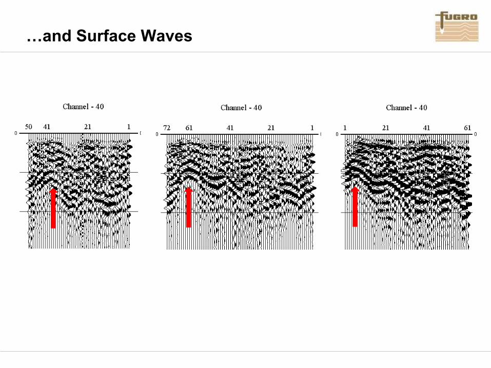
…and Surface Waves
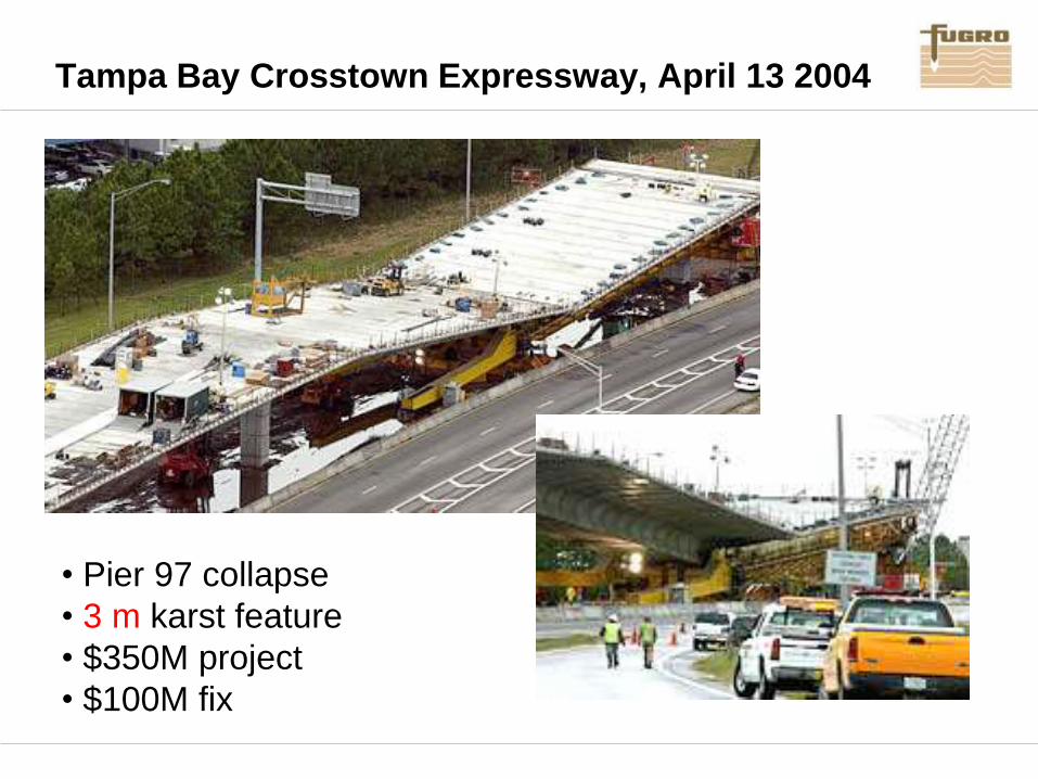
Tampa Bay Crosstown Expressway, April 13 2004
• Pier 97 collapse
• 3 m karst feature
• $350M project
• $100M fix

Possible Investigation Strategy for Qatar
1. Be aware of Qatar-specific limitations of geophysics
2. Optimise MASW methods
3. Acquire the multicomponent seismic wavefield
4. Derive 3C reflection response
5. Derive 3C diffraction response
6. Use well understood diagnostics
7. Interpret for voids/zone of discontinuities
8. Early days – control through BH is a must!

Thank You


