Fracture Mechanics of Concrete Structures Proceedings FRAMCOS-3 AEDIFICATIO Publishers, D-79104 Freiburg, Germany SEISMIC RETROFITTING TECHNIQUE USING CARBON FIBERS FOR REINFORCED CONCRETE BUILDINGS H. Katsumata, K. Kimura, and Y. Kobatake, Technical Research Institute, Obayashi Corporation, JAPAN Abstract New retrofitting techniques using carbon fibers are presented. For existing reinforced concrete columns, a CFRP winding technique is employed, in which carbon fiber strands or sheets are wound onto the surface of columns, impregnating and curing epoxy resin. The additional CFRP hoops are constructed to make the columns more ductile. However, debonding of CFRP from a concrete surface limits applications of these CFRP techniques for other retrofit works. From experimental and analytical research, debonding strength and effective bond length are found. Key words: CFRP, seismic retrofitting, reinforced concrete, jacketing, debonding, 1 Introduction After the 1995 Kobe Earthquake, national and local governments and engineer's societies have emphasized the importance of seismic retrofitting. However, since the current retrofit techniques require much inconvenience 1727
Transcript
Fracture Mechanics of Concrete Structures Proceedings FRAMCOS-3 AEDIFICA TIO Publishers, D-79104 Freiburg, Germany
SEISMIC RETROFITTING TECHNIQUE USING CARBON FIBERS FOR REINFORCED CONCRETE BUILDINGS
H. Katsumata, K. Kimura, and Y. Kobatake, Technical Research Institute, Obayashi Corporation, JAPAN
Abstract New retrofitting techniques using carbon fibers are presented. For
existing reinforced concrete columns, a CFRP winding technique is employed, in which carbon fiber strands or sheets are wound onto the surface of columns, impregnating and curing epoxy resin. The additional CFRP hoops are constructed to make the columns more ductile.
However, debonding of CFRP from a concrete surface limits applications of these CFRP techniques for other retrofit works. From experimental and analytical research, debonding strength and effective bond length are found. Key words: CFRP, seismic retrofitting, reinforced concrete, jacketing, de bonding,
1 Introduction
After the 1995 Kobe Earthquake, national and local governments and engineer's societies have emphasized the importance of seismic retrofitting. However, since the current retrofit techniques require much inconvenience
1727
to owners or users of buildings, a few retrofit works have been done yet. Today, CFRP (Carbon Fiber Reinforced Plastics) techniques are focused on because these techniques save the retrofitting cost and time and gain sufficient structural performance.
This paper describes an outline of the CFRP techniques and points out debonding of CFRP from concrete. The debonding of CFRP should be solved to enlarge the application field of the CFRP techniques. ·
2 of seismic retrofit techniques using CFRP
Material properties of carbon fibers Carbon fibers are very fine fibers with a diameter of 7µm and have
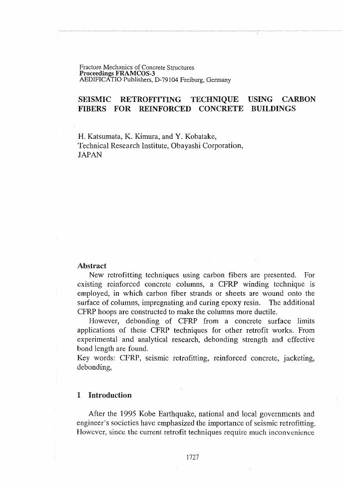
excellent properties for structural members, for example, high strength, high elastic modulas, light weight, and high durability. However, carbon fibers are very brittle as shown in Fig. 1, and very expensive, compared with steel. Thus, some consideration is needed to overcome these weak points.
A carbon fiber strand that consists of 12000 filaments of carbon fiber, or a carbon fiber sheet that consists of carbon fiber strands arranged in a same direction is a practical unit for actual applications. The carbon fiber filaments are loaded independently, which causes stress concentration to a
filaments. Since carbon fibers are· brittle, the filaments with the concentrated stress easily fracture before the stress begin to be shared with any other filaments. Therefore, impregnation of epoxy resin to carbon fibers is usually carried out to produce CFRP. The impregnated resin integrates the carbon fiber filaments in CFRP and reduces the stress concentration. On the other hand, the resin causes loss of durability and
'@' 3.0 0...
~ ~ 2.0 Q) lo-
w 1.0
0.0
Carbon Fiber
Aramid Fiber
2.0 4.0
Strain (%)
Fig. 1 Stress strain relationship of carbon fiber
1728
fire proof capacity. However, since buildings usually need finishings on the retrofitted members from architectural reasons, these problems are solved. The finishings cut ultra- violet rays that reduce durability of epoxy resin. The finishings that have the function of protecting covers can be heat insulation during a fire.
CFRP is strong but brittle, just like as a carbon fiber itself. Therefore, CFRP cannot be employed for a energy absorbing material that is very
· important in the current earthquake resistant design of buildings. For reinforced concrete structures, CFRP cannot be used for longitudinal bars at plastic hinge regions where the longitudinal bars play a role of energy absorbing devices. However, CFRP can be employed for transverse reinforcement to which plastic deformation is not required, and for the longitudinal reinforcement in the region where large plastic deformation is not expected ..
The last large problem with use of carbon fibers is the high price of carbon fibers. In case of newly constructing, carbon fibers is inferior to concrete and steel because in that case, the material cost occupies some percentage which is cannot be ignored. However, in the retrofit works, carbon fibers is not inferior because the material cost has a low percentage and the labor costs occupies a high percentage. If carbon fibers save the labor cost due to its light weight and flexibility, then carbon fibers may be widely spread. Actually speaking, this is the reason that CFRP retrofit techniques are often employed in Japan.
2.2 Behavior of retrofitted members In many cases in Japan, a CFRP technique of shear reinforcement is
employed for columns because such old columns have poor transverse reinforcement and cause the fatal collapse of a whole building, as was observed in Kobe. Onto the concrete surface of existing reinforced concrete columns, carbon fibers are wound, impregnating and curing epoxy resin. After curing, these CFRP additional hoops improve shear strength and ductility of the columns. There are two methods for this retrofit; one is a strand method using machine for winding carbon fiber strands, and the other is a sheet method employing by hand-lay-up of carbon fiber sheets. From the test results, the both methods are considered to have almost same structural performance .
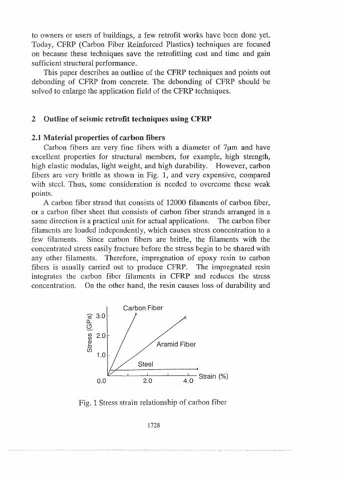
Fig. 2 shows the load displacement relationship of retrofitted and unretrofitted columns (Katsumata et. al, 1996). For the retrofitted column, the strand winding method was employed. The unretrofitted column failed in shear and showed brittle behavior. On the other hand, the retrofitted column failed in flexure and showed very ductile behavior. Most of
1729
-50
z 500 ::::;, "'O co 0
_J
-500
50 100 150 -50
Displacement (mm)
(a) Unretrofitted
z 500 ::::;,
-500
50 100 150
Displacement (mm)
(b) Retrofitted
Fig. 2 Behavior of CFRP retrofitted column
Displacement (mm) ~~~~----'~-'-~--'-~L...--l-~~
0 5 10 15 20
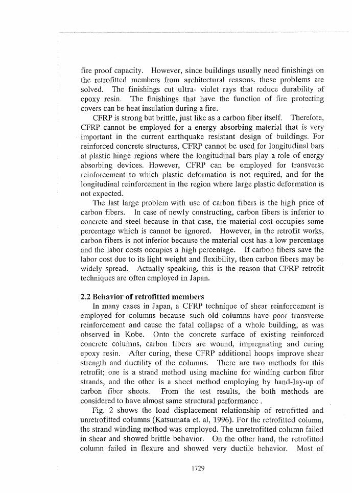
Fig. 3 Behavior of CFRP retrofitted circular hollow RC members
CFRP of this heavily retrofitted column did not fracture. For slightly retrofitted columns, flexural yielding was often observed, however, the wound CFRP fractured at the deformation determined by the provided CFRP quantity and the columns simultaneously lost lateral bearing capacity. This means that an adequate amount of CFRP should be provided for retrofitting. From many test results, a design procedure of the CFRP winding technique for columns was already established, including evaluation of both shear strength and ductility of retrofitted columns. This design procedure was approved by national highest authorities and applied for actual retrofit projects.
To improve bending capacity of reinforced concrete members, CFRP is glued on a concrete surface in the longitudinal direction. Fig. 3 shows the load displacement relationship of hollow circular reinforced concrete
1730
beams constructed as a model of existing reinforced concrete chimneys (Kimura et. al 1988 and Kobatake et. al 1993). Compared with the unretrofitted specimen, the retrofitted specimens showed large bearing capacity due to the glued CFRP. The capacity of the heavily retrofitted specimen was larger than that of the slightly retrofitted one. For this strengthening of bending capacity, a design procedure was also established and approved.
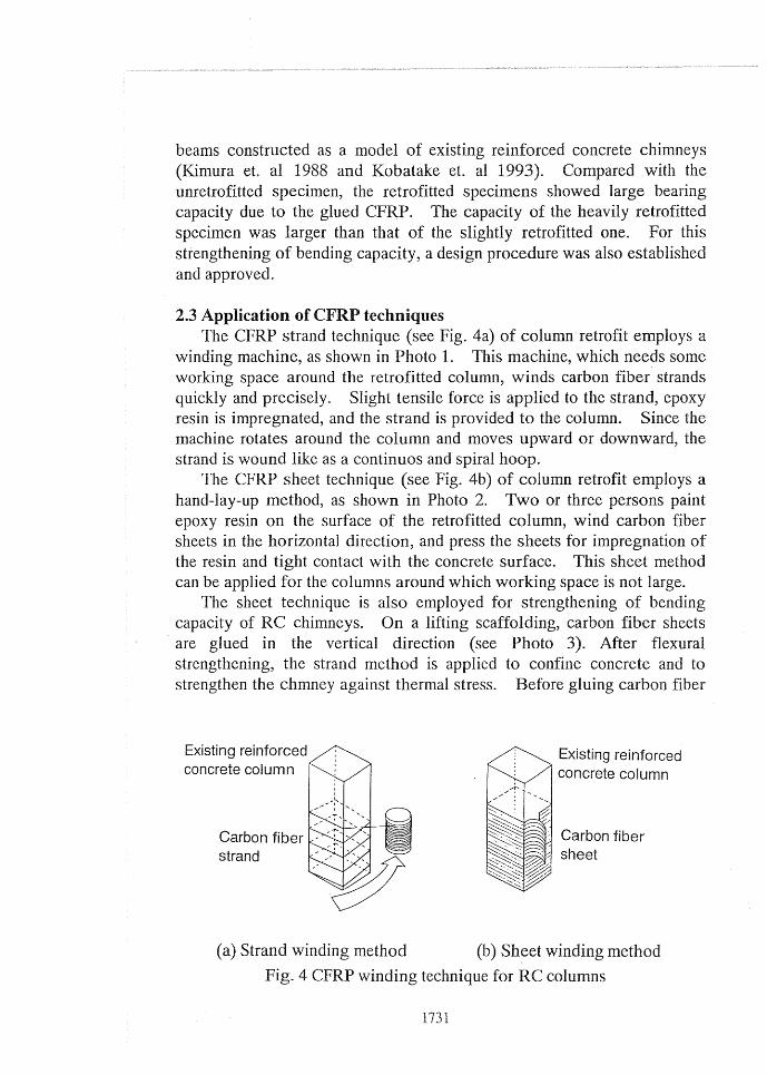
2.3 Application of CFRP techniques The CFRP strand technique (see Fig. 4a) of column retrofit employs a
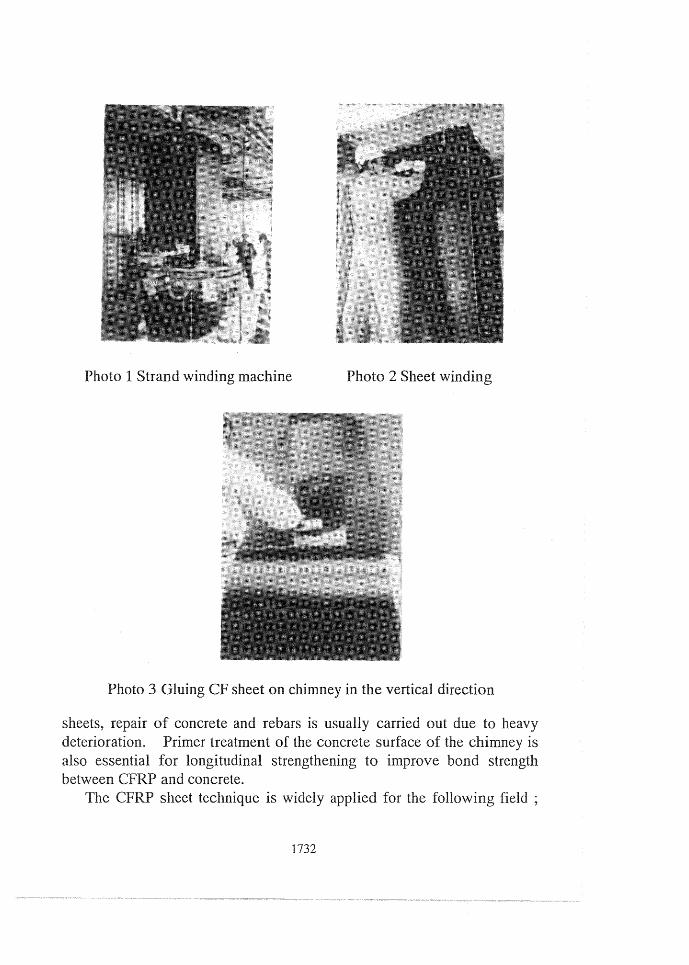
winding machine, as shown in Photo 1. This machine, which needs some working space around the retrofitted column, winds carbon fiber strands quickly and precisely. Slight tensile force is applied to the strand, epoxy resin is impregnated, and the strand is provided to the column. Since the machine rotates around the column and moves upward or downward, the strand is wound like as a continuos and spiral hoop.
The CFRP sheet technique (see Fig. 4b) of column retrofit employs a hand-lay-up method, as shown in Photo 2. Two or three persons paint epoxy resin on the surface of the retrofitted column, wind carbon fiber sheets in the horizontal direction, and press the sheets for impregnation of the resin and tight contact with the concrete surface. This sheet method can be applied for the columns around which working space is not large.
The sheet technique is also employed for strengthening of bending capacity of RC chimneys. On a lifting scaffolding, carbon fiber sheets
· are glued in the vertical direction (see Photo 3). After flexural strengthening, the strand method is applied to confine concrete and to strengthen the chmney against thermal stress. Before gluing carbon fiber
Photo 3 Gluing CF sheet on chimney in the vertical direction
sheets, repair of concrete and rebars is usually carried out due to heavy deterioration. Primer treatment of the concrete surface of the chimney is also essential for longitudinal strengthening to improve bond strength between CFRP and concrete.
The CFRP sheet technique is widely applied for the following
1732
(1) seismic strengthening of shear and bending capacity of bridge columns, (2) seismic strengthening of shear capacity of building beams or walls, and (3) strengthening of bending capacity of beams and slabs for long term loads.
3 Debonding of CFRP from concrete surface
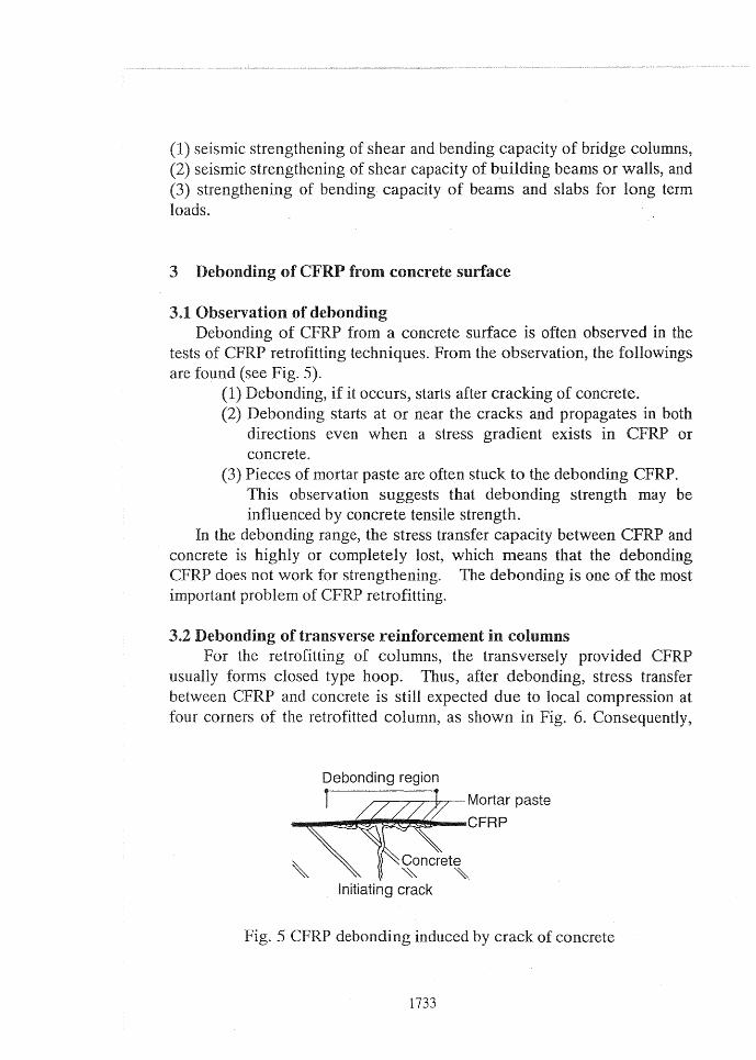
Observation of debonding Debonding of CFRP from a concrete surface is often observed in the
tests of CFRP retrofitting techniques. From the observation, the followings are found (see Fig. 5).
(1) Debonding, if it occurs, starts after cracking of concrete. (2) Debonding starts at or near the cracks and propagates in both
directions even when a stress gradient exists in CFRP or concrete.
(3) Pieces of mortar paste are often stuck to the de bonding CFRP. This observation suggests that debonding strength may be influenced by concrete tensile strength.
In the debonding range, the stress transfer capacity between CFRP and concrete is highly or completely lost, which means that the debonding
does not work for strengthening. The debonding is one of the most important problem of CFRP retrofitting.
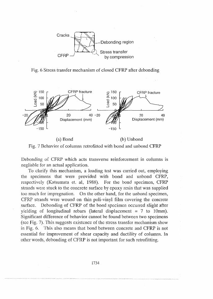
3.2 Debonding of transverse reinforcement in columns For the retrofitting of columns, the transversely provided CFRP
usually forms closed type hoop. Thus, after debonding, stress transfer between CFRP and concrete is still expected due to local compression at four corners of the retrofitted column, as shown in Fig. 6. Consequently,
Fig. 5
Debonding region
~~~-t-r-.,--Mortar paste
~~~~~~~ ........... CFRP
Initiating crack
debonding induced by crack of concrete
1733
Cracks~ ' , --- Debonding region
'---~Stress transfer CFRP by compression
Fig. 6 Stress transfer mechanism of closed CFRP after debonding
CFRP fracture I l
20 40 -20 Displacement (mm)
-150
(a) Bond
z 150
c 100 -0 co 0 _J
-150
CFRP fracture ' ~
20 40 Displacement (mm)
(b) Unbond
Fig. 7 Behavior of columns retrofitted with bond and unbond CFRP
Debonding of CFRP which acts transverse reinforcement in columns is neglisble for an actual application.
To clarify this mechanism, a loading test was carried out, employing the specimens that were provided with bond and unbond CFRP, respectively (Katsumata et. al, 1988). For the bond specimen, CFRP strands were stuck to the concrete surface by epoxy resin that was supplied too much for impregnation. On the other hand, for the unbond specimen, CFRP strands were wound on thin poli-vinyl film covering the concrete surface. Debonding of CFRP of the bond specimen occurred slight after yielding of longitudinal rebars (lateral displacement = 7 to lOmm). Significant difference of behavior cannot be found between two specimens (see Fig. 7). This suggests existence of the stress transfer mechanism show
Fig. 6. This also means that bond between concrete and CFRP is not essential for improvement of shear capacity and ductility of columns. In other words, debonding of CFRP is not important for such retrofitting.
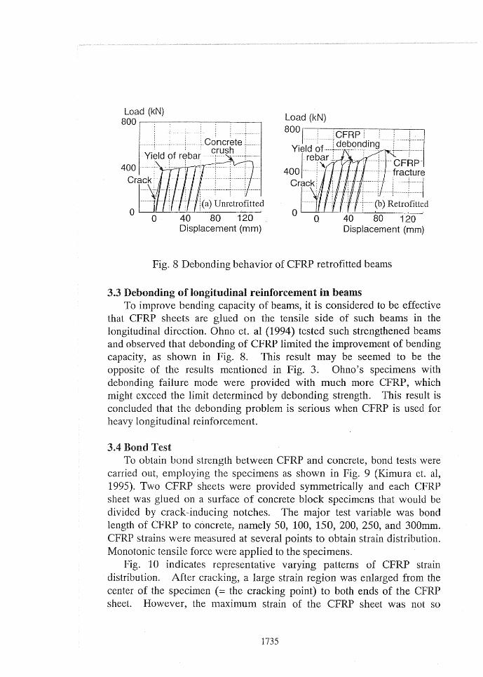
Fig. 8 Debonding behavior of CFRP retrofitted beams
3.3 Debonding of longitudinal reinforcement in beams To improve bending capacity of beams, it is considered to be effective
that CFRP sheets are glued on the tensile side of such beams in the longitudinal direction. Ohno et. al (1994) tested such strengthened beams and observed that debonding of CFRP limited the improvement of bending capacity, as shown in Fig. 8. This result may be seemed to be the opposite of the results mentioned in Fig. 3. Ohno's specimens with debonding failure mode were provided with much more CFRP, which might exceed the limit determined by debonding strength. This result is concluded that the debonding problem is serious when CFRP is used for heavy longitudinal reinforcement.
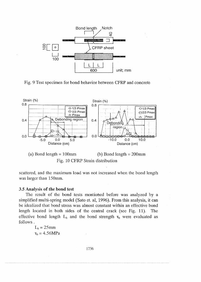
3.4 Bond Test To obtain bond strength between CFRP and concrete, bond tests were
carried out, employing the specimens as shown in Fig. 9 (Kimura et. al, 1995). Two CFRP sheets were provided symmetrically and each CFRP sheet was glued on a surface of concrete block specimens that would be divided by crack-inducing notches. The major test variable was bond length of CFRP to concrete, namely 50, 100, 150, 200, 250, and 300mm. CFRP strains were measured at several points to obtain strain distribution. Monotonic tensile force were applied to the specimens.
Fig. 10 indicates representative varying patterns of CFRP strain distribution. After cracking, a large strain region was enlarged from the center of the specimen ( = the cracking point) to both ends of the CFRP sheet. However, the maximum strain of the CFRP sheet was not so
1735
~CG LJ 100
L I L I 600 unit; mm
Fig. 9 Test specimen for bond behavior between CFRP and concrete
scattered, and the maximum load was not increased when the bond length was larger than 150mm.
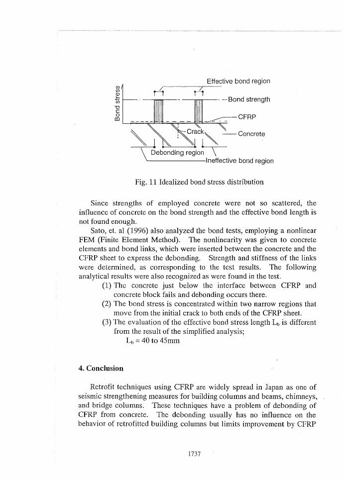
3.5 Analysis of the bond test The result of the bond tests mentioned before was analyzed by a
simplified multi-spring model (Sato et. al, 1996). From this analysis, it can be idealized that bond stress was almost constant within an effective bond length located in both sides of the central crack (see Fig. 11). The effective bond length 4 and the bond strength 'tb were evaluated as follows.
Lb= 25mm i;b = 4.56MPa
1736
Effective bond region
----,.,..,........---- - Bond strength
Fig. 11 Idealized bond stress distribution
Since strengths of employed concrete were not so scattered, the influence of concrete on the bond strength and the effective bond length is not found enough.
Sato, et. al (1996) also analyzed the bond tests, employing a nonlinear FEM (Finite Element Method). The nonlinearity was given to concrete elements and bond links, which were inserted between the concrete and the CFRP sheet to express the debonding. Strength and stiffness of the links were determined, as corresponding to the test results. The following analytical results were also recognized as were found in the test.
(1) The concrete just below the interface between CFRP and concrete block fails and debonding occurs there.
(2) The bond stress is concentrated within two narrow regions that move from the initial crack to both ends of the CFRP sheet.
(3) The evaluation of the effective bond stress length 4 is different from the result of the simplified analysis;
Lb = 40 to 45mm
4. Conclusion
Retrofit techniques using CFRP are widely spread in Japan as one of seismic strengthening measures for building columns and beams, chimneys, and bridge columns. These techniques have a problem of debonding of CFRP from concrete. The debonding usually has no influence on the behavior of retrofitted building columns but limits improvement by CFRP
1737
glued in the longitudinal direction. The debonding behavior and strength was discussed by loading tests and analyses. Future research is still required to obtain more detail knowledge on the debonding, for example, influence of concrete strength, evaluation of bond strength from a fracture mechanics approach, and so on.
· Acknowledgment The authors acknowledge all publishers who gave permission of
reproducing figures.
References
Katsumata, H., Kobatake, Y, and Takeda, (1988) A study of strengthening with carbon fiber for earthquake-resistant capacity of existing reinforced concrete columns, Proc. of 9WCEE, 7, 517-522
Katsumata, H. and Kobatake, Y (1996) Seismic Retrofit with carbon fibers for reinforced concrete columns, Proc. of 11 WCEE, Elsevier Science, Paper No. 293
Kimura, K., Kobatake, Y. et. al (1988) Study on the strengthening R. C. member with carbon fiber (Part 2 Flexural tests of tubular members), Summaries of technical papers of annual meeting, AU, ST, 820-821 (in Japanese)
Kimura, K., Kobatake, Y., and Ohno, S. (1995) Study on the behavior of bond and anchorage between the carbon-fiber sheet and concrete, Journal of Strc. Eng., AIJ, 41B, 527-536 (in Japanese)
Kobatake, Y., Kimura, K., and Katsumata, H. (1993) A retrofitting method for reinforced concrete structures using carbon fiber, FRP Reinforcement for concrete structure: properties and applications (ed. A. Nanni), Elsevier Science, 435-450
Ohno, S., Andoh, H. et. al (1994) Study on bond behavior between CFRP sheets and reinforced concrete, Proc. of 9JEES, 2, 2167-2172 (in Japasese)
Sato, Y., Kimura, K. and Kobatake, Y (1996) Internal fracture simulation for CFRP sheet and concrete, Recent advancement of interfacial materials science on composite material '96, 304-309


![CFRP [Wet-preg]](https://static.documents.pub/doc/80x56/546e6828b4af9faa268b4674/cfrp-wet-preg.jpg)


