Simple procedures and formulas for tracing the characteristics of a spherical Gaussian beam through a trainof lenses or mirrors are described which are analogous to those used in geometrical optics to trace repeatedimages through an optical train.
1. IntroductionIn laboratory experiments with lasers, it is frequently
necessary to follow the properties of a Gaussian beamafter passage through a number of lenses. Often oneis required to design a lens system to create a beam waistof specified diameter at a specified location, for exam-ple, in laser anemometry.
Because on the laboratory scale one is often workingwith a lens in the near field of the incident beam, thebehavior of the beam can be significantly different fromthat which would be anticipated on the basis of geo-metrical optics.
An extreme example of the difference in behaviorbetween Gaussian beams and conventional uniformspherical waves from point sources occurs when thewaist of the incident beam is at the front focal plane ofa positive lens, in which case the emerging beam has awaist at the back focal plane. This is inexplicable onthe basis of geometrical optics, which predicts that apoint object at the front focus yields a collimated beamin the image space, i.e., the image is at infinity. Anotherexample, concerned with the focal shift, i.e., the dif-ference between the position of the image waist for aGaussian beam from its geometrical optics position, isdiscussed in a recent paper by Carter,1 who works interms of the Fresnel number at the lens.
Siegman 2 discusses the properties of Gaussian beamsand treats the problem of following the transformationof such a beam under the action of a train of lenses in ageneral manner using matrix algebra.
In this laboratory, a simple procedure for tracing thecharacteristics of a Gaussian beam through a train oflenses (or mirrors) was devised 3 some years ago and hasproved useful. It generalizes the lens (or mirror) for-mulas of geometrical optics by introducing an additionalparameter, the Rayleigh range of the beam which canbe simply recalculated for each step. Its main virtuelies in the fact that the procedure is analogous to thattraditionally used for following repeated images throughan optical train on the basis of geometrical optics bu twith modified formulas. The Rayleigh range, a prop-erty of the beam incident on each lens, appears to be a
more convenient parameter than the Fresnel numberused by Carter. 1
This paper describes the procedure and formulasadopted and brings out the connection with geometricaloptics. The discussion is given in terms of lenses, bu twith the appropriate sign convention, the results applyequally well for mirrors.
11. Focusing Uniform Spherical Waves
The standard treatment4 of thin lenses (or mirrors)by geometrical optics neglects diffraction and deals withpoint objects and images and uniform spherical waveswhose radii of curvature equal the distances from the
point object or image.The change in wave-front radius of curvature intro-
duced by a lens of focal length f is just l/f (with a suit-able sign convention and assuming identical media oneither side). With the sign conventions of Ref. 4, thestandard thin lens or mirror formula is
s s' f'
The author is with Stanford University, Mechanical EngineeringDepartment, High Temperature Gasdynamics Laboratory, Stanford,California 94305.
Received 23 August 1982.0003-6935/83/050658-04$01.00/0.
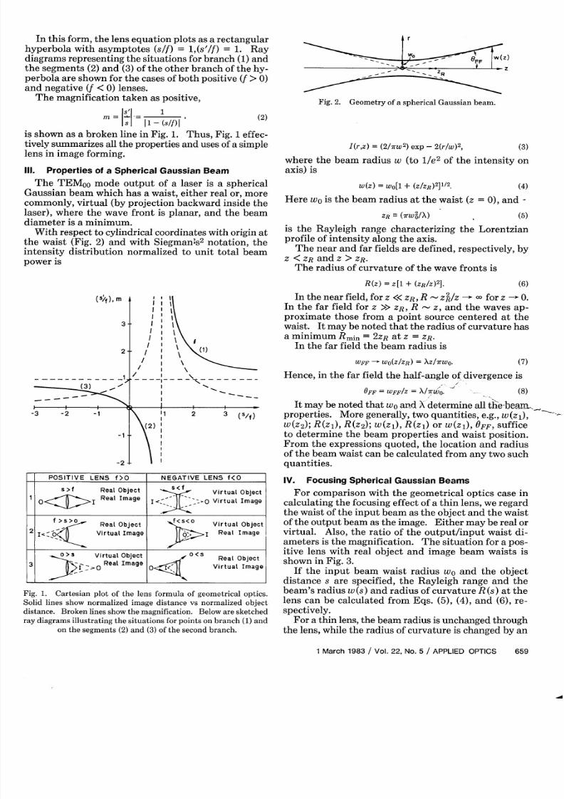
In this form, the lens equation plots as a rectangularhyperbola with asymptotes (s/f) = 1,(s'/f) = 1. Raydiagrams representing the situations for branch (1)andthe segments (2)and (3) of the other branch of the hy-perbola are shown for the cases of both positive (f > 0)and negative (f < 0) lenses.
The magnification taken as positive,
so 1(2)
= 1s l1I- (s/f)|
is shown as a broken line in Fig. 1. Thus, Fig. 1 effec-tively summarizes all the properties and uses of a simplelens in image forming.
Ill. Properties of a Spherical Gaussian Beam
The TEMOO mode output of a laser is a sphericalGaussian beam which has a waist, either real or, morecommonly, virtual (by projection backward inside thelaser), where the wave front is planar, and the beamdiameter is a minimum.
W ith respect to cylindrical coordinates with origin at
the waist (Fig. 2) and with Siegmans2
notation, theintensity distribution normalized to unit total beampower is
Fig. 2. Geometry of a spherical Gaussian beam.
I(r,z) = (2/7rw2) exp -2(r/w)2, (3)
where the beam radius w (to 1/e 2 of the intensity onaxis) is
w(z) = wo[1 + (Z/ZR)2
]1/2. (4)
Here w0 is the beam radius at the waist (z = 0), and -
ZR-( rW2/X) (5)
is the Rayleigh range characterizing the Lorentzianprofile of intensity along the axis.
The near and far fields are defined, respectively, byZ <ZR and z > ZR-
The radius of curvature of the wave fronts is
R(z) = z[1 + (ZR/Z)2].
(S/f), m
3.
2-
I 'II I
-I
I I
/I
/ I
Inthe near field, for z <<ZR, R -z2/Z -) for z - 0.In the far field for z >> ZR, R - z, and the waves ap-proximate those from a point source centered at thewaist. It may be noted that the radius of curvature hasa minimum Rmin = 2
ZR at z = ZR .
In the far field the beam radius is(1)
--.7
-3 -2 -1
-1
-2
1 2 3 (s/f)
(2)
I I
POSITIVE LENS f>O NEGATIVE LENS f<O
s > f Real Object S<f Virtual Object1 O<1> I Real Image I<-?jI ;O Virtual Image
f > >0 Real Object f<s<o Virtual Object
2 i<-0o _ Virtual Image P H I Real Image
>S Virtual Object 0<5 Real Object
3 § -_ o Real Image o Virtual Image
Fig. 1. Cartesian plot of the lens formula of geometrical optics.Solid lines show normalized image distance vs normalized object
distance. Broken lines show the magnification. Below are sketchedray diagrams illustrating the situations for points on branch (1) and
on the segments (2) and (3) of the second branch.
WFF - wo(z/ZR) = XZ/TrWO.
Hence, in the fa r field the half-angle of divergence is
OFF WFF/Z = X/TrU). - (8)
It may be noted that w0 and Xdetermine all thebeany.,properties. More generally, two quantities, e.g., w(z 1 ),w(z2 ); R(zD), R(z 2 ); w(z 1), R(z 1) or w(z1), OFF, sufficeto determine the beam properties and waist position.From the expressions quoted, the location and radiusof the beam waist can be calculated from any two suchquantities.
IV. Focusing Spherical Gaussian Beams
For comparison with the geometrical optics case incalculating the focusing effect of a thin lens, we regardthe waist of the input beam as the object and the waistof the output beam as the image. Either may be real orvirtual. Also, the ratio of the output/input waist di-ameters is the magnification. The situation for a pos-itive lens with real object and image beam waists isshown in Fig. 3.
If the input beam waist radius w and the objectdistance s are specified, the Rayleigh range and thebeam's radius w (s) and radius of curvature R (s) at thelens can be calculated from Eqs. (5), (4), and (6), re-
spectively.For a thin lens, the beam radius is unchanged through
the lens, while the radius of curvature is changed by an
Fig. 3. Geometry of the imaging of a Gaussian beam by a lens shownfor the case of a positive lens and real object and image waists.
(sI/f)
4
3
2
-4 -3 -2 -1
- \V
PARAMETER (zR/f)I
-2
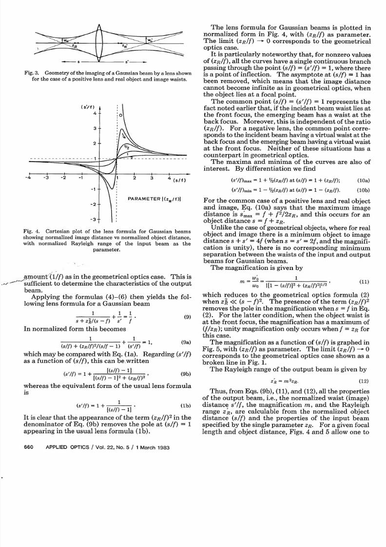
Fig. 4. Cartesian plot of the lens formula for Gaussian beamsshowing normalized image distance vs normalized object distance,with normalized Rayleigh range of the input beam as the
parameter.
amount'(1/f) as in the geometrical optics case. This issufficient to determine the characteristics of the output
beam.Applying the formulas (4)-(6) then yields the fol-
lowing lens formula for a Gaussian beam
1 1 1+ - ~~~~~~~(9)
S+z/(s-f) s f
In normalized form this becomes
(s/f) + (ZR/f)2/(s/f - + = 1, (9a)
which may be compared with Eq. (la). Regarding (s'/f)
as a function of (s/f), this can be.written
(s'/f) = 1 + [(sf) 1][(S/f) 1]2 + (ZR/ff)
(9b)
whereas the equivalent form of the usual lens formulais
(s/) = 1 + l (lb)[(s/f) 1
It is clear that the appearance of the term (ZR/f)2
in thedenominator of Eq . (9b) removes the pole at (s/f) = 1appearing in the usual lens formula (lb).
The lens formula for Gaussian beams is plotted innormalized form in Fig. 4, with (ZR/f) as parameter.The limit (ZR/) - 0 corresponds to the geometricaloptics case.
It is particularly noteworthy that, for nonzero valuesof (ZR/f), all the curves have a single continuous branchpassing through the point (s/f) = (s'/f) = 1,where thereis a point of inflection. The asymptote at (s/f) = 1 has
been removed, which means that the image distancecannot become infinite as in geometrical optics, whenthe object lies at a focal point.
The common point (s/f) = (s'/f) = 1 represents thefact noted earlier that, if the incident beam waist lies atthe front focus, the emerging beam has a waist at theback focus. Moreover, this is independent of the ratio(ZR/f). For a negative lens, the common point corre-sponds to the incident beam having a virtual waist at theback focus and the emerging beam having a virtual waistat the front focus. Neither of these situations has acounterpart in geometrical optics.
The maxima and minima of the curves are also ofinterest. By differentiation we find
(W'/f)max = 1 + '/2(zR/f) at (s/f) = 1 + (ZR/f);
(S'WID-i = 1 - '12(R/f) t (s/f) = 1 - (ZR/f).
(1Oa)
(lOb)
For the common case of a positive lens and real objectand image, Eq. (Oa) says that the maximum imagedistance is Smax = f + f
2/2ZR, and this occurs for an
object distance s = f + ZR.
Unlike the case of geometrical objects, where for realobject and image there is a minimum object to imagedistance s + s' = 4f (when s = s' = 2f, and the magnifi-
cation is unity), there is no corresponding minimumseparation between the waists of the input and outputbeams for Gaussian beams.
The magnification is given by
wI 1
Wo [1 - (S/f)]+ (zR/f)2}1/2
(11)
which reduces to the geometrical optics formula (2)when zA « (s - f)2. The presence of the term (ZR/f)
2
removes the pole in the magnification when s = f in Eq.(2). For the latter condition, when the object waist isat the front focus, the magnification has a maximum of(f/ZR); unity magnification only occurs when f = ZR forthis case.
The magnification as a function of (s/f) is graphed inFig. 5, with (ZR/f) as parameter. The limit (ZR/f) 0
corresponds to the geometrical optics case shown as abroken line in Fig. 1.
The Rayleigh range of the output beam is given by
ZR = m2ZR. (12)
Thus, from Eqs. (9b), (11), and (12), all the propertiesof the output beam, i.e., the normalized waist (image)distance s'/f, the magnification m, and the Rayleighrange ZR , are calculable from the normalized object
distance (s/f) and the properties of the input beamspecified by the single parameter ZR. For a given focallength and object distance, Figs. 4 and 5 allow one to
Fig. 5. Graph of magnification for a Gaussian beam vs normalizedobject distance, with normalized Rayleigh range of the input beam
as the parameter.
quickly assess whether one is working near the geo-metrical optics limit or if there are substantial correc-tions due to working in the near field.
V. Discussion
Because Eq. (9) has been written in terms of theRayleigh range of the input beam, it is not symmetricalwith respect to input and output quantities, as is thegeometrical optics formula. However, the reciprocalrelation in terms of the Rayleigh range of the outputbeam can be written
1 1 1-+ -. (13)
S S + Z2/(S -) f
This is useful for tracing backward to find the propertiesof the input beam when those of the output beam areknown.
It may also be noted that Eq. (9) is used with the usual
sign convention for s, s',and f and with the conventionaldistinctions between real and virtual objects and im-ages.
Commonly, in tracing the beam through an opticalsystem or designing a lens system to create a beam withrequired properties, one has to start with the propertiesof the beam emitted by the laser. Thus, one needs toknow the effective waist position and Rayleigh range ofthe laser beam.
If the output mirror is planar, one knows that thewaist is at the output mirror. Usually the manufacturerspecifies the output beam diameter and far-field di-vergence angle, but it ha s been the author's experiencethat these are not always as stated or known accuratelyenough to determine the Rayleigh range with sufficientprecision. Where possible, it is better to calculate thetheoretical waist position and diameter from the radiiof curvature and separation of the mirrors using thecavity mode equations.2 When the output mirror is no tplanar, allowance should be made for the lens effect ofthe output mirror since it usually has a planar second
surface. This can be done using the method discussedabove to find the position of the virtual waist and theRayleigh range of the output beam.
Finally, it should be noted that, throughout thispaper, it has been assumed that the lens diameter issufficient to not significantly aperture the Gaussianbeam. If significant aperturing effect occurs, the imageposition will not be as given above, and the waist will no thave a truly Gaussian profile. In the limit of a strong
aperturing effect, the beam at the lens will approach theuniform spherical wave assumed in geometrical optics,and the image waist will have the usual Airy diffractionpattern and will occur at the geometrical optics imageposition.
References
1. W. H. Carter, Appl. Opt. 21, 1989 (1982).2. A. E. Siegman, An Introduction o Lasersand Masers (McGraw-
Hill, New York, 1971), Chap. 8.
3. S. A. Self, "Focusing of Gaussian Laser Beams," High-TemperatureGasdynamics Laboratory Memorandum Report No. 3, August 1976
(unpublished).4. F. A. Jenkins and H. E. White, Fundamentals of Optics


![arXiv:1407.0730v4 [physics.optics] 18 Oct 2015 · Key words and phrases. Paraxial wave equation, Green’s function, generalized Fresnel integrals, Airy-Hermite-Gaussian beams, Hermite-Gaussian](https://static.documents.pub/doc/80x56/607256db68e9bf2b096e18e3/arxiv14070730v4-18-oct-2015-key-words-and-phrases-paraxial-wave-equation.jpg)


