70
Engineered for flexibility and performance™ Catalog 860-9 Self-Contained Air Conditioning Systems Type SWP Vintage H with R-410A Refrigerant Capacity: 20 through 130 tons

Engineered for flexibility and performance™
Catalog 860-9 Self-Contained Air Conditioning Systems
Type SWP Vintage Hwith R-410A Refrigerant Capacity: 20 through 130 tons

Introduction . . . . . . . . . . . . . . . . . . . . . . . . . . . . . . . . . 3Continued Leadership in Self-Contained Systems Designs . . . . . . . . . . . . . . . 3
Daikin Self-Contained Systems . . . . . . . . . . . . . . . 4SWP 012–130 Features and Options . . . . . . . . . . . . 4
Cabinet, Casing and Frame . . . . . . . . . . . . . . . . . 6Compressor/ Condensing Section . . . . . . . . . . . . 7Cooling Coil Section . . . . . . . . . . . . . . . . . . . . . . . 8Supply Fan Section . . . . . . . . . . . . . . . . . . . . . . . . 8Acoustical Discharge Plenum . . . . . . . . . . . . . . . 10Variable Air Volume Control . . . . . . . . . . . . . . . . 10Economizer Options . . . . . . . . . . . . . . . . . . . . . . 10Condenser Head Pressure Control . . . . . . . . . . . 11Filter Section . . . . . . . . . . . . . . . . . . . . . . . . . . . . 11Blank Sections . . . . . . . . . . . . . . . . . . . . . . . . . . 11Electrical . . . . . . . . . . . . . . . . . . . . . . . . . . . . . . . 12Heating Section . . . . . . . . . . . . . . . . . . . . . . . . . . 12
System Flexibility with Unit Options . . . . . . . . . . . . 13Selection/Application Flexibility . . . . . . . . . . . . . . 13Arrangement Flexibility . . . . . . . . . . . . . . . . . . . . 13Optimal Discharge Air Temperature . . . . . . . . . . 13Controllers . . . . . . . . . . . . . . . . . . . . . . . . . . . . . . 14R-410A Refrigerant . . . . . . . . . . . . . . . . . . . . . . . 14
MicroTech III Unit Controls . . . . . . . . . . . . . . . . . . . . 15Open Choices Benefits for Easy Integration . . . . 15Alarm Management and Control . . . . . . . . . . . . . 21
Application Considerations . . . . . . . . . . . . . . . . . . . 23General . . . . . . . . . . . . . . . . . . . . . . . . . . . . . . . . 23Unit Location . . . . . . . . . . . . . . . . . . . . . . . . . . . . 23Acoustical Considerations . . . . . . . . . . . . . . . . . . 24Equipment Room . . . . . . . . . . . . . . . . . . . . . . . . 24Ductwork . . . . . . . . . . . . . . . . . . . . . . . . . . . . . . . 24Condenser Water Piping . . . . . . . . . . . . . . . . . . . 25Head Pressure Control . . . . . . . . . . . . . . . . . . . . 25Variable Air Volume . . . . . . . . . . . . . . . . . . . . . . 25Variable Frequency Drives . . . . . . . . . . . . . . . . . 26Duct Static Pressure Sensor Placement . . . . . . . 26Zone Sensor Placement . . . . . . . . . . . . . . . . . . . 26Filtration . . . . . . . . . . . . . . . . . . . . . . . . . . . . . . . 26System Operating Limits . . . . . . . . . . . . . . . . . . . 27Airflow . . . . . . . . . . . . . . . . . . . . . . . . . . . . . . . . . 27Fan Heat . . . . . . . . . . . . . . . . . . . . . . . . . . . . . . . 27Condenser Water Flow . . . . . . . . . . . . . . . . . . . . 27Coil Freeze Protection . . . . . . . . . . . . . . . . . . . . 28Air Density Correction . . . . . . . . . . . . . . . . . . . . . 28Unit Wiring . . . . . . . . . . . . . . . . . . . . . . . . . . . . . 28Terms of Sale . . . . . . . . . . . . . . . . . . . . . . . . . . . 28
Selection Procedure . . . . . . . . . . . . . . . . . . . . . . . . . 29Physical Data . . . . . . . . . . . . . . . . . . . . . . . . . . . . . . 31Performance Data . . . . . . . . . . . . . . . . . . . . . . . . . . . 36
DX Cooling Capacity Data . . . . . . . . . . . . . . . . . 36Waterside Economizer Capacity . . . . . . . . . . . . 44Heating Capacity Data . . . . . . . . . . . . . . . . . . . . 45Component Pressure Drops . . . . . . . . . . . . . . . 46Total Unit Water Pressure Drop . . . . . . . . . . . . . 49Fan Curves . . . . . . . . . . . . . . . . . . . . . . . . . . . . 54
Dimensional Data . . . . . . . . . . . . . . . . . . . . . . . . . . . 61Recommended Clearances . . . . . . . . . . . . . . . . 61
Electrical Data . . . . . . . . . . . . . . . . . . . . . . . . . . . . . . 65Supply Power Wiring . . . . . . . . . . . . . . . . . . . . . 65
Unit Weights . . . . . . . . . . . . . . . . . . . . . . . . . . . . . . . 66
2 Daikin Catalog 860-9
Introduction
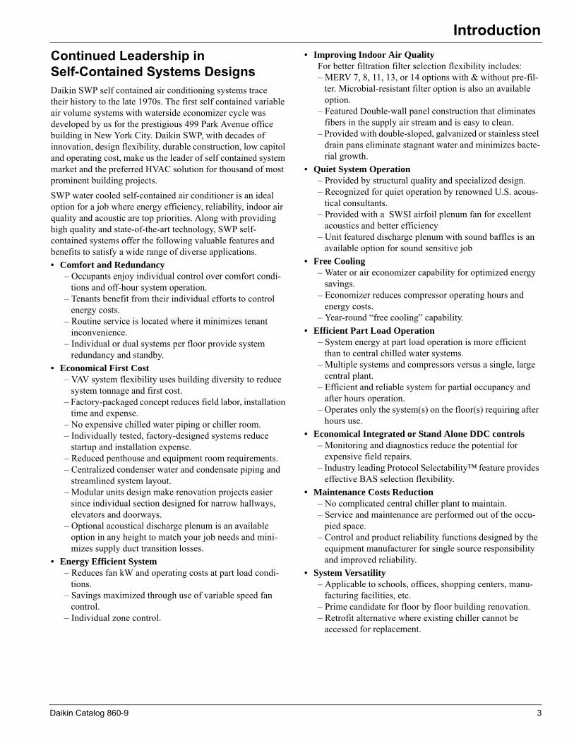
IntroductionContinued Leadership in Self-Contained Systems DesignsDaikin SWP self contained air conditioning systems trace their history to the late 1970s. The first self contained variable air volume systems with waterside economizer cycle was developed by us for the prestigious 499 Park Avenue office building in New York City. Daikin SWP, with decades of innovation, design flexibility, durable construction, low capitol and operating cost, make us the leader of self contained system market and the preferred HVAC solution for thousand of most prominent building projects. SWP water cooled self-contained air conditioner is an ideal option for a job where energy efficiency, reliability, indoor air quality and acoustic are top priorities. Along with providing high quality and state-of-the-art technology, SWP self-contained systems offer the following valuable features and benefits to satisfy a wide range of diverse applications.• Comfort and Redundancy– Occupants enjoy individual control over comfort condi-tions and off-hour system operation.
– Tenants benefit from their individual efforts to control energy costs.
– Routine service is located where it minimizes tenant inconvenience.
– Individual or dual systems per floor provide system redundancy and standby.
• Economical First Cost– VAV system flexibility uses building diversity to reduce
system tonnage and first cost.– Factory-packaged concept reduces field labor, installation
time and expense.– No expensive chilled water piping or chiller room.– Individually tested, factory-designed systems reduce
startup and installation expense.– Reduced penthouse and equipment room requirements.– Centralized condenser water and condensate piping and
streamlined system layout.– Modular units design make renovation projects easier
since individual section designed for narrow hallways, elevators and doorways.
– Optional acoustical discharge plenum is an available option in any height to match your job needs and mini-mizes supply duct transition losses.
• Energy Efficient System– Reduces fan kW and operating costs at part load condi-
tions.– Savings maximized through use of variable speed fan
control.– Individual zone control.
• Improving Indoor Air QualityFor better filtration filter selection flexibility includes:– MERV 7, 8, 11, 13, or 14 options with & without pre-fil-
ter. Microbial-resistant filter option is also an available option.
– Featured Double-wall panel construction that eliminates fibers in the supply air stream and is easy to clean.
– Provided with double-sloped, galvanized or stainless steel drain pans eliminate stagnant water and minimizes bacte-rial growth.
• Quiet System Operation– Provided by structural quality and specialized design.– Recognized for quiet operation by renowned U.S. acous-
tical consultants.– Provided with a SWSI airfoil plenum fan for excellent
acoustics and better efficiency– Unit featured discharge plenum with sound baffles is an
available option for sound sensitive job• Free Cooling
– Water or air economizer capability for optimized energy savings.
– Economizer reduces compressor operating hours and energy costs.
– Year-round “free cooling” capability.• Efficient Part Load Operation
– System energy at part load operation is more efficient than to central chilled water systems.
– Multiple systems and compressors versus a single, large central plant.
– Efficient and reliable system for partial occupancy and after hours operation.
– Operates only the system(s) on the floor(s) requiring after hours use.
• Economical Integrated or Stand Alone DDC controls – Monitoring and diagnostics reduce the potential for
expensive field repairs.– Industry leading Protocol Selectability™ feature provides
effective BAS selection flexibility.• Maintenance Costs Reduction
– No complicated central chiller plant to maintain.– Service and maintenance are performed out of the occu-
pied space.– Control and product reliability functions designed by the
equipment manufacturer for single source responsibility and improved reliability.
• System Versatility– Applicable to schools, offices, shopping centers, manu-
facturing facilities, etc.– Prime candidate for floor by floor building renovation.– Retrofit alternative where existing chiller cannot be
accessed for replacement.
Daikin Catalog 860-9 3
Daikin Self-Contained Systems
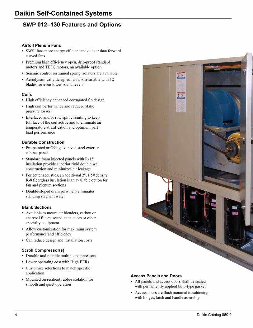
ained SystemsSWP 012–130 Features and OptionsAirfoil Plenum Fans• SWSI fans more energy efficient and quieter than forward
curved fans• Premium high efficiency open, drip-proof standard
motors and TEFC motors, an available option• Seismic control restrained spring isolators are available• Aerodynamically designed fan also available with 12
blades for even lower sound levels
Coils• High efficiency enhanced corrugated fin design• High coil performance and reduced static
pressure losses• Interlaced and/or row split circuiting to keep
full face of the coil active and to eliminate air temperature stratification and optimum part load performance
Scroll Compressor(s) • Durable and reliable multiple compressors• Lower operating cost with High EERs • Customize selections to match specific
application• Mounted on resilient rubber isolation for
smooth and quiet operation
Blank Sections• Available to mount air blenders, carbon or
charcoal filters, sound attenuators or other specialty equipment
• Allow customization for maximum system performance and efficiency
• Can reduce design and installation costs
Durable Construction• Pre-painted or G90 galvanized steel exterior
cabinet panels• Standard foam injected panels with R-13
insulation provide superior rigid double wall construction and minimizes air leakage
• For better acoustics, an additional 2", 1.5# density R-8 fiberglass insulation is an available option for fan and plenum sections
• Double-sloped drain pans help eliminates standing stagnant water
Access Panels and Doors• All panels and access doors shall be sealed
with permanently applied bulb-type gasket• Access doors are flush mounted to cabinetry,
with hinges, latch and handle assembly
4 Daikin Catalog 860-9

Daikin Self-Contained Systems
MicroTech® III Control System• Factory-installed and tested to help minimize costly field
commissioning.• Open Choices™ feature for easy integration into the BAS of
your choice using open, standard protocols such as BACnet® or LONTALK®.
• Easily accessed for system diagnostics and adjustments via a keypad/display on unit.
• Optionally add a remote keypad and display that is identical to the unit mounted user interface.
Multiple Filter Options• 2" 30% (MERV7) and 75% (MERV13) filters• 4" 30% (MERV8), 65% (MERV11), 75% (MERV13)
and 85% (MERV14) longer lasting filters available• 4" primary filters also available with 2" or 4" with
pre-filter
Economizer Options• Waterside economizer effectively uses low cooling tower
water temperatures to offload compressor operation• An airside economizer control package is available for
controlling field installed mixing dampers capable of 100% outside airflow.
Refrigerant Circuits• Suction and discharge service valves, an available
option, to isolate each compressor• Hot gas bypass, an available option, on units with
two refrigerant circuits Shell and Tube Condensers• Carbon steel Shell and Tube Condenser , non-
ferrous water channels and enhanced tubing for high performance
• Integral sub-cooling circuit is provided as standard to maximize efficiency
• Mechanically cleanable condenser and water piping is rated for standard 300 psig waterside working pressure & 450 psig is an available option
• Two-way valve for head pressure control is available for low condenser water temperatures
Factory-Mounted Variable Frequency Drives• Controlling fan motor speed can lower fan operating
costs and sound levels• All VFD selections are plenum rated• Manually activated bypass contactor is available to
allow system operation in the event of drive service
Daikin Catalog 860-9 5

Daikin Self-Contained Systems
Daikin Self -Contained SWP systems are built to perform, with features and options that provide for lower installed and operating costs, good indoor air quality, quiet operation and longevity.Cabinet, Casing and Frame• Unit base constructed of 15-gauge and 10-gauge galvanized
steel for vibration control and rigging strength. • Heavy-duty lifting brackets strategically placed for balanced
cable or chain hook lifting.
Figure 1: Low Leak Gasketed Frame and Foam Panels
• Low leak gasketed frame channels minimize air leakage and eliminates metal-to-metal contact between paneling and frame work. Air leakage is only 0.5 cfm/square foot at 5" cabinet pressure.
• Unit cabinet constructed with foam insulation standard and heavy gauge [pre-painted] [galvanized steel] exterior panels for long equipment life.
• All sections have galvanized steel internal lining. • 2-inch thick panels and access doors are thermal broke
double wall assembly, with [R-13 foam] [R-8 fiberglass].• System components strategically located for ease of
inspection, serviceability and maintenance.• Refrigeration components positioned out of the airstream so
adjustments and readings can be made without disrupting system operation.
• Access doors flush mounted to cabinetry, with hinges, latch and handle assembly.
• Doors on positive pressure sections are provided with secondary latches to relieve pressure and prevent injury upon access.
Figure 2: Hinged Access Doors with double latches
6 Daikin Catalog 860-9

Daikin Self-Contained Systems
Modular Design• Optional modular construction unit shipped with a nitrogenholding charge.• Four distinct sections; coil/access section, supply fan
section, compressor/condenser section and the control panel.
Figure 3: SWP Modular Sections
Compressor/ Condensing Section
Compressors• All units feature multiple reliable scroll compressors for
efficient system part load control, quiet operation and system redundancy.
• Suction and discharge service valves and gauge ports, available option, on each compressor.
• Individual branch circuit fusing protects each compressor. • To prevent compressor short cycling, MicroTech® III
control system incorporates timing functions.• Compressors mounted on resilient rubber isolation for
smooth and quiet operation.
Figure 4: Compresors
• Insulated and segregated condensing section from the air handling section to avoid transmission of noise to the circulated air stream.
• Each refrigerant circuit is furnished with filter-drier, liquid moisture indicator/sight glass, thermal expansion valve, liquid line shutoff valve with charging port, high pressure relief device and high and low pressure cutouts.
• If any compressor is made inoperable, the remaining compressors are still allowed to operate.
• Thermal expansion valve capable of modulation from 100-25% of its rated capacity.
• Hot gas bypass also available on units with two refrigerant circuits.
Condensers• All units feature carbon steel mechanically cleanable shell
and tube condenser.• Includes non-ferrous water channels and enhanced tubing
for high performance.• Serves an independent refrigerant circuit and includes a
spring loaded high pressure relief valve• Integral sub-cooling circuit provided as standard to
maximize efficiency.
Figure 5: Condensers
• All units are leak tested, evacuated and shipped with a [full operating charge of R-410A] [for modular design nitrogen holding charge] and POE oil.
• Condenser assembly and all factory water piping rated for a waterside working pressure of 300 psig as standard [450 psig] tested before shipment.
• Provided with a single supply and return water connections• Unit available in both right-hand and left-hand piping
locations.• Optional two-way valve provides accurate head pressure
control for condenser entering water temperatures as low as 40ºF.
Control PanelCoil/Access Section
Supply Fan Section
Compressor/Condenser Section
Base Plates
Daikin Catalog 860-9 7

Daikin Self-Contained Systems
Cooling Coil Section• Large face area coils with high efficiency, enhanced copper
tubing and ripple corrugated aluminum fins.
• Features interlaced and/or row split circuiting to keep the full face of the coil active and eliminate air temperature stratification and optimum part load performance.
Figure 6: Evaporator Coil Circuiting
• 5 or 6 row evaporator coil with 12 fins/ inch spacing and multiple face areas allows a custom match to specific design loads.
• Provides low air pressure drop, high full and part load operating efficiencies.
• Mounted in a [galvanized] [stainless steel ] cross broke and double sloped drain pan with a full 2 inches of insulation.
• Compressor staging sequenced to take maximum advantage of available coil surface.
• Each evaporator coil circuit furnished with a wide range thermostatic expansion valve with an adjustable superheat setting and external equalizer.
• An intermediate drain pan in the coil bank helps to provide condensate removal without carryover.
Figure 7: Cooling Coil Section Shown
Supply Fan Section• Single width, single inlet (SWSI) airfoil supply air fan
selections provide efficient, quiet operation at wide ranging static pressure and air flow requirements.
• Each fan assembly is dynamically trim balanced at the factory for quiet operation before shipment.
• All fan drives are factory sized according to job specific airflow, static pressure, and power requirements.
• For seismic sensitive regions, spring fan isolators are available with seismic restraints.
• 150% service factor drives extend service life of the fan belts. Drive components and fan bearings are easily accessed for periodic maintenance.
• Mounted on 2 inch deflection spring isolators for excellent isolation effectiveness.
• Solid steel shafts rotating in 200,000 hour pillow block ball bearings with grease fittings.
• Motor availability includes premium efficiency, open, drip-proof, and totally enclosed selections; EPACT compliant premium efficiency selections.
Figure 8: Airfoil Fan
Refrig. Flow Ckt 1Refrig. Flow Ckt 2
Ckt 2
Ckt 1
Ckt 1
Ckt 1
Ckt 1
Ckt 1
Ckt 1
Ckt 1
Ckt 1
Ckt 2
Ckt 2
Ckt 2
Ckt 2
Ckt 2
Ckt 2
Ckt 2
Airflow
Cooling Coils
8 Daikin
Self-Contained Systems
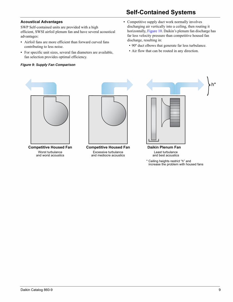
Acoustical AdvantagesSWP Self-contained units are provided with a high efficient, SWSI airfoil plenum fan and have several acoustical advantages:• Airfoil fans are more efficient than forward curved fanscontributing to less noise.• For specific unit sizes, several fan diameters are available,
fan selection provides optimal efficiency.
• Competitive supply duct work normally involves discharging air vertically into a ceiling, then routing it horizontally, Figure 10. Daikin’s plenum fan discharge has far less velocity pressure than competitive housed fan discharge, resulting in:• 90º duct elbows that generate far less turbulance.• Air flow that can be routed in any direction.
Figure 9: Supply Fan Comparison
Daikin Plenum FanLeast turbulance
and best acoustics
* Ceiling heights restrict “h” and increase the problem with housed fans
Competitive Housed FanExcessive turbulance
and mediocre acoustics
Competitive Housed FanWorst turbulance
and worst acoustics
h*
Daikin Catalog 860-9 9

Daikin Self-Contained Systems
Acoustical Discharge PlenumDaikin offers an optional acoustical discharge plenum, Figure 10, that minimizes supply duct transition losses and noise:• Plenum fans pressurize the entire cabinet and have nosignificant plenum air pressure drop (housed fans have expansion, contraction and 90º elbow losses).
• Discharge plenums offered in any height to match ceiling height.
• Custom size duct connections are available on any size plenum.
Discharge Plenum with Foam Insulation and Sound BafflesOptional discharge plenum with foaminjected panels can be provided with the additional sound attenuating baffle option consisting of:• Additional 2" of fiberglass insulation.• Perforated liners, Figure 11.
Figure 10: Acoustical Discharge Plenum
Figure 11: Foam Insulation and Sound Baffles
Variable Air Volume Control• Energy saving advanced technology variable frequency
drive (VFD), fan speed control is available with the convenience and cost savings of factory mounting and testing.
Figure 12: Variable Frequency Drive Controller
• All VFD selections are plenum rated and are conveniently mounted within the control panel.
• MicroTech III controls provide advanced duct static pressure control and controlled by either single or two-duct static pressure sensors.
• A manually activated bypass contactor is available to allow system operation even in the event of drive service.
• All VAV systems include an adjustable, duct high-limit switch to protect duct work from excessive pressure.
Economizer Options
Waterside Economizer• An energy saving, waterside economizer package, an
available option on all return air unit.• Includes factory mounted 4-row [chemically cleanable coil]
[mechanically cleanable coil], control valves and piping. • Rated for 300 psig as standard [450 psig] waterside working
pressure and the entire coil and piping assembly is factory leak tested.
• Factory integrated MicroTech III controller to control economizer operation and maximize free cooling potential.
• Unit enables economizer operation whenever cooling tower water temperature is less than the unit entering air temperature by a field adjustable value, generally 5-7°F.
Daikin Optional Plenum
“h” can be variedto match ceiling height
h
Competition
Expansion Loss
90° Elbow Loss
Standard Exterior Galvanized Surface
Standard Galvanized Liner
Standard Injected Foam PanelOptional Fiberglass Insulation
Perforated LinerInterior Optional
10 Daikin Catalog 860-9

Self-Contained Systems
• To save energy with a variable pumping system controlvalves operation can be selected to maintain full flow through the unit at all times or to isolate the unit from the condenser water loop when there is no call for cooling.
• To extend free cooling savings, economizer operation can be enabled during mechanical cooling.
• Unit enables mechanical cooling only when the economizer valve is driven 90% open and cooling load is not satisfied.
• Economizer control will maintain full free cooling capability until disabled by the economizer changeover set point.
• To help protect against coil freeze-up an optional factory mounted freeze stat is available.
Figure 13: Mechanically Cleanable Waterside Economizer Coil
Airside Economizer• A mixing box containing outdoor air, return air and exhaust
air dampers are available using the Daikin Vision™ air handling unit platform.
• Factory integrated MicroTech III controller controls economizer operation and maximize free cooling potential.
• Airside economizer control package available to control field installed mixing dampers capable of 100% outside airflow.
• Unit enables economizer operation whenever outside air enthalpy, comparative enthalpy or dry bulb temperature changeover provides control flexibility to bring in most amount of outside air for free cooling.
• Economizer damper control actuator modulates in response to the cooling load.
• MicroTech III controller positions outside air damper to maintain minimum ventilation requirements when economizer is not in operation.
• To extend free cooling savings, economizer operation can be enabled during mechanical cooling.
• Unit enables mechanical cooling only when the economizer damper is driven 90% open and cooling load is not satisfied.
• Economizer control will maintain full free cooling capability until disabled by the economizer changeover set point.
Condenser Head Pressure Control• Unit requires condenser head pressure control for
applications where a waterside economizer package is not being used and entering condenser water temperatures can be less than 55°F.
• Optional two-way valve provides accurate head pressure control for condenser entering water temperatures as low as 40degree F
Filter Section• Selection flexibility includes face loaded rack with non-
gasketed frames and filter clips.• Unit features 2-inch filter option available in 30% (MERV 7)
& 75% (MERV 13) nominal efficiency • Longer lasting 4-inch filters higher filtration option is
available in 30% (MERV 8) & 65% (MERV 11), 75% (MERV 13) & 85% (MERV 14) nominal efficiency with and without 2-inch or 4-inch 30% pre-filter.
Figure 14: 4 Inch Filters
Blank Sections• Available to mount air blenders, pre-heat coils, sound
attenuators or other specialty equipment using the Daikin Vision™ air handling unit platform and shipped loose.
• Allow customization for maximum system performance and efficiency and reduce design and installation costs.
Mechanically CleanableEconomizer Coil
Daikin Catalog 860-9 11

Daikin Self-Contained Systems
Electrical• Units are completely wired and tested at the factory priorshipment.• Wiring complies with NEC requirements and all applicable
UL standards.• For ease of use, wiring and electrical components are
number coded and labeled according to the electrical diagram whenever applicable.
• Supply air fan motors, compressor motors and electric heat all branch circuits have individual short circuit protection.
• Control circuit power is supplied through a factory installed, low voltage transformer.
• The supply fan motor circuit includes a three phase contactor and ambient compensated overload protection with manual reset.
• Each refrigerant circuit includes both a high and low pressure cutout switch.
• A terminal block is provided for the single, main power connection and a terminal board is provided for low voltage control wiring.
• A factory mounted, non-fused main circuit interrupter is available for disconnecting the main electrical power to the unit.
• Dual power blocks or disconnect switches are available to accommodate requirements for standby, emergency power supplies.
Heating Section
Hot Water Heat• Multiple coil selections offered to size heating output to
application needs.• Hot water coils are 5/8-in. O.D. copper tube/ aluminum fin
design with patented HI-F5 fins.• Rated in accordance with ARI Standard 430.• Pre-heating control fully integrated into the unit’s
MicroTech III control system is available using the Daikin Vision™ air handling unit platform.
• Available with factory-mounted freezestat.
Steam Heat• Steam heating coils are 5/8-in. O.D. copper tube/aluminum
fin jet distributing type with patented HI-F5 fin design.• Rated in accordance with ARI Standard 430.• Multiple different steam coil selections offered to size
heating output to application needs.• Pre-heating control fully integrated into the unit’s
MicroTech III control system is available using the DaikinVision™ air handling unit platform.
• Available with factory-mounted freezestat.
Electric Heat• Factory assembled, installed and tested.• Two stage capability for application flexibility.• Durable low watt density nickel chromium elements for
longer life.• Entire heat bank protected by a linear high limit control with
each heater element protected by an automatic reset high limit control.
• Fuses provided in each branch circuit.
12 Daikin Catalog 860-9

System Flexibility with Unit Options
System Flexibility with Unit OptionsAlong with providing high quality and state-of-the-art innovation, SWP self-contained systems offer customized flexibility to satisfy a wide range of diverse applications.
Selection/Application FlexibilityNominal cooling capacities range from 12 to 130 tons. In addition, all units offer multiple compressor selections to meet exacting system requirements. The flexibility to optimize the self-contained system to fit the application is a Daikin SWP advantage. Available system applications include the following:
• VAV discharge air temperature control with static pres-sure control.
• Discharge air temperature control with constant air vol-ume.
• Constant volume, zone temperature control.• 100% outside air control.• Dehumidification control, with or without reheat control.
In addition to compressor/coil flexibility, SWP systems offer single width, single inlet, air foil fans with factory-mounted variable frequency drives for maximizing VAV system fan performance. High efficiency fan capability coupled with extensive compressor flexibility provide the right system selection for the application.
Arrangement FlexibilityAll SWP systems offer the flexibility of right-hand and left-hand piping and control panel arrangements and multiple fan
discharge orientations. Piping and fan arrangement flexibility can simplify mechanical equipment room arrangement, improve installation costs, and total system performance.
Optimal Discharge Air TemperatureMore and more system engineers are designing optimal discharge air temperature systems to improve system performance and system first cost; the Daikin SWP provides the flexibility to do it successfully. Optimal discharge air temperature systems are designed to provide unit leaving air temperature selections of 52°F to 53°F versus more conventional systems that supply air at temperatures closer to 58°F. This five to six degree reduction in air temperature to the room diffusers can subsequently reduce the required supply air volume to the room by 20% to 25%.The benefits of optimal discharge air temperature systems become quite apparent with a look at the advantages offered with reduced supply air cfm airflow:
• Reduced first cost and installation cost by allowing smaller duct sizes and a smaller air distribution system.
• Reduced bhp requirements. Depending on changes in duct size and the resulting total static pressure, a 20% reduction in supply air cfm can reduce fan bhp require-ments by 25% or more.
• Reduced fan sound power generation and a quieter room environment.
• Reduced equipment room size may be possible due to using a physically smaller unit size.
• Filtration Flexibility.
Daikin Catalog 860-9 13
System Flexibility with Unit Options
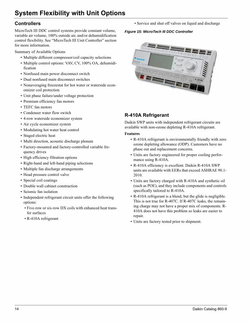
ControllersMicroTech III DDC control systems provide constant volume, variable air volume, 100% outside air, and/or dehumidification control flexibility. See “MicroTech III Unit Controller” section for more information.Summary of Available Options• Multiple different compressor/coil capacity selections• Multiple control options: VAV, CV, 100% OA, dehumidi-
fication• Nonfused main power disconnect switch• Dual nonfused main disconnect switches• Nonaveraging freezestat for hot water or waterside econ-
omizer coil protection• Unit phase failure/under voltage protection• Premium efficiency fan motors• TEFC fan motors• Condenser water flow switch• 4-row waterside economizer system• Air cycle economizer system• Modulating hot water heat control• Staged electric heat• Multi direction, acoustic discharge plenum• Factory-mounted and factory-controlled variable fre-
quency drives• High efficiency filtration options• Right-hand and left-hand piping selections• Multiple fan discharge arrangements• Head pressure control valve• Special coil coatings• Double wall cabinet construction• Seismic fan isolation• Independent refrigerant circuit units offer the following
options:• Five-row or six-row DX coils with enhanced heat trans-
fer surfaces• R-410A refrigerant
• Service and shut off valves on liquid and discharge
Figure 15: MicroTech III DDC Controller
R-410A RefrigerantDaikin SWP units with independent refrigerant circuits are available with non-ozone depleting R-410A refrigerant. Features
• R-410A refrigerant is environmentally friendly with zero ozone depleting allowance (ODP). Customers have no phase out and replacement concerns.
• Units are factory engineered for proper cooling perfor-mance using R-410A.
• R-410A efficiency is excellent. Daikin R-410A SWP units are available with EERs that exceed ASHRAE 90.1- 2010.
• Units are factory charged with R-410A and synthetic oil (such as POE), and they include components and controls specifically tailored to R-410A.
• R-410A refrigerant is a blend, but the glide is negligible. This is not true for R-407C. If R-407C leaks, the remain-ing charge may not have a proper mix of components. R-410A does not have this problem so leaks are easier to repair.
• Units are factory tested prior to shipment.
14 Daikin Catalog 860-9
MicroTech III Unit Controls
MicroTech III Unit ControlsDaikin SWP systems continue to provide industry leading performance, equipped with a complete MicroTech III control system. In addition to providing stable, efficient temperature, and static pressure control, the controller is capable of providing comprehensive diagnostics, alarm monitoring, and alarm specific component shutdown if critical equipment conditions occur. The unit controllers are factory mounted and configured for stand-alone operation or integration with a building automation system (BAS) through an optional communication module with our Open Choices feature.
Open Choices Benefits for Easy IntegrationEasy, low cost integration into most building automation systems without costly gateway panels.• Flexibility to select either BACnet® or LONWORKS®
communication. Units are LonMark® 3.4 certified with the appropriate communications module for LONWORKS networks.
• Comprehensive unit control and status information is available at the BAS regardless of communication protocol.
• Long-term choices for equipment adds or replacements, and for service support.
• Flexible alarm notification and prioritization with Intrinsic Alarm Management (BACnet).
• Simplified BAS integration with the ability to set network parameters at the unit controller, reducing installation time and costs.
• Easy monitoring and troubleshooting of communication status from the unit controller to the BAS.
ComponentsEach SWP self-contained system is equipped with a complete MicroTech III unit control system that is pre-engineered, preprogrammed, and factory tested prior to shipment. Each of the MicroTech III unit control systems is composed of several components that are individually replaceable for ease of service. These components include:
• Unit controller with user interface display and navigation wheel
• Optional expansion modules• Communication module (optional)• Pressure transducers• Unit-mounted temperature sensors• Zone temperature sensor packages• Humidity sensor
Main Control Board (MCB)The main control board (MCB) contains a microprocessor that is preprogrammed with the software necessary to control the unit. This provides that schedules, set points and parameters are not lost, even during a long-term power outage. The microprocessor board processes system input data and then determines and controls output responses. An RS-232 communication port is provided as standard to allow for direct or modem access with a PC-based service tool.
Expansion ModulesThese boards are used to expand the input and output capability of the unit controller. Each board communicates via serial data communications. These microprocessor based boards provide independent operation and alarm response even if communication is lost with the unit controller.
Communication ModuleAn optional communication module provides the means to factory or field configure MicroTech III unit controls for interoperability with an independent BAS. Communication modules are available to support industry recognized communication protocols including BACnet MS/TP, BACnet/ IP and LONWORKS.
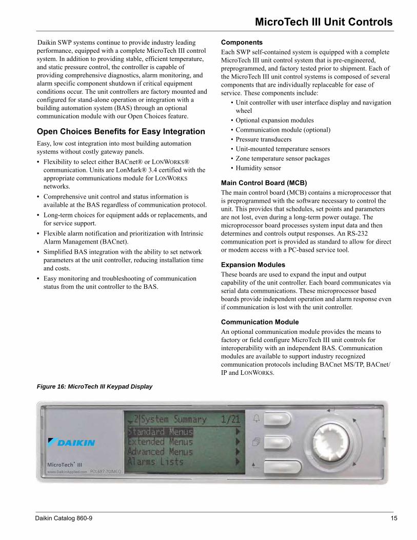
Figure 16: MicroTech III Keypad Display
www.DaikinApplied.com
Daikin Catalog 860-9 15

MicroTech III Unit Controls
Keypad/DisplayAll MicroTech III unit controllers include a push/pull navigation wheel and display. The display is a supertwist nematic type with highly visible black characters on a yellow background. The 5-line by 22-character format allows for easy to understand plain English display messages. All operating conditions, system alarms, control parameters and schedules can be monitored from the keypad/display. If the correct password has been entered, any adjustable parameter or schedule can be modified from the keypad.Temperature and Humidity SensorsWith the exception of the zone, outside air and return air sensors, all temperature sensors are factory installed and tested. Zone sensor packages are available to suit any application. A humidity sensor is available for field installation.
Static Pressure TransducersAll pressure transducers are factory installed and tested. Connection and routing of field-supplied sampling tubes is done at time of unit installation.
Zone Temperature SensorsTwo optional zone temperature sensors are available:
• Zone sensor with tenant override switch• Zone sensor with tenant override switch and remote set
point adjustment
Timed tenant override is a standard MicroTech III control feature.Zone sensors are required for the controller’s purge cycle, space reset of supply air set point, and night setback or setup features. All zone sensors are field installed with field wiring terminated at a separate, clearly marked terminal strip.
Stand-alone Controller FeaturesMicroTech III applied rooftop unit controls include all of the essential features required to make them capable of completely independent, stand-alone operation.
Internal Time ClockAn internal, battery-backed time clock is included in the MicroTech III unit controller. Current date and time can be quickly and easily set at the user interface keypad.
Internal ScheduleSeven daily schedules and one holiday schedule can be entered at the keypad of all unit controllers. For each of these eight schedules, one start and one stop time can be entered. Up to 10 holiday periods, of any duration, can be designated. The unit will automatically run according to the holiday schedule on the holiday dates. To handle special occasions, an additional ‘one event’ schedule can also be used.In lieu of its internal schedule, the unit can be operated according to a network schedule from a BAS.
External Time Clock or Tenant Override InputAn input is supplied that can be used to accept a field wired start/stop signal from a remote source. An external time clock, a tenant override switch, or both may be connected. Whenever the external circuit is closed, the controller overrides the internal schedule (if activated) and places the unit into the occupied mode.If the internal schedule or a BAS network schedule is used, field wiring is not required.
Timed Tenant OverrideOff-hour operation flexibility is a must in today’s office environments and even stand-alone MicroTech III controls handle it with ease. When unit operation is desired during unoccupied hours, initiate timed tenant override by pressing the tenant override button on either of the optional zone sensor packages. The unit then starts and runs in the occupied mode for a keypad-adjustable length of time (up to five hours). If the button is pressed again while the unit is operating, the timer resets to the full time allowance without interrupting unit operation. Tenant override operation also can be initiated by a BAS.
Three Remote Set Point Adjustment Options1 Remote user interface option (RUI). 2 Building automation system (BAS). See “Open Choices
Benefits for Easy Integration” on page 15.3 All constant air volume-zone temperature control (CAV-
ZTC) unit controllers include an input that can be used to remotely adjust the zone cooling and heating set points. To use this feature, wire the optional zone sensor package with set point adjustment to the controller. The remote set point adjustment feature can be enabled or disabled from the keypad at any time. When enabled, remote set point adjustment is available even if the return temperature is selected to be the Control Temperature.
16 Daikin Catalog 860-9
MicroTech III Unit Controls
Auto/Manual Operation SelectionAutomatic or manual operation can be controlled either remotely or at the keypad.All controllers include three inputs that can be used to enable or disable cooling, heating, and fan operation from remote switches. With the “heat enable” and “cool enable” terminals, the operator can enable cooling, heating, or both as desired. Using the system “off” terminals, the operator can disable the fans, and thus the entire unit.From the keypad, there are a variety of occupancy and auto! manual control mode selections available to the operator:• Occupancy modes– Auto– Occupied– Unoccupied– Bypass (tenant override)
• Control modes– Off manual– Auto– Heat/cool– Cool only– Heat only– Fan only
Compressor Lead-lag SelectionAll unit controllers are capable of automatic compressor, lead-lag control.
Waterside Economizer ChangeoverOn units equipped with a waterside economizer package, the MicroTech III unit controller includes an internal changeover strategy that compares entering cooling tower water temperature to the unit’s mixed air temperature. If the entering water temperature is less than the mixed air temperature by a field-adjustable differential (typically 5°F to 7ºF), the economizer control valve modulates in response to the cooling load.
Airside Economizer Changeover SelectionOn units equipped with an economizer, there are three methods of determining whether the outdoor air is suitable for free cooling: two methods sense enthalpy (dry bulb temperature and humidity) and one senses outdoor air dry bulb temperature.The two enthalpy changeover methods use external, factory installed controls. One compares the outdoor ambient enthalpy to a set point; the other is a solid state device that compares the outdoor ambient enthalpy to the return air enthalpy. This
comparative enthalpy control can improve total economizer performance.All unit controls include an internal dry bulb changeover strategy that can be selected at the keypad. When this method is selected, the controller compares the outdoor air dry-bulb temperature to a keypad programmable set point. The external enthalpy control input is then ignored.
Cooling and Heating Lockout ControlAll unit controls include separate keypad programmable set points for locking out mechanical cooling and heating. Mechanical cooling is locked out when the outdoor temperature is below the cooling lockout set point; heating is locked out when the outdoor temperature is above the heating lockout set point. This feature can save energy cost by eliminating unnecessary heating and cooling during warm-up or cool-down periods or when the outdoor air temperature is mild.
Night Setback and Setup ControlWhen one of the zone temperature sensors is connected to the unit controller, night setback heating and night setup cooling control are available. Separate, keypad programmable night heating and cooling set points are used to start the unit when necessary. After the unit starts, night setback and setup control is similar to normal occupied control except that the minimum outside air damper position is set to zero. If the outside air is suitable for free cooling, it is used during night setup operation.Except for 100% outside air applications, night setback control is available even if the unit is not equipped with any heating equipment. When the space temperature falls to the night setback set point, the fans simply start and run until the temperature rises above the differential. This feature might be useful for applications that use, for example, duct-mounted reheat coils.
Morning Warm-up ControlIf the Control Temperature (space or return) is below set point when the unit enters the occupied mode, the morning warm-up control function will keep the outside air dampers closed while heat is supplied to satisfy set point. The outside air damper will remain closed until either the space temperature rises to theheating set point or the keypad adjustable morning warm-up timer expires (default is 90 minutes). The morning warm-up timer supplies the minimum required amount of outdoor air after a certain time regardless of the space temperature.Morning warm-up control is automatically included on all except 100% outside air units. It is available even if the unit is
Daikin Catalog 860-9 17

MicroTech III Unit Controls
Condenser Head Pressure Control (units without waterside economizer only)Mechanical cooling is allowed whenever the entering cooling tower water temperature is 55ºF or warmer, without the use of head pressure control. When the entering water temperature is below 55ºF, a factory-installed and factory-controlled two-way modulating head pressure control valve can be utilized. The regulating valve is controlled by the MicroTech III controller to maintain refrigerant head pressure.Outdoor Air Purge Control (units with airside economizer only)Purge control is designed to take advantage of cool early morning outside air conditions. It starts the fans and modulates the economizer dampers to maintain occupied cooling requirements during unoccupied periods, if conditions are appropriate. This provides the opportunity to flush the space with fresh outdoor air prior to occupancy. Purge operation is possible only during a keypad-adjustable time window prior to occupancy (0 to 240 minutes). When the purge-cycle is active, mechanical cooling is disabled. To use the purge feature, connect one of the zone temperature sensors to the unit controller. Below is a description of purge control operation.During the purge time window, the unit starts and runs whenever these three requirements are met:
• The space temperature must be warm enough to enable occupied cooling.
• The outside air enthalpy must be low enough to enable the economizer.
• The outside air temperature must be at least 3°F less than the space temperature.
When any one of these conditions is no longer true, the unit shuts down. As conditions allow, purge cycles the unit in this manner until it enters the occupied mode.
Proportional Integral (PI) ControlThe Proportional Integral (PI) control algorithm controls modulating actuators to maintain a measured variable (temperature or pressure) at or near its set point. For example, it controls economizer dampers to maintain the discharge cooling set point and it controls the supply fan variable frequency drives to maintain the duct static pressure set point. The integral control feature effectively eliminates “proportional droop” (load dependent offset) resulting in the tightest possible control.For each PI loop, four keypad adjustable parameters allow the control loop to be properly tuned for any application:
• Period• Dead band• Proportional band• Integral time
Appropriate default values for these parameters are loaded into each controller. These default values will provide proper control for most applications; therefore, field tuning is usually not required and thus start-up time is reduced.
Change AlgorithmThe PI function is also used to adjust set points instead of controlling variable speed drives or actuators directly. For example, in zone control applications, the PI loop automatically “changes” the discharge temperature set point (cooling or heating) as the Control Temperature deviates from the zone set point. Another PI loop then controls the economizer actuator or heating valve actuator using the current discharge temperature set point. Unlike a typical “mastersubmaster” reset strategy, this “cascade control” continuously adjusts the discharge set point, even if the Control Temperature’s deviation from set point remains constant. This means that the unit’s cooling or heating output is set according to the actual load, not just the current zone temperature. The tightest possible zone temperature control results because “proportional droop” (load dependent offset) is eliminated.
CalibrateWhen initiated at the keypad by an operator, the Calibrate function automatically calibrates all actuator position feedback inputs and all pressure transducer inputs. It does this by shutting the unit down and then driving all actuators to the full closed and full open positions. The controller records the input voltage values that correspond to these positions. The pressure transducer input voltages, which are assumed for 0.00-in. W.C., are also recorded. When Calibrate is finished, enter an operator command at the keypad to start the unit.
Field Output SignalsAll MicroTech III controls include two solid-state relay outputs that are available for field connection to anysuitable device: the remote alarm output and the occupied output. These two outputs are used to signal field equipment of unit status.
Remote Alarm Output: The remote alarm output can be used to operate a 24 volt relay to provide a remote alarm signal to a light, audible alarm, or other device when an alarm condition exists at the unit.Fan Operation Output: The fan operation output is used to operate a 24 volt relay to control field equipment that depends on fan operation; for instance, to open field installed isolation dampers or VAV boxes. To allow actua-tors enough time to stroke, the fan operation output is energized three minutes before the fans start. It then remains energized until thirty seconds after the unit air-flow switch senses no airflow. The fan operation output is on whenever the unit airflow switch senses airflow.Outside Air Damper output: Use to signal an outside air damper actuator to open whenever the unit is in an occu-pied cooling or heating condition.
18 Daikin Catalog 860-9
MicroTech III Unit Controls
Standard Control OptionsSWP Self-Contained systems are available for most any constant or variable air volume application. MicroTech III controls offer three basic control configurations that use sophisticated state change control logic to provide stable, reliable and efficient control:• Variable air volume with discharge temperature control (DAC)
• Constant air volume with zone temperature control (S CC)
• Constant air volume with discharge temperature control (DAC)
When combined with MicroTech III’s many available control capabilities, both factory-installed and keypad-programmable, these three basic configurations can be customized to meet the requirements of the most demanding applications.
Variable Air Volume with Discharge Temperature Control (DTC)All VAV units provide true discharge temperature control in addition to duct static pressure control. Cooling only, cooling with single-stage “morning warm-up” heat, and cooling with modulating heat configurations are available.
Constant Air Volume with Zone Temperature Control (SCC)SCC units are available in either cooling only or cooling with modulating heat configurations. Either of these configurations is available for 100% recirculated, mixed, or 100% outdoor air applications.
Constant Air Volume with Discharge Temperature Control (DTC)DTC units are available in cooling only, cooling with single-stage “morning warm-up” heat, or cooling with modulating heat configurations. This unit configuration can be used for applications that have zone controlled terminal heating coils or for constant volume, 100% outdoor air applications. The discharge temperature control strategies used with the hybrid DTC unit are identical to those used with the DTC unit.
Discharge Temperature ControlMicroTech III VAV-DTC and CAV-DTC controls provide sophisticated and flexible discharge air temperature control that is only possible with DDC systems. Separate discharge air temperature set points are used for cooling and modulating heating control. At the keypad, the operator can either enter the desired set points or select separate reset methods and parameters for each set point.
Control TemperatureThe Control Temperature makes the heat/cool changeover decision. It determines whether cooling or heating is enabled; the discharge temperature then determines whether cooling or heating is actually supplied. At the keypad, the operator can choose the source of the Control Temperature from among the following selections.
• Space temperature sensor• Return temperature sensor• Outside air temperature sensor (modulating heat only)• Network communication
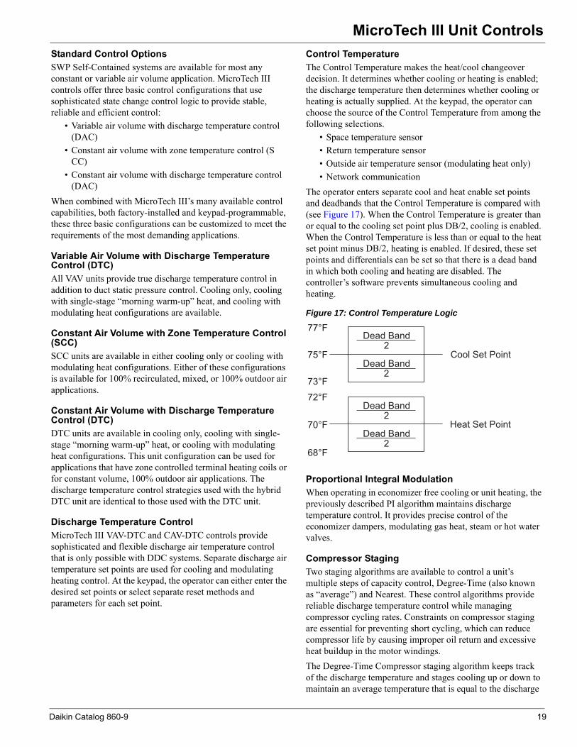
The operator enters separate cool and heat enable set points and deadbands that the Control Temperature is compared with (see Figure 17). When the Control Temperature is greater than or equal to the cooling set point plus DB/2, cooling is enabled. When the Control Temperature is less than or equal to the heat set point minus DB/2, heating is enabled. If desired, these set points and differentials can be set so that there is a dead band in which both cooling and heating are disabled. The controller’s software prevents simultaneous cooling and heating.
Figure 17: Control Temperature Logic
Proportional Integral ModulationWhen operating in economizer free cooling or unit heating, the previously described PI algorithm maintains discharge temperature control. It provides precise control of the economizer dampers, modulating gas heat, steam or hot water valves.
Compressor StagingTwo staging algorithms are available to control a unit’s multiple steps of capacity control, Degree-Time (also known as “average”) and Nearest. These control algorithms provide reliable discharge temperature control while managing compressor cycling rates. Constraints on compressor staging are essential for preventing short cycling, which can reduce compressor life by causing improper oil return and excessive heat buildup in the motor windings.The Degree-Time Compressor staging algorithm keeps track of the discharge temperature and stages cooling up or down to maintain an average temperature that is equal to the discharge
Daikin Catalog 860-9 19
MicroTech III Unit Controls
cooling set point. A stage change can occur only (1) after the keypad adjustable inter-stage timer has expired (five minute default setting) and (2) if the discharge temperature is outside a keypad programmed dead band. After these two conditions have been met, staging occurs as the controller attempts to equalize two running totals: degree-time above set point and degree-time below set point. The result is that the average discharge temperature is maintained at the cooling set point.The Nearest Compressor staging algorithm keeps track of the discharge temperature and stages cooling up or down to maintain the discharge temperature as close as possible to set point. A stage change can occur only (1) after the keypad adjustable inter-stage timer has expired (five minute default setting) and (2) if the control logic calculates that a stage change will result in a discharge temperature closer to set point than the existing condition. The controller logic continually calculates the expected effect of a stage change and uses this information before making a change. A change is made only if it will bring the discharge temperature closer to set point, resulting in a more consistent discharge temperature, reduced compressor cycling and more stable control VAV box control.Supply Air ResetBy automatically varying the discharge air temperature to suit a building’s cooling or heating needs, supply air temperature reset can increase the energy efficiency of VAV and CAV-DTC systems. MicroTech III controllers offer a variety of different reset strategies that can be selected at the keypad. Because they are keypad programmable, reset strategies can be changed or eliminated as desired. Separate strategies can be selected for both cooling and modulating heat. If reset is not desired, a fixed discharge cooling or heating set point can be entered.The following reset methods are available:
• Space temperature• Return temperature• Outdoor air temperature• Supply airflow (VAV, cooling set point only)• External 0–10 VDC or 0–20 mA signal• Network communication
For all temperature reset methods, the minimum and maximum cooling and heating set points are keypad programmable along with the corresponding minimum and maximum space, return or outdoor air temperature parameters. For the supply airflow method, the discharge set point will be reset as the supply fan modulates between 30% adjustable and 100% adjustable. For the external method, the discharge set point will be reset as the voltage or current signal varies over its entire range. For units
in a BAS network, the discharge set points are reset via the communication signal.
Zone Temperature ControlMicroTech III CAV-ZTC controls provide the sophisticated and flexible zone temperature control that is only possible with DDC systems. Zone temperature sensors are available with or without a remote set point adjustment. With the remote adjustment model, the space set point can be set at the keypad or at the zone sensor package. Even if a zone sensor is connected, remote set point adjustment can be enabled or disabled as desired at the keypad.
Control TemperatureThe Control Temperature is the representative zone temperature. When compared with the zone set points, the Control Temperature determines whether the unit supplies heating, cooling, or neither. It also determines the amount of cooling or heating required to satisfy the load. Its source can be selected at the keypad from among the following selections:
• Zone temperature sensor• Return temperature sensor
Because it is the representative zone temperature, the Control Temperature is the primary input to the MicroTech III zone temperature control algorithms. Control Temperature parameters are described below. The controller’s software will prevent cooling and heating from being inadvertently enabled at the same time.
Change and Proportional Integral ModulationWhen economizer “free” cooling or unit heating is required, the two MicroTech III PI loops combine for cascade-type control, providing the tightest possible zone temperature control. By controlling the discharge temperature along with the zone temperature, these functions eliminate temperature variations near the diffusers that could otherwise occur as a result of traditional zone control’s inherent lag effect.
Change: If the Control Temperature is above or below the set point by more than the dead band, the Change PI loop periodically adjusts the cooling or heating discharge air temperature set point either up or down as necessary. The amount of this set point change corresponds to the Control Temperature’s position in the modulation range. The far-ther the Control Temperature is from the set point, the greater the discharge set point change will be. The Change-adjusted discharge cooling and heating set points are limited to ranges defined by keypad programmable maximum and minimum values.PI: Using the Change function’s current discharge set point, the PI function maintains precise discharge temper-
20 Daikin Catalog 860-9

MicroTech III Unit Controls
Compressor StagingCompressor staging is controlled directly by the Control Temperature. When the Control Temperature is warmer than the zone cooling set point, cooling is staged up; when the Control Temperature is cooler than the zone cooling set point, cooling is staged down. However, a stage change can only occur when the Control Temperature is outside the dead band (see Figure 18). Staging is constrained by an inter-stage delay timer (five minute default setting) and minimum and maximum discharge air temperature limits (all keypad programmable). These constraints protect the compressors from short cycling while eliminating temperature variations near the diffusers.Figure 18: Compressorized Logic
Project Ahead AlgorithmBecause the inherent lag effect in zone temperature control applications can cause overshoot during warm-up or cool-down periods, MicroTech III features a “Project Ahead” control algorithm. Project Ahead calculates the rate at which the Control Temperature is changing and reduces the unit’s cooling or heating output as the zone temperature nears its set point, essentially eliminating overshoot.
Duct Static Pressure ControlOn all VAV-DTC units, duct static pressure control is maintained by the PI algorithm, which provides precise control of the supply fan variable speed drive. The keypad programmable set point can be set between 0.20-in. W.C. and 4.00-in. W.C.On larger buildings with multiple floors, multiple trunk runs or large shifts in load due to solar effects (east/west building orientation), an optional second duct static sensor is offered. The MicroTech III controller automatically selects and uses the lower of the two sensed pressures to control fan volume to provide adequate static pressure to the most demanding space at all times.
Operating StatesOperating states define the current overall status of the self-contained system. At the user interface, the operator can display the current operating state and thereby quickly assess the unit’s operating condition.
Alarm Management and ControlMicroTech III unit controllers are capable of sophisticated alarm management and controlled response functions. Each alarm is prioritized, indicated, and responded to with the appropriate action. The active alarm (up to 10 alarms, arranged by alarm priority) and previous alarm (up to 25 alarms, arrange by date/time cleared), each with a time and date stamp, can be displayed at the user interface. Generally speaking, whenever a current alarm is cleared, it is logged as a previous alarm and the oldest previous alarm is removed.
Alarm PriorityThe various alarms that can occur are prioritized according to the severity of the problem. See Table 1. Three alarm categories are used: faults, problems, and warnings.
1 Faults are the highest priority alarms. If a fault condition occurs, the complete unit shuts down until the alarm condition is gone and the fault is manually cleared at the keypad. A fault example is Fan Fail alarm.
2 Problems are the next lower priority to alarms. If a problem occurs, the complete unit does not shut down, but its operation is modified to compensate for the alarm condition. A problem automatically clears when the alarm condition that caused it is gone. Compressor Fail is an example of a problem where only the affected compressor is shut down.
3 Warnings are the lowest priority alarms. No control action is taken when a warning occurs; it is indicated to alert the operator that the alarm condition needs attention. To make sure that they are read, the operator must manually clear all warnings. Dirty Filter indication is an example of a warning.
Generally, a specific alarm condition generates an alarm that falls into only one of these categories. Under different sets of circumstances, however, the freezestat and most of the sensor failure alarm conditions can generate alarms that fall into multiple categories.
Daikin Catalog 860-9 21

MicroTech III Unit Controls
Adjustable Alarm LimitsFour alarm indications have adjustable limits that are used to trigger the alarm. The high return temperature alarm and the high and low supply temperature alarms are adjusted at the user interface. The dirty filter alarm(s) is adjusted at the sensing device.Table 1: MicroTech III Alarm Summary
Alarm Name Fault Problem WarningFreeze X XSmoke X
Temperature Sensor Failure X X
Duct High Limit XHigh Return Temperature X
High Discharge Temperature X
Low Discharge Temperature X
Fan Failure XFan Retry X
Discharge Air Capacity Feedback X
Economizer Stuck X XAuxillary Control Board
Enabled X
Low Airflow XCircuit 1–8
High Pressure X
Circuit 1–8 Low Pressure/Frost X
Compressor 1–8 Motor Protection X
Compressor 1–8 Failure XAirflow Switch (False Airflow) X
Dirty Filter X
22 Daikin Catalog 860-9

Application Considerations
Application ConsiderationsThis section contains basic application and installation guidelines to consider as part of the detailed analysis of any project.
GeneralUnits are intended for use in normal heating, ventilating, and air conditioning applications. Consult your local Daikin sales representative for
• Applications involving operation at high entering con-denser water temperatures; high altitudes; or noncata-loged voltages.
• Applications requiring modified or special control sequences.
• Job-specific unit selections that fall outside of the range of the catalog tables, such as 100% outside air applica-tions.
For proper operation, rig units following instructions in IM 1032. If fire dampers are required, install them in the ductwork according to local codes. Space is not provided for these dampers in the unit.Explicitly follow factory check, test, and start procedures for satisfactory start-up and operation (see IM 1032).Many self-contained system applications take advantage of the significant energy savings provided by the use of economizer operation. When a water economizer system is used, mechanical refrigeration typically is not required below an entering condenser water temperature of 55°F. Standard Daikinself-contained systems are designed to operate with entering water temperatures down to 50°F when a water economizer is used and 55°F with no water economizer. For applications where a water economizer system cannot be used, a modulating head pressure control system is available to permit operation at entering condenser water temperatures below 55°F.
Unit LocationThe floor must be structurally strong enough to support the unit with minimum deflection (see “Unit Weights” starting on page 66). Provide proper structural support to minimize sound and vibration transmission. Consider a concrete floor. Extra design consideration is required when installing on a wooden structure. Install units level from front-to-back and over their length.Locate unit fresh air intakes away from building flue stacks, exhaust ventilators, and areas containing automotive or other exhaust to prevent the possible introduction of contaminated air to the system. Consult code requirements for minimum fresh air volumes.Allow sufficient space around the unit for service and maintenance clearance. Refer to Figure 19 for recommended service/maintenance clearances and “Recommended Clearances” on page 61. Locate equipment room access doors in a manner that can assist in service access if needed (e.g., coil removal). Contact your local Daikin sales representative if reduced service/maintenance clearances are required.Where code considerations such as the NEC require extended clearances, they take precedence over minimum service/ maintenance clearances.
Figure 19: Recommended Service and Maintainance Clearances
Evaporator Coil
Motor
Con
trol
Pan
el
Airflow24"
See Note
18"or
24"
36"
42"
Rear Side
Front Side
OppositeAccess
SideAccess
Side
NOTE: If water and condenser drains are on the motor side, 24" is required.
Daikin Catalog 860-9 23
Application Considerations
Acoustical ConsiderationsGood acoustical design is a critical part of any successful installation and should start at the earliest stages in the design process. Each of the four common sound paths must be addressed. They are:• Radiated sound through the casing of the unit• Structure-borne vibration• Airborne sound through the supply air duct• Airborne sound through the return air duct
Basic guidelines for good acoustical performance include:1 Always provide proper structural support under the unit.2 Provide adequate mass in the floor structure, especially
when located over an occupied space where good acoustics are essential.
3 Seal all supply and return air duct penetrations once the duct is installed.
4 Don’t overlook the return air path. Always include some duct work (acoustically-lined drop down elbow) at the return inlet.
5 Minimize system static pressure losses to reduce fan sound generation.
6 Select the appropriate unit/fan for the application. Select fans as close as possible to their peak static efficiency. To assist you, peak static efficiency is identified by the first system curve to the right of the shaded “Do not select” region on each fan curve. See page 54 through page 60.
7 Design duct systems to minimize turbulence.8 Account for low frequency duct breakout noise in system
design. Route the first 20' of rectangular duct over nonsensitive areas and avoid large duct aspect ratios. Consider round or oval duct to reduce breakout.
Equipment RoomLocate the equipment room away from sound sensitive areas. Whenever possible, isolate the equipment room from these areas by locating restrooms, utility rooms, stairwells, hallways, elevators, etc. around its perimeter. This allows not only isolation from radiated sound but provides the capability to route ductwork over less sensitive areas.Acoustically seal the equipment room with a high quality, flexible material to prevent air and noise from escaping. Even a small leak compromises the acoustic performance of the installation. Design the equipment room door to seal tightly on a perimeter gasket.
Equipment room wall construction should be concrete block or offset, double stud. The decision depends on the critical nature of the application. If offset, use double stud construction. Line the cavity with glass fiber insulation and use a double layer of wallboard on each side of the wall.
DuctworkFan noise travels through the ductwork to occupied spaces; it likely is the most challenging to control. Careful duct design and routing practice is required. The ASHRAE Applications Handbook discusses sound attenuation relevant to self-contained system applications. Advances in acoustical science allow for designing sound levels in a given space if equipment sound power data is available. Contact your local Daikin sales representative for sound power data for your specific application.
Return DuctThe return duct is often overlooked. Duct return air directly to the unit or into the equipment room. If ducted to the equipment room, install an elbow within the equipment room. Running a return air drop near the floor of the room provides added attenuation. Extend a length of lined ductwork from the equipment room to a length of 15 feet. The maximum recommended return air duct velocity is 1000 feet per minute.
Supply DuctExtend a lined section of supply air duct at least 15 feet from the equipment room. Using round duct significantly reduces low frequency sound near the equipment room. If rectangular duct is used, keep the aspect ratio of the duct as small as possible. The large flat surfaces associated with large aspect ratios transmit sound to the space and increase the potential for duct generated noise such as oil canning. The maximum recommended supply air duct velocity is 2000 feet per minute.Factory-designed and factory-built acoustic discharge plenums are available with multiple outlets to minimize difficult transitions, tight radius duct connections, and the sound compromises they can cause. Multiple factory-fabricated outlet opening sizes are available as well as multiple openings in a single plenum.
Duct ProtectionAn adjustable duct high limit switch is standard equipment on all SWP systems with VAV controls. This is of particular importance when using fast-acting, normally closed boxes. The switch is field adjustable; set it to meet the specific rating of the system ductwork.
24 Daikin Catalog 860-9

Application Considerations
Vibration IsolationMake duct connections to the unit or to the acoustic discharge plenum with a flexible connection. Though flexible piping and electrical connections are not required, pay attention to these areas to avoid vibration transmission from outside sources to the SWP unit.Condenser Water PipingAlways follow good industry practice in the water piping system design. Attention to water treatment and proper strainer application are always necessary. All SWP systems feature mechanically cleanable condensers and optional waterside economizer coils. To allow periodic cleaning of the condensers and economizer coils, provide isolation valves. Condensers, economizer coils and hot water coils are provided with vent and drain connections.Always review for possible requirements for condenser piping insulation, especially if cold entering condenser water conditions (<55°F) will be experienced.
Figure 20: Condensers
Head Pressure ControlIf cold entering condenser water conditions (<55°F) will be experienced, use a waterside economizer or a condenser head pressure control valve. A two-way, head pressure activated control valve is available factory installed for these applications. The head pressure control allows entering condenser water temperatures as low as 40°F. A head pressure control valve is not required when the SWP unit is applied with a factory waterside economizer package.
Figure 21: Head Pressure Control Valves
Variable Air VolumeDaikin SWP units offer variable frequency drives for fan speed control. VFDs offer reliable operation over a wide range of airflow, with variable frequency drives offering advantages in sound and energy performance. In addition, Daikin offers the ability to sense duct static pressure in multiple locations, enhancing control accuracy and helping minimize energy use.
Two-Way Head Pressure Control Valve
Daikin Catalog 860-9 25

Application Considerations
Variable Frequency DrivesVariable frequency drives provide the most efficient means of variable volume control by taking advantage of the fan law relation between fan speed (rpm) and fan brake horsepower (bhp). Also, since airflow reduction is accomplished by changing fan speed, the noise penalties often associated with mechanical control devices, e.g., inlet vanes, are not introduced. The following equation illustrates how fan bhp varies as the cube of the change in fan speed:In an ideal system, at 50% fan speed, brake horsepower is reduced to 12.5% of that at full speed.Variable frequency control varies the speed of the fan by adjusting the frequency and voltage to the motor. Keeping a constant volts/frequency ratio (constant magnetic flux) to the motor allows the motor to run at its peak efficiency over a wide range of speeds and resulting fan airflow volumes.
Figure 22: Variable Frequency Drive
Duct Static Pressure Sensor PlacementStatic pressure should be sensed near the end of the main duct trunk(s). Adjust the MicroTech III static pressure control so that at full airflow all of the terminals receive the minimum static pressure required plus any downstream resistance. Control is to the lowest static pressure set point that satisfies airflow requirements. Lower static pressure set points reduce fan brake horsepower requirements and fan sound generation.Locate the static pressure sensor tap in the ductwork in an area free from turbulence effects and at least 10 duct diameters downstream and several duct diameters upstream from any major interference, including branch takeoffs. The SWP MicroTech III control system can receive a second duct static pressure sensor in installations having multiple duct trunks or significantly varying zones. The control logic maintains static pressure at both sensors.
Zone Sensor PlacementPlacement of the zone temperature sensor is extremely important to provide proper and economical operation of the heating and cooling system. Generally, Daikin recommends locating the space sensor on an inside wall (3 to 5 feet from an outside wall) in a space having a floor area of at least 400 square feet. Do not locate the sensor below the outlet of a supply air diffuser, in the direct rays of the sun, on a wall adjacent to an unheated or abnormally warm room (boiler or incinerator room), or near any heat producing equipment. Where zone sensor placement is a problem, all SWP zone control systems have, as standard, the capability to use the return air sensor for heating and cooling control.
FiltrationRoutinely replace filters to minimize filter loading. As filters get dirty, the filter pressure drop increases, affecting system airflow and energy requirements. The effect of filter loading is the most critical when using high efficiency filters.When making a fan selection, include a pressure drop component in the system total static pressure to account for dirty filters. Use a value midway between clean and dirty filter ratings. If a minimum airflow is critical, make the fan selection using the higher, dirty filter pressure drop value. For VAV systems, consider setting the fan control device so part of its modulation range can be used to maintain airflow as filters become dirty. Following these recommendations should limit airflow fluctuation as the filters load.
hp2 = hp1
density2
density1
rpm2
rpm1
3
26 Daikin Catalog 860-9
Application Considerations
System Operating LimitsSWP units can be applied in a wide range of system needs. High cfm/ton or high/low discharge temperature applications are available. However, for proper system operation, some application limits do apply.AirflowMaximum cfm limits based on coil face velocity are listed in the Physical Data tables starting on page 31.Separate minimum design cfm limits by unit size are listed in the physical data table for constant and variable air volume applications. Limit fan modulation to 40% of the minimum design cfm limit. Minimum airflow conditions are dependent on fan selection criteria also. Contact your Daikin sales representative to answer questions on minimum airflow capability or for conditions not shown in this catalog.VAV box minimum airflow settings should correspond with the minimum VAV fan operating point. All units are provided with multigroove, fixed pitch sheaves. During system air balance, alternate fixed pitch sheaves may be needed to match final system requirements. Alternate sheaves are available from Daikin.
Fan HeatSensible heat gain from the fan, fan motor, and drives occurs in all fan systems; consider its effect during equipment selection. It is an added load in cooling and an added source when in heating. The majority of the heat gain occurs through the fan itself, as the air elevates from the low-pressure side to the high-pressure side of the fan. Moving the motor out of the air stream has a negligible effect on overall fan heat gain. A unit with higher fan power requirements/higher fan heat has less net cooling capability and may not have enough left to satisfy system loads.As a rule, typical supply fan heat gain is 3°F. However, fan heat gain can be calculated quickly once the fan is selected and the fan brake horsepower is determined. Using Figure 23, select your fan brake horsepower on the horizontal axis and move up vertically until you intersect with the heat gain curve. Then move horizontally to find the fan heat gain in MBh.
Figure 23: Fan and Motor Heat Gain
A draw-through unit has the fan located after the DX cooling coil. In this arrangement, fan heat is applied as reheat to the cold, conditioned air coming off of the coil. This arrangement has a lower sensible heat ratio and higher dehumidification capability than a blow-through coil arrangement. The discharge temperature available to the supply duct is always the sum of the coil leaving air temperature plus the fan temperature rise. Consider this when selecting the supply air volume required to satisfy space requirements.
Condenser Water FlowSystem capacity tables provide selections for a condenser flow rate of 3 gpm/ton. For a given entering condenser water temperature, 3 gpm/ton provides maximum unit performance. Reducing condenser water flow rates to 2.5 or 2 gpm/ton can significantly reduce pumping energy costs and reduce piping costs. Compare and evaluate the reduction in pumping energy to the change in unit performance. Use the SWP capacity tables (Table 8, page 36) for condenser flow rates from 2 to 3 gpm/ton, using the appropriate leaving condenser water temperature column (interpolation is allowed). The minimum condenser flow rate is 2 gpm/ton.
Fan temperature rise =(fan heat (MBh))(1.085 × fan cfm)
52°F + 3°Fleavingcoiltemperature
fantemperaturerise
= 55°Fdischargeairtemperature
Example:
Daikin Catalog 860-9 27
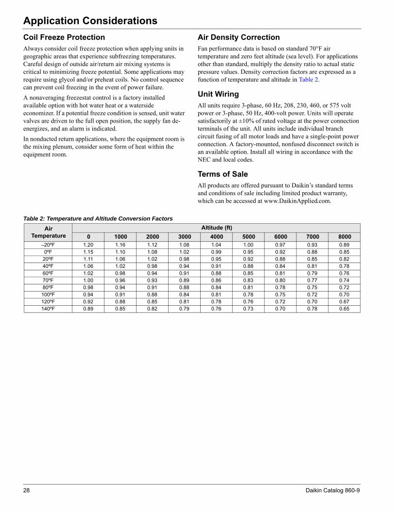
Application Considerations
Coil Freeze ProtectionAlways consider coil freeze protection when applying units in geographic areas that experience subfreezing temperatures. Careful design of outside air/return air mixing systems is critical to minimizing freeze potential. Some applications may require using glycol and/or preheat coils. No control sequence can prevent coil freezing in the event of power failure.A nonaveraging freezestat control is a factory installed available option with hot water heat or a waterside economizer. If a potential freeze condition is sensed, unit water valves are driven to the full open position, the supply fan de-energizes, and an alarm is indicated.In nonducted return applications, where the equipment room is the mixing plenum, consider some form of heat within the equipment room.Air Density CorrectionFan performance data is based on standard 70°F air temperature and zero feet altitude (sea level). For applications other than standard, multiply the density ratio to actual static pressure values. Density correction factors are expressed as a function of temperature and altitude in Table 2.
Unit WiringAll units require 3-phase, 60 Hz, 208, 230, 460, or 575 volt power or 3-phase, 50 Hz, 400-volt power. Units will operate satisfactorily at ±10% of rated voltage at the power connection terminals of the unit. All units include individual branch circuit fusing of all motor loads and have a single-point power connection. A factory-mounted, nonfused disconnect switch is an available option. Install all wiring in accordance with the NEC and local codes.
Terms of SaleAll products are offered pursuant to Daikin’s standard terms and conditions of sale including limited product warranty, which can be accessed at www.DaikinApplied.com.
Table 2: Temperature and Altitude Conversion Factors
Air Temperature
Altitude (ft)0 1000 2000 3000 4000 5000 6000 7000 8000
–20ºF 1.20 1.16 1.12 1.08 1.04 1.00 0.97 0.93 0.890ºF 1.15 1.10 1.08 1.02 0.99 0.95 0.92 0.88 0.85
20ºF 1.11 1.06 1.02 0.98 0.95 0.92 0.88 0.85 0.8240ºF 1.06 1.02 0.98 0.94 0.91 0.88 0.84 0.81 0.7860ºF 1.02 0.98 0.94 0.91 0.88 0.85 0.81 0.79 0.7670ºF 1.00 0.96 0.93 0.89 0.86 0.83 0.80 0.77 0.7480ºF 0.98 0.94 0.91 0.88 0.84 0.81 0.78 0.75 0.72
100ºF 0.94 0.91 0.88 0.84 0.81 0.78 0.75 0.72 0.70120ºF 0.92 0.88 0.85 0.81 0.78 0.76 0.72 0.70 0.67140ºF 0.89 0.85 0.82 0.79 0.76 0.73 0.70 0.78 0.65
28 Daikin Catalog 860-9

Selection Procedure
Selection ProcedureAchieving the optimal performance of any system requires both accurate system design and proper equipment selection. Factors that control unit selection include applicable codes, ventilation and filtration requirements, heating and cooling loads, acceptable temperature differentials, and installation limitations. Daikin SWP units offer a wide selection of component options providing the capability to meet diverse application needs. The Daikin SelectTools™ software selection program allows your local Daikin sales representative to provide you with a fast, accurate, and complete selection of Daikin SWP units. Unit selection also can be accomplished through reference to physical, performance, dimensional and unit weight data included in this catalog. Due to the variety of cooling system options available, only a sampling of cooling capacity data is presented here. To properly select equipment, follow these steps:
1 Select the unit size and compressor combination. 2 Select the heating system. 3 Select the fan and motor.
The following example illustrates the catalog selection procedure.
Selection Example: Scheduled design requirements:
Supply air volume . . . . . . . . . . . . . . . . . . . . . . . . . 21,000 cfm Maximum face velocity . . . . . . . . . . . . . . .550 fpm is chosen* Supply fan external . . . . . . . . . . . . . . . . . . . . . . . SP 2.00" w.g. Altitude . . . . . . . . . . . . . . . . . . . . . . . . . . . . . . . . . . . . sea level Variable air volume system with fan speed control Hot water heat Water economizer system 4" 30% (MERV8) pleated filters 460 V/60 Hz/3 Ph Double wall construction R-410A refrigerant Premium efficiency motor *600 fpm is the design limit per page with tables starting on page 31
Summer design:
DX coil mixed air dry bulb . . . . . . . . . . . . . . . . . . . . . . . 80°F DX coil mixed air wet bulb . . . . . . . . . . . . . . . . . . . . . . . 67°F Sensible load . . . . . . . . . . . . . . . . . . . . . . . . . . 575,000 Btu/hr Total load . . . . . . . . . . . . . . . . . . . . . . . . . . . . . 750,000 Btu/hr Supply fan sensible heat . . . . . . . . . . . . . . . . . . . . . . . . 3°F rise Entering condenser water . . . . . . . . . . . . . . . . . . . . . . . . . 85°F Leaving condenser water . . . . . . . . . . . . . . . . . . . . . . . . . 95°F Minimum condenser water . . . . . . . . . . . . . . . . . . . . . . . . 55°F
Winter design:
Return air temperature . . . . . . . . . . . . . . . . . . . . . . . . . . . 60°F Space heating load . . . . . . . . . . . . . . . . . . . . . . . . . 1,000-MBh Entering hot water temperature . . . . . . . . . . . . . . . . . . . 180°F
Step 1: Unit Size Selection Unit size is based on coil face area and cooling capacity requirements. Use supply air capacity and maximum face velocity constraints as a guide for selecting coil dimensions and cabinet size. Based on the given data, the appropriate coil face area is determined as follows:
Minimum face area = cfm/maximum face velocity = 21,000 cfm/550 fpm = 38.2 square feet
Note: Unit data is based on standard air conditions of 70°F at sea level. See “Application Considerations” on page 23 for temperature/altitude conversion factors for nonstandard conditions.
Referring to the “Physical Data” tables starting on page 31, the 40.8 square foot coil of the SWP 062HSM satisfies the requirements.
Step 2: Unit DX Cooling Selection Since the design cfm is less than the nominal value in the DX Cooling Capacity Data table, adjust the capacities per tables on starting on page 36.
cfm correction factor = design cfm/nominal cfm = 21,000 / 21,500 = 97.7%
Total heat correction multiplier = 0.995 Sensible heat correction multiplier = 0.987 Using the “Performance Data” starting on page 36, the unit selection is a SWP 062 HS with (2) 13 hp and (2) 15 hp compressors. Unit performance from the table equals 806.0 TMBh / 587.0 SMBh at 190 gpm. Adjusting for the specified cfm yields: Total capacity = 806.0 MBh ×0.995 = 800.9 MBh
Sensible capacity = 587.0 MBh × 0.987 = 579.2 MBh
Coil LAT = 80ºF – 579.0 MBh/(1.085 × 21,000 cfm) = 54.7°F1,000
Condenser flow rate = 196 gpm × 0.995 = 195 gpm
Step 3: Economizer Capacity Selection Determine waterside economizer capacity by referring to the appropriate table. See “Waterside Economizer Capacity” on page 44 for 40.8 sq.ft. coil. Use entering air of 80/67°F and entering water of 55°F at 185 gpm. Interpolating for the required gpm, economizer performance equals 497.8 TMBh / 473.0 SMBh at the unit’s nominal cfm. See tables starting on page 45, “Waterside Economizer Capacity Correction Factors,” to find performance at the specified cfm.
Total capacity = 415.2 MBh × 1.12 = 465.0 MBh
Sensible capacity = 363.8 MBh × 1.19 = 432.9 MBh
Daikin Catalog 860-9 29

Selection Procedure
Step 4: Heating Selection Determine hot water capacity from the tables starting on page 45. After interpolating for the specified cfm, Table 16 indicates a capacity of 1,002.0 MBh.Step 5: Fan/Motor Selection Fan/motor selection is based on unit total static pressure and design airflow. Total static pressure includes the internal air pressure drops of unit components and external air pressure drops of supply and return air duct systems. See “Component Pressure Drops” starting on page 46 for internal pressure drops of unit components. Values in the table may be interpolated for the specified cfm. Internal pressure drops:
DX coil (wet surface) . . . . . . . . . . . . . . . . . . . . . .0.80" w.g. Economizer coil (dry surface) . . . . . . . . . . . . . . .0.49" w.g. Hot water coil . . . . . . . . . . . . . . . . . . . . . . . . . . . .0.52" w.g. 4", 30% efficient filters . . . . . . . . . . . . . . . . . . . . .0.29" w.g. Total internal pressure drop . . . . . . . . . . . . . . . . . .2.1" w.g.
External pressure drop: Supply + return duct . . . . . . . . . . . . . . . . . . . . . . .2.00" w.g.
Total static pressure = internal drops + external drops = 2.1" + 2.00" = 4.10" w.g.
Entering the fan curve for the SWP 062 HSM at 21,000 cfm and 4.10" w.g. yields 18.35 required fan brake horsepower. A 20 horsepower motor can be selected with a 33" diameter fan.
Step 6: Calculating Unit Weight Referring to the tables starting on page 66. For an SWP 062 HS: Unit weight: SWP basic unit . . . . . . . . . . . . . . . . . . . . . . .6179
+ 30% filters . . . . . . . . . . . . . . . . . . . . . . . . .22+ 6-row evaporator coil . . . . . . . . . . . . . . . .668 + economizer coil . . . . . . . . . . . . . . . . . . . .557+ water (econ. coil). . . . . . . . . . . . . . . . . . . .250+ hot water coil . . . . . . . . . . . . . . . . . . . . . .200+ water (HW coil). . . . . . . . . . . . . . . . . . . . . .49 + SAF motor . . . . . . . . . . . . . . . . . . . . . . . . .235+ VFD . . . . . . . . . . . . . . . . . . . . . . . . . . . . . .35+ SAF assembly . . . . . . . . . . . . . . . . . . . . . .592
= 8,752 lbs.
Step 7: Supply Power Wiring Supply power wire sizing for a unit is based on the circuit with the highest amperage draw. All electrical equipment is wired to a central control panel for either single or optional dual power connections. Refer to “Electrical Data” on page 65 for FLA and RLA ratings. Determine Minimum Circuit Ampacity (MCA) as follows:
MCA = [1.25 × RLA or FLA of largest motor] + [1.00 × RLA or FLA of all other loads] + [2 amps (controls)]
RLA/FLA (2) 13 horsepower compressors . . . . . . . . . . . . 18.3 amps each (2) 15 horsepower compressors . . . . . . . . . . . . 18.5 amps each 25 horsepower premium efficiency
supply fan motor . . . . . . . . . . . . . . . . . . . . . . . . . 24.5 amps MCA = [1.25×24.5 amps] + [18.3+18.3+18.5+18.5] + [2] = 106.2 amps
Note: If a unit is selected with non-concurrent electric heat, calculate the MCA for both the heating mode and the cooling mode and the larger value used.
30 Daikin Catalog 860-9

Physical Data
Physical DataTable 3: SWP 012 through SWP 033 Physical Data
Data Small Cabinet023 028 033
CompressorQuantity 2Size (HP) 6, 15 6, 15 10, 15 10, 15 15 (2) 15 (2)Number of refrigeration circuits 2Evaporator coilCoil size Standard Large Standard Large Standard LargeFace area (ft2) 17.2 25.2 17.2 25.2 17.2 25.2Number of rows 5FPI 12PerformanceTotal capacity1 (MBH) 312 334 357 386 411 448Unit EER2 14.3 14.7 13.8 14.4 13.3 14.0Pre-heating coilMinimum hot water coil face area (ft2) 19.8Available rows 1 through 12Minimum steam coil face area (ft2) 19.8Available rows 1 through 4FPI 6 through 14Waterside economizer coilFace area (ft2) 17.2 25.2 17.2 25.2 17.2 25.2Rows 4FPI 12Maximum working pressure (PSIG) 300 standard, 450 optionalFace loaded filters(Quantity) Size (9) 24×242" filter options 30% (MERV7), 75% (MERV13)4" filter options 30% (MERV8), 75% (MERV11), 85% (MERV14)Pre-filter options 2"-30% with 4"-65%, 2"-30% with 4"-75%, 2"-30% with 4"-85%Evaporator fan3
Quantity 1Available diameter (Inches) 12, 15, 18, 20, 22, 24Maximum motor size (HP) 20CAV minimum design (CFM)4 3440 5040 3440 5040 3440 5040VAV minimum design (CFM)4 6880 10080 6880 10080 6880 10080Maximum design (CFM)4 10320 15120 10320 15120 10320 15120Electric heatNominal output (kW) 34Control sequence 2-stageCondenserMaximum working pressure (PSIG) 300 standard, 450 optionalMechanical cooling minimum EWT (ºF) 55Minimum flow rate (GPM) 52 56 59 64 69 75Maximum flow rate (GPM) 78 84 89 96 103 112Note: 1. Based on AHRI 340/360 standard rating conditions, 80/67ºF to the coil, 85/95ºF condenser water.
2. Based on AHRI 340/360 standard rating conditions.3. Standard fan TSP limit is 6.0 inches of water. Consult your local Daikin sales representative for applications beyond this range.4. Minimum design airflow calculated for CAV at 200 fpm, VAV at 400 fpm and a maximum design airflow calculated at 600fpm.
Daikin Catalog 860-9 31

Physical Data
Table 4: SWP 039 through SWP 050 Physical Data
Data Small Tall Cabinet039 044 050
CompressorQuantity 3Size (HP) 10(2), 15 10(2), 15 10, 15(2) 10(2), 15 15(3)Number of refrigeration circuits 3Evaporator coilCoil size Standard Large Standard Large LargeFace area (ft2) 25.2 29.8 25.2 29.8 29.8Number of rows 5FPI 12PerformanceTotal capacity1 (MBH) 516 535 589 645 645Unit EER2 14.4 14.6 14.2 14.4 13.6Pre-heating coilMinimum hot water coil face area (ft2) 19.8Available rows 1 through 12Minimum steam coil face area (ft2) 19.8Available rows 1 through 4FPI 6 through 14Waterside economizer coilFace area (ft2) 25.2 29.8 25.2 29.8 29.8Rows 4FPI 12Maximum working pressure (PSIG) 300 standard, 450 optionalFace loaded filters(Quantity) Size (9) 24×242" filter options 30% (MERV7), 75% (MERV13)4" filter options 30% (MERV8), 75% (MERV11), 85% (MERV14)Pre-filter options 2"-30% with 4"-65%, 2"-30% with 4"-75%, 2"-30% with 4"-85%Evaporator fan3
Quantity 1Available diameter (Inches) 18, 20, 22, 24, 27Maximum motor size (HP) 20CAV minimum design (CFM)4 5040 5960 5040 5960 5960VAV minimum design (CFM)4 10080 11920 10080 11920 11920Maximum design (CFM)4 15120 17880 15120 17880 17880Electric heatNominal output (kW) 34Control sequence 2-stageCondenserMaximum working pressure (PSIG) 300 standard, 450 optionalMechanical cooling minimum EWT (ºF) 55Minimum flow rate (GPM) 86 89 98 107 107Maximum flow rate (GPM) 129 134 147 161 161Note: 1. Based on AHRI 340/360 standard rating conditions, 80/67ºF to the coil, 85/95ºF condenser water.
2. Based on AHRI 340/360 standard rating conditions.3. Standard fan TSP limit is 6.0 inches of water. Consult your local Daikin sales representative forXXapplications beyond this range.4. Minimum design airflow calculated for CAV at 200 fpm, VAV at 400 fpm and a maximum design airflow XXcalculated at 600fpm.
32 Daikin Catalog 860-9

Physical Data
Table 5: SWP 044 through SWP 055 Physical Data
Data Medium Cabinet044 050 056 062 065
CompressorQuantity 3 4Size (HP) 10(2), 15 (3)15 (4)13 13(2), 15(2) 15(4)Number of refrigeration circuits 3 4Evaporator coilCoil size Standard Standard Large Standard Large Standard Large Standard LargeFace area (ft2) 40.8 40.8 45.8 40.8 45.8 40.8 45.8 40.8 45.8Number of rows 5FPI 12PerformanceTotal capacity1 (MBH) 624 690 705 774 792 816 834 865 884Unit EER2 14.5 14.2 14.3 14.8 14.9 14.2 14.3 13.8 14.0Pre-heating coilMinimum hot water coil face area (ft2) 32.25Available rows 1 through 12Minimum steam coil face area (ft2) 32.25Available rows 1 through 4FPI 6 through 14Waterside economizer coilFace area (ft2) 40.8 40.8 45.8 40.8 45.8 40.8 45.8 40.8 45.8Rows 4FPI 12Maximum working pressure (PSIG) 300 standard, 450 optionalFace loaded filters(Quantity) Size (4) 12×24 and (12) 24×242" filter options 30% (MERV7), 75% (MERV13)4" filter options 30% (MERV8), 75% (MERV11), 85% (MERV14)Pre-filter options 2"-30% with 4"-65%, 2"-30% with 4"-75%, 2"-30% with 4"-85%Evaporator fan3
Quantity 1Available diameter (Inches) 18, 20, 22, 24, 27, 30, 33, 37Maximum motor size (HP) 40CAV minimum design (CFM)4 8160 8160 9160 8160 9160 8160 9160 8160 9160VAV minimum design (CFM)4 16320 16320 18320 16320 18320 16320 18320 16320 18320Maximum design (CFM)4 24480 24480 27480 24480 27480 24480 27480 24480 27480Electric heatNominal output (kW) 34, 685
Control sequence 2-stageCondenserMaximum working pressure (PSIG) 300 standard, 450 optionalMechanical cooling minimum EWT (ºF) 55Minimum flow rate (GPM) 104 115 118 129 132 136 139 144 147Maximum flow rate (GPM) 156 173 176 194 198 204 209 216 221Note: 1. Based on AHRI 340/360 standard rating conditions, 80/67ºF to the coil, 85/95ºF condenser water.
2. Based on AHRI 340/360 standard rating conditions.3. Standard fan TSP limit is 6.0 inches of water. Consult your local Daikin sales representative for applications beyond this range.4. Minimum design airflow calculated for CAV at 200 fpm, VAV at 400 fpm and a maximum design airflow calculated at 600fpm.5. Available for 460 volt and 575 volt units only
Daikin Catalog 860-9 33

Physical Data
Table 6: SWP 062 through SWP 088 Physical Data
Data Large Cabinet062 073 080 088
CompressorQuantity 4 6Size (HP) 13(2), 15(2) 10(4), 13(2) 10(2), 13(4) 13(6)Number of refrigeration circuits 4 6Evaporator coilCoil size StandardFace area (ft2) 52.5Number of rows 5 6FPI 12PerformanceTotal capacity1 (MBH) 866 1021 1093 1164Unit EER2 14.6 14.1 14.6 14.4Pre-heating coilMinimum hot water coil face area (ft2) 36, 67Available rows 1 through 12Minimum steam coil face area (ft2) 36, 67Available rows 1 through 4FPI 6 through 14Waterside economizer coilFace area (ft2) 52.5Rows 4FPI 12Maximum working pressure (PSIG) 300 standard, 450 optionalFace loaded filters(Quantity) Size (5) 12×24 and (15) 24×242" filter options 30% (MERV7), 75% (MERV13)4" filter options 30% (MERV8), 75% (MERV11), 85% (MERV14)Pre-filter options 2"-30% with 4"-65%, 2"-30% with 4"-75%, 2"-30% with 4"-85%Evaporator fan3
Quantity 1Available diameter (Inches) 22, 24, 27, 30, 33, 37Maximum motor size (HP) 50CAV minimum design (CFM)4 10500VAV minimum design (CFM)4 21000Maximum design (CFM)4 31500Electric heatNominal output (kW) 68Control sequence 2-stageCondenserMaximum working pressure (PSIG) 300 standard, 450 optionalMechanical cooling minimum EWT (ºF) 55Minimum flow rate (GPM) 144 170 182 194Maximum flow rate (GPM) 217 255 573 291Note: 1. Based on AHRI 340/360 standard rating conditions, 80/67ºF to the coil, 85/95ºF condenser water.
2. Based on AHRI 340/360 standard rating conditions.3. Standard fan TSP limit is 6.0 inches of water. Consult your local Daikin sales representative for XXapplications beyond this range.4. Minimum design airflow calculated for CAV at 200 fpm, VAV at 400 fpm and a maximum design airflow XXcalculated at 600fpm.
34 Daikin Catalog 860-9

Physical Data
Table 7: SWP 065 through SWP 130 Physical Data
Data Large Tall Cabinet065 073 080 088 099 105 120 130
CompressorQuantity 4 6 8
Size (HP) 15(4) 10(4), 13(2)
10(2), 13(4) 13(6) 15(6) 13(8) 13(4), 15(4) 15(8)
Number of refrigeration circuits 4 6 8Evaporator coilCoil size Std Std Lg Std Lg Std Lg Std LgFace area (ft2) 60.9 60.9 71.3 60.9 71.3 60.9 71.3 60.9 71.3Number of rows 6FPI 12PerformanceTotal capacity1 (MBH) 946 1052 1128 1202 1343 1381 1451 1527 1526 1606 1621 1701Unit EER2 14.5 15.1 14.9 14.7 13.7 14.0 13.6 14.3 13.2 13.7 12.8 13.3Pre-heating coilMinimum hot water coil face area (ft2) 45.83Available rows 1 through 12Minimum steam coil face area (ft2) 45.83Available rows 1 through 4FPI 6 through 14Waterside economizer coilFace area (ft2) 60.9 60.9 71.3 60.9 71.3 60.9 71.3 60.9 71.3Rows 4FPI 12Maximum working pressure (PSIG) 300 standard, 450 optionalFace loaded filters(Quantity) Size (20) 24×242" filter options 30% (MERV7), 75% (MERV13)4" filter options 30% (MERV8), 75% (MERV11), 85% (MERV14)Pre-filter options 2"-30% with 4"-65%, 2"-30% with 4"-75%, 2"-30% with 4"-85%Evaporator fan3
Quantity 1Available diameter (Inches) 24, 27, 30, 33, 37, 40, 44Maximum motor size (HP) 50CAV minimum design (CFM)4 12180 12180 14260 12180 14260 12180 14260 12180 14260VAV minimum design (CFM)4 24360 24360 28520 24360 28520 24360 28520 24360 28520Maximum design (CFM)4 36540 36540 42780 36540 42780 36540 42780 36540 42780Electric heatNominal output (kW) 68Control sequence 2-stageCondenserMaximum working pressure (PSIG) 300 standard, 450 optionalMechanical cooling minimum EWT (ºF) 55Minimum flow rate (GPM) 158 175 188 200 224 230 242 254 254 268 270 284Maximum flow rate (GPM) 237 263 282 300 336 345 363 382 382 402 405 425Note: 1. Based on AHRI 340/360 standard rating conditions, 80/67ºF to the coil, 85/95ºF condenser water.
2. Based on AHRI 340/360 standard rating conditions.3. Standard fan TSP limit is 6.0 inches of water. Consult your local Daikin sales representative for applications beyond this range.4. Minimum design airflow calculated for CAV at 200 fpm, VAV at 400 fpm and a maximum design airflow calculated at 600fpm.
Daikin Catalog 860-9 35
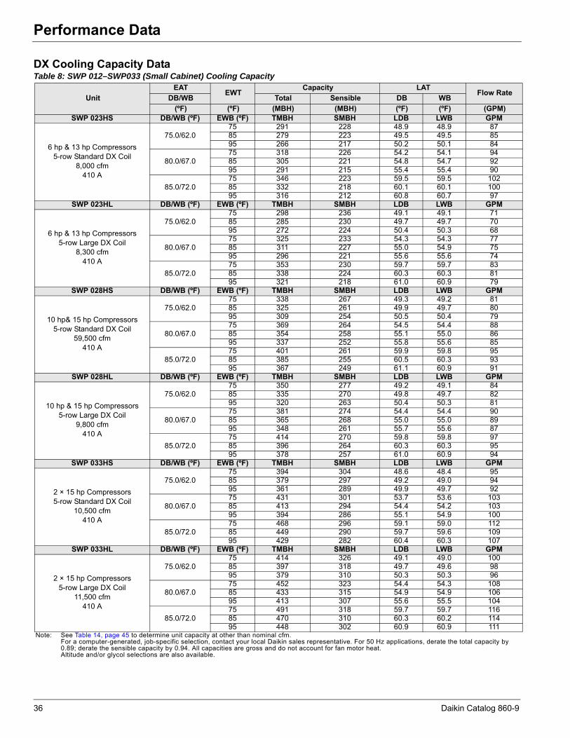
Performance Data
Performance DataDX Cooling Capacity DataTable 8: SWP 012–SWP033 (Small Cabinet) Cooling Capacity
UnitEAT
EWTCapacity LAT
Flow RateDB/WB Total Sensible DB WB
(ºF) (ºF) (MBH) (MBH) (ºF) (ºF) (GPM)SWP 023HS DB/WB (ºF) EWB (ºF) TMBH SMBH LDB LWB GPM
6 hp & 13 hp Compressors5-row Standard DX Coil
8,000 cfm410 A
75.0/62.075 291 228 48.9 48.9 8785 279 223 49.5 49.5 8595 266 217 50.2 50.1 84
80.0/67.075 318 226 54.2 54.1 9485 305 221 54.8 54.7 9295 291 215 55.4 55.4 90
85.0/72.075 346 223 59.5 59.5 10285 332 218 60.1 60.1 10095 316 212 60.8 60.7 97
SWP 023HL DB/WB (ºF) EWB (ºF) TMBH SMBH LDB LWB GPM
6 hp & 13 hp Compressors5-row Large DX Coil
8,300 cfm410 A
75.0/62.075 298 236 49.1 49.1 7185 285 230 49.7 49.7 7095 272 224 50.4 50.3 68
80.0/67.075 325 233 54.3 54.3 7785 311 227 55.0 54.9 7595 296 221 55.6 55.6 74
85.0/72.075 353 230 59.7 59.7 8385 338 224 60.3 60.3 8195 321 218 61.0 60.9 79
SWP 028HS DB/WB (ºF) EWB (ºF) TMBH SMBH LDB LWB GPM
10 hp& 15 hp Compressors5-row Standard DX Coil
59,500 cfm410 A
75.0/62.075 338 267 49.3 49.2 8185 325 261 49.9 49.7 8095 309 254 50.5 50.4 79
80.0/67.075 369 264 54.5 54.4 8885 354 258 55.1 55.0 8695 337 252 55.8 55.6 85
85.0/72.075 401 261 59.9 59.8 9585 385 255 60.5 60.3 9395 367 249 61.1 60.9 91
SWP 028HL DB/WB (ºF) EWB (ºF) TMBH SMBH LDB LWB GPM
10 hp & 15 hp Compressors5-row Large DX Coil
9,800 cfm410 A
75.0/62.075 350 277 49.2 49.1 8485 335 270 49.8 49.7 8295 320 263 50.4 50.3 81
80.0/67.075 381 274 54.4 54.4 9085 365 268 55.0 55.0 8995 348 261 55.7 55.6 87
85.0/72.075 414 270 59.8 59.8 9785 396 264 60.3 60.3 9595 378 257 61.0 60.9 94
SWP 033HS DB/WB (ºF) EWB (ºF) TMBH SMBH LDB LWB GPM
2 × 15 hp Compressors5-row Standard DX Coil
10,500 cfm410 A
75.0/62.075 394 304 48.6 48.4 9585 379 297 49.2 49.0 9495 361 289 49.9 49.7 92
80.0/67.075 431 301 53.7 53.6 10385 413 294 54.4 54.2 10395 394 286 55.1 54.9 100
85.0/72.075 468 296 59.1 59.0 11285 449 290 59.7 59.6 10995 429 282 60.4 60.3 107
SWP 033HL DB/WB (ºF) EWB (ºF) TMBH SMBH LDB LWB GPM
2 × 15 hp Compressors5-row Large DX Coil
11,500 cfm410 A
75.0/62.075 414 326 49.1 49.0 10085 397 318 49.7 49.6 9895 379 310 50.3 50.3 96
80.0/67.075 452 323 54.4 54.3 10885 433 315 54.9 54.9 10695 413 307 55.6 55.5 104
85.0/72.075 491 318 59.7 59.7 11685 470 310 60.3 60.2 11495 448 302 60.9 60.9 111
Note: See Table 14, page 45 to determine unit capacity at other than nominal cfm.For a computer-generated, job-specific selection, contact your local Daikin sales representative. For 50 Hz applications, derate the total capacity by 0.89; derate the sensible capacity by 0.94. All capacities are gross and do not account for fan motor heat.Altitude and/or glycol selections are also available.
36 Daikin Catalog 860-9

Performance Data
Table 9: SWP 039–SWP050 (Small Tall Cabinet) Cooling Capacity
UnitEAT
EWTCapacity LAT
Flow RateDB/WB Total Sensible DB WB
(ºF) (ºF) (MBH) (MBH) (ºF) (ºF) (GPM)SWP 039HS DB/WB (ºF) EWB (ºF) TMBH SMBH LDB LWB GPM
(2) 10 hp, 15 hp Compressors5-row Standard DX Coil
13,500 cfm410 A
75.0/62.075 491 383 49.0 48.8 11885 471 374 49.6 49.4 11695 449 365 50.3 50.1 114
80.0/67.075 531 379 54.3 54.2 12685 510 370 54.9 54.8 12495 486 360 55.6 55.4 122
85.0/72.075 576 373 59.7 59.6 13685 552 364 60.3 60.2 13395 526 355 60.9 60.8 130
SWP 039HL DB/WB (ºF) EWB (ºF) TMBH SMBH LDB LWB GPM
(2) 10 hp, 15 hp Compressors5-row Large DX Coil
14,000 cfm410 A
75.0/62.075 502 395 49.2 49.1 12085 481 386 49.8 49.6 11895 459 376 50.5 50.3 116
80.0/67.075 542 390 54.5 54.5 12985 520 381 55.1 55.0 12695 496 371 55.8 55.6 124
85.0/72.075 586 383 60.0 59.9 13885 563 375 60.5 60.4 13595 536 365 61.1 61.0 133
SWP 044HS DB/WB (ºF) EWB (ºF) TMBH SMBH LDB LWB GPM
10 hp, (2) 15 hp Compressors5-row Standard DX Coil
15,000 cfm410 A
75.0/62.075 548 426 49.0 48.7 13285 527 416 49.6 49.3 13095 503 405 50.3 50.0 128
80.0/67.075 594 422 54.3 54.1 14285 571 412 54.9 54.7 13995 545 401 55.5 55.3 137
85.0/72.075 643 415 59.7 59.5 15285 617 406 60.3 60.1 15095 589 395 60.9 60.7 146
SWP 044HL DB/WB (ºF) EWB (ºF) TMBH SMBH LDB LWB GPM
10 hp, (2) 15 hp Compressors5-row Large DX Coil
15,500 cfm410 A
75.0/62.075 561 439 49.1 48.9 13585 539 429 49.7 49.5 13395 514 418 50.4 50.1 130
80.0/67.075 607 434 54.4 54.3 14585 583 424 55.0 54.8 14295 557 413 55.6 55.4 139
85.0/72.075 657 427 59.8 59.9 15585 630 417 60.4 60.3 15295 601 406 61.0 60.9 149
SWP 050HL DB/WB (ºF) EWB (ºF) TMBH SMBH LDB LWB GPM
(32) 15 hp Compressors5-row Large DX Coil
17,000 cfm410 A
75.0/62.075 623 483 49.0 48.7 15085 598 472 49.6 49.3 14895 571 459 50.3 49.9 145
80.0/67.075 675 478 54.3 54.1 16185 648 466 54.9 54.7 15895 618 454 55.6 55.3 155
85.0/72.075 729 470 59.7 59.6 17385 699 459 60.3 60.1 17095 667 447 60.9 60.7 166
Note: See Table 14, page 45 to determine unit capacity at other than nominal cfm.
For a computer-generated, job-specific selection, contact your local Daikin sales representative. For 50 Hz applications, derate the total capacity by 0.89; derate the sensible capacity by 0.94. All capacities are gross and do not account for fan motor heat.
Altitude and/or glycol selections are also available.
Daikin Catalog 860-9 37

Performance Data
Table 10: SWP 044–SWP065 (Medium Cabinet) Cooling Capacity
UnitEAT
EWTCapacity LAT
Flow RateDB/WB Total Sensible DB WB
(ºF) (ºF) (MBH) (MBH) (ºF) (ºF) (GPM)SWP 044HS DB/WB (ºF) EWB (ºF) TMBH SMBH LDB LWB GPM
(2) 10 hp, 15 hp Compressors5-row Standard DX Coil
16,000 cfm410 A
75.0/62.075 583 457 48.9 48.8 13985 559 446 49.5 49.4 13795 532 434 50.2 50.1 134
80.0/67.075 630 450 54.3 54.2 15085 605 440 54.9 54.8 14795 576 428 55.5 55.4 144
85.0/72.075 680 442 59.7 59.7 16085 652 432 60.3 60.2 15795 621 421 60.9 60.9 154
SWP 050HS DB/WB (ºF) EWB (ºF) TMBH SMBH LDB LWB GPM
(3) 15 hp Compressors5-row Standard DX Coil
17,500 cfm410 A
75.0/62.075 592 479 50.0 49.9 14085 568 468 50.5 50.4 13895 541 456 51.2 51.0 136
80.0/67.075 639 475 55.3 55.3 15085 613 462 55.9 55.8 14895 584 450 56.5 56.4 145
85.0/72.075 691 464 60.7 60.7 16185 663 455 61.2 61.2 15895 631 444 61.8 61.8 155
SWP 050HL DB/WB (ºF) EWB (ºF) TMBH SMBH LDB LWB GPM
(3) 15 hp Compressors5-row Large DX Coil
18,000 cfm410 A
75.0/62.075 656 513 48.9 48.8 15785 629 501 49.6 49.4 15495 599 487 50.2 50.1 151
80.0/67.075 710 506 54.3 54.4 16985 681 494 54.9 54.8 16695 648 481 55.6 55.4 162
85.0/72.075 766 497 59.7 59.7 18185 734 486 60.3 60.2 17795 699 473 61.0 60.9 173
SWP 056HS DB/WB (ºF) EWB (ºF) TMBH SMBH LDB LWB GPM
(4) 13 hp Compressors5-row Standard DX Coil
20,500 cfm410 A
75.0/62.075 729 576 49.3 49.2 17485 699 563 49.9 49.8 17195 667 548 50.5 50.4 168
80.0/67.075 794 571 54.5 54.5 18885 759 556 55.2 55.1 18495 723 542 55.8 55.7 180
85.0/72.075 864 563 59.9 59.8 20385 825 549 60.5 60.4 19895 784 534 61.2 61.1 193
SWP 056HL DB/WB (ºF) EWB (ºF) TMBH SMBH LDB LWB GPM
(4) 13 hp Compressors5-row Large DX Coil
20,500 cfm410 A
75.0/62.075 736 580 49.1 49.0 17585 705 566 49.8 49.6 17295 673 552 60.4 50.3 169
80.0/67.075 801 574 54.4 54.3 18985 766 560 55.0 55.0 18595 729 545 55.7 55.6 181
85.0/72.075 872 566 59.8 59.7 20485 832 552 60.4 60.3 19995 790 537 61.0 61.0 194
Note: See Table 14, page 45 to determine unit capacity at other than nominal cfm.
For a computer-generated, job-specific selection, contact your local Daikin sales representative. For 50 Hz applications, derate the total capacity by 0.89; derate the sensible capacity by 0.94. All capacities are gross and do not account for fan motor heat.
Altitude and/or glycol selections are also available.
38 Daikin Catalog 860-9

Performance Data
SWP 062HS DB/WB (ºF) EWB (ºF) TMBH SMBH LDB LWB GPM
(2) 13 hp, (2) 15 hp Compressors5-row Standard DX Coil
21,500 cfm410 A
75.0/62.075 773 608 49.1 49.0 18685 741 594 49.7 49.6 18295 707 579 50.4 50.2 179
80.0/67.075 842 602 54.4 54.3 20085 806 587 55.0 54.9 19695 768 572 55.7 55.5 192
85.0/72.075 915 593 59.8 59.7 21685 875 579 60.4 60.3 21195 833 564 61.0 60.9 206
SWP 062HL DB/WB (ºF) EWB (ºF) TMBH SMBH LDB LWB GPM
(2) 13 hp, (2) 15 hp Compressors5-row Large DX Coil
21,500 cfm410 A
75.0/62.075 783 619 49.3 49.2 18885 751 605 49.9 49.8 18495 717 589 50.5 50.4 181
80.0/67.075 852 612 54.5 54.5 20285 816 598 55.2 55.1 19895 777 582 55.8 55.7 194
85.0/72.075 926 604 59.9 59.8 21985 885 589 60.5 60.4 21395 842 574 61.2 61.1 208
SWP 065HS DB/WB (ºF) EWB (ºF) TMBH SMBH LDB LWB GPM
(4) 15 hp Compressors5-row Standard DX Coil
22,750 cfm410 A
75.0/62.075 825 646 49.0 48.9 19985 792 631 49.6 49.5 19595 756 615 50.3 50.1 192
80.0/67.075 896 638 54.3 54.2 21485 859 624 54.9 54.8 21095 819 607 55.6 55.4 206
85.0/72.075 972 629 59.7 59.6 23185 931 614 60.3 60.2 22195 887 598 61.0 60.8 221
SWP 065HL DB/WB (ºF) EWB (ºF) TMBH SMBH LDB LWB GPM
(4) 15 hp Compressors5-row Large DX Coil
23,000 cfm410 A
75.0/62.075 835 654 49.0 48.9 20185 801 639 49.6 49.5 19795 765 622 50.3 50.1 194
80.0/67.075 906 646 54.3 54.2 21685 869 631 54.9 54.8 21295 828 615 55.6 55.4 208
85.0/72.075 982 636 59.7 59.6 23385 941 621 60.3 60.2 22895 896 605 60.9 60.8 223
Note: See Table 14, page 45 to determine unit capacity at other than nominal cfm.
For a computer-generated, job-specific selection, contact your local Daikin sales representative. For 50 Hz applications, derate the total capacity by 0.89; derate the sensible capacity by 0.94. All capacities are gross and do not account for fan motor heat.
Altitude and/or glycol selections are also available.
Table 10: SWP 044–SWP065 (Medium Cabinet) Cooling Capacity
Daikin Catalog 860-9 39
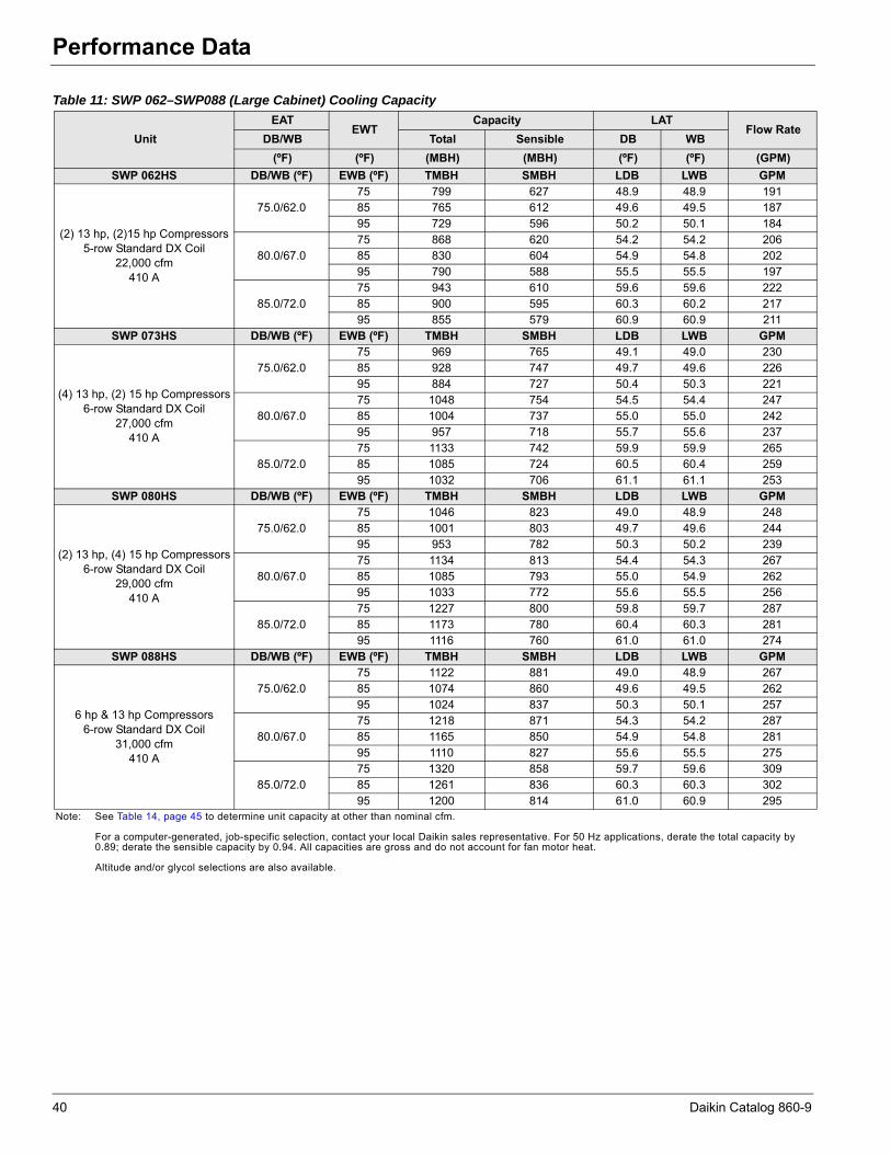
Performance Data
Table 11: SWP 062–SWP088 (Large Cabinet) Cooling Capacity
UnitEAT
EWTCapacity LAT
Flow RateDB/WB Total Sensible DB WB
(ºF) (ºF) (MBH) (MBH) (ºF) (ºF) (GPM)SWP 062HS DB/WB (ºF) EWB (ºF) TMBH SMBH LDB LWB GPM
(2) 13 hp, (2)15 hp Compressors5-row Standard DX Coil
22,000 cfm410 A
75.0/62.075 799 627 48.9 48.9 19185 765 612 49.6 49.5 18795 729 596 50.2 50.1 184
80.0/67.075 868 620 54.2 54.2 20685 830 604 54.9 54.8 20295 790 588 55.5 55.5 197
85.0/72.075 943 610 59.6 59.6 22285 900 595 60.3 60.2 21795 855 579 60.9 60.9 211
SWP 073HS DB/WB (ºF) EWB (ºF) TMBH SMBH LDB LWB GPM
(4) 13 hp, (2) 15 hp Compressors6-row Standard DX Coil
27,000 cfm410 A
75.0/62.075 969 765 49.1 49.0 23085 928 747 49.7 49.6 22695 884 727 50.4 50.3 221
80.0/67.075 1048 754 54.5 54.4 24785 1004 737 55.0 55.0 24295 957 718 55.7 55.6 237
85.0/72.075 1133 742 59.9 59.9 26585 1085 724 60.5 60.4 25995 1032 706 61.1 61.1 253
SWP 080HS DB/WB (ºF) EWB (ºF) TMBH SMBH LDB LWB GPM
(2) 13 hp, (4) 15 hp Compressors6-row Standard DX Coil
29,000 cfm410 A
75.0/62.075 1046 823 49.0 48.9 24885 1001 803 49.7 49.6 24495 953 782 50.3 50.2 239
80.0/67.075 1134 813 54.4 54.3 26785 1085 793 55.0 54.9 26295 1033 772 55.6 55.5 256
85.0/72.075 1227 800 59.8 59.7 28785 1173 780 60.4 60.3 28195 1116 760 61.0 61.0 274
SWP 088HS DB/WB (ºF) EWB (ºF) TMBH SMBH LDB LWB GPM
6 hp & 13 hp Compressors6-row Standard DX Coil
31,000 cfm410 A
75.0/62.075 1122 881 49.0 48.9 26785 1074 860 49.6 49.5 26295 1024 837 50.3 50.1 257
80.0/67.075 1218 871 54.3 54.2 28785 1165 850 54.9 54.8 28195 1110 827 55.6 55.5 275
85.0/72.075 1320 858 59.7 59.6 30985 1261 836 60.3 60.3 30295 1200 814 61.0 60.9 295
Note: See Table 14, page 45 to determine unit capacity at other than nominal cfm.
For a computer-generated, job-specific selection, contact your local Daikin sales representative. For 50 Hz applications, derate the total capacity by 0.89; derate the sensible capacity by 0.94. All capacities are gross and do not account for fan motor heat.
Altitude and/or glycol selections are also available.
40 Daikin Catalog 860-9
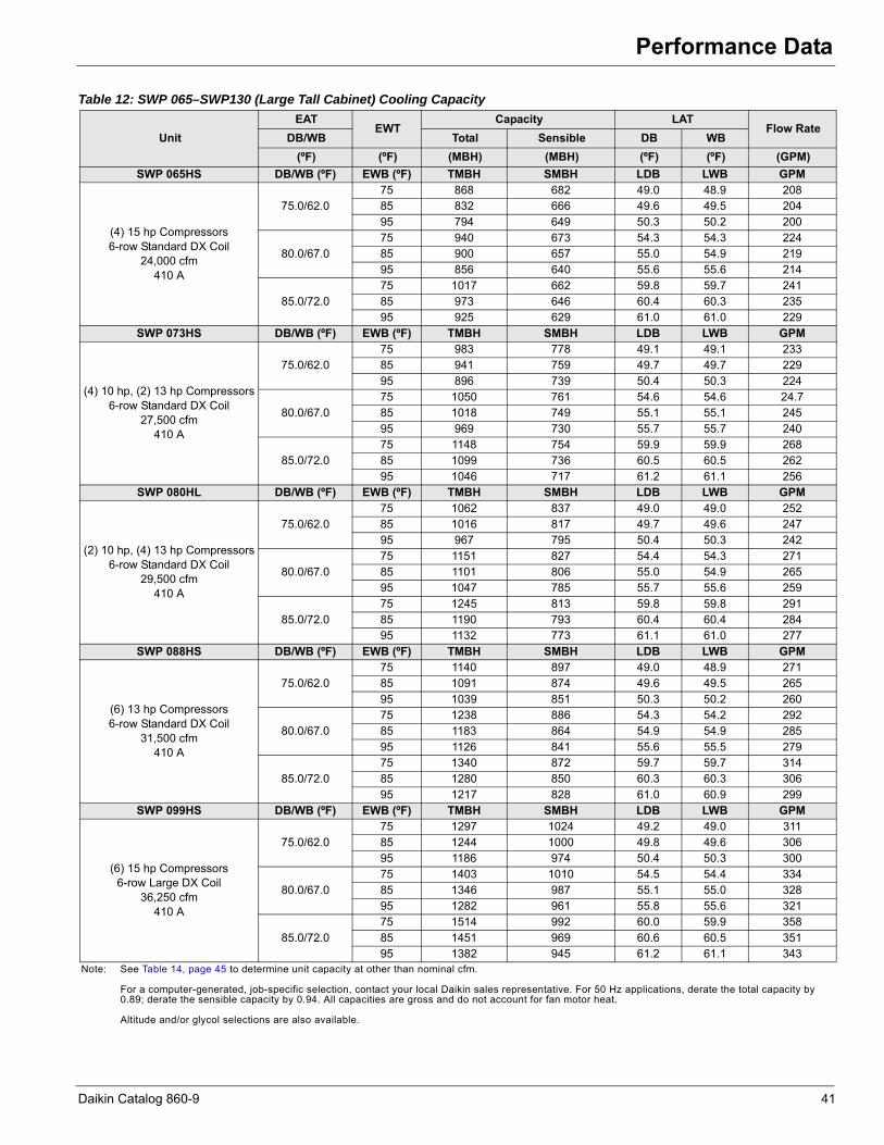
Performance Data
Table 12: SWP 065–SWP130 (Large Tall Cabinet) Cooling Capacity
UnitEAT
EWTCapacity LAT
Flow RateDB/WB Total Sensible DB WB
(ºF) (ºF) (MBH) (MBH) (ºF) (ºF) (GPM)SWP 065HS DB/WB (ºF) EWB (ºF) TMBH SMBH LDB LWB GPM
(4) 15 hp Compressors6-row Standard DX Coil
24,000 cfm410 A
75.0/62.075 868 682 49.0 48.9 20885 832 666 49.6 49.5 20495 794 649 50.3 50.2 200
80.0/67.075 940 673 54.3 54.3 22485 900 657 55.0 54.9 21995 856 640 55.6 55.6 214
85.0/72.075 1017 662 59.8 59.7 24185 973 646 60.4 60.3 23595 925 629 61.0 61.0 229
SWP 073HS DB/WB (ºF) EWB (ºF) TMBH SMBH LDB LWB GPM
(4) 10 hp, (2) 13 hp Compressors6-row Standard DX Coil
27,500 cfm410 A
75.0/62.075 983 778 49.1 49.1 23385 941 759 49.7 49.7 22995 896 739 50.4 50.3 224
80.0/67.075 1050 761 54.6 54.6 24.785 1018 749 55.1 55.1 24595 969 730 55.7 55.7 240
85.0/72.075 1148 754 59.9 59.9 26885 1099 736 60.5 60.5 26295 1046 717 61.2 61.1 256
SWP 080HL DB/WB (ºF) EWB (ºF) TMBH SMBH LDB LWB GPM
(2) 10 hp, (4) 13 hp Compressors6-row Standard DX Coil
29,500 cfm410 A
75.0/62.075 1062 837 49.0 49.0 25285 1016 817 49.7 49.6 24795 967 795 50.4 50.3 242
80.0/67.075 1151 827 54.4 54.3 27185 1101 806 55.0 54.9 26595 1047 785 55.7 55.6 259
85.0/72.075 1245 813 59.8 59.8 29185 1190 793 60.4 60.4 28495 1132 773 61.1 61.0 277
SWP 088HS DB/WB (ºF) EWB (ºF) TMBH SMBH LDB LWB GPM
(6) 13 hp Compressors6-row Standard DX Coil
31,500 cfm410 A
75.0/62.075 1140 897 49.0 48.9 27185 1091 874 49.6 49.5 26595 1039 851 50.3 50.2 260
80.0/67.075 1238 886 54.3 54.2 29285 1183 864 54.9 54.9 28595 1126 841 55.6 55.5 279
85.0/72.075 1340 872 59.7 59.7 31485 1280 850 60.3 60.3 30695 1217 828 61.0 60.9 299
SWP 099HS DB/WB (ºF) EWB (ºF) TMBH SMBH LDB LWB GPM
(6) 15 hp Compressors6-row Large DX Coil
36,250 cfm410 A
75.0/62.075 1297 1024 49.2 49.0 31185 1244 1000 49.8 49.6 30695 1186 974 50.4 50.3 300
80.0/67.075 1403 1010 54.5 54.4 33485 1346 987 55.1 55.0 32895 1282 961 55.8 55.6 321
85.0/72.075 1514 992 60.0 59.9 35885 1451 969 60.6 60.5 35195 1382 945 61.2 61.1 343
Note: See Table 14, page 45 to determine unit capacity at other than nominal cfm.
For a computer-generated, job-specific selection, contact your local Daikin sales representative. For 50 Hz applications, derate the total capacity by 0.89; derate the sensible capacity by 0.94. All capacities are gross and do not account for fan motor heat.
Altitude and/or glycol selections are also available.
Daikin Catalog 860-9 41

Performance Data
SWP 099HL DB/WB (ºF) EWB (ºF) TMBH SMBH LDB LWB GPM
(6) 15 hp Compressors6-row Large DX Coil
36,250 cfm410 A
75.0/62.075 1313 1032 49.0 48.9 31485 1259 1008 49.6 49.5 30995 1200 982 50.2 50.1 303
80.0/67.075 1420 1018 54.3 54.3 33885 1362 994 54.9 54.8 33195 1297 969 55.6 55.5 324
85.0/72.075 1531 999 59.8 59.8 36285 1468 976 60.4 60.3 35595 1398 952 61.0 60.9 346
SWP 105HS DB/WB (ºF) EWB (ºF) TMBH SMBH LDB LWB GPM
(8) 13 hp Compressors6-row Standard DX Coil
36,500 cfm410 A
75.0/62.075 1390 1070 48.2 48.1 33385 1334 1045 48.8 48.8 32895 1275 1018 49.5 49.4 323
80.0/67.075 1517 1060 53.5 53.4 36085 1454 1034 54.1 54.1 35395 1387 1007 54.8 54.7 347
85.0/72.075 1654 1046 58.8 58.8 39085 1583 1020 59.4 59.4 38195 1508 993 60.1 60.1 373
SWP 105HL DB/WB (ºF) EWB (ºF) TMBH SMBH LDB LWB GPM
(8) 13 hp Compressors6-row Large DX Coil
41,000 cfm410 A
75.0/62.075 1470 1161 49.1 49.1 35085 1407 1132 49.7 49.7 34495 1341 1103 50.4 50.3 337
80.0/67.075 1600 1148 54.4 54.3 37885 1528 1119 55.0 55.0 36995 1452 1090 55.7 55.6 361
85.0/72.075 1741 1133 59.7 59.7 40885 1660 1104 60.4 60.3 39895 1576 1074 61.1 61.0 388
SWP 120HS DB/WB (ºF) EWB (ºF) TMBH SMBH LDB LWB GPM
(4) 13 hp, (4) 15 hp Compressors6-row Standard DX Coil
36,500 cfm410 A
75.0/62.075 1458 1101 47.4 47.4 35285 1401 1075 48.1 48.0 34795 1339 1047 48.8 48.7 342
80.0/67.075 1592 1091 52.7 52.6 38185 1528 1064 53.3 53.3 37495 1459 1036 54.0 54.0 368
85.0/72.075 1736 1076 58.0 58.0 41285 1664 1050 58.7 58.7 40395 1586 1021 59.4 59.4 395
SWP 120HL DB/WB (ºF) EWB (ºF) TMBH SMBH LDB LWB GPM
(4) 13 hp, (4) 15 hp Compressors6-row Large DX Coil
42,000 cfm410 A
75.0/62.075 1547 1208 48.7 48.7 37185 1481 1178 49.4 49.3 36495 1411 1147 50.0 50.0 357
80.0/67.075 1685 1195 54.0 53.9 40185 1611 1165 54.6 54.6 39295 1533 1134 55.3 55.3 384
85.0/72.075 1833 1178 59.4 59.3 43385 1750 1148 60.0 60.0 42295 1663 1117 60.7 60.6 412
Note: See Table 14, page 45 to determine unit capacity at other than nominal cfm.
For a computer-generated, job-specific selection, contact your local Daikin sales representative. For 50 Hz applications, derate the total capacity by 0.89; derate the sensible capacity by 0.94. All capacities are gross and do not account for fan motor heat.
Altitude and/or glycol selections are also available.
Table 12: SWP 065–SWP130 (Large Tall Cabinet) Cooling Capacity
42 Daikin Catalog 860-9
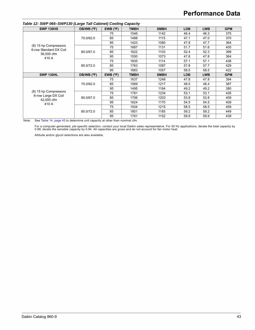
Performance Data
SWP 130HS DB/WB (ºF) EWB (ºF) TMBH SMBH LDB LWB GPM
(8) 15 hp Compressors6-row Standard DX Coil
36,500 cfm410 A
75.0/62.075 1546 1142 46.4 46.3 37585 1488 1115 47.1 47.0 37095 1423 1085 47.8 47.7 364
80.0/67.075 1687 1131 51.7 51.6 40585 1622 1103 52.4 52.3 39995 1550 1073 47.8 47.8 364
85.0/72.075 1835 1114 57.1 57.1 43885 1763 1087 57.8 57.7 42995 1683 1057 58.5 58.5 422
SWP 130HL DB/WB (ºF) EWB (ºF) TMBH SMBH LDB LWB GPM
(8) 15 hp Compressors6-row Large DX Coil
42,000 cfm410 A
75.0/62.075 1637 1248 47.8 47.8 39485 1569 1217 48.5 48.4 38795 1495 1184 49.2 49.2 380
80.0/67.075 1781 1234 53.1 53.1 42685 1706 1203 53.8 53.8 40995 1624 1170 54.5 54.5 409
85.0/72.075 1934 1215 58.5 58.5 45985 1851 1185 59.2 59.2 44995 1761 1152 59.9 59.9 439
Note: See Table 14, page 45 to determine unit capacity at other than nominal cfm.
For a computer-generated, job-specific selection, contact your local Daikin sales representative. For 50 Hz applications, derate the total capacity by 0.89; derate the sensible capacity by 0.94. All capacities are gross and do not account for fan motor heat.
Altitude and/or glycol selections are also available.
Table 12: SWP 065–SWP130 (Large Tall Cabinet) Cooling Capacity
Daikin Catalog 860-9 43

Performance Data
Waterside Economizer CapacityTable 13: Waterside Economizer Coil Face Area17.2 Square Feet 25.2 Square Feet
EWT EAT Nominal Airflow
Flow Rate Capacity Nominal
AirflowFlow Rate Capacity
Nominal Airflow Nominal
AirflowFlow Rate Capacity Nominal
AirflowFlow Rate Capacity
EWT EAT
(ºF)DB/WB
(cfm) (gpm)Total Sensible
(cfm) (gpm)Total Sensible
(ºF)DB/WB
(cfm) (gpm)Total Sensible
(cfm) (gpm)Total Sensible
(ºF) (Btu/hr) (Btu/hr) (Btu/hr) (Btu/hr) (ºF) (Btu/hr) (Btu/hr) (Btu/hr) (Btu/hr)
45
75.0/ 62.0
4300
43.0 118215 104308
8750
98.4 247233 212158
45
75.0/62.0
5750
70.8 174932 147468
11250
202.5 328039 27846635.7 105670 98166 81.7 231712 204722 58.8 158718 140000 168.0 307473 26874328.4 89506 88546 65.0 210613 194026 46.8 137193 129347 133.4 278405 254363
80.0/ 67.0
43.0 153149 113374 98.4 325916 23338580.0/67.0
70.8 230503 162275 202.5 434409 30730735.7 133765 105547 81.7 301172 223270 58.8 205708 152163 168.0 400795 29354328.4 109640 95570 65.0 268225 209766 46.8 172394 138737 133.4 355858 275180
55
75.0/ 62.0
43.0 76546 76546 98.4 15226 152261
55
75.0/62.0
70.8 107987 107987 202.5 200490 20049035.7 71725 71725 81.7 147128 147128 58.8 103013 103013 168.0 193879 19387928.4 63936 63936 98.4 138920 138920 46.8 94517 94517 133.4 183078 183078
80.0/ 67.0
43.0 997707 92120 81.7 201228 18342780.0/67.0
70.8 145162 128577 202.5 267384 24068635.7 91330 87908 65.0 190980 178438 58.8 134265 12384 168.0 253334 23414728.4 80220 80201 98.4 176565 170614 46.8 119858 116468 133.4 234216 224149
29.8 Square Feet 40.8 Square FeetNominal Airflow Nominal
Airflow
Flow Rate Capacity Nominal
Airflow
Flow Rate Capacity
Nominal Airflow Nominal
AirflowFlow Rate Capacity Nominal
AirflowFlow Rate Capacity
EWT EATEWT EAT
(gpm)Total Sensible
(gpm)Total Sensible
(ºF)DB/WB
(cfm) (gpm)Total Sensible
(cfm) (gpm)Total Sensible
(ºF) DB/WB (cfm) (Btu/hr) (Btu/hr) (cfm) (Btu/hr) (Btu/hr) (ºF) (Btu/hr) (Btu/hr) (Btu/hr) (Btu/hr)
45
75.0/62.0
10000
120.1 300141 252991
12500
150.6 369070 311969
45
75.0/62.0
11250
138.4 312851 268478
16500
200.9 518514 42647099.7 277844 242600 125.1 345207 300757 115.0 297133 260929 166.8 490321 41344179.4 247291 227625 99.2 311526 284209 91.3 275216 249921 132.4 450026 394389
80.0/67.0
120.1 396773 279042 150.6 488735 34439380.0/67.0
138.4 414192 296028 200.9 689345 47323599.7 361929 264763 125.1 450654 328782 115.0 387874 285299 166.8 647073 45570479.4 314626 245527 99.2 376624 298517 91.3 353829 271344 132.4 584177 429857
55
75.0/62.0
120.1 183343 183343 150.6 224803 224803
55
75.0/62.0
138.4 191437 191437 200.9 305575 30557599.7 176480 176480 125.1 217345 217345 115.0 186084 186084 166.8 297975 29797579.4 165073 165073 99.2 204979 204979 91.3 177930 177930 132.4 285222 285222
80.0/67.0
120.1 246079 219190 150.6 300807 26952880.0/67.0
138.4 252970 231305 200.9 418034 36503499.7 231002 212437 125.1 284619 262106 115.0 242136 225955 166.8 398913 35671079.4 210726 202139 99.2 262399 250687 91.3 227979 218163 132.4 372003 344165
45.2 Square Feet 52.5 Square Feet
EWT EAT Nominal Airflow
Flow Rate Capacity Nominal
AirflowFlow Rate Capacity
Nominal Airflow Nominal
AirflowFlow Rate Capacity Nominal
AirflowFlow Rate Capacity
EWT EAT
(ºF)DB/WB
(cfm) (gpm)Total Sensible
(cfm) (gpm)Total Sensible
(ºF)DB/WB
(cfm) (gpm)Total Sensible
(cfm) (gpm)Total Sensible
(ºF) (Btu/hr) (Btu/hr) (Btu/hr) (Btu/hr) (ºF) (Btu/hr) (Btu/hr) (Btu/hr) (Btu/hr)
45
75.0/62.0
12500
155.4 410014 333157
16500
202.5 526221 430876
45
75.0/62.0
15500
191.3 530260 422617
22000
267.1 731367 588143129.0 382469 320590 168.0 495046 416563 158.9 504119 410660 221.0 696784 572268102.3 344216 302774 133.4 453219 396846 126.1 464227 392287 176.2 647897 549552
80.0/67.0
155.4 546475 370822 202.5 699525 47835880.0/67.0
191.3 711594 473799 267.1 979631 657637129.0 505143 353584 168.0 654992 459848 158.9 669318 455923 221.0 925183 634763102.3 445328 329064 133.4 588178 432393 126.1 608158 430457 176.2 847943 602685
55
75.0/62.0
155.4 240254 240254 202.5 309206 309206
55
75.0/62.0
191.3 301945 301945 267.1 419653 419653129.0 233413 233413 168.0 301287 301287 158.9 295956 295956 221.0 411289 411289102.3 221426 221426 133.4 287860 287860 126.1 285323 285323 176.2 397647 397647
80.0/67.0
155.4 332781 285581 202.5 425016 36887980.0/67.0
191.3 426964 359394 267.1 586400 500035129.0 314692 278020 168.0 404552 360100 158.9 408475 351794 221.0 562770 490066102.3 288623 266420 133.4 375762 346898 126.1 381148 340123 176.2 529279 475352
60.9 Square Feet 71.3 Square Feet
EWT EAT Nominal Airflow
Flow Rate Capacity Nominal
AirflowFlowRate Capacity
Nominal Airflow Nominal
AirflowFlow Rate Capacity Nominal
AirflowFlow Rate Capacity
EWT EAT
(ºF)DB/WB
(cfm) (gpm)Total Sensible
(cfm) (gpm)Total Sensible
(ºF)DB/WB
(cfm) (gpm)Total Sensible
(cfm) (gpm)Total Sensible
(ºF) (Btu/hr) (Btu/hr) (Btu/hr) (Btu/hr) (ºF) (Btu/hr) (Btu/hr) (Btu/hr) (Btu/hr)
45
75.0/62.0
16500
207.3 571870 453820
32000
391.7 1003513 820997
45
75.0/62.0
24750
312.1 834084 667291
32000
402.0 1037546 839692172.0 542915 440594 325.6 958766 800336 259.3 797101 650336 333.0 991370 818465136.5 498560 420239 258.3 903504 774109 264.8 1119379 747621 264.8 931326 790353
80.0/67.0
207.3 768359 509542 391.7 1339061 91350880.0/67.0
312.1 1119379 747621 402.0 1388369 937345172.0 720933 489427 325.6 1277444 887940 259.3 1059374 722329 333.0 1318009 907963136.5 653719 461401 258.3 1183607 849179 264.8 755519 681094 264.8 1221011 867762
55
75.0/62.0
207.3 324297 324297 391.7 584577 584577
55
75.0/62.0
312.1 475642 475642 402.0 597600 597600172.0 317813 317813 325.6 572669 572669 259.3 466859 466859 333.0 585855 585855136.5 306263 306263 258.3 554618 554618 264.8 669195 566903 264.8 568232 568232
80.0/67.0
207.3 461349 385934 391.7 804567 70000580.0/67.0
312.1 669195 566903 402.0 829035 713591172.0 439485 377081 325.6 773282 686291 259.3 642967 555976 333.0 797971 700186136.5 410083 364614 258.3 732310 667233 264.8 732310 667233 264.8 755519 681094
Note: See Table 15, page 45 to determine capacity at other than nominal cfm.
44 Daikin Catalog 860-9

Performance Data
Table 15: DX Cooling Capacity Correction Multipliers
Heating Capacity DataHot Water Coil Capacity (2-row)1
Steam Coil Capacity1
Table 14: Waterside Economizer Capacity Correction Factors
DescriptionPercent Standard CFM
–20% –15% –10% –5% Standard 5% 10% 15% 20%Total Capacity 0.892 0.920 0.947 0.975 1.000 1.025 1.048 1.071 1.093
Sensible Capacity 0.848 0.886 0.925 0.963 1.000 1.037 1.072 1.107 1.142
DescriptionPercent Standard CFM
–20% –15% –10% –5% Standard 5% 10% 15% 20%Total Capacity 0.957 0.969 0.981 0.991 1.000 1.009 1.017 1.023 1.030
Sensible Capacity 0.895 0.921 0.948 0.974 1.000 1.026 1.052 1.077 1.102Compressor Motor kW 0.987 0.989 0.996 0.998 1.000 1.004 1.006 1.008 1.011
Table 16: Entering Water 160ºFand Entering Air 60ºF
Cabinet SizeMinimum Coil Face Area (ft2)2
Nominal Air Flow
(cfm)
Total Capacity
(MBH)
LWT(ºF)
LBD(ºF)
Flow Rate(gpm)
Air Pressure Drop
(in. wg)
Small 19.84300 241.3 125.8 111.3 14 0.095750 312.2 126.9 109.7 19 0.158750 441.4 129.2 106.1 29 0.30
Small Tall 19.8
5750 312.2 126.9 109.7 19 0.1510000 490.2 130.1 104.8 33 0.3711250 537.0 130.9 103.7 37 0.4512500 581.8 131.6 102.6 41 0.53
Medium 32.311250 613.3 126.8 109.9 37 0.2012500 667.9 127.4 108.9 41 0.2416500 831.8 129.3 106.1 54 0.38
Large 36.715500 836.5 127.1 109.4 51 0.3416500 879.0 128.5 108.7 54 0.3822000 1097.8 129.6 105.6 72 0.61
Large Tall 45.8
16500 919.2 126.0 110.9 54 0.2124750 1266.3 128.8 106.8 81 0.4132000 1536.9 130.7 103.9 105 0.6332500 1554.6 130.8 103.7 107 0.65
Note: 1 Based on 12 fpi aluminum HI-F5 fins with single serpentine.2 Smallest standard coil face area available using Daikin Vision™ air handling unit platform.
Table 17: Steam Pressure 5 psi and Entering Air 60ºF
Cabinet Size Minimum Coil Face Area (ft2)2
Nominal Air Flow (cfm)
Total Capacity(MBH) LBD (ºF) Air Pressure Drop
(in. wg)
Small 19.84300 227.5 119.0 0.035750 330.1 112.5 0.058750 420.1 103.9 0.10
Small Tall 19.8
5750 330.1 112.5 0.0510000 452.0 101.3 0.1311250 481.4 99.1 0.1612500 508.9 97.2 0.20
Medium 32.311250 598.2 108.6 0.0712500 635.4 106.5 0.0816500 740.8 101.1 0.13
Large 36.715500 758.5 104.8 0.1216500 785.3 103.5 0.1322000 916.9 98.1 0.23
Large Tall 45.8
16500 865.8 108.0 0.0724750 1083.9 100.0 0.1532000 1239.8 95.4 0.2432500 1249.7 95.2 0.24
Note: 1 Based on 5 psi steam pressure and 6 fpi aluminum HI-F5 fins.2 Smallest standard coil face area available using Daikin Vision™ air handling unit platform.
Daikin Catalog 860-9 45

Performance Data
Electric HeatComponent Pressure Drops
Table 18: Electric Heat – 60 Hz, 3 Phase
SWP Unit Size208 V/60 Hz/3 Phase 230 V/60 Hz/3 Phase 460 V/60 Hz/3 Phase 575 V/60 Hz/3 PhasekW MBH FLA kW MBH FLA kW MBH FLA kW MBH FLA
023 through 035 27.8 94 77.2 34.0 116 85.6 34.0 116 42.8 34.0 116 34.2039 through 050 27.8 94 77.2 34.0 116 85.6 68.0 232 85.6 68.0 232 68.4044 through 066 27.8 94 77.2 34.0 116 85.6 68.0 232 85.6 68.0 232 68.4062 through 088 55.6 190 154.4 68.0 232 170.9 68.0 232 85.6 68.0 232 68.4065 through 130 55.6 190 154.4 68.0 232 170.9 68.0 232 85.6 68.0 232 68.4
Table 19: SWP 023 through 033 (pressure drop in inches wg)
NominalAir Flow
(cfm)
Standard Coil Filters Discharge Plenum17.2 ft2
2", 30% 2", 75% 4", 30% 4", 65% 4", 75% 2", 85% Left &Right
Front & BackEvaporator Economizer
4000 0.26 0.13 0.09 0.11 0.09 0.14 0.07 0.24 0.01 0.006000 0.48 0.25 0.18 0.20 0.16 0.25 0.13 0.43 0.01 0.018000 0.73 0.41 0.31 0.31 0.25 0.40 0.21 0.64 0.03 0.01
10000 1.02 0.6 0.45 0.42 0.34 0.57 0.29 0.88 0.04 0.01
NominalAir Flow
(cfm)
Large Coil Filters Discharge Plenum25.2 ft2
2", 30% 2", 75% 4", 30% 4", 65% 4", 75% 2", 85% Left &Right
Front & BackEvaporator Economizer
6000 0.27 0.13 0.09 0.11 0.10 0.14 0.08 0.25 0.01 0.018000 0.41 0.21 0.16 0.17 0.14 0.22 0.12 0.37 0.02 0.01
10000 0.58 0.31 0.23 0.24 0.20 0.32 0.16 0.51 0.04 0.0112000 0.75 0.43 0.32 0.32 0.26 0.42 0.21 0.66 0.06 0.0214000 0.95 0.56 0.42 0.40 0.32 0.53 0.27 0.82 0.08 0.0316000 1.11 0.6 0.53 0.48 0.39 0.65 0.33 0.99 0.10 0.04
Note: DX pressure drops are wet coil and economizers are dry coil.All units must have a DX coil pressure drop.Based on 32" high plenum with maximum allowed opening.
Table 20: SWP 039 through 050 (pressure drop in inches wg)
NominalAir Flow
(cfm)
Standard Coil Filters Discharge Plenum25.2 ft2
2", 30% 2", 75% 4", 30% 4", 65% 4", 75% 2", 85% Left &Right
Front & BackEvaporator Economizer
6000 0.27 0.13 0.09 0.11 0.10 0.14 0.08 0.25 0.01 0.018000 0.41 0.21 0.16 0.17 0.14 0.22 0.12 0.37 0.03 0.01
10000 0.55 0.31 0.23 0.24 0.20 0.32 0.16 0.51 0.04 0.0112000 0.72 0.43 0.32 0.32 0.26 0.42 0.21 0.66 0.06 0.0216000 0.88 0.56 0.42 0.40 0.32 0.53 0.27 0.82 0.08 0.03
NominalAir Flow
(cfm)
Large Coil Filters Discharge Plenum29.8 ft2
2", 30% 2", 75% 4", 30% 4", 65% 4", 75% 2", 85% Left &Right
Front & BackEvaporator Economizer
10000 0.45 0.24 0.17 0.19 0.16 0.24 0.13 0.40 0.04 0.0112000 0.59 0.32 0.24 0.25 0.20 0.32 0.17 0.52 0.06 0.0214000 0.74 0.42 0.31 0.31 0.25 0.41 0.21 0.65 0.08 0.0316000 0.88 0.53 0.39 0.38 0.31 0.50 0.25 0.78 0.10 0.04
Note: DX pressure drops are wet coil and economizers are dry coil.All units must have a DX coil pressure drop.Based on 32" high plenum with maximum allowed opening.
46 Daikin Catalog 860-9

Performance Data
Table 21: SWP 044 through 065 (pressure drop in inches wg)
NominalAir Flow
(cfm)
Standard Coil Filters Discharge Plenum40.8 ft2
2", 30% 2", 75% 4", 30% 4", 65% 4", 75% 2", 85% Left &Right
Front & BackEvaporator Economizer
10000 0.28 0.14 0.10 0.12 0.10 0.15 0.08 0.26 0.03 0.0112000 0.37 0.19 0.14 0.16 0.13 0.20 0.10 0.33 0.05 0.0114000 0.46 0.24 0.18 0.20 0.16 0.25 0.13 0.42 0.06 0.0216000 0.48 0.31 0.23 0.24 0.19 0.31 0.16 .050 0.08 0.0218000 0.65 0.38 0.28 0.28 0.23 0.37 0.19 0.59 0.10 0.0320000 0.76 0.45 0.34 0.33 0.27 0.44 .022 0.69 0.13 0.0422000 0.86 0.53 0.40 0.38 0.31 0.51 0.26 0.79 0.16 0.0424000 0.98 0.61 0.46 0.43 0.35 0.58 0.29 0.89 0.18 0.05
NominalAir Flow
(cfm)
Large Coil Filters Discharge Plenum45.8 ft2
2", 30% 2", 75% 4", 30% 4", 65% 4", 75% 2", 85% Left &Right
Front & BackEvaporator Economizer
12000 0.32 0.16 0.11 0.13 0.11 0.17 0.09 .028 0.05 0.0114000 0.40 0.21 0.15 0.17 0.14 0.21 0.11 0.35 0.06 0.0216000 0.55 0.26 0.19 0.20 0.17 0.26 0.13 0.43 0.08 0.0218000 0.56 0.32 0.23 0.24 0.20 0.31 0.16 0.50 0.10 0.0320000 0.64 0.38 0.27 0.28 0.23 0.37 0.19 0.58 0.13 0.0422000 0.74 0.44 0.32 0.32 0.26 0.42 0.22 0.67 0.16 0.0424000 0.84 0.51 0.38 0.36 0.29 0.48 0.25 0.76 0.18 0.0526000 0.94 0.59 0.43 0.41 0.33 0.55 0.28 0.85 0.22 0.06
Note: DX pressure drops are wet coil and economizers are dry coil.All units must have a DX coil pressure drop.Based on 32" high plenum with maximum allowed opening.
Table 22: SWP 062 through 088 (pressure drop in inches wg)
NominalAir Flow
(cfm)
Standard Coil Filters Discharge Plenum52.5 ft2
2", 30% 2", 75% 4", 30% 4", 65% 4", 75% 2", 85% Left &Right
Front & BackEvaporator Economizer
12000 0.26 0.12 0.09 0.11 0.09 0.14 0.07 0.23 0.03 0.0114000 0.38 .012 0.12 0.14 0.11 0.17 0.09 0.29 0.04 0.0116000 0.45 0.16 0.15 0.16 0.14 0.21 0.11 0.35 0.05 0.0118000 0.53 0.19 0.18 0.20 0.16 0.25 0.13 0.42 0.07 0.0220000 0.62 0.23 0.22 0.23 0.19 0.30 0.15 0.48 0.09 0.0222000 0.70 0.27 0.26 0.26 0.21 0.34 0.18 0.55 0.10 0.0324000 0.80 0.31 0.30 0.30 0.24 0.39 0.20 .062 0.12 0.0326000 0.91 0.35 0.34 0.33 0.27 0.44 0.23 0.70 0.14 0.0428000 1.01 0.40 0.39 0.37 0.30 0.50 0.25 0.78 0.17 0.0430000 1.13 0.45 0.44 0.41 0.33 0.55 0.28 0.86 0.19 0.05
Note: DX pressure drops are wet coil and economizers are dry coil.All units must have a DX coil pressure drop.Based on 32" high plenum with maximum allowed opening.
Daikin Catalog 860-9 47
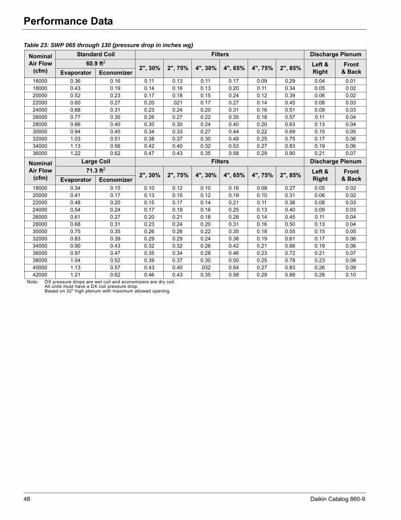
Performance Data
Table 23: SWP 065 through 130 (pressure drop in inches wg)
NominalAir Flow
(cfm)
Standard Coil Filters Discharge Plenum60.9 ft2
2", 30% 2", 75% 4", 30% 4", 65% 4", 75% 2", 85% Left &Right
Front & BackEvaporator Economizer
16000 0.36 0.16 0.11 0.13 0.11 0.17 0.09 0.29 0.04 0.0118000 0.43 0.19 0.14 0.16 0.13 0.20 0.11 0.34 0.05 0.0220000 0.52 0.23 0.17 0.18 0.15 0.24 0.12 0.39 0.06 0.0222000 0.60 0.27 0.20 .021 0.17 0.27 0.14 0.45 0.08 0.0324000 0.68 0.31 0.23 0.24 0.20 0.31 0.16 0.51 0.09 0.0326000 0.77 0.35 0.26 0.27 0.22 0.35 0.18 0.57 0.11 0.0428000 0.86 0.40 0.30 0.30 0.24 0.40 0.20 0.63 0.13 0.0430000 0.94 0.45 0.34 0.33 0.27 0.44 0.22 0.69 0.15 0.0532000 1.03 0.51 0.38 0.37 0.30 0.49 0.25 0.75 0.17 0.0634000 1.13 0.56 0.42 0.40 0.32 0.53 0.27 0.83 0.19 0.0636000 1.22 0.62 0.47 0.43 0.35 0.58 0.29 0.90 0.21 0.07
NominalAir Flow
(cfm)
Large Coil Filters Discharge Plenum71.3 ft2
2", 30% 2", 75% 4", 30% 4", 65% 4", 75% 2", 85% Left &Right
Front & BackEvaporator Economizer
18000 0.34 0.15 0.10 0.12 0.10 0.16 0.08 0.27 0.05 0.0220000 0.41 0.17 0.13 0.15 0.12 0.19 0.10 0.31 0.06 0.0222000 0.48 0.20 0.15 0.17 0.14 0.21 0.11 0.36 0.08 0.0324000 0.54 0.24 0.17 0.19 0.16 0.25 0.13 0.40 0.09 0.0326000 0.61 0.27 0.20 0.21 0.18 0.28 0.14 0.45 0.11 0.0428000 0.68 0.31 0.23 0.24 0.20 0.31 0.16 0.50 0.13 0.0430000 0.75 0.35 0.26 0.26 0.22 0.35 0.18 0.55 0.15 0.0532000 0.83 0.39 0.29 0.29 0.24 0.38 0.19 0.61 0.17 0.0634000 0.90 0.43 0.32 0.32 0.26 0.42 0.21 0.66 0.19 0.0636000 0.97 0.47 0.35 0.34 0.28 0.46 0.23 0.72 0.21 0.0738000 1.04 0.52 0.39 0.37 0.30 0.50 0.25 0.78 0.23 0.0840000 1.13 0.57 0.43 0.40 .032 0.54 0.27 0.83 0.26 0.0942000 1.21 0.62 0.46 0.43 0.35 0.58 0.29 0.89 0.28 0.10
Note: DX pressure drops are wet coil and economizers are dry coil.All units must have a DX coil pressure drop.Based on 32" high plenum with maximum allowed opening.
48 Daikin Catalog 860-9
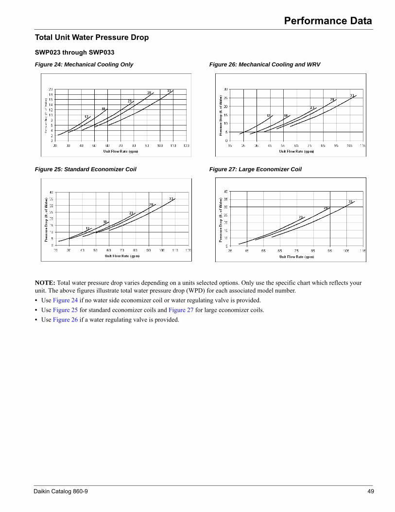
Performance Data
Total Unit Water Pressure DropSWP023 through SWP033
Figure 24: Mechanical Cooling Only
Figure 25: Standard Economizer Coil
Figure 26: Mechanical Cooling and WRV
Figure 27: Large Economizer Coil
NOTE: Total water pressure drop varies depending on a units selected options. Only use the specific chart which reflects your unit. The above figures illustrate total water pressure drop (WPD) for each associated model number.• Use Figure 24 if no water side economizer coil or water regulating valve is provided.• Use Figure 25 for standard economizer coils and Figure 27 for large economizer coils.• Use Figure 26 if a water regulating valve is provided.
Daikin Catalog 860-9 49
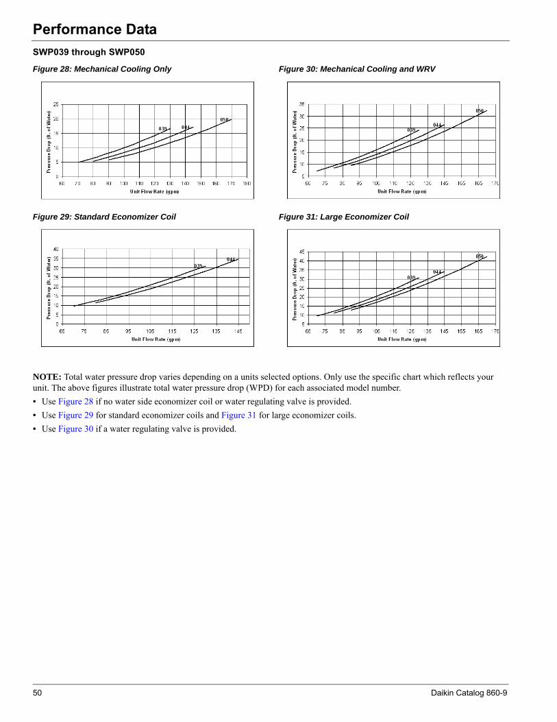
Performance Data
SWP039 through SWP050Figure 28: Mechanical Cooling Only
Figure 29: Standard Economizer Coil
Figure 30: Mechanical Cooling and WRV
Figure 31: Large Economizer Coil
NOTE: Total water pressure drop varies depending on a units selected options. Only use the specific chart which reflects your unit. The above figures illustrate total water pressure drop (WPD) for each associated model number.• Use Figure 28 if no water side economizer coil or water regulating valve is provided.• Use Figure 29 for standard economizer coils and Figure 31 for large economizer coils.• Use Figure 30 if a water regulating valve is provided.
50 Daikin Catalog 860-9

Performance Data
SWP044 through SWP055Figure 32: Mechanical Cooling Only
Figure 33: Standard Economizer Coil
Figure 34: Mechanical Cooling and WRV
Figure 35: Large Economizer Coil
NOTE: Total water pressure drop varies depending on a units selected options. Only use the specific chart which reflects your unit. The above figures illustrate total water pressure drop (WPD) for each associated model number.• Use Figure 32 if no water side economizer coil or water regulating valve is provided.• Use Figure 33 for standard economizer coils and Figure 35 for large economizer coils.• Use Figure 34 if a water regulating valve is provided.
Daikin Catalog 860-9 51

Performance Data
SWP062 through SWP088Figure 36: Mechanical Cooling Only
Figure 37: Standard Economizer Coil
Figure 38: Mechanical Cooling and WRV
NOTE: Total water pressure drop varies depending on a units selected options. Only use the specific chart which reflects your unit. The above figures illustrate total water pressure drop (WPD) for each associated model number.• Use Figure 36 if no water side economizer coil or water regulating valve is provided.• Use Figure 37 for standard economizer coils.• Use Figure 38 if a water regulating valve is provided.
52 Daikin Catalog 860-9
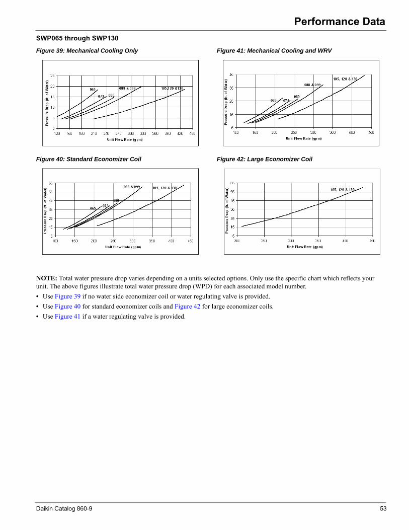
Performance Data
SWP065 through SWP130Figure 39: Mechanical Cooling Only
Figure 40: Standard Economizer Coil
Figure 41: Mechanical Cooling and WRV
Figure 42: Large Economizer Coil
NOTE: Total water pressure drop varies depending on a units selected options. Only use the specific chart which reflects your unit. The above figures illustrate total water pressure drop (WPD) for each associated model number.• Use Figure 39 if no water side economizer coil or water regulating valve is provided.• Use Figure 40 for standard economizer coils and Figure 42 for large economizer coils.• Use Figure 41 if a water regulating valve is provided.
Daikin Catalog 860-9 53

Performance Data
Total Unit Water Pressure DropSWP023 through SWP033
Figure 24: Mechanical Cooling Only
Figure 25: Standard Economizer Coil
Figure 26: Mechanical Cooling and WRV
Figure 27: Large Economizer Coil
NOTE: Total water pressure drop varies depending on a units selected options. Only use the specific chart which reflects your unit. The above figures illustrate total water pressure drop (WPD) for each associated model number.• Use Figure 24 if no water side economizer coil or water regulating valve is provided.• Use Figure 25 for standard economizer coils and Figure 27 for large economizer coils.• Use Figure 26 if a water regulating valve is provided.
Daikin Catalog 860-9 49
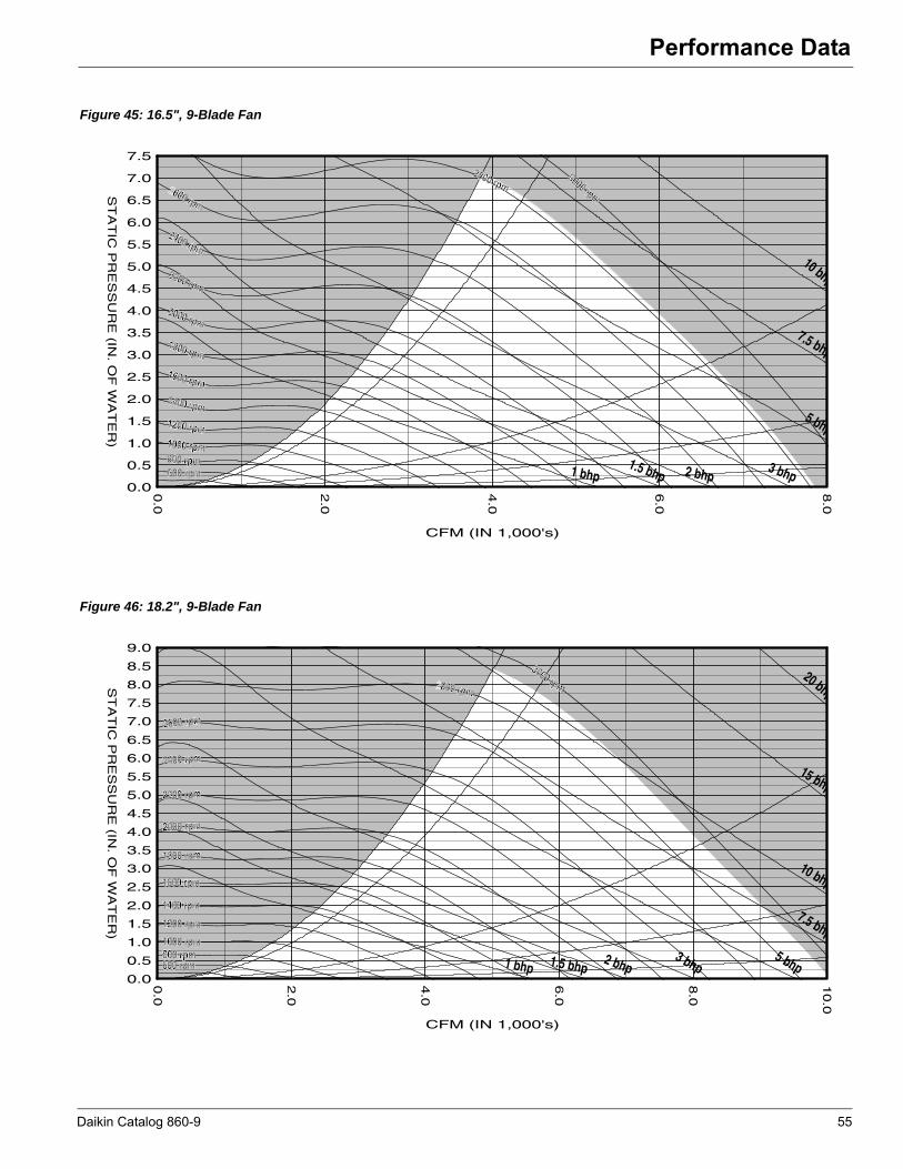
Performance Data
Figure 45: 16.5", 9-Blade Fan
Figure 46: 18.2", 9-Blade Fan
1 bhp1.5 bhp 2 bhp
3 bhp
5 bhp
7.5 bhp
10 bhp
0.0
0.5
1.0
1.5
2.0
2.5
3.0
3.5
4.0
4.5
5.0
5.5
6.0
6.5
7.0
7.5
ST
AT
IC P
RE
SS
UR
E (IN
. OF
WA
TE
R)
0.0
2.0
4.0
6.0
8.0
600 rpm
2800 rpm3000 rpm
2400 rpm
2200 rpm
2000 rpm
1800 rpm
1600 rpm
1400 rpm1200 rpm1000 rpm800 rpm600 rpm
1 bhp 1.5 bhp2 bhp
3 bhp5 bhp
7.5 bhp
10 bhp
15 bhp
20 bhp
0.0
0.5
1.0
1.5
2.0
2.5
3.0
3.5
4.0
4.5
5.0
5.5
6.0
6.5
7.0
7.5
8.0
8.5
9.0
ST
AT
IC P
RE
SS
UR
E (IN
. OF
WA
TE
R)
0.0
2.0
4.0
6.0
8.0
10.0
CFM (IN 1,000's)
800 rpm
3000 rpm
2600 rpm
2400 rpm
2200 rpm
2000 rpm
1800 rpm
1600 rpm
1400 rpm
1200 rpm
1000 rpm800 rpm600 rpm
CFM (IN 1,000's)
Daikin Catalog 860-9 55
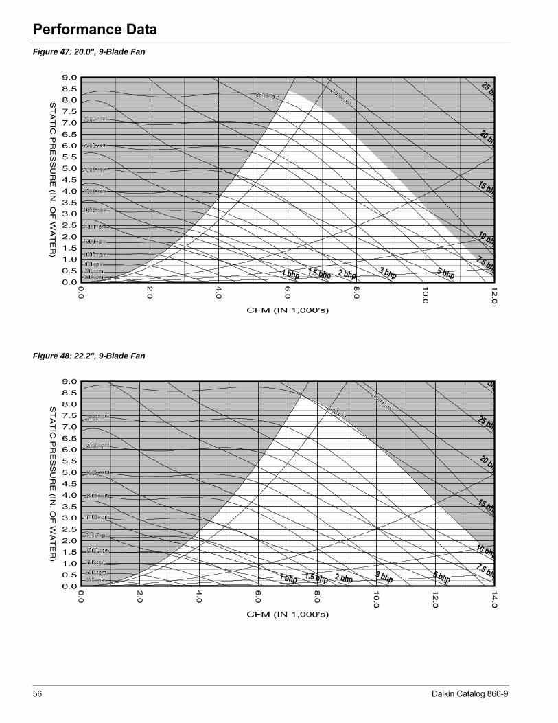
Performance Data
Figure 47: 20.0", 9-Blade FanFigure 48: 22.2", 9-Blade Fan
1 bhp 1.5 bhp 2 bhp3 bhp 5 bhp
7.5 bhp
10 bhp
15 bhp
20 bhp
25 bhp
0.0
0.5
1.0
1.5
2.0
2.5
3.0
3.5
4.0
4.5
5.0
5.5
6.0
6.5
7.0
7.5
8.0
8.5
9.0
ST
AT
IC P
RE
SS
UR
E (IN
. OF
WA
TE
R)
0.0
2.0
4.0
6.0
8.0
10.0
12.0
CFM (IN 1,000's)
2600 rpm2800 rpm
2400 rpm
2200 rpm
2000 rpm
1800 rpm
1600 rpm
1400 rpm
1200 rpm
1000 rpm800 rpm600 rpm400 rpm
1 bhp 1.5 bhp 2 bhp3 bhp 5 bhp
7.5 bhp
10 bhp
15 bhp
20 bhp
25 bhp
0 bhp
0.0
0.5
1.0
1.5
2.0
2.5
3.0
3.5
4.0
4.5
5.0
5.5
6.0
6.5
7.0
7.5
8.0
8.5
9.0
ST
AT
IC P
RE
SS
UR
E (IN
. OF
WA
TE
R)
0.0
2.0
4.0
6.0
8.0
10.0
12.0
14.0
CFM (IN 1,000's)
2600 rpm2400 rpm2200 rpm
2000 rpm
1800 rpm
1600 rpm
1400 rpm
1200 rpm
1000 rpm
800 rpm600 rpm400 rpm
56 Daikin Catalog 860-9

Performance Data
Figure 49: 24.5", 9-Blade FanFigure 50: 27.0", 9-Blade Fan
1 bhp 1.5 bhp 2 bhp3 bhp
5 bhp7.5 bhp
10 bhp
15 bhp
20 bhp
25 bhp
30 bhp
0.0
0.5
1.0
1.5
2.0
2.5
3.0
3.5
4.0
4.5
5.0
5.5
6.0
6.5
7.0
7.5
8.0
8.5
9.0
ST
AT
IC P
RE
SS
UR
E (IN
. OF
WA
TE
R)
0.0
2.0
4.0
6.0
8.0
10.0
12.0
14.0
16.0
18.0
CFM (IN 1,000's)
2200 rpm2000 rpm
1800 rpm
1600 rpm
1400 rpm
1200 rpm
1000 rpm
800 rpm
600 rpm400 rpm
1 bhp 1.5 bhp2 bhp
3 bhp 5 bhp7.5 bhp
10 bhp
15 bhp
20 bhp
25 bhp
30 bhp
40 bhp
0.0
0.5
1.0
1.5
2.0
2.5
3.0
3.5
4.0
4.5
5.0
5.5
6.0
6.5
7.0
7.5
8.0
ST
AT
IC P
RE
SS
UR
E (IN
. OF
WA
TE
R)
0.0
2.0
4.0
6.0
8.0
10.0
12.0
14.0
16.0
18.0
20.0
22.0
CFM (IN 1,000's)
1800 rpm 2000 rpm
1600 rpm
1400 rpm
1200 rpm
1000 rpm
800 rpm
600 rpm
400 rpm
Daikin Catalog 860-9 57
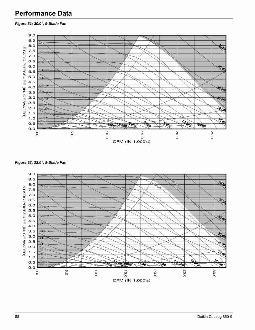
Performance Data
Figure 51: 30.0", 9-Blade FanFigure 52: 33.0", 9-Blade Fan
1 bhp 1.5 bhp2 bhp
3 bhp 5 bhp7.5 bhp 10 bhp
15 bhp
20 bhp
25 bhp
30 bhp
40 bhp
50 bhp
0.0
0.5
1.0
1.5
2.0
2.5
3.0
3.5
4.0
4.5
5.0
5.5
6.0
6.5
7.0
7.5
8.0
8.5
9.0
ST
AT
IC P
RE
SS
UR
E (IN
. OF
WA
TE
R)
0.0
5.0
10.0
15.0
20.0
25.0
CFM (IN 1,000's)
1700 rpm1800 rpm
1600 rpm
1500 rpm
1400 rpm
1300 rpm
1200 rpm
1000 rpm
900 rpm
800 rpm
700 rpm600 rpm500 rpm400 rpm
0110 rpm
1 bhp1.5 bhp 2 bhp
3 bhp5 bhp
7.5 bhp10 bhp
15 bhp
20 bhp
25 bhp
30 bhp
40 bhp
50 bhp
60 bhp
0.0
0.5
1.0
1.5
2.0
2.5
3.0
3.5
4.0
4.5
5.0
5.5
6.0
6.5
7.0
7.5
8.0
8.5
9.0
ST
AT
IC P
RE
SS
UR
E (IN
. OF
WA
TE
R)
0.0
5.0
10.0
15.0
20.0
25.0
30.0
CFM (IN 1,000's)
1600 rpm
1700 rpm1500 rpm
1400 rpm
1300 rpm
1200 rpm
1100 rpm
1000 rpm
900 rpm
800 rpm
700 rpm
600 rpm500 rpm400 rpm300 rpm
58 Daikin Catalog 860-9

Performance Data
Figure 53: 36.5", 9-Blade FanFigure 54: 40.2", 9-Blade Fan
1 bhp1.5 bhp2 bhp 3 bhp 5 bhp
7.5 bhp10 bhp
15 bhp
20 bhp
25 bhp
30 bhp
40 bhp
50 bhp
60 bhp
75 bhp
0.0
0.5
1.0
1.5
2.0
2.5
3.0
3.5
4.0
4.5
5.0
5.5
6.0
6.5
7.0
7.5
8.0
8.5
9.0
ST
AT
IC P
RE
SS
UR
E (IN
. OF
WA
TE
R)
0.0
5.0
10.0
15.0
20.0
25.0
30.0
35.0
CFM (IN 1,000's)
1400 rpm 1500 rpm
1300 rpm
1200 rpm
1100 rpm
1000 rpm
900 rpm
800 rpm
700 rpm
600 rpm500 rpm400 rpm300 rpm
1 bhp1.5 bhp2 bhp3 bhp 5 bhp
7.5 bhp10 bhp
15 bhp20 bhp
25 bhp
30 bhp
40 bhp
50 bhp
60 bhp
75 bhp
p
0.0
0.5
1.0
1.5
2.0
2.5
3.0
3.5
4.0
4.5
5.0
5.5
6.0
6.5
7.0
7.5
8.0
8.5
9.0
ST
AT
IC P
RE
SS
UR
E (IN
. OF
WA
TE
R)
0.0
5.0
10.0
15.0
20.0
25.0
30.0
35.0
40.0
45.0
CFM (IN 1,000's)
1300 rpm
1400 rpm1200 rpm
1100 rpm
1000 rpm
900 rpm
800 rpm
700 rpm
600 rpm
500 rpm
400 rpm300 rpm200 rpm
Daikin Catalog 860-9 59

Performance Data
Figure 55: 44.5", 9-Blade Fan1 bhp1.5 bhp2 bhp 3 bhp5 bhp
7.5 bhp10 bhp
15 bhp20 bhp
25 bhp30 bhp
40 bhp
50 bhp
60 bhp
75 bhp
100 bhp
0.0
0.5
1.0
1.5
2.0
2.5
3.0
3.5
4.0
4.5
5.0
5.5
6.0
6.5
7.0
7.5
8.0
8.5
9.0
ST
AT
IC P
RE
SS
UR
E (IN
. OF
WA
TE
R)
0.0
5.0
10.0
15.0
20.0
25.0
30.0
35.0
40.0
45.0
50.0
55.0
CFM (IN 1,000's)
1200 rpm
1300 rpm
1100 rpm
1000 rpm
900 rpm
800 rpm
700 rpm
600 rpm
500 rpm
400 rpm300 rpm200 rpm
60 Daikin Catalog 860-9

Dimensional Data
Dimensional DataRecommended ClearancesFor good installation, service and maintenance access, follow the recommended clearances given in this publication. Minimum clearances required by federal, state and local codes, such as the NEC, take precedence over the dimensions given. Clearance is required to allow room for side filter access, mechanical cleaning of condenser tubes, economizer coil access to expansion valves and other control components and allow for possible fan shaft or compressor removal.
Figure 56: Recommended Service and Maintainance Clearances
Table 24: Recommended Minimum Clearances
Location Clearance Length (Inches)Front 36Rear 24
Access Side 42Opposite Access Side 18
Note: For clearance requirements less than those indicated, contact your local Daikin sales representative.
Evaporator Coil
Motor
Con
trol
Pan
el
Airflow24"
See Note
18"or
24"
36"
42"
Rear Side
Front Side
OppositeAccess
SideAccess
Side
NOTE: If water and condenser drains are on the motor side, 24" is required.
Daikin Catalog 860-9 61

Dimensional Data
Figure 57: Self-Contained SWP—Front View (Left Hand Access Shown/Optional Plenum)Table 25: Dimensions (Inches)
Cabinet and Unit Sizes
Small Small Tall Medium Large Large Tall023-033 039-050 044-051 056-066 062-088 065-099 105-130
Total UnitHeight1, 2 80.0 84.0 96.0 96.0 96.0 112.0 112.0Width1, 2 84.0 84.0 102.0 102.0 126.0 126.0 126.0Depth1, 2 80.0 80.0 88.0 88.0 98.0 98.0 106.0
Power and Control KnockoutsEC1 5.5 5.5 7.5 7.5 7.5 7.5 7.5EC2 71.0 75.0 87.0 87.0 87.0 103.0 103.0
Plenum Width PW3, 4 70.0 70.0 86.0 86.0 110.0 110.0 110.0Plenum Depth PD3, 4 44.0 44.0 48.0 48.0 58.0 58.0 66.0
Condenser Water Connections (ODS)
WC1 23.0 23.0 25.0 25.0 27.0 27.0 27.0WC3 74.0 78.0 90.0 90.0 90.0 106.0 106.0DIA1 2.125 2.625 2.625 3.125 3.125 3.125 4.125DIA2 2.125 2.625 2.625 3.125 3.125 3.125 4.125
Drain Connections (MPT)DC1 18.0 18.0 20.0 20.0 20.0 20.0 20.0DC2 7.0 7.0 7.0 7.0 9.0 9.0 9.0
Fan Discharge OpeningDOD 32.0 32.0 32.0 32.0 32.0 40.0 40.0DOL 10.0 10.0 10.0 10.0 10.0 10.0 10.0DOW 52.0 52.0 68.0 68.0 92.0 92.0 92.0
Fan and Compressor Section Depth SD1 44.0 44.0 48.0 48.0 58.0 58.0 66.0
Coil Section Depth SD2 36.0 36.0 40.0 40.0 40.0 40.0 40.0Control Panel Width SW1 14.0 14.0 16.0 16.0 16.0 16.0 16.0
Note: 1 Dimensions do not include lifting lugs, handles, latches or fastener extensions.2 For shipping dimensions, add 4" to the depth, 8" to the length and 4" to the height.3 Plenum height is user configurable.4 Plenum opening height and width requires a minimum of 2" clearance on each side.
62 Daikin Catalog 860-9
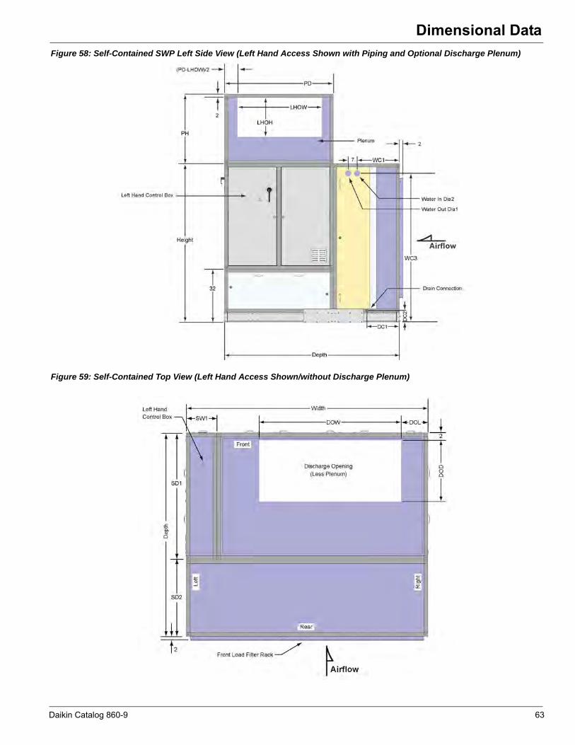
Dimensional Data
Figure 58: Self-Contained SWP Left Side View (Left Hand Access Shown with Piping and Optional Discharge Plenum)Figure 59: Self-Contained Top View (Left Hand Access Shown/without Discharge Plenum)
Daikin Catalog 860-9 63
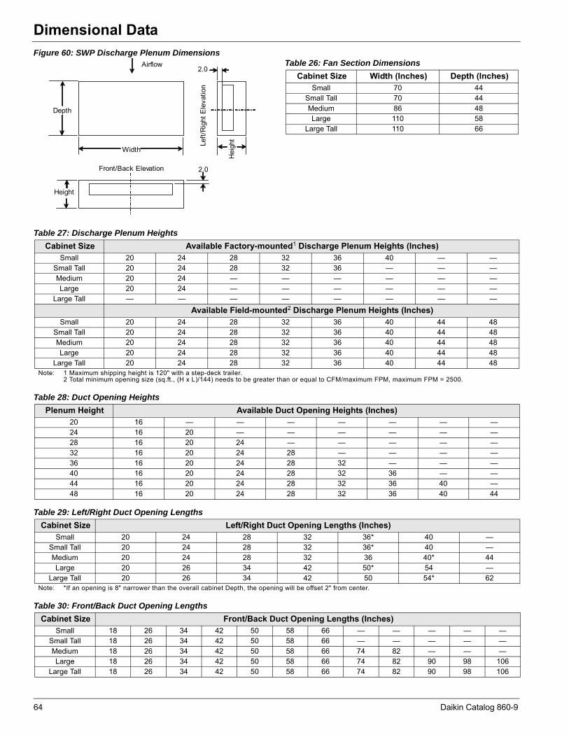
Dimensional Data
Figure 60: SWP Discharge Plenum DimensionsAirflow
Width
Depth
Height
Hei
ght
2.0
2.0
Front/Back Elevation
Left/
Rig
ht E
leva
tion
Table 26: Fan Section Dimensions
Cabinet Size Width (Inches) Depth (Inches)Small 70 44
Small Tall 70 44Medium 86 48Large 110 58
Large Tall 110 66
Table 27: Discharge Plenum Heights
Cabinet Size Available Factory-mounted1 Discharge Plenum Heights (Inches)Small 20 24 28 32 36 40 — —
Small Tall 20 24 28 32 36 — — —Medium 20 24 — — — — — —Large 20 24 — — — — — —
Large Tall — — — — — — — —Available Field-mounted2 Discharge Plenum Heights (Inches)
Small 20 24 28 32 36 40 44 48Small Tall 20 24 28 32 36 40 44 48Medium 20 24 28 32 36 40 44 48Large 20 24 28 32 36 40 44 48
Large Tall 20 24 28 32 36 40 44 48Note: 1 Maximum shipping height is 120" with a step-deck trailer.
2 Total minimum opening size (sq.ft., (H x L)/144) needs to be greater than or equal to CFM/maximum FPM, maximum FPM = 2500.
Table 28: Duct Opening Heights
Plenum Height Available Duct Opening Heights (Inches)20 16 — — — — — — —24 16 20 — — — — — —28 16 20 24 — — — — —32 16 20 24 28 — — — —36 16 20 24 28 32 — — —40 16 20 24 28 32 36 — —44 16 20 24 28 32 36 40 —48 16 20 24 28 32 36 40 44
Table 29: Left/Right Duct Opening Lengths
Cabinet Size Left/Right Duct Opening Lengths (Inches)Small 20 24 28 32 36* 40 —
Small Tall 20 24 28 32 36* 40 —Medium 20 24 28 32 36 40* 44Large 20 26 34 42 50* 54 —
Large Tall 20 26 34 42 50 54* 62Note: *If an opening is 8" narrower than the overall cabinet Depth, the opening will be offset 2" from center.
Table 30: Front/Back Duct Opening Lengths
Cabinet Size Front/Back Duct Opening Lengths (Inches)Small 18 26 34 42 50 58 66 — — — — —
Small Tall 18 26 34 42 50 58 66 — — — — —Medium 18 26 34 42 50 58 66 74 82 — — —Large 18 26 34 42 50 58 66 74 82 90 98 106
Large Tall 18 26 34 42 50 58 66 74 82 90 98 106
64 Daikin Catalog 860-9
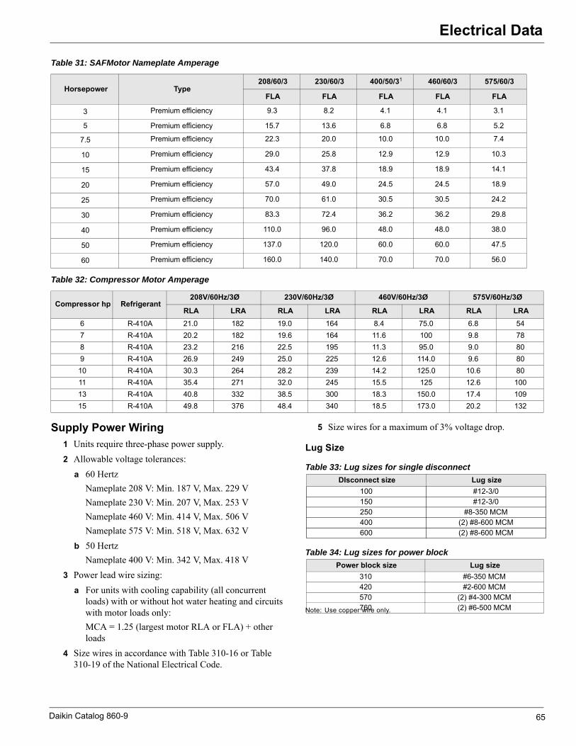
Electrical Data
Electrical DataTable 31: SAFMotor Nameplate Amperage
Table 32: Compressor Motor Amperage
Supply Power Wiring1 Units require three-phase power supply.2 Allowable voltage tolerances:
a 60 HertzNameplate 208 V: Min. 187 V, Max. 229 VNameplate 230 V: Min. 207 V, Max. 253 VNameplate 460 V: Min. 414 V, Max. 506 VNameplate 575 V: Min. 518 V, Max. 632 V
b 50 HertzNameplate 400 V: Min. 342 V, Max. 418 V
3 Power lead wire sizing:a For units with cooling capability (all concurrent
loads) with or without hot water heating and circuits with motor loads only:MCA = 1.25 (largest motor RLA or FLA) + other loads
4 Size wires in accordance with Table 310-16 or Table 310-19 of the National Electrical Code.
5 Size wires for a maximum of 3% voltage drop.
Lug Size
Note: Use copper wire only.
Horsepower Type208/60/3 230/60/3 400/50/31 460/60/3 575/60/3
FLA FLA FLA FLA FLA
3 Premium efficiency 9.3 8.2 4.1 4.1 3.1
5 Premium efficiency 15.7 13.6 6.8 6.8 5.2
7.5 Premium efficiency 22.3 20.0 10.0 10.0 7.4
10 Premium efficiency 29.0 25.8 12.9 12.9 10.3
15 Premium efficiency 43.4 37.8 18.9 18.9 14.1
20 Premium efficiency 57.0 49.0 24.5 24.5 18.9
25 Premium efficiency 70.0 61.0 30.5 30.5 24.2
30 Premium efficiency 83.3 72.4 36.2 36.2 29.8
40 Premium efficiency 110.0 96.0 48.0 48.0 38.0
50 Premium efficiency 137.0 120.0 60.0 60.0 47.5
60 Premium efficiency 160.0 140.0 70.0 70.0 56.0
Compressor hp Refrigerant208V/60Hz/3Ø 230V/60Hz/3Ø 460V/60Hz/3Ø 575V/60Hz/3Ø
RLA LRA RLA LRA RLA LRA RLA LRA6 R-410A 21.0 182 19.0 164 8.4 75.0 6.8 547 R-410A 20.2 182 19.6 164 11.6 100 9.8 788 R-410A 23.2 216 22.5 195 11.3 95.0 9.0 809 R-410A 26.9 249 25.0 225 12.6 114.0 9.6 8010 R-410A 30.3 264 28.2 239 14.2 125.0 10.6 8011 R-410A 35.4 271 32.0 245 15.5 125 12.6 10013 R-410A 40.8 332 38.5 300 18.3 150.0 17.4 10915 R-410A 49.8 376 48.4 340 18.5 173.0 20.2 132
Table 33: Lug sizes for single disconnect
DIsconnect size Lug size100 #12-3/0150 #12-3/0250 #8-350 MCM400 (2) #8-600 MCM600 (2) #8-600 MCM
Table 34: Lug sizes for power block
Power block size Lug size310 #6-350 MCM420 #2-600 MCM570 (2) #4-300 MCM760 (2) #6-500 MCM
Daikin Catalog 860-9 65

Unit Weights
Unit WeightsTable 35: Unit and Component Weights for Small and Small Tall Cabinets
Component DescriptionSmall Cabinet Small Tall Cabinet
Unit Model Size023 028 033 039 044 050
Basic Cabinet1 3587 3637 3651 3994 4008 4008Cooling Coil Section–Drain Pan Only 1045 1081
Supply Fan/Control Panel Section 1061 993Condenser/Compressor Section 1480 1530 1544 1920 1934 1934
Condenser Water Weight 29 31 35 44 47 50Face Load Filter Rack
Rack Only 64 672"—MERV 7 15 164"—MERV 8 15 164"—MERV 11 62 634"—MERV 13 62 634"—MERV 14 62 63
Evaporator Coils5 row–12 fpi 372 N/A
Large 5 row–12 fpi N/A 440Waterside Economizer Coils
Large 4 row–12 fpi 316 371Water Weight 117 152
Electric Heat34 kW 20 20
Supply Fan Assembly13" SWSI 106 N/A15" SWSI 110 N/A16" SWSI 122 N/A18" SWSI 181 18120" SWSI 195 19522" SWSI 245 24524" SWSI 267 26727" SWSI N/A 395
Supply Fan Motor–ODP3 HP 76 765 HP 88 88
7.5 HP 134 13410 HP 158 15815 HP 203 20320 HP 235 235
Supply Fan Motor–TEFC3 HP 77 775 HP 91 91
7.5 HP 150 15010 HP 184 18415 HP 253 25320 HP 321 321
Variable Frequency Drive3 HP 14 145 HP 14 14
7.5 HP 20 2010 HP 20 2015 HP 35 3520 HP 35 35
Discharge Plenum32" High without Sound Baffles 268
32" High with Sound Baffles 428Note: 1 Basic unit consists of a cooling coil section without coils, a supply fan/control panel section without supply fans, supply fan motors or VFD and a
condenser/compressor section.
66 Daikin Catalog 860-9

Unit Weights
Table 36: Unit and Component Weights for Medium and Large Cabinets
Component DescriptionMedium Cabinet Large Cabinet
Unit Model Size044 050 056 062 065 062 073 080 088
Basic Cabinet1 4733 4747 5136 5136 5136 6179 8507 8563 8619Cooling Coil Section–Drain Pan Only 1288 1542
Supply Fan/Control Panel Section 1377 1853Condenser/Compressor Section 2067 2081 2470 2470 2470 2784 3506 3534 3562
Condenser Water Weight 52 55 61 64 68 67 85 88 91Face Load Filter Rack
Rack Only 95 1162"—MERV 7 22 274"—MERV 8 22 274"—MERV 11 91 1124"—MERV 13 91 1134"—MERV 14 91 113
Evaporator CoilsLarge 5 row–12 fpi 668 776 — — —
Standard 6 row—12 fpi N/A — 776 776 776Waterside Economizer Coils
Large 4 row–12 fpi 557 654Water Weight 250 279
Electric Heat34 kW 20 2068 kW 40 40
Supply Fan Assembly18" SWSI 181 N/A20" SWSI 195 N/A22" SWSI 245 24524" SWSI 267 26727" SWSI 395 39530" SWSI 434 43433" SWSI 592 59236" SWSI 723 723
Supply Fan Motor–ODP15 HP 203 N/A20 HP 235 N/A25 HP 290 29030 HP 336 33640 HP 434 43450 HP N/A 723
Supply Fan Motor–TEFC15 HP 253 N/A20 HP 321 N/A25 HP 354 35430 HP 416 41640 HP 538 53850 HP N/A 612
Variable Frequency Drive15 HP 35 N/A20 HP 35 N/A25 HP 53 5330 HP 53 5340 HP 53 5350 HP N/A 152
Discharge Plenum32" High without Sound Baffles 320 416
32" High with Sound Baffles 516 680Note: 1 Basic unit consists of a cooling coil section without coils, a supply fan/control panel section without supply fans, supply fan motors or
VFD and a condenser/compressor section.
Daikin Catalog 860-9 67
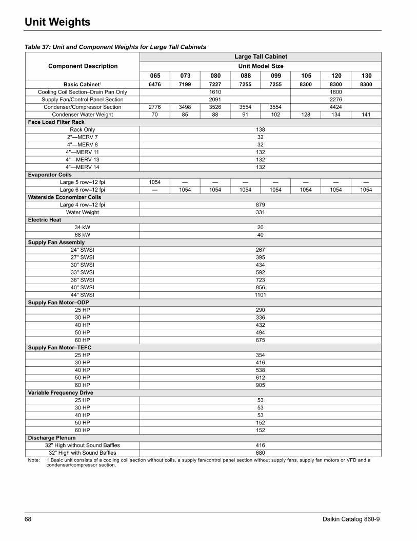
Unit Weights
Table 37: Unit and Component Weights for Large Tall Cabinets
Component DescriptionLarge Tall Cabinet
Unit Model Size065 073 080 088 099 105 120 130
Basic Cabinet1 6476 7199 7227 7255 7255 8300 8300 8300Cooling Coil Section–Drain Pan Only 1610 1600
Supply Fan/Control Panel Section 2091 2276Condenser/Compressor Section 2776 3498 3526 3554 3554 4424
Condenser Water Weight 70 85 88 91 102 128 134 141Face Load Filter Rack
Rack Only 1382"—MERV 7 324"—MERV 8 324"—MERV 11 1324"—MERV 13 1324"—MERV 14 132
Evaporator CoilsLarge 5 row–12 fpi 1054 — — — — — — —Large 6 row–12 fpi — 1054 1054 1054 1054 1054 1054 1054
Waterside Economizer CoilsLarge 4 row–12 fpi 879
Water Weight 331Electric Heat
34 kW 2068 kW 40
Supply Fan Assembly24" SWSI 26727" SWSI 39530" SWSI 43433" SWSI 59236" SWSI 72340" SWSI 85644" SWSI 1101
Supply Fan Motor–ODP25 HP 29030 HP 33640 HP 43250 HP 49460 HP 675
Supply Fan Motor–TEFC25 HP 35430 HP 41640 HP 53850 HP 61260 HP 905
Variable Frequency Drive25 HP 5330 HP 5340 HP 5350 HP 15260 HP 152
Discharge Plenum32" High without Sound Baffles 416
32" High with Sound Baffles 680Note: 1 Basic unit consists of a cooling coil section without coils, a supply fan/control panel section without supply fans, supply fan motors or VFD and a
condenser/compressor section.
68 Daikin Catalog 860-9

© 2013 Daikin Applied Applied • www.DaikinApplied.com • 800-432-1342 11/11
Daikin Training and Development
Now that you have made an investment in modern, efficient Daikin equipment, its care should be a high priority. Fortraining information on all Daikin HVAC products, please visit us at www.DaikinApplied.com and click on training, or call 540-248-9646 and ask for the Training Department.
Warranty
All Daikin equipment is sold pursuant to its standard terms and conditions of sale, including Limited Product Warranty. Consult your local Daikin Representative for warranty details. Refer to Form 933-430285Y. To find your local Daikin Representative, go to www.DaikinApplied.com.
Aftermarket Services
To find your local parts office, visit www.DaikinApplied.com or call 800-37PARTS (800-377-2787). To find your local service office, visit www.DaikinApplied.com or call 800-432-1342.
This document contains the most current product information as of this printing. For the most up-to-date product information, please go to www.DaikinApplied.com.
Products manufactured in an ISO certified facility.


