� Introduction� Functional Requirements� General Solution� Detailed Design� Summary
Presentation OverviewPresentation Overview
IntroductionIntroduction
� Self-guided wheelchair• Capable of autonomously moving through
environment while avoiding any obstacles• Selectable starting points/final destinations• Based on motorized wheelchair• Programmed with LabVIEW Embedded 8.2• Sponsored by National Instruments
Project DescriptionProject Description
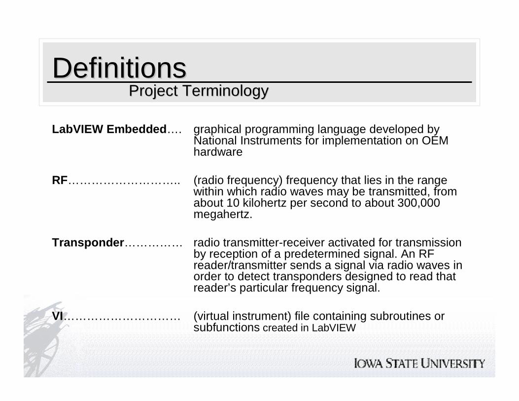
DefinitionsDefinitions
LabVIEW Embedded…. graphical programming language developed by National Instruments for implementation on OEM hardware
RF……………………….. (radio frequency) frequency that lies in the range within which radio waves may be transmitted, from about 10 kilohertz per second to about 300,000 megahertz.
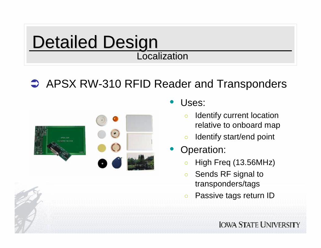
Transponder…………… radio transmitter-receiver activated for transmission by reception of a predetermined signal. An RF reader/transmitter sends a signal via radio waves in order to detect transponders designed to read that reader’s particular frequency signal.
VI………………………… (virtual instrument) file containing subroutines or subfunctions created in LabVIEW
Project TerminologyProject Terminology
Functional RequirementsFunctional Requirements
� Medical hospital setting� Operation on a single floor level� Free of stairs or similar large drop-offs� Common hospital floor type
• Tile• Hardwood• Short carpet
Operating EnvironmentOperating Environment
Functional RequirementsFunctional Requirements
� Primary User• Provides location information for the system input• Shape recognition and basic literacy• Medical staff or guardian
� Secondary User• Passenger that will be transported • Able to maintain a seated position within the
confines of the chair dimensions• Patient
Intended Users and UsesIntended Users and Uses
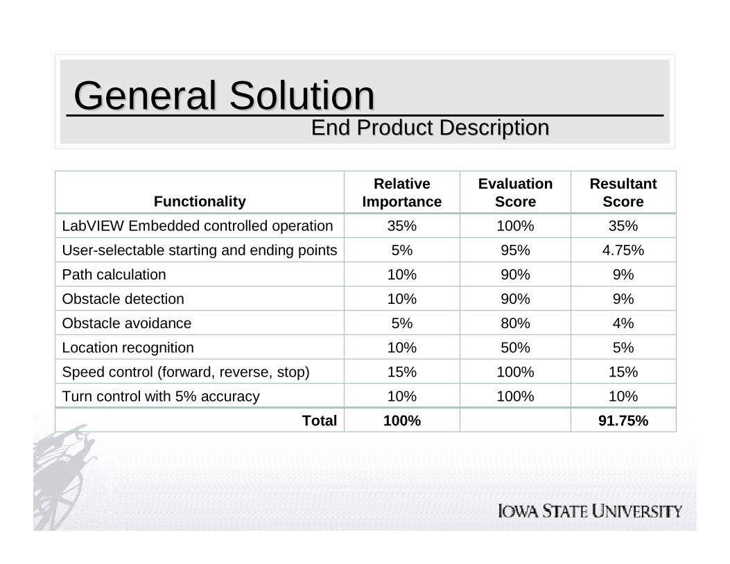
General SolutionGeneral SolutionEnd Product DescriptionEnd Product Description
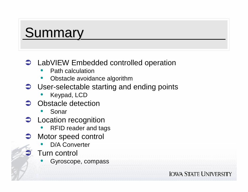
9%90%10%Path calculation
9%90%10%Obstacle detection
35%100%35%LabVIEW Embedded controlled operation
4.75%95%5%User-selectable starting and ending points
91.75%100%Total
100%
100%
50%
80%
Evaluation Score
10%
15%
5%
4%
Resultant Score
10%Turn control with 5% accuracy
15%Speed control (forward, reverse, stop)
10%Location recognition
5%Obstacle avoidance
Relative ImportanceFunctionality
General SolutionGeneral SolutionEnd Product DescriptionEnd Product Description
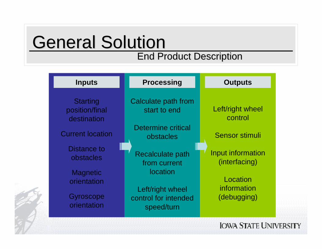
Inputs Processing Outputs
Starting position/final destination
Current location
Distance to obstacles
Magnetic orientation
Gyroscope orientation
Calculate path from start to end
Determine critical obstacles
Recalculate path from current
location
Left/right wheel control for intended
speed/turn
Left/right wheel control
Sensor stimuli
Input information (interfacing)
Location information (debugging)
General SolutionGeneral SolutionEnd Product DescriptionEnd Product Description
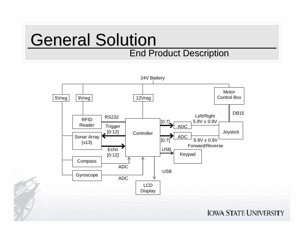
[0:7]
12Vreg
24V Battery
Joystick
Left/Right5.9V ± 0.9V
5.9V ± 0.9VForward/Reverse
[0:7]ADC
ADC
DB15
Motor Control Box
RS232
Controller
RFIDReader
Gyroscope
Compass
Sonar Array(x13)
Echo[0:12]
9Vreg5Vreg
Trigger[0:12]
LCDDisplay
USB
USB Keypad
ADC
ADC
General SolutionGeneral SolutionEnd Product DescriptionEnd Product Description
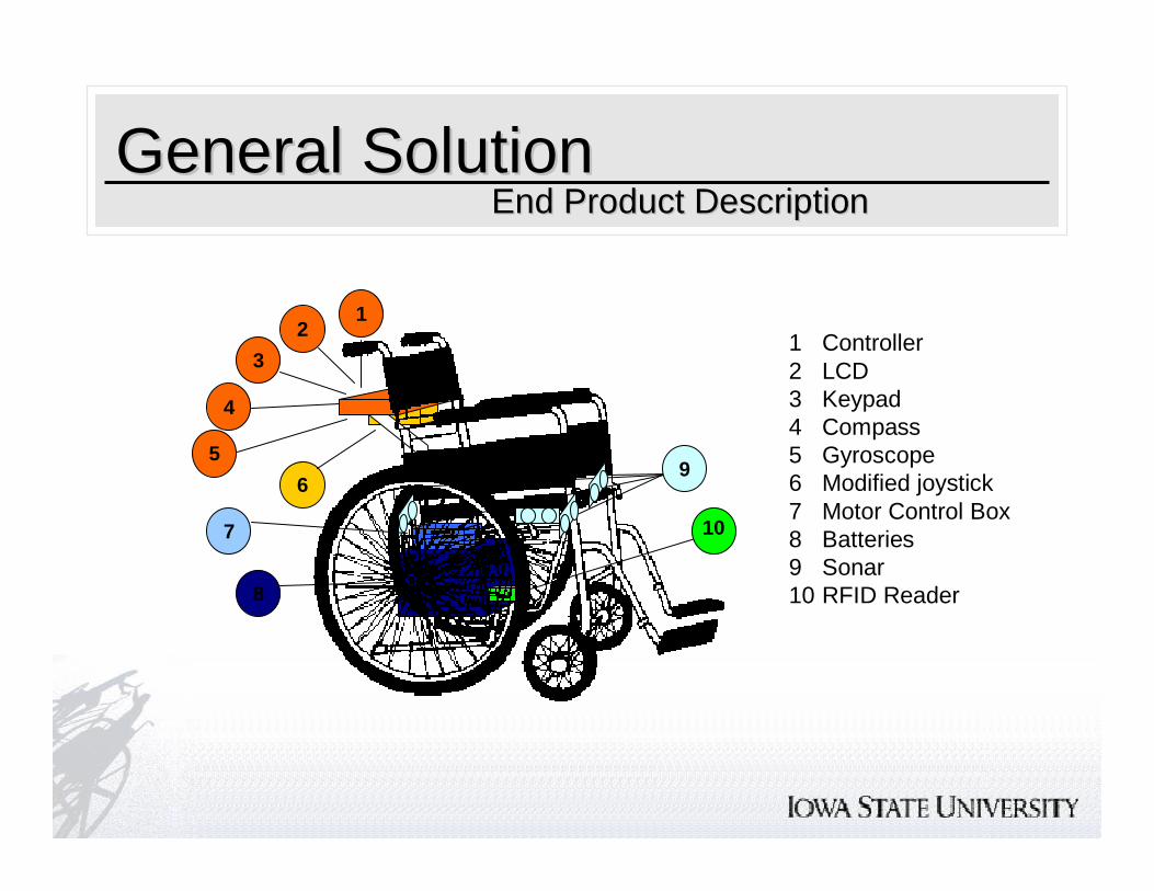
1 Controller2 LCD3 Keypad4 Compass5 Gyroscope6 Modified joystick7 Motor Control Box8 Batteries9 Sonar10 RFID Reader
12
3
4
59
7
8
10
6
Detailed DesignDetailed Design
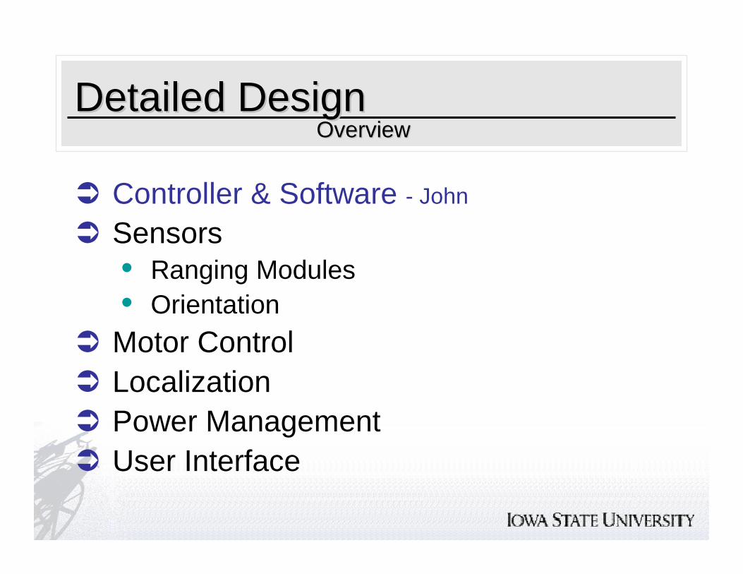
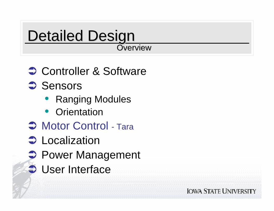
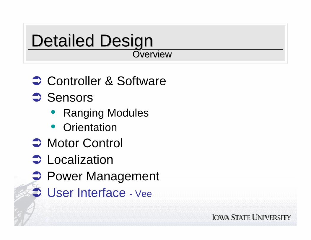
� Controller & Software - John
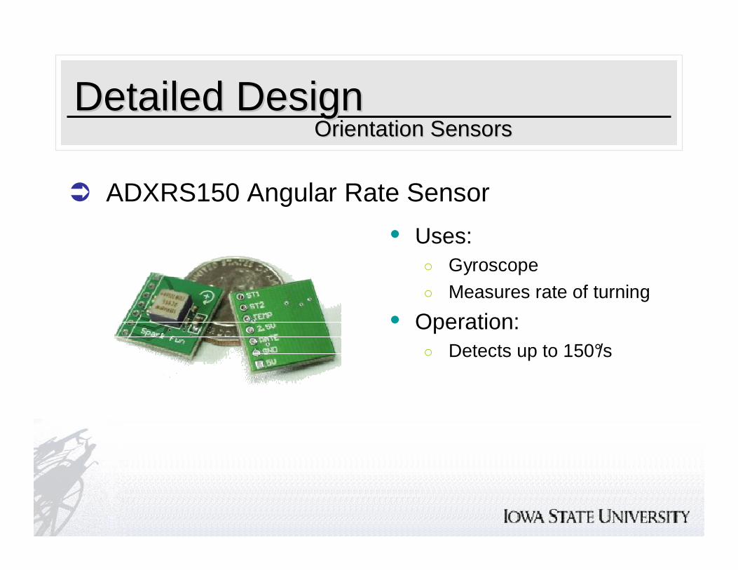
� Sensors• Ranging Modules• Orientation
� Motor Control� Localization� Power Management� User Interface
OverviewOverview
Detailed DesignDetailed Design
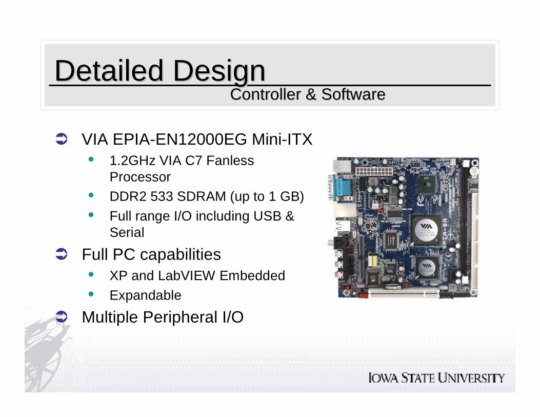
� VIA EPIA-EN12000EG Mini-ITX• 1.2GHz VIA C7 Fanless
Processor• DDR2 533 SDRAM (up to 1 GB)
• Full range I/O including USB & Serial
� Full PC capabilities• XP and LabVIEW Embedded
• Expandable
� Multiple Peripheral I/O
Controller & SoftwareController & Software
Detailed DesignDetailed Design
� Operating System• Windows XP Embedded
○ RFID Reader
� Software• LabVIEW Embedded
○ All calculations, algorithms○ VIs for I/O to sensors