15
Self-lubricated Linear Bearing 8

Self-lubricatedLinear Bearing
8
8.1 Characteristics
(2) Interchangeability
(4) High impact capability
(6) High load capacity
(8) Reliable
(10) Substitutability
(12) Wide range of applications
134
(1) Excellent Wear Resistance
Unlike linear ball bearing that requires running on high hardness heat treated shaft (SUJ2), Self-Lubricated Linear Bearing can be used with Hard Chrome Plated Shaft (S45C). Under correct use, the life expectancy is much higher than linear ball bearings.
Suitable for either linear, rotary, or combination of both motions.
Lubrications are not required; however, the use of adequate lubrications can minimize frictions and wear
Great resistance to corrosion allows the bearing to be operating or submerging in alcohol, gaso-line, water, oil and stand up to harsh environment.
Low coefficient of friction eliminates oscillating, which is suitable for continuous and intermittent motions.
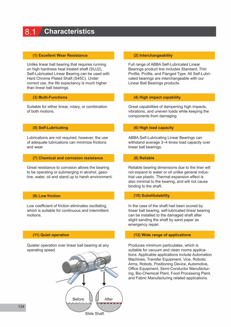
Quieter operation over linear ball bearing at any operating speed.
Full range of ABBA Self-Lubricated Linear Bearings product line includes Standard, Thin Profile, Profile, and Flanged Type. All Self-Lubri-cated bearings are interchangeable with our Linear Ball Bearings products.
Great capabilities of dampening high impacts, vibrations, and uneven loads while keeping the components from damaging.
ABBA Self-Lubricating Linear Bearings can withstand average 3~4 times load capacity over linear ball bearings.
(3) Multi-Functions
(5) Self-Lubricating
(7) Chemical and corrosion resistance
(9) Low friction
(11) Quiet operation
Reliable bearing dimensions due to the liner will not expand to water or oil unlike general indus-trial use plastic. Thermal expansion effect is also minimal to the bearing, and will not cause binding to the shaft.
In the case of the shaft had been scored by linear ball bearing, self-lubricated linear bearing can be installed to the damaged shaft after slight sanding the shaft by sand paper as emergency repair.
Produces minimum particulates, which is suitable for vacuum and clean rooms applica-tions. Applicable applications include Automation Machines, Transfer Equipment, Vice, Robotic Arms, Robots, Positioning Device, Automotive, Office Equipment, Semi-Conductor Manufactur-ing, Bio-Chemical Plant, Food Processing Plant, and Fabric Manufacturing related applications.
Before After
Slide Shaft

8.2 Structure
8.3 Size selection
Formula
• Maximum load = L / N x F• Load x Velocity = L / N x V x F• Axial Driving Force = µ x LL : Total Load Capacity (kgf)N : Number of BearingsF : Safety Factor 2~3V : Velocity (m/sec)µ : Fricition Factor : 0.15~0.25
Example 1
Where
L = 100 kgf, N = 4, assumeF = 2.5, µ = 0.2, V=0.6 m/sec• Maximum load = L / N x F = 100 / 4 x 2.5 = 62.5 kgf• Load x Velocity = L / N x V x F = 100 / 4 x 0.6 x 2.5= 37.5 kgf · m/sec• Required Driving force = µ x L = 0.2 x 100 = 20 kgf
Cross reference the results to dimension chart, known TM 25 Bearing (Max. Load = 1000 kgf, Max. Load x Velocity = 52.8 kgf · m/sec) is capable of this application.
• Load x Velocity = L / N x V x F = 100 / 4 x 1.0 x 2.5= 62.5 kgf · m/sec
135
Stan
dard
Ball
Cag
edM
inia
ture
Cam
Rol
ler
Rou
nd S
haft
Line
ar G
uide
Bal
l Scr
ewO
ther
com
pone
nts
Ball
Scre
wSu
ppor
t Uni
tSe
lf-lu
bric
ated
Lin
ear B
earin
g
1. Anodized aluminum, 6060 T62.Water-proof Bonding Agent3.Frelon thickness: 0.5mm
The composition of super wear-resistant sliding plate isTeflon + Glass fiber + Metal powder + Special formula, which are imported high-tech materials, generally used in the wear-resistant rails of the million-level precision machine tool, it can slide uppon high load for a long time without abrasion. Its wear-resistant function is better than General DU bearings.
Use the formula below to calculate Maximum PV Value ( Load x Velocity), then multiply its value by Safety Factor. Cross reference the value to dimension chart in our catalogue page to select bearing size. The size of bearing is propotional to the load and Velocity.
Example 2
Assuming a sliding platform has a load of 100kg, uses 4 bearings, and velocity is 0.6 m/sec. Cacula-tion of bearing size and required axial driving force is shown below.
Assuming all values remains unchanged, except velocity increases to 1.0 m/sec. Calculation of bearing size is shown below.
Where
According to the dimension chart, TM30 bearing (Max · Load x Velocity =68.7 kgf · m/sec is capable of this application.

8.4 Life calculation
Formula
Example 3
Where
From dimension chart known
136
Bearing’s Life Calculation is based on Maximum allowable amount of wear. Once this value has been decided, bearing’s life can be calculated by using the formula below. Under constant load and velocity, bearing’s life is proportional to bearing inner diameter.
T : Sliding time (hour)K : Wearing rate : 1 x 10V : Velocity (m/min)P : Pressure (kgf/cm )
W : Amount of Wear (mm)A : Bearing inner diameter (cm) I : Bearing length (cm)L : Total load (kgf)N : Number of Bearings
-7
2
To calculate the life of TM25 bearing from example 1.
W = 0.05mm, K = 1 x 10 , A = 2.5-7
-7
hoursUsage per day = 6 x 300 x 8 / 3600 = 4 hoursTotal life time = 8218 / 4 = 2054 days
Note:Allowable amount of wear is proportional to bearing’s life. For example, if allowable amout of wear = 0.01mm, Bearing’s life = 4108 days.

8.5 Cantilevered loads
Example
Formula
Example
137
Stan
dard
Ball
Cag
edM
inia
ture
Cam
Rol
ler
Rou
nd S
haft
Line
ar G
uide
Bal
l Scr
ewO
ther
com
pone
nts
Ball
Scre
wSu
ppor
t Uni
tSe
lf-lu
bric
ated
Lin
ear B
earin
g
Example
Caution
When distance X equals to 100mm, minimum bearing separation Y must be at least 50mm.
• Binding of the bearing can occur when the ratio exceeds 2:1• Adequate lubrications will help reduce friction and helps increase the 2:1 ratio
In the case of holding more than 2:1 ratio, method of using counter weight could be use to prevent binding. Use the formula shown below.
M : Mass of loadX : Distance from load to the shaftW : Mass of counter weightZ : 1.5 x (Y)
When W is calculated, load per bearing can be calculated.M + W / # of bearings
If the ratio of the cantilever installation is greater than 2: 1, a counterweight method can be used to avoid bearing binding.
Bearing

8.6 Open type bearing mounting configurations
138
Load capacities on open type self-lubricated linear bearings will depending on their mounting configurations.
Example
SM series bearing installed on the plate, and secured by two retaining rings.
SM series bearing installed in the bore, and secured by two retaining rings.
SM series bearing installed in the bore, and secured by one retaining ring.

139
Stan
dard
Ball
Cag
edM
inia
ture
Cam
Rol
ler
Rou
nd S
haft
Line
ar G
uide
Bal
l Scr
ewO
ther
com
pone
nts
Ball
Scre
wSu
ppor
t Uni
tSe
lf-lu
bric
ated
Lin
ear B
earin
g
SM series bearing secured by two push plates.
SM series bearing installed by a retaining ring; a push plate is pressed against the ring to secure the bearing.
When using SCM series pillow block bearing, bolts can be installed either from top or below.
Flanged type bearing bolted onto the plate; adjust the parallelism to other bearings via lashes given in the bolt hole on the flange.

SM Standard type self-lubricated linear bearingSMP Open type self-lubricated linear bearing
8.7 Round profile type
Ordering key : SM 201 2
1
2 Bearing inner diameter
Model No.
Standard type Open typeInner Dia. Dimensions
140
Unit : mm
SM Standard type
SMP Open type

Max. Static load Max. PV Max. Speed Weight (g)Model No.
Standard type Open type
Unit : mm
141
Stan
dard
Ball
Cag
edM
inia
ture
Cam
Rol
ler
Rou
nd S
haft
Line
ar G
uide
Bal
l Scr
ewO
ther
com
pone
nts
Ball
Scre
wSu
ppor
t Uni
tSe
lf-lu
bric
ated
Lin
ear B
earin
g

SMT thin profile self-lubricated linear bearing
8.8 SMT Thin profile type
Ordering key : SMT 201 2
1
2 Bearing inner diameter
Max Speed Weight
142
Unit : mm
Model No. Inner Dia. Dimensions Max. PVMax. Static load

8.9 SMK Square flange type
SMK Square flange self-lubricated bearing
Ordering key : SMK 201 2
1
2 Bearing inner diameter
143
Unit : mm
Model No. Inner Dia. Dimensions
Max. Static load Max. PV Max. Speed Weight Model No.
Stan
dard
Ball
Cag
edM
inia
ture
Cam
Rol
ler
Rou
nd S
haft
Line
ar G
uide
Bal
l Scr
ewO
ther
com
pone
nts
Ball
Scre
wSu
ppor
t Uni
tSe
lf-lu
bric
ated
Lin
ear B
earin
g

8.10 SMF Round flange type
SMF Round flange self-lubricated bearing
Ordering key : SMF 201 2
1
2 Bearing inner diameter
144
Unit : mm
Model No.Inner Dia. Dimensions
Max. Static load Max. PV Max. Speed Weight Model No.

8.11 SMFD Center flange type
SMFD Center flange self-lubricated bearing
Ordering key : SMFD 201 2
1
2 Bearing inner diameter
145
Stan
dard
Ball
Cag
edM
inia
ture
Cam
Rol
ler
Rou
nd S
haft
Line
ar G
uide
Bal
l Scr
ewO
ther
com
pone
nts
Ball
Scre
wSu
ppor
t Uni
tSe
lf-lu
bric
ated
Lin
ear B
earin
g
Unit : mm
Model No.Inner Dia. Dimensions
Max. Static load Max. PV Max. Speed Weight Model No.

SMK-L Long type round flange self-lubricated bearing
8.12 SMK-L Long square flange type
Ordering key : SMK-L 201 2
1
2 Bearing inner diameter
146
Unit : mm
Model No.Inner Dia. Dimensions
Max. Static load Max. PV Max. Speed Weight Model No.

8.13 SMF-L Long round flange type
SMF-L Long type round flange self-lubricated bearing
Ordering key : SMF-L 201 2
1
2 Bearing inner diameter
147
Unit : mm
Stan
dard
Ball
Cag
edM
inia
ture
Cam
Rol
ler
Rou
nd S
haft
Line
ar G
uide
Bal
l Scr
ewO
ther
com
pone
nts
Ball
Scre
wSu
ppor
t Uni
tSe
lf-lu
bric
ated
Lin
ear B
earin
g
Model No.Inner Dia. Dimensions
Max. Static load Max. PV Max. Speed Weight Model No.


![G99LE15-040 I Linear Guideway - Servo Vision1].pdf · II G99LE15-0408 (The specifications in this catalogue are subject to change without notification.) 4. Intelligent Linear Guideway](https://static.documents.pub/doc/80x56/5cfcb28988c9931b0e8c5907/g99le15-040-i-linear-guideway-servo-1pdf-ii-g99le15-0408-the-specifications.jpg)


