Page 1
Title:
Self-Organising Network Management for
Heterogeneous LTE-Advanced Networks
A thesis submitted in fulfilment of the requirements for the degree of
Doctor of Philosophy (PhD) in Electronic and Computer Engineering
By:
Mohammadreza Behjati
Supervisors:
Prof. John Cosmas
Dr. Rajagopal Nilavalan
March 2015
Page 2
ii
Abstract
Since 2004, when the Long Term Evolution (LTE) was first proposed to be
publicly available in the year 2009, a plethora of new characteristics, techniques
and applications have been constantly enhancing it since its first release, over the
past decade. As a result, the research aims for LTE-Advanced (LTE-A) have been
released to create a ubiquitous and supportive network for mobile users. The
incorporation of heterogeneous networks (HetNets) has been proposed as one of
the main enhancements of LTE-A systems over the existing LTE releases, by
proposing the deployment of small-cell applications, such as femtocells, to
provide more coverage and quality of service (QoS) within the network, whilst
also reducing capital expenditure. These principal advantages can be obtained at
the cost of new challenges such as inter-cell interference, which occurs when
different network applications share the same frequency channel in the network.
In this thesis, the main challenges of HetNets in LTE-A platform have been
addressed and novel solutions are proposed by using self-organising network
(SON) management approaches, which allows the cooperative cellular systems to
observe, decide and amend their ongoing operation based on network conditions.
The novel SON algorithms are modelled and simulated in OPNET modeler
simulation software for the three processes of resource allocation, mobility
management and interference coordination in multi-tier macro-femto networks.
Different channel allocation methods based on cooperative transmission,
frequency reuse and dynamic spectrum access are investigated and a novel SON
sub-channel allocation method is proposed based on hybrid fractional frequency
reuse (HFFR) scheme to provide dynamic resource allocation between macrocells
and femtocells, while avoiding co-tier and cross-tier interference. Mobility
management is also addressed as another important issue in HetNets, especially in
hand-ins from macrocell to femtocell base stations. The existing research
considers a limited number of methods for handover optimisation, such as signal
strength and call admission control (CAC) to avoid unnecessary handovers, while
our novel SON handover management method implements a comprehensive
algorithm that performs sensing process, as well as resource availability and user
residence checks to initiate the handover process at the optimal time. In addition
to this, the novel femto over macro priority (FoMP) check in this process also
gives the femtocell target nodes priority over the congested macrocells in order to
improve the QoS at both the network tiers. Inter-cell interference, as the key
challenge of HetNets, is also investigated by research on the existing time-
domain, frequency-domain and power control methods. A novel SON interference
mitigation algorithm is proposed, which is based on enhanced inter-cell
interference coordination (eICIC) with power control process. The 3-phase power
control algorithm contains signal to interference plus noise ratio (SINR)
measurements, channel quality indicator (CQI) mapping and transmission power
amendments to avoid the occurrence of interference due to the effects of high
transmission power.
The results of this research confirm that if heterogeneous systems are backed-up
with SON management strategies, not only can improve the network capacity and
QoS, but also the new network challenges such as inter-cell interference can also
be mitigated in new releases of LTE-A network.
Page 3
iii
Acknowledgements
The greatest adorations to God, not only because of his permanent support
through my entire life, but moreover because he is worthy of worship and praise.
I would like to express my appreciation to my PhD supervisor Prof. John Cosmas
for his continuous helps and encouragement and the members of WNCC centre at
Brunel University London, my second supervisor Dr. Rajagopal Nilavalan, also
Prof. Hamed Al-Raweshidy and Dr. Thomas Owens for their valuable advises
during my research.
I would like to also acknowledge my dear colleagues, relatives and friends, Dr.
Giuseppe Araniti, Dr. Hossein Madani Kermani, Dr. Pavlos Lazaridis, Dr. Farhad
Komeyli Birjandi, Prof. Farkhondeh Behjati, Dr. Yue Zhang, Mr. Hooshang
Kaveh, Mr. Shahab Kaveh, Dr. Seyed Reza Abdollahi, Dr. Massimo Condoluci,
Mr. Amirsam Jamilazari, Dr. Zaharias Zaharis, Dr. Rafiq Swash, Dr. Mohammad
Reza Herfatmanesh, Dr. Mansour Salehi Moghadam, Mr. Keith Withers, Dr.
Morad Daneshvar, Mr. Ahmad Nasrollahi, Dr. Roohollah Haghpanahan, Dr.
Behnood Afshari, Dr. Amir Hooshang Raeisi, Dr. Paolo Coppo, Dr. Mohsen
Alamuti, Mr. Mohammad Imanieh, Dr. Mona Mortazian, Dr. Kamran Pedram,
Mr. Ali Zanganeh, Dr. Aysan Ghaemian, Mr. Arash Rezvani, Dr. Ehsan Hosseini,
Mr. Mohammad Piri Ardakani, Dr. Armin Kashefi, Mr. Ehsan Faghani, Dr.
Mehran Sadeghi, Mrs. Sheida Saadati, Dr. Reza Naji, Dr. Parastoo Ghalamchi,
Dr. Reza Abbaszadeh, Mr. Mehrzad Khodapanah, Dr. Arjang Amini, Mr. Kasra
Ahmadi, Dr. Amir Salimi and Mr. Saeed Ahrabi.
Special thanks to my beloved fiancée Saba for her moral support whilst I was far
away from her during the years of my study.
Finally, my deepest gratitude goes to my parents, Mr. Aman Behjati (M.Eng.) and
Mrs. Shahla Kaveh for their prayers and infinite support in every single aspect of
my life. Words are unable to express how I am indebted to them in my life.
Page 4
iv
Dedication
Dedicated to my Mother, Father and Fiancée.
Page 5
v
Publications and Presentations
Publications
Journals
1. M. Behjati, J. P. Cosmas, R. Nilavalan, G. Araniti, and M. Condoluci, "Self-
Organizing Comprehensive Handover Strategy for Multi-Tier Heterogeneous
LTE-Advanced Networks," IET Journal of Science, Measurement and
Technology, Special Issue on Green Wireless Internet Technology, vol. 8, no. 6,
November 2014, pp. 441 – 451.
2. G. Araniti, M. Condoluci, A. Iera, A. Molinaro, J. Cosmas, and M. Behjati, "A
Low-Complexity Resource Allocation Algorithm for Multicast Service Delivery
in OFDMA Networks," IEEE Transactions on Broadcasting, vol. 60, no. 2, May
2014, pp. 358 – 369.
Conferences
1. M. Behjati, and J. Cosmas, "Self-Organizing Interference Coordination for
Future LTE-Advanced Network QoS Improvements," IEEE International
Symposium on Broadband Multimedia Systems and Broadcasting (BMSB),
Beijing, China, pp. 1 – 6, June 2014.
2. M. Behjati, and J. Cosmas, “Multi-Layer Cell Deployment Strategy for Self-
Organizing LTE-Advanced Networks,” IEEE International Wireless
Communications and Mobile Computing Conference (IWCMC), Cagliari, Italy,
pp. 820 – 825, July 2013.
3. M. Behjati, J. Cosmas, and R. Nilavalan, “Hierarchical Self-Organizing
Strategy in LTE-Advanced Networks,” 6th Annual Research Student Conference
(ResCon’13), Brunel University, London, UK, pp. 16 – 17, June 2013.
4. M. Behjati, and J. Cosmas, "Self-Organizing Network Interference
Coordination for Future LTE-Advanced Networks," IEEE International
Page 6
vi
Symposium on Broadband Multimedia Systems and Broadcasting (BMSB),
London, UK, pp. 1 – 5, June 2013.
5. M. Behjati, and J. Cosmas, “Cognitive Spectrum Allocation and Interference
Mitigation in 4G LTE-Advanced Networks,” 5th Annual Research Student
Conference (ResCon’12), Brunel University, London, UK, pp. E42 – E43, June
2012.
6. M. Behjati, S. R. Abdollahi, and H.S. Al-Raweshidy, “Photonic Sampled and
Electronically Quantised Analogue to Digital Conversion in Access Networks,”
IEEE International Congress on Ultra Modern Telecommunications and Control
Systems (ICUMT), Budapest, Hungary, pp. 1 – 6, October 2011.
N.B. More research papers have been submitted for publication, which are
pending to be published.
Presentations
Poster Presentations
1. M. Behjati, and J. Cosmas, "Self-Organizing Interference Coordination for
Future LTE-Advanced Network QoS Improvements," presented poster on IEEE
International Symposium on Broadband Multimedia Systems and Broadcasting
(BMSB), Beijing, China, June 2014.
2. M. Behjati, and J. Cosmas, "Self-Organizing Network Interference
Coordination for Future LTE-Advanced Networks," presented poster on IEEE
International Symposium on Broadband Multimedia Systems and Broadcasting
(BMSB), London, UK, June 2013.
3. M. Behjati, and J. Cosmas, “Cognitive-based Spectrum Flexibility
Enhancements in LTE-Advanced Networks (DAMAVAND),” presented poster on
Graduate School Poster Competition, Brunel University, London, UK, March
2012.
Page 7
vii
Table of Contents
Abstract ................................................................................................................... ii
Acknowledgements ................................................................................................ iii
Dedication .............................................................................................................. iv
Publications and Presentations ................................................................................ v
Table of Contents .................................................................................................. vii
List of Figures ...................................................................................................... xiii
List of Tables ....................................................................................................... xvi
List of Abbreviations .......................................................................................... xvii
List of Symbols .................................................................................................. xxiii
Chapter 1 Introduction ............................................................................................ 1
1.1. Cellular Network Evolution ......................................................................... 1
1.2. HetNet Enhancements towards LTE-A ........................................................ 3
1.3. Self-Organising Attitudes ............................................................................ 5
1.4. Declaration of Challenges ............................................................................ 6
1.5. Research Aim and Objectives ...................................................................... 7
1.6. Novel Research Contributions ..................................................................... 8
1.7. Methodology .............................................................................................. 10
1.8. Thesis Outline ............................................................................................ 11
Chapter 2 Technical Background in LTE-A and SON Management ................... 13
2.1. Chapter Introduction .................................................................................. 13
2.2. Fundamental Network Construction and LTE-Advanced Characteristics . 15
2.2.1. Existing LTE Characteristics and Compatibility ................................ 15
2.2.2. Network Heterogeneity and Heterogeneous Architecture .................. 16
2.2.3. Base Station Application and Deployment ......................................... 16
2.2.3.1. Macrocell ...................................................................................... 17
2.2.3.2. Microcell ....................................................................................... 17
Page 8
viii
2.2.3.3. Picocell .......................................................................................... 17
2.2.3.4. Relay Node .................................................................................... 18
2.2.3.5. Femtocell ....................................................................................... 19
2.3. Conventional LTE Network Multiplexing and Duplexes .......................... 19
2.3.1. Supported Duplexes ............................................................................ 20
2.3.1.1. LTE TDD ...................................................................................... 20
2.3.1.2. LTE FDD ...................................................................................... 20
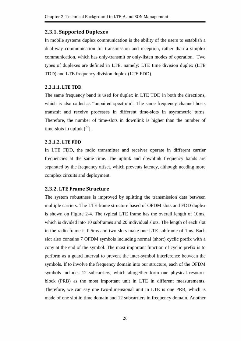
2.3.2. LTE Frame Structure .......................................................................... 20
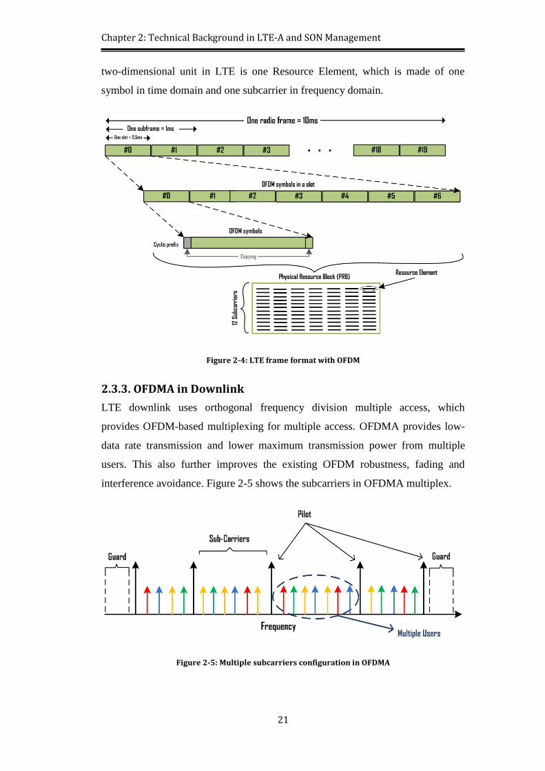
2.3.3. OFDMA in Downlink ......................................................................... 21
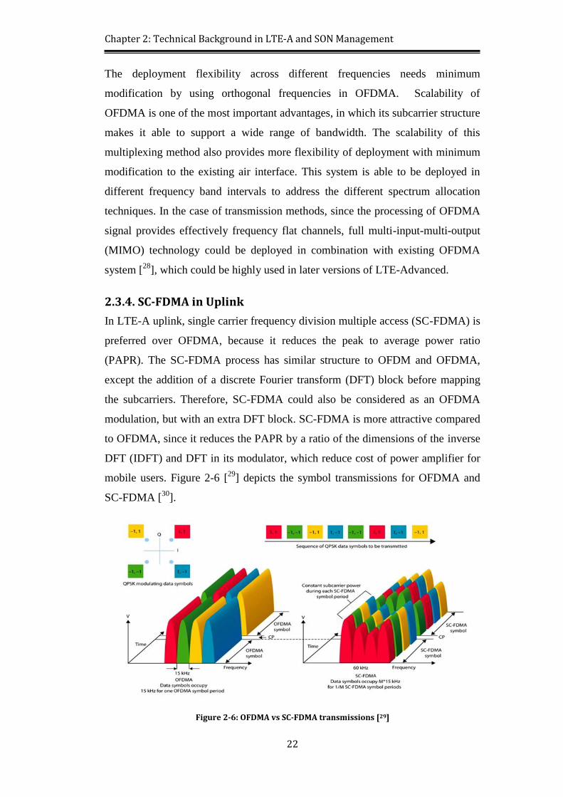
2.3.4. SC-FDMA in Uplink ........................................................................... 22
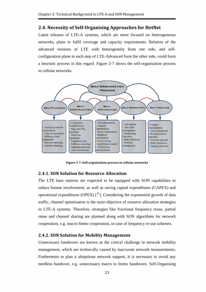
2.4. Necessity of Self-Organising Approaches for HetNet ............................... 23
2.4.1. SON Solution for Resource Allocation ............................................... 23
2.4.2. SON Solution for Mobility Management ............................................ 23
2.4.3. SON Solution for Interference Coordination ...................................... 24
2.5. Deployment Structure and Interfaces ......................................................... 24
2.5.1. Deployment Methodologies ................................................................ 24
2.5.1.1. Multi-Channel Deployment .......................................................... 24
2.5.1.2. Co-Channel Deployment ............................................................... 25
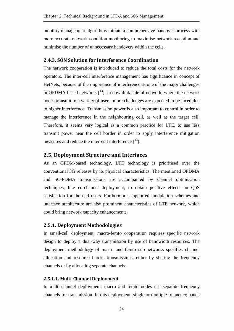
2.5.2. Modulation Schemes ........................................................................... 25
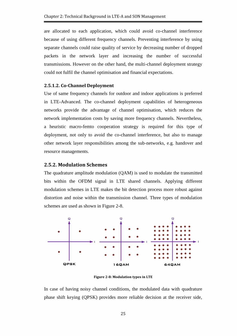
2.5.3. Interface Architecture ......................................................................... 26
2.6. Channel Sharing and Access Control Necessity ........................................ 26
2.6.1. Resource Allocation Scheme .............................................................. 27
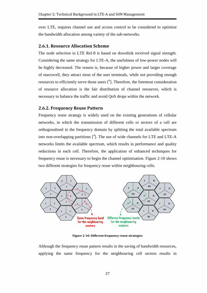
2.6.2. Frequency Reuse Pattern ..................................................................... 27
2.6.3. Network Access Modes ...................................................................... 28
2.6.3.1. Open Subcarrier Group ................................................................. 28
2.6.3.2. Closed Subcarrier Group ............................................................... 28
2.6.3.3. Hybrid Access Mode ..................................................................... 28
Page 9
ix
2.7. LTE-Advanced Technical Challenges ....................................................... 29
2.7.1. Capacity and Coverage Support .......................................................... 29
2.7.2. Overall Quality of Service in HetNets ................................................ 30
2.7.3. Channel Optimisation and Resource Allocation ................................. 30
2.7.4. Mobility Management and Handover ................................................. 30
2.7.5. Interference Challenge and Mitigation Plan ....................................... 30
2.8. Summary .................................................................................................... 31
Chapter 3 Multi-Layer Sub-Channel Allocation and Access Control .................. 32
3.1. Chapter Introduction .................................................................................. 32
3.2. Related Work ............................................................................................. 35
3.3. Problem Statement ..................................................................................... 39
3.4. System Model ............................................................................................ 40
3.4.1. Channel Division ................................................................................. 41
3.4.2. Macrocell and Femtocell Air Interfaces .............................................. 42
3.4.3. Fractional Frequency Reuse ................................................................ 44
3.4.3.1. Strict Fractional Frequency Reuse Scheme .................................. 45
3.4.3.2. Soft Fractional Frequency Reuse Scheme .................................... 46
3.4.3.3. Hybrid Fractional Frequency Reuse (HFFR) Scheme .................. 47
3.4.4. Sub-Channel Allocation Mechanism .................................................. 50
3.5. System Implementation .............................................................................. 52
3.5.1. Network Simulator Software .............................................................. 53
3.5.2. Simulation Scenarios ........................................................................... 54
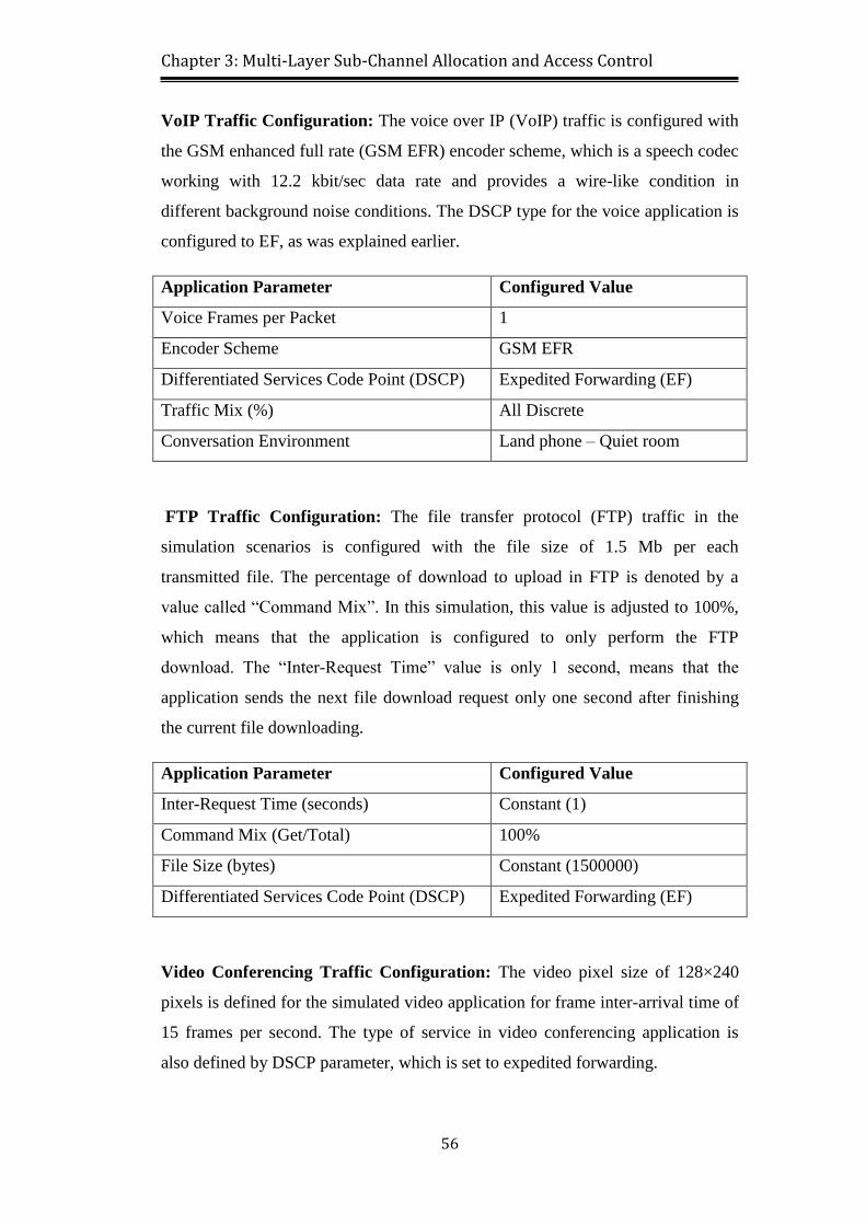
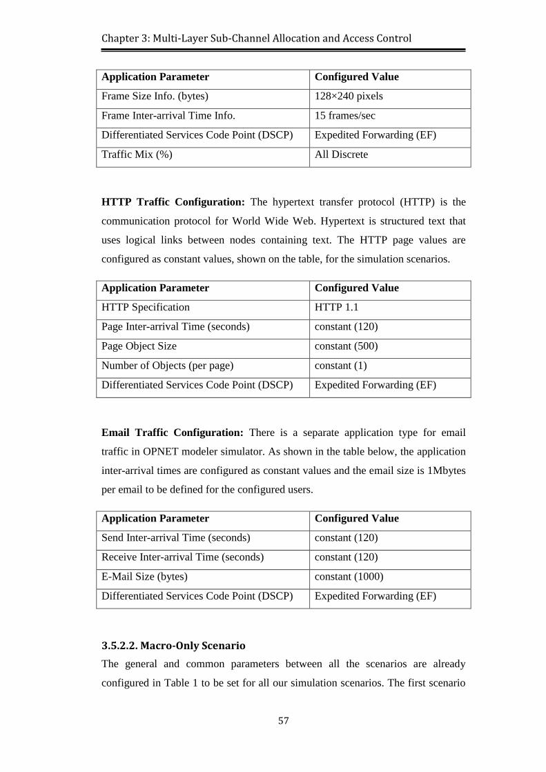
3.5.2.1. Applications’ Specification ........................................................... 55
3.5.2.2. Macro-Only Scenario .................................................................... 57
3.5.2.3. Macro-Femto Scenario without Resource Allocation ................... 59
3.5.2.4. Macro-Femto Scenario with SON Resource Allocation ............... 62
3.6. System Analysis ......................................................................................... 64
Page 10
x
3.6.1. Standard Deviation Method for Simulation Results ........................... 64
3.6.2. Simulation Results .............................................................................. 66
3.7. Summary .................................................................................................... 71
Chapter 4 Comprehensive Handover Strategy ...................................................... 73
4.1. Chapter Introduction .................................................................................. 73
4.2. Related Work ............................................................................................. 76
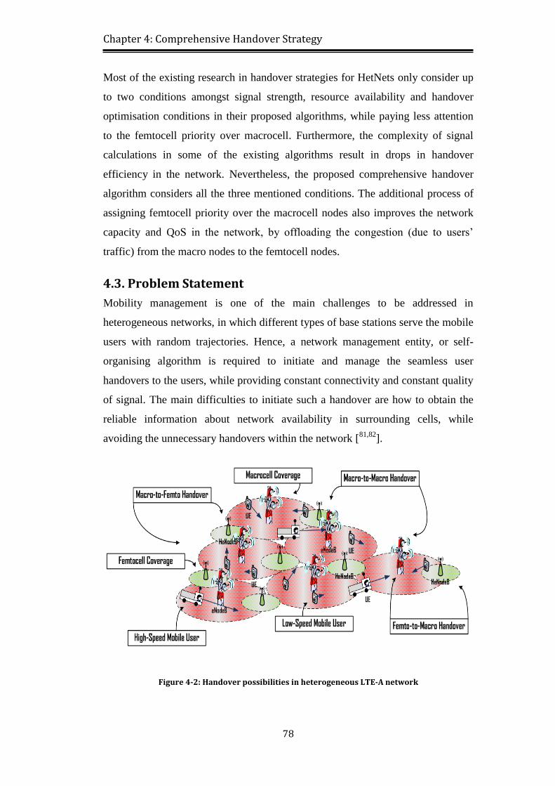
4.3. Problem Statement ..................................................................................... 78
4.4. System Model ............................................................................................ 79
4.4.1. Technical Considerations .................................................................... 80
4.4.2. SON Measurements and Signalling .................................................... 80
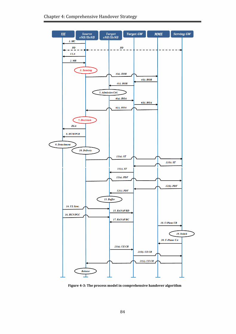
4.4.3. Process Model ..................................................................................... 81
4.4.4. Handover Sensing Process .................................................................. 86
4.4.5. Handover Decision Process ................................................................ 87
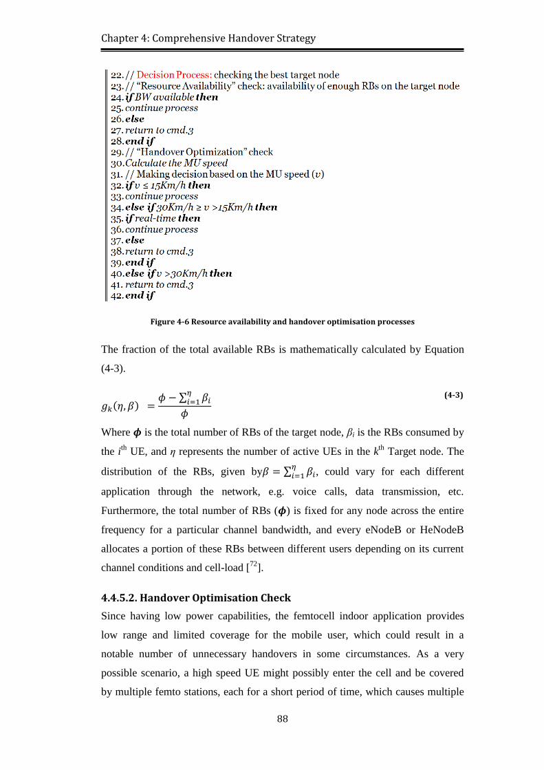
4.4.5.1. Resource Availability Check ........................................................ 87
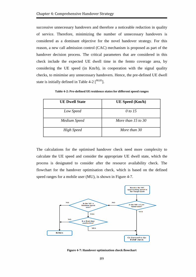
4.4.5.2. Handover Optimisation Check ...................................................... 88
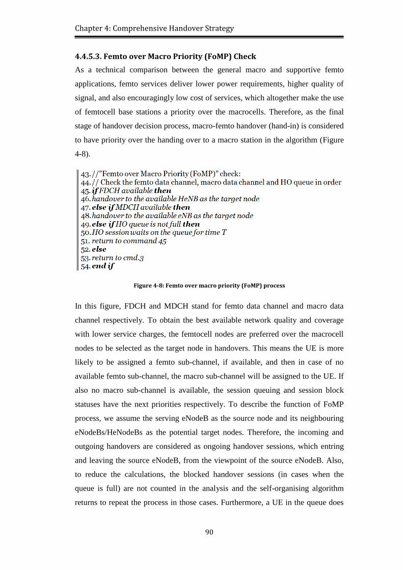
4.4.5.3. Femto over Macro Priority (FoMP) Check ................................... 90
4.5. System Implementation .............................................................................. 94
4.5.1. Packet Transmission from IP Payload ................................................ 95
4.5.2. Simulation Parameters ........................................................................ 95
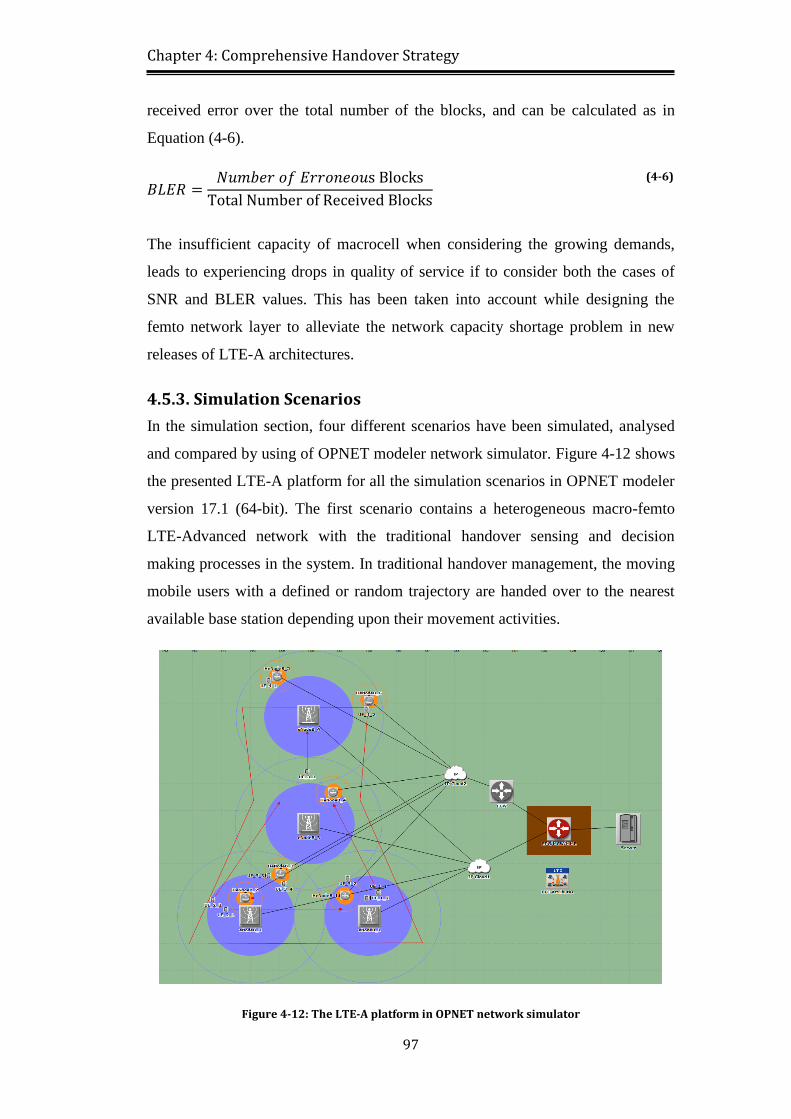
4.5.3. Simulation Scenarios ........................................................................... 97
4.5.4. Handover Algorithm Insertion into the System .................................. 99
4.5.4.1. Sensing Process with RSRP and RSRQ ...................................... 100
4.5.4.2. Resource Availability Check with Resource Blocks (RBs) ........ 100
4.5.4.3. Handover Opt. Check with Call Admission Control (CAC) ...... 100
4.5.4.4. Femto over Macro Priority (FoMP) Check with Data Channels 101
4.6. Simulation Results and Analysis .............................................................. 101
4.7. Summary .................................................................................................. 106
Page 11
xi
Chapter 5 Inter-Cell Interference Coordination .................................................. 108
5.1. Chapter Introduction ................................................................................ 108
5.2. Related Work ........................................................................................... 111
5.3. Problem Statement ................................................................................... 114
5.4. Inter-Cell Interference Coordination Categories ...................................... 115
5.4.1. Inter-Cell Interference Coordination in LTE Releases 8 and 9 ........ 115
5.4.2. Enhanced Inter-Cell Interference Coordination ................................ 116
5.4.2.1. Time-Domain Techniques ........................................................... 116
5.4.2.2. Frequency-Domain Techniques .................................................. 117
5.4.2.3. Power Control Techniques .......................................................... 118
5.5. System Model .......................................................................................... 118
5.5.1. PHASE 1: SINR Measurements ....................................................... 119
5.5.2. PHASE 2: SINR to CQI Mapping .................................................... 124
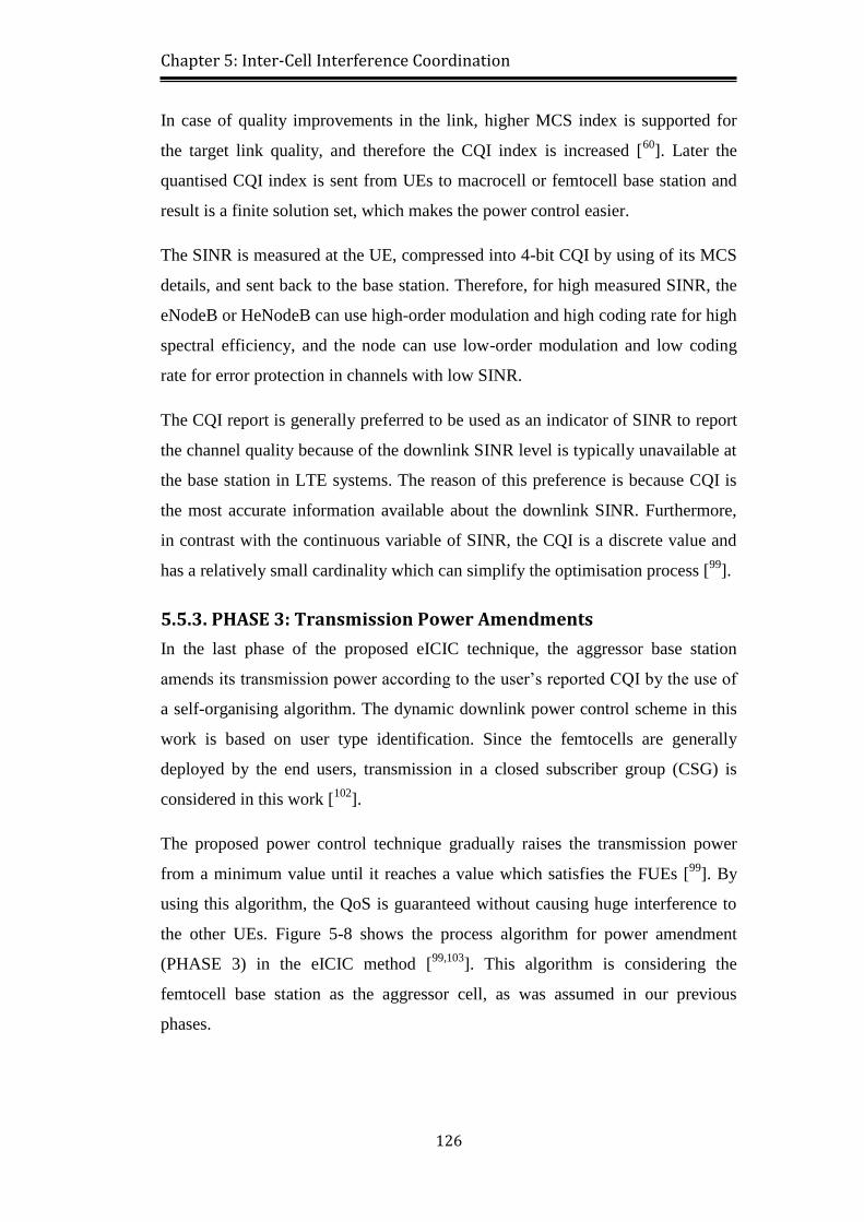
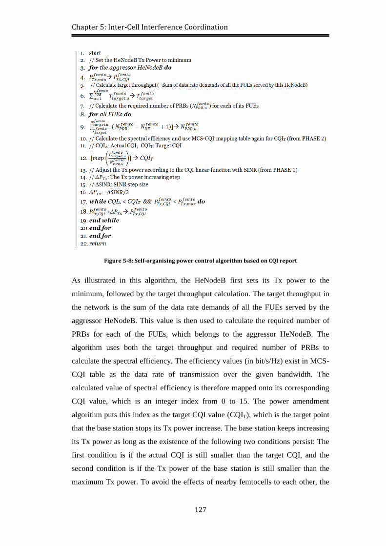
5.5.3. PHASE 3: Transmission Power Amendments .................................. 126
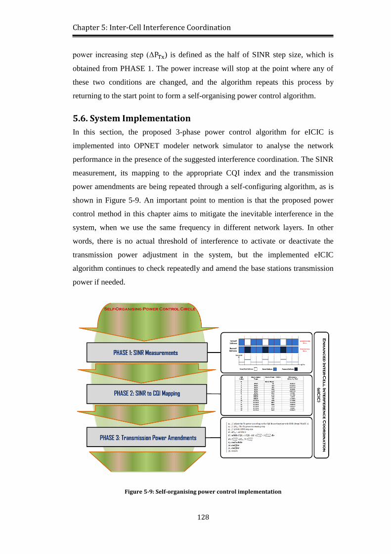
5.6. System Implementation ............................................................................ 128
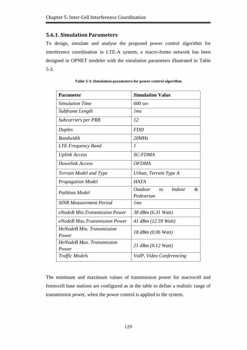
5.6.1. Simulation Parameters ...................................................................... 129
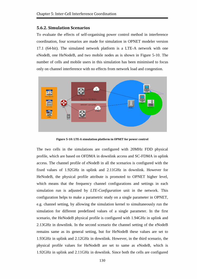
5.6.2. Simulation Scenarios ......................................................................... 130
5.6.3. Power Control Implementation in OPNET ....................................... 131
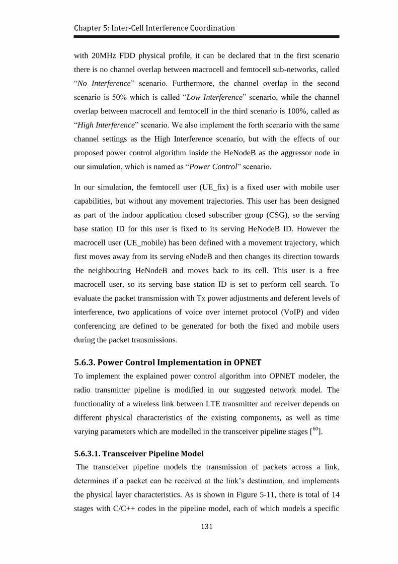
5.6.3.1. Transceiver Pipeline Model ........................................................ 131
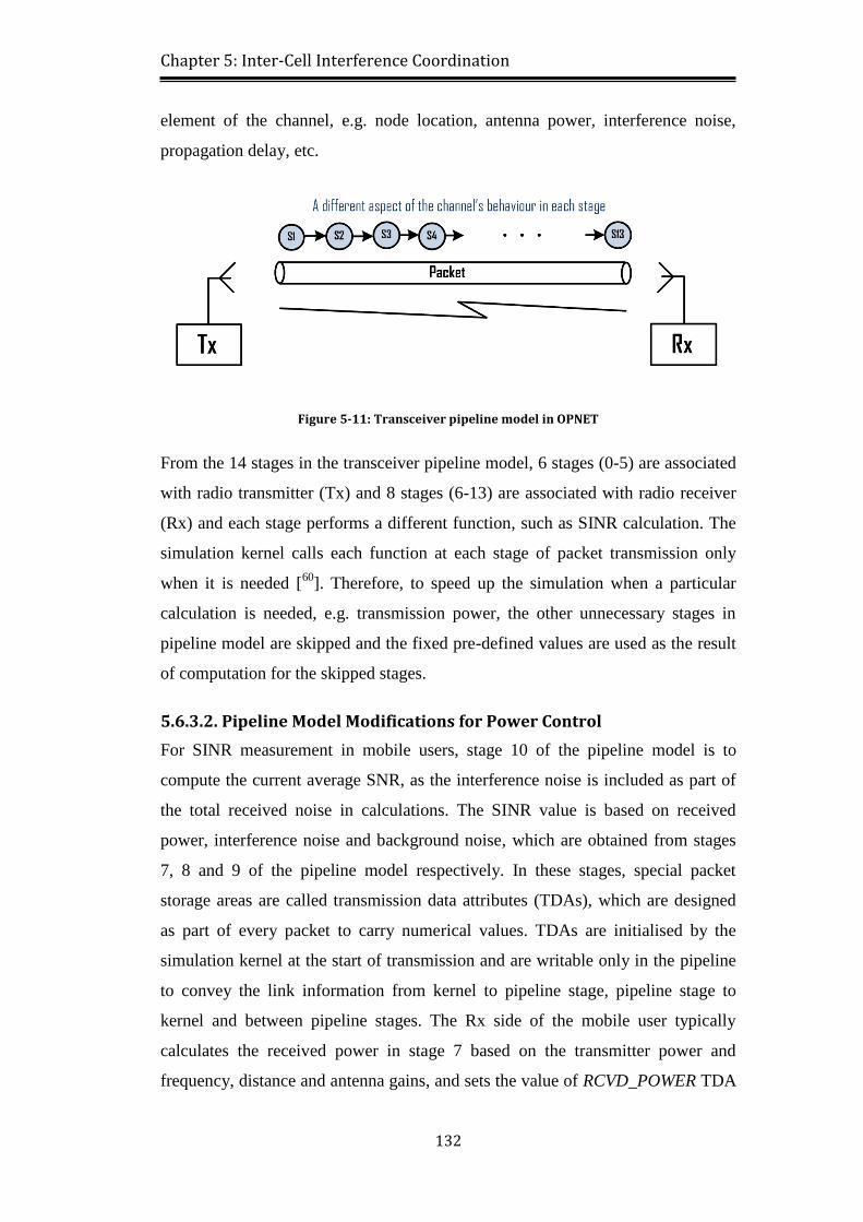
5.6.3.2. Pipeline Model Modifications for Power Control ....................... 132
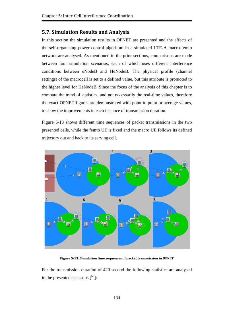
5.7. Simulation Results and Analysis .............................................................. 134
5.8. Summary .................................................................................................. 139
Chapter 6 Conclusions, Discussion and Future Work ........................................ 141
6.1. Conclusions .............................................................................................. 141
6.2. Summary of Thesis Contributions ........................................................... 143
6.3. Discussion ................................................................................................ 144
6.4. Future Work ............................................................................................. 145
Page 12
xii
6.4.1. Further Investigations on Spectrum Sharing ..................................... 145
6.4.2. Further Investigations on Handover Initiation .................................. 145
6.4.3. Further Investigations on Interference Sensing ................................ 145
References ........................................................................................................... 146
Appendix A ......................................................................................................... 158
Page 13
xiii
List of Figures
Figure 1-1: Cellular network evolutions ................................................................. 1
Figure 1-2: Existing LTE supportive techniques over the mobile networks .......... 3
Figure 1-3: HetNet architecture in LTE-A networks .............................................. 4
Figure 1-4: SON functionalities over HetNet deployment ..................................... 6
Figure 1-5: Thesis main contributions on LTE-A system ....................................... 9
Figure 1-6: Multi-layer system architecture for LTE-A network ......................... 11
Figure 2-1: Network evaluation techniques towards LTE and LTE-A ................. 14
Figure 2-2: Variety of nodes in heterogeneous network architecture ................... 17
Figure 2-3: Range-extension for macro-pico network .......................................... 18
Figure 2-4: LTE frame format with OFDM .......................................................... 21
Figure 2-5: Multiple subcarriers configuration in OFDMA ................................. 21
Figure 2-6: OFDMA vs SC-FDMA transmissions [29] ......................................... 22
Figure 2-7: Self-organisation process in cellular networks .................................. 23
Figure 2-8: Modulation types in LTE ................................................................... 25
Figure 2-9: Entire LTE interfaces architecture ..................................................... 26
Figure 2-10: Different frequency reuse strategies ................................................. 27
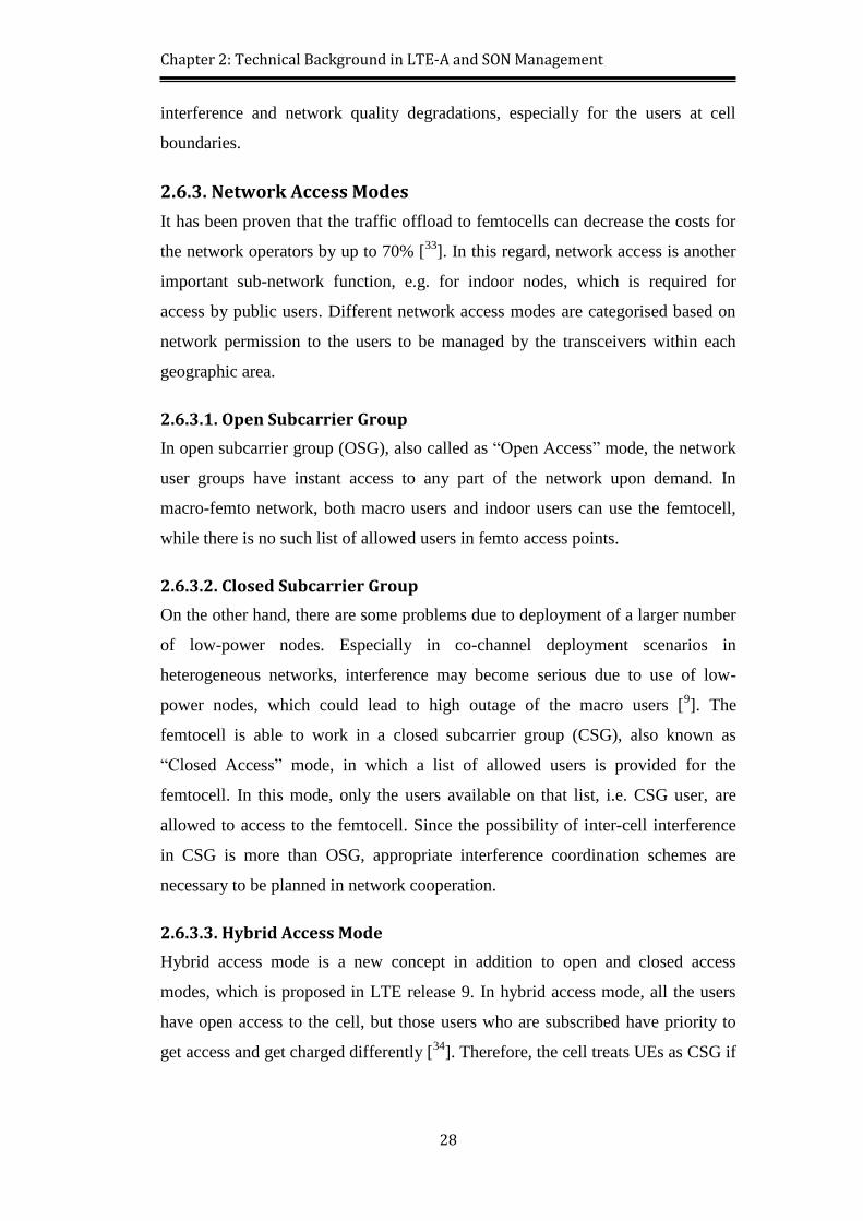
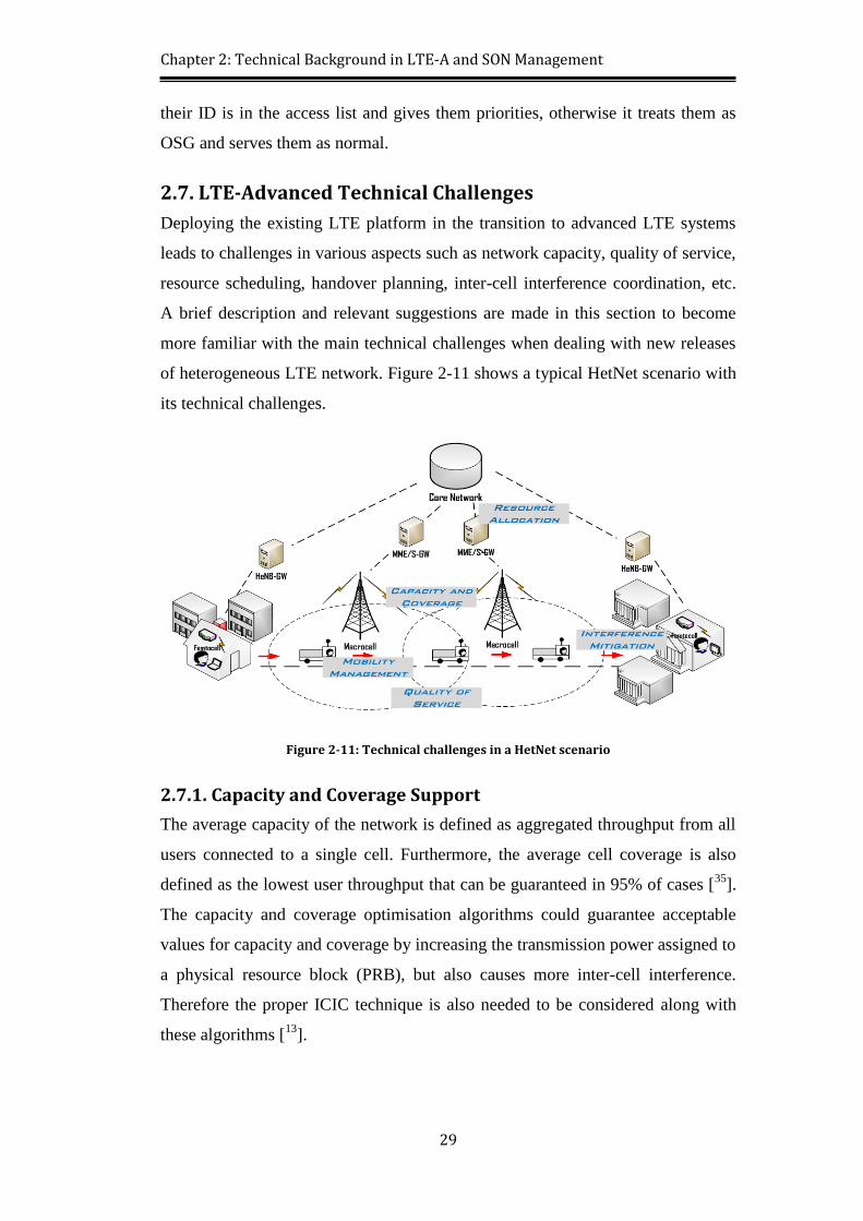
Figure 2-11: Technical challenges in a HetNet scenario ...................................... 29
Figure 3-1: Carrier aggregation process in LTE-A systems ................................. 34
Figure 3-2: Hardware requirements for resource management in LTE-A ............ 34
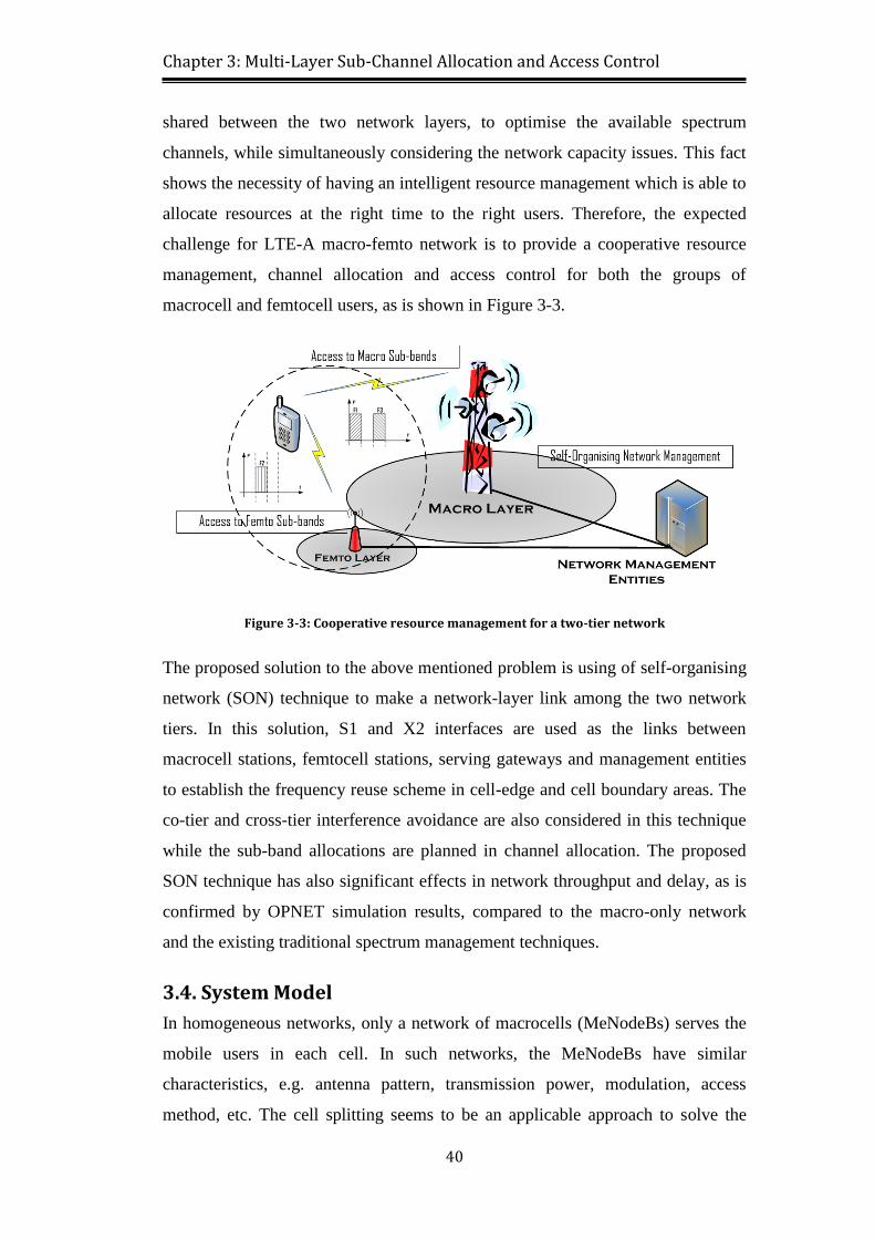
Figure 3-3: Cooperative resource management for a two-tier network ................ 40
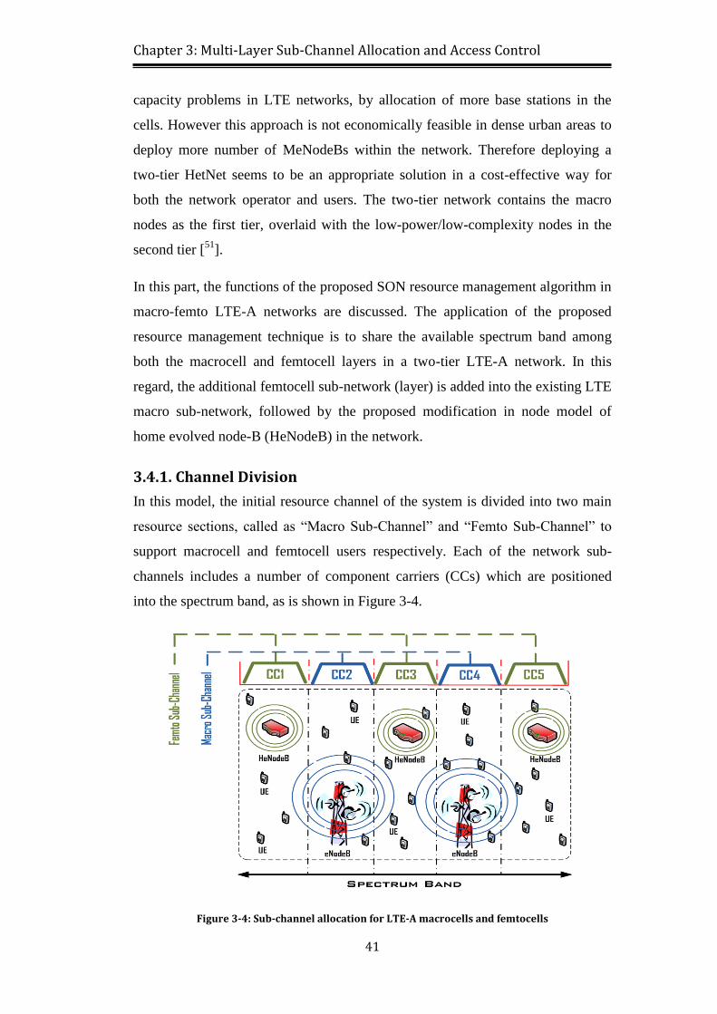
Figure 3-4: Sub-channel allocation for LTE-A macrocells and femtocells .......... 41
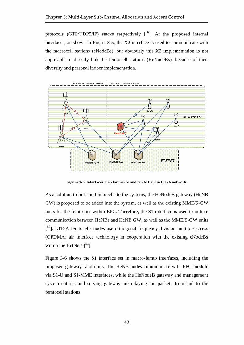
Figure 3-5: Interfaces map for macro and femto tiers in LTE-A network ............ 43
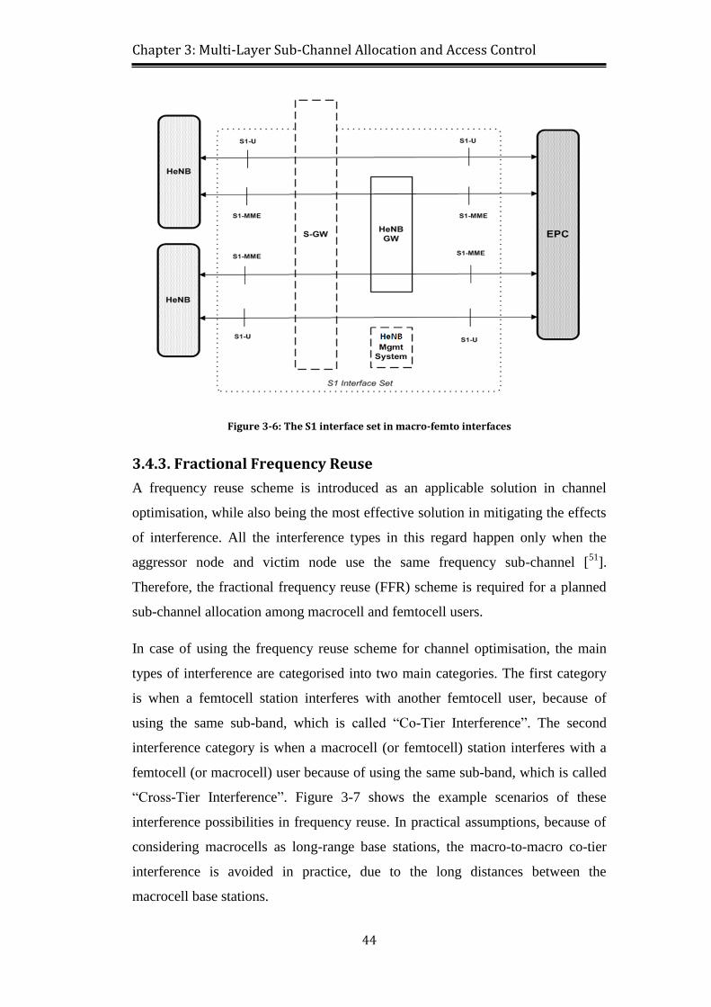
Figure 3-6: The S1 interface set in macro-femto interfaces .................................. 44
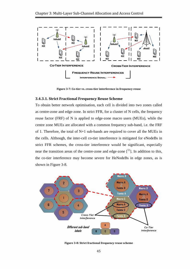
Figure 3-7: Co-tier vs. cross-tier interference in frequency reuse ........................ 45
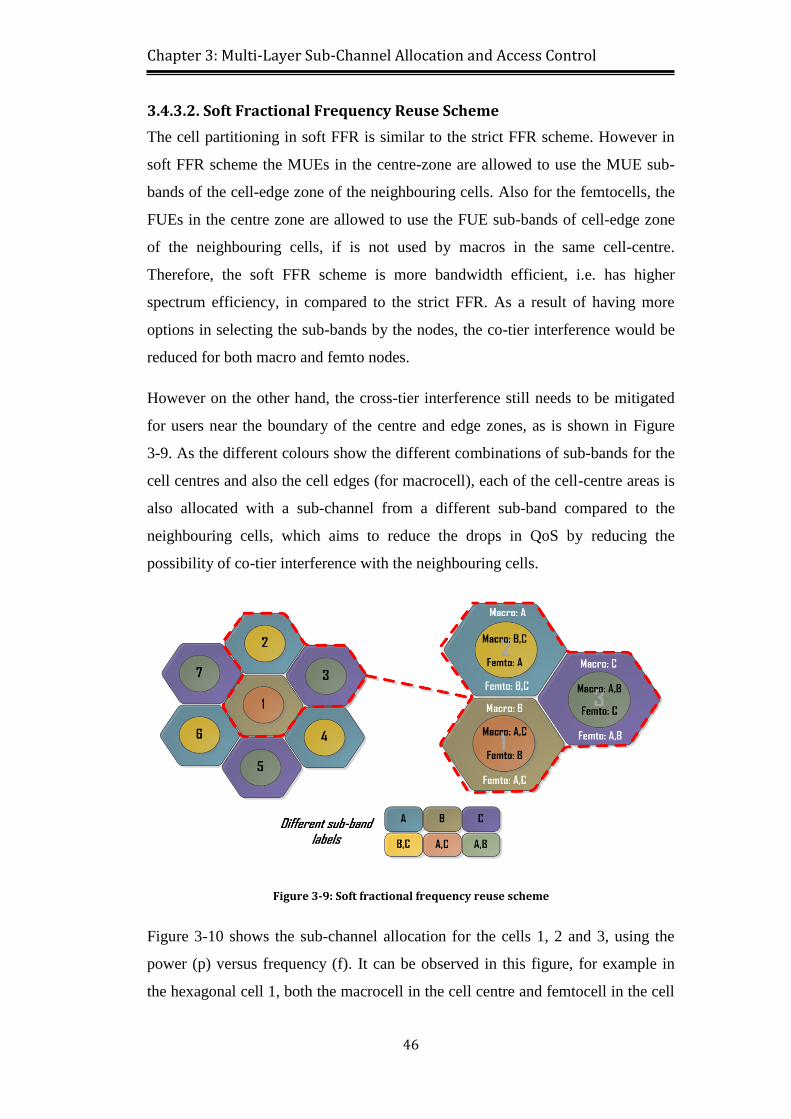
Figure 3-8: Strict fractional frequency reuse scheme ........................................... 45
Figure 3-9: Soft fractional frequency reuse scheme ............................................. 46
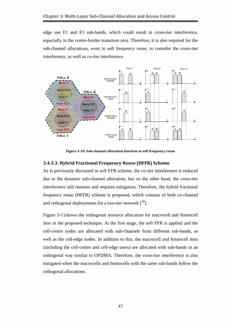
Figure 3-10: Sub-channel allocation function in soft frequency reuse ................. 47
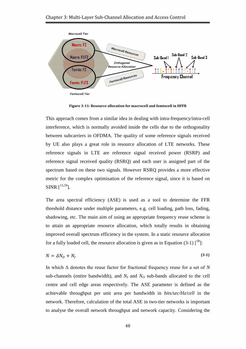
Figure 3-11: Resource allocation for macrocell and femtocell in HFFR .............. 48
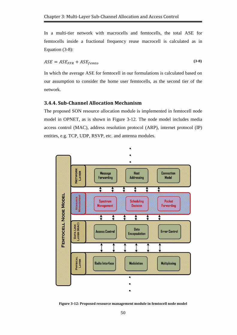
Figure 3-12: Proposed resource management module in femtocell node model .. 50
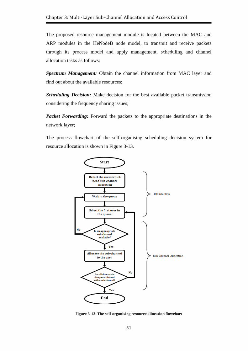
Figure 3-13: The self-organising resource allocation flowchart ........................... 51
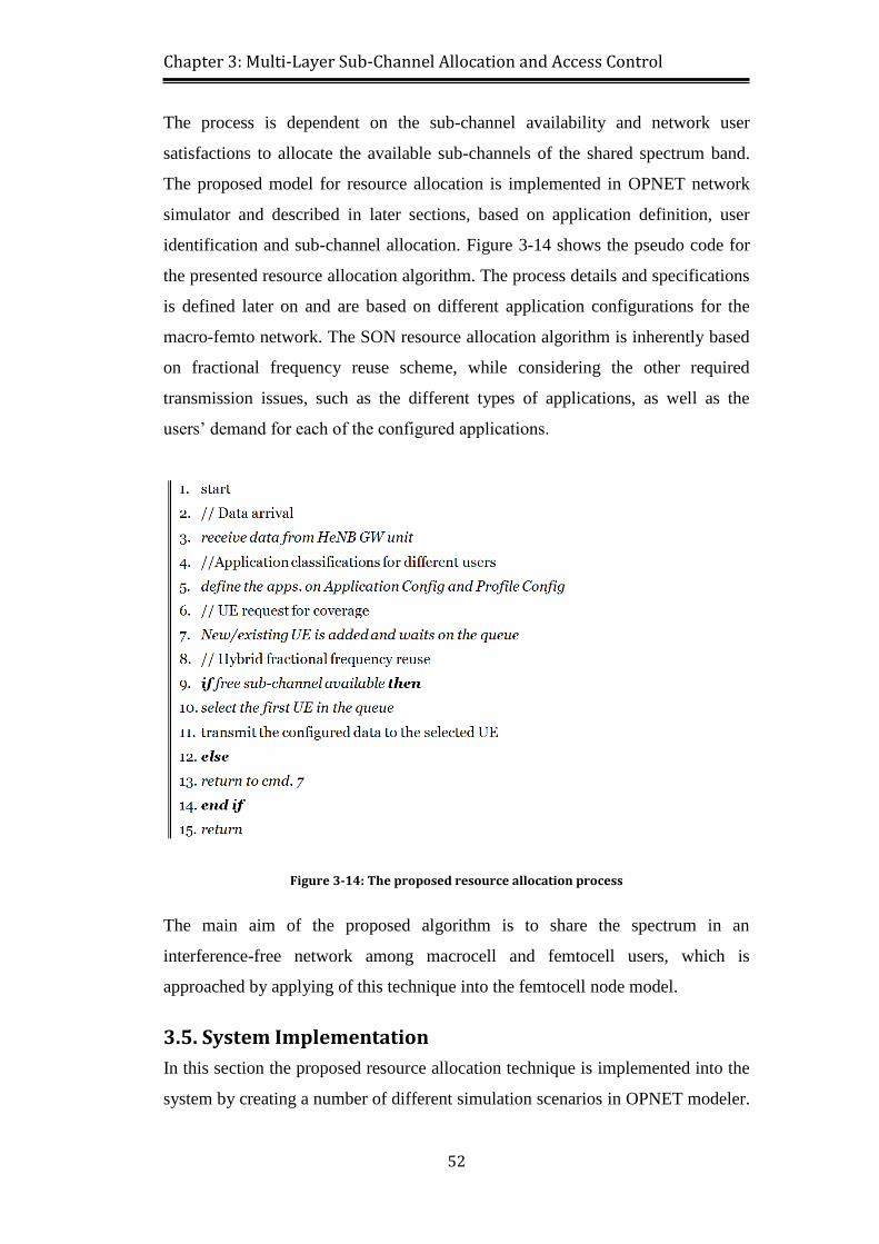
Figure 3-14: The proposed resource allocation process ........................................ 52
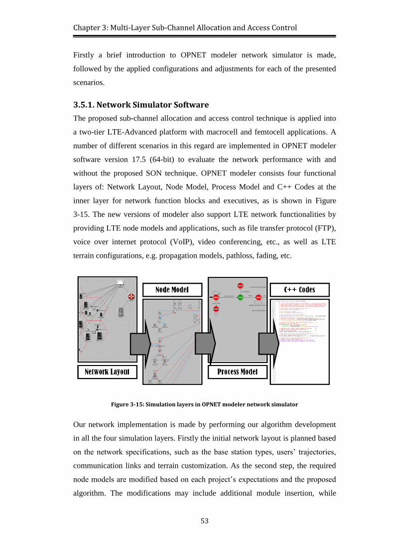
Figure 3-15: Simulation layers in OPNET modeler network simulator ............... 53
Page 14
xiv
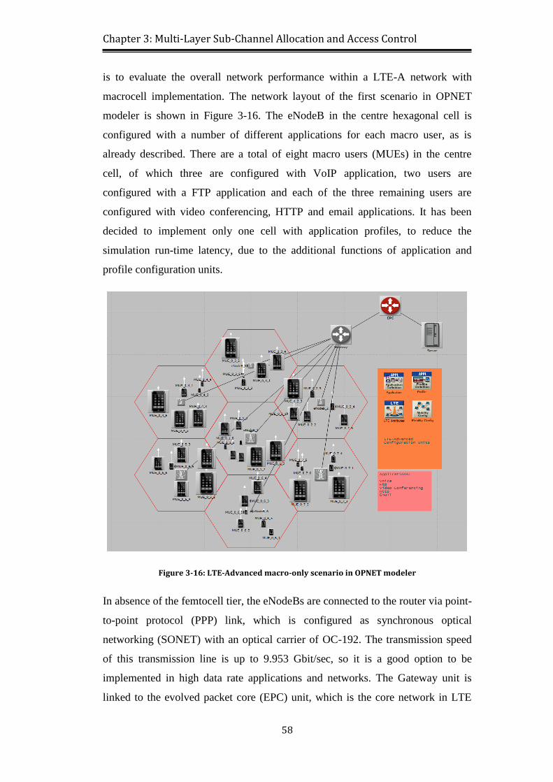
Figure 3-16: LTE-Advanced macro-only scenario in OPNET modeler ............... 58
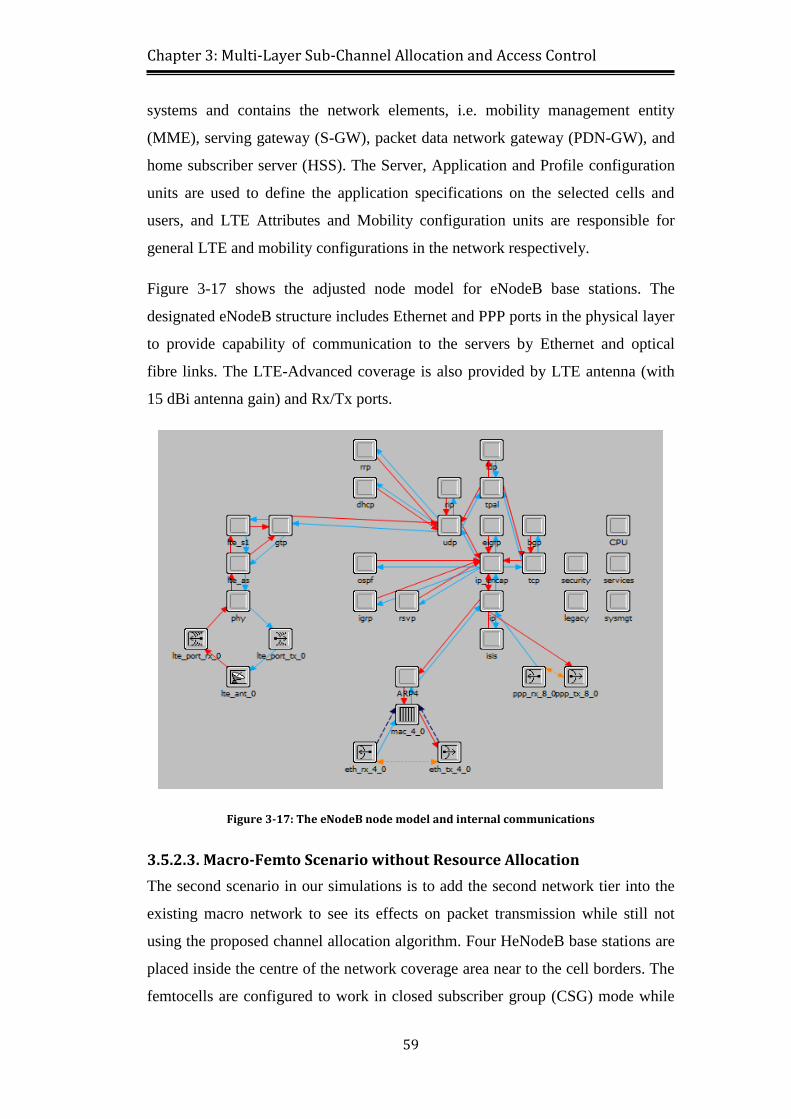
Figure 3-17: The eNodeB node model and internal communications .................. 59
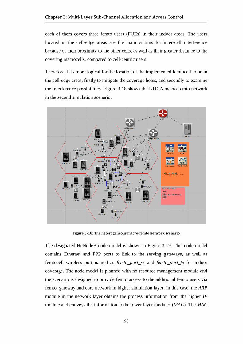
Figure 3-18: The heterogeneous macro-femto network scenario ......................... 60
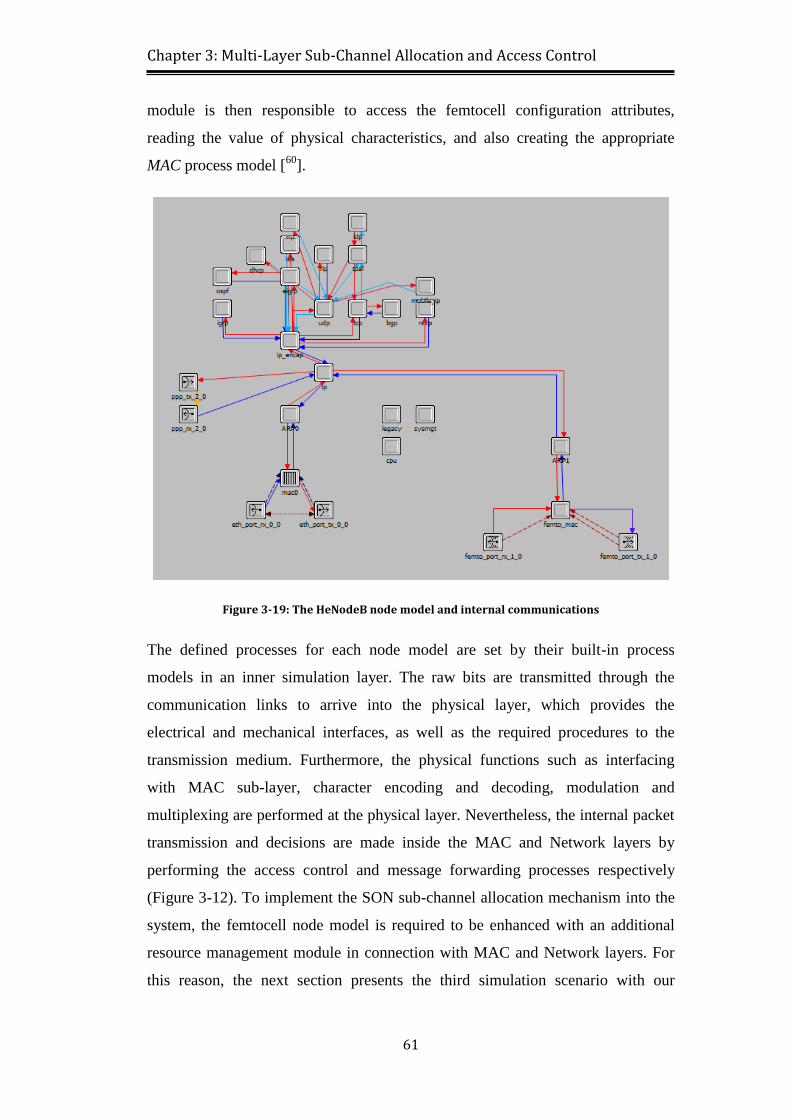
Figure 3-19: The HeNodeB node model and internal communications ............... 61
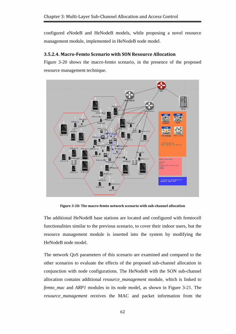
Figure 3-20: The macro-femto network scenario with sub-channel allocation .... 62
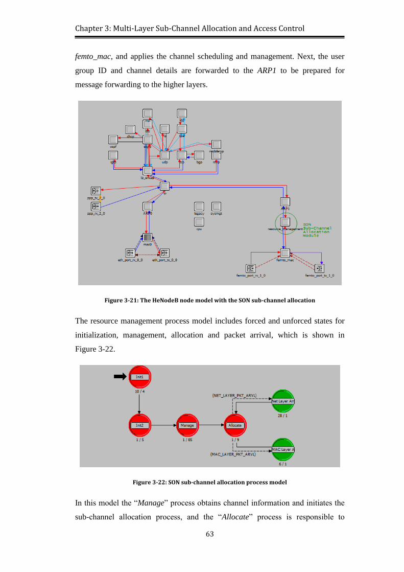
Figure 3-21: The HeNodeB node model with the SON sub-channel allocation ... 63
Figure 3-22: SON sub-channel allocation process model ..................................... 63
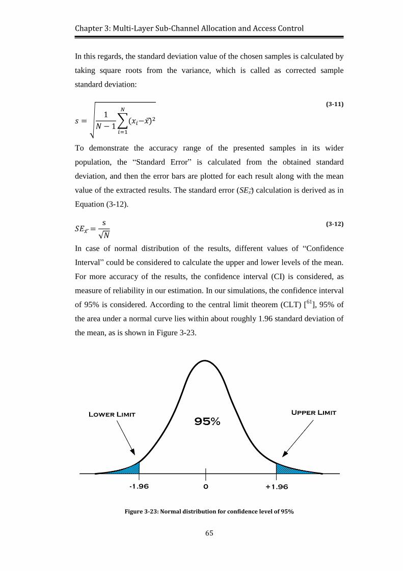
Figure 3-23: Normal distribution for confidence level of 95% ............................ 65
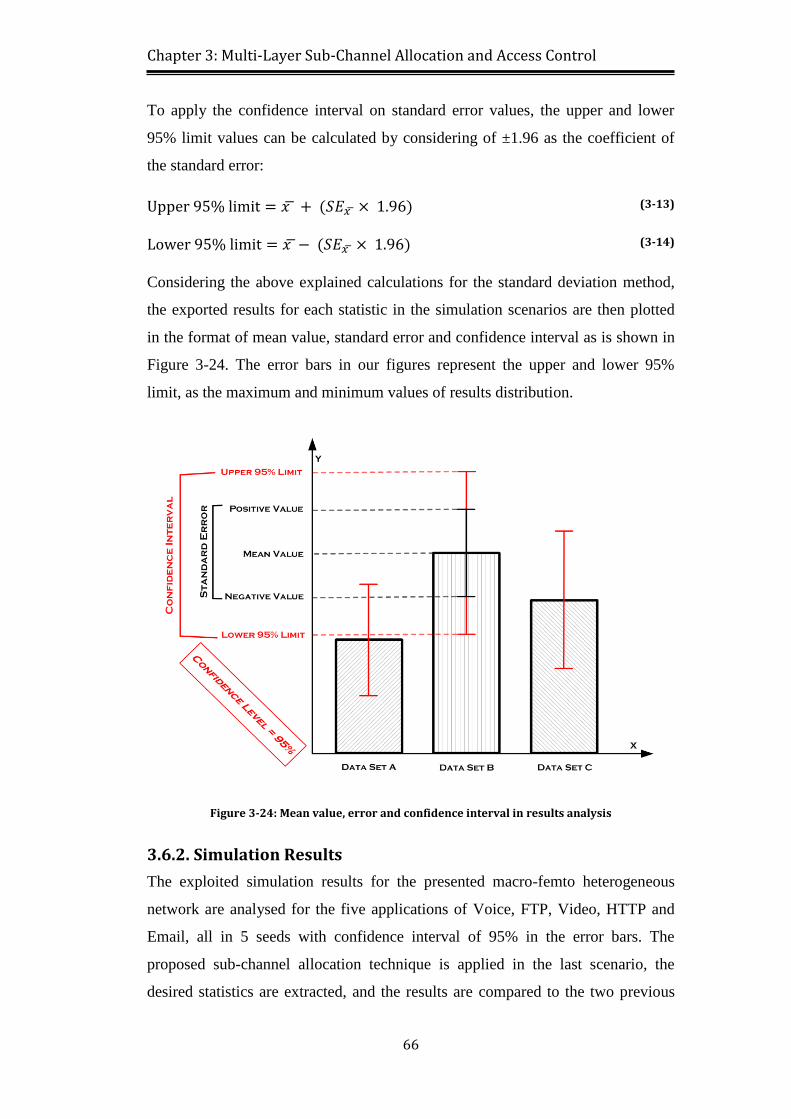
Figure 3-24: Mean value, error and confidence interval in results analysis ......... 66
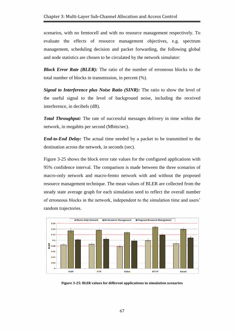
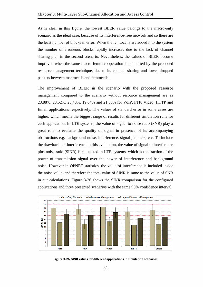
Figure 3-25: BLER values for different applications in simulation scenarios ...... 67
Figure 3-26: SINR values for different applications in simulation scenarios ....... 68
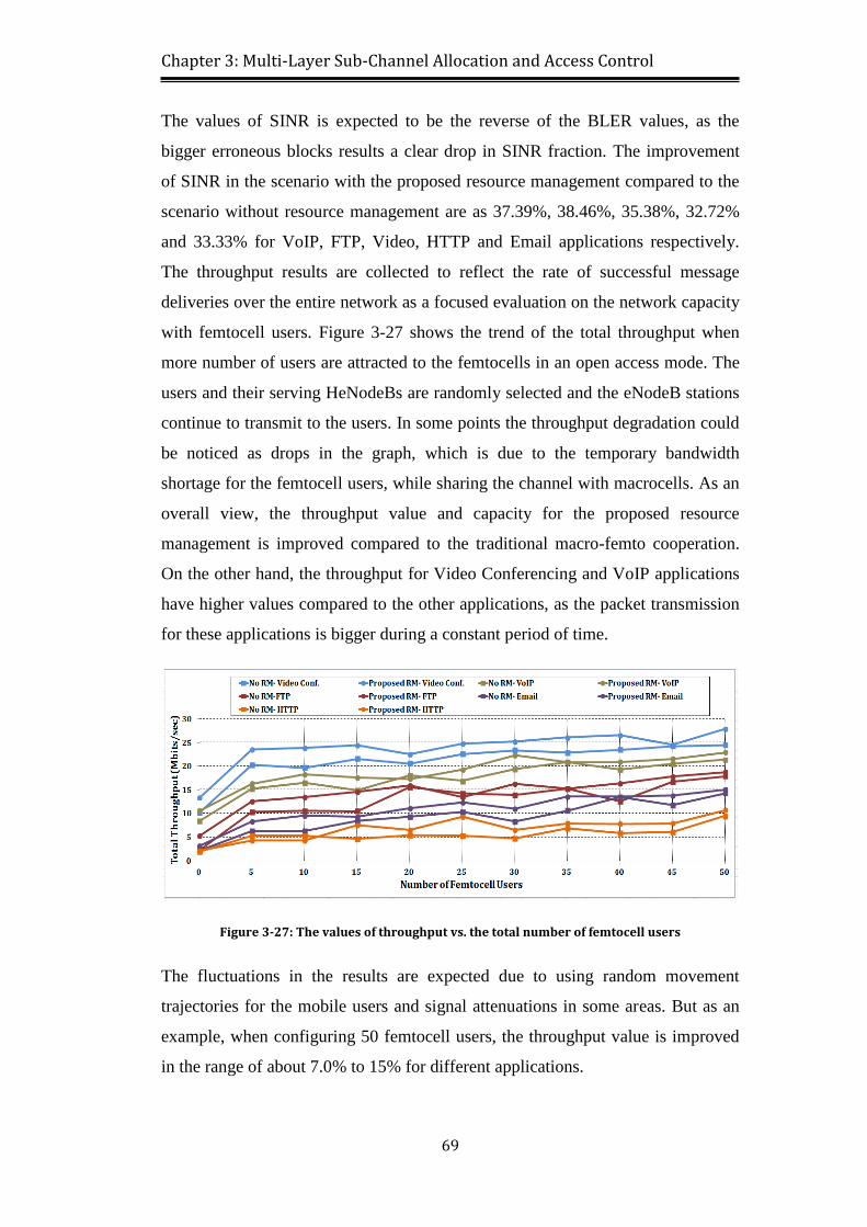
Figure 3-27: The values of throughput vs. the total number of femtocell users ... 69
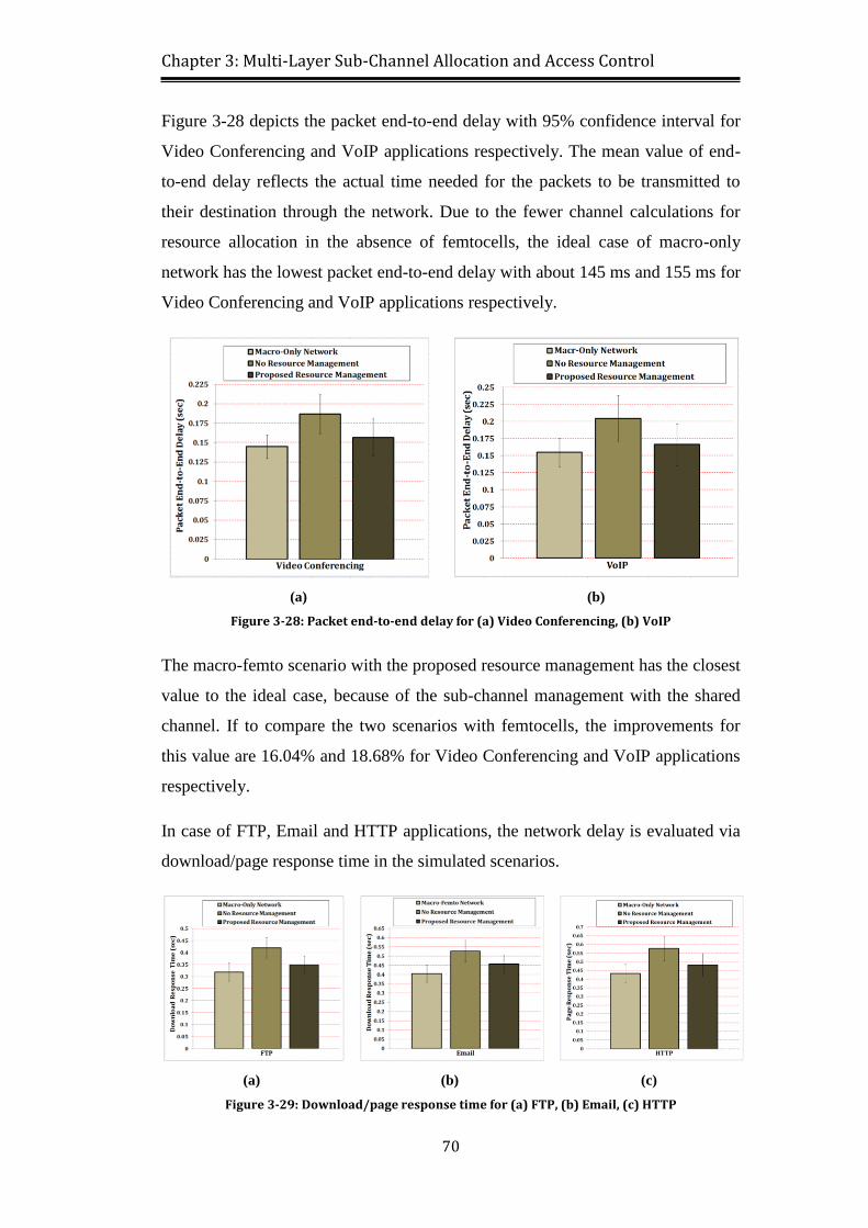
Figure 3-28: Packet end-to-end delay for (a) Video Conferencing, (b) VoIP ...... 70
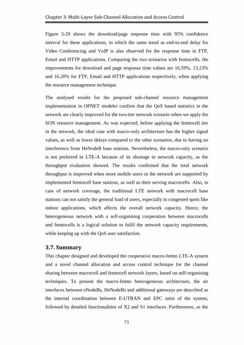
Figure 3-29: Download/page response time for (a) FTP, (b) Email, (c) HTTP .... 70
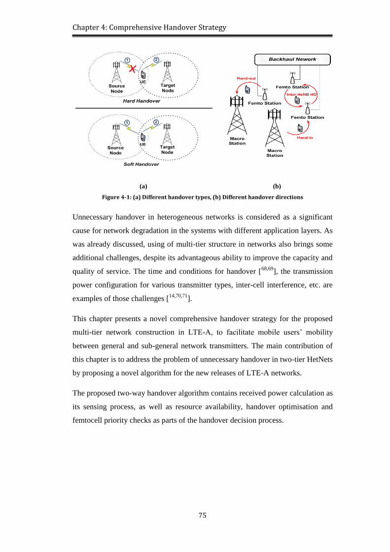
Figure 4-1: (a) Different handover types, (b) Different handover directions ....... 75
Figure 4-2: Handover possibilities in heterogeneous LTE-A network ................. 78
Figure 4-3: The process model in comprehensive handover algorithm ................ 84
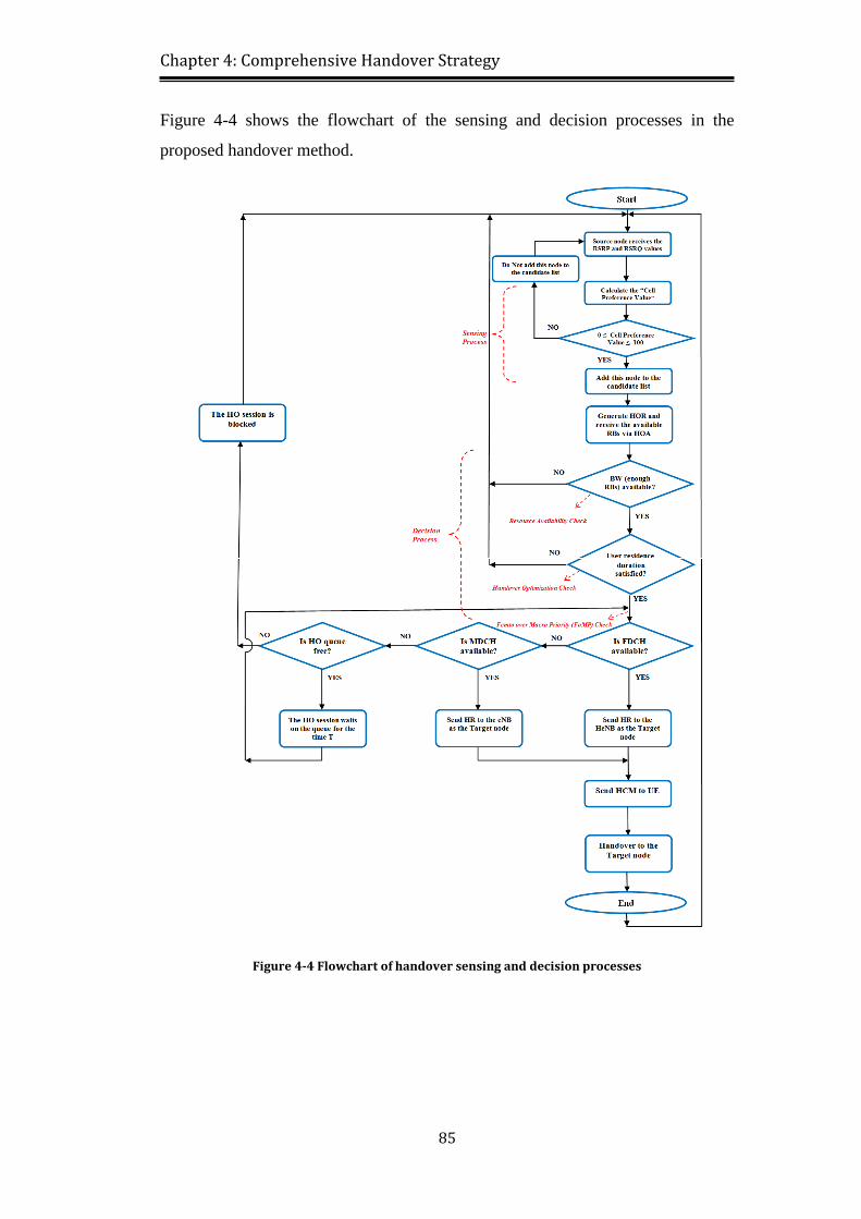
Figure 4-4 Flowchart of handover sensing and decision processes ...................... 85
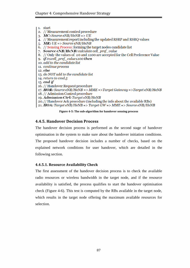
Figure 4-5: The sub-algorithm for handover sensing process ............................... 87
Figure 4-6 Resource availability and handover optimisation processes ............... 88
Figure 4-7: Handover optimisation check flowchart ............................................ 89
Figure 4-8: Femto over macro priority (FoMP) process ....................................... 90
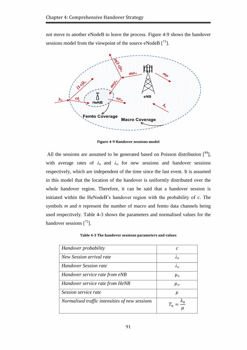
Figure 4-9 Handover sessions model .................................................................... 91
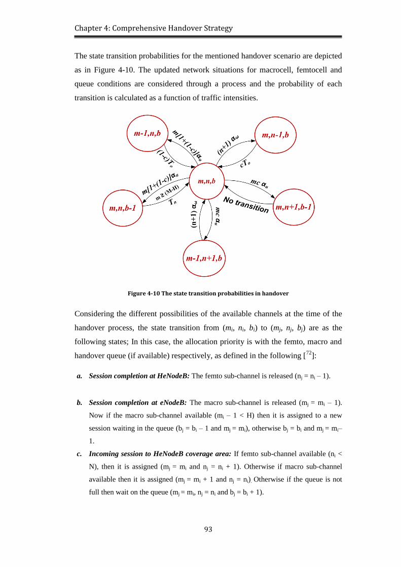
Figure 4-10 The state transition probabilities in handover ................................... 93
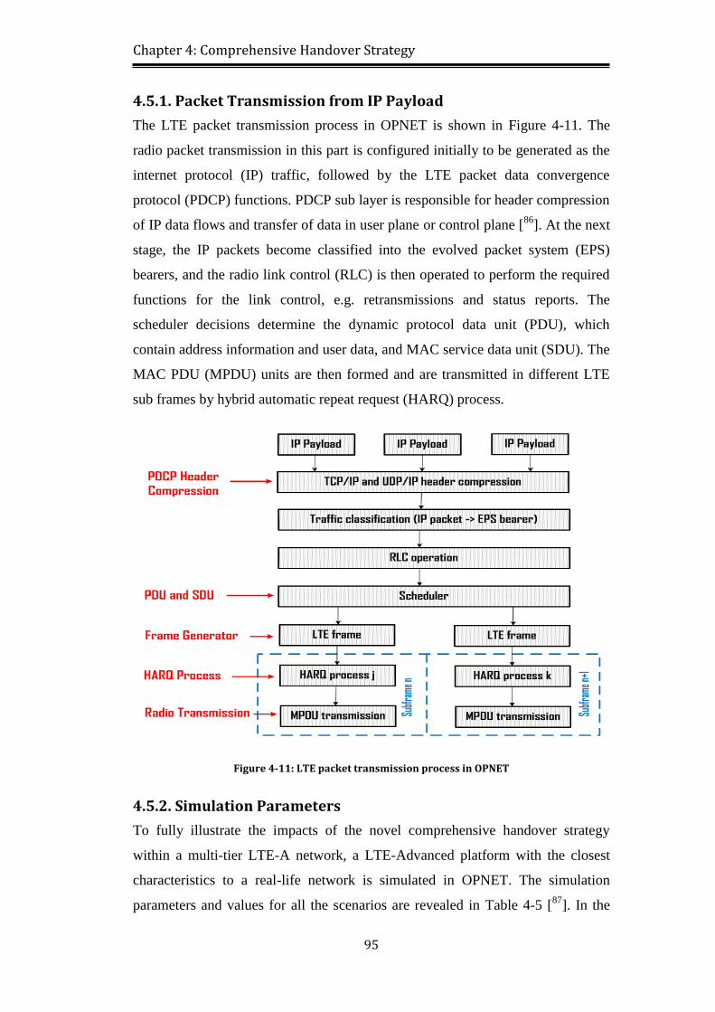
Figure 4-11: LTE packet transmission process in OPNET ................................... 95
Figure 4-12: The LTE-A platform in OPNET network simulator ........................ 97
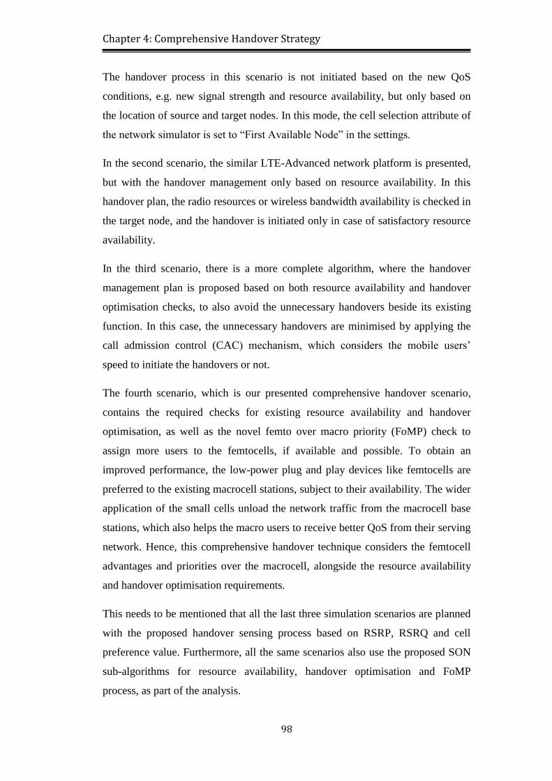
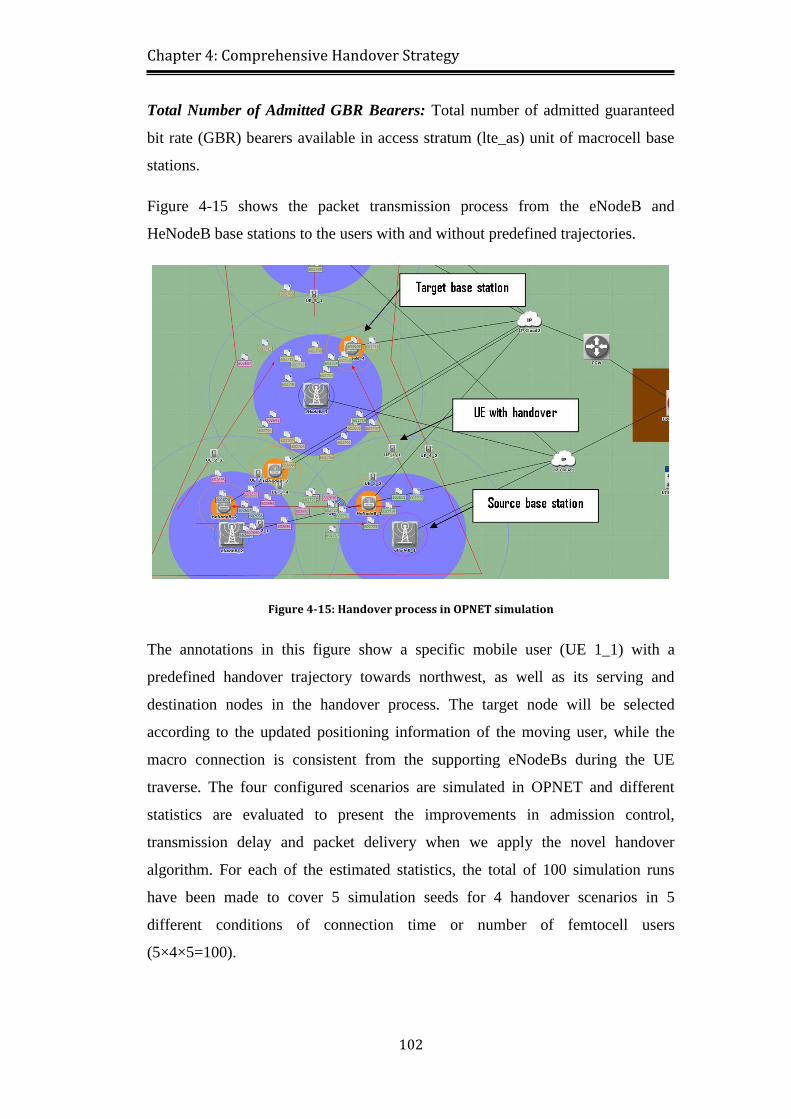
Figure 4-13: The simulation scenarios and their relevant considerations ............. 99
Figure 4-14: UE and eNodeB node models ........................................................ 100
Figure 4-15: Handover process in OPNET simulation ....................................... 102
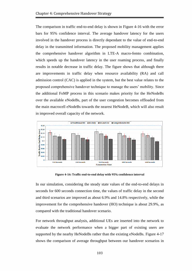
Figure 4-16: Traffic end-to-end delay with 95% confidence interval ................ 103
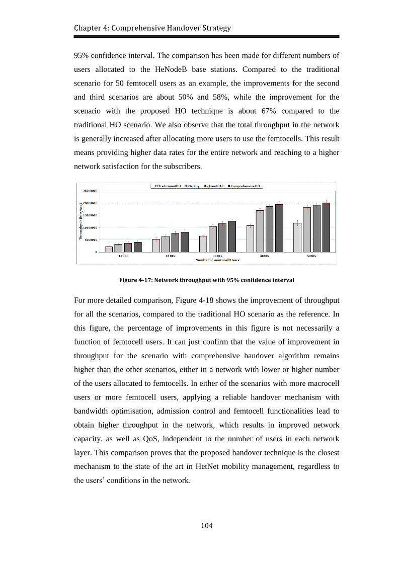
Figure 4-17: Network throughput with 95% confidence interval ....................... 104
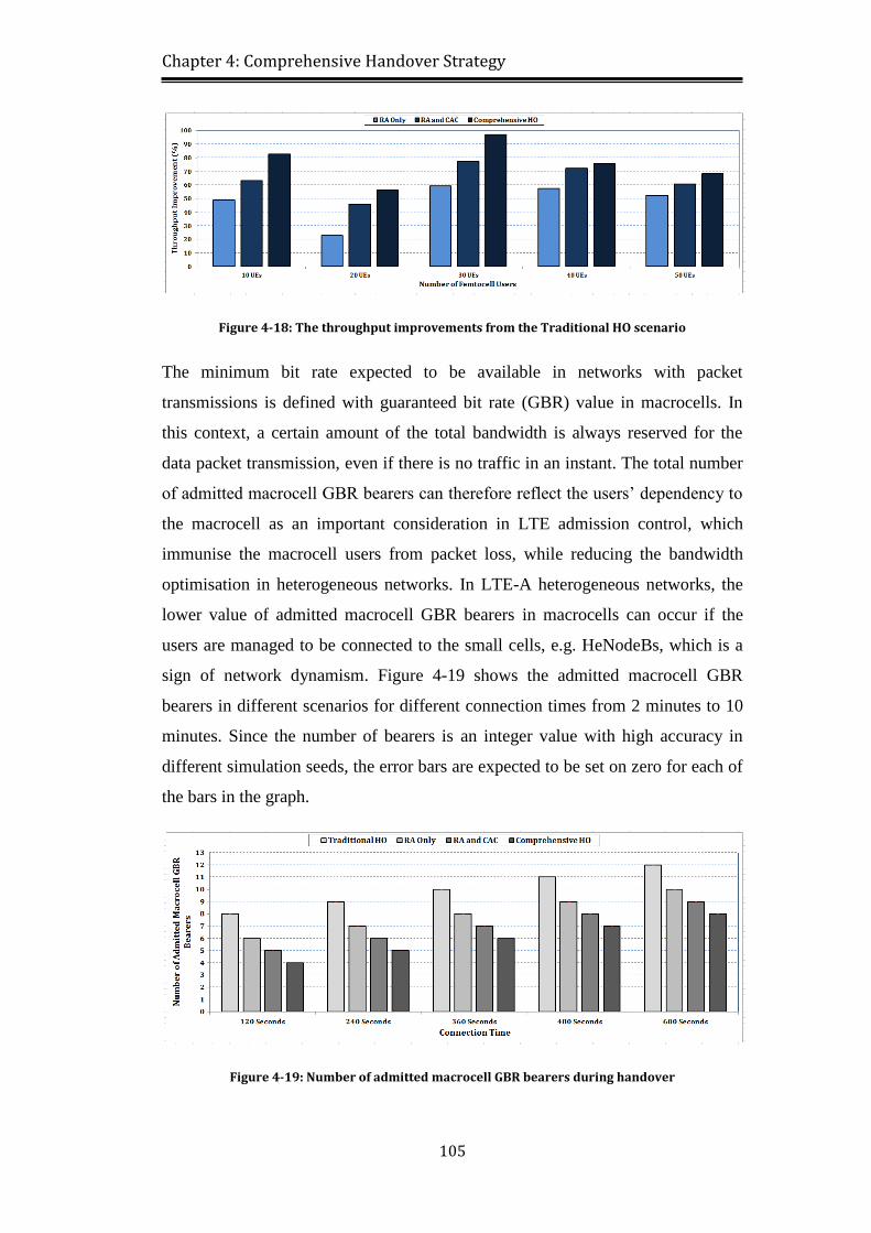
Figure 4-18: The throughput improvements from the Traditional HO scenario . 105
Figure 4-19: Number of admitted macrocell GBR bearers during handover ..... 105
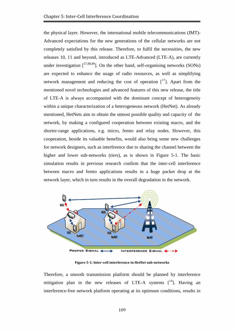
Figure 5-1: Inter-cell interference in HetNet sub-networks ................................ 109
Page 15
xv
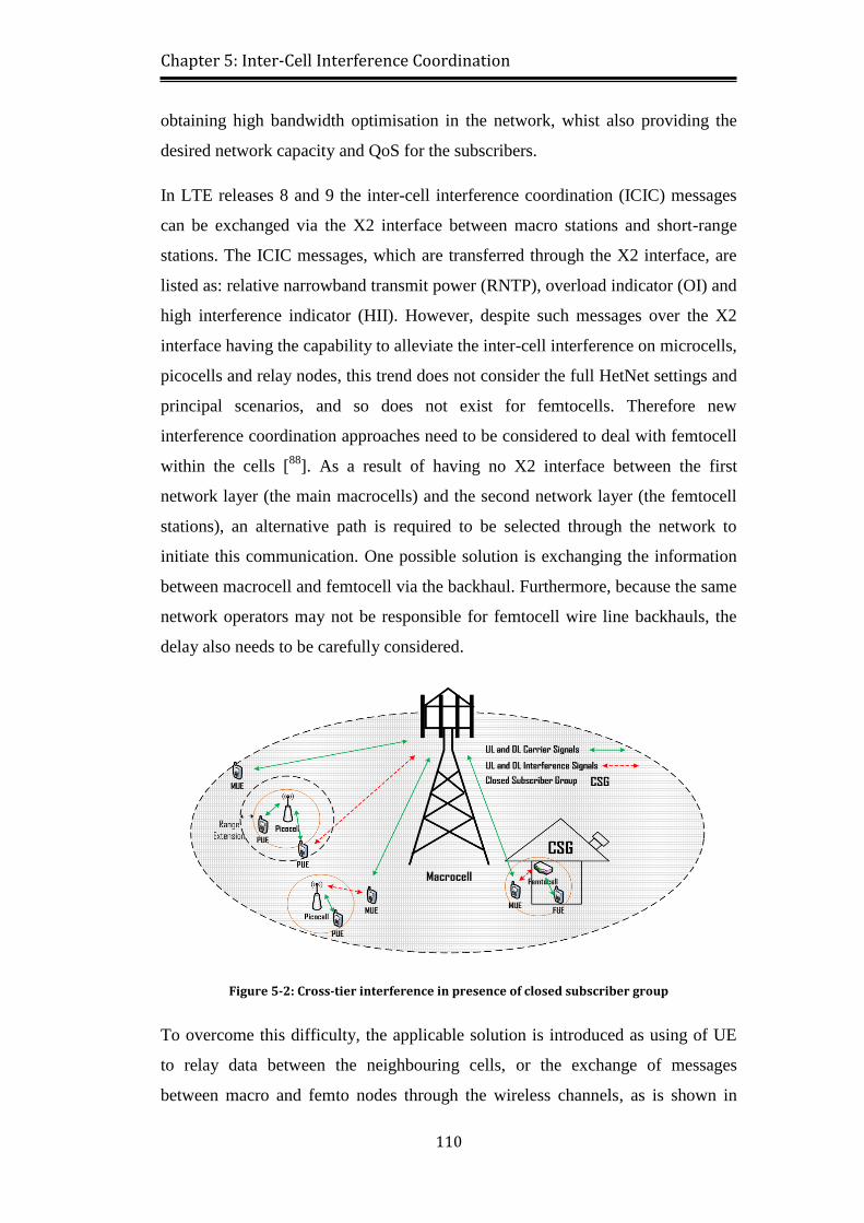
Figure 5-2: Cross-tier interference in presence of closed subscriber group ....... 110
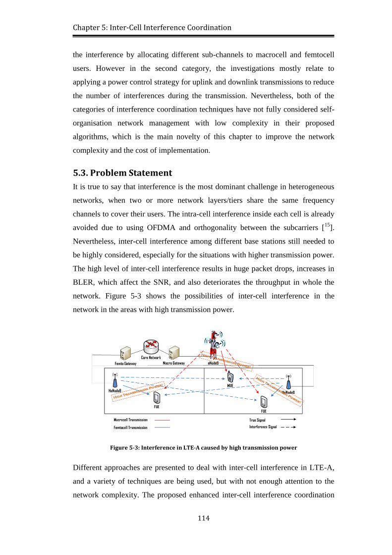
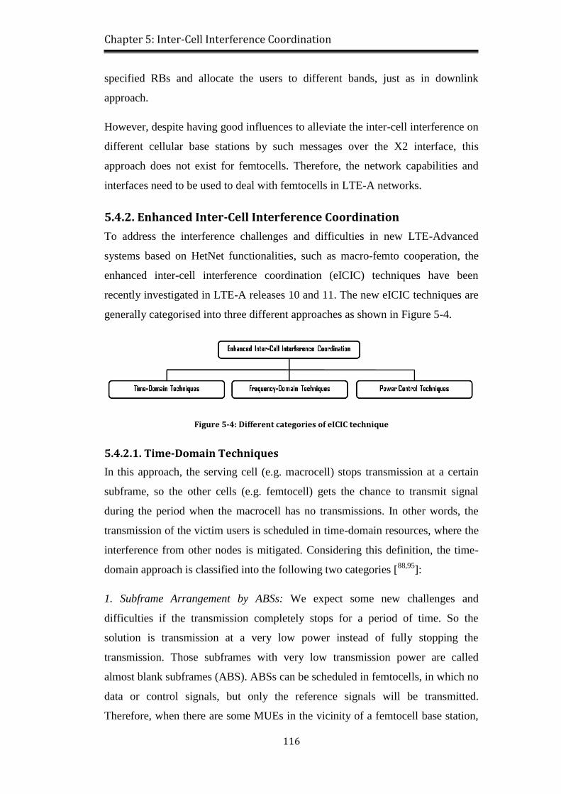
Figure 5-3: Interference in LTE-A caused by high transmission power ............. 114
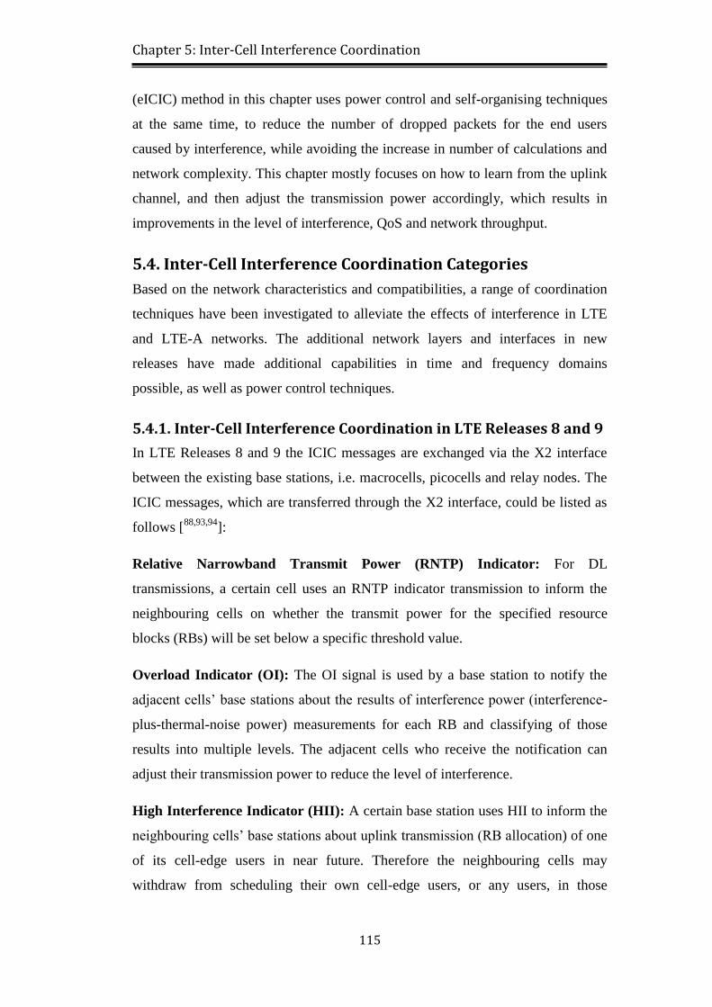
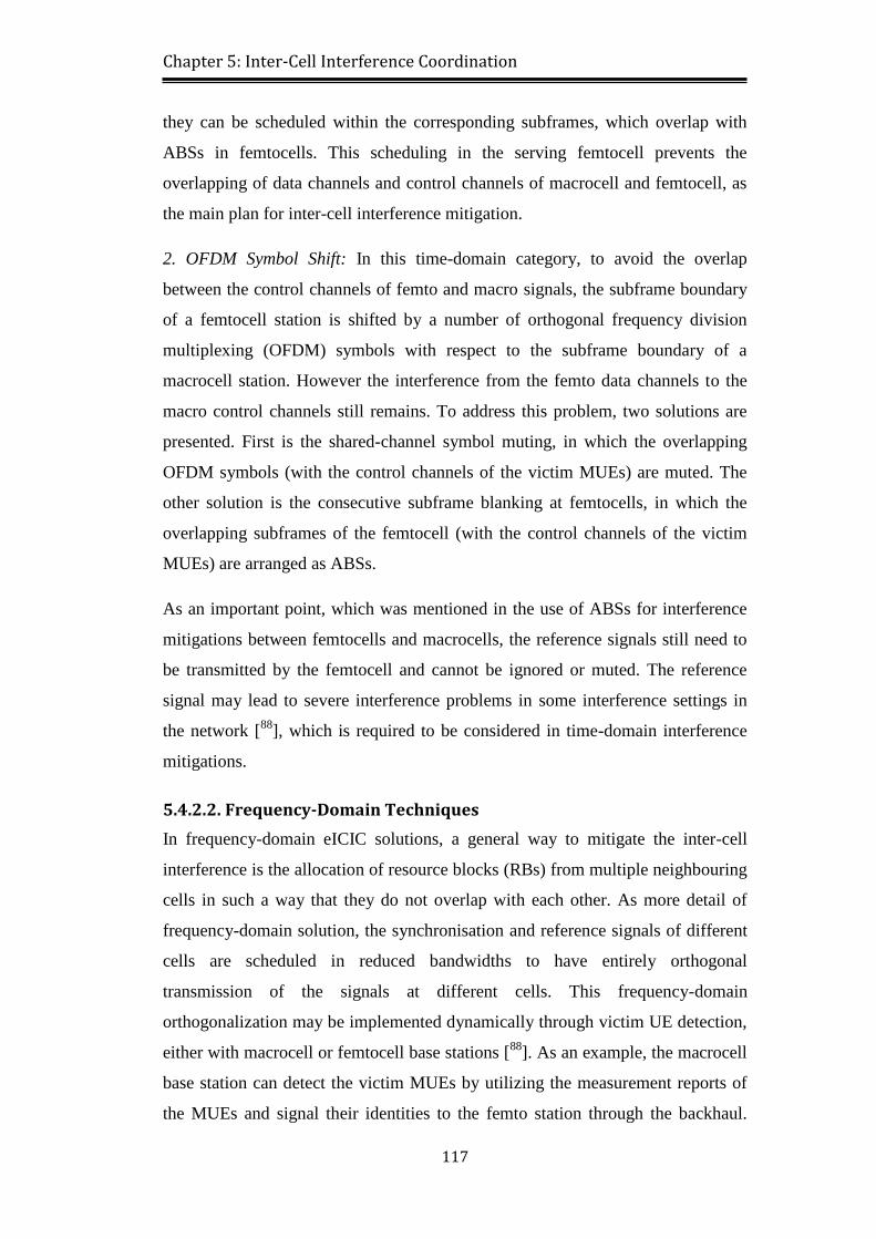
Figure 5-4: Different categories of eICIC technique .......................................... 116
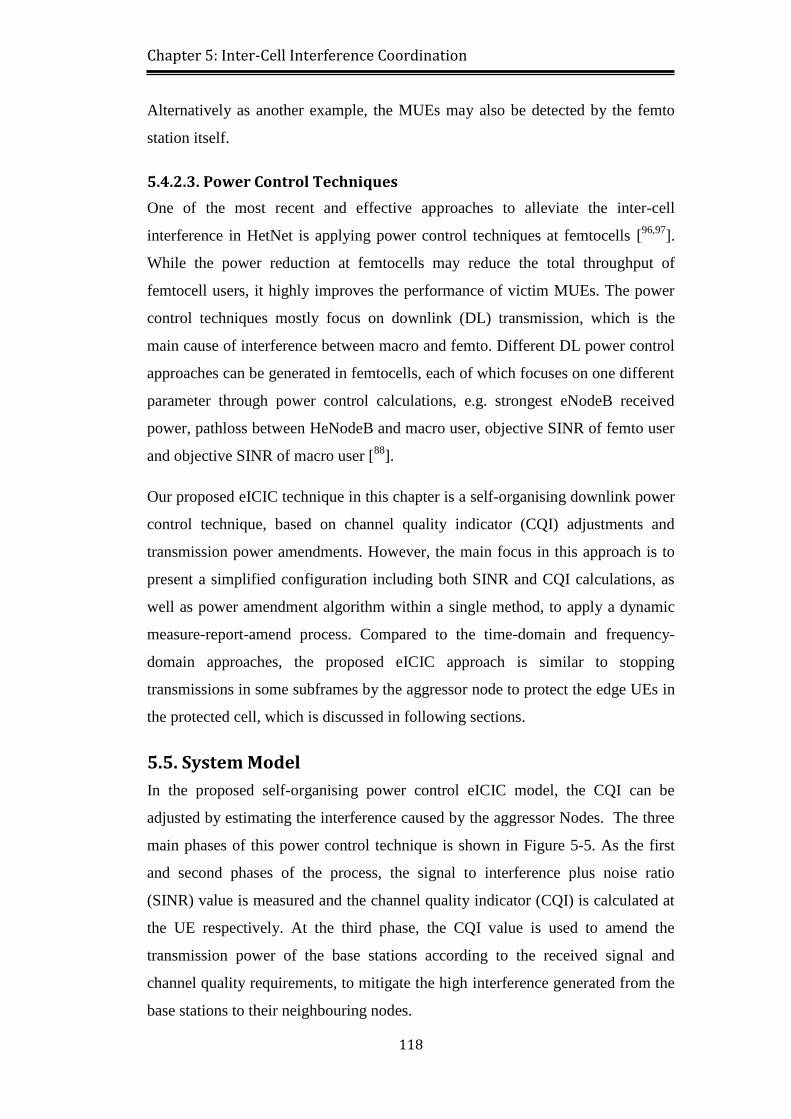
Figure 5-5: Main phases of the eICIC with power control ................................. 119
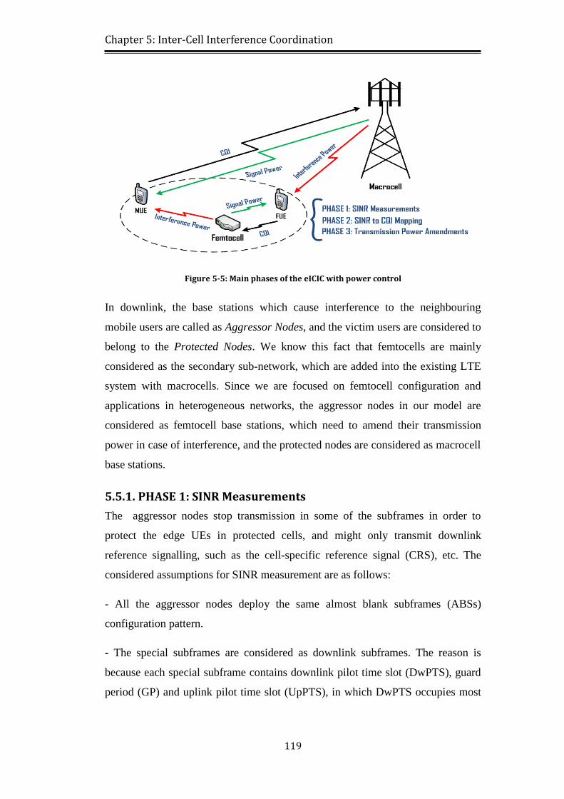
Figure 5-6: Subframe structure and SINR in different cell types ....................... 120
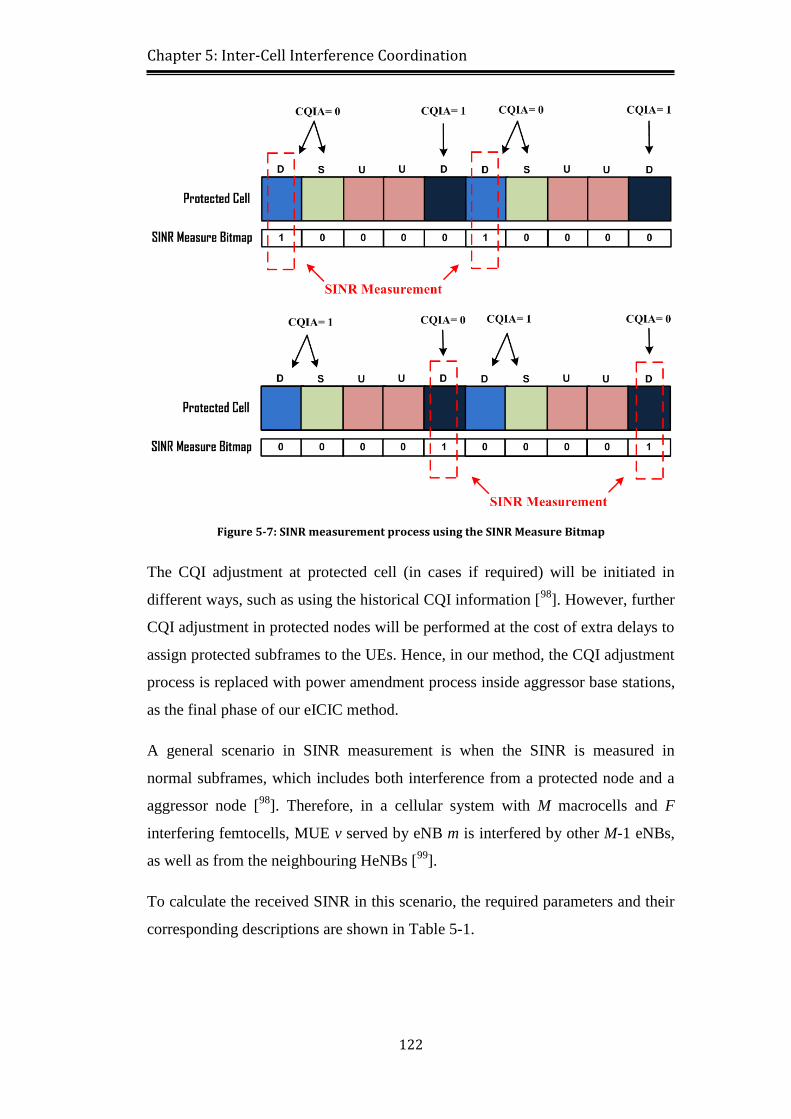
Figure 5-7: SINR measurement process using the SINR Measure Bitmap ........ 122
Figure 5-8: Self-organising power control algorithm based on CQI report ........ 127
Figure 5-9: Self-organising power control implementation ................................ 128
Figure 5-10: LTE-A simulation platform in OPNET for power control ............. 130
Figure 5-11: Transceiver pipeline model in OPNET .......................................... 132
Figure 5-12: SINR calculation process in UE Rx pipeline stages ...................... 133
Figure 5-13: Simulation time sequences of packet transmission in OPNET ...... 134
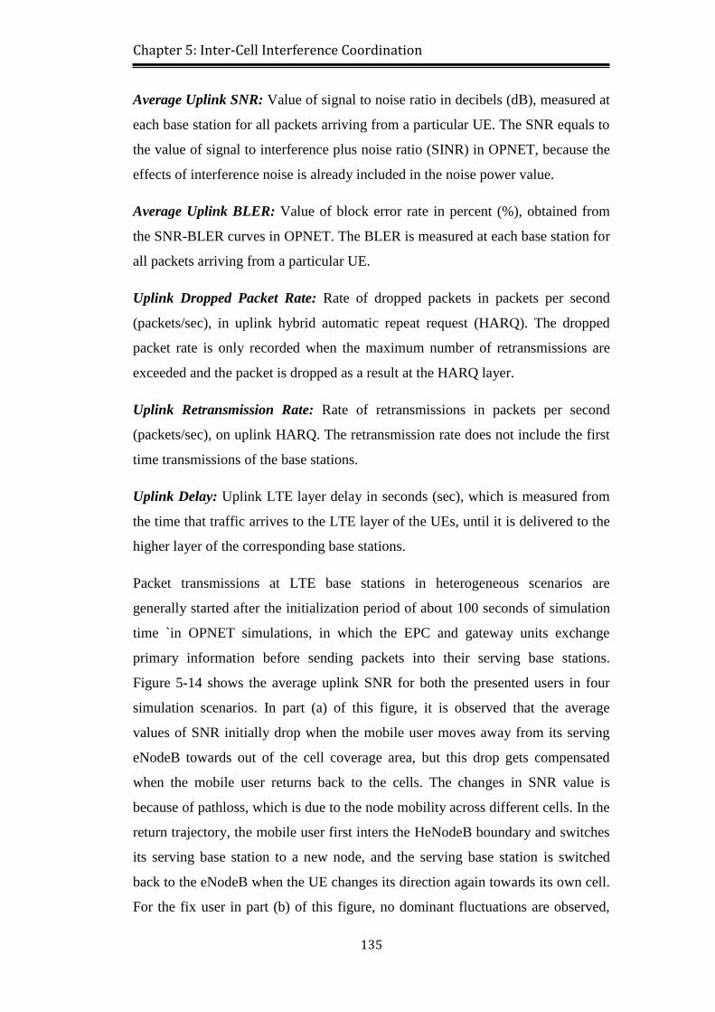
Figure 5-14: Average uplink SNR for (a) mobile user, (b) fix user .................... 136
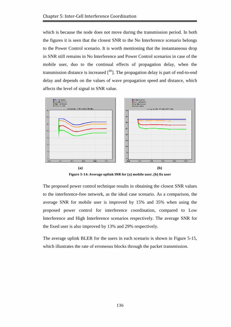
Figure 5-15: Average uplink BLER for (a) mobile user, (b) fix user ................. 137
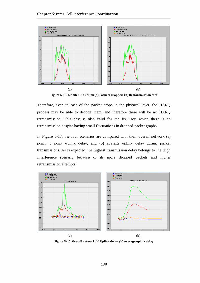
Figure 5-16: Mobile UE’s uplink (a) Packets dropped, (b) Retransmission rate 138
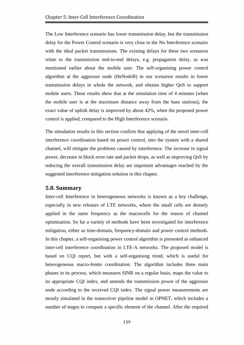
Figure 5-17: Overall network (a) Uplink delay, (b) Average uplink delay ........ 138
Page 16
xvi
List of Tables
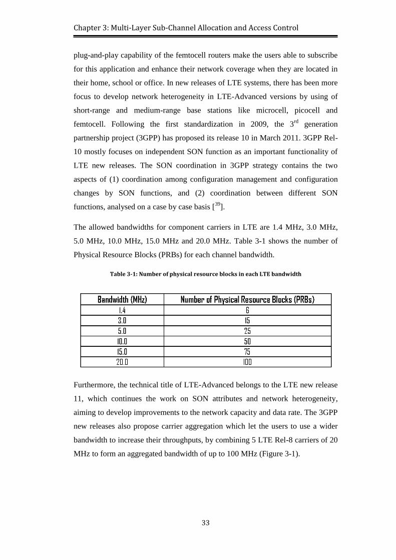
Table 3-1: Number of physical resource blocks in each LTE bandwidth ............. 33
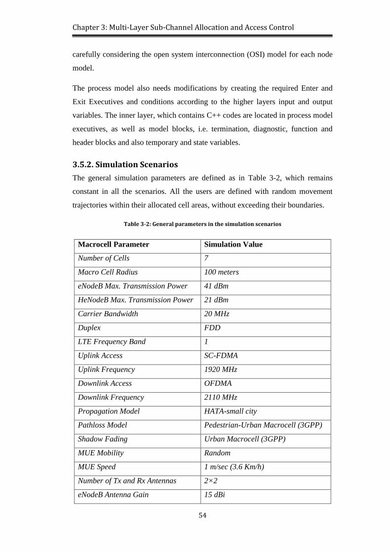
Table 3-2: General parameters in the simulation scenarios .................................. 54
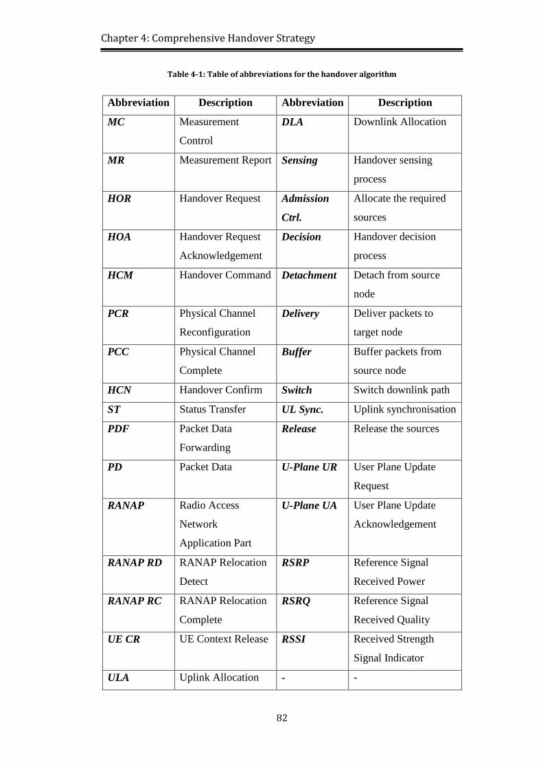
Table 4-1: Table of abbreviations for the handover algorithm ............................. 82
Table 4-2: Pre-defined UE residence states for different speed ranges ................ 89
Table 4-3 The handover sessions parameters and values ..................................... 91
Table 4-4: Major parameters and definitions for 3D Markov Chain .................... 92
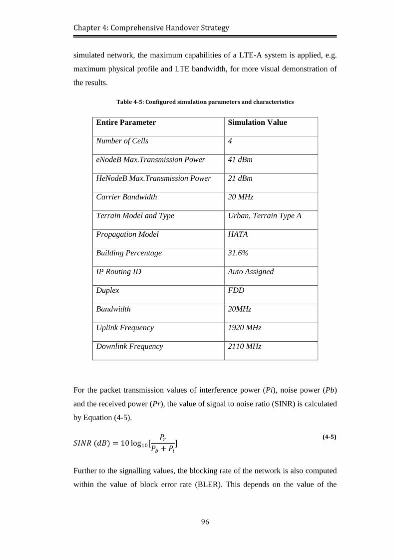
Table 4-5: Configured simulation parameters and characteristics ........................ 96
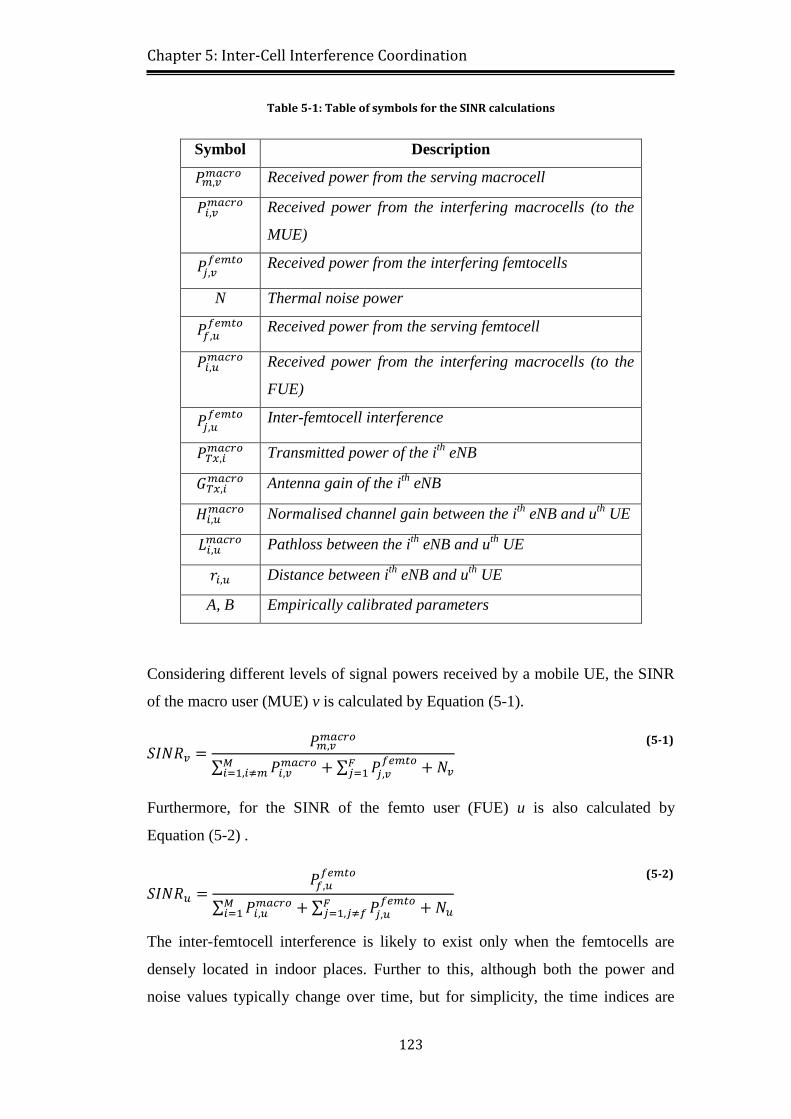
Table 5-1: Table of symbols for the SINR calculations ...................................... 123
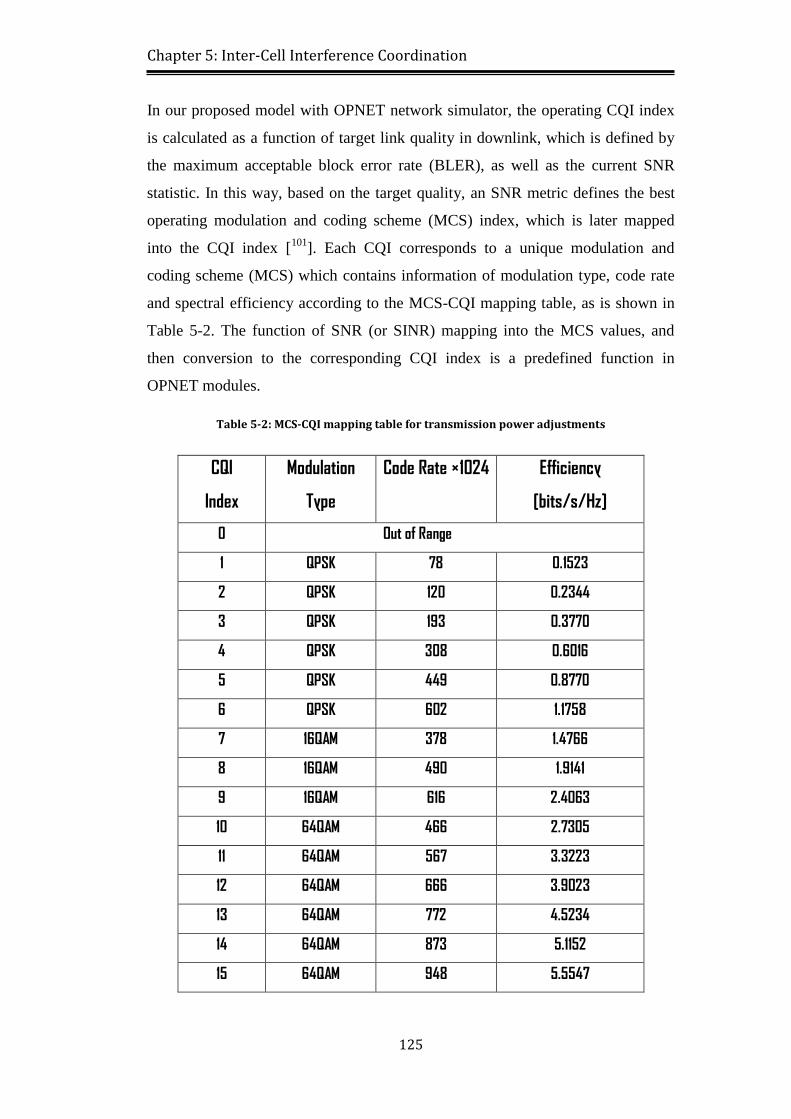
Table 5-2: MCS-CQI mapping table for transmission power adjustments ......... 125
Table 5-3: Simulation parameters for power control algorithm ......................... 129
Page 17
xvii
List of Abbreviations
Abbreviation Stands for
ABS Almost Blank Subframe
ACAE Auto-Correlation based Advance Energy
ADSL Asymmetric Digital Subscriber Line
AP Access Point
ARP Address Resolution Protocol
AS Access Stratum
ASE Area Spectral Efficiency
BLER Block Error Rate
BS Base Station
BTS Base Transceiver Station
CA Carrier Aggregation
CAC Call Admission Control
CAPEX Capital Expenditure
CC Component Carrier
CDMA Code division multiple Access
CI Confidence Interval
CLT Central Limit Theorem
CoMP Cooperative Multi-Point
CPU Central Processing Unit
CQI Channel Quality Indicator
CQIA Channel Quality Indicator Adjust
CRS Cell-Specific Reference Signal
CSG Closed Subscriber Group
CT Cooperative Transmission
DFT Discrete Fourier Transform
DL Downlink
DLA Downlink Allocation
DSA Dynamic Spectrum Allocation
Page 18
xviii
DSCP Differentiated Services Code Point
DSL Digital Subscriber Line
DVB Digital Video Broadcasting
DwPTS Downlink Pilot Time Slot
D2D Device-to-Device
EDGE Enhanced Data for Global Evolution
EESM Effective Exponential SNR Mapping
EF Expedited Forwarding
E-GPRS Enhanced GPRS
eICIC Enhanced Inter-Cell Interference Coordination
eNB Evolved Node-B
eNodeB Evolved Node-B
EPC Evolved Packet Core
EPS Evolved Packet System
E-UTRAN Evolved Universal Terrestrial Radio Access Network
EV-DO Evolution-Data Optimised
FAP Femtocell Access Point
FDCH Femto Data Channel
FDD Frequency Division Duplex
FFR Fractional Frequency Reuse
FMC Fixed Mobile Convergence
FoMP Femto over Macro Priority
FTP File Transfer Protocol
GBR Guaranteed Bit Rate
GPRS General Packet Radio Service
GSM Global System for Mobile Communications
GSM EFR Global System for Mobile Coms. Enhanced Full Rate
GTP GPRS Tunnelling Protocol
GW Gateway
HA Handover Acknowledgement
HARQ Hybrid Automatic Repeat Request
HCM Handover Command
HCN Handover Confirm
Page 19
xix
HDCT Hybrid Division Cooperative Transmission
HeNB Home Evolved Node-B
HeNodeB Home Evolved Node-B
HetNet Heterogeneous Network
HFFR Hybrid Fractional Frequency Reuse
HHT Handover Hysteresis Threshold
HII High Interference Indicator
HO Handover
HOA Handover Request Acknowledgement
HOR Handover Request
HSCSD High-Speed Circuit-Switched Data
HSPA High Speed Packet Access
HSS Home Subscriber Service
HTTP Hypertext Transfer Protocol
ICIC Inter-Cell Interference Coordination
iDEN Integrated Digital Enhanced Network
IDFT Inverse Discrete Fourier Transform
iMode Idle Mode
IMT-Advanced International Mobile Telecommunications-Advanced
IP Internet Protocol
IS Interim Standard
ISM Industrial, Scientific and Medical
ITU International Telecommunication Union
LTE Long Term Evolution
LTE-A Long Term Evolution-Advanced
MAC Medium Access Control
MC Measurement Control
MCS Modulation and Coding Scheme
MDCH Macro Data Channel
MeNodeB Macro Evolved Node-B
MIMO Multiple Input Multiple Output
MME Mobility Management Entity
MNO Mobile Network Operator
Page 20
xx
MPDU MAC Protocol Data Unit
MR Measurement Report
MS Mobile Station
MU Mobile User
MUE Mobile User Equipment
M2M Machine-to-Machine
NAS Non-Access Stratum
NEM Network Element Management
OFDM Orthogonal Frequency Division Multiplexing
OFDMA Orthogonal Frequency Division Multiple Access
OI Overload Indicator
OLPC Open Loop Power Control
OPEX Operational Expenditure
OSFFR Optimal Static Fractional Frequency Reuse
OSG Open Subscriber Group
OSI Open System Interconnection
PAPR Peak to Average Power Ratio
PCC Physical Channel Complete
PCID Physical Cell Identity
PCR Physical Channel Reconfiguration
PCRF Policy and Charging Rules Function
PD Packet Data
PDC Personal Digital Cellular
PDCP Packet Data Convergence Protocol
PDF Packet Data Forwarding
PDN-GW Packet Data Network Gateway
PDU Protocol Data Unit
PPP Point-to-Point Protocol
PRB Physical Resource Block
QAM Quadrature Amplitude Modulation
QoS Quality of Service
QPSK Quadrature Phase Shift Keying
RA Resource Availability
Page 21
xxi
RAN Radio Access Network
RANAP Radio Access Network Application Part
RANAP RC RANAP Relocation Complete
RANAP RD RANAP Relocation Detect
RB Resource Block
RF Radio Frequency
RN Relay Node
RNC Radio Network Controller
RNTP Relative Narrowband Transmit Power
RoF Radio over Fibre
RS Relay Station
RSRP Reference Signal Received Power
RSRQ Reference Signal Received Quality
RSSI Received Signal Strength Indicator
Rx Receiver
SC-FDMA Single Carrier Frequency Division Multiple Access
SCTP Stream Control Transmission Protocol
SDU Service Data Unit
S-GW Serving Gateway
SINR Signal to Interference plus Noise Ratio
SNR Signal to Noise Ratio
SON Self-Organising Network
SONET Synchronous Optical Networking
ST Status Transfer
TCP Transmission Control Protocol
TDA Transmission Data Attribute
TDD Time Domain Duplex
TP Transmission Power
TPAL Transport Protocol Adaptation Layer
Tx Transmitter
UDP User Datagram Protocol
UE User Equipment
UE CR UE Context Release
Page 22
xxii
UL Uplink
ULA Uplink Allocation
ULPC Uplink Power Control
UMTS Universal Mobile Telecommunications System
U-Plane UA User Plane Update Acknowledgement
U-Plane UR User Plane Update Request
UpPTS Uplink Pilot Time Slot
VoIP Voice over Internet Protocol
WiMAX Worldwide Interoperability for Microwave Access
WLAN Wireless Local Area Network
1G First Generation
3D Three Dimensional
3GPP Third Generation Partnership Project
4G Fourth Generation
Page 23
xxiii
List of Symbols
Symbol Description Unit
𝑐 Ratio of handover regions
𝐺 Antenna gain Decibel-isotropic (dBi)
𝑔𝑘 Total available resource blocks
𝐻 Normalised channel gain Decibel (dB)
𝐿 Pathloss Decibel (dB)
𝑁 Thermal noise power Decibel-milliwatt(dBm)
𝑃𝑏 Noise power Watt (w)
𝑃𝑖 Interference power Watt (w)
𝑃𝑟 Received transmission power Watt (w)
𝑟 Distance between base st. and mobile user Meter (m)
RSRPk Ref. signal received power from the kth
cell Watt (w)
𝑠 Standard deviation Same unit as the data
𝑆𝐸𝑥͞ Standard error Same unit as the data
𝑆𝐼𝑁𝑅 Signal to interference plus noise ratio Decibel (dB)
𝑇 Traffic intensity
𝑥͞ Mean value of 𝑥͞ Same unit as 𝑥͞
𝛼 Handover rate
𝛽𝑖 Resource blocks consumed by the ith
user
µ Handover service rate
𝜆 Handover session rate
𝜙 Total number of resource blocks
Page 24
Chapter 1: Introduction
1
Chapter 1 Introduction
1.1. Cellular Network Evolution
A cellular network is defined as a wireless network which includes terrain areas
called as cells, in which each individual cell is served by at least one fixed
transceiver, called as base station (BS). To guarantee the bandwidth, as well as
avoiding interference between the cells, each cell normally uses a different set of
frequencies than the neighbouring cells. A cellular network provides a wide area
coverage for different sorts of fixed and portable transceivers, e.g. mobile phones,
tablets, etc. over a pre-defined geographic area supported by network providers.
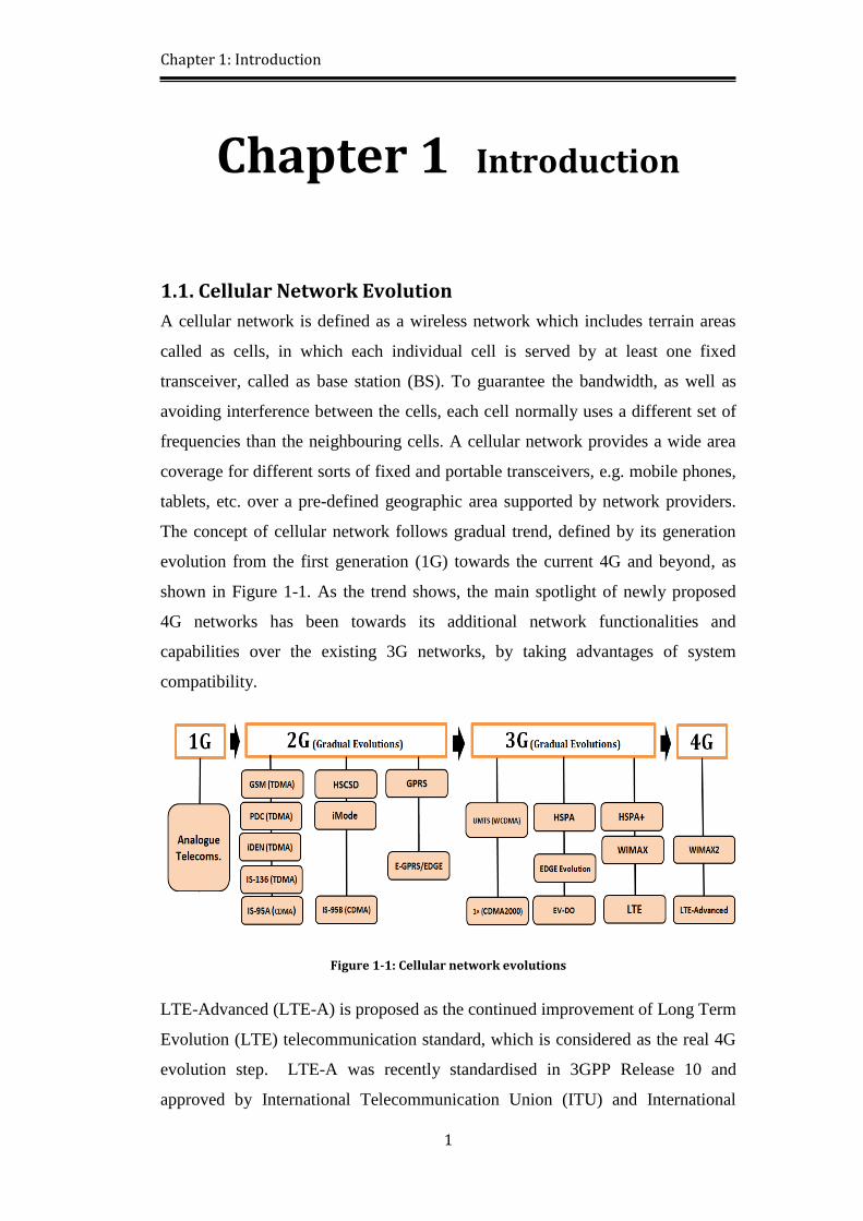
The concept of cellular network follows gradual trend, defined by its generation
evolution from the first generation (1G) towards the current 4G and beyond, as
shown in Figure 1-1. As the trend shows, the main spotlight of newly proposed
4G networks has been towards its additional network functionalities and
capabilities over the existing 3G networks, by taking advantages of system
compatibility.
Figure 1-1: Cellular network evolutions
LTE-Advanced (LTE-A) is proposed as the continued improvement of Long Term
Evolution (LTE) telecommunication standard, which is considered as the real 4G
evolution step. LTE-A was recently standardised in 3GPP Release 10 and
approved by International Telecommunication Union (ITU) and International
Page 25
Chapter 1: Introduction
2
Mobile Telecommunications-Advanced (IMT-Advanced) to be implemented over
the existing LTE systems [1-3
].
The significant prospect of this evolution is to approach to higher data rates
specifically in congested areas, whilst facing the least possible network
interference. For such telecommunication standards and networks, the main
expectations could be summarised by three constraints: data rate, delay and
capacity. 3GPP defines the increased peak data rate for LTE-Advanced to be
3Gbps in downlink and 1.5Gbps in uplink, by adopting multiple input multiple
output (MIMO) and orthogonal frequency division multiplexing (OFDM)
techniques. Delay could also be assumed as a principal target to reduce the latency
for a packet sent from a server to clients. With growing demands, the resultant
capacity shortage would degrade the quality of service (QoS) for the overall
network, and therefore appropriate methods are essential to measure and manage
spectral efficiency requirements. Interference is a critical factor which affects the
entire key attributes by degrading network performances and expectations.
On the other hand, self-organisation network (SON) has been recently
investigated as a reconfigurable networking technology to improve the spectrum
efficiency for the wireless access technologies, such as LTE and Radio over Fibre
(RoF). A self-organising strategy is basically known for its internal coordination
and interactions among its elements within different stages, which could promote
self-awareness, self-configuration and demand-base-architecture within an entire
network. Therefore, the networks would be capable of adapting themselves to
obtain more efficient communication, while taking into account the end-to-end
goals. The currently available unlicensed spectrum is reaching its limits, while
there are lots of demands for the wireless access and applications. Hence, the
intelligent use of spectrum is urgently required to avoid the latency and
difficulties in broadband communications, caused by the frequency interference
through the networks. Critical enhancements are necessary to be applied on the
existing LTE networks, which could improve the cellular interference during the
spectrum usage. Therefore, novel approaches could fulfil network requirements
by use of self-organising transceivers, and provide the anticipated capacity and
quality of service for network subscribers [1].
Page 26
Chapter 1: Introduction
3
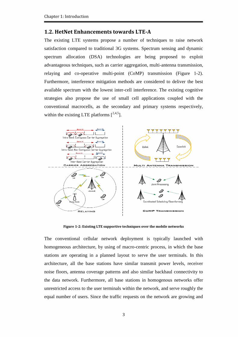
1.2. HetNet Enhancements towards LTE-A
The existing LTE systems propose a number of techniques to raise network
satisfaction compared to traditional 3G systems. Spectrum sensing and dynamic
spectrum allocation (DSA) technologies are being proposed to exploit
advantageous techniques, such as carrier aggregation, multi-antenna transmission,
relaying and co-operative multi-point (CoMP) transmission (Figure 1-2).
Furthermore, interference mitigation methods are considered to deliver the best
available spectrum with the lowest inter-cell interference. The existing cognitive
strategies also propose the use of small cell applications coupled with the
conventional macrocells, as the secondary and primary systems respectively,
within the existing LTE platforms [2,4,5
].
Figure 1-2: Existing LTE supportive techniques over the mobile networks
The conventional cellular network deployment is typically launched with
homogeneous architecture, by using of macro-centric process, in which the base
stations are operating in a planned layout to serve the user terminals. In this
architecture, all the base stations have similar transmit power levels, receiver
noise floors, antenna coverage patterns and also similar backhaul connectivity to
the data network. Furthermore, all base stations in homogenous networks offer
unrestricted access to the user terminals within the network, and serve roughly the
equal number of users. Since the traffic requests on the network are growing and
Page 27
Chapter 1: Introduction
4
the radio frequency (RF) environment is being changed, additional sub-carriers
are required to overcome the capacity and link resource limitations [1,6
].
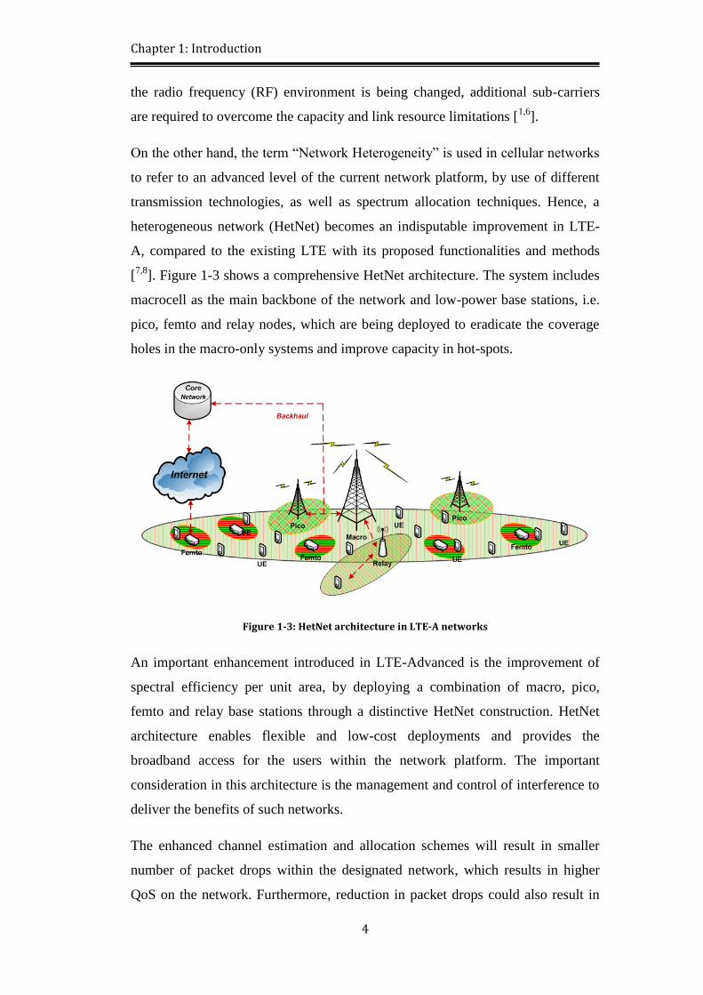
On the other hand, the term “Network Heterogeneity” is used in cellular networks
to refer to an advanced level of the current network platform, by use of different
transmission technologies, as well as spectrum allocation techniques. Hence, a
heterogeneous network (HetNet) becomes an indisputable improvement in LTE-
A, compared to the existing LTE with its proposed functionalities and methods
[7,8
]. Figure 1-3 shows a comprehensive HetNet architecture. The system includes
macrocell as the main backbone of the network and low-power base stations, i.e.
pico, femto and relay nodes, which are being deployed to eradicate the coverage
holes in the macro-only systems and improve capacity in hot-spots.
Figure 1-3: HetNet architecture in LTE-A networks
An important enhancement introduced in LTE-Advanced is the improvement of
spectral efficiency per unit area, by deploying a combination of macro, pico,
femto and relay base stations through a distinctive HetNet construction. HetNet
architecture enables flexible and low-cost deployments and provides the
broadband access for the users within the network platform. The important
consideration in this architecture is the management and control of interference to
deliver the benefits of such networks.
The enhanced channel estimation and allocation schemes will result in smaller
number of packet drops within the designated network, which results in higher
QoS on the network. Furthermore, reduction in packet drops could also result in
Page 28
Chapter 1: Introduction
5
obtaining higher data traffic throughput, as well as higher signal to noise ratio
(SNR) in transmission, which aims to obtain a better quality of received signal
within the designated network [1,2
]. For indoor applications, the macro base
stations need to boost their transmission power to cover their indoor users, which
may result in a serious inter-cell interference and degradation in network
performance. Implementing femtocells -as a good instance for indoor
applications- to cover the indoor spaces provides quality cellular services by
increasing the network capacity. This idea also allows the operators to offload
significant amounts of traffic away from the existing macrocell network thereby
satisfying more macrocell users. According to the recent research in network
financial issues, it has been estimated that the traffic offload from the central
macrocell to femtocells can decrease the costs for the network operators by up to
70% [9].
1.3. Self-Organising Attitudes
Self-Organising Network (SON) methodologies [10-12
] are introduced to reduce
the operational expenditure for the network operators. As a good example, the
interference coordination is an important concept of SON. The inter-cell
interference is one of the main challenges in orthogonal frequency division
multiple access (OFDMA)-based networks, especially in downlink, where the
broadband services exist. In this context, the coordinated usage of the network
resources in related cells can be an effective SON approach to maximise the
efficiency of the bandwidth. The intra-cell orthogonality between the users in both
LTE uplink and downlink leads to only consider the inter-cell interference as the
main interference source in this network, which could also affect the frequency
reuse at the cell boundaries [13
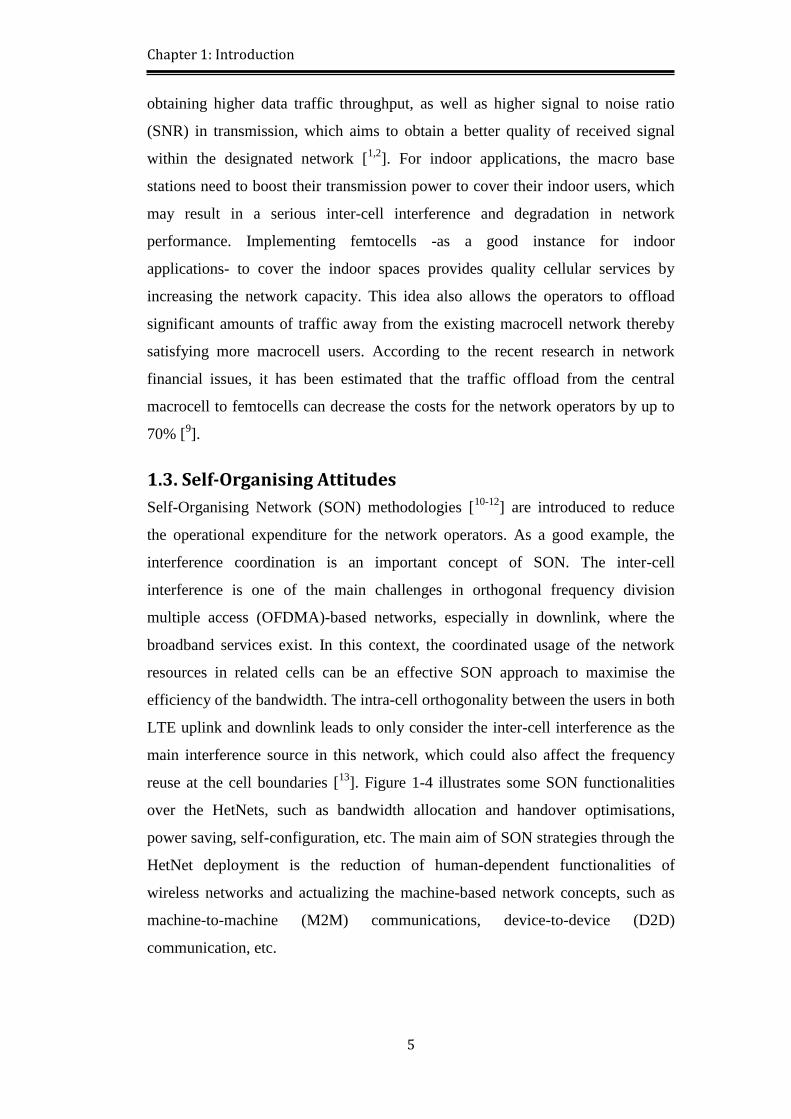
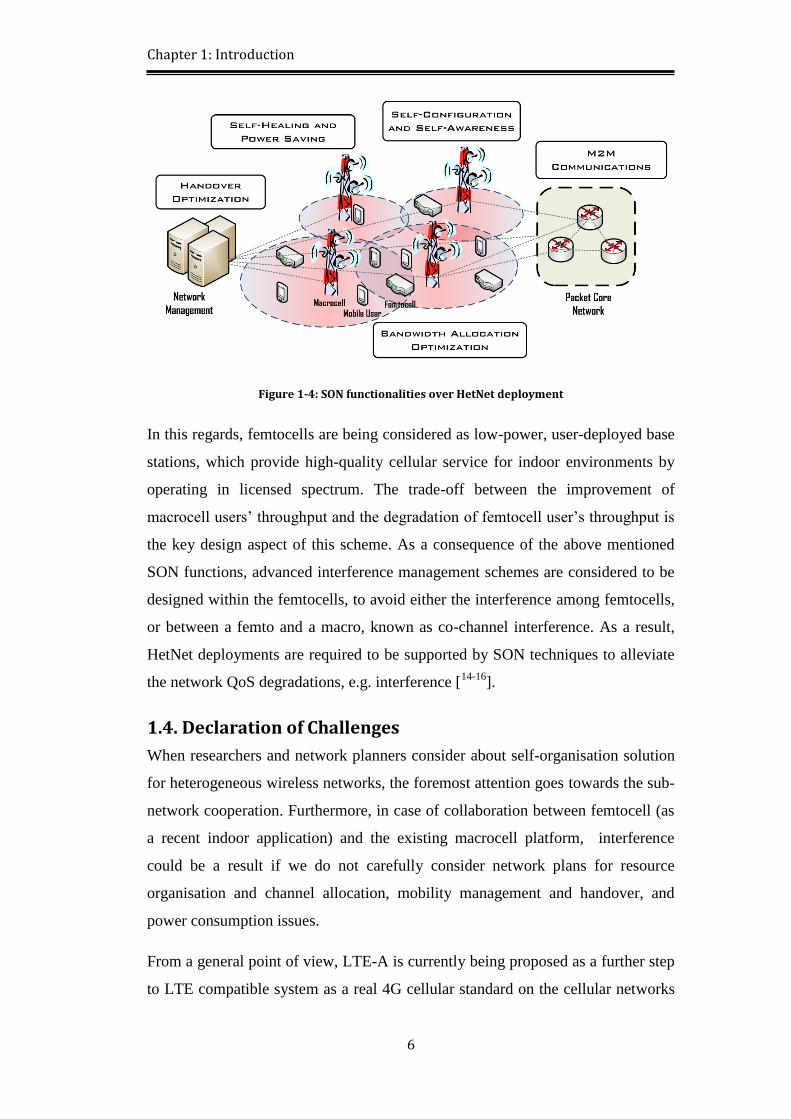
]. Figure 1-4 illustrates some SON functionalities
over the HetNets, such as bandwidth allocation and handover optimisations,
power saving, self-configuration, etc. The main aim of SON strategies through the
HetNet deployment is the reduction of human-dependent functionalities of
wireless networks and actualizing the machine-based network concepts, such as
machine-to-machine (M2M) communications, device-to-device (D2D)
communication, etc.
Page 29
Chapter 1: Introduction
6
Figure 1-4: SON functionalities over HetNet deployment
In this regards, femtocells are being considered as low-power, user-deployed base
stations, which provide high-quality cellular service for indoor environments by
operating in licensed spectrum. The trade-off between the improvement of
macrocell users’ throughput and the degradation of femtocell user’s throughput is
the key design aspect of this scheme. As a consequence of the above mentioned
SON functions, advanced interference management schemes are considered to be
designed within the femtocells, to avoid either the interference among femtocells,
or between a femto and a macro, known as co-channel interference. As a result,
HetNet deployments are required to be supported by SON techniques to alleviate
the network QoS degradations, e.g. interference [14-16
].
1.4. Declaration of Challenges
When researchers and network planners consider about self-organisation solution
for heterogeneous wireless networks, the foremost attention goes towards the sub-
network cooperation. Furthermore, in case of collaboration between femtocell (as
a recent indoor application) and the existing macrocell platform, interference
could be a result if we do not carefully consider network plans for resource
organisation and channel allocation, mobility management and handover, and
power consumption issues.
From a general point of view, LTE-A is currently being proposed as a further step
to LTE compatible system as a real 4G cellular standard on the cellular networks
Page 30
Chapter 1: Introduction
7
evolution trend. Alongside the increasing demand in mobile networks, the
customers’ satisfaction with a ubiquitous heterogeneous network is going to be
the main challenge for the network operators. Hence, planning a multi-layer
network with diverse range of base stations seems to be an appropriate solution
for this deficiency in the first instance [1,14
]. However, the cellular network
evolution requires revised strategies to keep the network’s quality of service,
while trying to satisfy the increasing demands of subscribers. SON policy is
therefore introduced and planned as a fitting approach to reduce the network
hardware (e.g. supportive macro base stations, etc.), transmission complexity,
implementation costs, etc., and to improve the quality of reception and
transmission within LTE-A.
The interference mitigation plan is necessary to having an optimised bandwidth
allocation for various classes of the network users, specifically when the
bandwidth is shared between the network layers. Therefore, applying the SON
strategy as a part of LTE-A new releases is a novel strategy to improve the
network satisfaction by increasing network capacity, while mitigating the inter-
cell interference. This could be completed by using internal communications
among the macro and neighbouring base stations, inside the cellular LTE-A
network. This thesis addresses new SON algorithms to be inserted into the
existing HetNet LTE protocols and system algorithms, which could be considered
for the expected network.
1.5. Research Aim and Objectives
The main aim of this thesis is expressed as developing a self-organising based
methodology for new releases of heterogeneous LTE-Advanced networks to
simultaneously improve both capacity and quality of service. The main keywords
of this research could be expressed as (but not limited to): SON; HetNet; LTE-A;
Femtocell; Multi-Layer; Interference; Access Control; Handover; eICIC;
Power Control. The self-organising approach of this research is defined as the
main target, to be obtained through the following objectives:
1. The first objective of the thesis focuses on coordinated resource allocation by
applying self-organising methodologies. The efficient frequency reuse is proposed
among macro and femto sub-networks, to apply bandwidth optimisation for the
Page 31
Chapter 1: Introduction
8
multiple access cellular networks. The novel dynamic bandwidth allocation
technique is planned over a unique algorithm to apply resource allocation for
diverse base stations, by sharing the total accessible spectrum. The proposed
resource optimisation technique boosts network throughput and reduces network
complexity, while saving a significant fraction of the available resources within
the entire network.
2. The second objective is to fulfil the mobility management requirements within
the coordinated LTE-A network. This target is approached by proposing of a
novel handover algorithm, which exploits the existing network mobility
parameters. The novel handover strategy is introduced as a comprehensive
algorithm, because it includes multiple controls -called as “checks”- to optimise
the handover process, as well as avoid unnecessary handovers. The multi-check
strategy contains a hierarchical algorithm to test the power and quality of the
received signal, bandwidth availability, user residence duration and femtocell
priorities over the macro stations. This algorithm is expected to meet the handover
quality requirements, while avoiding unnecessary handovers.
3. The third objective of this research directly focuses on inter-cell interference
mitigation based on power control techniques. The enhanced inter-cell
interference coordination (eICIC) algorithm is designed based on downlink power
reception among macro and femto sub-networks. To approach this target, self-
organising power cooperation is introduced to be deployed between macro and
femto stations. The novel eICIC algorithm reduces the overall interference, as
well as improving the performance of victim mobile users, by adapting network
transmission power.
1.6. Novel Research Contributions
This research introduces, evaluates and recommends new self-organising network
management for HetNet LTE-A networks. The self-organisation methodology of
this work is exploited by its various novel techniques to deal with bandwidth
allocation, mobility management and interference mitigation. The main
contribution chapters of this thesis are represented on Figure 1-5. The self-
organising strategy is considered as the main methodology of the work to support
Page 32
Chapter 1: Introduction
9
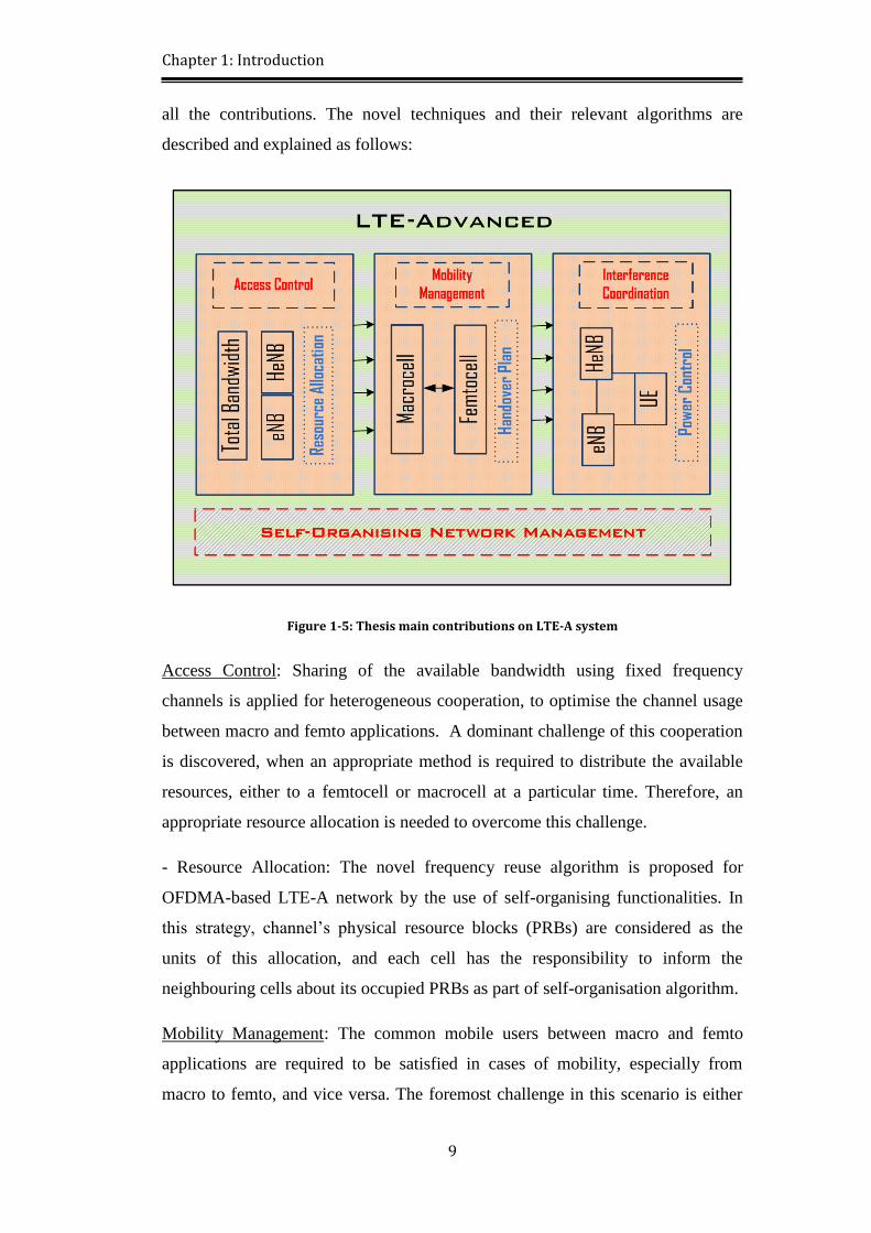
all the contributions. The novel techniques and their relevant algorithms are
described and explained as follows:
Figure 1-5: Thesis main contributions on LTE-A system
Access Control: Sharing of the available bandwidth using fixed frequency
channels is applied for heterogeneous cooperation, to optimise the channel usage
between macro and femto applications. A dominant challenge of this cooperation
is discovered, when an appropriate method is required to distribute the available
resources, either to a femtocell or macrocell at a particular time. Therefore, an
appropriate resource allocation is needed to overcome this challenge.
- Resource Allocation: The novel frequency reuse algorithm is proposed for
OFDMA-based LTE-A network by the use of self-organising functionalities. In
this strategy, channel’s physical resource blocks (PRBs) are considered as the
units of this allocation, and each cell has the responsibility to inform the
neighbouring cells about its occupied PRBs as part of self-organisation algorithm.
Mobility Management: The common mobile users between macro and femto
applications are required to be satisfied in cases of mobility, especially from
macro to femto, and vice versa. The foremost challenge in this scenario is either
Page 33
Chapter 1: Introduction
10
the omission of handovers, or facing unnecessary handovers during this process
due to having inaccurate channel estimations to begin the handover process.
Consequently, correct handover plan is required to plan an intelligent handover
strategy.
- Handover Plan: An efficient handover plan is used by introducing a novel
handover algorithm, based on self-organising communications. The proposed
multi-check plan considers more accurate calculations in the handover initiation
stage, while avoiding unnecessary handovers through the system.
Interference Coordination: Using of same frequency channel by both sub-
networks is expected to produce higher levels of inter-cell interference. Hence, as
a dominant challenge, network cooperation requires interference mitigation
schemes to deliver smooth signals to the end users. Therefore, enhanced ICIC
(eICIC) solution is introduced based on power control functionalities, for
interference alleviation in macro-femto transmissions.
- Power Control: The novel power control algorithm is inserted into femto
stations’ functional blocks within the self-organising power balance algorithm.
The power control technique focuses on downlink transmission, as the main link
of interference between macro and femto sub-networks in LTE-A.
1.7. Methodology
The necessity of hardware implementation and expenditure is growing by cellular
network evolutions. This matter has been the biggest motivation for this thesis to
emphasise self-organising solutions for such sub-systems cooperation challenges
in LTE-Advanced. The hierarchical SON trend in this work begins from the
channel allocation issues as the first challenge, moves toward the mobility
management concerns for the mobile nodes, and ends by the interference
management resolution. In this PhD thesis, each of the proposed challenges are
introduced and discussed in detail, followed by the problem formulation and
solution inside the contribution chapters. This research is based on network
simulations, as well as a literature review about the existing research work to
identify the delivered novelty, compared to the identified relevant works. Since
the analysis and modifications for the proposed new algorithms are for different
Page 34
Chapter 1: Introduction
11
layers in the open system interconnection (OSI) model, OPNET modeler network
simulator has been used as the most appropriate software for our simulations.
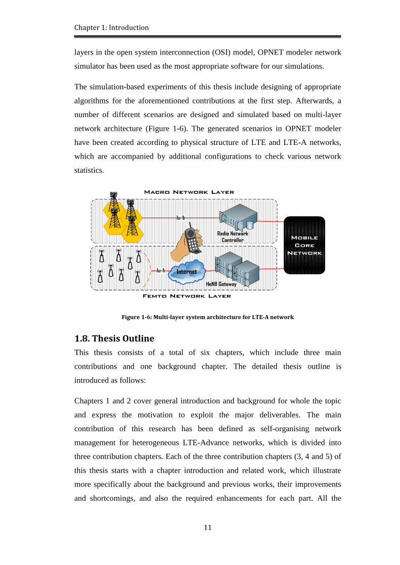
The simulation-based experiments of this thesis include designing of appropriate
algorithms for the aforementioned contributions at the first step. Afterwards, a
number of different scenarios are designed and simulated based on multi-layer
network architecture (Figure 1-6). The generated scenarios in OPNET modeler
have been created according to physical structure of LTE and LTE-A networks,
which are accompanied by additional configurations to check various network
statistics.
Figure 1-6: Multi-layer system architecture for LTE-A network
1.8. Thesis Outline
This thesis consists of a total of six chapters, which include three main
contributions and one background chapter. The detailed thesis outline is
introduced as follows:
Chapters 1 and 2 cover general introduction and background for whole the topic
and express the motivation to exploit the major deliverables. The main
contribution of this research has been defined as self-organising network
management for heterogeneous LTE-Advance networks, which is divided into
three contribution chapters. Each of the three contribution chapters (3, 4 and 5) of
this thesis starts with a chapter introduction and related work, which illustrate
more specifically about the background and previous works, their improvements
and shortcomings, and also the required enhancements for each part. All the
Page 35
Chapter 1: Introduction
12
contribution chapters end with a chapter summary and references, to help the
readers in finding the relevant outcomes and resources for each method. Chapter 6
makes an overall conclusion of the thesis, discussion about the area of research
and future work for further improvements and assessment of the potential
influence of this thesis for new releases of LTE-Advanced networks, based on
SON functionalities.
Page 36
Chapter 2: Technical Background in LTE-A and SON Management
13
Chapter 2 Technical
Background in LTE-A and SON
Management
The LTE and LTE-A cellular network systems are enhanced with a number of
techniques to provide capacity and quality of service. The co-existence of both
macro and femto nodes need to be carefully designed while considering the
foreseen transmission challenges. It is also important before starting of any
investigations in this field to become more familiar with the network backbone, as
well as preliminary information about 3G transition towards LTE-A. This chapter
aims to provide technical background and related information about the proposed
contents, to permit a more confident study in LTE-Advanced networks. The
required background in deployment strategies, modulation types, and internal
interfaces are discussed, along with the channel and mobility specifications and
interference avoidance techniques when deploying a femtocell beside the existing
macrocell nodes.
2.1. Chapter Introduction
The evolution of third generation radio access networks (RANs) towards the
existing fourth generation systems has been realised by innovative technologies
and applications at each evolution step. This evolution towards new systems, such
as LTE, LTE-A and worldwide interoperability for microwave access (WiMAX),
is based on the increasing demands for ubiquitous service provisioning,
bandwidth, high quality of service and low cost [17
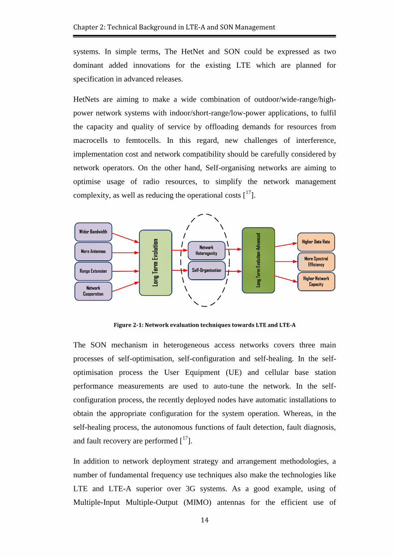
]. Furthermore, the proposed
techniques for LTE developments mostly focus on transmission enhancements
such as MIMO, CoMP, Range Extension, Resource Aggregation, etc., while the
LTE-A innovations are mostly focused on heterogeneity and self-organisation
attributes (see Figure 2-1), thanks to its compatibility with the existing LTE
Page 37
Chapter 2: Technical Background in LTE-A and SON Management
14
systems. In simple terms, The HetNet and SON could be expressed as two
dominant added innovations for the existing LTE which are planned for
specification in advanced releases.
HetNets are aiming to make a wide combination of outdoor/wide-range/high-
power network systems with indoor/short-range/low-power applications, to fulfil
the capacity and quality of service by offloading demands for resources from
macrocells to femtocells. In this regard, new challenges of interference,
implementation cost and network compatibility should be carefully considered by
network operators. On the other hand, Self-organising networks are aiming to
optimise usage of radio resources, to simplify the network management
complexity, as well as reducing the operational costs [17
].
Figure 2-1: Network evaluation techniques towards LTE and LTE-A
The SON mechanism in heterogeneous access networks covers three main
processes of self-optimisation, self-configuration and self-healing. In the self-
optimisation process the User Equipment (UE) and cellular base station
performance measurements are used to auto-tune the network. In the self-
configuration process, the recently deployed nodes have automatic installations to
obtain the appropriate configuration for the system operation. Whereas, in the
self-healing process, the autonomous functions of fault detection, fault diagnosis,
and fault recovery are performed [17
].
In addition to network deployment strategy and arrangement methodologies, a
number of fundamental frequency use techniques also make the technologies like
LTE and LTE-A superior over 3G systems. As a good example, using of
Multiple-Input Multiple-Output (MIMO) antennas for the efficient use of
Page 38
Chapter 2: Technical Background in LTE-A and SON Management
15
orthogonal Frequency Division Multiple Access (OFDMA) in both downlink and
uplink transmissions is considered in 4G systems [18
]. Nevertheless, since the
concepts of multi-layer/tier deployment and self-organisation solutions are
proposed during the advanced releases of LTE networks, these aspects need more
investigations and comprehensive research to fully understand the implications of
their deployment.
This chapter presents the technical background in heterogeneous and self-
organising networks, as well as the challenges in multi-tier network deployments
for LTE and LTE-Advanced systems. The modulation schemes, deployment
methods and air interface descriptions are reviewed to identify network
compatibility with existing LTE systems. Furthermore, existing access control and
access modes are also described prior to the technical descriptions of resource
allocation, mobility management and interference mitigation. This chapter aims to
explain these background LTE technologies before presenting the novel
contributions of this research. By presenting this background knowledge on LTE,
at the same time as system level information on self-organising networks, an
insight can be obtained for inventing novel solutions to the challenge of deploying
femtocells in LTE networks. At the end, a brief chapter summary summarises the
contents and issues presented in this chapter.
2.2. Fundamental Network Construction and LTE-Advanced Characteristics
As a true 4G cellular network, LTE-A and its proposed self-organisation should
fulfil the network necessities to reach the target pick data rate and scalable system
bandwidth. The additional functionalities are only applicable on the system, if
there is a reliable network platform available from previous releases and network
planning.
2.2.1. Existing LTE Characteristics and Compatibility
The conventional cellular network deployment is typically launched based on
homogeneous architecture by applying a macro-centric planning process, in which
the base stations are operating within a planned layout and serving the user
terminals. The values of receiver noise floor, transmit power levels and antenna
radiation patterns are similar for all the base stations in homogeneous networks.
Page 39
Chapter 2: Technical Background in LTE-A and SON Management
16
Furthermore, all the base stations in homogenous networks prepare similar
backhaul connectivity to the data network and unrestricted access to the user
terminals in the network, while serving roughly the same number of users [6].
Therefore the additional carriers are required to overcome the capacity
shortcomings when the traffic demands are growing. Nevertheless, as a main
target of 3GPP LTE-A systems to improve the ITU requirements, the new releases
of LTE-A systems are compatible to and share the frequency bands with the first
LTE release.
2.2.2. Network Heterogeneity and Heterogeneous Architecture
Throughout this network heterogeneity investigation, two types of base stations
are being considered within different HetNet architectures. One is the long-range
macrocell base station, called as evolved Node-B (eNB), and the other is one or
more short-range nodes, which in case of femtocell nodes are called Home
evolved Node-B (HeNB). As a technical consideration, these two sub-networks
could be assumed to contain two cooperating network layers, or tiers, which are
linked through the core system [4]. By providing the indoor area coverage devices
like femtocells, this will support a variety of services by using these low power
access points, which can provide the higher data rate of several Mbps for the
indoor areas [19,20
].
The successful co-existence of both macro and femto nodes in an LTE network
requires considered research for obtaining efficient and elegant solutions. Since
the radio resource management protocols for coexisting macro and femto nodes
are not specified by the standards (e.g. 3GPP’s UMTS LTE) [4], a solution could
be found by applying network organisation and cognition schemes into the
existing systems.
2.2.3. Base Station Application and Deployment
Small-cell concept is referred to networks with smaller size of implementation,
shorter communication range, lower transmission power and lower deployment
costs. To provide network users with the experience of a ubiquitous network with
improved QoS at both the cell-centre and the cell-edge areas, a heterogeneous
network solution should propose cooperative spectral efficiency algorithms by
Page 40
Chapter 2: Technical Background in LTE-A and SON Management
17
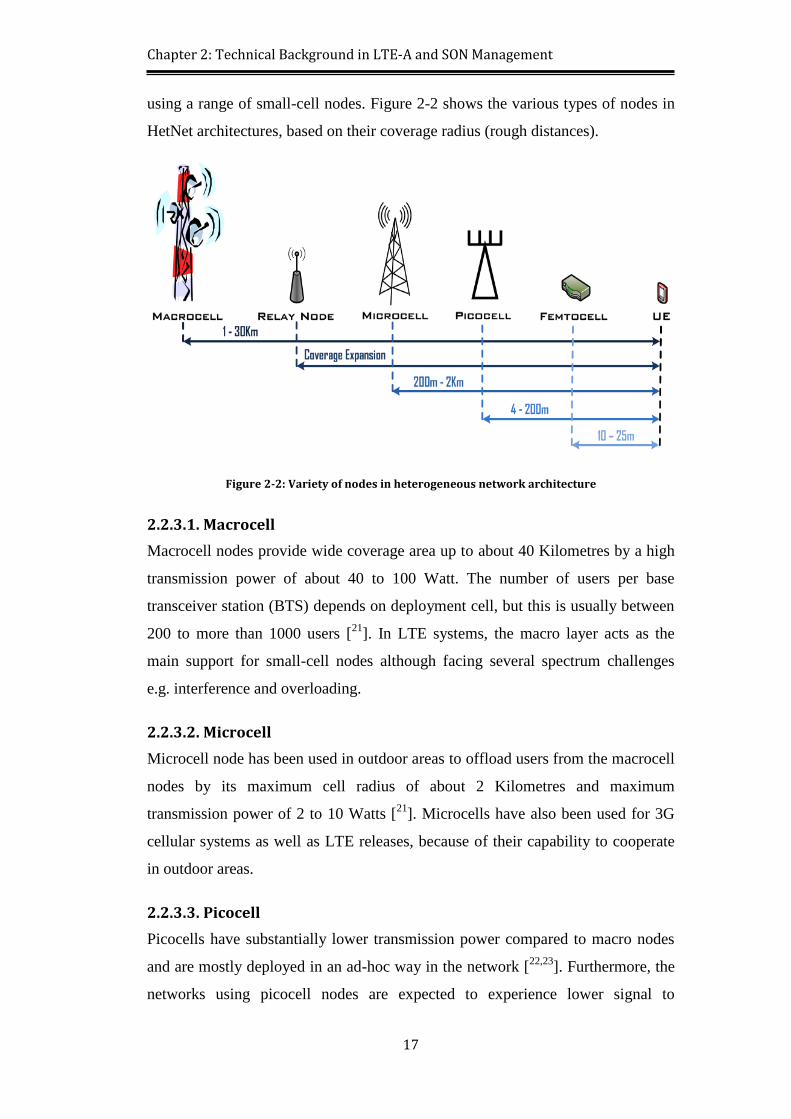
using a range of small-cell nodes. Figure 2-2 shows the various types of nodes in
HetNet architectures, based on their coverage radius (rough distances).
Figure 2-2: Variety of nodes in heterogeneous network architecture
2.2.3.1. Macrocell
Macrocell nodes provide wide coverage area up to about 40 Kilometres by a high
transmission power of about 40 to 100 Watt. The number of users per base
transceiver station (BTS) depends on deployment cell, but this is usually between
200 to more than 1000 users [21
]. In LTE systems, the macro layer acts as the
main support for small-cell nodes although facing several spectrum challenges
e.g. interference and overloading.
2.2.3.2. Microcell
Microcell node has been used in outdoor areas to offload users from the macrocell
nodes by its maximum cell radius of about 2 Kilometres and maximum
transmission power of 2 to 10 Watts [21
]. Microcells have also been used for 3G
cellular systems as well as LTE releases, because of their capability to cooperate
in outdoor areas.
2.2.3.3. Picocell
Picocells have substantially lower transmission power compared to macro nodes
and are mostly deployed in an ad-hoc way in the network [22,23
]. Furthermore, the
networks using picocell nodes are expected to experience lower signal to
Page 41
Chapter 2: Technical Background in LTE-A and SON Management
18
interference ratio, because of their unplanned deployment on the network, which
results in a challenging RF channel for control channel transmissions to the cell-
edge users. An important point regarding macro-pico deployment is the large
difference of the transmit power between macro and pico nodes in the network,
which causes the smaller downlink coverage of a picocell compared to the macro.
However, this is not the same case for uplink, which uses the same transmit power
strength from user terminal to all the base stations, because this only depends on
the user terminal’s transmit power [6]. Picocell transceivers could be used either in
indoor or outdoor areas, but their coverage radius is up to 200 meters only, which
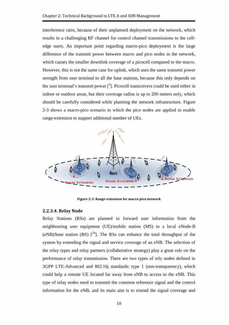
should be carefully considered while planning the network infrastructure. Figure
2-3 shows a macro-pico scenario in which the pico nodes are applied to enable
range-extension to support additional number of UEs.
Figure 2-3: Range-extension for macro-pico network
2.2.3.4. Relay Node
Relay Stations (RSs) are planned to forward user information from the
neighbouring user equipment (UE)/mobile station (MS) to a local eNode-B
(eNB)/base station (BS) [24
]. The RSs can enhance the total throughput of the
system by extending the signal and service coverage of an eNB. The selection of
the relay types and relay partners (collaborative strategy) play a great role on the
performance of relay transmission. There are two types of rely nodes defined in
3GPP LTE-Advanced and 802.16j standards: type 1 (non-transparency), which
could help a remote UE located far away from eNB to access to the eNB. This
type of relay nodes need to transmit the common reference signal and the control
information for the eNB, and its main aim is to extend the signal coverage and
Page 42
Chapter 2: Technical Background in LTE-A and SON Management
19
services. On the other hand, type 2 (transparency) could help a local UE, which is
located within the coverage of eNB and has a direct communication link with
eNB to improve the link capacity and service quality. So it does not transmit the
common reference signal and the control information and its main aim is just to
increase the overall system capacity, by achieving the transmission gain and
multipath diversity for the local UEs [25
]. Therefore, the general application of
relay nodes in combination with macrocell is to pass transmission for out of range
mobile nodes, as well as improving the existing connections.
2.2.3.5. Femtocell
Femtocell is introduced as an intelligent access point to support 3G and 4G
mobile devices, which use cellular air interface, e.g. CDMA2000, UMTS, LTE
and LTE-A. Femto nodes are tightly integrated with the existing macro networks,
and so their use and switching between macro and femto are seamless for the
users in particular. The femtocell network architecture and its specifications allow
the ordinary users to install them with plug-and-play simplicity [26
]. In case of
using of femtocell within closed mode HetNet architecture, only the registered
subscribers of femtocell are allowed to access. Hence, the nearby users, either
from the neighbouring femto, or general macro node are likely to face severe
interference caused by the femtocell [6]. Therefore, when deploying femto sub-
network, which is an indoor application, there is a need to consider an appropriate
control strategy to receive the maximum support from this cooperation.
There is an additional focus on femtocell in HetNet architecture, compared to the
other small-cells, because of its low-power, low-complexity and compatibility
with the existing core network mobile network operators (MNOs), while
promoting different ranges of tariffs for home broadband.
2.3. Conventional LTE Network Multiplexing and Duplexes
LTE data transmission is mostly based on orthogonal frequency-division
multiplexing (OFDM) to carry the data on multiple carrier frequencies. In this
regards, the available bandwidth is divided into multiple overlapping sub-carriers.
The OFDM sub-carriers are orthogonal to each other, so the inter-symbol
interference is prevented by applying independent modulation for each subcarrier.
Page 43
Chapter 2: Technical Background in LTE-A and SON Management
20
2.3.1. Supported Duplexes
In mobile systems duplex communication is the ability of the users to establish a
dual-way communication for transmission and reception, rather than a simplex
communication, which has only-transmit or only-listen modes of operation. Two
types of duplexes are defined in LTE, namely: LTE time division duplex (LTE
TDD) and LTE frequency division duplex (LTE FDD).
2.3.1.1. LTE TDD
The same frequency band is used for duplex in LTE TDD in both the directions,
which is also called as “unpaired spectrum”. The same frequency channel hosts
transmit and receive processes in different time-slots in asymmetric turns.
Therefore, the number of time-slots in downlink is higher than the number of
time-slots in uplink [27
].
2.3.1.2. LTE FDD
In LTE FDD, the radio transmitter and receiver operate in different carrier
frequencies at the same time. The uplink and downlink frequency bands are
separated by the frequency offset, which prevents latency, although needing more
complex circuits and deployment.
2.3.2. LTE Frame Structure
The system robustness is improved by splitting the transmission data between
multiple carriers. The LTE frame structure based of OFDM slots and FDD duplex
is shown on Figure 2-4. The typical LTE frame has the overall length of 10ms,
which is divided into 10 subframes and 20 individual slots. The length of each slot
in the radio frame is 0.5ms and two slots make one LTE subframe of 1ms. Each
slot also contains 7 OFDM symbols including normal (short) cyclic prefix with a
copy at the end of the symbol. The most important function of cyclic prefix is to
perform as a guard interval to prevent the inter-symbol interference between the
symbols. If to involve the frequency domain into our structure, each of the OFDM
symbols includes 12 subcarriers, which altogether form one physical resource
block (PRB) as the most important unit in LTE in different measurements.
Therefore, we can say one two-dimensional unit in LTE is one PRB, which is
made of one slot in time domain and 12 subcarriers in frequency domain. Another
Page 44
Chapter 2: Technical Background in LTE-A and SON Management
21
two-dimensional unit in LTE is one Resource Element, which is made of one
symbol in time domain and one subcarrier in frequency domain.
Figure 2-4: LTE frame format with OFDM
2.3.3. OFDMA in Downlink
LTE downlink uses orthogonal frequency division multiple access, which
provides OFDM-based multiplexing for multiple access. OFDMA provides low-
data rate transmission and lower maximum transmission power from multiple
users. This also further improves the existing OFDM robustness, fading and
interference avoidance. Figure 2-5 shows the subcarriers in OFDMA multiplex.
Figure 2-5: Multiple subcarriers configuration in OFDMA
Page 45
Chapter 2: Technical Background in LTE-A and SON Management
22
The deployment flexibility across different frequencies needs minimum
modification by using orthogonal frequencies in OFDMA. Scalability of
OFDMA is one of the most important advantages, in which its subcarrier structure
makes it able to support a wide range of bandwidth. The scalability of this
multiplexing method also provides more flexibility of deployment with minimum
modification to the existing air interface. This system is able to be deployed in
different frequency band intervals to address the different spectrum allocation
techniques. In the case of transmission methods, since the processing of OFDMA
signal provides effectively frequency flat channels, full multi-input-multi-output
(MIMO) technology could be deployed in combination with existing OFDMA
system [28
], which could be highly used in later versions of LTE-Advanced.
2.3.4. SC-FDMA in Uplink
In LTE-A uplink, single carrier frequency division multiple access (SC-FDMA) is
preferred over OFDMA, because it reduces the peak to average power ratio
(PAPR). The SC-FDMA process has similar structure to OFDM and OFDMA,
except the addition of a discrete Fourier transform (DFT) block before mapping
the subcarriers. Therefore, SC-FDMA could also be considered as an OFDMA
modulation, but with an extra DFT block. SC-FDMA is more attractive compared
to OFDMA, since it reduces the PAPR by a ratio of the dimensions of the inverse
DFT (IDFT) and DFT in its modulator, which reduce cost of power amplifier for
mobile users. Figure 2-6 [29
] depicts the symbol transmissions for OFDMA and
SC-FDMA [30
].
Figure 2-6: OFDMA vs SC-FDMA transmissions [29]
Page 46
Chapter 2: Technical Background in LTE-A and SON Management
23
2.4. Necessity of Self-Organising Approaches for HetNet
Latest releases of LTE-A systems, which are more focused on heterogeneous
networks, plans to fulfil coverage and capacity requirements. Relation of the
advanced versions of LTE with heterogeneity from one side, and self-
configuration plans in each step of LTE-Advanced form the other side, could form
a heuristic process in this regard. Figure 2-7 shows the self-organisation process
in cellular networks.
Figure 2-7: Self-organisation process in cellular networks
2.4.1. SON Solution for Resource Allocation
The LTE base stations are expected to be equipped with SON capabilities to
reduce human involvement, as well as saving capital expenditures (CAPEX) and
operational expenditures (OPEX) [31
]. Considering the exponential growth of data
traffic, channel optimisation is the main objective of resource allocation strategies
in LTE-A systems. Therefore, strategies like fractional frequency reuse, partial
reuse and channel sharing are planned along with SON algorithms for network
cooperation, e.g. macro-femto cooperation, in case of frequency re-use schemes.
2.4.2. SON Solution for Mobility Management
Unnecessary handovers are known as the critical challenge in network mobility
management, which are technically caused by inaccurate network measurements.
Furthermore to plan a ubiquitous network support, it is necessary to avoid any
needless handover, e.g. unnecessary macro to femto handovers. Self-Organising
Page 47
Chapter 2: Technical Background in LTE-A and SON Management
24
mobility management algorithms initiate a comprehensive handover process with
more accurate network condition monitoring to maximise network reception and
minimise the number of unnecessary handovers within the cells.
2.4.3. SON Solution for Interference Coordination
The network cooperation is introduced to reduce the total costs for the network
operators. The inter-cell interference management has significance in concept of
HetNets, because of the importance of interference as one of the major challenges
in OFDMA-based networks [13
]. In downlink side of network, where the network
nodes transmit to a variety of users, more challenges are expected to be faced due
to higher interference. Transmission power is also important to control in order to
manage the interference in the neighbouring cell, as well as the target cell.
Therefore, it seems very logical as a common practice for LTE, to use less
transmit power near the cell border in order to apply interference mitigation
measures and reduce the inter-cell interference [13
].
2.5. Deployment Structure and Interfaces
As an OFDM-based technology, LTE technology is prioritised over the
conventional 3G releases by its physical characteristics. The mentioned OFDMA
and SC-FDMA transmissions are accompanied by channel optimisation
techniques, like co-channel deployment, to obtain positive effects on QoS
satisfaction for the end users. Furthermore, supported modulation schemes and
interface architecture are also prominent characteristics of LTE network, which
could bring network capacity enhancements.
2.5.1. Deployment Methodologies
In small-cell deployment, macro-femto cooperation requires specific network
design to deploy a dual-way transmission by use of bandwidth resources. The
deployment methodology of macro and femto sub-networks specifies channel
allocation and resource blocks transmissions, either by sharing the frequency
channels or by allocating separate channels.
2.5.1.1. Multi-Channel Deployment
In multi-channel deployment, macro and femto nodes use separate frequency
channels for transmission. In this deployment, single or multiple frequency bands
Page 48
Chapter 2: Technical Background in LTE-A and SON Management
25
are allocated to each application, which could avoid co-channel interference
because of using different frequency channels. Preventing interference by using
separate channels could raise quality of service by decreasing number of dropped
packets in the network layer and increasing the number of successful
transmissions. However on the other hand, the multi-channel deployment strategy
could not fulfil the channel optimisation and financial expectations.
2.5.1.2. Co-Channel Deployment
Use of same frequency channels for outdoor and indoor applications is preferred
in LTE-Advanced. The co-channel deployment capabilities of heterogeneous
networks provide the advantage of channel optimisation, which reduces the
network implementation costs by saving more frequency channels. Nevertheless,
a heuristic macro-femto cooperation strategy is required for this type of
deployment, not only to avoid the co-channel interference, but also to manage
other network layer responsibilities among the sub-networks, e.g. handover and
resource managements.
2.5.2. Modulation Schemes
The quadrature amplitude modulation (QAM) is used to modulate the transmitted
bits within the OFDM signal in LTE shared channels. Applying different
modulation schemes in LTE makes the bit detection process more robust against
distortion and noise within the transmission channel. Three types of modulation
schemes are used as shown in Figure 2-8.
Figure 2-8: Modulation types in LTE
In case of having noisy channel conditions, the modulated data with quadrature
phase shift keying (QPSK) provides more reliable decision at the receiver side,
Page 49
Chapter 2: Technical Background in LTE-A and SON Management
26
because of a large distance between the modulation points (2 bits per symbol). On
the other hand, 16QAM and 64QAM map 4 and 6 bits onto one modulation
symbol respectively, which results higher data throughput when the SNR on the
transmission channel is higher.
2.5.3. Interface Architecture
The air interface of LTE network is called evolved universal terrestrial radio
access network (EUTRAN), which is interfaced to the evolved packet core (EPC)
configuration. The LTE interface architecture is depicted in Figure 2-9. The X2
interface provides inter-connections among macro nodes (eNodeBs). The entire
X2 interface is applicable for the nodes within a unified network, and not
individual networks like home or indoor applications.
Figure 2-9: Entire LTE interfaces architecture
The S1 interface is used to connect eNodeBs to the EPC platform through the
management and system architecture gateways. Therefore there is capability to
deploy S1 interface between small-cell nodes, e.g. femtocells (HeNodeBs), and
EPC through the appropriate gateways.
2.6. Channel Sharing and Access Control Necessity
The 3rd
generation partnership project (3GPP) Release 10 LTE-A [32
] has been
revealed with further enhancements to the LTE systems to fulfil IMT-Advanced
expectations. Heterogeneous networks, as a prominent improvement of LTE-A
Page 50
Chapter 2: Technical Background in LTE-A and SON Management
27
over LTE, requires channel use and access control to be considered to optimise
the bandwidth allocation among variety of the sub-networks.
2.6.1. Resource Allocation Scheme
The node selection in LTE Rel-8 is based on downlink received signal strength.
Considering the same strategy for LTE-A, the usefulness of low-power nodes will
be highly decreased. The reason is, because of higher power and larger coverage
of macrocell, they attract most of the user terminals, while not providing enough
resources to efficiently serve those users [6]. Therefore, the foremost consideration
of resource allocation is the fair distribution of channel resources, which is
necessary to balance the traffic and avoid QoS drops within the network.
2.6.2. Frequency Reuse Pattern
Frequency reuse strategy is widely used on the existing generations of cellular
networks, in which the transmission of different cells or sectors of a cell are
orthogonalised in the frequency domain by splitting the total available spectrum
into non-overlapping partitions [4]. The use of wide channels for LTE and LTE-A
networks limits the available spectrum, which results in performance and quality
reductions in each cell. Therefore, the application of enhanced techniques for
frequency reuse is necessary to begin the channel optimisation. Figure 2-10 shows
two different strategies for frequency reuse within neighbouring cells.
Figure 2-10: Different frequency reuse strategies
Although the frequency reuse pattern results in the saving of bandwidth resources,
applying the same frequency for the neighbouring cell sectors results in
Page 51
Chapter 2: Technical Background in LTE-A and SON Management
28
interference and network quality degradations, especially for the users at cell
boundaries.
2.6.3. Network Access Modes
It has been proven that the traffic offload to femtocells can decrease the costs for
the network operators by up to 70% [33
]. In this regard, network access is another
important sub-network function, e.g. for indoor nodes, which is required for
access by public users. Different network access modes are categorised based on
network permission to the users to be managed by the transceivers within each
geographic area.
2.6.3.1. Open Subcarrier Group
In open subcarrier group (OSG), also called as “Open Access” mode, the network
user groups have instant access to any part of the network upon demand. In
macro-femto network, both macro users and indoor users can use the femtocell,
while there is no such list of allowed users in femto access points.
2.6.3.2. Closed Subcarrier Group
On the other hand, there are some problems due to deployment of a larger number
of low-power nodes. Especially in co-channel deployment scenarios in
heterogeneous networks, interference may become serious due to use of low-
power nodes, which could lead to high outage of the macro users [9]. The
femtocell is able to work in a closed subcarrier group (CSG), also known as
“Closed Access” mode, in which a list of allowed users is provided for the
femtocell. In this mode, only the users available on that list, i.e. CSG user, are
allowed to access to the femtocell. Since the possibility of inter-cell interference
in CSG is more than OSG, appropriate interference coordination schemes are
necessary to be planned in network cooperation.
2.6.3.3. Hybrid Access Mode
Hybrid access mode is a new concept in addition to open and closed access
modes, which is proposed in LTE release 9. In hybrid access mode, all the users
have open access to the cell, but those users who are subscribed have priority to
get access and get charged differently [34
]. Therefore, the cell treats UEs as CSG if
Page 52
Chapter 2: Technical Background in LTE-A and SON Management
29
their ID is in the access list and gives them priorities, otherwise it treats them as
OSG and serves them as normal.
2.7. LTE-Advanced Technical Challenges
Deploying the existing LTE platform in the transition to advanced LTE systems
leads to challenges in various aspects such as network capacity, quality of service,
resource scheduling, handover planning, inter-cell interference coordination, etc.
A brief description and relevant suggestions are made in this section to become
more familiar with the main technical challenges when dealing with new releases
of heterogeneous LTE network. Figure 2-11 shows a typical HetNet scenario with
its technical challenges.
Figure 2-11: Technical challenges in a HetNet scenario
2.7.1. Capacity and Coverage Support
The average capacity of the network is defined as aggregated throughput from all
users connected to a single cell. Furthermore, the average cell coverage is also
defined as the lowest user throughput that can be guaranteed in 95% of cases [35
].
The capacity and coverage optimisation algorithms could guarantee acceptable
values for capacity and coverage by increasing the transmission power assigned to
a physical resource block (PRB), but also causes more inter-cell interference.
Therefore the proper ICIC technique is also needed to be considered along with
these algorithms [13
].
Page 53
Chapter 2: Technical Background in LTE-A and SON Management
30
2.7.2. Overall Quality of Service in HetNets
Although the network MIMO is applied in LTE-Advanced systems, it does not
suggest a guaranteed quality of service. There are some challenges related to
timing issues of the packets belonging to different streams in a diverse QoS
network. The first challenge is the use of MIMO to manage the packet
transmissions with diverse QoS characteristics, and the second challenge is
finding of appropriate radio resources for each stream to ensure QoS for different
MIMO topologies [36
]. Therefore, QoS satisfaction is required to be considered,
while applying coverage and capacity planning.
2.7.3. Channel Optimisation and Resource Allocation
The necessity of having a heuristic resource allocation plan is more dominant
when a variety of applications are deployed within HetNet architecture. The
resource partitioning could be deployed with different techniques, such as time-
domain, frequency-domain, or spatial-domain. The time-domain partitioning
could better adapt to user distribution and traffic load changes, while the
frequency-domain partitioning is less granular and flexible for resource allocation,
but is more feasible in asynchronous networks [6]. Hence, applying a self-
organising resource allocation could be more effective.
2.7.4. Mobility Management and Handover
Different issues need to be considered to obtain the maximum outcome in case of
users’ mobility. User speed, available bandwidth, macro and femto priorities,
power of the transmitted signal, etc. are essential to be considered to maximise the
network throughput. The unnecessary handovers also need to be minimised to get
to the utmost efficiency in case of users’ mobility.
2.7.5. Interference Challenge and Mitigation Plan
The interference mitigation scheme is generally categorised into three main
techniques of: interference cancellation, interference averaging and interference
avoidance techniques [14
]. Applying of the interference avoidance plan results
upgraded performance with less complexity within the network, comparing to the
interference cancellation and averaging schemes. Therefore the interference
avoidance technique is preferred to be applied within the entire network. The most
significant challenge in this regard is making a trade-off between channel
Page 54
Chapter 2: Technical Background in LTE-A and SON Management
31
optimisation and an interference-free network, which is planned to be addressed
by developing inter-cell interference coordination (ICIC) algorithms.
2.8. Summary
This chapter includes the background study in LTE-Advanced, heterogeneous and
self-organising networks. The existing LTE characteristics and compatibility are
discussed along with its new capabilities towards LTE-A. Using OFDMA in
downlink, SC-FDMA in uplink, and a wide range of small-cell nodes would
facilitate in the transition process towards LTE-Advanced generation. As further
requirements, the application of self-organising methodology by using of self-
configured algorithms among macrocell, femtocell and users, is proposed as the
main contribution of this research.
In next chapters, a cooperative LTE-A network containing macro and femto tiers
will be discussed, and a self-organising solution will be applied to deal with the
proposed network challenges. The SON algorithms will be presented, simulated
and analysed for resource allocation, mobility management and inter-cell
interference coordination to obtain the maximum network capabilities.
Page 55
Chapter 3: Multi-Layer Sub-Channel Allocation and Access Control
32
Chapter 3 Multi-Layer Sub-
Channel Allocation and Access
Control
Implementation of a multi-layer network with coordination of outdoor and indoor
applications requires a reliable channel allocation technique to fulfil the coverage
fairness, as well as QoS expectations. Since all the network users share limited
bandwidth and channel resources within the HetNet architecture, the channel
allocation technique needs to consider a number of impediments, e.g. channel
interference, to deliver the maximum efficiency to the end users. This chapter
proposes a cooperative macro-femto LTE-A system followed by a novel channel
allocation and access control technique to form a SON solution in case of channel
sharing among the mobile users. The high-demand applications are planned and
simulated through the intended network, in which the node and model statistics of
the system are evaluated and analysed to compare the network performance with
and without the suggested channel allocation technique.
3.1. Chapter Introduction
Femtocells are recently proposed as low-power, low-range and low-cost cellular
base stations to be used as indoor applications for domestic and enterprise uses.
The femtocell routers are directly connected to the backhaul network through the
internet protocol (IP) by using of regular connection links, e.g. optical fibre and
asymmetric digital subscriber line (ADSL) [37,38
]. Femtocell networks could also
cooperate with high-range base stations like macrocells to form a heterogeneous
architecture, as part of the advanced networking method in new releases of
cellular networks. In addition to the femtocell physical advantages, e.g. size,
power, etc., its network planning could also facilitate the network optimisation by
eliminating the existence of coverage holes, especially in cell boundaries. The
Page 56
Chapter 3: Multi-Layer Sub-Channel Allocation and Access Control
33
plug-and-play capability of the femtocell routers make the users able to subscribe
for this application and enhance their network coverage when they are located in
their home, school or office. In new releases of LTE systems, there has been more
focus to develop network heterogeneity in LTE-Advanced versions by using of
short-range and medium-range base stations like microcell, picocell and
femtocell. Following the first standardization in 2009, the 3rd
generation
partnership project (3GPP) has proposed its release 10 in March 2011. 3GPP Rel-
10 mostly focuses on independent SON function as an important functionality of
LTE new releases. The SON coordination in 3GPP strategy contains the two
aspects of (1) coordination among configuration management and configuration
changes by SON functions, and (2) coordination between different SON
functions, analysed on a case by case basis [39
].
The allowed bandwidths for component carriers in LTE are 1.4 MHz, 3.0 MHz,
5.0 MHz, 10.0 MHz, 15.0 MHz and 20.0 MHz. Table 3-1 shows the number of
Physical Resource Blocks (PRBs) for each channel bandwidth.
Table 3-1: Number of physical resource blocks in each LTE bandwidth
Furthermore, the technical title of LTE-Advanced belongs to the LTE new release
11, which continues the work on SON attributes and network heterogeneity,
aiming to develop improvements to the network capacity and data rate. The 3GPP
new releases also propose carrier aggregation which let the users to use a wider
bandwidth to increase their throughputs, by combining 5 LTE Rel-8 carriers of 20
MHz to form an aggregated bandwidth of up to 100 MHz (Figure 3-1).
Page 57
Chapter 3: Multi-Layer Sub-Channel Allocation and Access Control
34
Figure 3-1: Carrier aggregation process in LTE-A systems
The necessity of network heterogeneity and use of indoor applications within a
heterogeneous network are becoming more dominant, as network demands are
increasing [40,41
]. Moreover, the optimised use of available spectrum is also
becoming a challenge for network operators to make their financial aims
promising, while fulfilling network expectations. Since the self-organising
characteristics of the heterogeneous network systems are proposed as a main
feature of new releases in LTE-A, resource management planning should be
carefully considered to prevent the foreseen challenges in cooperation between
different types of base stations.
Figure 3-2: Hardware requirements for resource management in LTE-A
Page 58
Chapter 3: Multi-Layer Sub-Channel Allocation and Access Control
35
As is shown in Figure 3-2, the SON channel sharing management for macrocell
and femtocell contains a number of self-configured processes and units, e.g.
network elements management (NEM), policy and charging rules function
(PCRF), mobility management entity (MME), and macro/femto gateway [42
]. As
is shown in this figure, the physical gateways for each of the macro and femto
layers act as the main entrance to each network layer during the inter-connections.
The processes also contain internal communications in order to provide the
transmission decisions for different applications, based on their expected QoS.
This chapter proposes a macro-femto heterogeneous network on LTE-A platform,
followed by a novel sub-channel allocation for spectrum management in presence
of macrocell and femtocell base stations. The proposed technique is based on
SON algorithms for hybrid fractional frequency reuse (HFFR) method between
macrocell and femtocell users. The cell partitioning is designed as frequency reuse
scheme to allocate appropriate sub-channels to the cell-centre and cell-boundary
users of both macrocell and femtocell, while considering the network capacity and
quality expectations.
In the simulation and analysis sections, different LTE-A network scenarios are
conceived in OPNET modeler network simulator to simulate the application of the
proposed resource allocation algorithm in macro-femto networks, and detailed
analyses are made to compare different statistics of network, while presenting a
range of applications. The main contribution of this chapter is development of a
novel channel allocation technique with considering SON methodology as the
main solution for the network cooperation among macrocell and femtocell sub-
networks.
3.2. Related Work
Multiple features are needed to be considered as part of the LTE-A resource
management and spectrum allocation process. Presentation of the femtocell
capabilities, its arrangement as part of a multi-layer network in cooperation with
macrocell, and macro-femto resource allocation by conventional frequency reuse
schemes have been recently under research. An important development that
appears in LTE-Advanced is the improvement of spectral efficiency per unit area,
by using a mixture of macro, pico, femto and relay base stations through a
Page 59
Chapter 3: Multi-Layer Sub-Channel Allocation and Access Control
36
heterogeneous network (HetNet), which enables flexible and low-cost
deployments and provide broadband access for the users within the entire
network. The important task is management and control of the interference to
deliver the benefits of such networks [6]. In this regard the overlay and underlay
strategies are being applied, in which the overlay method relates to the
exploitation and use of the resource units, which are not utilised by the spectrum
licence holders, called as spectrum white holes, and the underlay method
represents the use of the spectrum grey holes, which means the sharing of same
resources between primary and secondary users- in the transmission band [4].
The hybrid division cooperative transmission (HDCT) is introduced in research
[43
], which results in enhancement of throughput within femtocell systems. This
scheme applies a cooperative transmission (CT) to the users at the edge of the
femtocells base stations, whereas the conventional method is applied to the users
elsewhere. Applying CT to a user makes it capable to receiving the desired signal
from the serving femto base station, as well as from an adjacent femto base
station. Therefore the signal to interference plus noise ratio (SINR) of the user
would be improved by the two time synchronisation signals from adjacent femto
base stations. This performance is evaluated in both the terms of call blocking
probability and outage probability.
In research [44
], heterogeneous networks are discussed based on random applying
of femtocells on a macro network. The femtocells are planned to work as closed
cells to evaluate the effects of dominant interference in proximity of the closed
cells. The power control of HeNodeBs and using of advanced UEs with capability
of operation at low geometries are suggested to mitigate the interference.
However in research [45
], the authors suggest an advanced solution for macro-
femto challenges, by proposing of self-organisation for enterprise femtocells. The
investigated SON method is to automatically tune multiple parameters, such as
pilot power, resource blocks, radio spectrum and access control, at the cost of
complexity in network calculations.
The coexistence of LTE femtocells with the conventional GSM cellular networks
is also described in [46
]. The performance of the system is evaluated
mathematically based on the average SINR. The numerical results confirm that
Page 60
Chapter 3: Multi-Layer Sub-Channel Allocation and Access Control
37
the availability of the spectrum in such systems depends on the number and the
position of the femtocells in each GSM cell.
The authors in research [47
] present a spectrum sharing scheme in advanced
versions of the LTE system by using of cognitive methodologies. They believe
that one of the solutions to the spectrum scarcity in LTE-Advanced system is to
use the spectrum of digital video broadcasting (DVB) system by adopting
spectrum sensing and sharing methods. However the biggest challenge in this
solution is the trade-off problem between complexity and detection probability in
spectrum sensing schemes. To overcome the challenges, the research proposes a
cognitive-based spectrum sharing scheme, including auto-correlation based
advanced energy (ACAE) spectrum sensing, as well as spectrum sharing
procedure for sharing the spectrum between DVB and LTE-Advanced systems.
The Suggested ACAE spectrum sensing method is based on DVB OFDM symbol
calculation and decision making, which has lower complexity and higher
accuracy. The spectrum sharing part of this strategy, which comes after the
spectrum sensing scheme, is evolved and compared with the traditional spectrum
sharing methods. Most of the traditional spectrum sharing schemes do not
consider the neighbouring cells, which are not allowed to utilise the same
frequency simultaneously in mobile communications system. Therefore, for those
traditional systems, the spectrum efficiency of spectrum sharing schemes is not
very successful. To resolve this problem on the proposed spectrum sharing
scheme, the LTE-Advanced cells are separated into three groups based on
frequency reuse method (assuming the frequency reuse factor is 3). The spectrum
sharing procedure in this work includes spectrum decision, spectrum sharing,
spectrum releasing and spectrum mobility. The proposed cognitive based
spectrum sharing scheme for LTE-Advanced cells could reach higher performance
–by using of ACAE spectrum sensing scheme– as well as better spectrum
efficiency and fairness –by the spectrum sharing scheme– in its methodology.
To ease the channel availability variation in LTE-Advanced networks, it has been
discussed in research [36
] that the multiple-input-multiple-output (MIMO)
technology could be applied, as well as proposing the statistical traffic control
scheme, that comprise the packet transmission scheduling and the admission
Page 61
Chapter 3: Multi-Layer Sub-Channel Allocation and Access Control
38
control for LTE-Advanced. The result of these applications will be promising a
successful coexistence with wireless local area network (WLAN) in Industrial,
Scientific and Medical (ISM) radio band. The network MIMO in this work
includes a combination of both coordinated multi-point (CoMP) transmissions
from multiple LTE-Advanced base stations (eNBs) to one user equipment (UE),
and the cooperative relaying by applying multiple relay nodes (RNs) to forward
the packet to the UE.
Spectrum aggregation method is also presented in [48
], which could be used for
dynamic spectrum access cases, by an admission control algorithm and a spectrum
assignment strategy taking into consideration both the spectrum aggregation, as
well as the channel switch based on the state statistics of each channel. Based on
this research, the process of the spectrum aggregation generally contains the
following aspects:
(1) Designing of the guard bandwidth between carriers. Reducing the guard
bandwidth between the carriers improves the spectrum utilization efficiency.
(2) Selecting of the carrier bandwidths. The parameter called “Bandwidth Factor”
indicates the multiple relationships between the bandwidth of the aggregated
carriers of LTE. As an example, when the bandwidth factor is 2, one carrier
bandwidth is twice as large as the other one. Defining the bandwidth factor could
restrict the aggregation methods, but it reduces the complexity of transceivers.
(3) Aggregating of data stream. In this process, each carrier corresponds to an
independent data stream. The data stream aggregation scheme could be applied
either in MAC or physical layers, but the MAC layer is preferable for the
development of spectrum aggregation technology.
(4) Designing of control channels. There are also two alternatives in this case. The
first strategy will be based on the controlling process of one channel to the others,
and the second strategy is the controlling process of each channel on its data.
Comparing these two methods, the second method is preferred, in both cases of
power dissipation and costs.
Page 62
Chapter 3: Multi-Layer Sub-Channel Allocation and Access Control
39
Furthermore, the frequency reuse scheme for OFDMA-based cellular networks
resource allocation has been also proposed through the modulation and coding
scheme (MCS), resource block (RB) and transmission power (TP), which are
independently and dynamically allocated by each cell [31
]. As the result, the total
downlink transmit power is minimised, while satisfying the users’ throughput
demands. Furthermore in this method, each cell informs its neighbouring cell
about its cell-edge users’ allocated RBs, so preventing the other cells to target the
same RBs for allocation. The proposed power control scheme is shown to
improve 20% on throughput.
The relevant researches in literature review exploit a number of techniques for
resource allocation in heterogeneous networks, aiming to plan an interference free
network in early stages. The main aim of the existing resource allocation
techniques is to use either the power control strategy or the random PRB selection
for resource allocation, while fairness in bandwidth splitting among the users is
less exploited. Furthermore, the existing techniques mostly focus on interference
avoidance in the system, with fewer considerations about network complexity
when applying their channel allocation process. This chapter aims to initially
propose unique simulation scenarios for macro-femto network architecture
including additional network-level hardware, and will be followed by proposing a
novel self-organising resource allocation technique to obtain the improved
channel optimisation.
3.3. Problem Statement
The proposing of femtocell base stations within a heterogeneous architecture is
considered as a fundamental solution to the shortage of network capacity for
mobile users [49,50
]. The main application of femtocells could be expressed as
offloading part of user congestion from the general macrocell base stations, by
establishing short-range network spots within the entire network. However,
obtaining such a ubiquitous network needs an effective plan for a consistent
cooperation between the main macrocell application –defined as the first network
tier– and the additional femtocell application –defined as the second network tier–
by employing self-configuration techniques. It is very obvious for such a
heterogeneous macro-femto network that the available spectrum should be fairly
Page 63
Chapter 3: Multi-Layer Sub-Channel Allocation and Access Control
40
shared between the two network layers, to optimise the available spectrum
channels, while simultaneously considering the network capacity issues. This fact
shows the necessity of having an intelligent resource management which is able to
allocate resources at the right time to the right users. Therefore, the expected
challenge for LTE-A macro-femto network is to provide a cooperative resource
management, channel allocation and access control for both the groups of
macrocell and femtocell users, as is shown in Figure 3-3.
Figure 3-3: Cooperative resource management for a two-tier network
The proposed solution to the above mentioned problem is using of self-organising
network (SON) technique to make a network-layer link among the two network
tiers. In this solution, S1 and X2 interfaces are used as the links between
macrocell stations, femtocell stations, serving gateways and management entities
to establish the frequency reuse scheme in cell-edge and cell boundary areas. The
co-tier and cross-tier interference avoidance are also considered in this technique
while the sub-band allocations are planned in channel allocation. The proposed
SON technique has also significant effects in network throughput and delay, as is
confirmed by OPNET simulation results, compared to the macro-only network
and the existing traditional spectrum management techniques.
3.4. System Model
In homogeneous networks, only a network of macrocells (MeNodeBs) serves the
mobile users in each cell. In such networks, the MeNodeBs have similar
characteristics, e.g. antenna pattern, transmission power, modulation, access
method, etc. The cell splitting seems to be an applicable approach to solve the
Page 64
Chapter 3: Multi-Layer Sub-Channel Allocation and Access Control
41
capacity problems in LTE networks, by allocation of more base stations in the
cells. However this approach is not economically feasible in dense urban areas to
deploy more number of MeNodeBs within the network. Therefore deploying a
two-tier HetNet seems to be an appropriate solution in a cost-effective way for
both the network operator and users. The two-tier network contains the macro
nodes as the first tier, overlaid with the low-power/low-complexity nodes in the
second tier [51
].
In this part, the functions of the proposed SON resource management algorithm in
macro-femto LTE-A networks are discussed. The application of the proposed
resource management technique is to share the available spectrum band among
both the macrocell and femtocell layers in a two-tier LTE-A network. In this
regard, the additional femtocell sub-network (layer) is added into the existing LTE
macro sub-network, followed by the proposed modification in node model of
home evolved node-B (HeNodeB) in the network.
3.4.1. Channel Division
In this model, the initial resource channel of the system is divided into two main
resource sections, called as “Macro Sub-Channel” and “Femto Sub-Channel” to
support macrocell and femtocell users respectively. Each of the network sub-
channels includes a number of component carriers (CCs) which are positioned
into the spectrum band, as is shown in Figure 3-4.
Figure 3-4: Sub-channel allocation for LTE-A macrocells and femtocells
Page 65
Chapter 3: Multi-Layer Sub-Channel Allocation and Access Control
42
To remove the coverage holes in homogeneous networks, picocells are generally
used with a coverage area between 40-75 meters, and an omnidirectional antenna
with about 5dBi antenna gain provides indoor coverage to users in public places
e.g. schools, airports, etc. [52
]. However on the other hand, femtocells with 10-25
meters coverage and 10-100 mW power are used as access points (APs) in home
applications, which operate in licensed spectrum that is managed by mobile
operators. Femtocells connect to the cellular network via broadband
communication links, e.g. digital subscriber line (DSL) to enable fixed mobile
convergence (FMC) [53
].
3.4.2. Macrocell and Femtocell Air Interfaces
The macro-femto coordination architecture could be defined either within a
centralised coordination, or a distributed coordination [54
]. In centralised
coordination architecture, the channel quality information from different BSs is
gathered by a centralised controller. The controller could be part of the radio
network controller (RNC) entity in previous technologies like HSPA and UMTS.
However, in conventional LTE systems, due to the lack of RNC, this idea has not
been applicable.
On the other hand, in distributed coordination architecture, there is direct
coordination among the adjacent base stations to allocate appropriate resources to
the users, especially the cell edge users, as well as to mitigate inter-cell
interference. The coordination is established through the LTE interfaces X2 and
S1 in evolved universal terrestrial radio access network (E-UTRAN) platform [55
].
The LTE X2 interface is used to make a direct communication between different
eNodeBs to exchange signalling information when needed, while a full mesh is
not mandated within an E-UTRAN network. The X2 interface is mainly used to
exchange two types of information: load/interference-related information and
handover-related information. In addition to this, LTE S1 interface is widely used
for eNodeBs in SON networks to communicate with the mobility management
entity (MME) and serving gateway (S-GW) in the evolved packet core (EPC)
unit. Each of the X2 and S1 interfaces are split into two interfaces of control
plane, and user plane, which are based on stream control transmission protocol/IP
(SCTP/IP), and general packet radio service (GPRS) tunnelling and user datagram
Page 66
Chapter 3: Multi-Layer Sub-Channel Allocation and Access Control
43
protocols (GTP/UDP5/IP) stacks respectively [56
]. At the proposed internal
interfaces, as shown in Figure 3-5, the X2 interface is used to communicate with
the macrocell stations (eNodeBs), but obviously this X2 implementation is not
applicable to directly link the femtocell stations (HeNodeBs), because of their
diversity and personal indoor implementation.
Figure 3-5: Interfaces map for macro and femto tiers in LTE-A network
As a solution to link the fomtocells to the systems, the HeNodeB gateway (HeNB
GW) is proposed to be added into the system, as well as the existing MME/S-GW
units for the femto tier within EPC. Therefore, the S1 interface is used to initiate
communication between HeNBs and HeNB GW, as well as the MME/S-GW units
[57
]. LTE-A femtocells nodes use orthogonal frequency division multiple access
(OFDMA) air interface technology in cooperation with the existing eNodeBs
within the HetNets [51
].
Figure 3-6 shows the S1 interface set in macro-femto interfaces, including the
proposed gateways and units. The HeNB nodes communicate with EPC module
via S1-U and S1-MME interfaces, while the HeNodeB gateway and management
system entities and serving gateway are relaying the packets from and to the
femtocell stations.
Page 67
Chapter 3: Multi-Layer Sub-Channel Allocation and Access Control
44
Figure 3-6: The S1 interface set in macro-femto interfaces
3.4.3. Fractional Frequency Reuse
A frequency reuse scheme is introduced as an applicable solution in channel
optimisation, while also being the most effective solution in mitigating the effects
of interference. All the interference types in this regard happen only when the
aggressor node and victim node use the same frequency sub-channel [51
].
Therefore, the fractional frequency reuse (FFR) scheme is required for a planned
sub-channel allocation among macrocell and femtocell users.
In case of using the frequency reuse scheme for channel optimisation, the main
types of interference are categorised into two main categories. The first category
is when a femtocell station interferes with another femtocell user, because of
using the same sub-band, which is called “Co-Tier Interference”. The second
interference category is when a macrocell (or femtocell) station interferes with a
femtocell (or macrocell) user because of using the same sub-band, which is called
“Cross-Tier Interference”. Figure 3-7 shows the example scenarios of these
interference possibilities in frequency reuse. In practical assumptions, because of
considering macrocells as long-range base stations, the macro-to-macro co-tier
interference is avoided in practice, due to the long distances between the
macrocell base stations.
Page 68
Chapter 3: Multi-Layer Sub-Channel Allocation and Access Control
45
Figure 3-7: Co-tier vs. cross-tier interference in frequency reuse
3.4.3.1. Strict Fractional Frequency Reuse Scheme
To obtain better network optimisation, each cell is divided into two zones called
as centre-zone and edge-zone. In strict FFR, for a cluster of N cells, the frequency
reuse factor (FRF) of N is applied to edge-zone macro users (MUEs), while the
centre zone MUEs are allocated with a common frequency sub-band, i.e. the FRF
of 1. Therefore, the total of N+1 sub-bands are required to cover all the MUEs in
the cells. Although, the inter-cell co-tier interference is mitigated for eNodeBs in
strict FFR schemes, the cross-tier interference would be significant, especially
near the transition areas of the centre-zone and edge-zone [51
]. In addition to this,
the co-tier interference may become severe for HeNodeBs in edge zones, as is
shown in Figure 3-8.
Figure 3-8: Strict fractional frequency reuse scheme
Page 69
Chapter 3: Multi-Layer Sub-Channel Allocation and Access Control
46
3.4.3.2. Soft Fractional Frequency Reuse Scheme
The cell partitioning in soft FFR is similar to the strict FFR scheme. However in
soft FFR scheme the MUEs in the centre-zone are allowed to use the MUE sub-
bands of the cell-edge zone of the neighbouring cells. Also for the femtocells, the
FUEs in the centre zone are allowed to use the FUE sub-bands of cell-edge zone
of the neighbouring cells, if is not used by macros in the same cell-centre.
Therefore, the soft FFR scheme is more bandwidth efficient, i.e. has higher
spectrum efficiency, in compared to the strict FFR. As a result of having more
options in selecting the sub-bands by the nodes, the co-tier interference would be
reduced for both macro and femto nodes.
However on the other hand, the cross-tier interference still needs to be mitigated
for users near the boundary of the centre and edge zones, as is shown in Figure
3-9. As the different colours show the different combinations of sub-bands for the
cell centres and also the cell edges (for macrocell), each of the cell-centre areas is
also allocated with a sub-channel from a different sub-band compared to the
neighbouring cells, which aims to reduce the drops in QoS by reducing the
possibility of co-tier interference with the neighbouring cells.
Figure 3-9: Soft fractional frequency reuse scheme
Figure 3-10 shows the sub-channel allocation for the cells 1, 2 and 3, using the
power (p) versus frequency (f). It can be observed in this figure, for example in
the hexagonal cell 1, both the macrocell in the cell centre and femtocell in the cell
Page 70
Chapter 3: Multi-Layer Sub-Channel Allocation and Access Control
47
edge use F1 and F3 sub-bands, which could result in cross-tier interference,
especially in the centre-border transition area. Therefore, it is also required for the
sub-channel allocations, even in soft frequency reuse, to consider the cross-tier
interference, as well as co-tier interference.
Figure 3-10: Sub-channel allocation function in soft frequency reuse
3.4.3.3. Hybrid Fractional Frequency Reuse (HFFR) Scheme
As is previously discussed in soft FFR scheme, the co-tier interference is reduced
due to the dynamic sub-channel allocation, but on the other hand, the cross-tier
interference still remains and requires mitigation. Therefore, the hybrid fractional
frequency reuse (HFFR) scheme is proposed, which consists of both co-channel
and orthogonal deployments for a two-tier network [58
].
Figure 3-11shows the orthogonal resource allocation for macrocell and femtocell
tiers in the proposed technique. At the first stage, the soft FFR is applied and the
cell-centre nodes are allocated with sub-channels from different sub-bands, as
well as the cell-edge nodes. In addition to this, the macrocell and femtocell tiers
(including the cell-centre and cell-edge users) are allocated with sub-bands in an
orthogonal way similar to OFDMA. Therefore, the cross-tier interference is also
mitigated when the macrocells and femtocells with the same sub-bands follow the
orthogonal allocations.
Page 71
Chapter 3: Multi-Layer Sub-Channel Allocation and Access Control
48
Figure 3-11: Resource allocation for macrocell and femtocell in HFFR
This approach comes from a similar idea in dealing with intra-frequency/intra-cell
interference, which is normally avoided inside the cells due to the orthogonality
between subcarriers in OFDMA. The quality of some reference signals received
by UE also plays a great role in resource allocation of LTE networks. These
reference signals in LTE are reference signal received power (RSRP) and
reference signal received quality (RSRQ) and each user is assigned part of the
spectrum based on these two signals. However RSRQ provides a more effective
metric for the complex optimisation of the reference signal, since it is based on
SINR [15,59
].
The area spectral efficiency (ASE) is used as a tool to determine the FFR
threshold distance under multiple parameters, e.g. cell loading, path loss, fading,
shadowing, etc. The main aim of using an appropriate frequency reuse scheme is
to attain an appropriate resource allocation, which totally results in obtaining
improved overall spectrum efficiency in the system. In a static resource allocation
for a fully loaded cell, the resource allocation is given as in Equation (3-1) [58
]:
𝑁 = 𝛥𝑁𝑂 + 𝑁𝐼 (3-1)
In which Δ denotes the reuse factor for fractional frequency reuse for a set of N
sub-channels (entire bandwidth), and NI and NO sub-bands allocated to the cell
centre and cell edge areas respectively. The ASE parameter is defined as the
achievable throughput per unit area per bandwidth in bits/sec/Hz/cell in the
network. Therefore, calculation of the total ASE in two-tier networks is important
to analyse the overall network throughput and network capacity. Considering the
Page 72
Chapter 3: Multi-Layer Sub-Channel Allocation and Access Control
49
high power cell edge areas with smaller resource allocation of 2
3𝑁𝑂 for our
calculations, the ASE for the home user femtocells is calculated as in Equation
(3-2) [58
].
𝐴𝑆𝐸𝑓𝑒𝑚𝑡𝑜 =2𝑁𝑂
3𝑁(𝜆𝑓
(𝐶𝐶)𝐶𝑓𝑒𝑚𝑡𝑜(𝐶𝐶)
+ 𝜆𝑓(𝐶𝐸)
𝐶𝑓𝑒𝑚𝑡𝑜(𝐶𝐸)
) (3-2)
The intensity of the femtocell base stations in inner cell and outer cell are defined
as in the two Equations below respectively:
𝜆𝑓(𝐶𝐶)
=𝑁𝑓𝐶𝐶
|𝐻1|
(3-3)
𝜆𝑓(𝐶𝐸)
=𝑁𝑓𝐶𝐸
|𝐻2|
(3-4)
Where the inner circle region of |𝐻1| = 𝜋R𝑡ℎ2 and the outer circle region of
|𝐻2| = 𝜋(R2 − R𝑡ℎ2 ) are defined for the inner radius or threshold distance Rth and
cell radius R. Furthermore, 𝐶𝑓𝑒𝑚𝑡𝑜(𝐶𝐶)
and 𝐶𝑓𝑒𝑚𝑡𝑜(𝐶𝐸)
are the average capacity of the
femtocell users located in the macrocell cell centre and cell edge areas
respectively.
On the other hand, the normalized area spectral efficiency for fractional frequency
reuse is defined as the average capacity per cluster cell over the cluster size times
the total channel times bandwidth. Assuming the three cluster cells with three cell
centres and three cell edges, the average ASE for macrocells FFR is given as in
Equation (3-5) [58
]:
𝐴𝑆𝐸𝐹𝐹𝑅 =3. 𝑁𝐼 . 𝐶𝐶𝐶 + 3. (
𝑁 − 𝑁𝐼
3 ) . 𝐶𝐶𝐸
3. 𝑁
(3-5)
Where the ergodic capacity for the fractional frequency reuse cell centre and cell
edge are calculated as in the two Equations below respectively:
𝐶𝐶𝐶 = log2(1 + 𝑆𝐼𝑁𝑅𝐶𝐶) (3-6)
𝐶𝐶𝐸 = log2(1 + 𝑆𝐼𝑁𝑅𝐶𝐸) (3-7)
Page 73
Chapter 3: Multi-Layer Sub-Channel Allocation and Access Control
50
In a multi-tier network with macrocells and femtocells, the total ASE for
femtocells inside a fractional frequency reuse macrocell is calculated as in
Equation (3-8):
𝐴𝑆𝐸 = 𝐴𝑆𝐸𝐹𝐹𝑅 + 𝐴𝑆𝐸𝑓𝑒𝑚𝑡𝑜 (3-8)
In which the average ASE for femtocell in our formulations is calculated based on
our assumption to consider the home user femtocells, as the second tier of the
network.
3.4.4. Sub-Channel Allocation Mechanism
The proposed SON resource allocation module is implemented in femtocell node
model in OPNET, as is shown in Figure 3-12. The node model includes media
access control (MAC), address resolution protocol (ARP), internet protocol (IP)
entities, e.g. TCP, UDP, RSVP, etc. and antenna modules.
Figure 3-12: Proposed resource management module in femtocell node model
Page 74
Chapter 3: Multi-Layer Sub-Channel Allocation and Access Control
51
The proposed resource management module is located between the MAC and
ARP modules in the HeNodeB node model, to transmit and receive packets
through its process model and apply management, scheduling and channel
allocation tasks as follows:
Spectrum Management: Obtain the channel information from MAC layer and
find out about the available resources;
Scheduling Decision: Make decision for the best available packet transmission
considering the frequency sharing issues;
Packet Forwarding: Forward the packets to the appropriate destinations in the
network layer;
The process flowchart of the self-organising scheduling decision system for
resource allocation is shown in Figure 3-13.
Figure 3-13: The self-organising resource allocation flowchart
Page 75
Chapter 3: Multi-Layer Sub-Channel Allocation and Access Control
52
The process is dependent on the sub-channel availability and network user
satisfactions to allocate the available sub-channels of the shared spectrum band.
The proposed model for resource allocation is implemented in OPNET network
simulator and described in later sections, based on application definition, user
identification and sub-channel allocation. Figure 3-14 shows the pseudo code for
the presented resource allocation algorithm. The process details and specifications
is defined later on and are based on different application configurations for the
macro-femto network. The SON resource allocation algorithm is inherently based
on fractional frequency reuse scheme, while considering the other required
transmission issues, such as the different types of applications, as well as the
users’ demand for each of the configured applications.
Figure 3-14: The proposed resource allocation process
The main aim of the proposed algorithm is to share the spectrum in an
interference-free network among macrocell and femtocell users, which is
approached by applying of this technique into the femtocell node model.
3.5. System Implementation
In this section the proposed resource allocation technique is implemented into the
system by creating a number of different simulation scenarios in OPNET modeler.
Page 76
Chapter 3: Multi-Layer Sub-Channel Allocation and Access Control
53
Firstly a brief introduction to OPNET modeler network simulator is made,
followed by the applied configurations and adjustments for each of the presented
scenarios.
3.5.1. Network Simulator Software
The proposed sub-channel allocation and access control technique is applied into
a two-tier LTE-Advanced platform with macrocell and femtocell applications. A
number of different scenarios in this regard are implemented in OPNET modeler
software version 17.5 (64-bit) to evaluate the network performance with and
without the proposed SON technique. OPNET modeler consists four functional
layers of: Network Layout, Node Model, Process Model and C++ Codes at the
inner layer for network function blocks and executives, as is shown in Figure
3-15. The new versions of modeler also support LTE network functionalities by
providing LTE node models and applications, such as file transfer protocol (FTP),
voice over internet protocol (VoIP), video conferencing, etc., as well as LTE
terrain configurations, e.g. propagation models, pathloss, fading, etc.
Figure 3-15: Simulation layers in OPNET modeler network simulator
Our network implementation is made by performing our algorithm development
in all the four simulation layers. Firstly the initial network layout is planned based
on the network specifications, such as the base station types, users’ trajectories,
communication links and terrain customization. As the second step, the required
node models are modified based on each project’s expectations and the proposed
algorithm. The modifications may include additional module insertion, while
Page 77
Chapter 3: Multi-Layer Sub-Channel Allocation and Access Control
54
carefully considering the open system interconnection (OSI) model for each node
model.
The process model also needs modifications by creating the required Enter and
Exit Executives and conditions according to the higher layers input and output
variables. The inner layer, which contains C++ codes are located in process model
executives, as well as model blocks, i.e. termination, diagnostic, function and
header blocks and also temporary and state variables.
3.5.2. Simulation Scenarios
The general simulation parameters are defined as in Table 3-2, which remains
constant in all the scenarios. All the users are defined with random movement
trajectories within their allocated cell areas, without exceeding their boundaries.
Table 3-2: General parameters in the simulation scenarios
Macrocell Parameter Simulation Value
Number of Cells 7
Macro Cell Radius 100 meters
eNodeB Max. Transmission Power 41 dBm
HeNodeB Max. Transmission Power 21 dBm
Carrier Bandwidth 20 MHz
Duplex FDD
LTE Frequency Band 1
Uplink Access SC-FDMA
Uplink Frequency 1920 MHz
Downlink Access OFDMA
Downlink Frequency 2110 MHz
Propagation Model HATA-small city
Pathloss Model Pedestrian-Urban Macrocell (3GPP)
Shadow Fading Urban Macrocell (3GPP)
MUE Mobility Random
MUE Speed 1 m/sec (3.6 Km/h)
Number of Tx and Rx Antennas 2×2
eNodeB Antenna Gain 15 dBi
Page 78
Chapter 3: Multi-Layer Sub-Channel Allocation and Access Control
55
In our simulation, a two-tier LTE-Advanced network is simulated in OPNET
modeler through three different scenarios. The preliminary LTE-A network
scenario contains seven hexagonal cells, six of which with one macrocell base
station, called as evolved NodeB (eNodeB), and six macro users, called as mobile
user equipment (MUE). The central hexagonal cell in this scenario exceptionally
covers eight MUEs to perform different applications. The femto tier will be later
added into the existing macro tier in next scenarios.
In the next scenarios the femto tier will be inserted into the system to cooperate
with the existing macro-only network. This network tier includes four femtocell
stations which are located in an indoor area, each of which supporting three
indoor users. The last scenario then applies the proposed sub-channel allocation
technique into the two-tier network to evaluate the network performance in
capacity and QoS.
3.5.2.1. Applications’ Specification
The following sections present the configured parameters and attributes for each
network application. Each application is defined with a common value called:
“Type of Service” or ToS. As an upgraded redefinition of ToS in wireless
communications, “Differentiated Services Code Point” or DSCP parameter is
being used as a simple mechanism to classify and manage the applications’ traffic,
as well as providing QoS expectations in the network. It provides low-latency in
the critical network applications, e.g. VoIP and video conferencing, as well as
providing best-effort service to the other applications, e.g. FTP and Email. Among
the different types of DSCP in OPNET, the applications in our simulation are
configured with expedited forwarding (EF) type of service, which presents low
loss and low transmission delay as the valuable advantages for real time
applications.
The value of “Traffic Mix” is also configured in the simulation to adjust the user
behaviour activities within the network, which form the traffic model. The
following descriptions illustrate the adjusted attributes for the expected QoS in
each of the simulated network applications:
Page 79
Chapter 3: Multi-Layer Sub-Channel Allocation and Access Control
56
VoIP Traffic Configuration: The voice over IP (VoIP) traffic is configured with
the GSM enhanced full rate (GSM EFR) encoder scheme, which is a speech codec
working with 12.2 kbit/sec data rate and provides a wire-like condition in
different background noise conditions. The DSCP type for the voice application is
configured to EF, as was explained earlier.
Application Parameter Configured Value
Voice Frames per Packet 1
Encoder Scheme GSM EFR
Differentiated Services Code Point (DSCP) Expedited Forwarding (EF)
Traffic Mix (%) All Discrete
Conversation Environment Land phone – Quiet room
FTP Traffic Configuration: The file transfer protocol (FTP) traffic in the
simulation scenarios is configured with the file size of 1.5 Mb per each
transmitted file. The percentage of download to upload in FTP is denoted by a
value called “Command Mix”. In this simulation, this value is adjusted to 100%,
which means that the application is configured to only perform the FTP
download. The “Inter-Request Time” value is only 1 second, means that the
application sends the next file download request only one second after finishing
the current file downloading.
Application Parameter Configured Value
Inter-Request Time (seconds) Constant (1)
Command Mix (Get/Total) 100%
File Size (bytes) Constant (1500000)
Differentiated Services Code Point (DSCP) Expedited Forwarding (EF)
Video Conferencing Traffic Configuration: The video pixel size of 128×240
pixels is defined for the simulated video application for frame inter-arrival time of
15 frames per second. The type of service in video conferencing application is
also defined by DSCP parameter, which is set to expedited forwarding.
Page 80
Chapter 3: Multi-Layer Sub-Channel Allocation and Access Control
57
Application Parameter Configured Value
Frame Size Info. (bytes) 128×240 pixels
Frame Inter-arrival Time Info. 15 frames/sec
Differentiated Services Code Point (DSCP) Expedited Forwarding (EF)
Traffic Mix (%) All Discrete
HTTP Traffic Configuration: The hypertext transfer protocol (HTTP) is the
communication protocol for World Wide Web. Hypertext is structured text that
uses logical links between nodes containing text. The HTTP page values are
configured as constant values, shown on the table, for the simulation scenarios.
Application Parameter Configured Value
HTTP Specification HTTP 1.1
Page Inter-arrival Time (seconds) constant (120)
Page Object Size constant (500)
Number of Objects (per page) constant (1)
Differentiated Services Code Point (DSCP) Expedited Forwarding (EF)
Email Traffic Configuration: There is a separate application type for email
traffic in OPNET modeler simulator. As shown in the table below, the application
inter-arrival times are configured as constant values and the email size is 1Mbytes
per email to be defined for the configured users.
Application Parameter Configured Value
Send Inter-arrival Time (seconds) constant (120)
Receive Inter-arrival Time (seconds) constant (120)
E-Mail Size (bytes) constant (1000)
Differentiated Services Code Point (DSCP) Expedited Forwarding (EF)
3.5.2.2. Macro-Only Scenario
The general and common parameters between all the scenarios are already
configured in Table 1 to be set for all our simulation scenarios. The first scenario
Page 81
Chapter 3: Multi-Layer Sub-Channel Allocation and Access Control
58
is to evaluate the overall network performance within a LTE-A network with
macrocell implementation. The network layout of the first scenario in OPNET
modeler is shown in Figure 3-16. The eNodeB in the centre hexagonal cell is
configured with a number of different applications for each macro user, as is
already described. There are a total of eight macro users (MUEs) in the centre
cell, of which three are configured with VoIP application, two users are
configured with a FTP application and each of the three remaining users are
configured with video conferencing, HTTP and email applications. It has been
decided to implement only one cell with application profiles, to reduce the
simulation run-time latency, due to the additional functions of application and
profile configuration units.
Figure 3-16: LTE-Advanced macro-only scenario in OPNET modeler
In absence of the femtocell tier, the eNodeBs are connected to the router via point-
to-point protocol (PPP) link, which is configured as synchronous optical
networking (SONET) with an optical carrier of OC-192. The transmission speed
of this transmission line is up to 9.953 Gbit/sec, so it is a good option to be
implemented in high data rate applications and networks. The Gateway unit is
linked to the evolved packet core (EPC) unit, which is the core network in LTE
Page 82
Chapter 3: Multi-Layer Sub-Channel Allocation and Access Control
59
systems and contains the network elements, i.e. mobility management entity
(MME), serving gateway (S-GW), packet data network gateway (PDN-GW), and
home subscriber server (HSS). The Server, Application and Profile configuration
units are used to define the application specifications on the selected cells and
users, and LTE Attributes and Mobility configuration units are responsible for
general LTE and mobility configurations in the network respectively.
Figure 3-17 shows the adjusted node model for eNodeB base stations. The
designated eNodeB structure includes Ethernet and PPP ports in the physical layer
to provide capability of communication to the servers by Ethernet and optical
fibre links. The LTE-Advanced coverage is also provided by LTE antenna (with
15 dBi antenna gain) and Rx/Tx ports.
Figure 3-17: The eNodeB node model and internal communications
3.5.2.3. Macro-Femto Scenario without Resource Allocation
The second scenario in our simulations is to add the second network tier into the
existing macro network to see its effects on packet transmission while still not
using the proposed channel allocation algorithm. Four HeNodeB base stations are
placed inside the centre of the network coverage area near to the cell borders. The
femtocells are configured to work in closed subscriber group (CSG) mode while
Page 83
Chapter 3: Multi-Layer Sub-Channel Allocation and Access Control
60
each of them covers three femto users (FUEs) in their indoor areas. The users
located in the cell-edge areas are the main victims for inter-cell interference
because of their proximity to the other cells, as well as their greater distance to the
covering macrocells, compared to cell-centric users.
Therefore, it is more logical for the location of the implemented femtocell to be in
the cell-edge areas, firstly to mitigate the coverage holes, and secondly to examine
the interference possibilities. Figure 3-18 shows the LTE-A macro-femto network
in the second simulation scenario.
Figure 3-18: The heterogeneous macro-femto network scenario
The designated HeNodeB node model is shown in Figure 3-19. This node model
contains Ethernet and PPP ports to link to the serving gateways, as well as
femtocell wireless port named as femto_port_rx and femto_port_tx for indoor
coverage. The node model is planned with no resource management module and
the scenario is designed to provide femto access to the additional femto users via
femto_gateway and core network in higher simulation layer. In this case, the ARP
module in the network layer obtains the process information from the higher IP
module and conveys the information to the lower layer modules (MAC). The MAC
Page 84
Chapter 3: Multi-Layer Sub-Channel Allocation and Access Control
61
module is then responsible to access the femtocell configuration attributes,
reading the value of physical characteristics, and also creating the appropriate
MAC process model [60
].
Figure 3-19: The HeNodeB node model and internal communications
The defined processes for each node model are set by their built-in process
models in an inner simulation layer. The raw bits are transmitted through the
communication links to arrive into the physical layer, which provides the
electrical and mechanical interfaces, as well as the required procedures to the
transmission medium. Furthermore, the physical functions such as interfacing
with MAC sub-layer, character encoding and decoding, modulation and
multiplexing are performed at the physical layer. Nevertheless, the internal packet
transmission and decisions are made inside the MAC and Network layers by
performing the access control and message forwarding processes respectively
(Figure 3-12). To implement the SON sub-channel allocation mechanism into the
system, the femtocell node model is required to be enhanced with an additional
resource management module in connection with MAC and Network layers. For
this reason, the next section presents the third simulation scenario with our
Page 85
Chapter 3: Multi-Layer Sub-Channel Allocation and Access Control
62
configured eNodeB and HeNodeB models, while proposing a novel resource
management module, implemented in HeNodeB node model.
3.5.2.4. Macro-Femto Scenario with SON Resource Allocation
Figure 3-20 shows the macro-femto scenario, in the presence of the proposed
resource management technique.
Figure 3-20: The macro-femto network scenario with sub-channel allocation
The additional HeNodeB base stations are located and configured with femtocell
functionalities similar to the previous scenario, to cover their indoor users, but the
resource management module is inserted into the system by modifying the
HeNodeB node model.
The network QoS parameters of this scenario are examined and compared to the
other scenarios to evaluate the effects of the proposed sub-channel allocation in
conjunction with node configurations. The HeNodeB with the SON sub-channel
allocation contains additional resource_management module, which is linked to
femto_mac and ARP1 modules in its node model, as shown in Figure 3-21. The
resource_management receives the MAC and packet information from the
Page 86
Chapter 3: Multi-Layer Sub-Channel Allocation and Access Control
63
femto_mac, and applies the channel scheduling and management. Next, the user
group ID and channel details are forwarded to the ARP1 to be prepared for
message forwarding to the higher layers.
Figure 3-21: The HeNodeB node model with the SON sub-channel allocation
The resource management process model includes forced and unforced states for
initialization, management, allocation and packet arrival, which is shown in
Figure 3-22.
Figure 3-22: SON sub-channel allocation process model
In this model the “Manage” process obtains channel information and initiates the
sub-channel allocation process, and the “Allocate” process is responsible to
Page 87
Chapter 3: Multi-Layer Sub-Channel Allocation and Access Control
64
initiate packet forwarding for the mac and network layers. The “Net Layer Arrv”
and “MAC Layer Arrv” act as the gates for packet arrival from the network layer
and MAC layer modules in the node model respectively.
3.6. System Analysis
This section presents the system analysis for the configured scenarios to evaluate
the network statistics, while applying different approaches in dealing with
macrocell and femtocell coordination. Prior to the result comparisons, the
standard deviation for statistical evaluation of the results is described as the
utilised process for result estimations and presentation.
3.6.1. Standard Deviation Method for Simulation Results
The OPNET simulation results for each individual scenario have been performed
with several runs using different seeds to obtain the most accurate estimation of
values. The different seeds in the simulation runs produce different sequences of
random numbers, thus resulting in different network configurations [60
].
Therefore, using different seeds in network simulations means that the carefully
defined parameters by the system (e.g. the random user movements) are randomly
configured with a different value in each simulation run. In our simulations, each
scenario is defined with 5 seed values, so each simulation is repeated 5 times with
different seeds. The results preparation is then performed by using of “Standard
Deviation” method and confidence interval for the obtained results.
The standard deviation method calculates the amount of dispersion or variation
from the average, which make more clear observation about the results variety for
a specific parameter. If 𝑥͞1, 𝑥͞2, 𝑥͞3, …, 𝑥͞𝑁 would be a set of the observed results
(population), the average (mean) value of the samples is calculated by Equation
(3-9).
𝑥͞ =1
𝑁∑𝑥͞𝑖
𝑁
𝑖=1
(3-9)
And the variance of the samples is also calculated as:
𝑠2 =1
𝑁 − 1∑(𝑥͞𝑖−𝑥͞ )
2
𝑁
𝑖=1
(3-10)
Page 88
Chapter 3: Multi-Layer Sub-Channel Allocation and Access Control
65
In this regards, the standard deviation value of the chosen samples is calculated by
taking square roots from the variance, which is called as corrected sample
standard deviation:
𝑠 = √1
𝑁 − 1∑(𝑥͞𝑖−𝑥͞ )2𝑁
𝑖=1
(3-11)
To demonstrate the accuracy range of the presented samples in its wider
population, the “Standard Error” is calculated from the obtained standard
deviation, and then the error bars are plotted for each result along with the mean
value of the extracted results. The standard error (SEx͞) calculation is derived as in
Equation (3-12).
𝑆𝐸𝑥͞ =s
√𝑁
(3-12)
In case of normal distribution of the results, different values of “Confidence
Interval” could be considered to calculate the upper and lower levels of the mean.
For more accuracy of the results, the confidence interval (CI) is considered, as
measure of reliability in our estimation. In our simulations, the confidence interval
of 95% is considered. According to the central limit theorem (CLT) [61
], 95% of
the area under a normal curve lies within about roughly 1.96 standard deviation of
the mean, as is shown in Figure 3-23.
Figure 3-23: Normal distribution for confidence level of 95%
Page 89
Chapter 3: Multi-Layer Sub-Channel Allocation and Access Control
66
To apply the confidence interval on standard error values, the upper and lower
95% limit values can be calculated by considering of ±1.96 as the coefficient of
the standard error:
Upper 95% limit = 𝑥͞ + (𝑆𝐸𝑥͞ × 1.96) (3-13)
Lower 95% limit = 𝑥͞ − (𝑆𝐸𝑥͞ × 1.96) (3-14)
Considering the above explained calculations for the standard deviation method,
the exported results for each statistic in the simulation scenarios are then plotted
in the format of mean value, standard error and confidence interval as is shown in
Figure 3-24. The error bars in our figures represent the upper and lower 95%
limit, as the maximum and minimum values of results distribution.
Figure 3-24: Mean value, error and confidence interval in results analysis
3.6.2. Simulation Results
The exploited simulation results for the presented macro-femto heterogeneous
network are analysed for the five applications of Voice, FTP, Video, HTTP and
Email, all in 5 seeds with confidence interval of 95% in the error bars. The
proposed sub-channel allocation technique is applied in the last scenario, the
desired statistics are extracted, and the results are compared to the two previous
Page 90
Chapter 3: Multi-Layer Sub-Channel Allocation and Access Control
67
scenarios, with no femtocell and with no resource management respectively. To
evaluate the effects of resource management objectives, e.g. spectrum
management, scheduling decision and packet forwarding, the following global
and node statistics are chosen to be circulated by the network simulator:
Block Error Rate (BLER): The ratio of the number of erroneous blocks to the
total number of blocks in transmission, in percent (%).
Signal to Interference plus Noise Ratio (SINR): The ratio to show the level of
the useful signal to the level of background noise, including the received
interference, in decibels (dB).
Total Throughput: The rate of successful messages delivery in time within the
network, in megabits per second (Mbits/sec).
End-to-End Delay: The actual time needed by a packet to be transmitted to the
destination across the network, in seconds (sec).
Figure 3-25 shows the block error rate values for the configured applications with
95% confidence interval. The comparison is made between the three scenarios of
macro-only network and macro-femto network with and without the proposed
resource management technique. The mean values of BLER are collected from the
steady state average graph for each simulation seed to reflect the overall number
of erroneous blocks in the network, independent to the simulation time and users’
random trajectories.
Figure 3-25: BLER values for different applications in simulation scenarios
Page 91
Chapter 3: Multi-Layer Sub-Channel Allocation and Access Control
68
As is clear in this figure, the lowest BLER value belongs to the macro-only
scenario as the ideal case, because of its interference-free network and so there are
the least number of blocks in error. When the femtocells are added into the system
the number of erroneous blocks rapidly increases due to the lack of channel
sharing plan in the second scenario. Nevertheless, the values of BLER become
improved when the same macro-femto cooperation is supported by the proposed
resource management technique, due to its channel sharing and lower dropped
packets between macrocells and femtocells.
The improvement of BLER in the scenario with the proposed resource
management compared to the scenario without resource management are as
23.88%, 23.52%, 23.43%, 19.04% and 21.58% for VoIP, FTP, Video, HTTP and
Email applications respectively. The values of standard error in some cases are
higher, which means the biggest range of results for different simulation runs for
each application. In LTE systems, the value of signal to noise ratio (SNR) play a
great role to evaluate the quality of signal in presence of its accompanying
obstructions e.g. background noise, interference, signal jammers, etc. To include
the drawbacks of interference in this evaluation, the value of signal to interference
plus noise ratio (SINR) is calculated in LTE systems, which is the fraction of the
power of transmission signal over the power of interference and background
noise. However in OPNET statistics, the value of interference is included inside
the noise value, and therefore the total value of SINR is same as the value of SNR
in our calculations. Figure 3-26 shows the SINR comparison for the configured
applications and three presented scenarios with the same 95% confidence interval.
Figure 3-26: SINR values for different applications in simulation scenarios
Page 92
Chapter 3: Multi-Layer Sub-Channel Allocation and Access Control
69
The values of SINR is expected to be the reverse of the BLER values, as the
bigger erroneous blocks results a clear drop in SINR fraction. The improvement
of SINR in the scenario with the proposed resource management compared to the
scenario without resource management are as 37.39%, 38.46%, 35.38%, 32.72%
and 33.33% for VoIP, FTP, Video, HTTP and Email applications respectively.
The throughput results are collected to reflect the rate of successful message
deliveries over the entire network as a focused evaluation on the network capacity
with femtocell users. Figure 3-27 shows the trend of the total throughput when
more number of users are attracted to the femtocells in an open access mode. The
users and their serving HeNodeBs are randomly selected and the eNodeB stations
continue to transmit to the users. In some points the throughput degradation could
be noticed as drops in the graph, which is due to the temporary bandwidth
shortage for the femtocell users, while sharing the channel with macrocells. As an
overall view, the throughput value and capacity for the proposed resource
management is improved compared to the traditional macro-femto cooperation.
On the other hand, the throughput for Video Conferencing and VoIP applications
have higher values compared to the other applications, as the packet transmission
for these applications is bigger during a constant period of time.
Figure 3-27: The values of throughput vs. the total number of femtocell users
The fluctuations in the results are expected due to using random movement
trajectories for the mobile users and signal attenuations in some areas. But as an
example, when configuring 50 femtocell users, the throughput value is improved
in the range of about 7.0% to 15% for different applications.
Page 93
Chapter 3: Multi-Layer Sub-Channel Allocation and Access Control
70
Figure 3-28 depicts the packet end-to-end delay with 95% confidence interval for
Video Conferencing and VoIP applications respectively. The mean value of end-
to-end delay reflects the actual time needed for the packets to be transmitted to
their destination through the network. Due to the fewer channel calculations for
resource allocation in the absence of femtocells, the ideal case of macro-only
network has the lowest packet end-to-end delay with about 145 ms and 155 ms for
Video Conferencing and VoIP applications respectively.
(a) (b)
Figure 3-28: Packet end-to-end delay for (a) Video Conferencing, (b) VoIP
The macro-femto scenario with the proposed resource management has the closest
value to the ideal case, because of the sub-channel management with the shared
channel. If to compare the two scenarios with femtocells, the improvements for
this value are 16.04% and 18.68% for Video Conferencing and VoIP applications
respectively.
In case of FTP, Email and HTTP applications, the network delay is evaluated via
download/page response time in the simulated scenarios.
(a) (b) (c)
Figure 3-29: Download/page response time for (a) FTP, (b) Email, (c) HTTP
Page 94
Chapter 3: Multi-Layer Sub-Channel Allocation and Access Control
71
Figure 3-29 shows the download/page response time with 95% confidence
interval for these applications, in which the same trend as end-to-end delay for
Video Conferencing and VoIP is also observed for the response time in FTP,
Email and HTTP applications. Comparing the two scenarios with femtocells, the
improvements for download and page response time values are 16.59%, 13.23%
and 16.20% for FTP, Email and HTTP applications respectively, when applying
the resource management technique.
The analysed results for the proposed sub-channel resource management
implementation in OPNET modeler confirm that the QoS based statistics in the
network are clearly improved for the two-tier network scenario when we apply the
SON resource management. As was expected, before applying the femtocell tier
in the network, the ideal case with macro-only architecture has the higher signal
values, as well as lower delays compared to the other scenarios, due to having no
interference from HeNodeB base stations. Nevertheless, the macro-only scenario
is not preferred in LTE-A because of its shortage in network capacity, as the
throughput evaluation showed. The results confirmed that the total network
throughput is improved when more mobile users in the network are supported by
implemented femtocell base stations, as well as their serving macrocells. Also, in
case of network coverage, the traditional LTE network with macrocell base
stations can not satisfy the general load of users, especially in congested spots like
indoor applications, which affects the overall network capacity. Hence, the
heterogeneous network with a self-organising cooperation between macrocells
and femtocells is a logical solution to fulfil the network capacity requirements,
while keeping up with the QoS user satisfaction.
3.7. Summary
This chapter designed and developed the cooperative macro-femto LTE-A system
and a novel channel allocation and access control technique for the channel
sharing between macrocell and femtocell network layers, based on self-organising
techniques. To present the macro-femto heterogeneous architecture, the air
interfaces between eNodeBs, HeNodeBs and additional gateways are described as
the internal coordination between E-UTRAN and EPC units of the system,
followed by detailed functionalities of X2 and S1 interfaces. Furthermore, as the
Page 95
Chapter 3: Multi-Layer Sub-Channel Allocation and Access Control
72
novel resource management technique, the novel hybrid fractional frequency
reuse (HFFR) scheme is presented with a self-organising algorithm into the
system. The proposed system and resource management are then implemented
into the OPNET modeler network simulator in 5 random simulation seeds with
consideration of 95% confidence interval, which is applied in the error bars to
demonstrate the dispersion of each statistic. The simulation results for BLER,
SINR and delay values clearly confirmed that the proposed resource allocation
technique improves the network QoS by arranging the available frequency
channel among macrocell and femtocell users. On the other hand, the total
network capacity is highly improved for the end users due to the throughput
enhancements that occur when more femtocells are inserted into the system,
especially when the resource management solution is also applied.
As the conclusion to this chapter, if the heterogeneous LTE-Advanced network
architecture is accompanied with self-organising network management, then the
improved bandwidth utilization obtains higher network capacity and QoS for the
growing number of mobile users within the network. In addition to this, planning
such a cooperative system with higher number of low-cost/low-power base
stations has undeniable consequences in overall savings for mobile network
operators in their implementation and operation costs.
Page 96
Chapter 4: Comprehensive Handover Strategy
73
Chapter 4 Comprehensive
Handover Strategy
The use of femtocell, indoor/short-range/low-power cellular base stations in
cooperation with existing long-range macrocells require a variety of network
planning considerations in a multi-tier configuration. As an important instance,
the shortage of network coverage during the users’ movements is a major concern
for network operators, which forces them to spend additional attention to
overcome the degradation in performance by an appropriate handover plan. This
chapter investigates the handover between the different layers of a heterogeneous
LTE-Advanced system, which is a critical strategy to plan the best way of
interactive coordination within the network for the proposed HetNet. The
proposed comprehensive handover algorithm takes into account multiple factors
in both the handover sensing and decision stages, based on signal power
reception, resource availability and handover optimisation, as well as
prioritization among macro and femto stations, to obtain maximum signal quality
while avoiding unnecessary handovers.
4.1. Chapter Introduction
The mobility issue in cellular networks has been regarded as a critical challenge
for the network operators, especially in presence of different types of serving base
stations in heterogeneous networks (HetNets) [62,63
]. The location and speed of
mobile users, the call duration, and the serving signal quality are defined as
significant parameters when the handover is planned in HetNets. The self-
organising network (SON) concept in this regard contains a number of
management methods, which are planned and executed by network entities
through a pre-defined algorithm. As the preliminary stages of SON, the link
configuration, capacity planning and authentication test will be followed by its
Page 97
Chapter 4: Comprehensive Handover Strategy
74
operational processes such as QoS optimisation, packet drop detection and re-
transmission attempts. However network heterogeneity could alleviate the
discussed difficulties in capacity and quality of service by the integration of
various sub-networks, e.g. marcocell, picocell, femtocell, relay nodes, etc. [64-66
].
The handover concept in HetNets is classified into two separate categories, as
inter-cell and intra-cell handovers. In inter-cell handover the source and target
nodes are located on different cells, even if they are allocated to the same cell site,
whereas in intra-cell handover both the source and target nodes belong to the
same cell, and therefore the cell is not changed during the handover process.
The purpose of intercell handover is to keep the signal quality and coverage when
the user moves to a new cell area. However in case of intra-cell handover, the
purpose is to change one channel inside the existing cell, due to fading or
interference, to a new channel with better conditions.
In other classifications, handover is classified as hard handover and soft handover,
as shown in Figure 4-1 (a). In hard handover (break-before-make) the channel in
the source node is completely released first, and then the channel in the target
node is engaged. Therefore the connection of the User Equipment (UE) and the
source node is broken before or exactly when the new connection to the target
node is made. Hard handover is considered as an “Event” during the ongoing
communication and requires the least processing by the network. On the other
hand, in soft handover (make-before-break) the channel in the source node
continues to be used in parallel with the new connection to the target node.
Therefore, the connection to the target node is established for a while before the
connection to the source channel is fully broken. The soft handover is considered
as a “State” of the call during the ongoing communication rather than an event.
There can also be more than two parallel connections and the used signals could
also be combined to produce a stronger signal for transmission, both in downlink
and uplink, which is called as softer handover. Softer handovers are feasible only
when the handover cells have a single cell site.
Handovers could be also classified based on the type of target and source nodes,
as shown in Figure 4-1(b) [67
].
Page 98
Chapter 4: Comprehensive Handover Strategy
75
(a) (b)
Figure 4-1: (a) Different handover types, (b) Different handover directions
Unnecessary handover in heterogeneous networks is considered as a significant
cause for network degradation in the systems with different application layers. As
was already discussed, using of multi-tier structure in networks also brings some
additional challenges, despite its advantageous ability to improve the capacity and
quality of service. The time and conditions for handover [68,69
], the transmission
power configuration for various transmitter types, inter-cell interference, etc. are
examples of those challenges [14,70,71
].
This chapter presents a novel comprehensive handover strategy for the proposed
multi-tier network construction in LTE-A, to facilitate mobile users’ mobility
between general and sub-general network transmitters. The main contribution of
this chapter is to address the problem of unnecessary handover in two-tier HetNets
by proposing a novel algorithm for the new releases of LTE-A networks.
The proposed two-way handover algorithm contains received power calculation as
its sensing process, as well as resource availability, handover optimisation and
femtocell priority checks as parts of the handover decision process.
Page 99
Chapter 4: Comprehensive Handover Strategy
76
4.2. Related Work
A number of different methods have been proposed so far to deal with mobility
management in LTE systems. Handover latency is considered to be the significant
metric for an efficient multi-objective handover solution for LTE cellular systems
as is investigated in research [72
]. The proposed solution considers different
parameters e.g. available bandwidth and signal strength in the selection of the
optimal target cell. This proposed multi-objective handover scheme results in a
considerable improvement in the session blocking rates, handover latency, session
queuing delay, and throughput during handover. Femtocells offload large amount
of traffic from the macrocell network in cases of dense deployment of femto
applications, but the handover optimisation among macro and femto parts of the
network presents a key challenge, which needs to be considered to reduce the
unnecessary handovers in the network.
Research [73
] evaluates the effects of bandwidth and channel environment on
signal measurements for handover, i.e. reference signal received power (RSRP),
reference signal received quality (RSRQ) and receive signal strength indicator
(RSSI). The proposed technique obtains the real strength of signal using the RSRP
calculation, and the signal and noise relation using the RSRQ, which are used to
reduce the effects of noise. The presented algorithm and measurements are
applied in downlink simulation platform, however the complexity of calculations
in signal measurements remains as a challenge in the system.
To plan handover management in high-dense networks, research [74
] considers
intelligent femto/macro network architecture as the main contribution. The
neighbour cell list with a minimum number of femtocells and effective call
admission control (CAC) are considered by proposing a novel algorithm for the
handover. The algorithm aims to create a neighbour cell list with a minimum, but
appropriate number of cells for handover, as well as a novel handover procedure
and traffic model for macro/femto networks. Results show that the proposed CAC
could be effective in handling various calls. However, the algorithm needs to
consider more options as potential target nodes for handover in congested areas.
In a more general level, the different categories of handover process for macro-
femto LTE networks are discussed in research [75
], where the hand-in, hand-out
Page 100
Chapter 4: Comprehensive Handover Strategy
77
and inter-femto access point (FAP) handovers are analysed. In addition to this, the
proactive and reactive handover strategies are discussed to reduce the unnecessary
handovers in the network. The proactive handover is applicable to the situation
where the handover may occur any time before the receive signal strength
indicator (RSSI) of current eNodeB reaches the handover hysteresis threshold
(HHT). The reactive handover is applied to the conditions which the femtocell UE
initiates unnecessary handovers when moving from one FAP to another FAP.
Hence, the presented handover signalling is used to mitigate the frequent and
unnecessary handover problems that occur in the system in a limited number of
conditions.
The signal measurement by UEs, whether located in or out of range, and also the
large number of idle femtocells as a result of having a dense deployment of
macrocells, are addressed in research [76
] as the two major challenges of
handover. The research proposes an efficient measurement procedure and
appropriate solutions for the two above mentioned challenges. Seamless handover
issue is also planned and simulated by reactively multicasting the data to both the
source and target cells after the handover is actually initiated, which results in a
reduction in the downlink service interruption time, as well as the avoidance of
packet loss compared to the standard 3GPP, with only limited extra requirements
[77
].
Newly proposed 3-D Markov Chain model for indoor applications and LTE
femtocell are also discussed in research works [78
] and [79
] respectively, which are
required to define priority in the handover algorithm. On the other hand, different
mobility patterns and dynamic network conditions might cause a challenging
situation for mobile users, despite the femtocell’s capability of providing services
in shadowed areas by cell coverage enhancements.
The reduction of unnecessary handovers is specifically investigated based on the
call admission control (CAC) mechanism between WiMAX and femtocells [80
].
The femtocell capability of providing services in shadowed areas of WiMAX cell
coverage is used to relieve the main traffic from the macro network, as well as
reducing the costs for the network operators, improving service quality in indoor
environments and increasing capacity.
Page 101
Chapter 4: Comprehensive Handover Strategy
78
Most of the existing research in handover strategies for HetNets only consider up
to two conditions amongst signal strength, resource availability and handover
optimisation conditions in their proposed algorithms, while paying less attention
to the femtocell priority over macrocell. Furthermore, the complexity of signal
calculations in some of the existing algorithms result in drops in handover
efficiency in the network. Nevertheless, the proposed comprehensive handover
algorithm considers all the three mentioned conditions. The additional process of
assigning femtocell priority over the macrocell nodes also improves the network
capacity and QoS in the network, by offloading the congestion (due to users’
traffic) from the macro nodes to the femtocell nodes.
4.3. Problem Statement
Mobility management is one of the main challenges to be addressed in
heterogeneous networks, in which different types of base stations serve the mobile
users with random trajectories. Hence, a network management entity, or self-
organising algorithm is required to initiate and manage the seamless user
handovers to the users, while providing constant connectivity and constant quality
of signal. The main difficulties to initiate such a handover are how to obtain the
reliable information about network availability in surrounding cells, while
avoiding the unnecessary handovers within the network [81,82
].
Figure 4-2: Handover possibilities in heterogeneous LTE-A network
Page 102
Chapter 4: Comprehensive Handover Strategy
79
As an example for the first issue, there will be a huge drop in overall network
QoS, if the system initiates several handovers without bandwidth availability, or
with inaccurate signal strength estimation at the destination nodes. Also as an
example for the second issue, initiating unnecessary handovers for the mobile
users in the network could result in an increase in internal calculations, as well as
raising the number of handover failures for the further handovers to the same
destination nodes. Hence, a comprehensive handover algorithm needs to be
developed to obtain the right user handovers to the right destination nodes. Figure
4-2 shows all the possible types of handover in a heterogeneous LTE-A network.
The proposed comprehensive handover technique addresses all these types of
handover issues by presenting a self-organising algorithm, which includes the
handover sensing and decision processes. The process model of this technique
uses the reference signal received power (RSRP) and reference signal received
quality (RSRQ) system measurements for the handover sensing process, whilst
also taking into account resource availability, handover optimisation and
femtocell priority for the handover decision process in the system. The novel
handover technique is implemented in OPNET modeler, which is used to verify
the overall network improvements in handover initiation decisions, as well as
avoiding unnecessary handovers.
4.4. System Model
The proposed comprehensive handover strategy is based on a two-way handover
for both macro-femto and femto-macro sides and the general processes of the
handover sensing and decision are made in the source node, either eNB or HeNB.
Since having no direct interface between macro and femto stations, the
communications between eNB and HeNB are implemented through the mobility
management entity (MME) and gateways [67
]. In this part, the system model for
the novel handover technique is described by presenting the process model and
algorithm flowchart and codes. The sensing and decision processes and their
corresponding checks on the system are described in detail, which will be later
used to implement the proposed algorithm into our simulation model.
Page 103
Chapter 4: Comprehensive Handover Strategy
80
4.4.1. Technical Considerations
Most of the related researches in handover (HO) formulation for LTE systems
consider only one or two statistics to be controlled on the handover decision step.
However this work follows a more comprehensive strategy to consider more
parameters than beforehand. For this reason, some additional considerations have
to be taken into account for more accurate system analysis. An important first
consideration is that blocking a handover call in the system does not result in
dropping that call. Also the handover from femto to macro station (outbound
handovers) are not taken into account, because they are not as complex as the
handovers from macro to femto (inbound handovers). This is because there is no
option other than a handover to the near macro station each time an outbound
handover is being made. In a system with complete spectrum sharing, the total
spectrum band is shared by macro and femto stations, and in a system with open
access, the femto stations are free to be arbitrarily used by any users. The latter
approach also expands the network capabilities and coverage with an inexpensive
solution for network operators. Hence, the complete spectrum sharing and open
access mode are assumed for this work to obtain the maximum accuracy of
desired parameters for analysis. The considered total channel bandwidth is
20MHz up to 100 MHz, which contain 100 and 500 resource blocks (RBs)
respectively. RB is the smallest time-frequency resource consisting of 12
subcarriers, which can be allocated to a UE. Therefore, significant reduction in
blocking probability and queuing delay are anticipated when using this handover
operation, compared to the existing handover mechanisms.
4.4.2. SON Measurements and Signalling
The reference signal received power (RSRP) and reference signal received quality
(RSRQ) values are measured by the UE and reported via measurement report
(MR) to the source eNB/HeNB, and the available capacity of resource blocks
(RBs) is reported by target eNB/HeNB via handover request acknowledgement
(HOA) to the source eNB/HeNB. The proposed comprehensive handover
algorithm is enhanced by using multiple checks to first avoid unnecessary
handovers, and second prioritise low-power femto stations over high-power macro
base stations. The algorithm mainly focuses on the handover sensing and decision
processes. The proposed multi-objective handover algorithm initially considers
Page 104
Chapter 4: Comprehensive Handover Strategy
81
the signal received power and quality in the handover sensing process, which is
followed by bandwidth availability check, user residence check, and femto over
macro priority check. The novelties of this algorithm consist of both its sensing
and decision processes, as well as its unique extra checks.
4.4.3. Process Model
The handover process in this model is considered as a repeating procedure, in
which the network serving and management entities follow an organised order to
serve the mobile users during their handover. The operational entities of the
handover process model are as following:
UE: The mobile user equipment moves through the cells, from/to a
macrocell/femtocell base station, either by a configured or random trajectory.
Source eNB/HeNB: The serving macrocell/femtocell base stations are working in
open mode, which make the sensing and decision processes based on the received
information from the other cooperative units.
Target eNB/HeNB: The destination macrocell/femtocell base stations are
working in open mode, which receive the handover request and issue the
acknowledgement signal.
Target GW: The gateway linked to the destination macrocell/femtocell node,
which routes and forwards the user data packets in handover process.
MME: The mobility management entity, which is the control node for access in
LTE networks and is responsible for idle UE and retransmission in handovers.
Serving GW: The gateway linked to the serving base station, which routes and
forwards the user data packets and also performs as an anchor for mobility
between different network layers, i.e. macrocell and femtocell.
The focus of this work is to propose novel algorithms for both the sensing and
decision processes within the handover model. The proposed algorithms are based
on different steps, called “checks”, which confirm that the algorithm can continue
with the handover process, or return back to the beginning of the algorithm.
Page 105
Chapter 4: Comprehensive Handover Strategy
82
Table 4-1: Table of abbreviations for the handover algorithm
Abbreviation Description Abbreviation Description
MC Measurement
Control
DLA Downlink Allocation
MR Measurement Report Sensing Handover sensing
process
HOR Handover Request Admission
Ctrl.
Allocate the required
sources
HOA Handover Request
Acknowledgement
Decision Handover decision
process
HCM Handover Command Detachment Detach from source
node
PCR Physical Channel
Reconfiguration
Delivery Deliver packets to
target node
PCC Physical Channel
Complete
Buffer Buffer packets from
source node
HCN Handover Confirm Switch Switch downlink path
ST Status Transfer UL Sync. Uplink synchronisation
PDF Packet Data
Forwarding
Release Release the sources
PD Packet Data U-Plane UR User Plane Update
Request
RANAP Radio Access
Network
Application Part
U-Plane UA User Plane Update
Acknowledgement
RANAP RD RANAP Relocation
Detect
RSRP Reference Signal
Received Power
RANAP RC RANAP Relocation
Complete
RSRQ Reference Signal
Received Quality
UE CR UE Context Release RSSI Received Strength
Signal Indicator
ULA Uplink Allocation - -
Page 106
Chapter 4: Comprehensive Handover Strategy
83
The proposed novel handover checks are included inside the handover process
mode. If one of the checks in the algorithm is passed, it means that the
corresponding handover condition is satisfied and the process moves forward to
check the next check in the algorithm. However, if a check in the algorithm is not
passed, it means that the handover condition is not satisfied and the algorithm
returns back to the beginning.
Consequently, by applying of this multi-check algorithm in the system, the user
handover is only initiated when all the checks are passed, which means all the
handover conditions are satisfied.
The table of abbreviations for the proposed handover algorithm is depicted on
Table 4-1. The main part of exchanged commands in the handover process is
based on request and acknowledgement messages, which are exchanged between
the cooperated network entities. The control and report functions are also
generated when specific signalling and measurement information are required for
further operations.
This chapter only focuses on the “Sensing” and “Decision” processes by
proposing novel algorithms, as the main operations to optimise the handovers.
However, further handover functions are also mentioned as part of the proposed
algorithm to demonstrate the functions of different network entities during the
handover process.
To illustrate the involved sections and the order of processes in the proposed
handover mechanism, the proposed comprehensive handover process model is
shown in Figure 4-3. The process model shows the message exchanges between
the introduced network entities, as well as the main handover processes, which
contain the novel algorithms.
Page 107
Chapter 4: Comprehensive Handover Strategy
84
Figure 4-3: The process model in comprehensive handover algorithm
Page 108
Chapter 4: Comprehensive Handover Strategy
85
Figure 4-4 shows the flowchart of the sensing and decision processes in the
proposed handover method.
Figure 4-4 Flowchart of handover sensing and decision processes
Page 109
Chapter 4: Comprehensive Handover Strategy
86
4.4.4. Handover Sensing Process
The user handover process becomes initiated when the necessity of handover is
confirmed by the source node. At the first step, the reference signal received
power (RSRP) is measured and reported by UE and includes antenna gain,
pathloss, log-normal shadowing, and fast fading information, which are averaged
over all the reference symbols within the measurement bandwidth. Considering P
as downlink received power and Gk,j as estimated channel gain for the jth
symbol
of the kth
eNodeB, the downlink-received RSRP from the kth
cell is estimated as in
Equation (4-1) [72
].
RSRPk = 𝑃∑𝐺k,j𝑗
(𝑖𝑛 𝑤ℎ𝑖𝑐ℎ 𝑗𝜖𝑎𝑙𝑙 𝑠𝑦𝑚𝑏𝑜𝑙𝑠) (4-1)
The received signal strength indicator (RSSI) and RSRQ are also calculated based
on the proposed algorithm definitions in the simulation platform. RSSI comprises
the linear average of the total received power (in watts), which is only observed in
OFDM symbols containing reference symbols, and is calculated by the simulation
source codes. The RSRQ value is also calculated for N number of RBs of the E-
UTRAN carrier RSSI as in Equation (4-2).
RSRQ = 𝑁 ×RSRP
RSSI
(4-2)
Since the RSSI includes the noise generated in the receiver and also thermal noise
within the bandwidth defined by the receiver pulse shaping filter in a specified
timeslot, then RSRQ expresses the relation between signal and noise [73
].
OPNET uses both the RSRP and RSRQ values to calculate a parameter called as
“Cell Preference Value” in the source node. The calculation process of the cell
preference value is then followed by a condition test, which if it is between 0 and
100 (inclusive), allows the candidate to be added to the list of handovers. The
process codes for handover sensing and its following message forwards are
depicted on Figure 4-5, which are used to modify the relevant node models.
Page 110
Chapter 4: Comprehensive Handover Strategy
87
Figure 4-5: The sub-algorithm for handover sensing process
4.4.5. Handover Decision Process
The handover decision process is performed as the second stage of handover
optimisation in the system to make sure about the handover initiation conditions.
The proposed handover decision includes a number of checks, based on the
explained network conditions for user handover, which are detailed in the
following section.
4.4.5.1. Resource Availability Check
The first assessment of the handover decision process is to check the available
radio resources or wireless bandwidth in the target node, and if the resource
availability is satisfied, the process qualifies to start the handover optimisation
check (Figure 4-6). This test is computed by the RBs available in the target node,
which results in the target node offering the maximum available resources for
selection.
Page 111
Chapter 4: Comprehensive Handover Strategy
88
Figure 4-6 Resource availability and handover optimisation processes
The fraction of the total available RBs is mathematically calculated by Equation
(4-3).
𝑔𝑘(𝜂, 𝛽) =𝜙 − ∑ 𝛽𝑖
𝜂𝑖=1
𝜙
(4-3)
Where 𝝓 is the total number of RBs of the target node, βi is the RBs consumed by
the ith
UE, and η represents the number of active UEs in the kth
Target node. The
distribution of the RBs, given by𝛽 = ∑ 𝛽𝑖𝜂𝑖=1 , could vary for each different
application through the network, e.g. voice calls, data transmission, etc.
Furthermore, the total number of RBs (𝝓) is fixed for any node across the entire
frequency for a particular channel bandwidth, and every eNodeB or HeNodeB
allocates a portion of these RBs between different users depending on its current
channel conditions and cell-load [72
].
4.4.5.2. Handover Optimisation Check
Since having low power capabilities, the femtocell indoor application provides
low range and limited coverage for the mobile user, which could result in a
notable number of unnecessary handovers in some circumstances. As a very
possible scenario, a high speed UE might possibly enter the cell and be covered
by multiple femto stations, each for a short period of time, which causes multiple
Page 112
Chapter 4: Comprehensive Handover Strategy
89
successive unnecessary handovers and therefore a noticeable reduction in quality
of service. Therefore, minimizing the number of unnecessary handovers is
considered as a dominant objective for the novel handover strategy. For this
reason, a new call admission control (CAC) mechanism is proposed as part of the
handover decision process. The critical parameters that are considered in this
check include the expected UE dwell time in the femto coverage area, by
considering the UE speed (in Km/h), in cooperation with the signal quality
checks, to minimise any unnecessary handovers. Hence, the pre-defined UE dwell
state is initially defined in Table 4-2 [80,83
].
Table 4-2: Pre-defined UE residence states for different speed ranges
UE Dwell State UE Speed (Km/h)
Low Speed 0 to 15
Medium Speed More than 15 to 30
High Speed More than 30
The calculations for the optimised handover check need more complexity to
calculate the UE speed and consider the appropriate UE dwell state, which the
process is designated to consider after the resource availability check. The
flowchart for the handover optimisation check, which is based on the defined
speed ranges for a mobile user (MU), is shown in Figure 4-7.
Figure 4-7: Handover optimisation check flowchart
Page 113
Chapter 4: Comprehensive Handover Strategy
90
4.4.5.3. Femto over Macro Priority (FoMP) Check
As a technical comparison between the general macro and supportive femto
applications, femto services deliver lower power requirements, higher quality of
signal, and also encouragingly low cost of services, which altogether make the use
of femtocell base stations a priority over the macrocells. Therefore, as the final
stage of handover decision process, macro-femto handover (hand-in) is considered
to have priority over the handing over to a macro station in the algorithm (Figure
4-8).
Figure 4-8: Femto over macro priority (FoMP) process
In this figure, FDCH and MDCH stand for femto data channel and macro data
channel respectively. To obtain the best available network quality and coverage
with lower service charges, the femtocell nodes are preferred over the macrocell
nodes to be selected as the target node in handovers. This means the UE is more
likely to be assigned a femto sub-channel, if available, and then in case of no
available femto sub-channel, the macro sub-channel will be assigned to the UE. If
also no macro sub-channel is available, the session queuing and session block
statuses have the next priorities respectively. To describe the function of FoMP
process, we assume the serving eNodeB as the source node and its neighbouring
eNodeBs/HeNodeBs as the potential target nodes. Therefore, the incoming and
outgoing handovers are considered as ongoing handover sessions, which entring
and leaving the source eNodeB, from the viewpoint of the source eNodeB. Also,
to reduce the calculations, the blocked handover sessions (in cases when the
queue is full) are not counted in the analysis and the self-organising algorithm
returns to repeat the process in those cases. Furthermore, a UE in the queue does
Page 114
Chapter 4: Comprehensive Handover Strategy
91
not move to another eNodeB to leave the process. Figure 4-9 shows the handover
sessions model from the viewpoint of the source eNodeB [72
].
Figure 4-9 Handover sessions model
All the sessions are assumed to be generated based on Poisson distribution [84
],
with average rates of λn and λo for new sessions and handover sessions
respectively, which are independent of the time since the last event. It is assumed
in this model that the location of the handover is uniformly distributed over the
whole handover region. Therefore, it can be said that a handover session is
initiated within the HeNodeB’s handover region with the probability of c. The
symbols m and n represent the number of macro and femto data channels being
used respectively. Table 4-3 shows the parameters and normalised values for the
handover sessions [72
].
Table 4-3 The handover sessions parameters and values
Handover probability c
New Session arrival rate λn
Handover Session rate λo
Handover service rate from eNB µu
Handover service rate from HeNB µω
Session service rate µ
Normalised traffic intensities of new sessions 𝑇𝑛 =
𝜆𝑛𝜇
Page 115
Chapter 4: Comprehensive Handover Strategy
92
Normalised traffic intensities of handover
sessions
𝑇𝑜 =𝜆𝑜𝜇
Normalised handover rates in eNodeB 𝛼𝑢 =𝜇𝑢𝜇
Normalised handover rates in HeNodeB 𝛼𝜔 =𝜇𝜔𝜇
When the system traffic is statistically stable, the traffic intensity of the incoming
handover is equal to that for the outgoing handover, as is shown in Equation (4-4).
𝑇𝑜 = 𝛼𝑢 𝑇𝑛 (4-4)
To characterise the behaviour of the macro and femto channel allocation within
the handover process, the handover transitions and probabilities estimations are
introduced using the three dimensional (3D) Discrete Markov Chain [74
]. In this
regard, the potential target node is selected from the nearby femto nodes, if
available [85
]. If not, the target node is selected from the available macro stations
to enhance the signal reception. A state in the 3D discrete Markov chain is defined
as (𝑚, 𝑛, 𝑏), 0 ≤ 𝑚 ≤ 𝑀, 0 ≤ 𝑛 ≤ 𝑁, 0 ≤ 𝑏 ≤ 𝐵 with the major parameters and
symbols which are described as in Table 4-4 [72
].
Table 4-4: Major parameters and definitions for 3D Markov Chain
Symbol Description
m Number of macro data channels being used
n Number of femto data channels being used
b Number of new session requests waiting in the
queue
M Total number of macro data channels
N Total number of femto data channels
B Total number of session requests
H Number of macro data channels reserved for HO
Page 116
Chapter 4: Comprehensive Handover Strategy
93
The state transition probabilities for the mentioned handover scenario are depicted
as in Figure 4-10. The updated network situations for macrocell, femtocell and
queue conditions are considered through a process and the probability of each
transition is calculated as a function of traffic intensities.
Figure 4-10 The state transition probabilities in handover
Considering the different possibilities of the available channels at the time of the
handover process, the state transition from (mi, ni, bi) to (mj, nj, bj) are as the
following states; In this case, the allocation priority is with the femto, macro and
handover queue (if available) respectively, as defined in the following [72
]:
a. Session completion at HeNodeB: The femto sub-channel is released (nj = ni – 1).
b. Session completion at eNodeB: The macro sub-channel is released (mj = mi – 1).
Now if the macro sub-channel available (mi – 1 < H) then it is assigned to a new
session waiting in the queue (bj = bi – 1 and mj = mi), otherwise bj = bi and mj = mi–
1.
c. Incoming session to HeNodeB coverage area: If femto sub-channel available (ni <
N), then it is assigned (mj = mi and nj = ni + 1). Otherwise if macro sub-channel
available then it is assigned (mj = mi + 1 and nj = ni). Otherwise if the queue is not
full then wait on the queue (mj = mi, nj = ni and bj = bi + 1).
Page 117
Chapter 4: Comprehensive Handover Strategy
94
d. Incoming session out of the HeNodeB coverage area: If macro sub-channel
available then it is assigned (mj = mi + 1 and nj = ni). Otherwise if the queue is not
full then wait on the queue (mj = mi, nj = ni and bj = bi + 1).
e. Outgoing session from HeNodeB: The femto sub-channel is released (nj = ni – 1). If
another femto channel available then is assigned (nj = ni). Otherwise if macro sub-
channel available then (mj = mi + 1).
f. Outgoing session from eNodeB: The macro sub-channel is released (mj = mi – 1)
and then the femto sub-channel (if available) is assigned nj = ni + 1. If any macro
sub-channel now available (mi – 1 < H) then it is assigned to a new session waiting
in the queue (bj = bi – 1 and mj = mi), otherwise bj = bi and mj = mi– 1.
g. New session: Waits on the queue if the queue is not full (bj = bi + 1).
The mentioned hierarchical states consider the session completion, incoming
session and outgoing session statuses with respect to the available macro and
femto sub-channels. The priorities, as already explained, are to assign an
incoming session to the femtocell and macrocell respectively, if available, or to
wait on the queue subject to the queue availability. By using all the available
femtocell coverage within the LTE-A, as the initial priority, the maximum
capability of network heterogeneity will be consumed to obtain the channel
availability and optimisation goals, by assigning the available resources as part of
the channel allocation procedure.
When all the handover checks are completed followed by downlink allocation
(DLA) to the UE, the algorithm continues exchanging of the internal messages, as
the remaining functions towards the end of handover algorithm (Appendix A).
4.5. System Implementation
In this part, the novel comprehensive handover technique is implemented into
OPNET modeler network simulator, to express the LTE-A network improvements
by the proposed algorithm. General information about the network simulator
software, different user applications and standard deviation method for the results
presentation has already been discussed in previous chapter.
Page 118
Chapter 4: Comprehensive Handover Strategy
95
4.5.1. Packet Transmission from IP Payload
The LTE packet transmission process in OPNET is shown in Figure 4-11. The
radio packet transmission in this part is configured initially to be generated as the
internet protocol (IP) traffic, followed by the LTE packet data convergence
protocol (PDCP) functions. PDCP sub layer is responsible for header compression
of IP data flows and transfer of data in user plane or control plane [86
]. At the next
stage, the IP packets become classified into the evolved packet system (EPS)
bearers, and the radio link control (RLC) is then operated to perform the required
functions for the link control, e.g. retransmissions and status reports. The
scheduler decisions determine the dynamic protocol data unit (PDU), which
contain address information and user data, and MAC service data unit (SDU). The
MAC PDU (MPDU) units are then formed and are transmitted in different LTE
sub frames by hybrid automatic repeat request (HARQ) process.
Figure 4-11: LTE packet transmission process in OPNET
4.5.2. Simulation Parameters
To fully illustrate the impacts of the novel comprehensive handover strategy
within a multi-tier LTE-A network, a LTE-Advanced platform with the closest
characteristics to a real-life network is simulated in OPNET. The simulation
parameters and values for all the scenarios are revealed in Table 4-5 [87
]. In the
Page 119
Chapter 4: Comprehensive Handover Strategy
96
simulated network, the maximum capabilities of a LTE-A system is applied, e.g.
maximum physical profile and LTE bandwidth, for more visual demonstration of
the results.
Table 4-5: Configured simulation parameters and characteristics
Entire Parameter Simulation Value
Number of Cells 4
eNodeB Max.Transmission Power 41 dBm
HeNodeB Max.Transmission Power 21 dBm
Carrier Bandwidth 20 MHz
Terrain Model and Type Urban, Terrain Type A
Propagation Model HATA
Building Percentage 31.6%
IP Routing ID Auto Assigned
Duplex FDD
Bandwidth 20MHz
Uplink Frequency 1920 MHz
Downlink Frequency 2110 MHz
For the packet transmission values of interference power (Pi), noise power (Pb)
and the received power (Pr), the value of signal to noise ratio (SINR) is calculated
by Equation (4-5).
𝑆𝐼𝑁𝑅 (𝑑𝐵) = 10 log10[𝑃𝑟
𝑃𝑏 + 𝑃𝑖]
(4-5)
Further to the signalling values, the blocking rate of the network is also computed
within the value of block error rate (BLER). This depends on the value of the
Page 120
Chapter 4: Comprehensive Handover Strategy
97
received error over the total number of the blocks, and can be calculated as in
Equation (4-6).
𝐵𝐿𝐸𝑅 =𝑁𝑢𝑚𝑏𝑒𝑟 𝑜𝑓 𝐸𝑟𝑟𝑜𝑛𝑒𝑜𝑢s Blocks
Total Number of Received Blocks
(4-6)
The insufficient capacity of macrocell when considering the growing demands,
leads to experiencing drops in quality of service if to consider both the cases of
SNR and BLER values. This has been taken into account while designing the
femto network layer to alleviate the network capacity shortage problem in new
releases of LTE-A architectures.
4.5.3. Simulation Scenarios
In the simulation section, four different scenarios have been simulated, analysed
and compared by using of OPNET modeler network simulator. Figure 4-12 shows
the presented LTE-A platform for all the simulation scenarios in OPNET modeler
version 17.1 (64-bit). The first scenario contains a heterogeneous macro-femto
LTE-Advanced network with the traditional handover sensing and decision
making processes in the system. In traditional handover management, the moving
mobile users with a defined or random trajectory are handed over to the nearest
available base station depending upon their movement activities.
Figure 4-12: The LTE-A platform in OPNET network simulator
Page 121
Chapter 4: Comprehensive Handover Strategy
98
The handover process in this scenario is not initiated based on the new QoS
conditions, e.g. new signal strength and resource availability, but only based on
the location of source and target nodes. In this mode, the cell selection attribute of
the network simulator is set to “First Available Node” in the settings.
In the second scenario, the similar LTE-Advanced network platform is presented,
but with the handover management only based on resource availability. In this
handover plan, the radio resources or wireless bandwidth availability is checked in
the target node, and the handover is initiated only in case of satisfactory resource
availability.
In the third scenario, there is a more complete algorithm, where the handover
management plan is proposed based on both resource availability and handover
optimisation checks, to also avoid the unnecessary handovers beside its existing
function. In this case, the unnecessary handovers are minimised by applying the
call admission control (CAC) mechanism, which considers the mobile users’
speed to initiate the handovers or not.
The fourth scenario, which is our presented comprehensive handover scenario,
contains the required checks for existing resource availability and handover
optimisation, as well as the novel femto over macro priority (FoMP) check to
assign more users to the femtocells, if available and possible. To obtain an
improved performance, the low-power plug and play devices like femtocells are
preferred to the existing macrocell stations, subject to their availability. The wider
application of the small cells unload the network traffic from the macrocell base
stations, which also helps the macro users to receive better QoS from their serving
network. Hence, this comprehensive handover technique considers the femtocell
advantages and priorities over the macrocell, alongside the resource availability
and handover optimisation requirements.
This needs to be mentioned that all the last three simulation scenarios are planned
with the proposed handover sensing process based on RSRP, RSRQ and cell
preference value. Furthermore, all the same scenarios also use the proposed SON
sub-algorithms for resource availability, handover optimisation and FoMP
process, as part of the analysis.
Page 122
Chapter 4: Comprehensive Handover Strategy
99
Figure 4-13 shows the relevant considerations in the simulation scenarios. Each
scenario uses one or more of the network layout and system checks for
comparison in the analysis section.
Figure 4-13: The simulation scenarios and their relevant considerations
4.5.4. Handover Algorithm Insertion into the System
Considering macrocell and femtocell sub-networks as the two main components
in our presented HetNet system, different handover scenarios are possible to be
initiated in the network, but we need to focus on a unique scenario with the
highest possibility of occurrence. Based on this consideration, the femto-to-femto
handover is initially excluded in our simulations, because our comprehensive
algorithm is designed to be implemented in macrocell node model, with its
internal stratum units, i.e. access stratum (AS) and non-access stratum (NAS), as
well as its interfaces, i.e. S1 and X2, which are not fully available in the femtocell
base station node model.
As our next assumption, despite the novel handover management in this chapter
can be used for both macro-to-femto (inbound) handover and femto-to-macro
(outbound) handover as part of the proposed algorithm, but, as was mentioned in
the considerations section, the outbound algorithm does not need to be planned as
complex as the inbound handover, because of the limited options of macro base
stations in each cell. Therefore, to provide a more clear vision to follow the
handover process from the source node to the destination node, the simulation
scenarios are designed and demonstrated for the inbound handovers, in which a
mobile node is handed over from a macrocell to a nearby femtocell base station.
Page 123
Chapter 4: Comprehensive Handover Strategy
100
Considering the mentioned assumptions in the simulation scenarios, the following
parts explain the corresponding modules to configure and apply the novel
handover checks in our simulation models.
4.5.4.1. Sensing Process with RSRP and RSRQ
In the handover sensing process, the cell preference value is calculated from the
reference signal received power (RSRP) and reference signal received quality
(RSRQ) values. In our simulations this function is generated in the function block
of the eNodeB access stratum (AS) module called as lte_enb_as inside the
eNodeB node model. The access stratum is a functional layer positioned between
radio network and user equipment in the LTE wireless telecom protocol stacks
[85
], and is responsible for data transport over the wireless connection, as well as
managing the radio resources. Figure 4-14 shows the UE and eNodeB node
models with its internal modules.
Figure 4-14: UE and eNodeB node models
4.5.4.2. Resource Availability Check with Resource Blocks (RBs)
To operate the resource availability check in handover decision process, the total
number of resource blocks (RBs) is also calculated in eNodeB AS module named
as lte_enb_as in the eNodeB node model.
4.5.4.3. Handover Opt. Check with Call Admission Control (CAC)
The call admission control (CAC) process is applied to the system as part of user
Non-Access Stratum (NAS) module named as lte_ue_nas in the LTE user node
Page 124
Chapter 4: Comprehensive Handover Strategy
101
model. The non-access stratum is also a functional layer, but positioned between
the core network and user equipment in the LTE wireless telecom protocol stacks,
which is responsible for maintaining continuous communications with the UE
during its movement, as well as managing the establishment of communication
sessions. The information is then passed over the internal link to the user AS
module (lte_ue_as), followed by the forwarding of them to the same module in
eNodeB (lte_enb_as) to be processed.
4.5.4.4. Femto over Macro Priority (FoMP) Check with Data Channels
The choosing process of the target femtocell station and the considered priority
for the available femtocell nodes over the potential macrocells are applied in the
eNodeB S1 module, named as lte_s1 in the eNodeB node model. We already
assumed femtocells as the target nodes for handover, however to evaluate the
function of the novel FoMP process in the system, we also consider nearby
macrocells as potential target nodes in the algorithm to apply the priority before
selecting the destination (target) node. Decision in choosing one of X2 or S1
interfaces result in selecting a macrocell or femtocell as the target node
respectively.
4.6. Simulation Results and Analysis
As was explained in chapter 3 for the results demonstration and analysis in
simulation scenarios, the simulation results for the desired scenarios are exploited
by 5-time simulation run (5 random seeds) in confidence interval (CI) of 95%, and
the standard deviation, standard error and upper and lower distribution limits are
calculated accordingly to show the error bars for each entire value. The following
OPNET statistics are analysed through the simulations to compare the effects of
the proposed comprehensive handover strategy in LTE-A networks:
Traffic End-to-End Delay: Average end-to-end delay experienced by the
transmitted information, while travelling between the nodes, in seconds (sec).
Throughput: Total traffic delivered from LTE to the higher layers, collected by
all base stations, in bits per second (bits/sec).
Page 125
Chapter 4: Comprehensive Handover Strategy
102
Total Number of Admitted GBR Bearers: Total number of admitted guaranteed
bit rate (GBR) bearers available in access stratum (lte_as) unit of macrocell base
stations.
Figure 4-15 shows the packet transmission process from the eNodeB and
HeNodeB base stations to the users with and without predefined trajectories.
Figure 4-15: Handover process in OPNET simulation
The annotations in this figure show a specific mobile user (UE 1_1) with a
predefined handover trajectory towards northwest, as well as its serving and
destination nodes in the handover process. The target node will be selected
according to the updated positioning information of the moving user, while the
macro connection is consistent from the supporting eNodeBs during the UE
traverse. The four configured scenarios are simulated in OPNET and different
statistics are evaluated to present the improvements in admission control,
transmission delay and packet delivery when we apply the novel handover
algorithm. For each of the estimated statistics, the total of 100 simulation runs
have been made to cover 5 simulation seeds for 4 handover scenarios in 5
different conditions of connection time or number of femtocell users
(5×4×5=100).
Page 126
Chapter 4: Comprehensive Handover Strategy
103
The comparison in traffic end-to-end delay is shown in Figure 4-16 with the error
bars for 95% confidence interval. The average handover latency for the users
involved in the handover process is directly dependant to the value of end-to-end
delay in the transmitted information. The proposed mobility management applies
the comprehensive handover algorithm in LTE-A macro-femto combination,
which speeds up the handover latency in the user roaming process, and finally
results in notable decrease in traffic delay. The figure shows that although there
are improvements in traffic delay when resource availability (RA) and call
admission control (CAC) is applied in the system, but the best value relates to the
proposed comprehensive handover technique to manage the users’ mobility. Since
the additional FoMP process in this scenario makes priority for the HeNodeBs
over the available eNodeBs, part of the user congestion becomes offloaded from
the main macrocell eNodeBs towards the nearest HeNodeB, which will also result
in improved overall capacity of the network.
Figure 4-16: Traffic end-to-end delay with 95% confidence interval
In our simulation, considering the steady state values of the end-to-end delays in
seconds for 600 seconds connection time, the values of traffic delay in the second
and third scenarios are improved as about 6.9% and 14.8% respectively, while the
improvement for the comprehensive handover (HO) technique is about 29.9%, as
compared with the traditional handover scenario.
For network throughput analysis, additional UEs are inserted into the network to
evaluate the network performance when a bigger part of existing users are
supported by the nearby HeNodeBs rather than the existing eNodeBs. Figure 4-17
shows the comparison of average throughput between our handover scenarios in
Page 127
Chapter 4: Comprehensive Handover Strategy
104
95% confidence interval. The comparison has been made for different numbers of
users allocated to the HeNodeB base stations. Compared to the traditional
scenario for 50 femtocell users as an example, the improvements for the second
and third scenarios are about 50% and 58%, while the improvement for the
scenario with the proposed HO technique is about 67% compared to the
traditional HO scenario. We also observe that the total throughput in the network
is generally increased after allocating more users to use the femtocells. This result
means providing higher data rates for the entire network and reaching to a higher
network satisfaction for the subscribers.
Figure 4-17: Network throughput with 95% confidence interval
For more detailed comparison, Figure 4-18 shows the improvement of throughput
for all the scenarios, compared to the traditional HO scenario as the reference. In
this figure, the percentage of improvements in this figure is not necessarily a
function of femtocell users. It can just confirm that the value of improvement in
throughput for the scenario with comprehensive handover algorithm remains
higher than the other scenarios, either in a network with lower or higher number
of the users allocated to femtocells. In either of the scenarios with more macrocell
users or more femtocell users, applying a reliable handover mechanism with
bandwidth optimisation, admission control and femtocell functionalities lead to
obtain higher throughput in the network, which results in improved network
capacity, as well as QoS, independent to the number of users in each network
layer. This comparison proves that the proposed handover technique is the closest
mechanism to the state of the art in HetNet mobility management, regardless to
the users’ conditions in the network.
Page 128
Chapter 4: Comprehensive Handover Strategy
105
Figure 4-18: The throughput improvements from the Traditional HO scenario
The minimum bit rate expected to be available in networks with packet
transmissions is defined with guaranteed bit rate (GBR) value in macrocells. In
this context, a certain amount of the total bandwidth is always reserved for the
data packet transmission, even if there is no traffic in an instant. The total number
of admitted macrocell GBR bearers can therefore reflect the users’ dependency to
the macrocell as an important consideration in LTE admission control, which
immunise the macrocell users from packet loss, while reducing the bandwidth
optimisation in heterogeneous networks. In LTE-A heterogeneous networks, the
lower value of admitted macrocell GBR bearers in macrocells can occur if the
users are managed to be connected to the small cells, e.g. HeNodeBs, which is a
sign of network dynamism. Figure 4-19 shows the admitted macrocell GBR
bearers in different scenarios for different connection times from 2 minutes to 10
minutes. Since the number of bearers is an integer value with high accuracy in
different simulation seeds, the error bars are expected to be set on zero for each of
the bars in the graph.
Figure 4-19: Number of admitted macrocell GBR bearers during handover
Page 129
Chapter 4: Comprehensive Handover Strategy
106
It is observed in the figure that the lowest number of admitted GBR bearers in
each time period of the connection belongs to the proposed comprehensive
handover scenario, because of its preference to forward more users to the
available HeNodeBs. If to also compare the other three scenarios, the first
scenario has the biggest numbers of admitted macrocell GBR bearers, compared
to the other two scenarios, due to the more dependency of the users to the serving
macrocells.
Compared to the traditional scenario where the connection time is 600 seconds,
the number of admitted GBR bearers in macrocells decreased in the second and
third scenarios by about 17% and 25% respectively, while this improvement is
about 33% for the comprehensive handover scenario. Therefore, applying the
handover management methods in heterogeneous networks leads to obtain more
successful and optimised handovers, beside additional macrocell resource
optimisation.
The analysed simulation results confirm that the proposed comprehensive
handover technique, which simultaneous considers resource availability (RA), call
admission control (CAC) and femto over macro priority (FoMP) checks, results in
more improvements from the traditional handover management, compared to the
RA-only and RA-and-CAC scenarios. This is due to the improvement of the
comprehensive algorithm to include more checks before initiating the handovers.
Furthermore, the additional FoMP process in the proposed method directs the
mobile users towards the femtocell base stations, subject to availability, which
results in improved network performance.
4.7. Summary
This chapter proposed a comprehensive handover strategy for LTE-Advanced
heterogeneous networks which include macrocells and femtocells, to improve the
mobility management in cellular platforms, while avoiding unnecessary
handovers among the base stations. As was mentioned in the literature review, the
existing research in this subject only considers one or two conditions from signal
strength, resource availability and handover optimisation, as the decision making
factors to initiate the mobile user handovers. While in this chapter, all the three
mentioned conditions are designed to be checked by the proposed algorithm, plus
Page 130
Chapter 4: Comprehensive Handover Strategy
107
an additional femto over macro priority check to unload a large part of user
congestions from the macrocells. As the simulation results confirmed, the multi-
check feature of the proposed comprehensive handover algorithm results in
system improvement in both the desired aspects of quality of signal and mitigation
of unnecessary handovers. The values of traffic end-to-end delay, throughput and
total number of admitted macrocell GBR bearers were measured and analysed as
the simulation performance statistics for different mobility management scenarios
and the proposed comprehensive algorithm improvements compared favourably
with the traditional mobility management algorithms for all simulation scenarios.
In conclusion to this chapter, applying a more inclusive algorithm for mobility
management in HetNets, to consider resource availability and handover
optimisation, as well as macro-femto selection, obtains the more optimum results,
especially in congested networks, where using more femtocells improves the
network coverage. Offloading a part of user traffic from the existing LTE
macrocell base stations exploits both the macrocell and femtocell functionalities
and helps to fulfil the user expectations.
Page 131
Chapter 5: Inter-Cell Interference Coordination
108
Chapter 5 Inter-Cell
Interference Coordination
Heterogeneous networks (HetNets) are constructed based on sub-network layers’
cooperation between the main macrocell and shorter-range cellular base stations
like micro, femto and relay nodes. This network cooperation allows innovative
research solutions towards network satisfaction in the latest networks like LTE-
Advanced (LTE-A). Nevertheless, since any network cooperation is expected to
include a number of challenges, this cooperation is susceptible to the degrading
effects, such as interference, among the sub-network elements and is required to
find solutions to deal with it.
This chapter presents a self-organising interference coordination technique based
on power control in the network, and relies on self-organising network (SON)
management algorithms. The presented power control algorithm in this work is
based on channel quality indicator (CQI) adjustments, mainly focused on the
planned cooperation among macro and femto sub-networks within the central
platform of LTE-A network. The consideration of SON attributes and statistics for
the interference management is clarified as the main novelty of this chapter.
5.1. Chapter Introduction
The demands for ubiquitous coverage and higher data rates have been increasing
in wireless networks industry, especially with more than one billion wireless
subscribers today, which are predicted to be tripled over the next five years. In
order to support the high demand for data traffic, the third generation partnership
project (3GPP) LTE release has been offering significant advantages with respect
to its predecessor, high speed packet access (HSPA), such as lower latency due to
its flat all-IP network layer, higher spectral efficiency and larger throughputs at
Page 132
Chapter 5: Inter-Cell Interference Coordination
109
the physical layer. However, the international mobile telecommunications (IMT)-
Advanced expectations for the new generations of the cellular networks are not
completely satisfied by this release. Therefore, to fulfil the necessities, the new
releases 10, 11 and beyond, introduced as LTE-Advanced (LTE-A), are currently
under investigation [57,88,89
]. On the other hand, self-organising networks (SONs)
are expected to enhance the usage of radio resources, as well as simplifying
network management and reducing the cost of operation [17
]. Apart from the
mentioned novel technologies and advanced features of this new release, the title
of LTE-A is always accompanied with the dominant concept of heterogeneity
within a unique characterization of a heterogeneous network (HetNet). As already
mentioned, HetNets aim to obtain the utmost possible quality and capacity of the
network, by making a configured cooperation between existing macro, and the
shorter-range applications, e.g. micro, femto and relay nodes. However, this
cooperation, beside its valuable benefits, would also bring some new challenges
for network designers, such as interference due to sharing the channel between the
higher and lower sub-networks (tiers), as is shown in Figure 5-1. The basic
simulation results in previous research confirm that the inter-cell interference
between macro and femto applications results in a huge packet drop at the
network layer, which in turn results in the overall degradation in the network.
Figure 5-1: Inter-cell interference in HetNet sub-networks
Therefore, a smooth transmission platform should be planned by interference
mitigation plan in the new releases of LTE-A systems [14
]. Having an
interference-free network platform operating at its optimum conditions, results in
Page 133
Chapter 5: Inter-Cell Interference Coordination
110
obtaining high bandwidth optimisation in the network, whist also providing the
desired network capacity and QoS for the subscribers.
In LTE releases 8 and 9 the inter-cell interference coordination (ICIC) messages
can be exchanged via the X2 interface between macro stations and short-range
stations. The ICIC messages, which are transferred through the X2 interface, are
listed as: relative narrowband transmit power (RNTP), overload indicator (OI) and
high interference indicator (HII). However, despite such messages over the X2
interface having the capability to alleviate the inter-cell interference on microcells,
picocells and relay nodes, this trend does not consider the full HetNet settings and
principal scenarios, and so does not exist for femtocells. Therefore new
interference coordination approaches need to be considered to deal with femtocell
within the cells [88
]. As a result of having no X2 interface between the first
network layer (the main macrocells) and the second network layer (the femtocell
stations), an alternative path is required to be selected through the network to
initiate this communication. One possible solution is exchanging the information
between macrocell and femtocell via the backhaul. Furthermore, because the same
network operators may not be responsible for femtocell wire line backhauls, the
delay also needs to be carefully considered.
Figure 5-2: Cross-tier interference in presence of closed subscriber group
To overcome this difficulty, the applicable solution is introduced as using of UE
to relay data between the neighbouring cells, or the exchange of messages
between macro and femto nodes through the wireless channels, as is shown in
Page 134
Chapter 5: Inter-Cell Interference Coordination
111
Figure 5-2. In case of inter-cell interference in this approach, for example, the
victim macro user (MUE) could be detected either by macrocell or femtocell
stations to take the best action through the backhaul connections.
To address the interference difficulties within the new LTE-Advanced systems,
which are almost always based on HetNet characteristics, enhanced ICIC (eICIC)
techniques have been investigated on recent releases, which are categorised into
time-domain, frequency-domain and power control methods [88,90
]. This chapter
develops a novel power control algorithm for eICIC in which is relevant to the
new releases of LTE-A, and which is based on SON strategy and simulated by
OPNET modeler software. The proposed power control technique is based on the
received SINR and the corresponding CQI to adjust the transmission power for
interference coordination in a two-tier network.
5.2. Related Work
Various ideas have been investigated to apply interference mitigation in macro-
femto heterogeneous networks. In case of downlink power control, in research [9],
a downlink power control scheme is presented in LTE HetNet network, which is
based on the reference signal received power (RSRP) report with the
corresponding cell’s physical cell identity (PCID) and channel quality indicator
(CQI). Femtocells are considered as low-power user-deployed base stations,
which provide a high-quality cellular service in indoor environments via operating
in licensed spectrum. In this work, the co-channel deployment of femtocells with
a macrocell in a hierarchical cell structure is presented to keep the interference
caused by femtocell low enough to have the least impact on the macrocell users in
their proximity. However, the complexity of power control reports need to be
considered when high number of various information types are included to
forward the required messages.
Further to the downlink strategies, in the case of uplink power control, research
[35
] is concerned with the LTE/LTE-A uplink power control (ULPC) procedures
in co-channel operation of macro and femto base stations in heterogeneous
networks. The Uplink power control for LTE is defined by 3GPP as a
combination of open and closed loop components. The open loop power control
(OLPC) is responsible for a rough setting of UE transmit power and compensates
Page 135
Chapter 5: Inter-Cell Interference Coordination
112
slow changes of path-loss (including shadowing) in order to achieve a certain
mean received signal power for all users. According to this work, there are two
different cases of interference that might happen with uplink transmission in
heterogeneous networks. First is the very high interference level that exists at the
edge of a macrocell. This is because the macro-UEs transmit with high powers to
overcome high path-loss towards their serving macro-eNBs located at a farther
distance. The femto-UEs are the main victims in this case. The second case is the
interference caused by a femto-UE on a nearby macro-eNB. Comparing these two
different cases of interference in the uplink, the level of the interference at the
edge of a macrocell that is generated by macro-UE is more intensive, and
therefore the femto-UEs at such locations should use a higher power to overcome
this interference. On the other hand, the femto-UEs close to the macro-eNB
should transmit at a lower power to avoid causing interference to the macrocell.
Paper [1] focuses on multi-layer cell deployment when deploying femtocell nodes,
and applying the self-organising concept in the network as the main contribution
of the work. This work could open new doors by its novelties in multi-layer
deployment for the networks, when the femtocell network layer shares the same
frequency channels with the existing macrocells. The idea of multi-layer cell
deployment is used in this research along with message forwarding process for
power control. Furthermore in paper [91
], authors propose a distributed method of
ICIC based on dual decomposition for cellular networks. The proposed
formulation decomposes the problem into a number of small sub-problems, each
of which with an independent solution through an iterative sub-gradient method.
The problems are also addressed with binary-valued variables within the proposed
method. The simulation results with the proposed algorithm show the
effectiveness of the algorithm with small number of iterations especially for
femtocells, although it proposes a complex formulation with a large number of
calculations.
In research [51
] a different approach has been considered for interference
coordination. The fractional frequency reuse scheme is used to manage the
interference among different nodes in heterogeneous networks to ensure better
QoS. This research focuses on evaluating three fractional frequency reuse (FFR)
Page 136
Chapter 5: Inter-Cell Interference Coordination
113
deployment schemes: strict FFR, soft FFR and FFR-3. Furthermore, a variation of
the FFR-3, referred to optima static FFR (OSFFR) scheme is presented. In its
results analysis, some performance values such as spectral efficiency, average
network sum rate and outage probability are evaluated using Monte Carlo
simulations. The simulation results of this work show the improvements of
spectral efficiency (b/s/Hz) of the network for the suggested technique compared
to the strict FFR, soft FFR and FFR-3 techniques. However, the presented method
mostly focuses on interference avoidance and needs to be accompanied with
dynamic power control techniques within a hybrid scheme to obtain the optimum
results in LTE-A systems.
As a more usual implementation mode, femtocell users work in a closed
subscriber group (CSG), in which only the users available on the subscriber list
are allowed to join the network, while the remaining users can only use the
macrocell as the public network. Paper [92
] focuses on control channel
interference mitigation in femto-overlaid LTE-A networks when the closed
subscriber group is only allowed to access. In this case, only a limited number of
subscribed users are served with femtocells, which interfere with both the control
and data channels of the non-subscribed users. The paper mostly focuses on
control channel interference in LTE-A networks overlaid by CSG femtocells,
which is the main reason of link or access failures. The final results of this work
shows the effect of the femtocell deployment density and control region load on
the frequency domain, time domain, power control and resource allocation
approaches inside the cell. The coordination seems to be a principal feature for
carrier aggregation (CA) and almost blank subframes (ABS) schemes, while both
the schemes can guarantee interference avoidance caused by coordinated
interference nodes. Furthermore, power control and resource allocation techniques
can be adapted to the interference level, while alleviating interference from the
uncoordinated nodes.
The interference issue has been discussed as a main challenge in mobile networks,
which is tied with bandwidth optimisation. The existing research in interference
coordination of LTE systems are generally divided into two main categories. The
first category relates to the techniques of resource allocation, which try to avoid
Page 137
Chapter 5: Inter-Cell Interference Coordination
114
the interference by allocating different sub-channels to macrocell and femtocell
users. However in the second category, the investigations mostly relate to
applying a power control strategy for uplink and downlink transmissions to reduce
the number of interferences during the transmission. Nevertheless, both of the
categories of interference coordination techniques have not fully considered self-
organisation network management with low complexity in their proposed
algorithms, which is the main novelty of this chapter to improve the network
complexity and the cost of implementation.
5.3. Problem Statement
It is true to say that interference is the most dominant challenge in heterogeneous
networks, when two or more network layers/tiers share the same frequency
channels to cover their users. The intra-cell interference inside each cell is already
avoided due to using OFDMA and orthogonality between the subcarriers [15
].
Nevertheless, inter-cell interference among different base stations still needed to
be highly considered, especially for the situations with higher transmission power.
The high level of inter-cell interference results in huge packet drops, increases in
BLER, which affect the SNR, and also deteriorates the throughput in whole the
network. Figure 5-3 shows the possibilities of inter-cell interference in the
network in the areas with high transmission power.
Figure 5-3: Interference in LTE-A caused by high transmission power
Different approaches are presented to deal with inter-cell interference in LTE-A,
and a variety of techniques are being used, but with not enough attention to the
network complexity. The proposed enhanced inter-cell interference coordination
Page 138
Chapter 5: Inter-Cell Interference Coordination
115
(eICIC) method in this chapter uses power control and self-organising techniques
at the same time, to reduce the number of dropped packets for the end users
caused by interference, while avoiding the increase in number of calculations and
network complexity. This chapter mostly focuses on how to learn from the uplink
channel, and then adjust the transmission power accordingly, which results in
improvements in the level of interference, QoS and network throughput.
5.4. Inter-Cell Interference Coordination Categories
Based on the network characteristics and compatibilities, a range of coordination
techniques have been investigated to alleviate the effects of interference in LTE
and LTE-A networks. The additional network layers and interfaces in new
releases have made additional capabilities in time and frequency domains
possible, as well as power control techniques.
5.4.1. Inter-Cell Interference Coordination in LTE Releases 8 and 9
In LTE Releases 8 and 9 the ICIC messages are exchanged via the X2 interface
between the existing base stations, i.e. macrocells, picocells and relay nodes. The
ICIC messages, which are transferred through the X2 interface, could be listed as
follows [88,93,94
]:
Relative Narrowband Transmit Power (RNTP) Indicator: For DL
transmissions, a certain cell uses an RNTP indicator transmission to inform the
neighbouring cells on whether the transmit power for the specified resource
blocks (RBs) will be set below a specific threshold value.
Overload Indicator (OI): The OI signal is used by a base station to notify the
adjacent cells’ base stations about the results of interference power (interference-
plus-thermal-noise power) measurements for each RB and classifying of those
results into multiple levels. The adjacent cells who receive the notification can
adjust their transmission power to reduce the level of interference.
High Interference Indicator (HII): A certain base station uses HII to inform the
neighbouring cells’ base stations about uplink transmission (RB allocation) of one
of its cell-edge users in near future. Therefore the neighbouring cells may
withdraw from scheduling their own cell-edge users, or any users, in those
Page 139
Chapter 5: Inter-Cell Interference Coordination
116
specified RBs and allocate the users to different bands, just as in downlink
approach.
However, despite having good influences to alleviate the inter-cell interference on
different cellular base stations by such messages over the X2 interface, this
approach does not exist for femtocells. Therefore, the network capabilities and
interfaces need to be used to deal with femtocells in LTE-A networks.
5.4.2. Enhanced Inter-Cell Interference Coordination
To address the interference challenges and difficulties in new LTE-Advanced
systems based on HetNet functionalities, such as macro-femto cooperation, the
enhanced inter-cell interference coordination (eICIC) techniques have been
recently investigated in LTE-A releases 10 and 11. The new eICIC techniques are
generally categorised into three different approaches as shown in Figure 5-4.
Figure 5-4: Different categories of eICIC technique
5.4.2.1. Time-Domain Techniques
In this approach, the serving cell (e.g. macrocell) stops transmission at a certain
subframe, so the other cells (e.g. femtocell) gets the chance to transmit signal
during the period when the macrocell has no transmissions. In other words, the
transmission of the victim users is scheduled in time-domain resources, where the
interference from other nodes is mitigated. Considering this definition, the time-
domain approach is classified into the following two categories [88,95
]:
1. Subframe Arrangement by ABSs: We expect some new challenges and
difficulties if the transmission completely stops for a period of time. So the
solution is transmission at a very low power instead of fully stopping the
transmission. Those subframes with very low transmission power are called
almost blank subframes (ABS). ABSs can be scheduled in femtocells, in which no
data or control signals, but only the reference signals will be transmitted.
Therefore, when there are some MUEs in the vicinity of a femtocell base station,
Page 140
Chapter 5: Inter-Cell Interference Coordination
117
they can be scheduled within the corresponding subframes, which overlap with
ABSs in femtocells. This scheduling in the serving femtocell prevents the
overlapping of data channels and control channels of macrocell and femtocell, as
the main plan for inter-cell interference mitigation.
2. OFDM Symbol Shift: In this time-domain category, to avoid the overlap
between the control channels of femto and macro signals, the subframe boundary
of a femtocell station is shifted by a number of orthogonal frequency division
multiplexing (OFDM) symbols with respect to the subframe boundary of a
macrocell station. However the interference from the femto data channels to the
macro control channels still remains. To address this problem, two solutions are
presented. First is the shared-channel symbol muting, in which the overlapping
OFDM symbols (with the control channels of the victim MUEs) are muted. The
other solution is the consecutive subframe blanking at femtocells, in which the
overlapping subframes of the femtocell (with the control channels of the victim
MUEs) are arranged as ABSs.
As an important point, which was mentioned in the use of ABSs for interference
mitigations between femtocells and macrocells, the reference signals still need to
be transmitted by the femtocell and cannot be ignored or muted. The reference
signal may lead to severe interference problems in some interference settings in
the network [88
], which is required to be considered in time-domain interference
mitigations.
5.4.2.2. Frequency-Domain Techniques
In frequency-domain eICIC solutions, a general way to mitigate the inter-cell
interference is the allocation of resource blocks (RBs) from multiple neighbouring
cells in such a way that they do not overlap with each other. As more detail of
frequency-domain solution, the synchronisation and reference signals of different
cells are scheduled in reduced bandwidths to have entirely orthogonal
transmission of the signals at different cells. This frequency-domain
orthogonalization may be implemented dynamically through victim UE detection,
either with macrocell or femtocell base stations [88
]. As an example, the macrocell
base station can detect the victim MUEs by utilizing the measurement reports of
the MUEs and signal their identities to the femto station through the backhaul.
Page 141
Chapter 5: Inter-Cell Interference Coordination
118
Alternatively as another example, the MUEs may also be detected by the femto
station itself.
5.4.2.3. Power Control Techniques
One of the most recent and effective approaches to alleviate the inter-cell
interference in HetNet is applying power control techniques at femtocells [96,97
].
While the power reduction at femtocells may reduce the total throughput of
femtocell users, it highly improves the performance of victim MUEs. The power
control techniques mostly focus on downlink (DL) transmission, which is the
main cause of interference between macro and femto. Different DL power control
approaches can be generated in femtocells, each of which focuses on one different
parameter through power control calculations, e.g. strongest eNodeB received
power, pathloss between HeNodeB and macro user, objective SINR of femto user
and objective SINR of macro user [88
].
Our proposed eICIC technique in this chapter is a self-organising downlink power
control technique, based on channel quality indicator (CQI) adjustments and
transmission power amendments. However, the main focus in this approach is to
present a simplified configuration including both SINR and CQI calculations, as
well as power amendment algorithm within a single method, to apply a dynamic
measure-report-amend process. Compared to the time-domain and frequency-
domain approaches, the proposed eICIC approach is similar to stopping
transmissions in some subframes by the aggressor node to protect the edge UEs in
the protected cell, which is discussed in following sections.
5.5. System Model
In the proposed self-organising power control eICIC model, the CQI can be
adjusted by estimating the interference caused by the aggressor Nodes. The three
main phases of this power control technique is shown in Figure 5-5. As the first
and second phases of the process, the signal to interference plus noise ratio
(SINR) value is measured and the channel quality indicator (CQI) is calculated at
the UE respectively. At the third phase, the CQI value is used to amend the
transmission power of the base stations according to the received signal and
channel quality requirements, to mitigate the high interference generated from the
base stations to their neighbouring nodes.
Page 142
Chapter 5: Inter-Cell Interference Coordination
119
Figure 5-5: Main phases of the eICIC with power control
In downlink, the base stations which cause interference to the neighbouring
mobile users are called as Aggressor Nodes, and the victim users are considered to
belong to the Protected Nodes. We know this fact that femtocells are mainly
considered as the secondary sub-network, which are added into the existing LTE
system with macrocells. Since we are focused on femtocell configuration and
applications in heterogeneous networks, the aggressor nodes in our model are
considered as femtocell base stations, which need to amend their transmission
power in case of interference, and the protected nodes are considered as macrocell
base stations.
5.5.1. PHASE 1: SINR Measurements
The aggressor nodes stop transmission in some of the subframes in order to
protect the edge UEs in protected cells, and might only transmit downlink
reference signalling, such as the cell-specific reference signal (CRS), etc. The
considered assumptions for SINR measurement are as follows:
- All the aggressor nodes deploy the same almost blank subframes (ABSs)
configuration pattern.
- The special subframes are considered as downlink subframes. The reason is
because each special subframe contains downlink pilot time slot (DwPTS), guard
period (GP) and uplink pilot time slot (UpPTS), in which DwPTS occupies most
Page 143
Chapter 5: Inter-Cell Interference Coordination
120
part of the special subframe. DwPTS is used for downlink transmission like any
other downlink subframe, but has a shorter duration.
- The protected node is aware of the positions of its users, as well as the position
of all the other nodes (position information is provided by GPS and network
configurations). Therefore it can estimate the distance between its associated UEs
and the aggressor Nodes [98
].
Figure 5-6 shows the basic subframes structure in aggressor and protected cells
and the difference in their received SINR. Due to the time delay of CQI report, the
measured subframe by the small cells may or may NOT be the same type (i.e. an
almost blank, normal or protected subframe) as the true corresponding subframe
of the CQI. So, if the CQI using and measuring subframes are different, the
channel estimation will not be reliable, and therefore the selected modulation and
coding scheme (MCS) index may result in transmission inefficiency or
transmission failure. Therefore, using different CQIs for normal and protected
subframes is necessary [98
].
On the other hand, reporting multiple CQIs, i.e. the separate CQIs in normal and
protected subframes, is not an appropriate solution due to the additional
signalling, potential conflict and longer report period required. Hence, it is
necessary to estimate the interference (SINR value) from the aggressor nodes and
then adjust the reported CQIs of the UEs in the protected nodes, in order to reduce
the signalling overhead of the CQI reports.
Figure 5-6: Subframe structure and SINR in different cell types
Page 144
Chapter 5: Inter-Cell Interference Coordination
121
As a general process in SINR measurement and CQI report (phases 1 and 2), the
ABS configuration of the aggressor node is reported to the protected node via its
UE. The protected node can therefore arrange its worst UEs in the protected
subframes. In this ABS configuration report, if no ABS is deployed, the UE (in
the protected cell) can measure SINR at any time and report the corresponding
CQI to the protected cell.
However, if ABS is deployed, the SINR measurement by the UE in a normal
subframe and its use in a protected subframe to report to the protected cell results
in selecting a lower MCS (due to the lower measured SINR) and so the improved
channel quality (due to the blanked subframe in the aggressor node) will be
wasted. Also SINR measurement in a protected subframe and its use in a normal
subframe results to selecting higher MCS (due to the higher measured SINR) and
so possibly results in transmission failure (because it does not match the poor
channel quality). Therefore as a solution, the SINR measurement is restricted
from the beginning by assigning a predefined bitmap to specify the subframes of
SINR measurement. This predefined bitmap can be signalled to UEs via
broadcasting or other signals by the protected node [98
].
The protected node will later compare the SINR measurement subframe type with
the current subframe type to determine if in this case the further CQI adjustment is
required.
Figure 5-7 shows the SINR measurement using the SINR measure bitmap, when
the SINR is measured in normal (blue) and protected (navy blue) subframes
respectively. The downlink and uplink transmission subframes are denoted by
letters D and U respectively, and letter S represents the explained special
subframe. The CQI Adjust (CQIA) indicator is 1 in the bitmap when CQI needs
further adjustment in the protected node, and is 0 when NO CQI adjustment is
required.
Page 145
Chapter 5: Inter-Cell Interference Coordination
122
Figure 5-7: SINR measurement process using the SINR Measure Bitmap
The CQI adjustment at protected cell (in cases if required) will be initiated in
different ways, such as using the historical CQI information [98
]. However, further
CQI adjustment in protected nodes will be performed at the cost of extra delays to
assign protected subframes to the UEs. Hence, in our method, the CQI adjustment
process is replaced with power amendment process inside aggressor base stations,
as the final phase of our eICIC method.
A general scenario in SINR measurement is when the SINR is measured in
normal subframes, which includes both interference from a protected node and a
aggressor node [98
]. Therefore, in a cellular system with M macrocells and F
interfering femtocells, MUE v served by eNB m is interfered by other M-1 eNBs,
as well as from the neighbouring HeNBs [99
].
To calculate the received SINR in this scenario, the required parameters and their
corresponding descriptions are shown in Table 5-1.
Page 146
Chapter 5: Inter-Cell Interference Coordination
123
Table 5-1: Table of symbols for the SINR calculations
Symbol Description
𝑃𝑚,𝑣𝑚𝑎𝑐𝑟𝑜 Received power from the serving macrocell
𝑃𝑖,𝑣𝑚𝑎𝑐𝑟𝑜
Received power from the interfering macrocells (to the
MUE)
𝑃𝑗,𝑣𝑓𝑒𝑚𝑡𝑜
Received power from the interfering femtocells
N Thermal noise power
𝑃𝑓,𝑢𝑓𝑒𝑚𝑡𝑜
Received power from the serving femtocell
𝑃𝑖,𝑢𝑚𝑎𝑐𝑟𝑜 Received power from the interfering macrocells (to the
FUE)
𝑃𝑗,𝑢𝑓𝑒𝑚𝑡𝑜
Inter-femtocell interference
𝑃𝑇𝑥͞,𝑖𝑚𝑎𝑐𝑟𝑜
Transmitted power of the ith
eNB
𝐺𝑇𝑥͞,𝑖𝑚𝑎𝑐𝑟𝑜 Antenna gain of the i
th eNB
𝐻𝑖,𝑢𝑚𝑎𝑐𝑟𝑜 Normalised channel gain between the i
th eNB and u
th UE
𝐿𝑖,𝑢𝑚𝑎𝑐𝑟𝑜 Pathloss between the i
th eNB and u
th UE
𝑟𝑖,𝑢 Distance between ith
eNB and uth
UE
A, B Empirically calibrated parameters
Considering different levels of signal powers received by a mobile UE, the SINR
of the macro user (MUE) v is calculated by Equation (5-1).
𝑆𝐼𝑁𝑅𝑣 =𝑃𝑚,𝑣𝑚𝑎𝑐𝑟𝑜
∑ 𝑃𝑖,𝑣𝑚𝑎𝑐𝑟𝑜 + ∑ 𝑃𝑗,𝑣
𝑓𝑒𝑚𝑡𝑜+ 𝑁𝑣
𝐹𝑗=1
𝑀𝑖=1,𝑖≠𝑚
(5-1)
Furthermore, for the SINR of the femto user (FUE) u is also calculated by
Equation (5-2) .
𝑆𝐼𝑁𝑅𝑢 =𝑃𝑓,𝑢𝑓𝑒𝑚𝑡𝑜
∑ 𝑃𝑖,𝑢𝑚𝑎𝑐𝑟𝑜 + ∑ 𝑃𝑗,𝑢
𝑓𝑒𝑚𝑡𝑜+ 𝑁𝑢
𝐹𝑗=1,𝑗≠𝑓
𝑀𝑖=1
(5-2)
The inter-femtocell interference is likely to exist only when the femtocells are
densely located in indoor places. Further to this, although both the power and
noise values typically change over time, but for simplicity, the time indices are
Page 147
Chapter 5: Inter-Cell Interference Coordination
124
omitted in our calculations and the formulas are valid for a snapshot in time [99
].
The received power on UE for both macrocell and femtocell users is a function of
several parameters, including the transmission power, antenna and channel gains
and pathloss of the wireless link between the base station and the user. As an
example, the received power of a FUE from the interfering macrocells is
calculated by Equation (5-3).
𝑃𝑖,𝑢𝑚𝑎𝑐𝑟𝑜 =
𝑃𝑇𝑥͞,𝑖𝑚𝑎𝑐𝑟𝑜𝐺𝑇𝑥͞,𝑖
𝑚𝑎𝑐𝑟𝑜𝐻𝑖,𝑢𝑚𝑎𝑐𝑟𝑜
𝐿𝑖,𝑢𝑚𝑎𝑐𝑟𝑜
(5-3)
Regardless to the type of the received signal, the signal power is a function of the
above mentioned transmitter and link parameters. Therefore, the same calculation
is used to calculate the received power from the serving node in femto users, as
well as the received power from the interfering macrocells and femtocells. The
pathloss of the wireless link usually has an empirical value with the following
typical form:
𝐿𝑖,𝑢𝑚𝑎𝑐𝑟𝑜 = 𝐴 + 𝐵 𝑙𝑜𝑔 𝑟𝑖,𝑢 (5-4)
The pathloss value is dependent on the distance between base station and mobile
user, and other empirical parameters, which are defined according to the terrestrial
fading parameters, such as wall penetration loss [99
].
5.5.2. PHASE 2: SINR to CQI Mapping
As the second phase of the proposed eICIC method, the mobile users need to map
the calculated SINR to the relevant channel quality indicator (CQI) value to be
used later for power adjustments. One way to do this mapping is to use additional
calculations to obtain an accurate model of this mapping, as explained in reference
[100
]. In this way, the effective exponential SNR mapping (EESM) calculation is
used to obtain the CQI values by converting different gains of multiple sub-
channels, through which a codeword is transmitted, into a single effective flat-
fading gain with the same codeword error rate. In this technique, each user
computes the accurate CQI value and feeds it back to the base station, which
results in facilitating link adaptation. Although the accurate values of CQI are
calculated in this way, the non-linearity of EESM makes the analysis of
adaptation and scheduling difficult and complicated.
Page 148
Chapter 5: Inter-Cell Interference Coordination
125
In our proposed model with OPNET network simulator, the operating CQI index
is calculated as a function of target link quality in downlink, which is defined by
the maximum acceptable block error rate (BLER), as well as the current SNR
statistic. In this way, based on the target quality, an SNR metric defines the best
operating modulation and coding scheme (MCS) index, which is later mapped
into the CQI index [101
]. Each CQI corresponds to a unique modulation and
coding scheme (MCS) which contains information of modulation type, code rate
and spectral efficiency according to the MCS-CQI mapping table, as is shown in
Table 5-2. The function of SNR (or SINR) mapping into the MCS values, and
then conversion to the corresponding CQI index is a predefined function in
OPNET modules.
Table 5-2: MCS-CQI mapping table for transmission power adjustments
CQI
Index
Modulation
Type
Code Rate ×1024 Efficiency
[bits/s/Hz]
0 Out of Range
1 QPSK 78 0.1523
2 QPSK 120 0.2344
3 QPSK 193 0.3770
4 QPSK 308 0.6016
5 QPSK 449 0.8770
6 QPSK 602 1.1758
7 16QAM 378 1.4766
8 16QAM 490 1.9141
9 16QAM 616 2.4063
10 64QAM 466 2.7305
11 64QAM 567 3.3223
12 64QAM 666 3.9023
13 64QAM 772 4.5234
14 64QAM 873 5.1152
15 64QAM 948 5.5547
Page 149
Chapter 5: Inter-Cell Interference Coordination
126
In case of quality improvements in the link, higher MCS index is supported for
the target link quality, and therefore the CQI index is increased [60
]. Later the
quantised CQI index is sent from UEs to macrocell or femtocell base station and
result is a finite solution set, which makes the power control easier.
The SINR is measured at the UE, compressed into 4-bit CQI by using of its MCS
details, and sent back to the base station. Therefore, for high measured SINR, the
eNodeB or HeNodeB can use high-order modulation and high coding rate for high
spectral efficiency, and the node can use low-order modulation and low coding
rate for error protection in channels with low SINR.
The CQI report is generally preferred to be used as an indicator of SINR to report
the channel quality because of the downlink SINR level is typically unavailable at
the base station in LTE systems. The reason of this preference is because CQI is
the most accurate information available about the downlink SINR. Furthermore,
in contrast with the continuous variable of SINR, the CQI is a discrete value and
has a relatively small cardinality which can simplify the optimisation process [99
].
5.5.3. PHASE 3: Transmission Power Amendments
In the last phase of the proposed eICIC technique, the aggressor base station
amends its transmission power according to the user’s reported CQI by the use of
a self-organising algorithm. The dynamic downlink power control scheme in this
work is based on user type identification. Since the femtocells are generally
deployed by the end users, transmission in a closed subscriber group (CSG) is
considered in this work [102
].
The proposed power control technique gradually raises the transmission power
from a minimum value until it reaches a value which satisfies the FUEs [99
]. By
using this algorithm, the QoS is guaranteed without causing huge interference to
the other UEs. Figure 5-8 shows the process algorithm for power amendment
(PHASE 3) in the eICIC method [99,103
]. This algorithm is considering the
femtocell base station as the aggressor cell, as was assumed in our previous
phases.
Page 150
Chapter 5: Inter-Cell Interference Coordination
127
Figure 5-8: Self-organising power control algorithm based on CQI report
As illustrated in this algorithm, the HeNodeB first sets its Tx power to the
minimum, followed by the target throughput calculation. The target throughput in
the network is the sum of the data rate demands of all the FUEs served by the
aggressor HeNodeB. This value is then used to calculate the required number of
PRBs for each of the FUEs, which belongs to the aggressor HeNodeB. The
algorithm uses both the target throughput and required number of PRBs to
calculate the spectral efficiency. The efficiency values (in bit/s/Hz) exist in MCS-
CQI table as the data rate of transmission over the given bandwidth. The
calculated value of spectral efficiency is therefore mapped onto its corresponding
CQI value, which is an integer index from 0 to 15. The power amendment
algorithm puts this index as the target CQI value (CQIT), which is the target point
that the base station stops its Tx power increase. The base station keeps increasing
its Tx power as long as the existence of the following two conditions persist: The
first condition is if the actual CQI is still smaller than the target CQI, and the
second condition is if the Tx power of the base station is still smaller than the
maximum Tx power. To avoid the effects of nearby femtocells to each other, the
Page 151
Chapter 5: Inter-Cell Interference Coordination
128
power increasing step (ΔPTx) is defined as the half of SINR step size, which is
obtained from PHASE 1. The power increase will stop at the point where any of
these two conditions are changed, and the algorithm repeats this process by
returning to the start point to form a self-organising power control algorithm.
5.6. System Implementation
In this section, the proposed 3-phase power control algorithm for eICIC is
implemented into OPNET modeler network simulator to analyse the network
performance in the presence of the suggested interference coordination. The SINR
measurement, its mapping to the appropriate CQI index and the transmission
power amendments are being repeated through a self-configuring algorithm, as is
shown in Figure 5-9. An important point to mention is that the proposed power
control method in this chapter aims to mitigate the inevitable interference in the
system, when we use the same frequency in different network layers. In other
words, there is no actual threshold of interference to activate or deactivate the
transmission power adjustment in the system, but the implemented eICIC
algorithm continues to check repeatedly and amend the base stations transmission
power if needed.
Figure 5-9: Self-organising power control implementation
Page 152
Chapter 5: Inter-Cell Interference Coordination
129
5.6.1. Simulation Parameters
To design, simulate and analyse the proposed power control algorithm for
interference coordination in LTE-A system, a macro-femto network has been
designed in OPNET modeler with the simulation parameters illustrated in Table
5-3.
Table 5-3: Simulation parameters for power control algorithm
Parameter Simulation Value
Simulation Time 600 sec
Subframe Length 1ms
Subcarriers per PRB 12
Duplex FDD
Bandwidth 20MHz
LTE Frequency Band 1
Uplink Access SC-FDMA
Downlink Access OFDMA
Terrain Model and Type Urban, Terrain Type A
Propagation Model HATA
Pathloss Model Outdoor to Indoor &
Pedestrian
SINR Measurement Period 1ms
eNodeB Min.Transmission Power 38 dBm (6.31 Watt)
eNodeB Max.Transmission Power 41 dBm (12.59 Watt)
HeNodeB Min. Transmission
Power 18 dBm (0.06 Watt)
HeNodeB Max. Transmission
Power 21 dBm (0.12 Watt)
Traffic Models VoIP, Video Conferencing
The minimum and maximum values of transmission power for macrocell and
femtocell base stations are configured as in the table to define a realistic range of
transmission power, when the power control is applied to the system.
Page 153
Chapter 5: Inter-Cell Interference Coordination
130
5.6.2. Simulation Scenarios
To evaluate the effects of self-organising power control method in interference
coordination, four scenarios are made for simulation in OPNET modeler version
17.1 (64-bit). The simulated network platform is a LTE-A network with one
eNodeB, one HeNodeB, and two mobile nodes as is shown in Figure 5-10. The
number of cells and mobile users in this simulation has been minimised to focus
only on channel interference with no effects from network load and congestion.
Figure 5-10: LTE-A simulation platform in OPNET for power control
The two cells in the simulations are configured with 20MHz FDD physical
profile, which are based on OFDMA in downlink access and SC-FDMA in uplink
access. The channel profile of eNodeB in all the scenarios is configured with the
fixed values of 1.92GHz in uplink and 2.11GHz in downlink. However for
HeNodeB, the physical profile attribute is promoted to OPNET higher level,
which means that the frequency channel configurations and settings in each
simulation run is adjusted by LTE-Configuration unit in the network. This
configuration helps to make a parametric study on a single parameter in OPNET,
e.g. channel setting, by allowing the simulation kernel to simultaneously run the
simulation for different predefined values of a single parameter. In the first
scenario, the HeNodeB physical profile is configured with 1.94GHz in uplink and
2.13GHz in downlink. In the second scenario the channel setting of the eNodeB
remains same as its general setting, but for HeNodeB these values are set to
1.93GHz in uplink and 2.12GHz in downlink. However, in the third scenario, the
physical profile values for HeNodeB are set to same as eNodeB, which is
1.92GHz in uplink and 2.11GHz in downlink. Since both the cells are configured
Page 154
Chapter 5: Inter-Cell Interference Coordination
131
with 20MHz FDD physical profile, it can be declared that in the first scenario
there is no channel overlap between macrocell and femtocell sub-networks, called
“No Interference” scenario. Furthermore, the channel overlap in the second
scenario is 50% which is called “Low Interference” scenario, while the channel
overlap between macrocell and femtocell in the third scenario is 100%, called as
“High Interference” scenario. We also implement the forth scenario with the same
channel settings as the High Interference scenario, but with the effects of our
proposed power control algorithm inside the HeNodeB as the aggressor node in
our simulation, which is named as “Power Control” scenario.
In our simulation, the femtocell user (UE_fix) is a fixed user with mobile user
capabilities, but without any movement trajectories. This user has been designed
as part of the indoor application closed subscriber group (CSG), so the serving
base station ID for this user is fixed to its serving HeNodeB ID. However the
macrocell user (UE_mobile) has been defined with a movement trajectory, which
first moves away from its serving eNodeB and then changes its direction towards
the neighbouring HeNodeB and moves back to its cell. This user is a free
macrocell user, so its serving base station ID is set to perform cell search. To
evaluate the packet transmission with Tx power adjustments and deferent levels of
interference, two applications of voice over internet protocol (VoIP) and video
conferencing are defined to be generated for both the fixed and mobile users
during the packet transmissions.
5.6.3. Power Control Implementation in OPNET
To implement the explained power control algorithm into OPNET modeler, the
radio transmitter pipeline is modified in our suggested network model. The
functionality of a wireless link between LTE transmitter and receiver depends on
different physical characteristics of the existing components, as well as time
varying parameters which are modelled in the transceiver pipeline stages [60
].
5.6.3.1. Transceiver Pipeline Model
The transceiver pipeline models the transmission of packets across a link,
determines if a packet can be received at the link’s destination, and implements
the physical layer characteristics. As is shown in Figure 5-11, there is total of 14
stages with C/C++ codes in the pipeline model, each of which models a specific
Page 155
Chapter 5: Inter-Cell Interference Coordination
132
element of the channel, e.g. node location, antenna power, interference noise,
propagation delay, etc.
Figure 5-11: Transceiver pipeline model in OPNET
From the 14 stages in the transceiver pipeline model, 6 stages (0-5) are associated
with radio transmitter (Tx) and 8 stages (6-13) are associated with radio receiver
(Rx) and each stage performs a different function, such as SINR calculation. The
simulation kernel calls each function at each stage of packet transmission only
when it is needed [60
]. Therefore, to speed up the simulation when a particular
calculation is needed, e.g. transmission power, the other unnecessary stages in
pipeline model are skipped and the fixed pre-defined values are used as the result
of computation for the skipped stages.
5.6.3.2. Pipeline Model Modifications for Power Control
For SINR measurement in mobile users, stage 10 of the pipeline model is to
compute the current average SNR, as the interference noise is included as part of
the total received noise in calculations. The SINR value is based on received
power, interference noise and background noise, which are obtained from stages
7, 8 and 9 of the pipeline model respectively. In these stages, special packet
storage areas are called transmission data attributes (TDAs), which are designed
as part of every packet to carry numerical values. TDAs are initialised by the
simulation kernel at the start of transmission and are writable only in the pipeline
to convey the link information from kernel to pipeline stage, pipeline stage to
kernel and between pipeline stages. The Rx side of the mobile user typically
calculates the received power in stage 7 based on the transmitter power and
frequency, distance and antenna gains, and sets the value of RCVD_POWER TDA
Page 156
Chapter 5: Inter-Cell Interference Coordination
133
for the next stages. In stage 8 of the pipeline model, the interference noise is also
calculated in Rx side without any interference mitigation at this level and
computes the effect of noise on valid packets. The value of NOISE_ACCUM TDA
is then set to accumulate the noise level of interfering packets to be used in next
stages. As another requirement for the complete noise calculations in pipeline
model, the background noise is also computed in stage 9, which typically includes
thermal or galactic noise, emission effects from nearby network elements and
other unwanted radio transmission effects. The value of BKGNOISE TDA is then
set to save the computed background noise to be used for SINR calculation.
Finally in stage 10 of the pipeline model, the current average SINR is calculated
based on the computed values in stages 7, 8 and 9 and the value of SNR TDA is
set. The received power for SINR calculation is obtained from RCVD_POWER
TDA, the interference noise is obtained from NOISE_ACCUM TDA and the
background noise is obtained from BKGNOISE TDA. As shown in Figure 5-12,
the calculated SINR value is then used inside the UE node model to map into the
appropriate CQI index for future power control amendments.
Figure 5-12: SINR calculation process in UE Rx pipeline stages
As shown in Figure 5.12, the calculated SINR value is then applied inside the UE
node model to map into the appropriated CQI index for future power control
adjustments. The CQI mapping calculations are available in the function block of
lte_ue_as module which is located inside the UE node model.
Page 157
Chapter 5: Inter-Cell Interference Coordination
134
5.7. Simulation Results and Analysis
In this section the simulation results in OPNET are presented and the effects of
the self-organising power control algorithm in a simulated LTE-A macro-femto
network are analysed. As mentioned in the prior sections, comparisons are made
between four simulation scenarios, each of which uses different interference
conditions between eNodeB and HeNodeB. The physical profile (channel
settings) of the macrocell is set to a defined value, but this attribute is promoted to
the higher level for HeNodeB. Since the focus of the analysis of this chapter is to
compare the trend of statistics, and not necessarily the real-time values, therefore
the exact OPNET figures are demonstrated with point to point or average values,
to show the improvements in each instance of transmission duration.
Figure 5-13 shows different time sequences of packet transmissions in the two
presented cells, while the femto UE is fixed and the macro UE follows its defined
trajectory out and back to its serving cell.
Figure 5-13: Simulation time sequences of packet transmission in OPNET
For the transmission duration of 420 second the following statistics are analysed
in the presented scenarios [60
]:
Page 158
Chapter 5: Inter-Cell Interference Coordination
135
Average Uplink SNR: Value of signal to noise ratio in decibels (dB), measured at
each base station for all packets arriving from a particular UE. The SNR equals to
the value of signal to interference plus noise ratio (SINR) in OPNET, because the
effects of interference noise is already included in the noise power value.
Average Uplink BLER: Value of block error rate in percent (%), obtained from
the SNR-BLER curves in OPNET. The BLER is measured at each base station for
all packets arriving from a particular UE.
Uplink Dropped Packet Rate: Rate of dropped packets in packets per second
(packets/sec), in uplink hybrid automatic repeat request (HARQ). The dropped
packet rate is only recorded when the maximum number of retransmissions are
exceeded and the packet is dropped as a result at the HARQ layer.
Uplink Retransmission Rate: Rate of retransmissions in packets per second
(packets/sec), on uplink HARQ. The retransmission rate does not include the first
time transmissions of the base stations.
Uplink Delay: Uplink LTE layer delay in seconds (sec), which is measured from
the time that traffic arrives to the LTE layer of the UEs, until it is delivered to the
higher layer of the corresponding base stations.
Packet transmissions at LTE base stations in heterogeneous scenarios are
generally started after the initialization period of about 100 seconds of simulation
time `in OPNET simulations, in which the EPC and gateway units exchange
primary information before sending packets into their serving base stations.
Figure 5-14 shows the average uplink SNR for both the presented users in four
simulation scenarios. In part (a) of this figure, it is observed that the average
values of SNR initially drop when the mobile user moves away from its serving
eNodeB towards out of the cell coverage area, but this drop gets compensated
when the mobile user returns back to the cells. The changes in SNR value is
because of pathloss, which is due to the node mobility across different cells. In the
return trajectory, the mobile user first inters the HeNodeB boundary and switches
its serving base station to a new node, and the serving base station is switched
back to the eNodeB when the UE changes its direction again towards its own cell.
For the fix user in part (b) of this figure, no dominant fluctuations are observed,
Page 159
Chapter 5: Inter-Cell Interference Coordination
136
which is because the node does not move during the transmission period. In both
the figures it is seen that the closest SNR to the No Interference scenario belongs
to the Power Control scenario. It is worth mentioning that the instantaneous drop
in SNR still remains in No Interference and Power Control scenarios in case of the
mobile user, duo to the continual effects of propagation delay, when the
transmission distance is increased [60
]. The propagation delay is part of end-to-end
delay and depends on the values of wave propagation speed and distance, which
affects the level of signal in SNR value.
(a) (b)
Figure 5-14: Average uplink SNR for (a) mobile user, (b) fix user
The proposed power control technique results in obtaining the closest SNR values
to the interference-free network, as the ideal case scenario. As a comparison, the
average SNR for mobile user is improved by 15% and 35% when using the
proposed power control for interference coordination, compared to Low
Interference and High Interference scenarios respectively. The average SNR for
the fixed user is also improved by 13% and 29% respectively.
The average uplink BLER for the users in each scenario is shown in Figure 5-15,
which illustrates the rate of erroneous blocks through the packet transmission.
Page 160
Chapter 5: Inter-Cell Interference Coordination
137
(a) (b)
Figure 5-15: Average uplink BLER for (a) mobile user, (b) fix user
For the mobile user, the highest BLER value belongs to the High Interference
scenario, due to its higher number of unsuccessful packet deliveries from this
particular user when it follows a movement trajectory. The average BLER for the
Low Interference scenario with partial channel overlap is improved compared to
the High Interference scenario with full channel overlap, while the average of
BLER of the two scenarios with no interference and the proposed power control is
very close to zero. On the other hand for the fix user in part (b) of this figure, it is
observed that the average BLER for all the scenarios remain at zero, because of
having no block errors during the packet transmission to the fix user.
In Figure 5-16 the uplink dropped packet rate and uplink retransmission rate are
compared for the mobile user. In part (a), the mobile user packets drop around 4
minutes, when exactly the mobile user is at a maximum distance away from both
the eNodeB and HeNodeB. This drop is much higher for the High Interference
scenario than the Low Interference scenario. However the dropped packet rate for
the other two scenarios remains zero. Furthermore in part (b), the retransmission
rate is increased for that period to retransmit the dropped packets. The reason of
having a lower retransmission rate compared to the packets dropped is because of
incremental redundancy implementation in HARQ. This means when the MAC
protocol data units (MPDUs including control information in MAC) are
sufficiently small, redundant bits may also be included in the first packet
transmission.
Page 161
Chapter 5: Inter-Cell Interference Coordination
138
(a) (b)
Figure 5-16: Mobile UE’s uplink (a) Packets dropped, (b) Retransmission rate
Therefore, even in case of the packet drops in the physical layer, the HARQ
process may be able to decode them, and therefore there will be no HARQ
retransmission. This case is also valid for the fix user, which there is no
retransmission despite having small fluctuations in dropped packet graphs.
In Figure 5-17, the four scenarios are compared with their overall network (a)
point to point uplink delay, and (b) average uplink delay during packet
transmissions. As is expected, the highest transmission delay belongs to the High
Interference scenario because of its more dropped packets and higher
retransmission attempts.
(a) (b)
Figure 5-17: Overall network (a) Uplink delay, (b) Average uplink delay
Page 162
Chapter 5: Inter-Cell Interference Coordination
139
The Low Interference scenario has lower transmission delay, but the transmission
delay for the Power Control scenario is very close to the No Interference scenario
with the ideal packet transmissions. The existing delays for these two scenarios
relate to the transmission end-to-end delays, e.g. propagation delay, as was
mentioned earlier about the mobile user. The self-organising power control
algorithm at the aggressor node (HeNodeB) in our scenarios results in lower
transmission delays in whole the network, and obtains higher QoS to support
mobile users. These results show that at the simulation time of 4 minutes (when
the mobile user is at the maximum distance away from the base stations), the
exact value of uplink delay is improved by about 42%, when the proposed power
control is applied, compared to the High Interference scenario.
The simulation results in this section confirm that applying of the novel inter-cell
interference coordination based on power control, into the system with a shared
channel, will mitigate the problems caused by interference. The increase in signal
power, decrease in block error rate and packet drops, as well as improving QoS by
reducing the overall transmission delay are important advantages reached by the
suggested interference mitigation solution in this chapter.
5.8. Summary
Inter-cell Interference in heterogeneous networks is known as a key challenge,
especially in new releases of LTE networks, where the small cells are densely
applied in the same frequency as the macrocells for the reason of channel
optimisation. So far a variety of methods have been investigated for interference
mitigation, either as time-domain, frequency-domain and power control methods.
In this chapter, a self-organising power control algorithm is presented as enhanced
inter-cell interference coordination in LTE-A networks. The proposed model is
based on CQI report, but with a self-organising trend, which is useful for
heterogeneous macro-femto coordination. The algorithm includes three main
phases in its process, which measures SINR on a regular basis, maps the value to
its appropriate CQI index, and amends the transmission power of the aggressor
node according to the received CQI index. The signal power measurements are
mostly simulated in the transceiver pipeline model in OPNET, which includes a
number of stages to compute a specific element of the channel. After the required
Page 163
Chapter 5: Inter-Cell Interference Coordination
140
measurements have been made, the power control amendments are performed
with a self-organising algorithm to mitigate the inter-cell interference when
sharing the same channel. The simulation results with OPNET confirmed that the
LTE-A systems with suggested transmission power control algorithm have
improved signal power and lowest packet drops and delays in the network.
Page 164
Chapter 6: Conclusions, Discussion and Future Work
141
Chapter 6 Conclusions,
Discussion and Future Work
As the ending part of this research, this chapter produces the conclusions from the
proposed network management techniques and the delivered contributions of the
thesis. Furthermore, discussion on the effects of this research in relation to the
state of the art, and suggestion of future work for further investigations in this
subject are made at the end of this chapter.
6.1. Conclusions
The cellular network evolution has been extended in the last years to support the
increasing demands for a ubiquitous wireless network, in which the quality of
service is guaranteed with satisfactory network capacity. As an evolution to the
existing LTE systems, LTE-Advanced offers higher data rate for a wide range of
wireless applications and users, while its systems and functionalities are
compatible with the earlier releases of LTE. The available techniques in LTE, e.g.
carrier aggregation, multi-antenna transmission, relaying and cooperative multi-
point transmission are widely used in LTE-Advanced, while the additional
functionalities are proposed for additional bandwidth utilisation, e.g.
heterogeneous network (HetNet) deployments. The implementation of long-
range/high-power cells, such as macrocell base stations, in cooperation with short-
range/low-power cells, such as femtocell base stations, within a larger cooperative
network is a novel idea in this regard. This means, both the network tiers (now
called as sub-networks) share the same frequency bands, which totally results in
supporting a bigger number of mobile users, at the same time whilst keeping the
bandwidth fully utilised. This thesis addresses the most critical challenges in
heterogeneous LTE-Advanced network, by proposing the implementation of self-
organising network (SON) solutions.
Page 165
Chapter 6: Conclusions, Discussion and Future Work
142
In this research, three main contributions to the LTE-Advanced systems are
delivered in the thesis chapters 3, 4 and 5, which follow the general introduction
and technical background about LTE and LTE-A network functionalities and self-
organising network management, which are delivered in chapters 1 and 2
respectively. This thesis initially presents the multi-tier heterogeneous deployment
of macrocell and femtocell and their restrictions and solutions when they are in
cooperation, followed by the sub-channel allocation and resource management
techniques in the network. The general information about the OPNET modeler
network simulator, standard deviation and confidence interval, and also network
statistical configurations are presented, which are widely used in all the delivered
contributions. The novel channel allocation method is proposed based on hybrid
fractional frequency reuse (HFFR) scheme, which aims to optimise the channel
usage, overcome the potential co-tier and cross-tier interferences, and apply self-
configuration inside the system layers. The simulation results in this part are
collected for different network scenarios, with and without the proposed resource
management algorithm in OPNET simulator. The results confirm that the
proposed SON resource management technique improves the QoS by arranging
the available frequency channels among macrocell and femtocell users. The
network throughput is also improved in the system, which results in capacity
enhancements, while reducing the network implementation and operational costs
by applying femtocells in cooperation with macrocells. The next chapter of the
thesis addresses the mobility management in heterogeneous network cooperation,
by proposing a comprehensive handover strategy for HetNet LTE-Advanced
systems. This section proposes a novel handover algorithm for macrocell and
femtocell users with multiple checks, including the received signal strength and
resource availability checks, as well as user residence calculations to avoid
unnecessary handovers. Furthermore, the novel femto over macro priority (FoMP)
check is also included in the algorithm, which results in directing more users
towards femtocell base stations subject to availability and offloads traffic from the
nearby macrocell base stations and results in service improvement in both
macrocells and femtocells. The OPNET simulation results confirm that the
comprehensive handover algorithm with multiple checks obtains more optimum
results in quality of the received signal especially in congested networks, by
Page 166
Chapter 6: Conclusions, Discussion and Future Work
143
reducing the number of unnecessary handovers in the system. Furthermore,
offloading a large part of traffic form the macrocell base stations helps to fulfil the
user expectations in all the parts of heterogeneous network. This research also
proposes a direct solution to the inter-cell interference problem in heterogeneous
networks. In the final contribution chapter of the thesis, the interference
mitigation is presented based on transmission power control between macrocell
and femtocell, as an effective method for enhanced inter-cell interference
coordination (eICIC). First the different ICIC and eICIC techniques, such as time-
domain and frequency-domain approaches, are discussed prior to our suggested
model. Then, a novel 3-phase power control approach is proposed, including
SINR measurement, CQI mapping and transmission power amendments all inside
a single self-organising algorithm for the whole of the transmission period. At the
final stage, the simulation results in OPNET confirm that by applying the self-
organising power control algorithm as the suggested, the inter-cell interference
coordination was enhanced thereby obtaining higher signal quality, as well as
lower packet drops and network delays.
6.2. Summary of Thesis Contributions
This research reveals a number of contributions by proposing novel techniques in
three contribution chapters, in addition to its overview of the subject. Below are
the summary of main contributions and novelties of the thesis, which are
suggested can be used in upcoming LTE-A releases to improve the overall
network performance:
In chapter 3, a hybrid fractional frequency reuse model with a self-organising
algorithm is proposed to firstly optimise the usage of the available channel by
sharing the same frequency between macrocell and femtocell, secondly mitigate
both the possible co-tier and cross-tier interferences by its hybrid method, and
thirdly perform a self-configuring algorithm with less calculations between MAC
layer and Network layer, to exchange the data inside the femtocell node model.
Chapter 4 presents a comprehensive handover algorithm to include both the
received signal strength (as the handover sensing process) and resource
availability, as well as additional handover initiation checks. So, this self-
Page 167
Chapter 6: Conclusions, Discussion and Future Work
144
organising algorithm first makes sure about the necessity of handover in a
particular time instance, and then instigates the handover if it is required.
Furthermore, the novel femto over macro priority (FoMP) check chooses to direct
more users towards femtocell base stations (if available) as the preference, rather
than directing them into the near macrocells. This part of the algorithm improves
the network performance in both the macrocell and femtocell sides by offloading
the traffic from the macro base station and supporting them with low power femto
base stations.
In chapter 5 of the thesis, an enhanced inter-cell interference coordination (eICIC)
method is proposed based on a novel 3-phase power control algorithm, which
includes SINR measurement, CQI mapping and transmission power amendments,
all inside a unique self-organising algorithm. The power control algorithm is
repeated for the full duration of network transmission to configure itself and make
sure the transmission power does not exceed the allowed limit. Therefore, the
possibility of inter-cell interference is lowered in LTE-A system by the
application of repeating transmission power control from the start to the end of
packet transmission.
6.3. Discussion
SON management in HetNets is an innovative approach to be used for a wide
range of applications in many research white papers. The state of the art in this
subject is an entirely smart system invention, which includes self-organising
functionalities, machine to machine (M2M) connections, low network complexity,
high resource efficiency and reduced expenditure, to facilitate reaching the
foremost objectives in post-4G and future 5G cellular systems. This thesis
basically focuses on the self-organizing functionalities and network solutions, as
its main evaluated aspect, while the further aspects and requirements to obtain an
entirely smart system in cellular networks still remain as open topics for further
researches. A number of potential limitations also affect the research works in this
subject, which of an important example is the need of system implementation into
a real test bed with advanced hardware equipment. This requirement needs to be
considered in the research works to obtain optimum results with a confident proof
of financial expectations, when applying the novel network applications.
Page 168
Chapter 6: Conclusions, Discussion and Future Work
145
6.4. Future Work
After having completed the research into this investigated subject, a number of
relevant further researches could be started as the future work. The following
research titles propose a number of potential research issues, but obviously these
further investigations are not limited to these topics:
6.4.1. Further Investigations on Spectrum Sharing
In chapter 3, the channel allocation for macrocell and femtoccel users are
discussed based on fractional frequency reuse scheme, while taking into account
additional issues about network applications. To initiate more optimised spectrum
reuse, further research can be focused on the other methods of spectrum sharing
process, such as using of a central controller unit in parallel with SON
management algorithms, as well as deploying the other types of cellular base
stations, such as picocells, in cooperation with the existing network.
6.4.2. Further Investigations on Handover Initiation
A comprehensive multi-check mobility management algorithm is proposed in
chapter 4 to be implemented in handovers between macrocell and femtocell. The
future work in this area is additional research to explore and implement further
system control checks to obtain further improvements in handover optimisation
process. As an example, the repeating handovers can be minimised by identifying
the high-speed users and allocating them to a long-range base station, by using of
appropriate relay nodes, which could reduce unnecessary inbound and outbound
handovers.
6.4.3. Further Investigations on Interference Sensing
Chapter 5 of this research discusses the inter-cell interference coordination based
on power control amendments. The self-organising algorithm runs on a regular
basis and checks the network to keep the transmission power below a limit which
is defined by CQI report. A potential work for the future in this section is to
design an algorithm to predict and alert the interference, with high accuracy,
before getting to the stage for power control amendments. This interference
avoidance method will highly reduce the system complexity in new releases of the
network, by eliminating part of internal interference calculations in the system.
Page 169
146
References
1. Behjati M, Cosmas J. Multi-layer cell deployment strategy for self-organizing
LTE-advanced networks. . 2013:820-825.
2. Behjati M, Cosmas J. Cognitive spectrum allocation and interference mitigation
in 4G LTE-advanced networks. . 2012:E42-E43.
3. ElNashar A, El-saidny M, Sherif M. Design, deployment and performance of
4G-LTE networks: A practical approach. John Wiley & Sons; 2014.
4. Attar A, Krishnamurthy V, Gharehshiran ON. Interference management using
cognitive base-stations for UMTS LTE. Communications Magazine, IEEE.
2011;49(8):152-159.
5. Dahlman E, Parkvall S, Skold J. 4G: LTE/LTE-advanced for mobile
broadband. Academic press; 2013.
6. Khandekar A, Bhushan N, Tingfang J, Vanghi V. LTE-advanced:
Heterogeneous networks. . 2010:978-982.
7. Qutqut MH, Abou-zeid H, Hassanein HS, Rashwan A, Al-Turjman FM.
Dynamic small cell placement strategies for LTE heterogeneous networks. .
2014:1-6.
8. He C, Arrobo GE, Gitlin RD. Improving system capacity based upon user-
specific QoS for heterogeneous networks. . 2015.
Page 170
147
9. Wang Z, Xiong W, Dong C, Wang J, Li S. A novel downlink power control
scheme in LTE heterogeneous network. . 2011:241-245.
10. Fortes S, Aguilar-Garcia A, Barco R, Barba Barba F, Fernandez-Luque JA,
Fernandez-Duran A. Management architecture for location-aware self-organizing
LTE/LTE-a small cell networks. Communications Magazine, IEEE.
2015;53(1):294-302.
11. Bajj N, Moser B, Shi Z. SYSTEMS AND METHODS FOR DEPLOYMENT
OPERATIONS FOR SMALL CELLS IN SELF-ORGANIZING NETWORKS. 2015.
12. Foster GT, Bowdery CG. Self-Organising Network. 2014.
13. Vlacheas P, Thomatos E, Tsagkaris K, Demestichas P. Autonomic downlink
inter-cell interference coordination in LTE self-organizing networks. . 2011:389-
393.
14. Behjati M, Cosmas J. Self-organizing network interference coordination for
future LTE-advanced networks. . 2013:1-5.
15. Tabia N, Gondran A, Baala O, Caminada A. Interference model and
evaluation in LTE networks. . 2011:1-6.
16. Behjati M, Cosmas J, Nilavalan R. Hierarchical self-organizing strategy in
LTE-advanced networks. . 2013:16-17.
17. Dirani M, Altman Z. Self-organizing networks in next generation radio access
networks: Application to fractional power control. Computer Networks.
2011;55(2):431-438.
Page 171
148
18. Pateromichelakis E, Shariat M, Tafazolli R. On the evolution of multi-cell
scheduling in 3GPP LTE/LTE-A. Communications Surveys & Tutorials, IEEE.
2013;15(2):701-717.
19. 3rd Generation Partnership Project. Architecture aspects for home NodeB and
home eNodeB. . 2009;TR 23.830 V9.0.0(TR 23.830 V9.0.0).
20. Nakamura T, Nagata S, Benjebbour A, et al. Trends in small cell
enhancements in LTE advanced. Communications Magazine, IEEE.
2013;51(2):98-105.
21. Frenzel L. Understanding the small-cell and HetNet movement. Electronic
Design. 2013;18.
22. Hillery WJ, Ghosh A, Vejlgaard B, Huang Z, Seagren C, Bartlett R. A
picocell deployment case study in a mixed multicarrier LTE network. . 2014:1-5.
23. Saleh AB, Bulakci O, Redana S, Raaf B, Hamalainen J. Evaluating the energy
efficiency of LTE-advanced relay and picocell deployments. . 2012:2335-2340.
24. Ahmad F, Marwat SNK, Zaki Y, Goerg C. Tailoring LTE-advanced for M2M
communication using wireless inband relay node. . 2014:1-3.
25. Yang Y, Hu H, Xu J, Mao G. Relay technologies for WiMAX and LTE-
advanced mobile systems. Communications Magazine, IEEE. 2009;47(10):100-
105.
26. Airvana Mobile Broadband. Femtocell technology. . 2010.
27. Radio-Electronics. LTE FDD, TDD, TD-LTE duplex scheme. . 2015.
Page 172
149
28. Yin H, Alamouti S. OFDMA: A broadband wireless access technology. .
2006:1-4.
29. Agilent Technologies. 3GPP long term evolution: System overview, product
development, and test challenges. . 2009.
30. IXIA. SC-FDMA single carrier FDMA in LTE. . 2009;915-2725-01.
31. López-Pérez D, Chu X, Vasilakos AV, Claussen H. On distributed and
coordinated resource allocation for interference mitigation in self-organizing LTE
networks. IEEE/ACM Transactions on Networking (TON). 2013;21(4):1145-1158.
32. Access, Evolved Universal Terrestrial Radio. Further advance-ments for E-
UTRA physical layer aspects. 2010.
33. Claussen H, Ho LT, Samuel LG. Financial analysis of a pico-cellular home
network deployment. . 2007:5604-5609.
34. Seidel E, Saad E. LTE home node bs and its enhancements in release 9.
Nomor Research. 2010.
35. Góra J, Pedersen KI, Szufarska A, Strzyz S. Cell-specific uplink power
control for heterogeneous networks in LTE. . 2010:1-5.
36. Lien S, Chen K. Statistical traffic control for cognitive radio empowered LTE-
advanced with network MIMO. . 2011:80-84.
37. Rossi C, Vallina-Rodriguez N, Erramilli V, et al. 3GOL: Power-boosting
ADSL using 3G OnLoading. . 2013:187-198.
Page 173
150
38. Dong C, Huang B, Yuan L, Lei Z, Yang J, Cheng G. On traffic characteristics
comparison of ADSL and CDMA network. . 2012:1273-1278.
39. 3rd Generation Partnership Project. Overview of 3GPP release 11 V0.1.8. .
2014.
40. Yang B, Mao G, Ge X, Han T. A new cell association scheme in
heterogeneous networks. arXiv preprint arXiv:1502.00734. 2015.
41. Zhang X, Yang K, Wang P, Hong X. Energy efficient bandwidth allocation in
heterogeneous wireless networks. Mobile Networks and Applications. 2015:1-10.
42. Alcatel-Lucent. Strategic white paper: Introduction to evolved packet core. .
2009.
43. Kim S, Ryu S, Cho C, Lee H. Hybrid division cooperative transmission
scheme for LTE enterprise femtocell networks. . 2012:2603-2607.
44. Barbieri A, Damnjanovic A, Ji T, et al. LTE femtocells: System design and
performance analysis. Selected Areas in Communications, IEEE Journal on.
2012;30(3):586-594.
45. de la Roche G, Ladányi A, López-Pérez D, Chong C, Zhang J. Self-
organization for LTE enterprise femtocells. . 2010:674-678.
46. Sung KW, Shi L, Zander J. Coexistence of LTE femtocells with GSM cellular
network. . 2010:1556-1560.
47. Zhao X, Guo Z, Guo Q. A cognitive based spectrum sharing scheme for LTE
advanced systems. . 2010:965-969.
Page 174
151
48. Wang W, Zhang Z, Huang A. Spectrum aggregation: Overview and
challenges. Network Protocols and Algorithms. 2010;2(1):184-196.
49. Avilés JMR, Toril M, Luna-Ramírez S. A femtocell location strategy for
improving adaptive traffic sharing in heterogeneous LTE networks. EURASIP
Journal on Wireless Communications and Networking. 2015;2015(1):1-13.
50. Dardouri S, Bouallegue R. Performance analysis of resource scheduling in
LTE femtocells networks. arXiv preprint arXiv:1501.01868. 2015.
51. Saquib N, Hossain E, Kim DI. Fractional frequency reuse for interference
management in LTE-advanced hetnets. Wireless Communications, IEEE.
2013;20(2):113-122.
52. Bendlin R, Chandrasekhar V, Chen R, Ekpenyong A, Onggosanusi E. From
homogeneous to heterogeneous networks: A 3GPP long term evolution rel. 8/9
case study. . 2011:1-5.
53. Chandrasekhar V, Andrews JG, Gatherer A. Femtocell networks: A survey.
Communications Magazine, IEEE. 2008;46(9):59-67.
54. Small Cell Forum (prev. Femto Forum). Macro-femto coordination
architecture . .
55. Chiang Y, Chen Y, Ho K, et al. Energy Saving Functionality for Small Cells
in E-UTRA and E-UTRAN. 2015.
56. Lucent A. The LTE network Architecture—A comprehensive tutorial.
Strategic Whitepaper. 2009.
Page 175
152
57. Behjati M, Cosmas J. Self-organizing interference coordination for future
LTE-advanced network QoS improvements. . 2014:1-6.
58. Mahmud A, Hamdi KA. Hybrid femtocell resource allocation strategy in
fractional frequency reuse. . 2013:2283-2288.
59. Johansson PJM, Plumb W, Chen Y. Method of UE RSRQ Measurement
Precaution for Interference Coordination. 2015.
60. OPNET modeler v.17.5, files and documentations, OPNETWORK labs and
tutorials. .
61. Rice J. Mathematical statistics and data analysis. Cengage Learning; 2006.
62. Mehta M, Akhtar N, Karandikar A. Enhanced mobility state estimation in
LTE HetNets. . 2015:1-6.
63. Simsek M, Bennis M, Guvenc I. Mobility management in HetNets: A
learning-based perspective. EURASIP Journal on Wireless Communications and
Networking. 2015;2015(1):1-13.
64. Ling J, Chizhik D, Chen CS, Valenzuela RA. Capacity growth of
heterogeneous cellular networks. Bell Labs Technical Journal. 2013;18(1):27-40.
65. Stanze O, Weber A. Heterogeneous networks with LTE‐Advanced
technologies. Bell Labs Technical Journal. 2013;18(1):41-58.
66. Soh YS, Quek TQ, Kountouris M, Shin H. Energy efficient heterogeneous
cellular networks. Selected Areas in Communications, IEEE Journal on.
2013;31(5):840-850.
Page 176
153
67. Behjati M, Cosmas JP, Nilavalan R, Araniti G, Condoluci M. Self-organising
comprehensive handover strategy for multi-tier LTE-advanced heterogeneous
networks. IET Science, Measurement & Technology. 2014;8(6):441-451.
68. Kim RY, Jung I, Yang X, Chou C. Advanced handover schemes in IMT-
advanced systems [WiMAX/LTE update]. Communications Magazine, IEEE.
2010;48(8):78-85.
69. Huang JW, Krishnamurthy V. Cognitive base stations in LTE/3GPP
femtocells: A correlated equilibrium game-theoretic approach. Communications,
IEEE Transactions on. 2011;59(12):3485-3493.
70. Gódor G, Jakó Z, Knapp Á, Imre S. A survey of handover management in
LTE-based multi-tier femtocell networks: Requirements, challenges and solutions.
Computer Networks. 2015;76:17-41.
71. Doppler K, Ribeiro C, Lampinen M, Tirkkonen O. Inter-cell interference
coordination of multiple transmission ranks. 2014.
72. Roy A, Shin J, Saxena N. Multi-objective handover in LTE macro/femto-cell
networks. Communications and Networks, Journal of. 2012;14(5):578-587.
73. Xian H, Muqing W, Jiansong M, Cunyi Z. The impact of channel environment
on the RSRP and RSRQ measurement of handover performance. . 2011:540-543.
74. Chowdhury MZ, Jang YM. Handover management in high-dense
femtocellular networks. EURASIP Journal on Wireless Communications and
Networking. 2013;2013(1):1-21.
Page 177
154
75. Ulvan A, Bestak R, Ulvan M. The study of handover procedure in LTE-based
femtocell network. . 2010:1-6.
76. Chang C, Lin Y, Jan R, Chen C. Efficient measurement procedure for
handover in LTE femtocell networks. . 2012:119-123.
77. Guo T, Tafazolli R. Seamless handover for LTE macro-femto networks based
on reactive data bicasting. Communications Letters, IEEE. 2012;16(11):1788-
1791.
78. Bhattacharya S, Qazi BR, Elmirghani JM. A 3-D markov chain model for a
multi-dimensional indoor environment. . 2010:1-6.
79. Amirrudin A, Ariffin SH, Malik NA, Ghazali NE. Mobility prediction via
markov model in LTE femtocell. . 2013.
80. Singoria R, Oliveira T, Agrawal DP. Reducing unnecessary handovers: Call
admission control mechanism between WiMAX and femtocells. . 2011:1-5.
81. Wang W, Xu H, Zhou H. Proactive unnecessary handover avoidance scheme
in LTE-A small cells. . 2014:2214-2218.
82. Yang G, Wang X, Chen X. Handover control for LTE femtocell networks. .
2011:2670-2673.
83. Zhang H, Wen X, Wang B, Zheng W, Sun Y. A novel handover mechanism
between femtocell and macrocell for LTE based networks. . 2010:228-231.
84. Haight FA, Haight FA. Handbook of the poisson distribution. . 1967.
Page 178
155
85. Sauter M. Communication systems for the mobile information society. John
Wiley & Sons; 2006.
86. EventHelix. 3GPP LTE packet data convergence protocol (PDCP) sub layer. .
2009.
87. OPNET modeler v.17.1, files and documentations, OPNETWORK labs and
tutorials. .
88. Lopez-Perez D, Guvenc I, De La Roche G, Kountouris M, Quek TQ, Zhang J.
Enhanced intercell interference coordination challenges in heterogeneous
networks. Wireless Communications, IEEE. 2011;18(3):22-30.
89. Ahmadi S. LTE-advanced: A practical systems approach to understanding
3GPP LTE releases 10 and 11 radio access technologies. Academic Press; 2013.
90. Hong M, Park S. Recursive load balance scheme for two-tier cellular networks
using enhanced inter-cell interference coordination. EURASIP Journal on
Wireless Communications and Networking. 2015;2015(1):1-17.
91. Kosta C, Hunt B, Quddus AU, Tafazolli R. A distributed method of inter-cell
interference coordination (ICIC) based on dual decomposition for interference-
limited cellular networks. Communications Letters, IEEE. 2013;17(6):1144-1147.
92. Tsolkas D, Passas NI, Merakos LF. Alleviating control channel interference in
femto-overlaid LTE-advanced networks. IEEE Communications Magazine.
2013;51(10):192-200.
Page 179
156
93. Stefania S, Issam T, Matthew B. LTE, the UMTS long term evolution: From
theory to practice. A John Wiley and Sons, Ltd. 2009;6:136-144.
94. Kimura D, Seki H. Inter-cell interference coordination (ICIC) technology.
Fujitsu Sci Tech J. 2012;48(1):89-94.
95. 3GPP Std. Comparison of time-domain eICIC solutions. . 2010;R1-104661
(Source: LG Electronics).
96. Saad SA, Ismail M, Nordin R. Partially compensated power control technique
for LTE-A macro-femto networks. In: Advanced computer and communication
engineering technology. Springer; 2015:331-341.
97. Li M, Liu L, Jiang H. Downlink power control for dense small cell
deployment in LTE-advanced. . 2014:1-6.
98. Jiang L, Lei M. CQI adjustment for eICIC scheme in heterogeneous networks.
. 2012:471-476.
99. Xu X, Kutrolli G, Mathar R. Dynamic downlink power control strategies for
LTE femtocells. . 2013:181-186.
100. Donthi SN, Mehta NB. An accurate model for EESM and its application to
analysis of CQI feedback schemes and scheduling in LTE. Wireless
Communications, IEEE Transactions on. 2011;10(10):3436-3448.
101. Araniti G, Condoluci M, Iera A, Molinaro A, Cosmas J, Behjati M. A low-
complexity resource allocation algorithm for multicast service delivery in
OFDMA networks. . 2014.
Page 180
157
102. Rune J, Nylander T, Vikberg J. Methods and systems for closed subscriber
group roaming. 2014.
103. Liu C, Schmeink A, Mathar R. Dual optimal resource allocation for
heterogeneous transmission in OFDMA systems. . 2009:1-6.
Page 181
158
Appendix A
The remaining exchanged messages after the handover checks: