4-1 Exercise 4 Fiber-Optic Photoelectric Switches EXERCISE OBJECTIVE • In this exercise, you will be introduced to fiber-optic photoelectric switches; • You will learn how and when they are used; • You will also learn their advantages and disadvantages; • You will experiment with their operation using the Reflective Block. DISCUSSION Fiber-optic sensors are designed for applications where the sensor cannot be placed at the actual sensing position. Fiber-optics is not a sensing technique but a method of transmitting light energy. Fiber-optic cables use transparent fibers of glass, or plastic, to conduct and guide light energy. They are used in photoelectric controls as light "pipes" as shown in Figure 4-1. Figure 4-1. Light energy is transmitted through fiber-optic cables. Light from the emitter is transmitted through a fiber-optic cable and emerges at the end of the cable. The reflected beam is then carried back to the receiver through a separate fiber-optic cable combined either in the cable assembly (bifurcated) or within a separate cable assembly. Fiber-optic cables can be mounted in locations that would otherwise be inaccessible to photoelectric sensors. A typical optical fiber consists of an inner core and outer cladding. The inner core is composed of either glass or plastic. Figure 4-2 shows how an optical fiber transmits light. The inner core has a higher index of refraction than the cladding. Light entering the fiber is reflected by the boundary between the core and cladding. Light rays travel the entire length of the cable because of internal reflections.
Transcript
4-1
Exercise 4
Fiber-Optic Photoelectric Switches
EXERCISE OBJECTIVE
• In this exercise, you will be introduced to fiber-optic photoelectric switches;• You will learn how and when they are used;• You will also learn their advantages and disadvantages;• You will experiment with their operation using the Reflective Block.
DISCUSSION
Fiber-optic sensors are designed for applications where the sensor cannot be placedat the actual sensing position. Fiber-optics is not a sensing technique but a methodof transmitting light energy. Fiber-optic cables use transparent fibers of glass, orplastic, to conduct and guide light energy. They are used in photoelectric controls aslight "pipes" as shown in Figure 4-1.
Figure 4-1. Light energy is transmitted through fiber-optic cables.
Light from the emitter is transmitted through a fiber-optic cable and emerges at theend of the cable. The reflected beam is then carried back to the receiver through aseparate fiber-optic cable combined either in the cable assembly (bifurcated) orwithin a separate cable assembly. Fiber-optic cables can be mounted in locationsthat would otherwise be inaccessible to photoelectric sensors.
A typical optical fiber consists of an inner core and outer cladding. The inner core iscomposed of either glass or plastic. Figure 4-2 shows how an optical fiber transmitslight. The inner core has a higher index of refraction than the cladding. Light enteringthe fiber is reflected by the boundary between the core and cladding. Light raystravel the entire length of the cable because of internal reflections.
Fiber-Optic Photoelectric Switches
4-2
Figure 4-2. Light propagation in an optical fiber.
Imperfections in optical fibers cause a loss of light intensity between one end of thecable and the other end. Figure 4-3 shows how imperfections can affect lightpropagation. Impurities, bubbles and irregularities in fiber construction and densitywill deflect or absorb some light. Uneven fiber ends caused by improper cutting willincrease light losses. Because of the losses inherent to fiber construction, fiber-opticcables are rated by their light power loss (in dB) over a length of 1.6 km (1 mi). Aninexpensive cable loses as much as 500 dB/km (800 dB/mi), while a communicationgrade cable loses only 10 dB/km (16 dB/mi).
Figure 4-3. Optical fiber imperfections.
Because of their small size, typically 0.05 mm (0.0019 in), optical fibers are groupedin bundles containing as many as several hundred individual fibers. Depending onthe type of cable selected, fiber-optic cables can be used in the diffuse-reflective,through-beam, and retroreflective sensing modes.
Since light, rather than current, travels through the fiber-optic cables, the signal isunaffected by electromagnetic interference and vibration.
Due to their small sensing area, fiber-optic photoelectric sensors are well suited forsmall part detection and high temperature sensing. However, they can be easilyobstructed by dirt or other opaque substances.
The Fiber-Optic Photoelectric Switch of your training system comes either withLED indicators (see Figure 4-4a) or with a digital display (see Figure 4-4b). The twofollowing subsections describe each model.
Fiber-Optic Photoelectric Switches
4-3
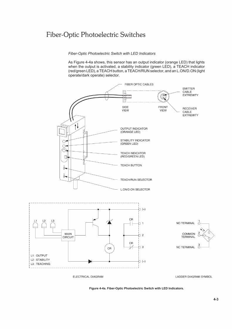
Fiber-Optic Photoelectric Switch with LED Indicators
As Figure 4-4a shows, this sensor has an output indicator (orange LED) that lightswhen the output is activated, a stability indicator (green LED), a TEACH indicator(red/green LED), a TEACH button, a TEACH/RUN selector, and an L.ON/D.ON (lightoperate/dark operate) selector.
Figure 4-4a. Fiber-Optic Photoelectric Switch with LED Indicators.
Fiber-Optic Photoelectric Switches
4-4
Other characteristics of the Fiber-Optic Photoelectric Switch with LED indicators arelisted in Table 4-1a.
CHARACTERISTICS OF THE FIBER-OPTIC PHOTOELECTRIC SWITCH
Table 4-1a. Characteristics of the Fiber-Optic Photoelectric Switch with LED Indicators.
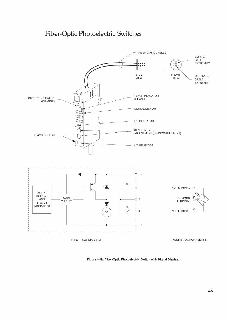
Fiber-Optic Photoelectric Switch with Digital Display
As Figure 4-4b shows, this sensor has a digital display that indicates the incidentlight level or threshold value, as well as the contents of functions during operation.This sensor also has sensitivity adjustment buttons (UP and DOWN buttons), an L/D(light operate/dark operate) button, and a TEACH button. Finally, this sensor has anoutput indicator (orange) that lights when the output is activated, a TEACH indicator(orange), and an L/D (light operate/dark operate) button.
Other characteristics of the Fiber-Optic Photoelectric Switch with digital display arelisted in Table 4-1b.
CHARACTERISTICS OF THE FIBER-OPTIC PHOTOELECTRIC SWITCH
Table 4-1b. Characteristics of the Fiber-Optic Photoelectric Switch with Digital Display.
Fiber-Optic Photoelectric Switches
4-5
Figure 4-4b. Fiber-Optic Photoelectric Switch with Digital Display.
Fiber-Optic Photoelectric Switches
4-6
Sensitivity Adjustments
There are different procedures, called teaching methods, to adjust the sensitivity ofa fiber-optic photoelectric switch.
• Maximum sensitivity setting is used to detect the presence of objects thatcompletely block the sensor light beam, and to detect the presence ofobjects with no background. This method, described in Appendix D, is usedwith the photoelectric switch model with LED indicators.
• With/without object teaching is used for detection of a slight difference inreflection, color discrimination, background objects with unstable reflection,detection of object surface irregularities, and for elimination of backgroundobject influence. This method is used with both photoelectric switch models.
• No-object/Automatic teaching is used when teaching is impossible bystopping the movement of sensing objects, for detection of bright/darkobjects by teaching only with background objects, and for elimination ofbackground object influence. Changes in the incident light level are detectedwithin a certain time interval and the operating point is set at the midpointbetween the maximum and minimum detected levels. This method,described in Appendix D, is used with both photoelectric switch models.
Procedure Summary
In the first part of the exercise, Sensitivity Adjustment, you will adjust the sensitivityof the Fiber-Optic Photoelectric Switch using the With/without object teachingmethod.
In the second part of the exercise, Characteristics, you will observe the ability of theFiber-Optic Photoelectric Switch to detect each surface of the Reflective Block. Youwill also experiment with the light operate/dark operate modes of the photoelectricswitch.
In the third part of the exercise, Sensitivity Adjustment Using the RetroreflectiveSurface of the Reflective Block, you will adjust the sensitivity of the Fiber-OpticPhotoelectric Switch using the With/without object teaching method using theretroreflective surface of the Reflective Block.
EQUIPMENT REQUIRED
Refer to the Equipment Utilization Chart, in Appendix A of this manual, to obtain thelist of equipment required to perform this exercise.
Fiber-Optic Photoelectric Switches
4-7
PROCEDURE
Sensitivity Adjustment
With/without object teaching
G 1. Connect the circuit shown in Figure 4-5, and turn on the DC Power Supply.
Figure 4-5. Circuit using the Fiber-Optic Photoelectric Switch.
Fiber-Optic Photoelectric Switches
4-8
G 2. Adjust the sensitivity of the Fiber-Optic Photoelectric Switch as follow:
• Put the Reflective Block on a white sheet of paper and position theblock so the white plastic surface is on top.
• Aim the sensor sensing face toward the white plastic surface of theReflective Block at a distance of 75 mm (3 in) as shown in Figure 4-5.
• Remove the protective cover of the photoelectric switch.
• If you are using the photoelectric switch model with LED indicators,proceed with the steps in 2.a. If you are using the photoelectric switchmodel with digital display, proceed with the steps in 2.b.
2.a. Photoelectric switch model with LED indicators
• Set the photoelectric switch detection mode to Light operate bysetting its L.ON/D.ON selector to the L.ON position.
• Set the TEACH/RUN selector to the TEACH position.
• The output indicator and the stability indicator should turn off.
• Depress the TEACH button once. The TEACH indicator (red)is lit and the built-in buzzer beeps once.
• Remove the Reflective Block and depress the TEACH buttononce. If the teaching is correct, the TEACH indicator (red) turnsgreen and the built-in buzzer beeps once.
• If the teaching is not correct, the TEACH indicator (red) startsflashing and the built-in buzzer beeps 3 times. Change theposition of the target and the detection distance that have beenset and repeat from the beginning.
• Set the TEACH/RUN selector to RUN to complete the setting.The TEACH indicator (green) turns off. Replace the protectivecover and go to step 3.
Fiber-Optic Photoelectric Switches
4-9
2.b. Photoelectric switch model with digital display
• Set the photoelectric switch detection mode to Light operate bypressing the L/D button so that the L (Light) indicator is lit.
• Depress the TEACH button once. This sets the first detectionpoint (point with a workpiece).
• Remove the Reflective Block and depress the TEACH buttononce. This sets the second detection point (point without aworkpiece).
• Verify that the teaching is correct: the output (orange) indicatorturns on when the Reflective Block is moved past the sensor,while the output (orange) indicator turns off when the ReflectiveBlock is removed.
• Replace the protective cover and go to step 3.
Characteristics
G 3. Test the ability of the Fiber-Optic Photoelectric Switch to detect the varioussurfaces of the Reflective Block.
Leave the photoelectric switch detection mode set to Light operate.
Position the photoelectric switch and the Reflective Block as shown inFigure 4-5 and determine which surfaces are detected by the sensor. Noteyour observations in Table 4-2.
SURFACES
LO (light operate) DO (dark operate)
DETECTEDNOT
DETECTEDDETECTED
NOT
DETECTED
Black Plastic Surface
White Plastic Surface
Matte Black Metallic Surface
Shiny Metallic Surface
Retroreflective Surface
Table 4-2.
G 4. What can you conclude from your observations?
Fiber-Optic Photoelectric Switches
4-10
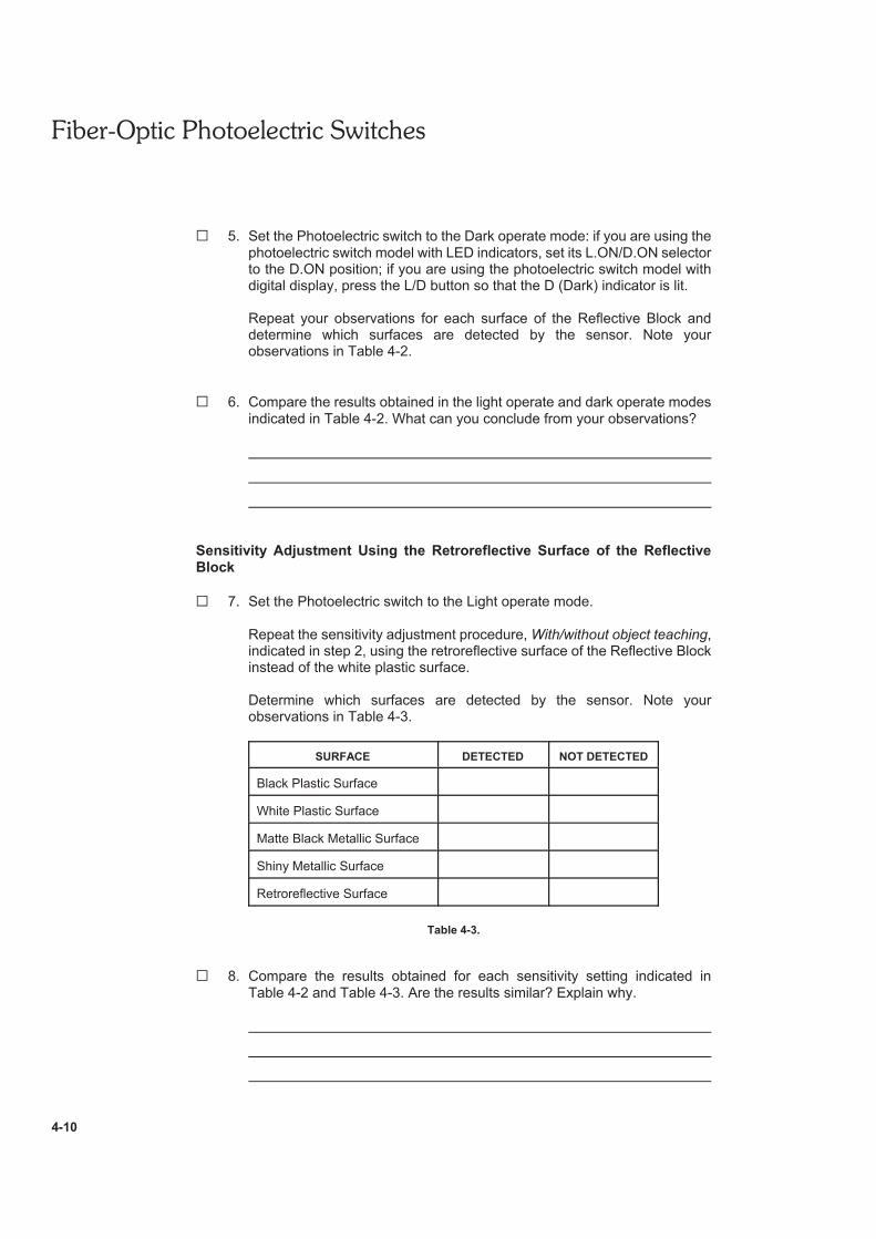
G 5. Set the Photoelectric switch to the Dark operate mode: if you are using thephotoelectric switch model with LED indicators, set its L.ON/D.ON selectorto the D.ON position; if you are using the photoelectric switch model withdigital display, press the L/D button so that the D (Dark) indicator is lit.
Repeat your observations for each surface of the Reflective Block anddetermine which surfaces are detected by the sensor. Note yourobservations in Table 4-2.
G 6. Compare the results obtained in the light operate and dark operate modesindicated in Table 4-2. What can you conclude from your observations?
Sensitivity Adjustment Using the Retroreflective Surface of the ReflectiveBlock
G 7. Set the Photoelectric switch to the Light operate mode.
Repeat the sensitivity adjustment procedure, With/without object teaching,indicated in step 2, using the retroreflective surface of the Reflective Blockinstead of the white plastic surface.
Determine which surfaces are detected by the sensor. Note yourobservations in Table 4-3.
SURFACE DETECTED NOT DETECTED
Black Plastic Surface
White Plastic Surface
Matte Black Metallic Surface
Shiny Metallic Surface
Retroreflective Surface
Table 4-3.
G 8. Compare the results obtained for each sensitivity setting indicated inTable 4-2 and Table 4-3. Are the results similar? Explain why.
Fiber-Optic Photoelectric Switches
4-11
Note: Other teaching methods are described in Appendix D.
G 9. Turn off the DC Power Supply, and remove all leads.
CONCLUSION
In this exercise, you were introduced to fiber-optic photoelectric switches. Youlearned how and when they are used, their advantages and disadvantages.
You adjusted the sensitivity of the Fiber-Optic Photoelectric Switch using theWith/without object teaching method. You observed its ability to detect the presenceof various reflective surfaces in the light operate and dark operate modes ofoperation. By adjusting the sensitivity using the retroreflective surface of theReflective Block instead of the white plastic surface, you observed that thisphotoelectric switch is capable of discrimination.
REVIEW QUESTIONS
1. For which applications are the fiber-optic photoelectric switches designed for?
2. Explain why fiber-optic photoelectric switches can be easily obstructed by dirt orother opaque substances.
3. Which teaching method should be used to adjust the sensitivity of the Fiber-Optic Photoelectric Switch to detect the presence of objects with nobackground?
Fiber-Optic Photoelectric Switches
4-12
4. Explain why the signal transmitted by fiber-optic cables is unaffected byelectromagnetic interference and vibration.
5. What cause the losses in light intensity in fiber-optic cables?