journa l homepage: www.e lsev ier .com/ locate /sna
evelopment and characterization of a packaged mechanically actuatedicrotweezer system
rock A. Westera,b,c,d,∗, Swaminathan Rajaramand, James D. Rossd, Michelle C. LaPlacaa,c,ark G. Allenb,d
Laboratory for Neuroengineering, Georgia Institute of Technology, United StatesMicroelectronics Research Center, Georgia Institute of Technology, United StatesEmory University School of Medicine, United StatesNanoGrip Technologies, Inc., United States
r t i c l e i n f o
rticle history:eceived 25 September 2010eceived in revised form2 December 2010ccepted 7 January 2011vailable online 5 March 2011
a b s t r a c t
This paper presents the successful design, modeling, fabrication, packaging, and characterization of amechanically actuated micro-electro-mechanical-systems (MEMS) microtweezer. This complete andmodular MEMS system has minimal manufacturing complexity and can be augmented to any stan-dard micromanipulator or positioning system. The microtweezer is mechanically actuated and hencehas minimal impact on the surrounding microenvironment, a key consideration for micromanipula-tion. The microtweezer components are fabricated utilizing standard electroplating based processes. The
eywords:EMSicrotweezers
ackagingicromanipulation
iological interfacing
microtweezer is functionally attached to a tether-cable system packaged within a stainless steel luerneedle, which can be mounted to a manual controller with a luer interface. The controller, which pro-vides axial rotational movement of the microtweezer, can be attached to any positioning stage to allow5+ degrees of movement freedom. Mechanical modeling and characterization of the system shows thatprecise and controlled tool actuation is achieved with tip closing forces averaging 360 mN over an actu-ation range of 125 �m. The system’s performance and ease of use can provide the means to create and
xperi
echanical actuation enhance a multitude of e
. Introduction
To allow for experimentation and interfacing with a variety ofaterial, chemical, and biological microenvironments, there have
een a number of platform based (microelectrode arrays, lab-on-a-hip devices, platform microfluidics and sensors) and non-platformased (insertable-shank electrodes, microgrippers, microtweezers)icro-electro-mechanical system (MEMS) devices created [1–3].hile platform MEMS devices allow for a multitude of interfacing
pplications, the ability to manipulate or position microstructuress limited, as are the degrees of movement freedom. However,
icrotweezers and similar microtools offer an attractive optiono meet the increasing need to simultaneously interface withnd manipulate micro-sized objects such as microfabricated and
aterial constructs, optical fibers and crystals, cells and tissues,
uorescent and positional markers, and biological structures.Independent of application, one of the most critical aspects
o MEMS device design and efficacy is developing an interfacing
∗ Corresponding author at: Laboratory for Neuroengineering, Georgia Institute ofechnology, 313 Ferst Drive, Atlanta, GA 30332, United States. Tel.: +1 404 944 3795.
mechanism, or package, that provides important application-dependent functionalities, such as physical and environmentalprotection, translation of mechanical movement, fluid transfer, orelectrical connectivity [4]. Implementation of this packaging isespecially important for non-platform systems due to intendedor unintended movement, which can complicate the design andreduce stability in functional and physical connectivity. Packagingconsiderations in MEMS, semiconductors, and biomedical devicesis critical and can account for over 70% of the cost and time devel-opment of the final device [5].
The packaging system presented in this paper utilizes a mod-ular, segmented mechanical mechanism, and allows previouslydeveloped MEMS microtweezers [6,7] to be used in a variety ofenvironments and applications. As the tool presented here pro-vides acuity of control, repeatability, and miniaturization, it canalso play a more direct role in experimentation, such as isolatingmaterial and tissue samples for chemical and mechanical char-acterization and manipulation. Microtweezers tailored to these
applications can allow for a significant variety of experimen-tal preparations previously not thought possible. In addition tobenefiting MEMS interfacing and assembly, microstructure posi-tioning and manipulation, and biomedical research, these devicescould be adapted to support remote, minimally invasive surgi-
B.A. Wester et al. / Sensors and Actuators A 167 (2011) 502–511 503
F tem. Tm withc ezer t
cs
mtalH(mtdi[tf(toree
[pmcasoactt
saaatttadp
ig. 1. (A) Photo of the current microtweezer packaging and manual controller sysanual mechanical controller consists of a docking station, a manual linear actuator
onnect them. (B) X-ray of assembled microtweezer. (C) SEM images of various twe
al and dissection procedures, both in a clinical and experimentaletting.
For devices that actively and mechanically interface withicroenvironments for the purpose of micromanipulation, elec-
rical, thermal, piezoelectric, laser, or shape memory alloy basedctuation mechanisms have been historically utilized due to estab-ished actuation techniques and microfabrication strategies [8–17].owever the use of these mechanisms have several limitations:
1) material limitations due to the required use of silicon-basedicrofabrication techniques to achieve electrically induced actua-
ion, (2) mechanical and electrical variation from device to deviceue to inherent limitation in the actuation mechanism (i.e. the tun-
ng of a piezo or electro-thermal driving signal for an actuator)18], (3) modular construction of the microdevice and the elec-rical packaging can be expensive and unreliable, (4) interferencerom the microenvironment can alter or inhibit device performancei.e. aqueous environment, heated systems, etc.), (5) limited actua-ion range or resolution, and (6) most importantly, these electrical,ptical and thermal devices can dissipate heat into the local envi-onment, as well as generate unintended and potentially damaginglectrostatic fields and currents that limit the device’s applications,specially when introduced into a biological environment.
The microtweezers reported in this paper employ a proprietary19] micro-mechanical actuation mechanism based on position,recluding the need for thermal, optical or electrically sensitiveaterials, or for complex controllers. Tool tips are opened and
losed due to their position within a sleeve, or box, and the rel-tive motion of these two components can be delivered through aingle axis direct-drive system. This actuation method is similar tother microtools [20], but our microtweezers: (1) have isolation ofxial rotation and vertical translation; (2) benefit from microfabri-ation processes that allow the patterning of smaller features at theweezer tips; and (3) modular fabrication allows for the potentialo integrate friction-removing coatings [21,22].
This system consists of a luer based tool packaging and dockingtation, which allows plug-n-play docking of various microtoolss well as rotation along the microtool axis. Remote actuation ischieved utilizing an actuator, or micrometer/motor attached totether-cable system. Because such a mechanism can be con-
rolled either by a knob or motor, it could benefit from both
he inherent tactile precision of a human user, or the automa-ion of a computerized controller. These components can augmentny standard micropositioner, allowing positioning in three-plusimensions, plus the tool actuation and rotation. Given the sim-licity of design and manufacturing requirements, these potentially
he microtweezer is mechanically packaged with a stainless steel luer needle. Thea micrometer knob, and a nitinol tether-cable system to physically and functionallyips.
disposable tools address needs in a variety of bio-medical, clinical,and experimental markets.
2. Device design and integration
2.1. MEMs microtweezer system
The microtweezer system is composed of four main compo-nents, (1) a packaged microtweezer tool, (2) a docking station, (3) amechanical linear actuator, and (4) a positioning stage (Fig. 1). Themicrotool is a microfabricated MEMS microtweezer structure thatis attached to a luer needle. Inside the housing of the luer nee-dle is a spring loaded button that is functionally and physicallyconnected to the microfabricated MEMS structure. This luer nee-dle based packaging allows for mounting onto the docking station,which has a male luer fitting. The docking station provides rota-tional functionality of the microtool about the luer needle axis, aswell as mounting of the system onto a stage using a custom mount-ing bracket. A linear actuator drives a spring-loaded rod through thedocking station to drive the spring loaded button of the microtoolpackage, which actuates the microtweezer. This linear actuator canbe a manually driven micrometer head, stepper motor system, orany other motor actuator system. Such a system design allows formodularity and the ability to augment the microtool system to avariety of manual and automated positioning stages.
2.2. MEMS microtweezer design
Our previous work demonstrated the successful fabrication ofa prototype microtweezer, which consisted of two main compo-nents: (1) a tool body that contains the tool beams and tips, and(2) a sleeve, or box that houses the tool body in an inner con-strictive channel that physically engages the tool beams to closethe tips (Fig. 2) [6,7]. Thus, these microtweezers use externallyapplied linear mechanical motion to achieve high-resolution tipcontrol as the tool tips are opened and closed due to their positionwithin the moving box. As the box moves forward, it also providesadditional self-alignment of the tips, which is achieved by exert-ing equal forces from each side of the channel, and by the channelconstricting vertical movement of the tweezer beams.
The box channel contains multiple segments of varying innergeometries as shown in Fig. 2: a regular drive section, and an over-drive section which provides additional actuation range to allowtool tips with larger separations between them to close completely,as well as multiple closing regimens with differing speeds. This sec-
504 B.A. Wester et al. / Sensors and Actuators A 167 (2011) 502–511
F l tipst edle ab uring
tmgiacrdtor
fpdtfieiotcFvbrsipa
im
ig. 2. (A) Schematic of MEMS box and tweezer showing key features, (B) box and tooo tip closing), and (C) mechanical luer-needle packaging of microtweezer with neutton resulting in a point contact, which limits torsional loading on the drive rod d
ion additionally allows for increasing the force of closure to allowanipulation of heavier samples. The 2D patterned inner-channel
eometries are relatively unconstrained, allowing a range of clos-ng schemes to be employed for instrument customization, suchs fast closing of bulk microtweezer tip separation, and then slowlosing of the remaining tip separation prior to tip contact. Geomet-ic tuning of the beams and channel leads to a distinct advantage inevice design: a box movement of 1 �m translates into 300 nm ofip closure, providing a mechanical advantage, or 3:1 actuation res-lution ratio. This tunable advantage lends itself to achieving highesolution tip movement in the submicron-scale.
The microtweezer body, tips, and box were originally micro-abricated together in the same sample to eliminate the need forost-processing assembly, to limit opportunity for tool damageuring assembly, and to ensure body and box alignment [6]. Inhe current manufacturing process, the box and tool body/tips areabricated separately. Separate construction reduces the complex-ty of each fabrication process, allows direct process refinement,nables addition of finer features (e.g. over-drive section), andncreases yield. While assembly of the two parts is required, the usef machined jigs that align the parts facilitates the directed inser-ion of the tweezer into the box and multiple insertions in parallelan be performed with the machined jigs increasing throughput.abricating the two components separately also allows for a moreersatile selection of materials for the box and body (e.g. siliconoxes and metal microtweezers), tool tip geometries, and sepa-ate post-fabrication processing for tip sharpening, patterning andurface treatments (to allow for potential elimination of materialncompatibilities). This modular design also creates a platform that
ermits future integration of various sensors on the tool tips, suchs surface microelectrodes, position sensors, and strain gauges.
The selection of materials is important not only for the mechan-cal and material properties, such as tensile strength, elastic
odulus, and surface attraction, but also for biological compati-
actuation with arrow size demonstrating a 3:1 actuation ratio (linear box movementnd drive rod. The drive shaft (red) meets a rounded interface on the outside of theaxial rotation of the microtweezer.
bility. The microtool body fabricated in this work has tips that are40 �m wide and 20 �m thick. The body and box channel widths are300 �m and 330 �m, respectively.
2.3. MEMS packaging design
The mechanical microtool packaging consists of a physical luerinterface between the microtool and the docking station, andincludes an internal mechanism to functionally translate actuationfrom the docking station to the microtweezer box (Fig. 1).
The packaged microtool consists of three main components: (1)a female luer hub, which allows for connection with the dock-ing station and also houses the micro-drive mechanism, (2) anattached stainless steel hollow needle which provides both a phys-ical structure in which to adhere the fixed body of the microtool,and a durable tract in which to allow translation of precise linearactuation of the drive system to the microtool, and (3) the internalmicro-drive mechanism which consists of a spring-loaded buttonand a drive rod that runs through the needle cannula from theneedle tip to the luer hub where it is seated into the button.
Because both fixed position and moving elements were requiredfor relative motion, a tether-cable system was employed using thecannula of the stainless steel needle as the tether, and the drive rodas the cable. In addition to being an inexpensive, standardized dock-ing component, the luer hub of the stainless steel needle houses theinternal mechanism to allow translation of external linear actua-tion from the docking station to the microtweezer box. The MEMSmicrotweezer box and body are centered on the needle cannulaaxis, and the end of the microtweezer body is attached to a rect-
angular micro-milled notch in the outer face of the needle tip. Themicrotweezer box, which houses the body, is attached to the endof the drive rod. The spring loaded plastic button is held in place bya friction-locked rubber o-ring. This button is presented within thehub so that it can be contacted and linearly actuated by the output
B.A. Wester et al. / Sensors and Actuators A 167 (2011) 502–511 505
F latedg y), asl f thec
stptc
laps
Fm
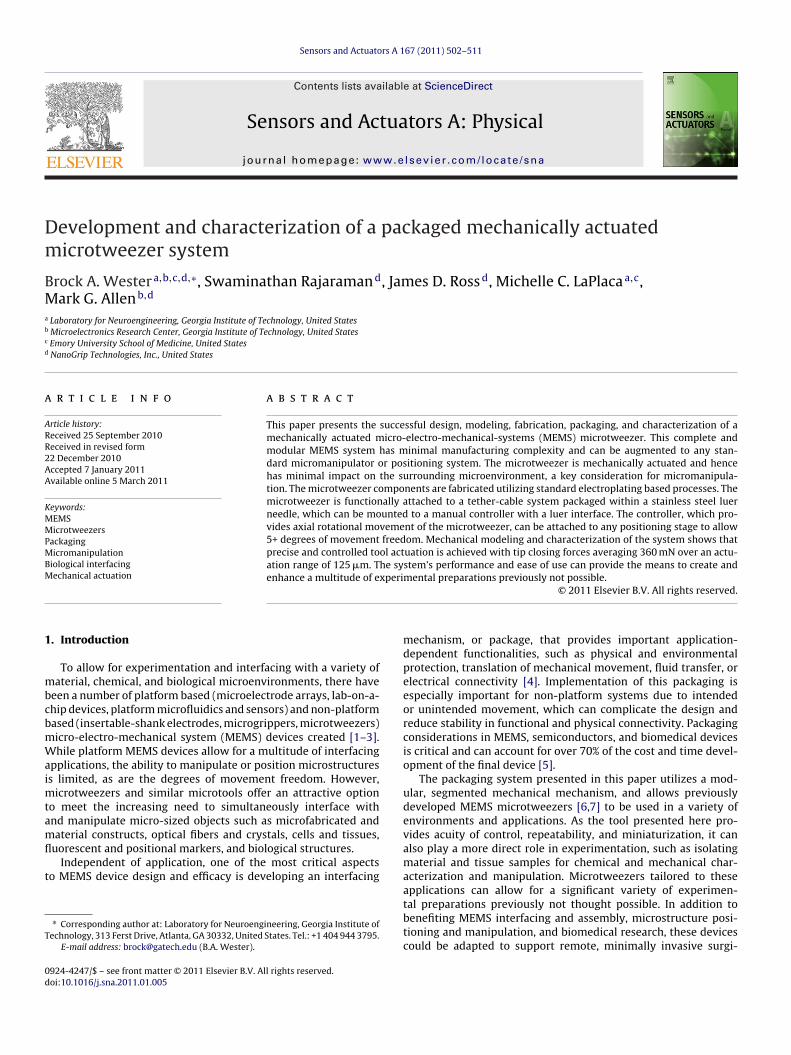
ig. 3. (A) Cross-section of docking station schematic showing the rotationally isoear and attached luer shaft (blue) can rotate independently with the housing (greoading on the spring loaded button of the luer-needle package. (B) Cross-section oolor in the figure caption, the reader is referred to the web version of the article.)
haft of the docking station. The motion of the drive rod relativeo the needle shaft is translated to the tool box, which is then dis-laced relative to the tool body. Through this motion, the walls ofhe box channel make contact with the tool tips causing them tolose.
This package design modality, which translates micron scaleinear controller actuation into sub-micron scale resolution tipctuation, allows for easy, plug-n-play docking of tools. Thisackage, which contains internally protected elements, and atand-alone modular design, also reduces the complexity inher-
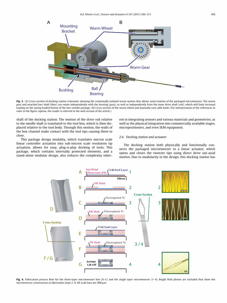
ig. 4. Fabrication process flow for the three-layer microtweezer box (A–G) and theicrotweezer construction at fabrication steps 2–4. All scale bars are 400 �m.
worm system that allows axial rotation of the packaged microtweezer. The wormwell as independently from the inner drive shaft (red), which will limit torsional
worm wheel and manually turn-able knob. (For interpretation of the references to
ent in integrating sensors and various materials and geometries, aswell as the physical integration into commercially available stages,micropositioners, and even SEM equipment.
2.4. Docking station and actuator
The docking station both physically and functionally con-nects the packaged microtweezer to a linear actuator, whichopens and closes the tweezer tips using direct drive uni-axialmotion. Due to modularity in the design, this docking station has
single layer microtweezer (1–4). Bright field photos are included that show the
506 B.A. Wester et al. / Sensors and Actuators A 167 (2011) 502–511
e ass
mdadpt
wtYaorda
ma
aaollsimwtbttaa
2
maMu
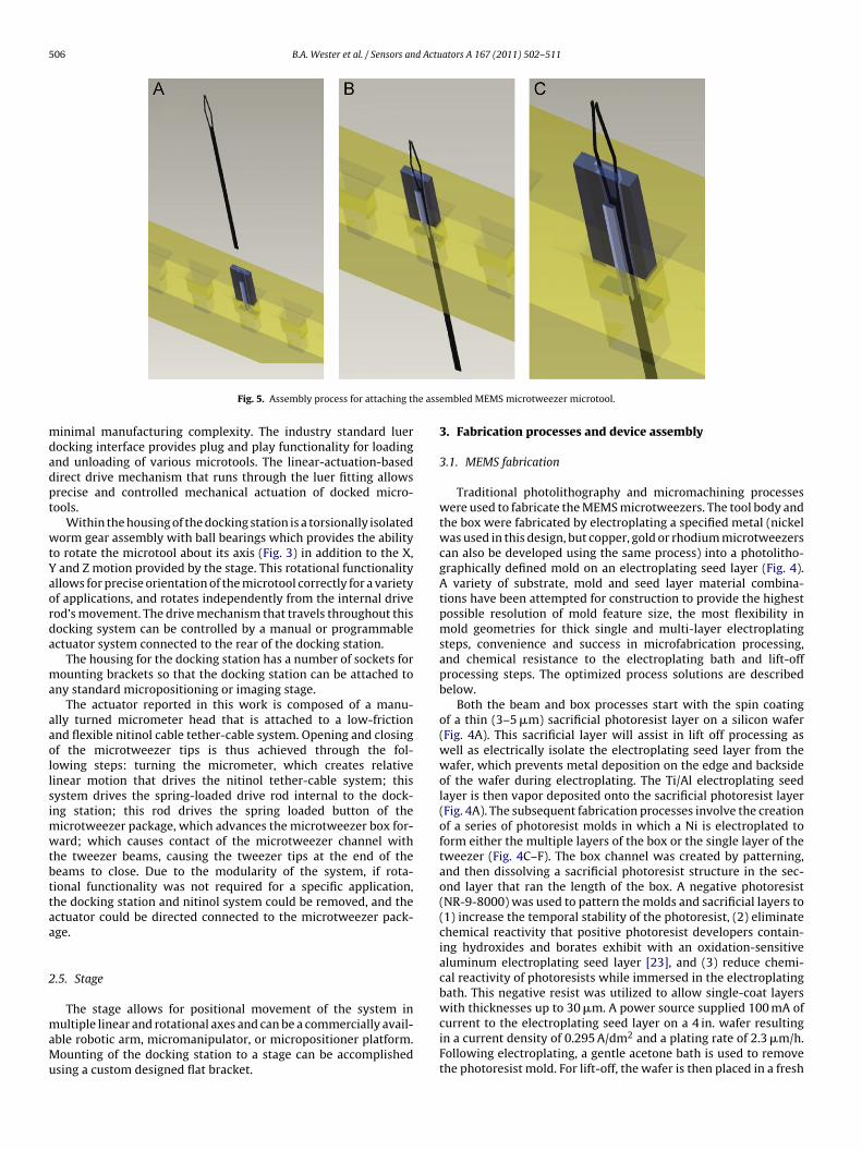
Fig. 5. Assembly process for attaching th
inimal manufacturing complexity. The industry standard luerocking interface provides plug and play functionality for loadingnd unloading of various microtools. The linear-actuation-basedirect drive mechanism that runs through the luer fitting allowsrecise and controlled mechanical actuation of docked micro-ools.
Within the housing of the docking station is a torsionally isolatedorm gear assembly with ball bearings which provides the ability
o rotate the microtool about its axis (Fig. 3) in addition to the X,and Z motion provided by the stage. This rotational functionality
llows for precise orientation of the microtool correctly for a varietyf applications, and rotates independently from the internal driveod’s movement. The drive mechanism that travels throughout thisocking system can be controlled by a manual or programmablectuator system connected to the rear of the docking station.
The housing for the docking station has a number of sockets forounting brackets so that the docking station can be attached to
ny standard micropositioning or imaging stage.The actuator reported in this work is composed of a manu-
lly turned micrometer head that is attached to a low-frictionnd flexible nitinol cable tether-cable system. Opening and closingf the microtweezer tips is thus achieved through the fol-owing steps: turning the micrometer, which creates relativeinear motion that drives the nitinol tether-cable system; thisystem drives the spring-loaded drive rod internal to the dock-ng station; this rod drives the spring loaded button of the
icrotweezer package, which advances the microtweezer box for-ard; which causes contact of the microtweezer channel with
he tweezer beams, causing the tweezer tips at the end of theeams to close. Due to the modularity of the system, if rota-ional functionality was not required for a specific application,he docking station and nitinol system could be removed, and thectuator could be directed connected to the microtweezer pack-ge.
.5. Stage
The stage allows for positional movement of the system inultiple linear and rotational axes and can be a commercially avail-
ble robotic arm, micromanipulator, or micropositioner platform.ounting of the docking station to a stage can be accomplished
sing a custom designed flat bracket.
embled MEMS microtweezer microtool.
3. Fabrication processes and device assembly
3.1. MEMS fabrication
Traditional photolithography and micromachining processeswere used to fabricate the MEMS microtweezers. The tool body andthe box were fabricated by electroplating a specified metal (nickelwas used in this design, but copper, gold or rhodium microtweezerscan also be developed using the same process) into a photolitho-graphically defined mold on an electroplating seed layer (Fig. 4).A variety of substrate, mold and seed layer material combina-tions have been attempted for construction to provide the highestpossible resolution of mold feature size, the most flexibility inmold geometries for thick single and multi-layer electroplatingsteps, convenience and success in microfabrication processing,and chemical resistance to the electroplating bath and lift-offprocessing steps. The optimized process solutions are describedbelow.
Both the beam and box processes start with the spin coatingof a thin (3–5 �m) sacrificial photoresist layer on a silicon wafer(Fig. 4A). This sacrificial layer will assist in lift off processing aswell as electrically isolate the electroplating seed layer from thewafer, which prevents metal deposition on the edge and backsideof the wafer during electroplating. The Ti/Al electroplating seedlayer is then vapor deposited onto the sacrificial photoresist layer(Fig. 4A). The subsequent fabrication processes involve the creationof a series of photoresist molds in which a Ni is electroplated toform either the multiple layers of the box or the single layer of thetweezer (Fig. 4C–F). The box channel was created by patterning,and then dissolving a sacrificial photoresist structure in the sec-ond layer that ran the length of the box. A negative photoresist(NR-9-8000) was used to pattern the molds and sacrificial layers to(1) increase the temporal stability of the photoresist, (2) eliminatechemical reactivity that positive photoresist developers contain-ing hydroxides and borates exhibit with an oxidation-sensitivealuminum electroplating seed layer [23], and (3) reduce chemi-cal reactivity of photoresists while immersed in the electroplatingbath. This negative resist was utilized to allow single-coat layers
with thicknesses up to 30 �m. A power source supplied 100 mA ofcurrent to the electroplating seed layer on a 4 in. wafer resultingin a current density of 0.295 A/dm2 and a plating rate of 2.3 �m/h.Following electroplating, a gentle acetone bath is used to removethe photoresist mold. For lift-off, the wafer is then placed in a fresh
B.A. Wester et al. / Sensors and Actuators A 167 (2011) 502–511 507
F MEMi of the
al
3
ftcub
piatnwttodlcb
TTc
ig. 6. Assembly process for the luer needle package and for attaching the assembleds placed in a notch at the end of the luer needle and glued, and the protruding end
cetone bath with sonication to remove the sacrificial photoresistayer and ablate the thin film electroplating seed layer.
.2. MEMS assembly
After the individual microtweezer body/tips and boxes wereabricated, they were assembled by inserting the end of the beamhrough the channel while imaged under an optical stereoscope, alamped jig to hold the boxes, and hand-held forceps to manip-late and position the tweezer body to be inserted into theox.
Several jigs were constructed to facilitate device assembly inarallel (Fig. 5). The order of assembly was important due to nest-
ng of the spring loaded button inside the housing of the luer needlend its physical connection with the MEMS components that are onhe end of the luer needle. One end of the cable was inserted into aotch in the button and adhered with epoxy. A compression springas inserted over the cable and nested over an outside groove in
he button. The opposite end of the cable was then advanced intohe luer housing and through the needle cannula until it comes
ut the end of the needle. An o-ring was then placed into the nee-le housing and seated by inserting a male luer fitting into the
uer hub. This seated o-ring slightly compresses the spring, andreates a physical stop that controls the range of motion for theutton.
able 1able of calculated values for modeling of tweezer beam actuation. This table shows thonditions and values during both drive and overdrive scenarios for actuation.
Calculated values Initial valuea
Shoulder angle: ˚ ˚0
Upper arm vertical vector: AU AU0 = CU·cos(˚0)Upper arm horizontal vector: BU BU0 = CU·sin(˚0)Elbow angle – upper arm: �U �U0 = 90 − ˚0
a Assumes tweezer beams and channel notch at initial contact point.b When action turns from drive to overdrive.
S microtweezer microtool to the assembled package. The body of the microtweezercable is glued to the notch on the underside of the box.
The assembled MEMS device was then attached to the luer nee-dle tool packaging by gluing the microtweezer body to the end ofthe needle, and the drive rod running through the needle cannulato the microtweezer box (Fig. 6). This simple interface betweenthe package and MEMS device allows for reuse of the luer packagesystem following detachment of the tweezer and box.
4. Mechanical modeling and evaluation
4.1. Microtweezer tip actuation modeling
Geometric modeling of the microtweezer tips allows for com-parisons between theoretical predictions and experimental results,facilitating substantive modifications for subsequent design itera-tions. The microtweezer tips are composed of two beam structureswith rectangular cross-sections. Because of the micro-scale dimen-sions of the device, and the same dimensional magnitude for boththe width and thickness of the beam, the strength and mechanicsof the tip motion can be modeled using beam theory [24–29]. The
cross-sectional dimensions, material moduli, and predicted con-tact locations of the box channel wall and tweezer beams can beused to predict the geometries of the tweezer beams and tweezertips throughout the actuation range of the box. Geometric equa-tions were then solved to create an expected actuation of the
e pertinent values in the model, and the equations used to determine the initial
Fig. 7. Schematic of the tweezer body and beams housed within the channel, andthe pertinent geometric dimensions that are considered when calculating the pre-dicted actuation behavior. Static dimensions are highlighted in red, and dynamicdit
tgb
drbwr1
Fm
F =L3
(6)
Strain energy (U) was calculated as (3) from the known quantitiesof the point of bend to moment length (l), elastic modulus (E), andinertia (I). After moving the force load into the integral (4), and
imensions, which change value over the course of actuation, are in black. (Fornterpretation of the references to color in the figure caption, the reader is referredo the web version of the article.)
weezer beams based on the beam geometries, the box channeleometries, and the box location relative to the tweezer body andeams.
Tweezer and box geometries (Table 1, Fig. 7) could then beesigned to provide nearly linear closing of the tips through bothegular and overdrive actuation. The separation of the tips is shownased on the actuation distance of the box (Fig. 8). For a tweezer
ith a tip separation of 330 �m, a box actuation of 1.09 mm is
equired to close the tips, and this mechanical advantage of roughly:3 can allow increased actuation resolution.
ig. 8. Modeling data for separation of tips based on actuation distance of box, andaximal force loading seen at the inner face of the tweezer.
ators A 167 (2011) 502–511
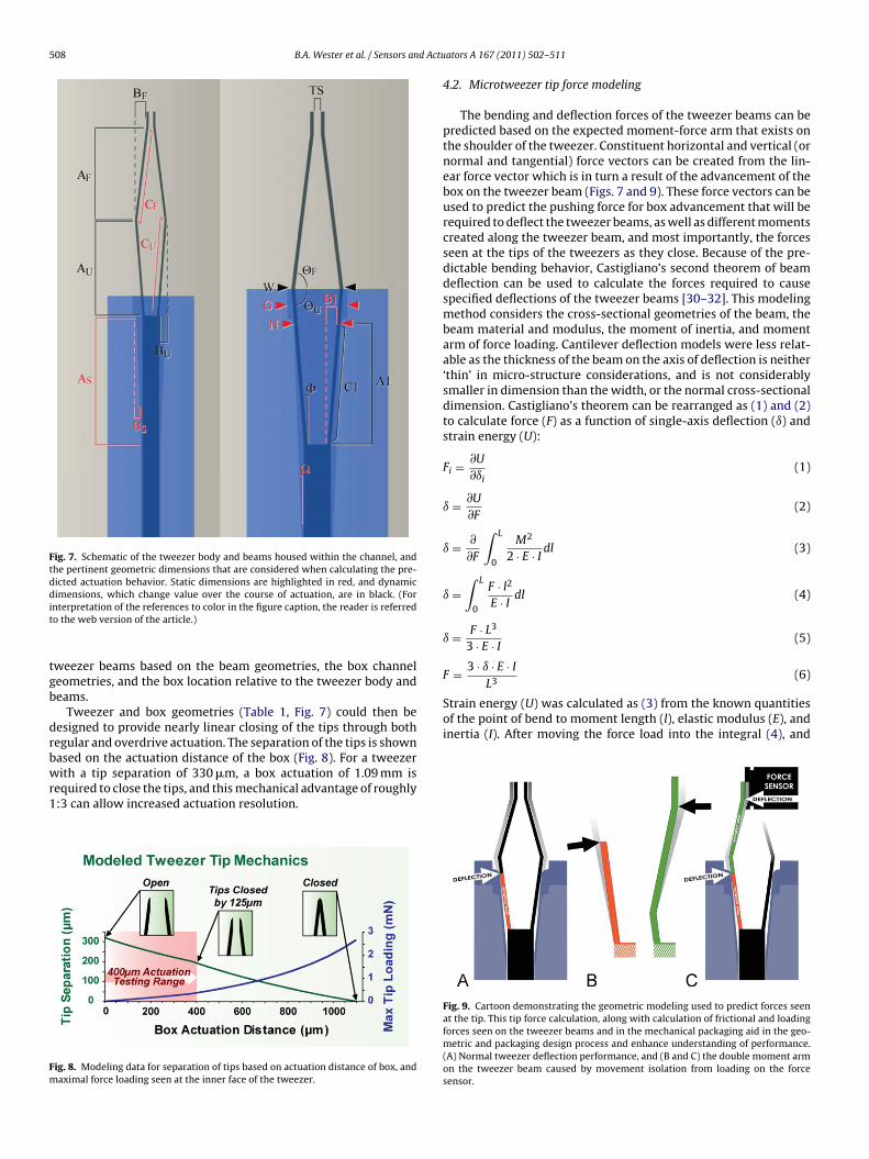
4.2. Microtweezer tip force modeling
The bending and deflection forces of the tweezer beams can bepredicted based on the expected moment-force arm that exists onthe shoulder of the tweezer. Constituent horizontal and vertical (ornormal and tangential) force vectors can be created from the lin-ear force vector which is in turn a result of the advancement of thebox on the tweezer beam (Figs. 7 and 9). These force vectors can beused to predict the pushing force for box advancement that will berequired to deflect the tweezer beams, as well as different momentscreated along the tweezer beam, and most importantly, the forcesseen at the tips of the tweezers as they close. Because of the pre-dictable bending behavior, Castigliano’s second theorem of beamdeflection can be used to calculate the forces required to causespecified deflections of the tweezer beams [30–32]. This modelingmethod considers the cross-sectional geometries of the beam, thebeam material and modulus, the moment of inertia, and momentarm of force loading. Cantilever deflection models were less relat-able as the thickness of the beam on the axis of deflection is neither‘thin’ in micro-structure considerations, and is not considerablysmaller in dimension than the width, or the normal cross-sectionaldimension. Castigliano’s theorem can be rearranged as (1) and (2)to calculate force (F) as a function of single-axis deflection (ı) andstrain energy (U):
Fi = ∂U
∂ıi(1)
ı = ∂U
∂F(2)
ı = ∂
∂F
∫ L
0
M2
2 · E · Idl (3)
ı =∫ L
0
F · l2
E · Idl (4)
ı = F · L3
3 · E · I(5)
3 · ı · E · I
Fig. 9. Cartoon demonstrating the geometric modeling used to predict forces seenat the tip. This tip force calculation, along with calculation of frictional and loadingforces seen on the tweezer beams and in the mechanical packaging aid in the geo-metric and packaging design process and enhance understanding of performance.(A) Normal tweezer deflection performance, and (B and C) the double moment armon the tweezer beam caused by movement isolation from loading on the forcesensor.
B.A. Wester et al. / Sensors and Actu
Fig. 10. Measured force on inner face of closing tweezer tip. Average maximal forcesfrom 125 �m tip deflections were 0.321 mN, 0.367 mN, 0.339 mN, and 0.335 mNfrci
ic
cdt
Fpitw
or oscillating, fast oscillating, slow close/open, and stepped close/open actuationsespectively. The dashed blue line denotes the maximal force calculated for a 125 �mlosing. (For interpretation of the references to color in the figure caption, the readers referred to the web version of the article.)
ntegrating with respect to the moment length (5), the equation
an be re-arranged to determine force.
A conservative application of these equations that used staticalculations of moment arm length and values of deflection pre-icted from the geometric modeling, provided maximal forces forweezer beam deflection throughout the actuation cycle. Applied
ig. 11. (A) Stereoscopic and microscopic photographs demonstrating the wide range ofositioning MEMS devices and material samples as well as interfacing with biological sam
s demonstrated in a series of photographs. The same tweezer beam is labeled in pink in ehickness of 25 �m, and beam widths of 40 �m, and all scale bars are 500 �m. (For interpeb version of the article.)
ators A 167 (2011) 502–511 509
to a double moment-arm model of tweezer actuation (Fig. 9), max-imal forces of roughly 358 �N are expected to be seen at the innerface of the tweezer tip during a closing regimen of 125 �m.
4.3. Microtweezer tip force characterization
Following assembly of the packaged MEMS devices, dockingstation, and actuator, the forces exerted by the inner faces of thetweezer tips were measured under a variety of actuation schemesusing the MTS NanoUTM system (Oak Ridge, TN) (Fig. 10). Quicklyoscillating tip deflections of 125 �m (oscillating period for 250 �mopen-close movement averaged less than 1.5 s) delivered via themanual actuator showed average maximal forces of 367 �N witha standard deviation of 1.1 �N, which compares well with themodeled force in the previous section. The maximal static forcescalculated from the double-moment arm model compare well withthese measured forces (Fig. 11).
These measured forces suggests a beam spring constant of2.936 N/m for this actuation regimen. While this small springconstant enables manipulation of delicate microstructures like bio-logical constructs, the tip force is strong enough to overcome theadhesion of cells to substrates [33] and to lift solid structures over10 mg. With over-actuation, which would cause increased inner-tip face forces and noticeable beam deflection, far heavier objectscould be lifted by our microtweezers.
4.4. Microtweezer box actuation force modeling
Data from both measured tweezer tips forces and mechanicalmodeling were used to predict static and kinetic frictional loading(Fig. 10) at the tweezer beam–box channel interface. Point con-tacts were assumed for both drive (rounded drive contact, lineartweezer beam) and over-drive conditions (flat over-drive contact
applications for microtweezers with varying tip styles. Microtweezers are shownples. (B) The continuous rotational functionality of the microtweezer about its axisach photo to assist in visualizing the rotation. All microtweezers shown here have
retation of the references to color in the figure caption, the reader is referred to the
5 d Actu
wrmaalatcfil4e
wot2
5
tfmiidtadddis
6
pcatImmseia
ebmtnwic
imspa
[
[
[
[
[
[
[
[
[[
[
10 B.A. Wester et al. / Sensors an
all, pointed tweezer beam elbow). Over 400 �m of box actuationesulting in 125 �m of tweezer tip closing, with a calculated firstoment arm loading of 341 �N on the upper arm of tweezer beam,
nd a shoulder angle of 3.45◦, maximal frictional forces of 4.832 mNre expected normal to tweezer beam deflection angle. The calcu-ated tweezer beam moment and frictional loading for this 400 �mctuation suggests a minimal forward force of 4.835 mN is requiredo advance the box. Because the tweezer beam moment arm lengthhanges over the course of actuation, a linear spring constant is dif-cult to calculate due to the cubic relationship between moment
ength and force. A semi-linear spring constant region over the00 �m box actuation suggests a spring constant of 12.09 mN/mmxists on the first moment arm.
For the MEMS luer-needle packaging, these calculated forcesere used to determine the minimal spring rate (k) required
f the spring-loaded button to overcome slip-stick across theweezer beam–box channel interface. A spring with a constant of1.0 mN/mm was selected for the luer packaging.
. Manipulation of microstructures and samples
Attaching the microtweezer system to a Signatone (Lucas Signa-one, Gilroy, CA) micromanipulator with an additional control knobor tweezer actuation (Fig. 11) has allowed for use in a variety of
anipulation and positioning applications. Coupled with this prob-ng station, the microtweezer system has the ability to manipulatemage markers, crystals, and other small structures, as well as largeevices such as MEMS stators and microgears. This positioning sys-em has also been used to precisely direct the microtool’s locationnd use within cell cultures, and to micromanipulate a variety ofevices and biological samples (Fig. 7). Due to the spring-loadedirect drive mechanism of the MEMS packaging, the microtweezerevice performance is not significantly affected while immersed
n aqueous solutions which is a significant advantage over currentolutions in micromanipulation.
. Conclusion
A fully packaged mechanically actuated microtweezer system isresented in this paper. This system relies on a mechanical micro-am mechanism to actuate the microtool tips. The microtweezersnd the sleeve they sit in are both fabricated using standard elec-roplating processes providing potential for multitude of materials.n addition to providing enhanced functionality and ease of attach-
ent to micromanipulators and micropositioners, this system hasultiple advantages over previously developed systems including
implified design, durability, flexibility, and modularity. Due to itslegant device design, this system provides a platform in which tontegrate additional functionality and sensors that can enhance itspplication space.
No change in tweezer performance was observed following sev-ral micromanipulation operations, and future cycle testing coulde utilized to verify device consistency and longevity. Given theaterial composition and mechanics, the longevity of the nickel
ool is generally expected to be comparable with silicon based alter-atives [29]. Metals have higher flaw tolerance than ceramics, andill not mechanically or functionally fail when the yield strength
s surpassed from localized stresses and strains that result fromomplex and unpredictable loading conditions [30].
Characterization of the system shows that mechanical model-
ng can be used successfully to predict tweezer performance. This
odeling can aid in tailoring the tweezer geometries and dimen-ions for specific applications, and the material and mechanicalroperties of the MEMS packaging components. Prescribed, repeat-ble actuations and forces can be induced with the microtool tips
[
[
ators A 167 (2011) 502–511
even with the use of a manual controller, and the mechanicalactuation mechanism allows for introduction into aqueous and bio-logical environments. This can allow this system, for example, to beused to induce prescribed biaxial compression loading onto cellsin tissue or to microposition electrically and thermally sensitivecomponents during micro-assembly procedures [34]. Overall, thissystem’s performance and ease of use can provide the means to cre-ate and enhance a multitude of experimental preparations in thematerial, semiconductor, and biomedical engineering fields.
Acknowledgments
The authors wish to thank Scott Bair and Jevin Scrivens Ph.D.for their support with packaging and mechanical design of thedocking station and actuator, and Yoonsu Choi Ph.D. for originalmicrotweezer design.
References
[1] A. Manz, N. Graber, H.M. Widmer, Miniaturized total chemical-analysissystems—a novel concept for chemical sensing, Sensors and Actuators B Chem-ical 1 (January) (1990) 244–248.
[2] A. Stett, U. Egert, E. Guenther, F. Hofmann, T. Meyer, W. Nisch, H. Haem-merle, Biological application of microelectrode arrays in drug discovery andbasic research, Analytical and Bioanalytical Chemistry 377 (October) (2003)486–495.
[3] K.D. Wise, Silicon microsystems for neuroscience and neural prostheses, IEEEEngineering in Medicine and Biology Magazine 24 (September–October) (2005)22–29.
[4] T. Velten, H.H. Ruf, D. Barrow, N. Aspragathos, P. Lazarou, E. Jung, C.K. Malek,M. Richter, J. Kruckow, Packaging of bio-MEMS: strategies, technologies, andapplications, IEEE Transactions on Advanced Packaging 28 (November) (2005)533–546.
[5] R.R. Tummala, Fundamentals of Microsystems Packaging, McGraw-Hill, 2001.[6] Y. Choi, J. Ross, B. Wester, M.G. Allen, Mechanically driven microtweezers with
integrated microelectrodes, Journal of Micromechanics and Microengineering18 (June) (2008).
[7] B.A. Wester, J.D. Ross, S. Rajaraman, M.G. Allen, Packaging and characterizationof mechanically actuated microtweezers for biomedical applications, in: IEEEEMBC Minneapolis, MN, 2009.
[8] F. Beyeler, A. Neild, S. Oberti, D.J. Bell, Y. Sun, J. Dual, B.J. Nelson, Monolith-ically fabricated microgripper with integrated force sensor for manipulatingmicroobjects and biological cells aligned in an ultrasonic field, Journal of Micro-electromechanical Systems 16 (February) (2007) 7–15.
[9] P. Boggild, T.M. Hansen, C. Tanasa, F. Grey, Fabrication and actuation ofcustomized nanotweezers with a 25 nm gap, Proceedings, 8th Foresight Con-ference on Molecular Nanotechnology, 2001, pp. 331–335.
10] N. Chronis, L.P. Lee, Electrothermally activated SU-8 microgripper for singlecell manipulation in solution, Journal of Microelectromechanical Systems 14(August) (2005) 857–863.
11] M.B. Cohn, K.F. Bohringer, J.M. Noworolski, A. Singh, C.G. Keller, K.Y. Goldberg,R.T. Howe, Microassembly technologies for MEMS, in: Materials and DeviceCharacterization in Micromachining, Santa Clara, CA, 1998, pp. 2–16.
12] N. Dechev, W.L. Cleghorn, J.K. Mills, Microassembly of 3-D microstructuresusing a compliant, passive microgripper, Journal of MicroelectromechanicalSystems 13 (April) (2004) 176–189.
13] C. Haber, D. Wirtz, Magnetic tweezers for DNA micromanipulation, Review ofScientific Instruments 71 (2000) 4561–4570.
14] S.K. Jericho, M.H. Jericho, T. Hubbard, M. Kujath, Micro-electro-mechanicalsystems microtweezers for the manipulation of bacteria and small particles,Review of Scientific Instruments 75 (May) (2004) 1280–1282.
15] C.G. Keller, R.T. Howe, Hexsil tweezers for teleoperated micro-assembly, in:Micro Electro Mechanical Systems, 1997, MEMS ‘97, Proceedings, IEEE, TenthAnnual International Workshop, 1997, pp. 72–77.
16] W. Nogimori, K. Irisa, M. Ando, Y. Naruse, A laser-powered micro-gripper, in:Micro Electro Mechanical Systems, 1997, MEMS ‘97, Proceedings, IEEE, TenthAnnual International Workshop, 1997, pp. 267–271.
17] R. Tharmann, M. Keller, J. Uhde, A. Bausch, Active networks studied by magnetictweezers microrheometry and torsional macrorheometry, Proceedings, 47thAnnual Meeting of the Biophysical-Society, 2003, pp. 247A.
ated Microtool and Methods, vol. 7461882, USPTO, USA, 2005.20] G.E. Yang, J.A. Gaines, B.J. Nelson, A supervisory wafer-level 3D microassembly
system for hybrid MEMS fabrication, Journal of Intelligent & Robotic Systems
37 (May) (2003) 43–68.
21] U. Srinivasan, M.R. Houston, R.T. Howe, R. Maboudian, Alkyltrichlorosilane-based self-assembled monolayer films for stiction reduction in siliconmicromachines, Journal of Microelectromechanical Systems 7 (June) (1998)252–260.
22] Cambridge Nanotechnologies, 2009.
d Actu
[
[
[
[[
[
[
[[
[
[
[
ralMEMS, micro/nanotools, microTAS, microneedles, pressure sensors, nanosensorsand microelectronic and biomedical devices packaging. He is a member of the Elec-
B.A. Wester et al. / Sensors an
23] P.E. Bakeman, H.K. Lee, S.E. Luce, Protection of Aluminum Metallization AgainstChemical Attack During Photoresist Development, vol. 5480748, USA, 1996.
24] M. Dafflon, B. Lorent, R. Clavel, F. Beyeler, B.J. Nelson, Characterization ofmicro manipulation tasks oriented with various controlled conditions bymicrotweezers, International Workshop on MIcroFactories (2006).
25] J. Fraser, T. Hubbard, M. Kujath, Theoretical and experimental analysisof an off-chip microgripper, Canadian Journal of Electrical and ComputerEngineering-Revue Canadienne De Genie Electrique Et Informatique 31(Spring) (2006) 77–84.
26] J.M. Gere, Mechanics of Materials, vol. 5: Brooks-Cole, 2000.27] I.P.F. Harouche, C. Shafai, R.G. Gordon, Design and simulation of microtweez-
ers using a controlled displacement comb drive, in: Canadian Conference onElectrical and Computer Engineering, 2006, pp. 341–343.
28] D.H. Kim, M.G. Lee, B. Kim, Y. Sun, A superelastic alloy microgripper withembedded electromagnetic actuators and piezoelectric force sensors: a numer-ical and experimental study, Smart Materials & Structures 14 (December)(2005) 1265–1272.
29] K.P. Larsen, A.A. Rasmussen, J.T. Ravnkilde, M. Ginnerup, O. Hansen, MEMSdevice for bending test: measurements of fatigue and creep of electroplatednickel, in: Micro Electro Mechanical Systems, 2002. MEMS ‘02, Proceedings,IEEE, Fifteenth Annual International Workshop, Las Vegas, Nevada, 2002, pp.156–164.
30] J.M. Gere, B.J. Goodno, Mechanics of Materials, 7th ed., CI Engineering, 2009.31] L.S. Li, X.D. Meng, L. HX, Analysis and stress optimization design of an S-shaped
32] Y.B. Wu, G.F. Ding, C.C. Zhang, J.A. Wang, S.P. Mao, H. Wang, Design and imple-mentation of a bistable microcantilever actuator for magnetostatic latchingrelay, Microelectronics Journal 41 (June) (2010) 325–330.
33] P. Tsang, G. Li, Y. Brun, L.B. Freund, J. Tang, Adhesion of single bacterial cells inthe micronewton range, in: Proceedings of the National Academy of Sciencesof the USA, vol. 103, 2006, pp. 5764–5768.
34] B.A. Wester, J.D. Ross, S. Rajaraman, M. Kuykendal, G. Guvanasen, M.G. Allen,M.C. LaPlaca, A single-unit neural injury model using mechanically actuatedmicrotweezers, Society for Neuroscience (2009).
ators A 167 (2011) 502–511 511
Biographies
Brock A. Wester was born in Okinawa, Japan, in 1981. He received the B.S.degree in computer engineering from the Georgia Institute of Technology,Atlanta, GA, in 2004, and has defended his Ph.D. thesis in biomedical engineer-ing from Georgia Institute of Technology and Emory University, Atlanta, GA,in 2010. He joined Matsushita Mobile Communications Division in 2000 as acomputer engineering cooperative student employee. In 2009, he co-foundedNanoGrip Technologies, Inc. and held the position of Chief Technology Officerand Board Member. His research areas include microfabrication, MEMS, packag-ing, prototyping, machining, software engineering, and biomedical engineering.Mr. Wester is a member of the Institute of Electrical and Electronics Engineers(IEEE), Society for Neuroscience (SFN) and the National Neurotrauma Society(NNS).
Swaminathan Rajaraman was born in New Delhi, India in 1977. He receiveda B.S. degree in electronics engineering from Bharathidasan University (Trichy,India) in 1998, a M.S. degree in electrical engineering from the University ofCincinnati (Cincinnati, OH) in 2001 and a Ph.D. degree in electrical engineer-ing from the Georgia Institute of Technology (Atlanta, GA) in 2009. He hasworked as a process development engineer at Analog Devices Inc. (Cambridge,MA) from 2001 to 2002 and as a MEMS Engineer at CardioMEMS Inc. (Atlanta,GA) from 2004 to 2005. He has also co-founded two start-up companies bothbased in Atlanta, GA – Axion BioSystems Inc., in 2008 and NanoGrip Technolo-gies Inc. in 2009. He is currently the Director of MEMS R&D and manufacturingat Axion BioSystems Inc. His research interests include micro/nanofabrication, neu-
trochemical Society and recently served as a track chair for bioelectric sensorsat IEEE EMBC 2010. He also participates frequently in National NanotechnologyInfrastructure Network (NNIN) programs to promote micro/nanotechnology inthe US.