Contents lists available at SciVerse ScienceDirect
Sensors and Actuators B: Chemical
j o ur nal homep a ge: www.elsev ier .com/ locate /snb
ctive surface tension driven micropump using droplet/meniscus pressureradient
oxana Shabania, Hyoung J. Choa,b,∗
Department of Mechanical, Materials and Aerospace Engineering, University of Central Florida, Orlando, FL 32816-2450, USASchool of Advanced Materials Science and Engineering, Sungkyunkwan University, Suwon 440-746, Republic of Korea
r t i c l e i n f o
rticle history:vailable online 29 May 2012
eywords:icropumpicrovalve
lectrowetting on dielectricropleturface tensionontact angle
a b s t r a c t
An active micropump with a simple layout and no moving parts is designed and fabricated which has ondemand flow on/off capability. The micropump is based on droplet/meniscus pressure gradient generatedby electrowetting on dielectric (EWOD). By altering the contact angle between liquid and solid using anelectric field a pressure gradient was induced and a small droplet was pumped into the channel via a uni-form flow rate. A surface tension based propellant method was introduced as a low power consumptionactuation method in microfluidic devices. The liquid contact angle on the EWOD substrate was measuredvs. electric potential and was used to obtain the capacitance of the substrate by fitting Young–Lippmann’sequation. The capacitance of the EWOD substrate was also calculated to be 10 ± 0.6 �F/m2 by measuringthe dielectric layer thickness which showed excellent agreement with the former method. EWOD setupparameters such as capacitance, saturation contact angle, hysteresis contact angle and onset voltagewere discussed. A coupled theoretical–experimental model was developed to predict how much volt-age is needed to start the micropump for different droplet sizes. The modeling results revealed that fordroplets with a radius smaller than 0.4 mm the droplet will start going into the channel even when no
voltage is applied. For any larger droplet, a certain voltage is needed to start the pump. It was also shownthat decreasing the size of the input droplet and increasing the voltage will result in an increase in thepump flow. A model for describing the shrinkage of the micropump input droplet was developed, basedon direct observations, which was in agreement with the forced wetting described in literature. Thismodel was compared to the other models used to describe passively pumped droplets and evaporating microdrops.
. Introduction
Micropumps and microvalves are the key components in han-ling small amount of aqueous samples [1–3]. Their importance isecognized, especially, in the field of analytical chemistry, biologynd medicine in which massive and parallel screening of aliquotsith the limited amount of usable samples is to be performed or
limited amount of dose needs to be supplied with good accu-acy. In such applications, small amounts of biological samples orhemical reagents are introduced and transferred to analytical unitsy means of micropumps and microvalves, followed by chemi-al reactions and biochemical processes such as immobilization,
abeling and detection [4,5]. Micropumps have been categorizedy means of actuation methods applied to drive the flow rate. The
∗ Corresponding author at: Department of Mechanical, Materials & Aerospacengineering, 4000 Central Florida Boulevard, University of Central Florida, Orlando,L 32816-2450, USA. Tel.: +1 407 823 5014; fax: +1 407 823 0208.
electrostatic, piezoelectric, bimetallic, electroosmotic and elec-trowetting (EW) actuation methods have been reported [6].
The performance characteristics of micropumps for biologicaland chemical applications depend on critical parameters such aspower consumption, flow rate, biocompatibility, disposability anddurability of mechanical moving parts. Micropumps consisting ofmoving parts such as mechanical valves and membranes for con-trolling or actuating the liquid may be prone to mechanical failure,and their complicated structure and associated fabrication cost areprohibitive to integration [7]. Micropumps with low fabricationcost and minimal mechanical complexity are highly desirable fordesigning disposable biochips which could be easily replaced oncethe sample analysis is completed [8]. Therefore design and fabrica-tion methods of micropumps with no moving parts are one of thecentral points of research in the field.
Among various actuation techniques, the surface tension-drivenmethod was shown to be well suited for droplet based transport
devices due to its favorable scaling effect [8–10].
The surface tension force is linearly proportional to the lengthof the interfacial line between the liquid, air and the solid (wet-ting line) in which a droplet forms the boundaries of the wetting
rea on the solid surface. By scaling down the size of the systemomogenously, the surface to volume ratio of the system increasesnd the surface forces which are negligible on macroscale becomeominant on the microscale.
Although passive surface tension based micropumps are showno be suitable for many applications [8,9], the ability to control theurface wettability to induce and stop the flow on demand would beighly desirable. The control of surface tension, by a temperatureradient in thermocapillary and by an electric potential gradientn electrocapillary, is implemented for micropumping [2,3]. How-ver, electrocapillary in the forms of EW and EWOD are consideredore power efficient than the thermocapillary [4]. EWOD is theost promising method due to the electrochemical inertness of
he substrate and the ability to work with the non-electrolyte aque-us solutions. In EWOD phenomenon, the wetting properties of aydrophobic surface could be modified by applying an electric fieldithout changing the chemical composition of the surface.
Although EW and EWOD have been actively studied for a dis-rete droplet manipulation [11–14], to our knowledge an activeicropump for continuous flows which takes advantage of EWOD
as not been reported. The alteration of wettability as a propellantethod could be combined with a valve to form a pump. How-
ver, the design and fabrication of a valve that could work withhe actuating method and form a complete device remains chal-enging [1,15]. Most of the developed active electrical microvalvesre driven by mechanical actuators [16]. In the proposed microp-mp, the flow could be turned on and off by switching the voltagen and off. On contrary to the previous works which used activeechanical microvalves for pumping, our device does not require
ny moving parts and is driven purely based on wettability of theurface which is altered by the electric potential. The key con-ept in our device is the linkage of this wettability control andhe droplet/meniscus pressure gradient as a propellant methodor driving a liquid in a microchannel. The power consumption isxpected to be very small due to a very small current (<0.01 mA)ssociated with EWOD.
The biocompatibility imposes a limit on the type of the liquidshich could be used for actuation in biomedical devices or induced
hemical reactions. Although secondary transport liquid has beenuggested as a solution for pumping water based solutions [16],he prevention of two liquids from mixing has remained an issue.sing the proposed micropump, aqueous solutions can be drivenithout using any electrolyte or secondary medium.
The EWOD micropump with its simple design could be used as sample loading component in a disposable biochip. For example,t could be used to substitute syringe pumps for injecting samplesnto the plasma separators. Syringe pump is commonly used to fillhe plasma separators with a sample [17–23]. Substituting it with
small scale disposable micropump is especially important whenmall amount of a sample needs to be used such as a blood sampler expensive chemical samples. The EWOD micropump could beasily integrated with the reported blood plasma separators in lit-rature. The separators based on the Zweifach–Fung effect [17–19],eometric singularities [20], or large output channel [21,22],ndicate the modular integration with the proposed pump isossible.
. Materials, design and fabrication
The idea of the micropump was developed by direct observationf alteration of a water droplet’s contact angle on hydrophilic sur-
aces such as glass or a silicon wafer with a native oxide layer, andydrophobic surfaces such as a bare silicon wafer, fluorinated sur-
aces, or polydimethylsiloxane (PDMS) layers. The droplets withifferent contact angles would have different Laplace pressures
uators B 180 (2013) 114– 121 115
due to the difference in their surface curvatures. A pressure gra-dient could be induced by altering the liquid contact angle on solidsurface. As a low power consumption method for controlling thehydrophobicity of the solids and therefore inducing a pressure gra-dient, EWOD was employed. The EWOD-based micropump couldbe turned on and off on demand without any mechanical part andcould work with non-electrolyte aqueous solutions.
In designing the micropump, it is assumed that the liquid ofinterest is applied in the form of a droplet using pipettes andsyringes, which is a common protocol in chemistry. The size ofthe micropump is designed to work best with sample volumes onthe microliter scale. The micropump chambers and channels arecast in biocompatible PDMS layer with low cost and simple fabri-cation process for disposability. PDMS is widely used in biologicaldiagnosis lab on a chip in which transparency is required for opti-cal measurement [24]. A single PDMS film is used both as bondinglayer to the PDMS layer with a microchannel and the hydrophobiclayer of the EWOD substrate. There are also other novelties in thefabrication process such as using spin on glass (SOG) as the insu-lating layer that could be applied in a very short time in compareto normally used dielectric layers in EWOD devices such as silicondioxide.
2.1. EWOD substrate
The EWOD substrate of the micropump consists of a conductivelayer which is used as the bottom electrode and a dielectric layerwhich insulates the liquid from the bottom electrode. A hydropho-bic layer is formed on top of the insulating layer to put the meniscusin a non-wetting state before applying the voltage. A silicon waferwas used as the conductive layer. Other conductive substrates suchas indium tin oxide (ITO) coated glass slides may also be used asthe bottom electrode when a direct optical observation through thesubstrates is needed.
The electrical insulation was tested with both non-electrolyteand electrolyte aqueous solutions. The PDMS layer alone could notcompletely insulate the electrolyte solutions from the bottom elec-trode but it could be used to form a defect free underlayer for SOGfilm which could be used as a main electrical insulator. For instance,when a droplet of 1% KCl solution was used (instead of DI water),the generation of bubbles and the leaky current were observed onthe single layer of PDMS or SOG, while those were not observed onthe SOG/PDMS layer.
Prior to the deposition of the insulating layer the substrate wascleaned via AMD (acetone, methanol and DI water) or RCA cleaningstep. In order to maximize the efficiency of the EWOD the insulatinglayer must be kept thin while maintaining the function of electricalinsulator. The PDMS (monomer mixed with curing agent with aweight ratio of 10 to 1) was diluted in toluene (volume ratio of 1to 3) and spin-coated at 6000 rpm for 10 min to suppress the effectof residual surface defects [25]. Then SOG was coated at 3000 rpmfor 40 s to form a leak-free electrical insulating layer which couldwithstand relatively high EWOD voltages (Fig. 1a). Direct EWOD inwhich the voltage is directly applied to a droplet on the substratewas used to test the insulating layer. An ohmic resistor of 1 M� wasconnected in series with the EWOD substrate. The large resistorprotects the system against any short circuit and at the same timecould be used to measure the current. Since the resistance is large,any small leakage current due to the defects in the insulating layerwill result in a large voltage drop in the resistor and could be easilydetected.
The hydrophobic layer on top of the insulating layer increases
the contact angle and therefore increases the pressure inside theliquid due to the increased liquid–air surface curvature. This is oneof the major design considerations in our device in which the acces-sible range of contact angle is enhanced before applying the electric
116 R. Shabani, H.J. Cho / Sensors and Act
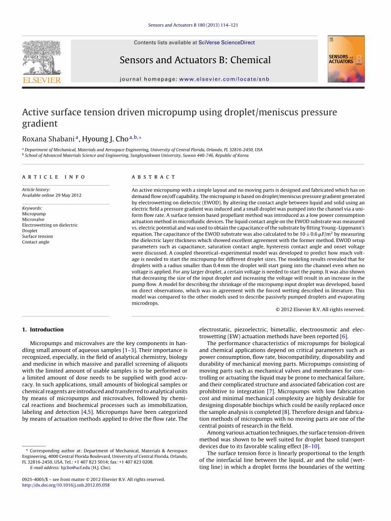
Fig. 1. Fabrication steps for the micropump. (a) Silicon wafer was used as the bot-tom electrode. Diluted PDMS was spin-coated to mask the defects. A SOG film wasformed as an insulating layer. (b) Diluted PDMS was spin-coated again to form a thinhydrophobic film. (c) A PDMS block was cast using a SU-8 mold to form microchan-nt(
ptachoh
2
tifflcaP(
cbt
force. The theoretical explanations behind this saturation are stillunder debate and not conclusive yet. Various explanations havebeen given, which try to find this phenomenon’s origination fromtrapping of electric charge, ionization of gas close to the liquid–solid
els. The liquid inlet, the air outlet and the drop formation hole were punched inhe PDMS block. The PDMS block with microchannels was bonded to the PDMS film.d) The interconnection and the electrical contacts were made.
otential [26]. The hydrophobic layer from this point of view putshe meniscus in a non-wetting state ready to be relaxed and actu-ted by applying the voltage. In order to reduce the total materialost and simplify the fabrication steps, instead of commonly usedydrophobic materials in EWOD such as CYTOP (Asahi Glass Co.),r Teflon AF (DuPont), a second PDMS film was formed as both theydrophobic and the bonding layer in our device (Fig. 1b).
.2. Soft lithography and bonding
A separate PDMS block was cast using a SU-8 mold and attachedo the EWOD substrate to form a microchannel. In addition to annlet and an outlet (an escape route for air), an orifice for dropletormation was punched into the PDMS block before bonding. Theully cured PDMS thin film which was formed as the hydrophobicayer in previous step was used as the bonding layer as well. Aorona discharge method [27] was used at room temperature andtmospheric pressure. A leak free bonding for fluids between theDMS film and the microchannel block was ensured before testingFig. 1c).
This method is in contrast with the other methods using partiallyured or uncured PDMS adhesive or a variation of cross linker foronding. This provides the uniformity of surface characteristic to allhe channel walls. It is worth mentioning that although the PDMS
uators B 180 (2013) 114– 121
thin film, initially becomes hydrophilic due to the corona dischargeprocess but this effect is not permanent and it eventually reverts tothe original hydrophobic state [28,29].
2.3. Microfluidic interconnections and electrical contacts
A metallic tube with a diameter of slightly larger than the size ofthe punched holes in the PDMS block was inserted into the liquidinlet. The PDMS is elastic and could easily hold the inserted tubein its place and make a leak free connection for fluid. A flexiblepolymer tube was connected to the steel tube (Fig. 1d). A stainlesssteel tube inserted in the inlet was used as the upper electrode(Fig. 1d). This ensures that electrical contact to the liquid is alwaysmaintained. The upper electrode was grounded and the voltage wasapplied to the conductive layer in the EWOD substrate.
3. Results and discussion
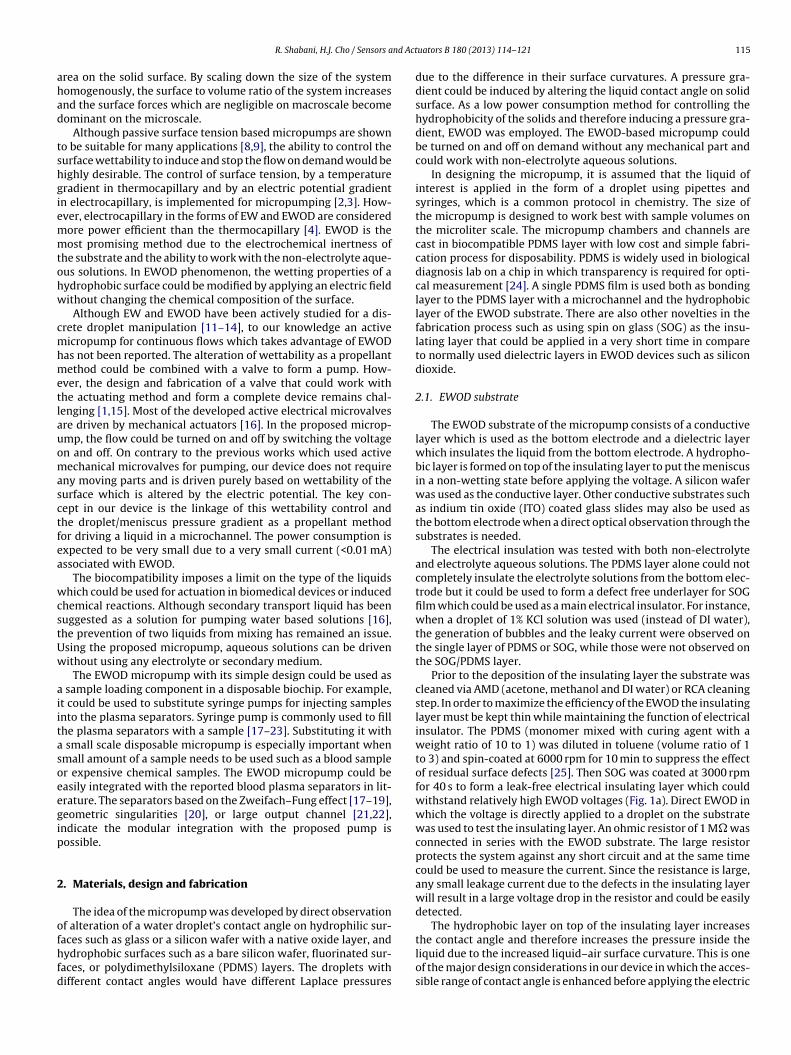
The EWOD substrate was characterized by studying the effectof the electric potential on the droplet contact angle. The appliedvoltage to the liquid was varied from 0 V to 120 V and the dropletcontact angle on the substrate was measured (Fig. 2). For volt-ages less than 34 V the contact angle is at its highest value, �max,and remains constant with an average value of 86◦. As the voltageincreases from 34 V the contact angle decreases. Finally for voltagesabove 90 V the contact angle saturates to its lowest value, �min, withan average value of 57◦. In terms of operation, any applied voltageabove 90 V only increases the risk of dielectric break-down.
A voltage of 100 V was selected (above 90 V and below 120 V) forthe micropump operation to make sure that the device is workingin the saturation region of the contact angle (Fig. 2). In other wordsincreasing the voltage further will not improve the pump operationsince the contact angle will not be reduced further. A working volt-age in the saturation region will guarantee that the contact angleis not sensitive to small voltage fluctuations of the device.
The observed plateau at higher voltages is associated with thesaturation of the contact angle which prevents the full wetting(zero contact angle) and limits the variation of the surface tension
Fig. 2. Droplet contact angle on EWOD substrate vs. voltage: the dash line is thetheoretical fit to the data. The hysteresis contact angle is shown as �max, the satura-tion contact angle is shown as �min, and the onset voltage is shown as Vonset. In theequation: A is a constant, c is the capacitance of the EWOD substrate and � is thesurface tension of water–air.
nd Actuators B 180 (2013) 114– 121 117
wr
lctsll
WosootaTmtdc
btst
cluct
�
w�tvSce
�
wt(tffrc1
aεtafmo1f
R. Shabani, H.J. Cho / Sensors a
etting line, wetting line instability, zero interfacial tension crite-ion and the droplet resistance [26,30].
On the other hand the constant value of the contact angle atower voltages (<34 V in Fig. 2) is related to the hysteresis of theontact angle or the pinning effect [30,31]. The pinning effect ishe tendency of the liquid to preserve its wetting or non-wettingtates on the solid surface. This effect plays an important role atower voltages in which EWOD is not strong enough to force theiquid to wet the hydrophobic surface.
The pinning effect tends to pin the wetting line to the surface.hen an external force (e.g. due to a pressure gradient) is exerted
n a wetting line, the pinning effect makes the wetting line on theurface stationary and as a result the contact angle is increasedr reduced without the movement of the wetting line dependingn the direction of the external force [32]. The EWOD effect tendso increase the wetted area (the contact area between the dropletnd the surface) and therefore tends to reduce the contact angle.he droplet volume is constant so an increase in the wetted areaeans a decrease in contact angle (Eq. (3)). However, the EWOD is
oo weak at lower voltages and it could not move the wetting lineue to the pinning effect and therefore the contact angle does nothange.
The application of silicone oil to the solid surface has proved toe effective in reducing the contact angle hysteresis and improvinghe liquid’s reaction to the change in electric potential in EWODetup. However such surface treatment is often not desirable dueo the oil residues and non-uniformity of its effect.
It is apparent that there is an onset voltage, Vonset, in which theontact angle starts a transition from a higher constant value to aower constant value. The transition region could be understoodsing Young–Lippmann’s equation [33,34] which states that theontact angle is a function of the applied voltage and the surfaceensions in an electrowetting setup:
= cos−1
((�sa − �ls + cV2/2)
�la
), (1)
here � is the liquid contact angle on the substrate, �sa, � ls andla are the substrate–air, liquid–substrate and liquid–air surface
ensions respectively in the absence of electric potential, V is theoltage and c is the capacitance (�F/m2) of the EWOD substrate.ince the surface tensions are constant in this experiment, and c isonstant for a specific setup, we could simplify Young–Lippmann’squation to:
(V) = cos−1(A + BV2), (2)
here A and B are two constants. This equation could be fit-ed to the experimental data using A and B as fitting parametersdash line shown in Fig. 2). A good agreement was found betweenhe electrowetting experimental data and the theoretical equationor voltages above 30 V and less than 90 V. The values obtainedor A and B for the best fit are −1.8 × 10⁻² and 7.2 × 10⁻⁵ (1/V2)espectively. Using the surface tension of water–air, 72 mN/m, theapacitance of the micropump EWOD substrate, c, is obtained to be0 ± 0.6 �F/m2.
The capacitance, c, and the thickness of the insulation layer, t,re related as c = (ε0εr)/t, where ε0 is the vacuum permittivity andr is the relative permittivity of the insulating layer. The dielec-ric layer in the fabricated micropump consists of a thin SOG layernd two PDMS films. The thickness of the SOG formed at 3000 rpmor 40 s is 0.2 �m. Considering the known values of relative per-
ittivity, εr, of SOG and PDMS (3.9 and 2.65) and the thicknessf PDMS film (1.1 �m) [25], the capacitance is calculated to be0 �F/m2 which is in excellent agreement with the result obtainedrom Young–Lippmann’s equation.
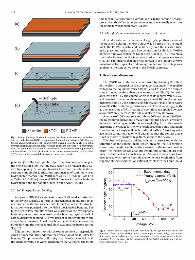
Fig. 3. The input droplet on top of the micropump is driven into the channel byapplying the voltage.
Young–Lippmann’s fit to the contact angle vs. voltage could beutilized to demonstrate the efficiency of EWOD setup and used ascomparative measure for evaluating the strength of EWOD in onedevice with that in other fabricated devices. For this purpose fourparameters associated with Fig. 2 are utilized: the saturation con-tact angle, �min, the hysteresis contact angle, �max, the capacitanceof the substrate, c, and the onset voltage, Vonset. EWOD setup, witha larger difference between the hysteresis contact angle and thesaturation contact angle, is more efficient and for a higher capac-itance, c, the switching from �max to �min occurs sharply and forless change in the applied voltage (Eqs. (1) and (2)). In addition, alower onset voltage means a lower working voltage for the device.This gives an insight into the design guideline for energy-efficientEWOD devices.
For priming, water was supplied in the channel to make contactwith the hydrophobic surface of the EWOD substrate at the bottomof the channel and to form a droplet as a positive pressure source ontop of the channel (Fig. 3). A liquid meniscus is also formed insidethe channel. The droplet and the meniscus contact angles are in anon-wetting state on the hydrophobic PDMS surface.
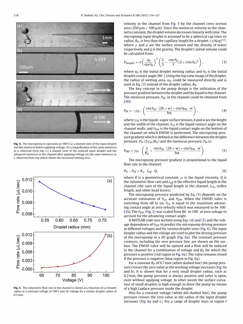
Prior to applying the voltage the droplet was stable and the liq-uid inside the channel was in the non-wetting state (Fig. 4a and b).Only, after applying the voltage (V = 100 V), the droplet starts flow-ing into the channel (Fig. 4c and d). The EWOD substrate which isin contact with the liquid, works similar to a capacitor. A fringingelectric field, which is formed at the substrate–liquid–air interface,helps the liquid to wet the surface and move forward in the channel.In other words the decrease in the contact angle at the bottom of thechannel reduces the liquid meniscus curvature inside the channeland produces a positive pumping pressure. The droplet/meniscuspressure gradient is activated and the droplet is pumped into thechannel with a uniform flow rate.
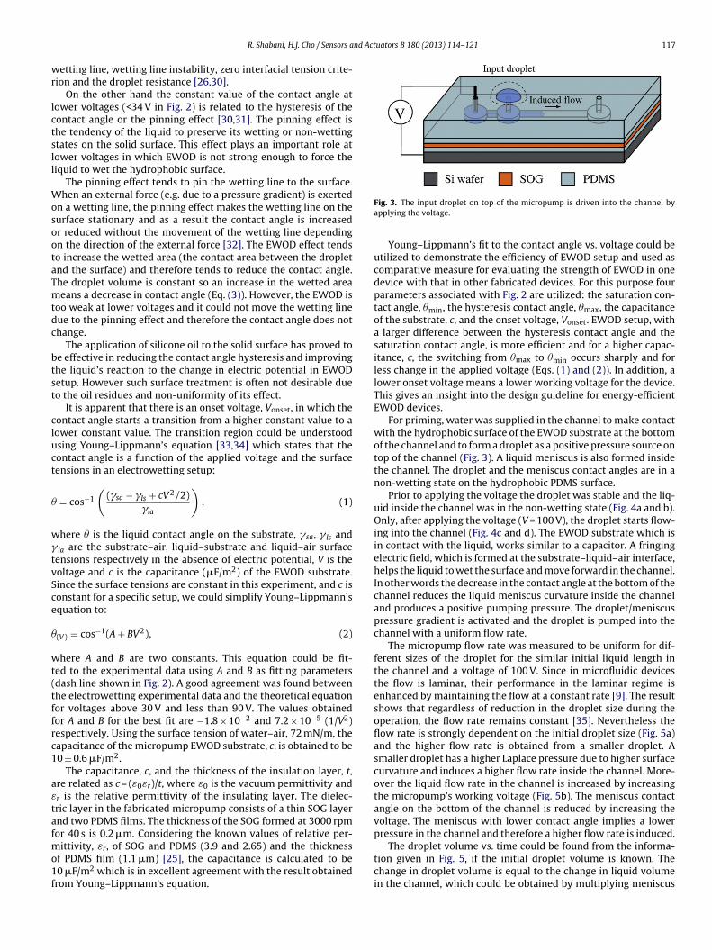
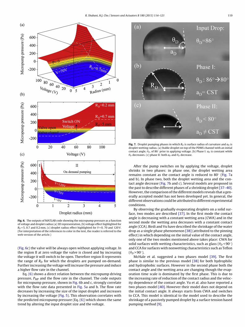
The micropump flow rate was measured to be uniform for dif-ferent sizes of the droplet for the similar initial liquid length inthe channel and a voltage of 100 V. Since in microfluidic devicesthe flow is laminar, their performance in the laminar regime isenhanced by maintaining the flow at a constant rate [9]. The resultshows that regardless of reduction in the droplet size during theoperation, the flow rate remains constant [35]. Nevertheless theflow rate is strongly dependent on the initial droplet size (Fig. 5a)and the higher flow rate is obtained from a smaller droplet. Asmaller droplet has a higher Laplace pressure due to higher surfacecurvature and induces a higher flow rate inside the channel. More-over the liquid flow rate in the channel is increased by increasingthe micropump’s working voltage (Fig. 5b). The meniscus contactangle on the bottom of the channel is reduced by increasing thevoltage. The meniscus with lower contact angle implies a lowerpressure in the channel and therefore a higher flow rate is induced.
The droplet volume vs. time could be found from the informa-tion given in Fig. 5, if the initial droplet volume is known. Thechange in droplet volume is equal to the change in liquid volumein the channel, which could be obtained by multiplying meniscus
118 R. Shabani, H.J. Cho / Sensors and Act
Fig. 4. The micropump in operation at 100 V (a) a slanted view of the input dropletand the meniscus before applying voltage, (b) a magnification of the same meniscusin a, observed from top, (c) a slanted view of the reduced input droplet and theadvanced meniscus in the channel after applying voltage (d) the same meniscus inc, observed from top which shows the increased wetting area.
Fig. 5. The volumetric flow rate in the channel is shown as a function of (a) dropletradius at a constant voltage of 100 V and (b) voltage for a similar droplet radius of0.5 mm.
uators B 180 (2013) 114– 121
velocity in the channel from Fig. 5 by the channel cross sectionarea (250 �m × 100 �m). Since the meniscus velocity in the chan-nel is constant, the droplet volume decreases linearly with time. Themicropump input droplet is assumed to be a spherical cap since itsradius, RD, is less than the capillary length for a droplet, (�/4�g)1/2,where � and � are the surface tension and the density of waterrespectively and g is the gravity. The droplet’s initial volume couldbe calculated from:
Vdroplet = �(
aD
sin �D
)3(
23
− cos �D
3(2 + (sin �D)2
), (3)
where aD is the initial droplet wetting radius and �D is the initialdroplet contact angle (86◦). Using the top view image of the droplet,the radius of wetting area, aD, could be measured directly and isused in Eq. (3) instead of the droplet radius, RD.
The key concept in the pump design is the utilization of thepressure gradient between the droplet and the liquid in the channel.The meniscus pressure, PM, in the channel could be obtained from[36]:
PM = −�VL ·(
cos �Ch · (2h + w) + cos �EW · w
hw
), (4)
where �VL is the liquid–vapor surface tension, h and w are the heightand the width of the channel, �Ch is the liquid contact angle on thechannel walls, and �EW is the liquid contact angle on the bottom ofthe channel on which EWOD is performed. The micropump pres-sure gradient which is defined as the difference between the dropletpressure, PD, (2�VL/RD) and the meniscus pressure, PM is:
PMP = �VL ·(
2RD
+ cos �Ch · (2h + w) + cos �EW · w
hw
)(5)
The micropump pressure gradient is proportional to the liquidflow rate in the channel:
PD − PM = K� · Leff · Q, (6)
where K is a geometrical constant, � is the liquid viscosity, Q isthe volumetric flow rate and Leff is the effective liquid length in thechannel (the sum of the liquid length in the channel, LCh, orificelength, and other head losses).
The micropump pressure predicted by Eq. (5) depends on theaccurate estimation of �Ch and �EW. When the EWOD valve isswitching from off to on, �Ch is equal to the maximum advanc-ing contact angle at zero velocity which was measured to be 100◦
[35]. The �EW (Fig. 2) was scaled from 86◦ to 100◦ at zero voltage toaccount for the advancing contact angle.
A MATLAB code was written using Eqs. (4) and (5) and the volt-age dependence of �EW to predict the micropump driving pressureat different voltages and for various droplet sizes (Fig. 6). The inputdroplet radius and the voltage are used to plot the driving pressureof the micropump in a 3D graph (Fig. 6a). The constant pressurecontours, including the zero pressure line, are shown on the sur-face. The EWOD valve will be opened and a flow will be inducedin the channel for a combination of voltage and RD for which thepressure is positive (red region in Fig. 6a). The valve remains closedif the pressure is negative (blue region in Fig. 6a).
For a constant RD of 0.7 mm (white dashed line) the pump pres-sure crosses the zero value as the working voltage increases (Fig. 6aand b). It is shown that for a very small droplet radius, such as0.2 mm, the pump pressure is always positive and valve is open,even without applying voltage. In other words the surface curva-ture of small droplets is high enough to drive the pump by means
of a high Laplace pressure inside the droplet.
Also for a constant voltage (white dot-dashed line), the pumppressure crosses the zero value as the radius of the input dropletincreases (Fig. 6a and c). For a range of droplet sizes in region I
R. Shabani, H.J. Cho / Sensors and Actuators B 180 (2013) 114– 121 119
Fig. 6. The outputs of MATLAB code showing the micropump pressure as a functionof voltage and droplet radius (a) 3D representation, (b) voltage effect highlighted forRD = 5, 0.7 and 0.2 mm, (c) droplet radius effect highlighted for V = 0, 70 and 120 V.(w
(tttFa
pfwdbtt
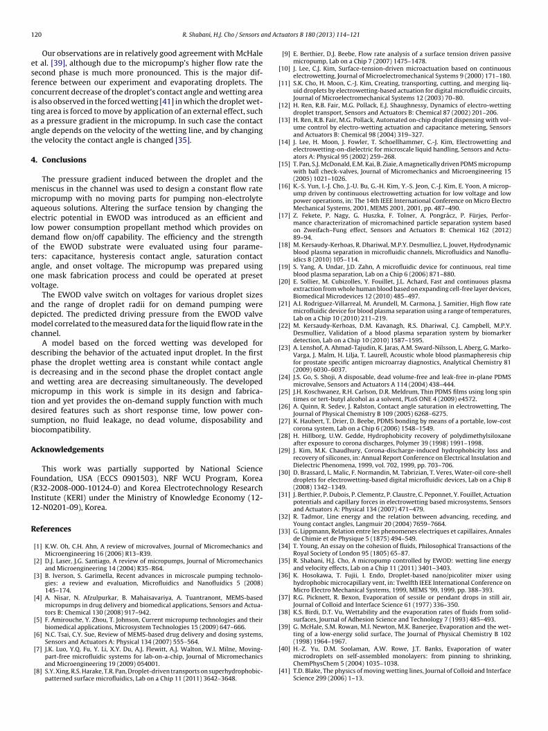
Fig. 7. Droplet pumping phases in which RD is surface radius of curvature and aD isdroplet wetting radius. (a) Stable droplet on top of the PDMS channel with an initial
the initial contact angle. It always starts from CWA and switches
For interpretation of the references to color in the text, the reader is referred to theeb version of the article.)
Fig. 6c) the valve will be always open without applying voltage. Inhe region II at zero voltage the valve is closed and by increasinghe voltage it will switch to be open. Therefore region II representshe range of RD for which the droplets are pumped on-demand.urther increasing the voltage will increase the pressure and induce
higher flow rate in the channel.Eq. (6) shows a direct relation between the micropump driving
ressure, PMP and the flow rate in the channel. The code outputsor micropump pressure, shown in Fig. 6b and c, strongly correlateith the flow rate data presented in Fig. 5a and b. The flow rateecreases by increasing the size of the input droplet and increases
y increasing the voltage (Fig. 5). This observation correlates withhe predicted micropump pressure (Eq. (6)) which shows the samerend by altering the input droplet size and the voltage.
contact angle, �D , of 86◦ prior to applying voltage. (b) Phase I: aD is constant while�D decreases. (c) phase II: both aD and �D decrease.
After the pump switches on by applying the voltage, dropletshrinks in two phases: in phase one, the droplet wetting arearemains constant as the contact angle is reduced to 80◦ (Fig. 7aand b). In phase two, both the droplet wetting area and the con-tact angle decrease (Fig. 7b and c). Several models are proposed inthe past to describe different phases of a shrinking droplet [37–40].However, the comparison of the different models reveals that a gen-erally accepted model has not been developed yet. In general, thedifferent observations could be attributed to different experimentalconditions.
By observing the gradually evaporating droplets on a solid sur-face, two modes are described [37]. In the first mode the contactangle is decreasing with a constant wetting area (CWA) and in thesecond mode the wetting area decreases with a constant contactangle (CCA). Birdi and Vu have described the shrinkage of the waterdrop as a single phase phenomenon [38] (attributed to the pinningeffect) in which depending on the initial value of the contact angle,only one of the two modes mentioned above takes place: CWA forsolid surfaces with wetting characteristics, such as glass (�D < 90◦)and CCA for surfaces with nonwetting characteristics such as Teflon(�D > 90◦).
McHale et al. suggested a two phases model [39]. The firstphase is similar to the previous model [38] for both hydrophilicand hydrophobic surfaces. However in the second phase both thecontact angle and the wetting area are changing though the evap-oration time scale is dominated by the first phase. This is due tothe increasing rate of reduction of the contact radius and the veloc-ity dependence of the contact angle. Yu et al. also have reported atwo phases model [40]. However their model does not depend on
to CCA. This model is identical to the model used to describe theshrinkage of a passively pumped droplet by a surface tension basedpumping method [9].
1 nd Act
esfcitaat
4
mmaeldotaov
admc
dpiamtdsb
A
F(I1
R
[
[
[
[
[
[
[
[
[
[
[
[
[
[
[
[
[
[
[
[
[
[
[
[
[
[
[
[
[
[
20 R. Shabani, H.J. Cho / Sensors a
Our observations are in relatively good agreement with McHalet al. [39], although due to the micropump’s higher flow rate theecond phase is much more pronounced. This is the major dif-erence between our experiment and evaporating droplets. Theoncurrent decrease of the droplet’s contact angle and wetting areas also observed in the forced wetting [41] in which the droplet wet-ing area is forced to move by application of an external effect, suchs a pressure gradient in the micropump. In such case the contactngle depends on the velocity of the wetting line, and by changinghe velocity the contact angle is changed [35].
. Conclusions
The pressure gradient induced between the droplet and theeniscus in the channel was used to design a constant flow rateicropump with no moving parts for pumping non-electrolyte
queous solutions. Altering the surface tension by changing thelectric potential in EWOD was introduced as an efficient andow power consumption propellant method which provides onemand flow on/off capability. The efficiency and the strengthf the EWOD substrate were evaluated using four parame-ers: capacitance, hysteresis contact angle, saturation contactngle, and onset voltage. The micropump was prepared usingne mask fabrication process and could be operated at presetoltage.
The EWOD valve switch on voltages for various droplet sizesnd the range of droplet radii for on demand pumping wereepicted. The predicted driving pressure from the EWOD valveodel correlated to the measured data for the liquid flow rate in the
hannel.A model based on the forced wetting was developed for
escribing the behavior of the actuated input droplet. In the firsthase the droplet wetting area is constant while contact angle
s decreasing and in the second phase the droplet contact anglend wetting area are decreasing simultaneously. The developedicropump in this work is simple in its design and fabrica-
ion and yet provides the on-demand supply function with muchesired features such as short response time, low power con-umption, no fluid leakage, no dead volume, disposability andiocompatibility.
cknowledgements
This work was partially supported by National Scienceoundation, USA (ECCS 0901503), NRF WCU Program, KoreaR32-2008-000-10124-0) and Korea Electrotechnology Researchnstitute (KERI) under the Ministry of Knowledge Economy (12-2-N0201-09), Korea.
eferences
[1] K.W. Oh, C.H. Ahn, A review of microvalves, Journal of Micromechanics andMicroengineering 16 (2006) R13–R39.
[2] D.J. Laser, J.G. Santiago, A review of micropumps, Journal of Micromechanicsand Microengineering 14 (2004) R35–R64.
[3] B. Iverson, S. Garimella, Recent advances in microscale pumping technolo-gies: a review and evaluation, Microfluidics and Nanofluidics 5 (2008)145–174.
[4] A. Nisar, N. Afzulpurkar, B. Mahaisavariya, A. Tuantranont, MEMS-basedmicropumps in drug delivery and biomedical applications, Sensors and Actua-tors B: Chemical 130 (2008) 917–942.
[5] F. Amirouche, Y. Zhou, T. Johnson, Current micropump technologies and theirbiomedical applications, Microsystem Technologies 15 (2009) 647–666.
[6] N.C. Tsai, C.Y. Sue, Review of MEMS-based drug delivery and dosing systems,Sensors and Actuators A: Physical 134 (2007) 555–564.
[7] J.K. Luo, Y.Q. Fu, Y. Li, X.Y. Du, A.J. Flewitt, A.J. Walton, W.I. Milne, Moving-part-free microfluidic systems for lab-on-a-chip, Journal of Micromechanicsand Microengineering 19 (2009) 054001.
[8] S.Y. Xing, R.S. Harake, T.R. Pan, Droplet-driven transports on superhydrophobic-patterned surface microfluidics, Lab on a Chip 11 (2011) 3642–3648.
[
[
uators B 180 (2013) 114– 121
[9] E. Berthier, D.J. Beebe, Flow rate analysis of a surface tension driven passivemicropump, Lab on a Chip 7 (2007) 1475–1478.
10] J. Lee, C.J. Kim, Surface-tension-driven microactuation based on continuouselectrowetting, Journal of Microelectromechanical Systems 9 (2000) 171–180.
11] S.K. Cho, H. Moon, C.-J. Kim, Creating, transporting, cutting, and merging liq-uid droplets by electrowetting-based actuation for digital microfluidic circuits,Journal of Microelectromechanical Systems 12 (2003) 70–80.
12] H. Ren, R.B. Fair, M.G. Pollack, E.J. Shaughnessy, Dynamics of electro-wettingdroplet transport, Sensors and Actuators B: Chemical 87 (2002) 201–206.
13] H. Ren, R.B. Fair, M.G. Pollack, Automated on-chip droplet dispensing with vol-ume control by electro-wetting actuation and capacitance metering, Sensorsand Actuators B: Chemical 98 (2004) 319–327.
14] J. Lee, H. Moon, J. Fowler, T. Schoellhammer, C.-J. Kim, Electrowetting andelectrowetting-on-dielectric for microscale liquid handling, Sensors and Actu-ators A: Physical 95 (2002) 259–268.
15] T. Pan, S.J. McDonald, E.M. Kai, B. Ziaie, A magnetically driven PDMS micropumpwith ball check-valves, Journal of Micromechanics and Microengineering 15(2005) 1021–1026.
16] K.-S. Yun, I.-J. Cho, J.-U. Bu, G.-H. Kim, Y.-S. Jeon, C.-J. Kim, E. Yoon, A microp-ump driven by continuous electrowetting actuation for low voltage and lowpower operations, in: The 14th IEEE International Conference on Micro ElectroMechanical Systems, 2001, MEMS 2001, 2001, pp. 487–490.
17] Z. Fekete, P. Nagy, G. Huszka, F. Tolner, A. Pongrácz, P. Fürjes, Perfor-mance characterization of micromachined particle separation system basedon Zweifach–Fung effect, Sensors and Actuators B: Chemical 162 (2012)89–94.
18] M. Kersaudy-Kerhoas, R. Dhariwal, M.P.Y. Desmulliez, L. Jouvet, Hydrodynamicblood plasma separation in microfluidic channels, Microfluidics and Nanoflu-idics 8 (2010) 105–114.
19] S. Yang, A. Undar, J.D. Zahn, A microfluidic device for continuous, real timeblood plasma separation, Lab on a Chip 6 (2006) 871–880.
20] E. Sollier, M. Cubizolles, Y. Fouillet, J.L. Achard, Fast and continuous plasmaextraction from whole human blood based on expanding cell-free layer devices,Biomedical Microdevices 12 (2010) 485–497.
21] A.I. Rodriguez-Villarreal, M. Arundell, M. Carmona, J. Samitier, High flow ratemicrofluidic device for blood plasma separation using a range of temperatures,Lab on a Chip 10 (2010) 211–219.
22] M. Kersaudy-Kerhoas, D.M. Kavanagh, R.S. Dhariwal, C.J. Campbell, M.P.Y.Desmulliez, Validation of a blood plasma separation system by biomarkerdetection, Lab on a Chip 10 (2010) 1587–1595.
23] A. Lenshof, A. Ahmad-Tajudin, K. Jaras, A.M. Sward-Nilsson, L. Aberg, G. Marko-Varga, J. Malm, H. Lilja, T. Laurell, Acoustic whole blood plasmapheresis chipfor prostate specific antigen microarray diagnostics, Analytical Chemistry 81(2009) 6030–6037.
24] J.S. Go, S. Shoji, A disposable, dead volume-free and leak-free in-plane PDMSmicrovalve, Sensors and Actuators A 114 (2004) 438–444.
25] J.H. Koschwanez, R.H. Carlson, D.R. Meldrum, Thin PDMS films using long spintimes or tert-butyl alcohol as a solvent, PLoS ONE 4 (2009) e4572.
26] A. Quinn, R. Sedev, J. Ralston, Contact angle saturation in electrowetting, TheJournal of Physical Chemistry B 109 (2005) 6268–6275.
27] K. Haubert, T. Drier, D. Beebe, PDMS bonding by means of a portable, low-costcorona system, Lab on a Chip 6 (2006) 1548–1549.
28] H. Hillborg, U.W. Gedde, Hydrophobicity recovery of polydimethylsiloxaneafter exposure to corona discharges, Polymer 39 (1998) 1991–1998.
29] J. Kim, M.K. Chaudhury, Corona-discharge-induced hydrophobicity loss andrecovery of silicones, in: Annual Report Conference on Electrical Insulation andDielectric Phenomena, 1999, vol. 702, 1999, pp. 703–706.
30] D. Brassard, L. Malic, F. Normandin, M. Tabrizian, T. Veres, Water-oil core-shelldroplets for electrowetting-based digital microfluidic devices, Lab on a Chip 8(2008) 1342–1349.
31] J. Berthier, P. Dubois, P. Clementz, P. Claustre, C. Peponnet, Y. Fouillet, Actuationpotentials and capillary forces in electrowetting based microsystems, Sensorsand Actuators A: Physical 134 (2007) 471–479.
32] R. Tadmor, Line energy and the relation between advancing, receding, andYoung contact angles, Langmuir 20 (2004) 7659–7664.
33] G. Lippmann, Relation entre les phenomenes electriques et capillaires, Annalesde Chimie et de Physique 5 (1875) 494–549.
34] T. Young, An essay on the cohesion of fluids, Philosophical Transactions of theRoyal Society of London 95 (1805) 65–87.
35] R. Shabani, H.J. Cho, A micropump controlled by EWOD: wetting line energyand velocity effects, Lab on a Chip 11 (2011) 3401–3403.
36] K. Hosokawa, T. Fujii, I. Endo, Droplet-based nano/picoliter mixer usinghydrophobic microcapillary vent, in: Twelfth IEEE International Conference onMicro Electro Mechanical Systems, 1999, MEMS ’99, 1999, pp. 388–393.
37] R.G. Picknett, R. Bexon, Evaporation of sessile or pendant drops in still air,Journal of Colloid and Interface Science 61 (1977) 336–350.
38] K.S. Birdi, D.T. Vu, Wettability and the evaporation rates of fluids from solid-surfaces, Journal of Adhesion Science and Technology 7 (1993) 485–493.
39] G. McHale, S.M. Rowan, M.I. Newton, M.K. Banerjee, Evaporation and the wet-ting of a low-energy solid surface, The Journal of Physical Chemistry B 102(1998) 1964–1967.
40] H.-Z. Yu, D.M. Soolaman, A.W. Rowe, J.T. Banks, Evaporation of watermicrodroplets on self-assembled monolayers: from pinning to shrinking,ChemPhysChem 5 (2004) 1035–1038.
41] T.D. Blake, The physics of moving wetting lines, Journal of Colloid and InterfaceScience 299 (2006) 1–13.
nd Act
B
RLeaioHs
BS in Materials Engineering from Seoul National University (Korea) in 1991 and1989, respectively. His current research interests include surface tension-driven
R. Shabani, H.J. Cho / Sensors a
iographies
oxana Shabani is working as a research assistant in the Nanofab and BioMEMSab in University of Central Florida. She is a Ph.D. student majoring in mechanicalngineering in the department of Mechanical, Materials and Aerospace Engineering
t UCF. She earned her B.Sc. in mechanical engineering from the University of Tehrann 2007. She is currently working on computational modeling and experimentationf the wetting line energy and velocity effects on liquid flow in microfluidic devices.er research interests include design and fabrication of droplet based microfluidic
ystems, and microfluidic transport using electrowetting on dielectric (EWOD).
uators B 180 (2013) 114– 121 121
Hyoung J. Cho is an associate professor in the Department of Mechanical, Materi-als and Aerospace Engineering at the University of Central Florida. He is currentlythe director of the NanoFab and BioMEMS Lab at the UCF. He earned his Ph.D. inElectrical Engineering from University of Cincinnati (USA) in 2002, and MS and
microfluidic components, nanoparticle-integrated gas sensors, and micromachinedelectrochemical sensors for ROS (reactive oxygen species) detection. He was a recip-ient of NSF CAREER award in 2004.