27th International Conference on Technology in Collegiate Mathematics 264 www.ictcm.com Sensors and Actuators March 07, 2015 Stephen Wilkerson The Army Research Laboratory, Aberdeen Proving Grounds and Frank Wattenberg, United States Military Academy, West Point Abstract In this paper we begin with a simple project that will empower stu- dents to help solve our energy problems. They will build a “smart” system for controlling temperature. This project can be used as a stand-alone project, as part of a competition to build the best temperature controlled environment, or as a model for other projects. In addition to the basic Arduino starter kit you will need a small lamp and computer fan (details are given further on). To further simplify the programming and wiring we break this project into 3 separate components giving the details how to wire and program each part. 1 Background In the past 10 years there has been an explosion of sensors, actuators and other output and storage devices available for small microprocessors like the Arduino and Raspberry Pi Micro-processors. In this paper we examine some mathemat- ical applications that can be used with a sensor and a motor. In particular, we will make use of the Arduino Micro-processor coupled with a temperature 1
Transcript
27th International Conference on Technology in Collegiate Mathematics
264www.ictcm.com
Sensors and ActuatorsMarch 07, 2015
Stephen WilkersonThe Army Research Laboratory,
Aberdeen Proving Groundsand
Frank Wattenberg,United States Military Academy,
West Point
Abstract
In this paper we begin with a simple project that will empower stu-dents to help solve our energy problems. They will build a “smart” systemfor controlling temperature. This project can be used as a stand-aloneproject, as part of a competition to build the best temperature controlledenvironment, or as a model for other projects. In addition to the basicArduino starter kit you will need a small lamp and computer fan (detailsare given further on). To further simplify the programming and wiringwe break this project into 3 separate components giving the details howto wire and program each part.
1 Background
In the past 10 years there has been an explosion of sensors, actuators and otheroutput and storage devices available for small microprocessors like the Arduinoand Raspberry Pi Micro-processors. In this paper we examine some mathemat-ical applications that can be used with a sensor and a motor. In particular,we will make use of the Arduino Micro-processor coupled with a temperature
27th International Conference on Technology in Collegiate Mathematics
265www.ictcm.com
(a) Micro (b) Uno R3 (c) Leonardo (d) Mega2560
Figure 1: Some Arduino microprocessor Examples
sensor that is slowly heated up with a small lamp in an experiment. In additionto using a temperature sensor we will use a small fan to control the temperatureof our sensor to within a specific range. This experiment has many applicationslike cooling of an enclosed area or regulating the temperature of a building, car,library, or a chemical process within specific ranges. Everything from car en-gines to coffee pots and toasters require specific operational ranges. In the pastthese devices were controlled using mechanical means. In the future, with theuse of microprocessors, sensors, motors, and actuators, these functions mightbe controlled to far tighter specifications, increasing efficiency and conservingenergy in many commonly used devices. Experiments like the one in this activ-ity will hopefully act as a catalyst, to unlock the imagination of new students,instructors and entrepreneurs. Many ideas previously thought difficult are nowachievable on a relatively small budget. Examples making use of small inex-pensive microprocessors can be found in small pilotless drones, 3D printers, cellphones, and global positioning systems. We begin our activity with an overviewof what will be needed to conduct a simple series of temperature control exper-iments.
There are two small sized micro processors that are dominating the worldof small scale innovation: the Raspberry Pi and a micro-controller known asArduino [1] [2]. Using these new microprocessors there seems to be no lim-its to the projects that can be devised. They range from simple gadgets forhome and hobby use to whole new technologies that include: flying drones,unmanned robotic systems, 3D-printers, workshop tools, alarm systems, gamesand many other helpful instruments. Many of these projects are open sourcewith a plethora of videos and other helpful tips readily available on the internetat no cost. This new era of do it yourself researchers and entrepreneurs has astrong educational background. For the experiment shown here we have chosenthe Arduino Uno that can be purchased for less than 15 dollars. Not surpris-ingly, there are a number of compatible Arduino processors like the Micro, TheUno, the Leonardo and the Mega; see Figure 1 a,b,c, and d respectively for thissuite of microprocessors devices.
The Arduino Micro is a micro-controller board based on the ATmega-32u4,developed in conjunction with Adafruit. It has 20 digital input/output pins(7 of which can be used as Pulse Width Modulation (PWM) outputs and 12as analog inputs), a 16 MHz crystal oscillator, a micro USB connection, an
27th International Conference on Technology in Collegiate Mathematics
266www.ictcm.com
In Circuit Serial Programming (ICSP) header, and a reset button. It has aform factor that enables it to be easily placed on a breadboard. The ArduinoUno is a micro-controller board based on the ATmega-3281. It has 14 digitalinput/output pins (6 of which can be used as PWM outputs), 6 analog inputs,a 16 MHz ceramic resonator, a USB connection, a power jack, an ICSP header,and a reset button [3]. The Arduino Leonardo is a micro-controller board basedon the ATmega-32u4. It has 20 digital input/output pins (7 of which can beused as PWM outputs and 12 as analog inputs), a 16 MHz crystal oscillator,a micro USB connection, a power jack, an ICSP header and a reset button. Itcontains everything needed to support the micro-controller; simply connect it toa computer with a USB cable or power it with a AC-to-DC adapter or batteryto get started . The Arduino Mega 2560 is a micro-controller board based onthe ATmega-2560. It has 54 digital input/output pins (of which 15 can be usedas PWM outputs), 16 analog inputs, 4UARTs (hardware serial ports), a 16MHz crystal oscillator, a USB connection, a power jack, an ICSP header anda reset button. Any of these boards can be used for the experiments we givehere. However, as project complexity increases so does the need for computingpower. A good example of this is the Mega and its derivative that are favoritesof the Do It Yourself (DYI) 3D-printing movement.
Not withstanding, there are also a number of shields that plug directly intothe Arduino mother-board that gives a direct interface to the micro processor(no wiring required) for a variety of sensors. In addition, there are also a largenumber of compatible sensor and output devices from Ada fruit, Sparkfun,Arduino and others. We give a couple of examples here for reference in AppendixA Table A1 with potential suppliers. This is only a small example of the manysensor devices that can be found from a number of vendors. No less importantare the many output devices that can also be interfaced with micro processors.Appendix A Table A2 provides a small subset of these for reference. Each ofthese devices usually come with an example or two complete with programmingcode that either extract data or make use of an output device. Once you getpast the wiring, programming, and an example or two the only thing left is thepotential applications and the mathematics that will be needed to make thishappen. In this paper we will examine the steps needed to take a simple sensorgather data, do an analysis, and then solve a problem.
2 What’s Required
Several things are needed for this experiment including the basic hardware,wiring and the software required to make the experiment work. In this firstsection we will examine specifically what is needed to make this all work, whereto get these items, and the approximate cost. We will also look at how bestto test the wiring connections and where to find help with problems. We willalso examine the software needed to make the experiment run and its prob-lems. Not all of these items are straight forward, but once mastered will enable
1High Performance, Low Power Atmel AVR 8-Bit micro-controller Family
27th International Conference on Technology in Collegiate Mathematics
267www.ictcm.com
Table 1: Required materials for this sketch, from top left to right, Uno R3,breadboard, Diode, Transistor, push-wires, lamp, humidity and temperaturesensor, battery pack, fan, sd card
students and instructors to explore the world from a new perspective of exper-imentation and discovery. Not surprisingly, the internet has a host of examplesand can provide help when stuck. For example, there are numerous Arduinoforums available where educators and experimentalists can exchange ideas andhelp one another over difficulties2. Information on specific projects, hardware,microcontrollers as well as education and teaching can all be found on line. Infact the Arduino and Raspberry Pi are some of the best supported products onthe market. Whole new industries and market places have arisen from this newrevolution in microprocessing.
2.1 Hardware
The following are the 10 basic items needed to conduct the experiment shown inthis write up. Some basic knowledge of the Arduino micro processor, wiring ofsmall non-complex circuits, searching the world wide web, and programming in”C” are assumed as a foundation for this project. However, you do not need to bean expert in these areas to conduct the experiment, but some basic knowledgewill make this experiment go smoothly. The basic components required arelisted below and shown above in Table 1. Item’s with a “*” next to them arepart of the Standard Arduino Projects Book kit3.
2http://forum.arduino.cc/.3Items “*” are in the standard kit: http://arduino.cc/en/Main/ArduinoStarterKit, or The
Inland UNO Breadboard Kit for approximately $15.00
27th International Conference on Technology in Collegiate Mathematics
268www.ictcm.com
• Arduino Uno R3*̂• Bread Board*̂• Diode*̂• Transistor*̂• Push pins*̂
• Battery*̂
• Printer cable*̂• Fan $3.00• Lamp $6.00• Light Bulb $5.00• Temperature and Barametric Pressure Sensor $15.00• Micro SD card $15.00(Optional)
These components are easy to find and many of the items required can befound at electronics stores like the Micro Center 4 or Frys5. However, all itemscan also be found on line at Arduino6, Adafruit7, Spark Fun8 and Amazon9 tomention only a few locations.
2.2 Wiring
Temperature and humidity sensor wiring: We start with our wring in-structions by wiring the sensor and the Arduino Uno together. There alreadyexists a wiring test that can be used to build a temperature recorder on adafruit’ssite10. We borrowed figure 9(from the adafruit site; footnote 6) as we will beusing the exact same wiring for the Temperature and Humidity sensor for ourexperiment. The Adafruit example uses the UNO a4 and a5 pins to connect tothe SCL and SDA pins on the HTU21D-F sensor respectively. A summary ofthe wiring is given in Appendix B.Fan wiring: Motor wiring is important when using an Arduino microprocessor.For starters, the Arduino board does not have enough power to run a fan witha larger motor. Furthermore, due to the potential for back current it is impor-tant to include a diode to prevent current from flowing back into the UNO anddamaging it. A basic project for motors can be found in the Arduino Projectsbook titled: ”Motorized Pinwheel” project number 09. We will wire our projectusing the same pins that were used in the project Motorized Pinwheel in theArduino UNO project workbook, but without the on off switch wired in. Wegive the diagram in figure 8 in Appendix C. Fortunately there is no conflict with
27th International Conference on Technology in Collegiate Mathematics
269www.ictcm.com
any of the pins required for the other components used in this experiment. TheArduino provides a variety of pin connections of various functions. These canbe reviewed in the specifications for the Arduino Uno from the Arduino website. A summary of the pins used to operate the fan (or a motor) are given inAppendix C.SD Card wiring: The SD card is optional and not required to complete theexperiments. We include it here for completeness. The card allows a student torun the experiment for a longer period of time and then to directly access the filewith the data without the need of cutting and pasting from the Arduino serialwindow. The data can then be read into MatLab, Mathematica, or MS Excelfor further analysis and plotting (See Mathematical section). We will show howthis is done in the mathematical section. Figure 9 shows the basic wiring ofthe SD card to the Arduino Uno with one small exception. For our experimentwe will use the 5V UNO bus to power the SD card reader. A summary of theconnections are give in Appendix D.
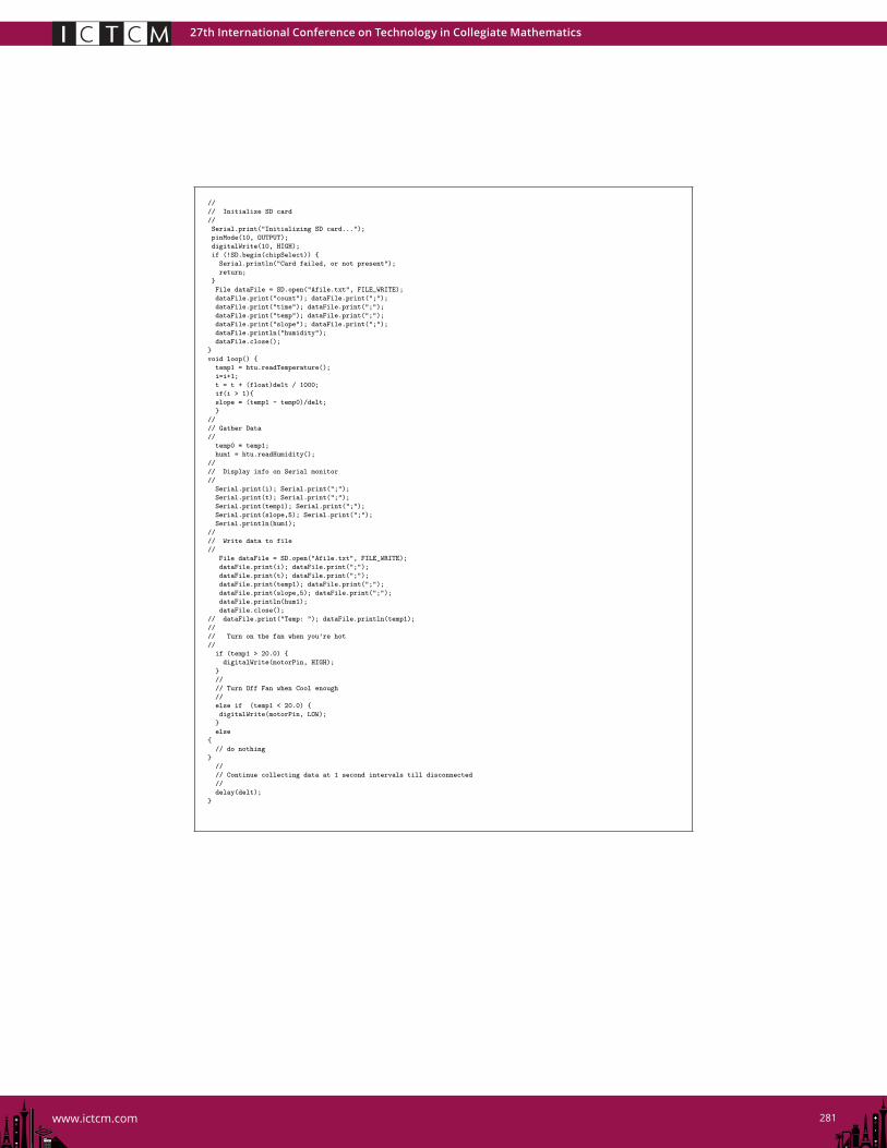
2.3 Computer Code
In order to make use of the HTU21D-F Humidity and Temperature sensor, theSD card reader and the fan we will need some basic libraries. In all, we willneed three libraries: (i.e. wire.h, adafruit HTU21DF.h and the SD.h libraries).To install these libraries on a specific system you will need to download themand then locate them on your computer. For simplicity I created a librariesfile under the Arduino directory and placed the files there. Then to load thoselibraries into your Arduino you will need to start up a Arduino sketch and usethe Arduino tab: Sketch>Import Library>Add Library and then add those toyour system one at a time. No, you do not have to do this every time you writea new program. Do this once and then they are loaded into your system andcan be accessed from any of your projects by simply including the correct codein the header file in your project program 11 12 13. All of the code used forthese initial Sketches can be found in Appendices. This sketch should work forany combination of sensors and actuators with the appropriate modifications forspecific sensor and motor changes and is not limited to these specific choices.
3 Experiment
Our experiment requires some subtle adjustments of the fan and lamp. If thelamp is too close, the small fan that we are using will be insufficient to moveenough air across the sensor to cool the sensor. On the other hand if the lampis too distant the sensor will not heat up enough to make the experiment work.Hence, an initial trial is needed to make the experiment work. With the program
27th International Conference on Technology in Collegiate Mathematics
270www.ictcm.com
loaded see what the ambient temperature is. Then turn on the lamp and makesure that the temperature increases. Once the ambient temperature in the roomis determined, the fan can be set to come on when the temperature increasesby a couple of a degrees Fahrenheit. Then turn on the fan (T >T0 + 3) tocool the circuit. Turn the fan back off when the temperature drops to a specificlevel (T <T0 + 2.9). Adjust the range of the light so that the temperatureoscillates between a high temperature and a lower temperature. This is thebasis of a temperature controlled process. There are many processes that canbe controlled using similar mathematics. Here we just look at some of the basicsfor a control system. Using simple experimentation the students can force thetemperature into a tightly controlled regime. However, this opens the door tosome really good mathematical discussions on how best to control a process.Sampling the data at 1 second intervals it can be seen that the heating andcooling is very rhythmic in nature from Figure 5. This is the outcome desiredso that further analysis is possible.
Figure 2: Experimental results at 1 second intervals
After the initial set up the adjustments required to get a good experiment inlamp position and fan location can be made while viewing the data on Arduino’sserial display. This can be accomplished by selecting Tools>Serial Monitor tabfrom the Arduino controls while in the Arduino programming environment. Theresults will be displayed as in Figure 6. Watching this screen one can adjustthe lamps distance to get the desired results. Once an acceptable arrangementis found, data can be recorded for further study.
4 Mathematics
This experiment provides a good example of how a process might heat up andcool off when being controlled by a heater and fan. Most processes that involveheat work on longer time scales. For example, it takes longer to heat up a car
27th International Conference on Technology in Collegiate Mathematics
271www.ictcm.com
Figure 3: Arduino serial display
(a) data ∆t = .1 (b) data ∆t = 1 (c) data ∆t = 2
Figure 4: Time increments, from left to right .1, 1 and 2 sec. respectively
engine and potentially much longer to cool it off. The simple solution in thisexperiment, if we were trying to control the process to a vary narrow range,we would be to simply turn on the fan as soon as the temperature rises abovea specific temperature and then turn it off again as soon as it drops belowthat same temperature. This is true due to the time frame and small scale ofour experiment and the ability to rapidly heat and cool our sensor with thesurrounding air. The way we got around this was to set a temperature rangethus providing some latency in our process thus making it more realistic of alarger process that we might be trying to control. This additional constraint forour experiment allows us to cycle the temperatures on a larger scale. Anotherpossibility is to change the sampling rate of the data. Different sampling ratesare shown in figure 7a,b,c.
A brief discussion of how this data might be moved onto a scientific platformlike MatLab or Mathematica is given here for completeness. In MatLab theimport function was used. The original coding was modified to write a csv fileby changing the write commands to the SD card. Of interest in controlling thisprocess is the rate of change of the temperature (slope) and potentially the areaunder the curve:
27th International Conference on Technology in Collegiate Mathematics
272www.ictcm.com
slope =Ti+1 − Ti
∆t
area =n∑
i=1
Ti∆t
In the first case, the rate of change can be used as a measure of when exactlyto turn on and off the cooling. In the latter, the area under the curve relates tothe energy being used. In order to control these processes better two approachescan be taken. One would involve the controlling of the fan speed to force thesystem into tighter tolerances while the second might consider the timing ofthe fan’s use. In the first case, the fan’s speed could be tied to a proportionalconstant Kp dependent on the temperature feedback, while a similar constantKd could be multiplied against the rate of change in the temperature, hencegiving the system a proportional derivative PD control system. The processshown in this experiment is governed by Newton’s law of cooling [4]:
dT
dt= −k(T − Ts)
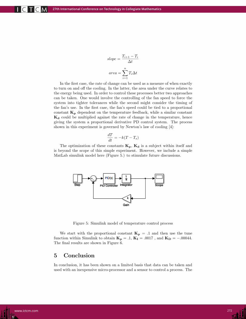
The optimization of these constants Kp, Kd is a subject within itself andis beyond the scope of this simple experiment. However, we include a simpleMatLab simulink model here (Figure 5.) to stimulate future discussions.
Figure 5: Simulink model of temperature control process
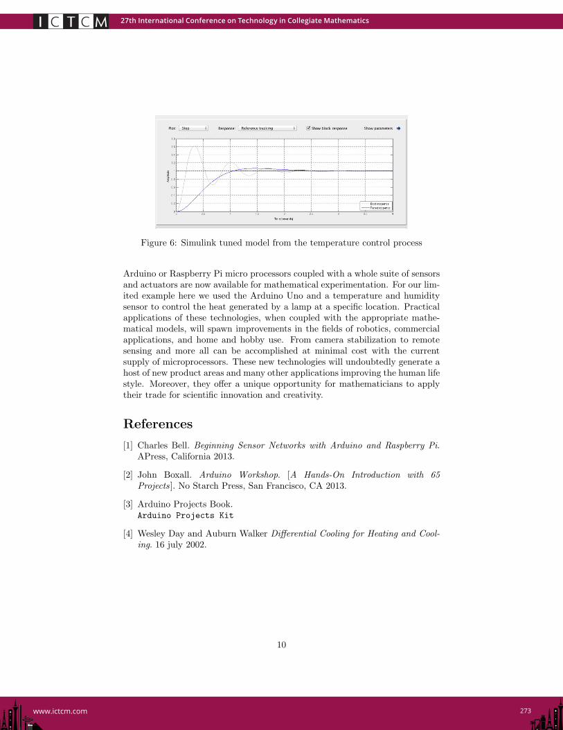
We start with the proportional constant Kp = .1 and then use the tunefunction within Simulink to obtain Kp = .1, KI = .0017 , and KD = −.00044.The final results are shown in Figure 6.
5 Conclusion
In conclusion, it has been shown on a limited basis that data can be taken andused with an inexpensive micro-processor and a sensor to control a process. The
27th International Conference on Technology in Collegiate Mathematics
273www.ictcm.com
Figure 6: Simulink tuned model from the temperature control process
Arduino or Raspberry Pi micro processors coupled with a whole suite of sensorsand actuators are now available for mathematical experimentation. For our lim-ited example here we used the Arduino Uno and a temperature and humiditysensor to control the heat generated by a lamp at a specific location. Practicalapplications of these technologies, when coupled with the appropriate mathe-matical models, will spawn improvements in the fields of robotics, commercialapplications, and home and hobby use. From camera stabilization to remotesensing and more all can be accomplished at minimal cost with the currentsupply of microprocessors. These new technologies will undoubtedly generate ahost of new product areas and many other applications improving the human lifestyle. Moreover, they offer a unique opportunity for mathematicians to applytheir trade for scientific innovation and creativity.
References
[1] Charles Bell. Beginning Sensor Networks with Arduino and Raspberry Pi.APress, California 2013.
[2] John Boxall. Arduino Workshop. [A Hands-On Introduction with 65Projects ]. No Starch Press, San Francisco, CA 2013.
[3] Arduino Projects Book.Arduino Projects Kit
[4] Wesley Day and Auburn Walker Differential Cooling for Heating and Cool-ing. 16 july 2002.
27th International Conference on Technology in Collegiate Mathematics
276www.ictcm.com
APPENDIX B
Humidity and Temperature Sensor
Figure 7: Wiring Diagram for HTU21-D Humidity and Temperature sensor
• HTU21D-F Sensor VIN to the UNO 5V.• HTU21D-F Sensor GND to the UNO GND.• HTU21D-F Sensor SCL to the UNO A5 pin.• HTU21D-F Sensor SDA to the UNO A4 pin.
27th International Conference on Technology in Collegiate Mathematics
278www.ictcm.com
APPENDIX C
Fan Wiring
Figure 8: Diagram enabling the fan to be activated using Arduino pin 9
• External positive voltage source to bread board positive.• External negative voltage source to bread board negative.• Transistor pin 1 to the UNO pin 9 See Figure 2.• Common ground both sides of bread board and Transistor middlepin.
• Fan wired between transistor pin 3 and Positive battery source.Diode between to prevent back flow (See Figure 2).
// No Libraries Required
// Set up constants
const int motorPin = 9; // the number of the motor pin
27th International Conference on Technology in Collegiate Mathematics
279www.ictcm.com
APPENDIX D
SD Card Wiring
Figure 9: Diagram enablingThe Sd card to be incorporated into the project.
• SD Card MOSI pin to Arduion Uno pin 11.• SD Card MISO pin to Arduion Uno pin 12.• SD Card CLK or SCK pin to Arduion Uno pin 13.• SD Card CS pin to Arduion Uno pin 10. . . .