24
Series 30 i /31 i /32 i - MODEL B Precise, fast and reliable www.fanucfa.com 888-FANUC-US (888-326-8287)
Series 30i /31i /32i - MODEL B
Precise, fast and reliable
www.fanucfa.com
888-FANUC-US (888-326-8287)
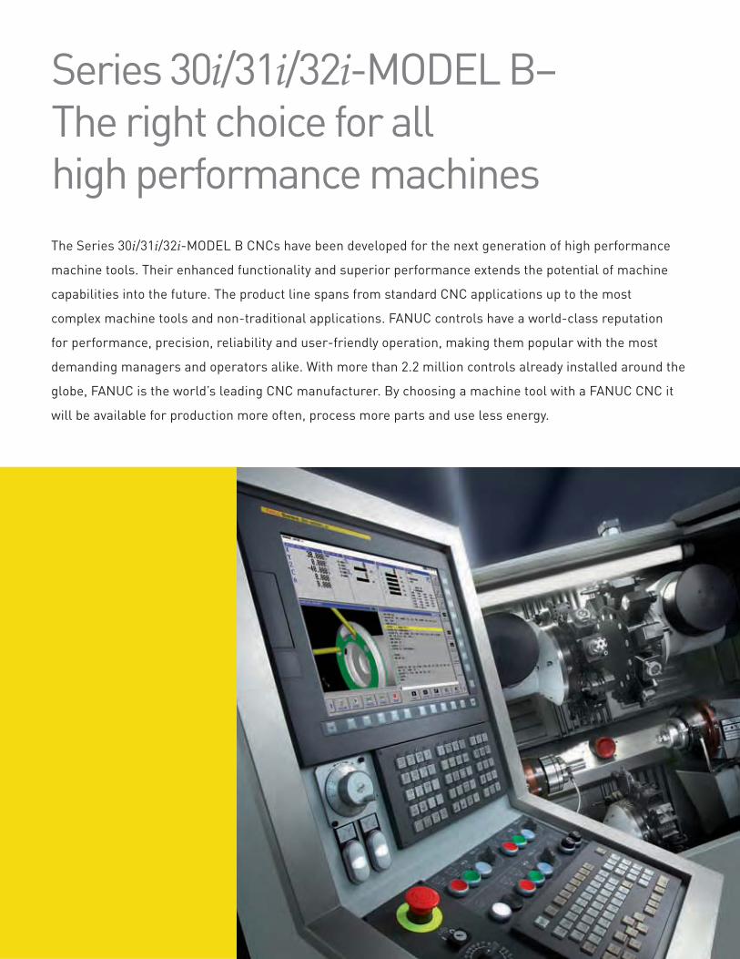
Series 30i/31i/32i-MODEL B– The right choice for all high performance machines
The Series 30i/31i/32i-MODEL B CNCs have been developed for the next generation of high performance
machine tools. Their enhanced functionality and superior performance extends the potential of machine
capabilities into the future. The product line spans from standard CNC applications up to the most
complex machine tools and non-traditional applications. FANUC controls have a world-class reputation
for performance, precision, reliability and user-friendly operation, making them popular with the most
demanding managers and operators alike. With more than 2.2 million controls already installed around the
globe, FANUC is the world’s leading CNC manufacturer. By choosing a machine tool with a FANUC CNC it
will be available for production more often, process more parts and use less energy.
Ultra-high-speed processors provide fast interpolation times with up
to 1000-block look-ahead, up to 10 paths and 40 axes and up to 24 axes
simultaneously. Up to 5 independent, 9.1 nanosecond-per-step PMC ladders
execute simultaneously, supporting up to 4096 digital inputs and outputs.
Unique solutions may be realized using powerful programming languages, user
interface development tools, real-time macros and PC functionality.
Series 30i/31i/32i-MODEL B CNCs may connect with Windows compatible PCs,
or rugged, diskless Windows CE.NET operator interfaces.
The CNC and drive system executes at a nanometer resolution all the way down
to the 16-million count encoders for the maximum precision and the smoothest
contoured surface finish quality.
Advanced software algorithms analyze part geometries and machine capabilities
and adjust trajectories and feedrates to provide the smoothest tool paths for the
highest processing speed at the specified precision.
Available on the world’s leading performance machine tools including 5-axis
machining centers, multi-axis lathes, mill-turn machines, transfer machines,
gear cutting machines, precision grinders, woodworking machines and state-of-
the-art, non-traditional applications.
Operators with previous FANUC experience can use their existing skills as they
learn new techniques, and existing part programs will run smoothly without
modification.
Reliable hardware with clear diagnostics provides a stable platform for
maximum machine availability. Additionally, factory-trained field service
engineers provide free lifetime over-the-phone technical support and local on-
site service increasing machine uptime.
Ethernet connectivity for high-speed part program transfers of large part
programs and data collection is standard.
Simulation of CNC operation, part programming and maintenance screens for
effective training of operators, part programmers, maintenance engineers and
technicians in a safe environment.
State-of-the-art hardware
Customer specific solutions
Ultimate resolution and precision
for quality machining
High-speed machining for quality and
reduced cycle times
Available on the world‘s best-in-class
machine tools
Simple operation for maximum
productivity
High reliability, easy maintenance and
world-class service and support
Connectivity for today‘s high-tech
manufacturing
Powerful simulation tools
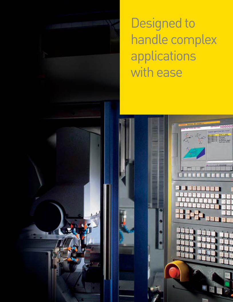
Designed to handle complex applications with ease
5-axis machining with Series 30i-MODEL B and Series
31i-MODEL B5, for precision parts that faithfully match the
original CAD drawing, with faster cycle times, improved
surfaces finishes and simplified part programming, setup
and operation.
Mill-turn machining, combining turning and milling in a
single part program to reduce setup and cycle time and
improve quality.
Linear and rotary transfer machining for the shortest
cycle times for high volume manufacturing with the
convenience and simplicity of a single CNC interface for
multiple spindles and stations.
Gear cutting, synchronizing multiple axes and spindles
and providing highly customized operator interfaces
for high quality cylindrical and bevel gear machining
technologies.
Precision grinding, with the performance and accuracy for
cylindrical and profile grinding.
Woodworking machining of large nested part programs
at ultra-high speed while maintaining accuracy for flat-
bed and 5-axis routers.
Nontraditional machining such as tape laying for
composite structures and airframe riveting.
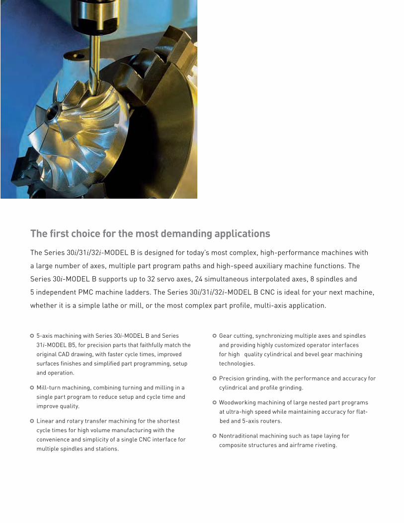
The first choice for the most demanding applicationsThe Series 30i/31i/32i-MODEL B is designed for today’s most complex, high-performance machines with
a large number of axes, multiple part program paths and high-speed auxiliary machine functions. The
Series 30i-MODEL B supports up to 32 servo axes, 24 simultaneous interpolated axes, 8 spindles and
5 independent PMC machine ladders. The Series 30i/31i/32i-MODEL B CNC is ideal for your next machine,
whether it is a simple lathe or mill, or the most complex part profile, multi-axis application.
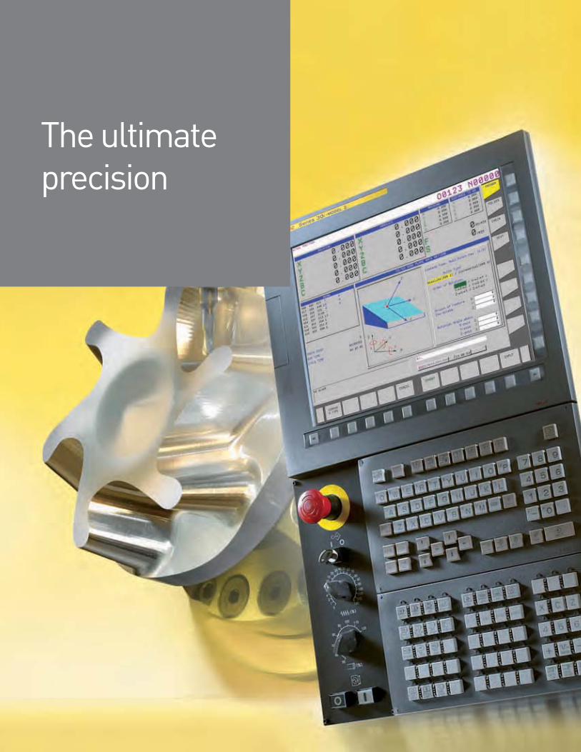
The ultimateprecision
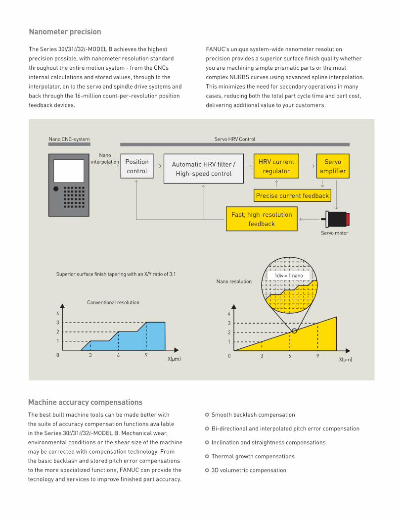
Nano CNC-system
Position
controlAutomatic HRV filter /
High-speed control
HRV current
regulator
Servo
amplifier
Precise current feedback
Fast, high-resolution
feedback
Servo HRV Control
Servo motor
Nano
interpolation
Nano resolution
Conventional resolution
Superior surface finish tapering with an X/Y ratio of 3:1
X(μm)9630
1
2
3
4
X(μm)9630
1
2
3
4
1div = 1 nano
The Series 30i/31i/32i-MODEL B achieves the highest
precision possible, with nanometer resolution standard
throughout the entire motion system - from the CNCs
internal calculations and stored values, through to the
interpolator, on to the servo and spindle drive systems and
back through the 16-million count-per-revolution position
feedback devices.
FANUC’s unique system-wide nanometer resolution
precision provides a superior surface finish quality whether
you are machining simple prismatic parts or the most
complex NURBS curves using advanced spline interpolation.
This minimizes the need for secondary operations in many
cases, reducing both the total part cycle time and part cost,
delivering additional value to your customers.
Nanometer precision
The best built machine tools can be made better with
the suite of accuracy compensation functions available
in the Series 30i/31i/32i-MODEL B. Mechanical wear,
environmental conditions or the shear size of the machine
may be corrected with compensation technology. From
the basic backlash and stored pitch error compensations
to the more specialized functions, FANUC can provide the
tecnology and services to improve finished part accuracy.
Smooth backlash compensation
Bi-directional and interpolated pitch error compensation
Inclination and straightness compensations
Thermal growth compensations
3D volumetric compensation
Machine accuracy compensations
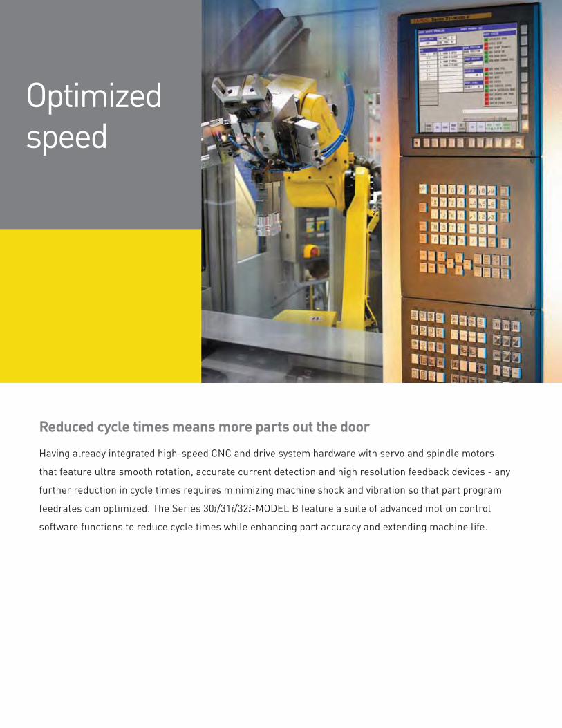
Reduced cycle times means more parts out the doorHaving already integrated high-speed CNC and drive system hardware with servo and spindle motors
that feature ultra smooth rotation, accurate current detection and high resolution feedback devices - any
further reduction in cycle times requires minimizing machine shock and vibration so that part program
feedrates can optimized. The Series 30i/31i/32i-MODEL B feature a suite of advanced motion control
software functions to reduce cycle times while enhancing part accuracy and extending machine life.
Optimized speed
Bell-shaped acc/decBell shaped acc/dec minimizes machine shock and reduces
the time it takes to accelerate and decelerate and can be
applied to rapid, contouring and tapping motions.
AI Contour Control AI Contour Control looks ahead in the part program to
eliminate the acc/dec and servo delays that limit feedrates
when cutting short line segments or contours, and effectively
eliminates machining trajectory error in corners and small
radii.
Nano smoothingNano smoothing converts CAM-generated line segments into
NURBS curves for faster execution and a superior surface
finish - without the need for drastic modifications to the CAM
system or existing part programs.
Faster positioningWhen transitioning between positioning and contouring
modes, a pause is often necessary to ensure path and part
accuracy. These pauses can be eliminated with intelligent part
programming, reducing the cycle time of parts with a lot of
positioning moves by up to 10%. The speed of a sequence
of p ositioning m oves is i ncreased b y p rogramming a radius
at the intersecting corner, minimizing the acceleration and
deceleration of each axis. A safe tool path that avoids inter-
ference areas is specified and speeds up common operations
such as moving to the tool change position.
Jerk controlIn part program sections in which acceleration changes
significantly, such as where the cutting path changes from a
straight line to curve, machine vibration or shock may occur.
Speed control and a change of acceleration suppress vibration
and machine shock and their associated machining errors.
HRVAuto-following HRV servo and spindle drive filters dynamically
suppresses mechanical resonance even when the frequency
changes.
Arbitrary speed threadingSpindle speed o verride can be activated during threading
to allow the operator to adjust the spindle speed to avoid
chatter, the CNC maintains feed axis synchronization to
assure thread definition. M-code activation ensures existing
part programs work as expected.
Previously machined threads can be repaired by manually
placing the tool into the machined thread with the spindle
stopped and registering the position with the CNC. After re-
tracting the tool, the thread can be re-machined easily.
Arbitrary s peed t hreading i s especially u seful for threading
large diameter or long length work-pieces a s used in the oil
and gas industries.
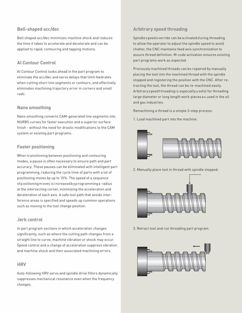
Remachining a thread is a simple 3-step process:
1. Load machined part into the machine.
2. Manually place tool in thread with spindle stopped.
3. Retract tool and run threading part program.
Operational and programming consistency are critical to
maximize the productivity of new equipment. Operators
that already have experience with FANUC controls will
be comfortable with the Series 30i/31i/32i-MODEL B in no
time at all, without the need for expensive retraining. CNC
enhancements can be adopted over time, either by learning
on the CNC or by using FANUC’s realistic and efficient
NCGuide CNC simulator.
Existing part programs will run smoothly on the new
control with little or no modification. Machine setup is
simplified with features like the Workpiece Setting Error
screen, adjusting the part program to the orientation
of the part on the machine table with easy to measure
an X/Y/Z and row-pitch-yaw values. Each operator can
select their preferred language quickly from any of the 18
supported, enhancing their comfort level and operational
effectiveness.
User-friendly operation and programming
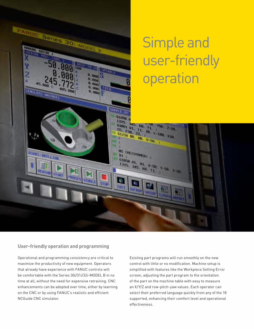
Simple and user-friendly operation
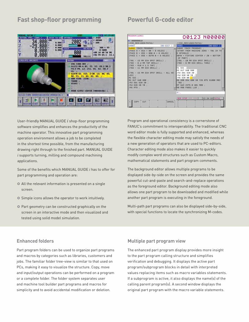
Program and operational consistency is a cornerstone of
FANUC’s commitment to interoperability. The traditional CNC
word editor mode is fully supported and enhanced, whereas
the flexible character editing mode may satisfy the needs of
a new generation of operators that are used to PC-editors.
Character editing mode also makes it easier to quickly
modify complex word structures such as Custom Macro,
mathematical statements and part program comments.
The background editor allows multiple programs to be
displayed side-by-side on the screen and provides the same
powerful cut-and-paste and search-and-replace operations
as the foreground editor. Background editing mode also
allows one part program to be downloaded and modified while
another part program is executing in the foreground.
Multi-path part programs can also be displayed side-by-side,
with special functions to locate the synchronizing M-codes.
Fast shop-floor programming Powerful G-code editor
User-friendly MANUAL GUIDE i shop-floor programming
software simplifies and enhances the productivity of the
machine operator. This innovative part programming
operation environment allows a job to be completed
in the shortest time possible, from the manufacturing
drawing right through to the finished part. MANUAL GUIDE
i supports turning, milling and compound machining
applications.
Some of the benefits which MANUAL GUIDE i has to offer for
part programming and operation are:
All the relevant information is presented on a single
screen.
Simple icons allows the operator to work intuitively.
Part geometry can be constructed graphically on the
screen in an interactive mode and then visualized and
tested using solid model simulation.
Enhanced foldersPart program folders can be used to organize part programs
and macros by categories such as libraries, customers and
jobs. The familiar folder tree-view is similar to that used on
PCs, making it easy to visualize the structure. Copy, move
and input/output operations can be performed on a program
or a complete folder. The folder system separates user
and machine tool builder part programs and macros for
simplicity and to avoid accidental modification or deletion.
Multiple part program viewThe enhanced part program display provides more insight
to the part program calling structure and simplifies
verification and debugging. It displays the active part
program/subprogram blocks in detail with interpreted
values replacing items such as macro variables statements.
If a subprogram is active, it also displays the name(s) of the
calling parent program(s). A second window displays the
original part program with the macro variable statements.
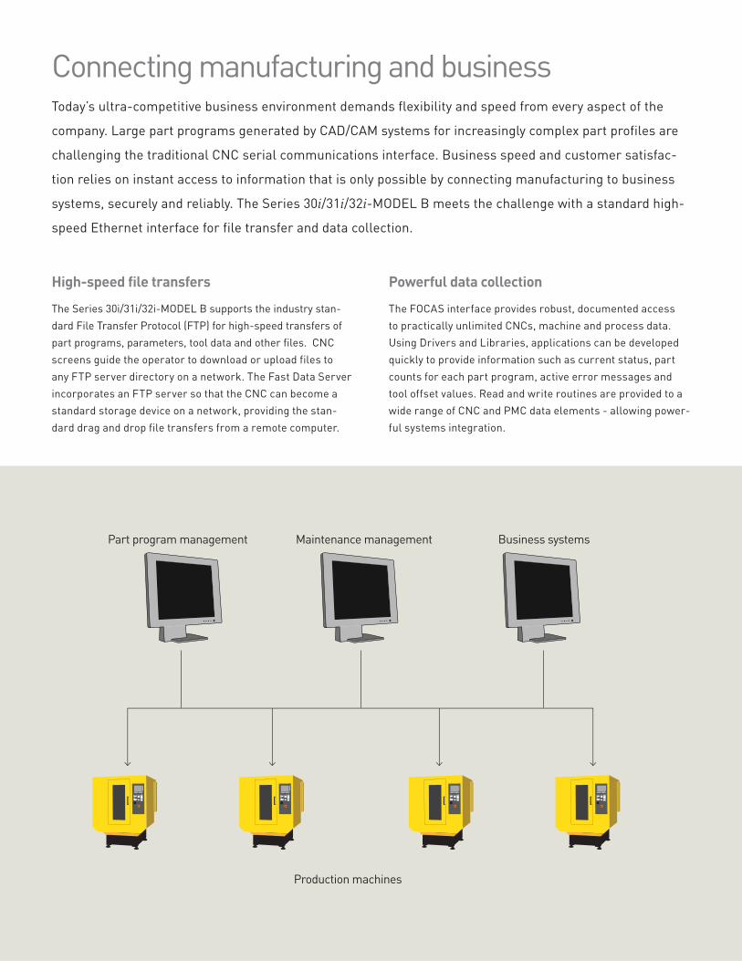
Part program management
Production machines
Maintenance management Business systems
Connecting manufacturing and businessToday’s ultra-competitive business environment demands flexibility and speed from every aspect of the
company. Large part programs generated by CAD/CAM systems for increasingly complex part profiles are
challenging the traditional CNC serial communications interface. Business speed and customer satisfac-
tion relies on instant access to information that is only possible by connecting manufacturing to business
systems, securely and reliably. The Series 30i/31i/32i-MODEL B meets the challenge with a standard high-
speed Ethernet interface for file transfer and data collection.
High-speed file transfersThe Series 30i/31i/32i-MODEL B supports the industry stan-
dard File Transfer Protocol (FTP) for high-speed transfers of
part programs, parameters, tool data and other files. CNC
screens guide the operator to download or upload files to
any FTP server directory on a network. The Fast Data Server
incorporates an FTP server so that the CNC can become a
standard storage device on a network, providing the stan-
dard drag and drop file transfers from a remote computer.
Powerful data collectionThe FOCAS interface provides robust, documented access
to practically unlimited CNCs, machine and process data.
Using Drivers and Libraries, applications can be developed
quickly to provide information such as current status, part
counts for each part program, active error messages and
tool offset values. Read and write routines are provided to a
wide range of CNC and PMC data elements - allowing power-
ful systems integration.
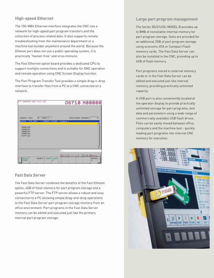
High-speed EthernetThe 100-MBit Ethernet interface integrates the CNC into a
network for high-speed part program transfers and the
collection of process related data. It also supports remote
troubleshooting from the maintenance department or a
machine tool builder anywhere around the world. Because the
Ethenet port does not use a public operating system, it is
practically “hacker-free” and virus immune.
The Fast Ethernet option board provides a dedicated CPU to
support multiple connections and is suitable for DNC operation
and remote operation using CNC Screen Display function.
The Part Program Transfer Tool provides a simple drag-n-drop
interface to transfer files from a PC to a CNC connected on a
network.
Large part program managementThe Series 30i/31i/32i-MODEL B provides up
to 8MB of nonvolatile internal memory for
part program storage. Slots are provided for
an additional 2GB of part program storage
using economic ATA or Compact Flash
memory cards. The Fast Data Server can
also be installed in the CNC, providing up to
4GB of flash memory.
Part programs stored in external memory
cards or in the Fast Data Server can be
edited and executed just like internal
memory, providing practically unlimited
capacity.
A USB port is also conveniently located at
the operator display to provide practically
unlimited storage for part programs, tool
data and parameters using a wide range of
commercially available USB flash drives.
Files can be easily moved between office,
computers and the machine tool - quickly
loading part programs into internal CNC
memory for execution.
Fast Data ServerThe Fast Data Server combines the benefits of the Fast Ethenet
option, 4GB of flash memory for part program storage and a
powerful FTP server. The FTP server allows a robust and easy
connection to a PC allowing simple drag-and-drop operations
to the Fast Data Server part program storage memory from an
office environment. Part programs in the Fast Data Server
memory can be edited and executed just like the primary
internal part program storage.
Unmatched reliabilityDowntime on your CNC machine is very expensive, especially
when you add up the cost of repairs, the lost production
capacity, and the potential revenue and goodwill lost if you
miss customers’ deliveries. FANUC’s continuous improve-
ment culture ensures that our CNC systems are the most
reliable available. Statistically, a hardware fault occurs only
once for every 15 years of productive service.
With the commitment of a 25-year parts availability guara-
tee, convenient local parts inventories and economical repair
and return services, you can look forward to decades of
trouble-free operation with the confidence that your
machines will be available for production when you need it.
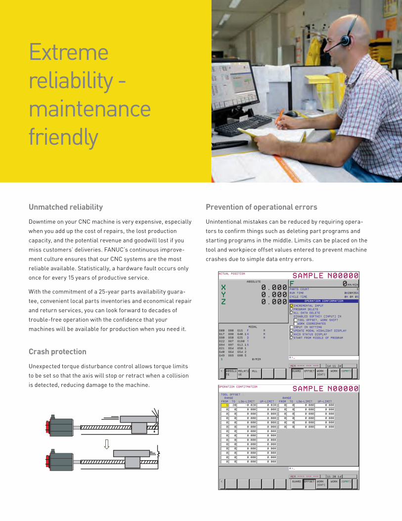
Crash protection Unexpected torque disturbance control allows torque limits
to be set so that the axis will stop or retract when a collision
is detected, reducing damage to the machine.
Extreme reliability - maintenance friendly
Prevention of operational errors Unintentional mistakes can be reduced by requiring opera-
tors to confirm things such as deleting part programs and
starting programs in the middle. Limits can be placed on the
tool and workpiece offset values entered to prevent machine
crashes due to simple data entry errors.
Maintenance friendly Batteries and fans are modularized for quick and easy
replacement without tools. An available rechargeable
backup unit eliminates the need to maintain the batteries. A
comprehensive package of maintenance tools is integrated
into the CNC to help keep your machine running and making
parts. A snapshot of any CNC screen can be captured to a
memory card to be used in troubleshooting. Troubleshooting
Guidance screens lead maintenance technicians easily
through recommended procedures to identify the root cause
of problems. Factory-trained field service engineers are
always available to provide you with free over-the-phone
technical support and local on-site service whenever you
need it.
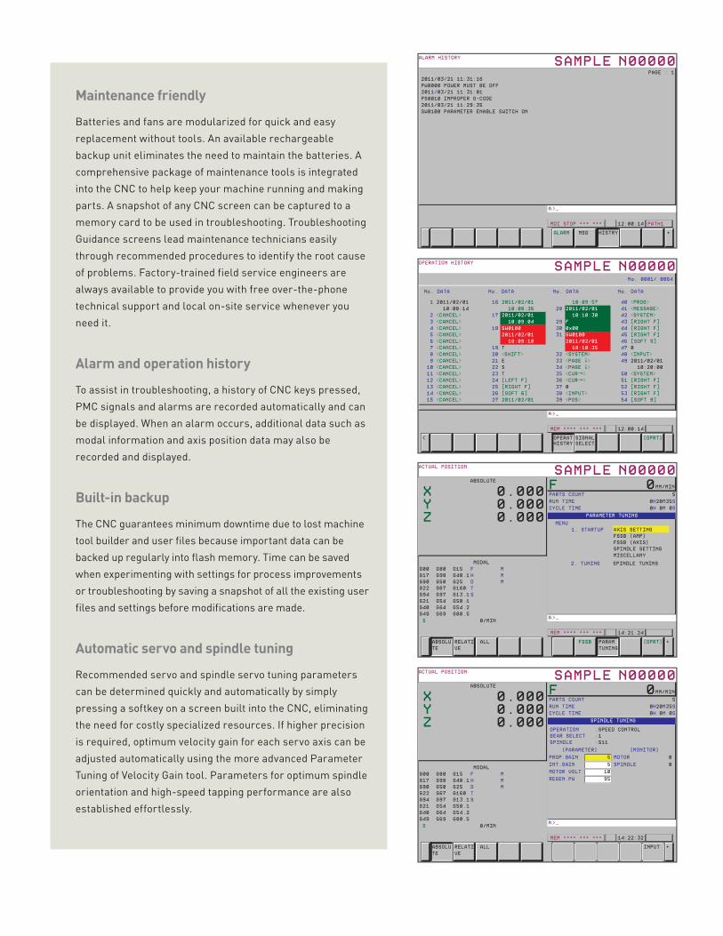
Alarm and operation historyTo assist in troubleshooting, a history of CNC keys pressed,
PMC signals and alarms are recorded automatically and can
be displayed. When an alarm occurs, additional data such as
modal information and axis position data may also be
recorded and displayed.
Built-in backupThe CNC guarantees minimum downtime due to lost machine
tool builder and user files because important data can be
backed up regularly into flash memory. Time can be saved
when experimenting with settings for process improvements
or troubleshooting by saving a snapshot of all the existing user
files and settings before modifications are made.
Automatic servo and spindle tuning Recommended servo and spindle servo tuning parameters
can be determined quickly and automatically by simply
pressing a softkey on a screen built into the CNC, eliminating
the need for costly specialized resources. If higher precision
is required, optimum velocity gain for each servo axis can be
adjusted automatically using the more advanced Parameter
Tuning of Velocity Gain tool. Parameters for optimum spindle
orientation and high-speed tapping performance are also
established effortlessly.
A totally integrated CNC system
Fully digital systemThanks to the limited number of components and their
high-speed inter-connection technologies, the design of the
electrical enclosure is simplified, and allows for a reduction
in wiring. A enhanced fiber optic connection between the
control and the servo and spindle drives provides guaranteed
noise immune data exchange at distances up to 300 feet. A
similar fiber optic connection is utilized between the control
and the display, if they are separated. I/O Link i provides
a fast serial interface between the PMC and I/O devices,
providing up to 4,096 devices. Digital technology throughout
ensures that any data transfer can be performed at high-
speed and error-free.
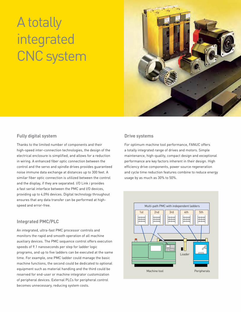
Integrated PMC/PLCAn integrated, ultra-fast PMC processor controls and
monitors the rapid and smooth operation of all machine
auxiliary devices. The PMC sequence control offers execution
speeds of 9.1 nanoseconds per step for ladder logic
programs, and up to five ladders can be executed at the same
time. For example, one PMC ladder could manage the basic
machine functions, the second could be dedicated to optional
equipment such as material handling and the third could be
reserved for end-user or machine integrator customization
of peripheral devices. External PLCs for peripheral control
becomes unnecessary, reducing system costs.
Drive systemsFor optimum machine tool performance, FANUC offers
a totally integrated range of drives and motors. Simple
maintenance, high-quality, compact design and exceptional
performance are key factors inherent in their design. High
efficiency drive components, power source regeneration
and cycle time reduction features combine to reduce energy
usage by as much as 30% to 50%.
Multi-path PMC with independent ladders
Loader
PeripheralsMachine tool
1st 2nd 3rd 4th 5th
FS30i / 31i / 32i
αi Servo motorαi Servo amplifier
αi Separate
detector unit
I/O unit
I/O module
I/O-link
βi amplifier
βis Servo motor
Linear encoders
from another
manufacturer
I/O-link
Control of peripheral devices
Open communication at the machine level As well as FANUC’s own integrated I/O structure, alternative fieldbus systems (Ethernet/IP, DeviceNet,
Profibus-DP, AS-i, I/O Link II, FL-net) may be connected.
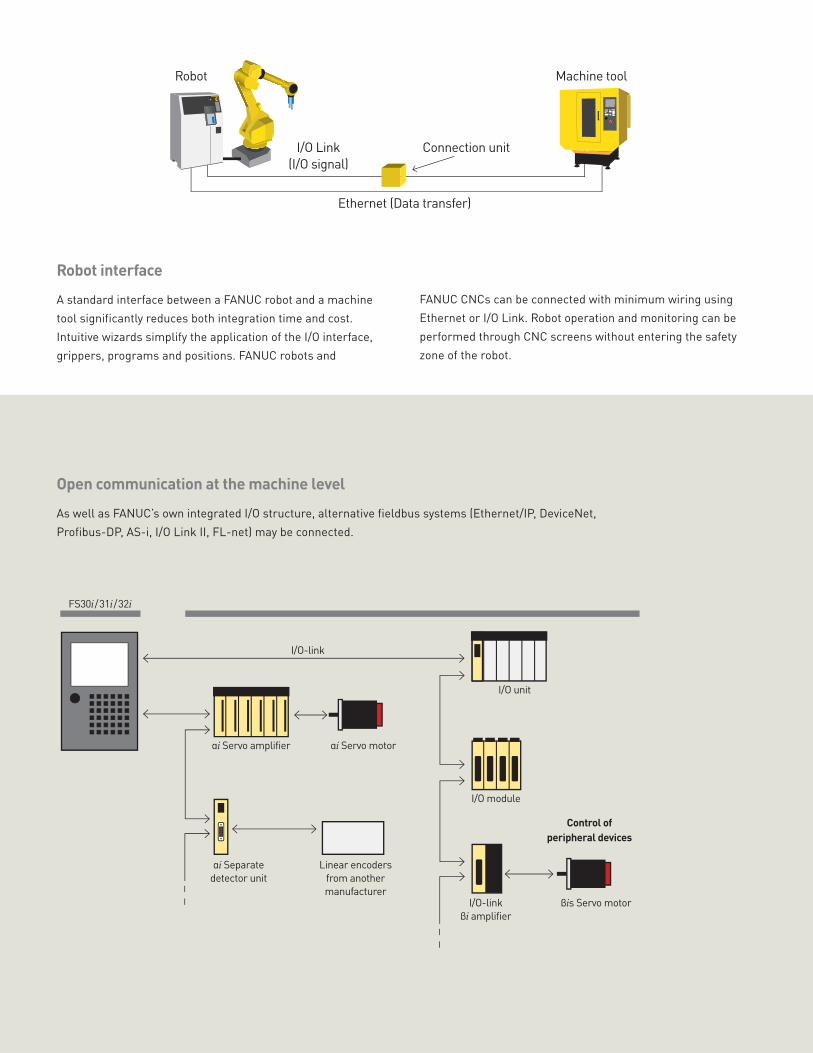
Robot interfaceA standard interface between a FANUC robot and a machine
tool significantly reduces both integration time and cost.
Intuitive wizards simplify the application of the I/O interface,
grippers, programs and positions. FANUC robots and
FANUC CNCs can be connected with minimum wiring using
Ethernet or I/O Link. Robot operation and monitoring can be
performed through CNC screens without entering the safety
zone of the robot.
Machine toolRobot
Ethernet (Data transfer)
Connection unitI/O Link
(I/O signal)
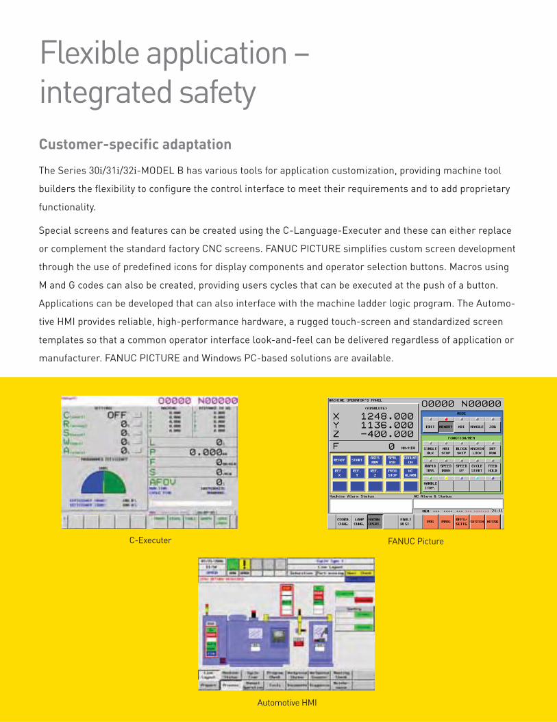
Automotive HMI
C-Executer FANUC Picture
Customer-specific adaptationThe Series 30i/31i/32i-MODEL B has various tools for application customization, providing machine tool
builders the flexibility to configure the control interface to meet their requirements and to add proprietary
functionality.
Special screens and features can be created using the C-Language-Executer and these can either replace
or complement the standard factory CNC screens. FANUC PICTURE simplifies custom screen development
through the use of predefined icons for display components and operator selection buttons. Macros using
M and G codes can also be created, providing users cycles that can be executed at the push of a button.
Applications can be developed that can also interface with the machine ladder logic program. The Automo-
tive HMI provides reliable, high-performance hardware, a rugged touch-screen and standardized screen
templates so that a common operator interface look-and-feel can be delivered regardless of application or
manufacturer. FANUC PICTURE and Windows PC-based solutions are available.
Flexible application – integrated safety
DUALCHECKSAFETY
DUALCHECK
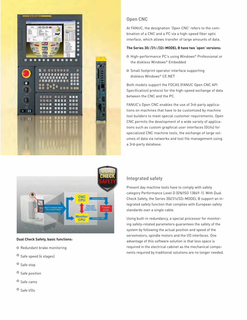
Open CNCAt FANUC, the designation ‘Open CNC’ refers to the com-
bination of a CNC and a PC via a high-speed fiber optic
interface, which allows transfer of large amounts of data.
The Series 30i /31i /32i-MODEL B have two ‘open’ versions:
High-performance PC’s using Windows® Professional or
the diskless Windows® Embedded
Small footprint operator interface supporting
diskless Windows® CE.NET
Both models support the FOCAS (FANUC Open CNC API
Specification) protocol for the high-speed exchange of data
between the CNC and the PC.
FANUC’s Open CNC enables the use of 3rd-party applica-
tions on machines that have to be customized by machine
tool builders to meet special customer requirements. Open
CNC permits the development of a wide variety of applica-
tions such as custom graphical user interfaces (GUIs) for
specialized CNC machine tools, the exchange of large vol-
umes of data via networks and tool file management using
a 3rd-party database.
Dual Check Safety, basic functions:
Redundant brake monitoring
Safe speed (4 stages)
Safe stop
Safe position
Safe cams
Safe I/Os
Integrated safetyPresent day machine tools have to comply with safety
category Performance Level D (EN/ISO 13849-1). With Dual
Check Safety, the Series 30i/31i/32i-MODEL B support an in-
tegrated safety function that complies with European safety
standards over a single cable.
Using built-in redundancy, a special processor for monitor-
ing safety-related parameters guarantees the safety of the
system by following the actual position and speed of the
servomotors, spindle motors and the I/O interfaces. One
advantage of this software solution is that less space is
required in the electrical cabinet as the mechanical compo-
nents required by traditional solutions are no longer needed.
Operational trainingNCGuide is ideal for operational training. All standard CNC
operational screens can be selected and all standard proce-
dures can be practiced. Custom screens provided by the
machine tool builder are supported.
You can create and edit part programs, search for words and
safe start blocks, upload and download part programs, and
test for syntax and tool path geometry errors. Workpiece,
tool geometry and tool wear offsets can all be edited and
their effects visualized to enhance understanding. Users can
expand their knowledge by learning the features available
with newer controls - even before they are installed.
For the most realistic and effective learning environment,
each user can quickly setup configuration to emulate a par-
ticular machine’s CNC.
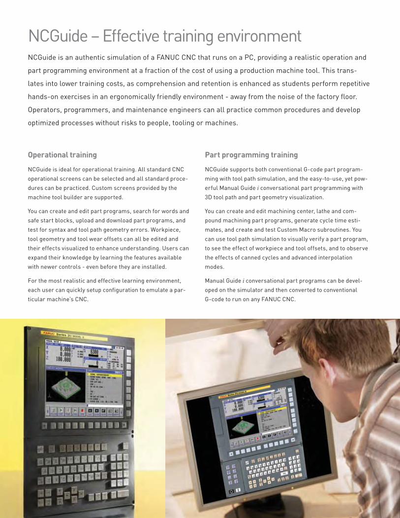
NCGuide – Effective training environmentNCGuide is an authentic simulation of a FANUC CNC that runs on a PC, providing a realistic operation and
part programming environment at a fraction of the cost of using a production machine tool. This trans-
lates into lower training costs, as comprehension and retention is enhanced as students perform repetitive
hands-on exercises in an ergonomically friendly environment - away from the noise of the factory floor.
Operators, programmers, and maintenance engineers can all practice common procedures and develop
optimized processes without risks to people, tooling or machines.
Part programming trainingNCGuide supports both conventional G-code part program-
ming with tool path simulation, and the easy-to-use, yet pow-
erful Manual Guide i conversational part programming with
3D tool path and part geometry visualization.
You can create and edit machining center, lathe and com-
pound machining part programs, generate cycle time esti-
mates, and create and test Custom Macro subroutines. You
can use tool path simulation to visually verify a part program,
to see the effect of workpiece and tool offsets, and to observe
the effects of canned cycles and advanced interpolation
modes.
Manual Guide i conversational part programs can be devel-
oped on the simulator and then converted to conventional
G-code to run on any FANUC CNC.
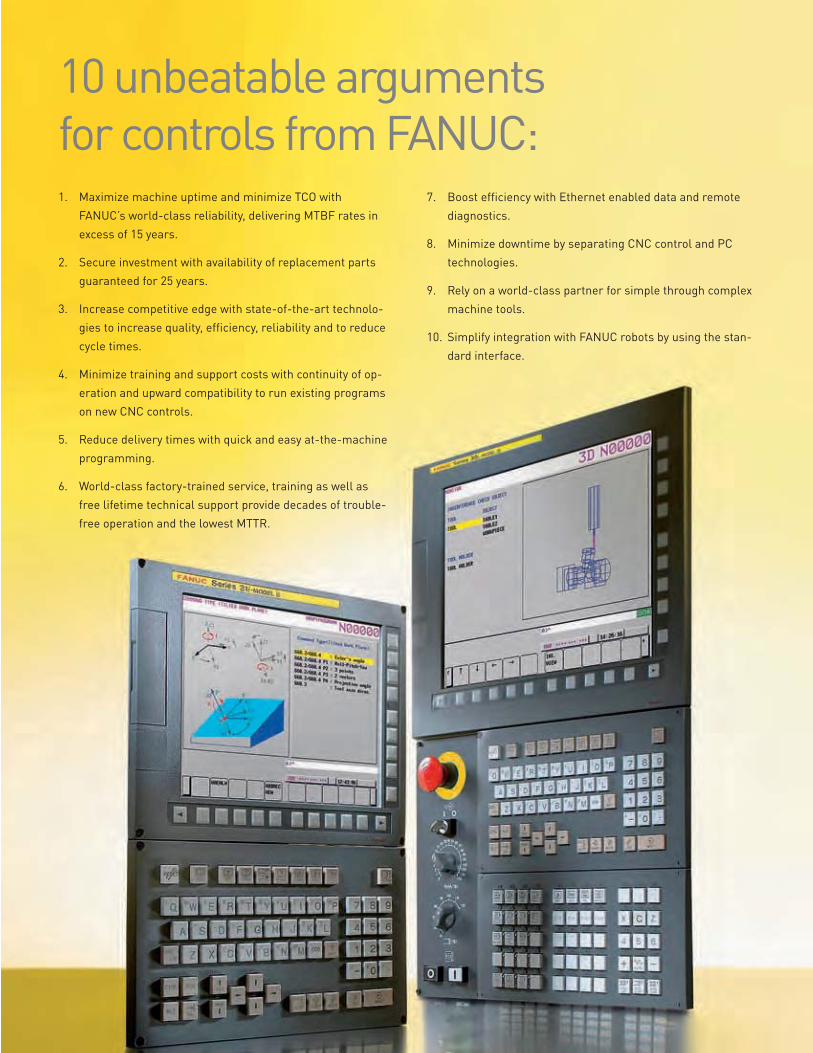
10 unbeatable arguments for controls from FANUC:1. Maximize machine uptime and minimize TCO with
FANUC’s world-class reliability, delivering MTBF rates in
excess of 15 years.
2. Secure investment with availability of replacement parts
guaranteed for 25 years.
3. Increase competitive edge with state-of-the-art technolo-
gies to increase quality, efficiency, reliability and to reduce
cycle times.
4. Minimize training and support costs with continuity of op-
eration and upward compatibility to run existing programs
on new CNC controls.
5. Reduce delivery times with quick and easy at-the-machine
programming.
6. World-class factory-trained service, training as well as
free lifetime technical support provide decades of trouble-
free operation and the lowest MTTR.
7. Boost efficiency with Ethernet enabled data and remote
diagnostics.
8. Minimize downtime by separating CNC control and PC
technologies.
9. Rely on a world-class partner for simple through complex
machine tools.
10. Simplify integration with FANUC robots by using the stan-
dard interface.
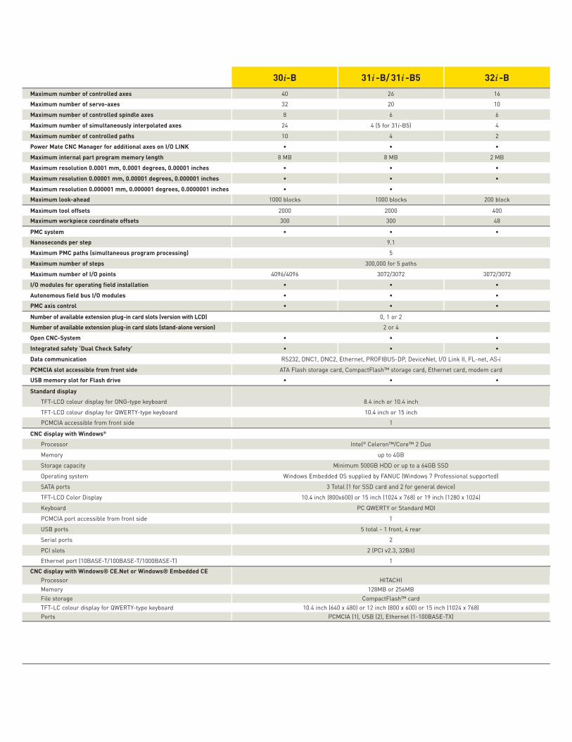
30i-B 31i -B/ 31i -B5 32i -BMaximum number of controlled axes 40 26 16
Maximum number of servo-axes 32 20 10
Maximum number of controlled spindle axes 8 6 6
Maximum number of simultaneously interpolated axes 24 4 (5 for 31i-B5) 4
Maximum number of controlled paths 10 4 2
Power Mate CNC Manager for additional axes on I/O LINKMaximum internal part program memory length 8 MB 8 MB 2 MB
Maximum resolution 0.0001 mm, 0.0001 degrees, 0.00001 inchesMaximum resolution 0.00001 mm, 0.00001 degrees, 0.000001 inchesMaximum resolution 0.000001 mm, 0.000001 degrees, 0.0000001 inchesMaximum look-ahead 1000 blocks 1000 blocks 200 block
Maximum tool offsets 2000 2000 400
Maximum workpiece coordinate offsets 300 300 48
PMC systemNanoseconds per step 9.1
Maximum PMC paths (simultaneous program processing) 5
Maximum number of steps 300,000 for 5 paths
Maximum number of I/O points 4096/4096 3072/3072 3072/3072
I/O modules for operating field installationAutonomous field bus I/O modulesPMC axis control
Number of available extension plug-in card slots (version with LCD) 0, 1 or 2
Number of available extension plug-in card slots (stand-alone version) 2 or 4
Open CNC-SystemIntegrated safety ‘Dual Check Safety’Data communication RS232, DNC1, DNC2, Ethernet, PROFIBUS-DP, DeviceNet, I/O Link II, FL-net, AS-i
PCMCIA slot accessible from front side ATA Flash storage card, CompactFlash™ storage card, Ethernet card, modem card
USB memory slot for Flash drive
Standard displayTFT-LCD colour display for ONG-type keyboard 8.4 inch or 10.4 inch
TFT-LCD colour display for QWERTY-type keyboard 10.4 inch or 15 inch
PCMCIA accessible from front side 1
CNC display with Windows® Processor Intel® Celeron™/Core™ 2 Duo
Memory up to 4GB
Storage capacity Minimum 500GB HDD or up to a 64GB SSD
Operating system Windows Embedded OS supplied by FANUC (Windows 7 Professional supported)
SATA ports 3 Total (1 for SSD card and 2 for general device)
TFT-LCD Color Display 10.4 inch (800x600) or 15 inch (1024 x 768) or 19 inch (1280 x 1024)
Keyboard PC QWERTY or Standard MDI
PCMCIA port accessible from front side 1
USB ports 5 total - 1 front, 4 rear
Serial ports 2
PCI slots 2 (PCI v2.3, 32Bit)
Ethernet port (10BASE-T/100BASE-T/1000BASE-T) 1
CNC display with Windows® CE.Net or Windows® Embedded CEProcessor HITACHI
Memory 128MB or 256MB
File storage CompactFlash™ card
TFT-LC colour display for QWERTY-type keyboard 10.4 inch (640 x 480) or 12 inch (800 x 600) or 15 inch (1024 x 768)
Ports PCMCIA (1), USB (2), Ethernet (1-100BASE-TX)
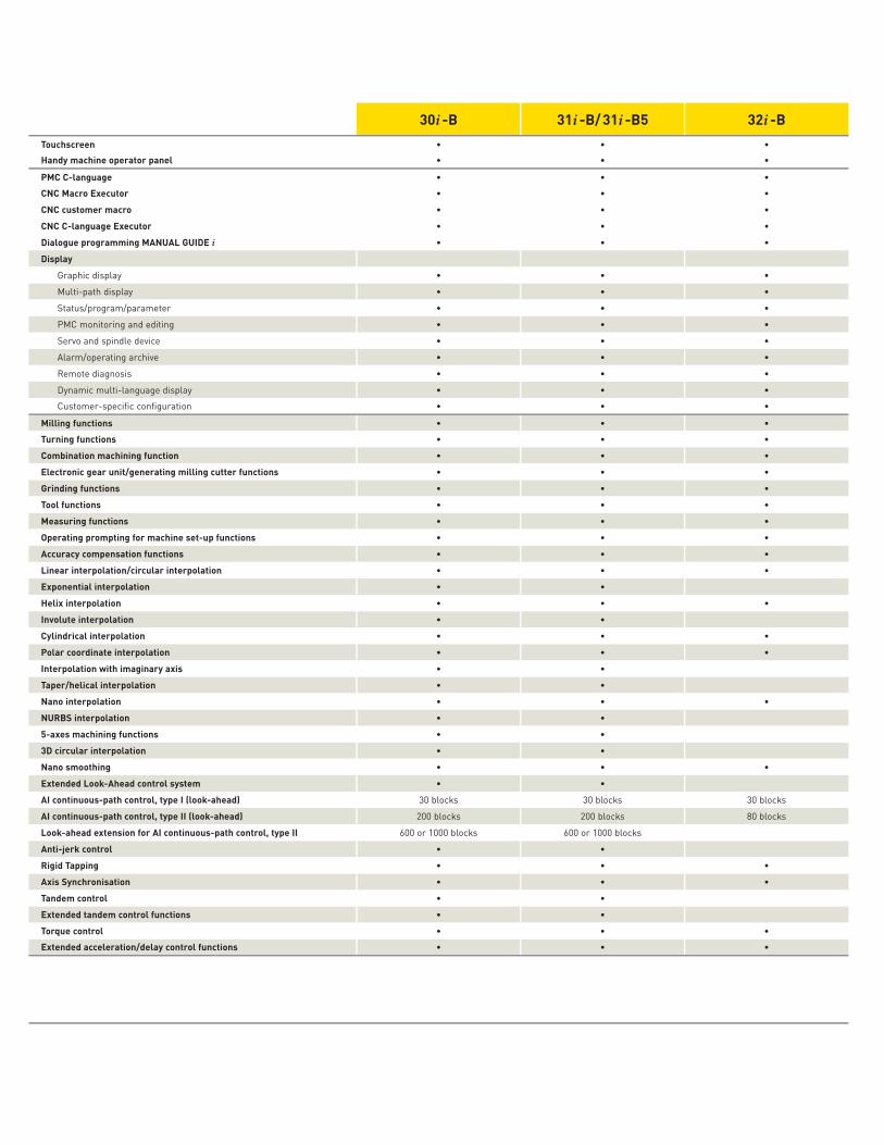
30i -B 31i -B/ 31i -B5 32i -BTouchscreenHandy machine operator panel
PMC C-language CNC Macro Executor CNC customer macro CNC C-language Executor Dialogue programming MANUAL GUIDE iDisplay
Graphic display
Multi-path display
Status/program/parameter
PMC monitoring and editing
Servo and spindle device
Alarm/operating archive
Remote diagnosis
Dynamic multi-language display
Customer-specific configuration
Milling functions Turning functions Combination machining function Electronic gear unit/generating milling cutter functions Grinding functions Tool functions Measuring functions Operating prompting for machine set-up functions Accuracy compensation functions Linear interpolation/circular interpolation Exponential interpolation Helix interpolation Involute interpolation Cylindrical interpolation Polar coordinate interpolation Interpolation with imaginary axis Taper/helical interpolation Nano interpolation NURBS interpolation 5-axes machining functions 3D circular interpolation Nano smoothing Extended Look-Ahead control system AI continuous-path control, type I (look-ahead) 30 blocks 30 blocks 30 blocks
AI continuous-path control, type II (look-ahead) 200 blocks 200 blocks 80 blocks
Look-ahead extension for AI continuous-path control, type II 600 or 1000 blocks 600 or 1000 blocks
Anti-jerk control Rigid Tapping Axis Synchronisation Tandem control Extended tandem control functions Torque control Extended acceleration/delay control functions
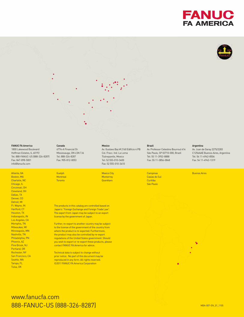
FANUC FA America1800 Lakewood Boulevard
Hoffman Estates, IL 60192
Tel: 888-FANUC-US (888-326-8287)
Fax: 847-898-5001
Canada6774-A Financial Dr.
Mississauga, ON L5N 7J6
Tel: 888-326-8287
Fax: 905-812-0053
MexicoAv. Gustavo Baz # 2160 Edificio 4 PB
Col. Fracc. Ind. La Loma
Tlalnepantle, Mexico
Tel: 52 555-010-3400
Fax: 52 555-010-3410
BrazilAv. Professor Celestino Bourroul 414
São Paulo, SP 02710-000, Brazil
Tel: 55 11-3952-8888
Fax: 55 11-3856-0848
ArgentinaAv. Juan de Garay 2275/2283
C1256AAE Buenos Aires, Argentina
Tel: 54 11-4942-8504
Fax: 54 11-4942-1319
The products in this catalog are controlled based on
Japan’s “Foreign Exchange and Foreign Trade Law”.
The export from Japan may be subject to an export
license by the government of Japan.
Further, re-export to another country may be subject
to the license of the government of the country from
where the product is re-exported. Furthermore,
the product may also be controlled by re-export
regulations of the United States government. Should
you wish to export or re-export these products, please
contact FANUC FA America for advice.
Technical data is subject to change without
prior notice. No part of this document may be
reproduced in any form. All rights reserved.
©2011 FANUC FA America Corporation
MBA-007-EN_01_1105
Atlanta, GA
Boston, MA
Charlotte, NC
Chicago, IL
Cincinnati, OH
Cleveland, OH
Dallas, TX
Denver, CO
Detroit, MI
Ft. Wayne, IN
Hartford, CT
Houston, TX
Indianapolis, IN
Los Angeles, CA
Memphis, TN
Milwaukee, WI
Minneapolis, MN
Nashville, TN
Philadelphia, PN
Phoenix, AZ
Pine Brook, NJ
Portland, OR
Rochester, NY
San Francisco, CA
Seattle, WA
Tampa, FL
Tulsa, OK
Guelph
Montreal
Toronto
Mexico City
Monterrey
Querétaro
Campinas
Caxias do Sul
Curitiba
São Paulo
Buenos Aires
www.fanucfa.com
888-FANUC-US (888-326-8287)


