Page 1
1
Features
Quarter turn (90°) operation
Long life brushless motor
Multi-voltage capable (5610 models only) with auto-voltage
sensing
External LED multi-color diagnostic light
IP67 weatherproof enclosure, UV resistant
ISO5211 multi-flange valve mounting pad
Thermostatically controlled anti-condensation heater
Manual override
Highly visual valve position dome style indicator
Auxiliary limit switches to confirm valve open/closed positions
DPS Digital Positioner option
BSR Battery Backup/Failsafe option
Nominal life >60,000 cycles
Applications
Multi-voltage electric actuators are typically used to automate quarter
turn ball valves, butterfly valves and dampers. The 5610/5615 series
actuators are quick and easy to install with standard ISO5211 multi-
flange mounting and a double square output drive.
Construction
Description
Electric actuator uses power-to-open and power-to-close, stays in the
last known position with power failure. On receipt of a continuous
voltage signal, the motor runs and via a flat gear system rotates the
output drive 90º. The motor is automatically stopped by internal cams
striking limit switches. On receipt of a reversing continuous signal, the
motor turns in the opposite direction reversing the output drive position.
Operation
Optional Functions
BSR: Battery Spring Return - actuator fails to
a safe position with loss of power
DPS: Digital Positioning System - valve
position controlled by either a 4-20mA or
0-10V control signal
Doc: 5610.5615.0419 Cornelius, N.C. • USA www.valworx.com
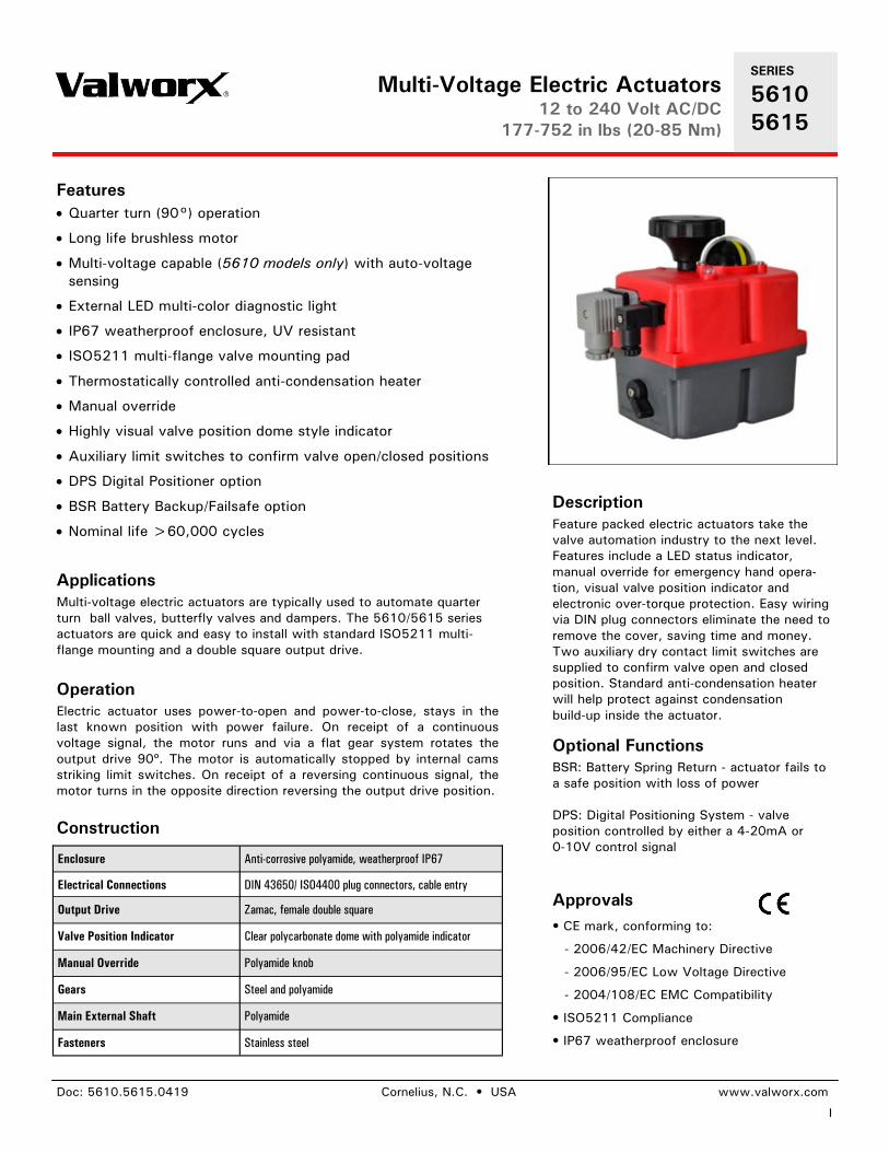
Feature packed electric actuators take the
valve automation industry to the next level.
Features include a LED status indicator,
manual override for emergency hand opera-
tion, visual valve position indicator and
electronic over-torque protection. Easy wiring
via DIN plug connectors eliminate the need to
remove the cover, saving time and money.
Two auxiliary dry contact limit switches are
supplied to confirm valve open and closed
position. Standard anti-condensation heater
will help protect against condensation
build-up inside the actuator.
Enclosure Anti-corrosive polyamide, weatherproof IP67
Electrical Connections DIN 43650/ ISO4400 plug connectors, cable entry
Output Drive Zamac, female double square
Valve Position Indicator Clear polycarbonate dome with polyamide indicator
Manual Override Polyamide knob
Gears Steel and polyamide
Main External Shaft Polyamide
Fasteners Stainless steel
Approvals
• CE mark, conforming to:
- 2006/42/EC Machinery Directive
- 2006/95/EC Low Voltage Directive
- 2004/108/EC EMC Compatibility
• ISO5211 Compliance
• IP67 weatherproof enclosure
SERIES
5610
5615
Multi-Voltage Electric Actuators 12 to 240 Volt AC/DC
177-752 in lbs (20-85 Nm)
Page 2
2
SERIES
5610
5615
Doc: 5610.5615.0419 Cornelius, N.C. • USA www.valworx.com
Manual override
Weatherproof enclosure
rated IP67
Electrical connections via
standard DIN style plug
connectors
Corrosion resistant polyamide
enclosure with UV protection
Auto-Manual selector lever
Highly visual dome position
indicator
Auxiliary limit switches to
confirm open and closed
position
External LED diagnostic light
Thermostatically controlled
anti-condensation heater
Heavy Duty brushless motor
ISO5211 International
standard multi-flange valve
mounting pad
Construction Features
Typical Applications
Multi-Voltage Electric Actuators 12 to 240 Volt AC/DC
177-752 in lbs (20-85 Nm)
Page 3
3
Doc: 5610.5615.0419 Cornelius, N.C. • USA www.valworx.com
Stock Number 561020E 561055E 561085E
Voltage Range AC or DC Auto-Voltage Sensing
(1ph,50/60Hz), - 0/+5%
24~240v AC or DC 24~240v AC or DC 24~240v AC or DC
Cycle Time - Seconds/0-90° (no load) 9 sec 13 sec 29 sec
Maximum Run Torque
177 in lbs
20 Nm
486 in lbs
55 Nm
752 in lbs
85 Nm
Maximum Break Torque 221 in lbs
25 Nm
530 in lbs
60 Nm
796 in lbs
90 Nm
Duty Cycle 75%
Over-load Protection Electronic over-torque with LED status light
Enclosure Anti-corrosive polyamide with UV protection
Enclosure Rating IP67 weatherproof
Working Angle (rotation) 90 degrees
Temperature Range -4~+158° F (-20~+70° C)
Motor Switches 2 x SPST limit switches
Position Confirmation Switches 2 x SPST limit switches, 3A @125/250VAC, 30VDC resistive load
Anti-condensation Heater 4 watts
Electrical Connections Plug connectors per DIN EN175301-803, cable entry, screw terminals
Current (Full Load Amps) 24VDC
24VAC
110VAC
240VAC
0.97A
1.28A
0.30A
0.16A
1.63A
1.98A
0.43A
0.21A
1.22A
1.50A
0.33A
0.18A
Valve Mounting Interface per ISO5211 F03, F04,
F05
F05, F07 F05, F07
Output Drive - Female Double Square 11mm 14mm 17mm
Weight 4.0 lbs (1.8 kg) 5.3 lbs (2.4 kg) 6.2 lbs (2.8 kg)
Specifications
SERIES
5610
5615
Multi-Voltage Electric Actuator Models 24 to 240 Volt AC/DC
177-752 in lbs (20-85 Nm)
Page 4
4
Doc: 5610.5615.0419 Cornelius, N.C. • USA www.valworx.com
SERIES
5610
5615
Specifications
Single Voltage Electric Actuator Models 12 Volt AC/DC
177-752 in lbs (20-85 Nm)
Stock Number 561520 561555 561585
Voltage Range AC or DC Auto-Voltage Sensing
(1ph,50/60Hz), - 0/+5%
12v AC or DC 12v AC or DC 12v AC or DC
Cycle Time - Seconds/0-90° (no load) 9 sec 13 sec 29 sec
Maximum Run Torque
177 in lbs
20 Nm
486 in lbs
55 Nm
752 in lbs
85 Nm
Maximum Break Torque 221 in lbs
25 Nm
530 in lbs
60 Nm
796 in lbs
90 Nm
Duty Cycle 75%
Over-load Protection Electronic over-torque with LED status light
Enclosure Anti-corrosive polyamide with UV protection
Enclosure Rating IP67 weatherproof
Working Angle (rotation) 90 degrees
Temperature Range -4~+158° F (-20~+70° C)
Motor Switches 2 x SPST limit switches
Position Confirmation Switches 2 x SPST limit switches, 3A @125/250VAC, 30VDC resistive load
Anti-condensation Heater 4 watts
Electrical Connections Plug connectors per DIN EN175301-803, cable entry, screw terminals
Current (Full Load Amps) 12VDC
12VAC
1.95A
2.28A
3.42A
3.78A
2.28A
2.65A
Valve Mounting Interface per ISO5211 F03, F04,
F05
F05, F07 F05, F07
Output Drive - Female Double Square 11mm 14mm 17mm
Weight 4.0 lbs (1.8 kg) 5.3 lbs (2.4 kg) 6.2 lbs (2.8 kg)
Page 5
5
Doc: 5610.5615.0419 Cornelius, N.C. • USA www.valworx.com
Optional DPS - Digital Positioner System
Kit Stock No. Input Signal For Actuators
561101E 4-20mA 5610 (design series E),
5615
561102E 0-10VDC 5610 (design series E),
5615
• DPS kits are a factory installed option
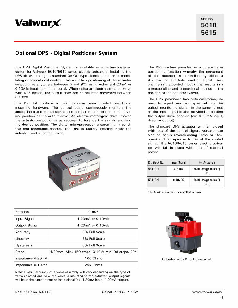
The DPS Digital Positioner System is available as a factory installed
option for Valworx 5610/5615 series electric actuators. Installing the
DPS kit will change a standard On-Off type electric actuator to modu-
lating or proportional control. This will allow positioning of the actuator
output drive anywhere between 0 and 90° using either a 4-20mA or
0-10vdc input command signal. When using an electric actuated valve
with DPS option, the output flow can be adjusted anywhere between
0-100%.
The DPS kit contains a microprocessor based control board and
mounting hardware. The control board continuously monitors the
analog input and output signals and compares them to the actual phys-
ical position of the output drive. An electric motor/gear drive moves
the actuator output drive as required to balance the signals and find
the desired position. The digital microprocessor ensures highly sensi-
tive and repeatable control. The DPS is factory installed inside the
actuator, under the red cover.
Rotation 0-90°
Input Signal 4-20mA or 0-10vdc
Output Signal 4-20mA or 0-10vdc
Accuracy 3% Full Scale
Linearity 2% Full Scale
Hysteresis 3% Full Scale
Steps 4/20mA: Min. 150 steps, 0-10V: Min. 98 steps/ 90°
Impedance 4-20mA 100 Ohms
Impedance 0-10vdc 25K Ohms
The DPS system provides an accurate valve
positioning function whereby the movement
of the actuator is controlled by either a
4-20mA or 0-10vdc control signal. Any
change in the control input signal results in a
corresponding and proportional change in the
position of the actuator (valve).
The DPS positioner has auto-calibration, no
need to adjust zero and span settings. An
output monitoring signal, in the same format
as the input signal is also provided to confirm
the output drive position (ex: 4-20mA input,
4-20mA output).
The standard DPS actuator will fail closed
with loss of the control signal. Actuator can
also be setup reverse-acting (4ma or 0v=
open) and fail open with loss of the control
signal. The 5610/5615 series electric actua-
tor will fail in place with loss of external
power.
Note: Overall accuracy of a valve assembly will vary depending on the type of
valve selected and how the valve is mounted to the actuator. Output signals
will be in the same format as input signal (ex: 4-20mA input, 4-20mA output).
Actuator with DPS kit installed
SERIES
5610
5615
Page 6
6
Doc: 5610.5615.0419 Cornelius, N.C. • USA www.valworx.com
Optional BSR - Battery Spring Return
• BSR kits are a factory installed option
The installed BSR kit will provide enough
power to move the actuator/valve to a
failsafe position with loss of external power.
The kit can be ordered as fail closed or fail
open as required.
The actuator operates in the normal power
open and power close mode while external
power is available. Internal circuitry monitors
the incoming main power and automatically
switches within a few seconds to the battery
backup with loss of external power. The
battery will then provide enough power to
move the actuator to a failsafe position.
Under normal operation the external control
power will trickle charge the battery and
maintain a full charge.
In the normal mode of operation, an LED
status light located on top of the actuator
cover will be continuously lit. With a loss of
power, the LED status light will blink slowly.
On resumption of external power, conditional
that the actuator control signal remained
unchanged, the actuator will reset to the
position it saw at the time of the main power
failure.
The BSR–Battery Spring Return kit is available as a factory installed
option for Valworx 5610/5615 series electric actuators. The BSR kit
will work with both on-off models and actuators with DPS positioners.
The battery failsafe system provides an alternative source of power to
drive the actuator to a preset failsafe position in the event of an
external power failure. The industrial quality battery is constantly trick-
le charged during normal operation to assure maximum charge when
required. The battery kit is installed under the actuator cover. No
separate modules or boxes are required.
In many applications, the BSR battery spring return function tends to
be a very economical option when compared to the alternate true
mechanical spring return actuator. Valworx actuators with the BSR
option are much smaller, lighter and less expensive.
Valworx Actuator with
BSR Option
561020E
561520
561055E
561555
561085E
561585
Working operations without
recharge, with 100% initial
battery charge
10 10 10
Recharge time per working
operation
15 min 48 min 58 min
Full Charge Time 100% 28 h 28 h 28 h
Battery capacity +/-5% 2200 mA 2200 mA 2200 mA
Kit Stock Description For Actuators
561104E 5610 BSR Battery Spring
Return Kit, Fail Closed
5610 (design
series E), 5615
561105E 5610 BSR Battery Spring
Return Kit, Fail Open
5610 (design
series E), 5615
BSR kit installed under red cover
SERIES
5610
5615
Page 7
7
Doc: 5610.5615.0419 Cornelius, N.C. • USA www.valworx.com
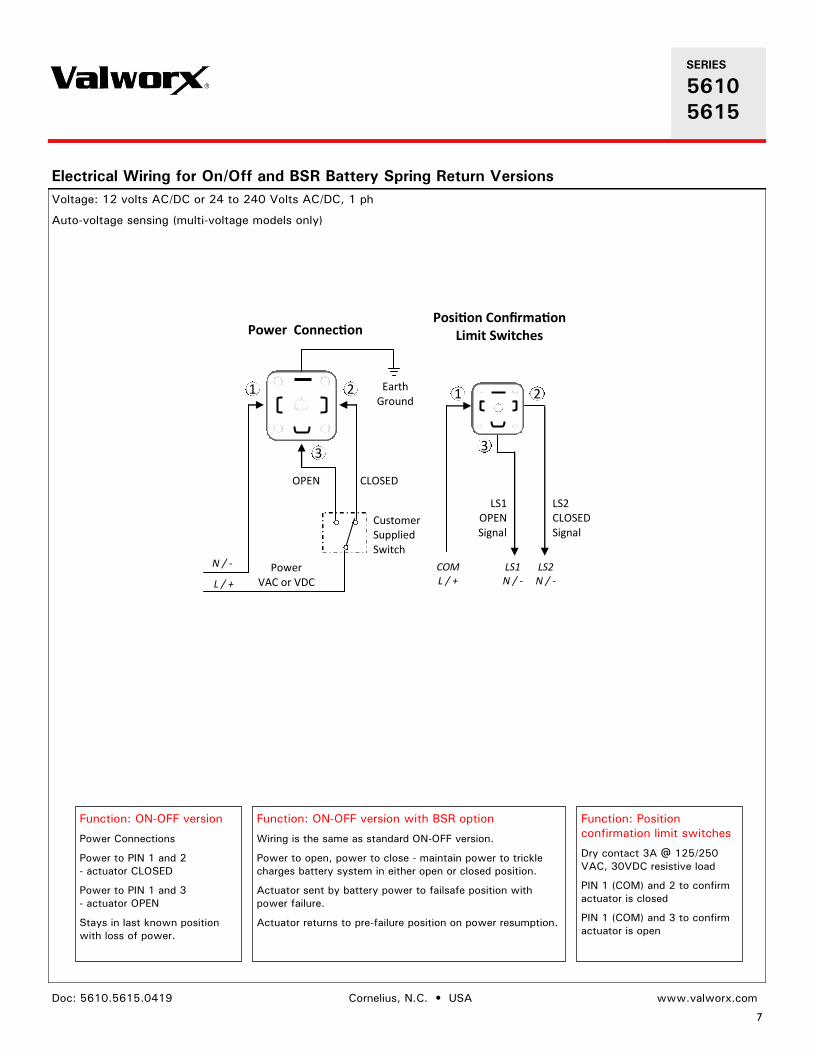
Function: ON-OFF version
Power Connections
Power to PIN 1 and 2
- actuator CLOSED
Power to PIN 1 and 3
- actuator OPEN
Stays in last known position
with loss of power.
Function: ON-OFF version with BSR option
Wiring is the same as standard ON-OFF version.
Power to open, power to close - maintain power to trickle
charges battery system in either open or closed position.
Actuator sent by battery power to failsafe position with
power failure.
Actuator returns to pre-failure position on power resumption.
Electrical Wiring for On/Off and BSR Battery Spring Return Versions
Voltage: 12 volts AC/DC or 24 to 240 Volts AC/DC, 1 ph
Auto-voltage sensing (multi-voltage models only)
1 2
3
CLOSED OPEN
Customer Supplied Switch
Power Connection
LS1 OPEN Signal
LS2 CLOSED Signal
Position Confirmation Limit Switches
1 2
3
N / -
L / +
LS1 N / -
LS2 N / -
COM L / +
Earth Ground
Power VAC or VDC
Function: Position
confirmation limit switches
Dry contact 3A @ 125/250
VAC, 30VDC resistive load
PIN 1 (COM) and 2 to confirm
actuator is closed
PIN 1 (COM) and 3 to confirm
actuator is open
SERIES
5610
5615
Page 8
8
Doc: 5610.5615.0419 Cornelius, N.C. • USA www.valworx.com
Function: Actuators with DPS—Digital Positioner Option
Power open, power close - actuator movement controlled by 4-20mA or 0-10VDC input signal.
Standard operation: 4mA or 0V = actuator closed, 20mA or 10V = actuator open (can be
setup reverse acting).
Actuator closes with loss of control signal, stays in last known position with loss of main
power.
Output monitoring signal (in same format as supply signal) provided as standard.
Electrical Wiring for Actuators with DPS Digital Positioner Option
Voltage: 12 Volts AC/DC or 24 to 240 Volts AC/DC (auto-voltage sensing on multi-voltage models only), 1 ph
Control Signal: 4-20mA or 0-10 VDC
1 2
Power Connection
LS1 OPEN Signal
LS2 CLOSED Signal
Position Confirmation Limit Switches
1 2
3
N / -
L / +
LS1 N / -
LS2 N / -
COM L / +
Earth Ground
DPS Positioner Control Signals 4-20mA/0-10v
2 1
3
+ -Input
+ Output
Power VAC or VDC
Function: Position
confirmation limit switches
Dry contact 3A @ 125/250
VAC, 30VDC resistive load
PIN 1 (COM) and 2 to confirm
actuator is closed
PIN 1 (COM) and 3 to confirm
actuator is open
SERIES
5610
5615
Page 9
9
Doc: 5610.5615.0419 Cornelius, N.C. • USA www.valworx.com
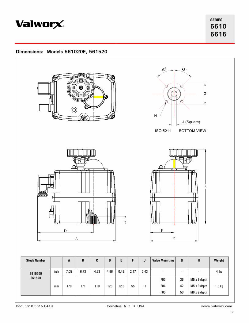
Dimensions: Models 561020E, 561520
Stock Number A B C D E F J Valve Mounting G H Weight
561020E
561520
inch 7.05 6.73 4.33 4.96 0.49 2.17 0.43 - - - 4 lbs
mm 179 171 110 126 12.5 55 11
F03
F04
F05
36
42
50
M5 x 9 depth
M5 x 9 depth
M6 x 9 depth
1.8 kg
SERIES
5610
5615
Page 10
10
Doc: 5610.5615.0419 Cornelius, N.C. • USA www.valworx.com
Dimensions: Models 561055E, 561555
Stock Number A B C D E F J Valve Mounting G H Weight
561055E
561555
inch 6.97 7.72 4.33 4.96 0.75 2.17 0.55 - - - 5.3 lbs
mm 177 196 110 126 19 55 14
F05
F07
50
70
M6 x 25 depth
M8 x 25 depth 2.4 kg
A
DE
C
F
B
45° 45°
G
J (Square)
H
F ISO 5211 BOTTOM VIEW
SERIES
5610
5615
Page 11
11
Doc: 5610.5615.0419 Cornelius, N.C. • USA www.valworx.com
Dimensions: Models 561085E, 561585
Stock Number A B C D E F S Valve Mounting G H Weight J
561085C
561585
inch 6.97 7.72 4.33 4.96 0.75 2.17 0.69 - - - 6.2 lbs 0.67
mm 177 196 110 126 19 55 17.6
F05
F07
50
70
M6 x 25 depth
M8 x 25 depth 2.8 kg 17
A
DE
C
F
BS
F ISO 5211 BOTTOM VIEW
45° 45°
G
J (Square)
H
SERIES
5610
5615