GENERAL SPECIFICATIONS 7DN25 (1") & DN50 (2") - Screwed
GENERAL SPECIFICATIONS 8DN80 (3") & DN200 (8") - Flanged
GENERAL SPECIFICATIONS 9DN250 (10") & DN300 (12") - Flanged
SELECTION & POSITIONING - SERIES RBXc 10-12
SURGE & WATERHAMMER PROTECTION 13-14
SMALL ORIFICE DISCHARGE PERFORMANCE 15
WHY VENT-O-MAT SERIES RBXc 16
PURCHASE SPECIFICATIONS 17
ORDERING GUIDE & TEST SPECIFICATION 18
CONTENT PAGE
CATALOGUE INDEX
R
Series RBXc
OPERATIONPRE NOTES:
VENTING OF A FILLING PIPELINE (SUB CRITICAL WATER APPROACH VELOCITY)
Air enters Orifice (3), travels through the annular space between the cylindrical floats (4), (5), and (6) and the valveChamber Barrel (2) and discharges from the Large Orifice (1) into atmosphere.
information subject to change without prior noticepage: 1
revision date: Feb 2008
1
6
45
2
3
1. VENTING OFAFILLING PIPELINE:
2. SURGEALLEVIATION - PIPELINE PRESSURIZED:
3. PRESSURIZEDAIR RELEASE FROMAFULL PIPELINE:
4. OPERATION OF DN250, DN300 & DN400 MAY DIFFER FROM BELOW.
The operation of a kinetic air release valve is such that fast approaching water is almost instantaneously halted bythe valve's closure without the shock cushioning benefit of any retained air in the pipeline. Consequently a transientpressure rise or shock of potentially damaging proportions can be generated in a pipeline system, even at normalfilling rates.
In addition to venting through the Large Orifice (1) when water approach velocities are sub critical, the Vent-O-Matseries RBXc air release valves feature an automatic 'Anti-Shock' Orifice (8) device that serves to decelerate waterapproaching at excessive speed, thereby limiting pressure rise to a maximum of 1.5 x rated working pressure of thevalve.
In instances where a pipeline experiences water column separation due to pump stoppage, high shock pressurescan be generated when the separated water column rejoins.
The Vent-O-Mat series RBXc takes in air through the unobstructed large orifice when water column separationoccurs, but controls the discharge of air through the 'Anti-Shock' Orifice as the separated column commences torejoin. The rejoining impact velocity is thereby sufficiently reduced to prevent an unacceptably high surge pressurein the system. In the same way the series RBXc valve prevents high surge pressures resulting from liquidoscillation in a pipeline.
Effective discharge by the valve of pressurized air depends on the existence of a 'CRITICAL RELATIONSHIP'between the area of the Small Orifice (7) and the mass of Control Float (4), i.e. the mass of the float must be greaterthan the force created by the working pressure acting on the orifice area. If the float is relatively too light or the orificearea relatively too great, the float will be held against the orifice, even when not buoyed, and air discharge will notbe effected.
To ensure that the correct 'CRITICAL RELATIONSHIP' exists the requisite 'DROP TEST' described under TESTSPECIFICATION on page 18 must be applied to any air release valve which is intended for discharge ofpressurized air.
R
Series RBXc
OPERATION
1
86
4
5
6
1
7
2
3
5
2
3
1
6
4
9
VENTING OF A FILLING PIPELINE (EXCESSIVE WATER APPROACH VELOCITY)
In reaction to increased air flow, Float (6) closes Large Oriface (1) and air is forced through the Anti Shock Oriface(8) resulting in deceleration of the approaching water due to the resistance of rising air pressure in the valve.
Attention is drawn to Pre Note 1 and 2 on page 1.
PRESSURISED AIR RELEASE FROM A FULL PIPELINE
Subsequent to the filling of a pipeline, liquid enters the valve Barrel Chamber (2) and the Floats (4), (5) and (6) arebuoyed so that the Large Orifice (1) is closed by Float (6). The valve will then become internally pressurised. Aminimal working pressure of < 0.5 bar (7.3 psi) acting on the relatively large area of the Orifice (1) will lock Float(6) into the closed position across the Large Orifice (1).
Disentrained airrises through the liquid and accumulates in the valve chamber. When the volume of air is sufficientto displace the liquid, Float (4) will no longer be buoyant and will gravitate downwards thereby opening the SmallOrifice (7) and allowing accumulated air to be discharged into atmosphere. As air is discharged the liquid raisesthe Float (4) and re-seals the Small Orifice (7) and prevents the escape of liquid.
Specific attention is drawn to pre note 3 on page 1.
VACUUM RELIEF (AIR INTAKE) OF A DRAINING PIPELINE
Simultaneous drainage of liquid from Valve Chamber (2) causes Floats (4), (5) and (6) to gravitate downwards intothe Baffle Plate (9), thereby allowing atmospheric air through the valve to rapidly displace draining liquid in thepipeline and prevent potentially damaging internal negative pressure..
information subject to change without prior noticepage: 2
revision date: Feb 2008
R
RECOMMENDED INSTALLATION ARRANGEMENTS
Series RBXc
information subject to change without prior notice
AIR VENT (AIR IN)DIAMETER EQUAL
OR GREATER THANNB OF AIR VALVE
AIR VENT (AIR OUT)DIAMETER EQUAL
OR GREATER THANNB OF AIR VALVE
MANHOLE
STONE
AIR
WATER
LOWER SUMP TO ALLOW DRAINAGE BY SUMP PUMP
VALVE CHAMBER
AIR ACCUMULATOR
d = 0.5 DMIN.h = D MIN.
D
TYPE 1 TYPE 2
TYPE 3(Screwed)
page: 3revision date: Feb 2008
R
Series RBXc
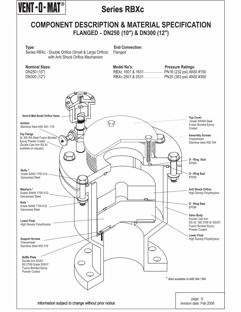
Top FlangeGr 300 WA Steel Fusion Bonded Epoxy Powder Coated(Ductile Cast Iron SG 42 available on request)
Top FloatHigh Density Polyethylene
NozzleStainless Steel AISI 316
Nozzle SeatNatural Rubber
Support ScrewsCheeseheadStainless Steel 316
Baffle PlateStainless Steel AISI 316
COMPONENT DESCRIPTION & MATERIAL SPECIFICATIONSCREWED - DN50 (2")
Top FlangeGr 300 WA Steel Fusion BondedEpoxy Powder Coated(Ductile Cast Iron SG 42available on request)
Series RBXc
information subject to change without prior notice
RR
Series RBXc
COMPONENT DESCRIPTION & MATERIAL SPECIFICATIONFLANGED - DN250 & DN300(10") (12")
information subject to change without prior noticepage: 6
revision date: Feb 2008
* Also available in AISI 304 / 304
R
Series RBXc
GENERAL SPECIFICATIONSSCREWED - DN50 (2")SCREWED
Type:
End Connection:
Nominal Sizes:
Model No's: Pressure Ratings bar (psi):
Operating Pressure Range - bar (psi):
Operating Temperature Range:
Acceptable Media:
Function:
Materials of Construction:Installation:
Standard Factory Tests:
Double Orifice (Small & Large Orifice) with Anti Shock Orificemechanism.
Screwed BSP/ NPT female
DN50 (2")
RBXc 2511 & 2521 25 bar (363 psi)
Min Max.25 bar (363 psi) 0.5 (7.2) 25 (363)
0 C (35 F) to 85 C (185 F)
Potable or strained raw water.
i) High volume air discharge - pipeline filling.ii) High volume air intake - pipeline drainingiii) Pressurized air discharge - pipeline filled.iv) Surge dampening - high velocity air discharge, water
column separation & liquid oscillation.
- see page 4- see page 3
i) Hydrostatic - 1.5 x max. rated working pressureii) Low head leak - 0.5 bar (7.2 psi)iii) Small orifice function at max. rated working pressure
(minimum 1 valve in 10).
0 0 0 0
OVERALL DIMENSIONS & WEIGHTS
information subject to change without prior notice
A
B
D
C
A
DN MODELNo. PRESSURE RATING A B C D WEIGHTmm in. mm in. mm in. kg. lbs
GENERAL SPECIFICATIONSFLANGED - DN50 (2”) TO DN200 (8")
Type:
End Connection:
Nominal Sizes:
Model No's: Pressure Ratings bar (psi):
Operating Pressure Range - bar (psi):
Operating Temperature Range:
Acceptable Media:
Function:
Materials of Construction:Installation:
Standard Factory Tests:
Double Orifice (Small & Large Orifice) with Anti Shock Orificemechanism.
Flange for Alignment to;BS EN1515 PN 16 & PN 25SABS 1123 - Tables 1600/3 & 2500/3ANSI B16.5 Class 150 & Class 300
DN50 (3") & DN200 (8")
RBXc 1601 16 bar (232 psi)RBXc 2501 25 bar (363 psi)
Min Max.16 bar (232 psi) 0.5 (7.2) 16 (232)25 bar (363 psi) 0.5 (7.2) 25 (363)
0 C (35 F) to 85 C (185 F)
Potable or strained raw water.
i) High volume air discharge - pipeline filling.ii) High volume air intake - pipeline drainingiii) Pressurized air discharge - pipeline filled.iv) Surge dampening - high velocity air discharge, water
column separation & liquid oscillation.
- see page 5- see page 3
i) Hydrostatic - 1.5 x max. rated working pressureii) Low head leak - 0.5 bar (7.2 psi)iii) Small orifice function at max. rated working pressure
(minimum 1 valve in 10).
0 0 0 0
OVERALL DIMENSIONS & WEIGHTS
page: 8revision date: Feb 2008
A
B
AVE
N
T-O-MA
T
RBX
information subject to change without prior notice
GENERAL SPECIFICATIONSFLANGED - DN250 (10") & DN300 (12")
Type:
End Connection:
Nominal Sizes:
Model No's: Pressure Ratings bar (psi):
Operating Pressure Range - bar (psi):
Operating Temperature Range:
Acceptable Media:
Function:
Materials of Construction:Installation:
Standard Factory Tests:
Double Orifice (Small & Large Orifice) with Anti Shock Orificemechanism.
Flange for Alignment to;BS EN1515 PN 16 & PN 25SABS 1123 - Tables 1600/3 & 2500/3ANSI B16.5 Class 150 & Class 300
DN250 (10") & DN300 (12")
RBXc 1601 & 1631 16 bar (232 psi)RBXc 2501 & 2531 25 bar (363 psi)
Min Max.16 bar (232 psi) 0.5 (7.2) 16 (232)25 bar (363 psi) 0.5 (7.2) 25 (363)
0 C (35 F) to 85 C (185 F)
Potable or strained raw water.
i) High volume air discharge - pipeline filling.ii) High volume air intake - pipeline drainingiii) Pressurized air discharge - pipeline filled.iv) Surge dampening - high velocity air discharge, water
column separation & liquid oscillation.
- see page 6- see page 3
i) Hydrostatic - 1.5 x max. rated working pressureii) Low head leak - 0.5 bar (7.2 psi)iii) Small orifice function at max. rated working pressure
(minimum 1 valve in 10).
0 0 0 0
OVERALL DIMENSIONS & WEIGHTS
information subject to change without prior noticepage: 9
information subject to change without prior noticepage: 10
revision date: Feb 2008
PRE-NOTES
Sizing for Vacuum
Sizing for Discharge
Pressurized Air Discharge
Surge Alleviation
The functional limits of an air valve are governed by three physical laws namely: Joukowski's Equation Boyle's Law andPascal's Law. Air valve operation however is also dependent on design and internal configuration, and can varydramatically from manufacturer's product to manufacturer's product, within the parameters of what is physically possible.The basis of the Vent -O- Mat design is in the understanding of these laws, which have been used to design an air releaseand vacuum break valve that provides the optimum usable safe performance relative to all functions. The followingsummary is a general guideline of factors to consider when sizing air valves.
Calculate necessary valve orifice sizes independently for each apex point.
Determine the smallest air release and vacuum break valve capable of admitting air into the pipeline equal to the potentialwater flow out of the pipeline whilst not exceeding a differential pressure that would put the pipeline and gasket joints atrisk. We recommend 0.35 bar (5psi) Dp for steel pipe or lower if GRP, uPVC or HDPE pipe is being utilised. This exercise issimplified on pages 11 and 12 of this catalogue. Be cautious of air valve designs with spherical floats as a low pressurezone is created above the float which causes it to partially close off the large orifice during air intake.
Note that vacuum protection is dependent on valve size selection and orifice size relative to the nominal size of the valve.In sizing air valves be cautious of designs with restricted orifice diameters, i.e., orifice diameters that are smaller than thenominal size of the valve, as this could lead to insufficient vacuum protection and pipe collapse if not accommodated for.Vent -O- Mat large orifice diameters and flow path through the ale is equal to the nominal size of the valve e.g. a DN100(4") ale has a 100mm (4") orifice. This ensures the least possible resistance to the intake of air and consequently the leastpossible negative pressure within a draining pipeline.
If a Vent -O- Mat air valve is sized correctly for air intake, discharge should not be a factor in sizing as all air will bedischarged through the large orifice or "Anti-Shock" orifice (refer to RBXc operation on pages 1 and 2 of this catalogue). Ifthis information is used for the sizing of air valves other than Vent-O-Mat recommend that ale be selected that is capable ofdischarging air equal to the filling rate, whilst not exceeding a differential of 0.05 bar (0.7) psi across the large orifice inorder to prevent pressure surge and water hammer.
Effective discharge by an air release and vacuum break vale of pressurized air depends on the existence of a "CriticalRelationship" between the area of the small orifice and the mass of the control float, i.e., the mass of the float must begreater than the force created by the working pressure acting on the orifice area. If the float is relatively too light or theorifice area relatively too great, the float will be held against the orifice even when not buoyed, and air discharge will nottake place.
It is imperative, due to the unpredictable nature of pipeline operation, that every air release and vacuum break valveshould as standard, incorporate a surge and water hammer alleviation mechanism. This mechanism should only beactivated in the instance of high velocity air discharge or pump trip (where the separated liquid columns rejoin at excessivevelocities). The alleviation of surge and/or water hammer must be achieved by deceleration of the approaching liquid priorto valve closure (see operation of RBXc on pages 1 and 2 of this catalogue). Relief mechanisms that act subsequent tovalve closure cannot react in the low millisecond time span required and are therefore unacceptable (refer to pages 13and 14 of this catalogue).
Kindly contact the manufacturer for a free Air valve Sizing Disc and a copy of the Vent -O- Mat publication; "AirValve Technology Reviewed", which gives a comprehensive guideline on air valve sizing as well as an in-depthlook at air valve research and development over the past 35 years. Vent-O-Mat in addition provides assistanceon air valve sizing and positioning.
R
Series RBXc
information subject to change without prior noticepage: 11
revision date: Feb 2008
SELECTION & POSITIONING
1
3000mm5 10 15 20 25 30
2800mm
2600mm
2400mm
2200mm
2000mm
1800mm
1600mm
1400mm
1200mm
1000mm
800mm
600mm
400mm
200mm
2 3 4 5 6 7 8 9 10
118"
110"
102"
94"
86"
78"
70"
62"
56"
48"
40"
32"
24"
16"
8"
Pipeline flow in ft/sec.
Pip
edi
a.in
mm
Pipe
dia. ininches
Conversion Table /sec. to m/sec. of Pipeline Velocityl
information subject to change without prior noticepage: 12
revision date: Feb 2008
R
Series RBXc
SURGE & WATERHAMMER PROTECTION
Introduction
Surge Protection - Initial Filling
Surge Protection - Pump Trip Conditions
Surge Protection - Pipeline Operating
The Vent-O-Mat Series RBXc "Anti-Shock" air release and vacuum break valve, is the product of extensive research intothe development of an efficient, but cost effective solution to surge problems (both mass liquid oscillation and elastictransient phenomena) associated with any operating pipeline. Automatic dampening, relevant to the pipeline's needs isprovided by either one of two design features. These special features are unique in a pipeline component of suchcompact and economic design.
The RBXc incorporates the additional floating "Anti-Shock" Orifice which is aerodynamically engineered to throttle airdischarge when water approach velocity would otherwise become too great and induce an unacceptable pressure rise.The air throttling action increases resistance to the flow of the approaching water which consequently decelerates to avelocity which reduces the pressure rise when the valve closes (see operation of valve on pages 1 & 2). Vent-O-Matseries RBXc is an essential precaution for pipeline priming.
In instances where a pipeline experiences water column separation due to pump stoppage, high shock pressures can begenerated when the separated water column rejoins.
The Vent-O-Mat series RBXc takes in air through the unobstructed large orifice when water column separation occurs,but controls the discharge of air through the "Anti-Shock" Orifice as the separated column commences to rejoin. Therejoining impact velocity is thereby considerably reduced to alleviate high surge pressures in the system (see operationof valve on pages 1 & 2).
Other surge control measures may, dependant on pipeline profile, diameter and operating conditions, be needed toprovide the primary surge alleviation function with the Vent-O-Mat air-valves forming an integral and valuable addition ina combined strategy for further reducing surge pressures. The benefit of the "Anti-Shock" Orifice can be readilydemonstrated by suitable surge modeling software.
The operation of valves and similar flow control devices can cause high-pressure transients in an operating pipeline.
The unique, single chamber design of the Vent-O-Mat series RBXc valve enables a pocket of air to be trapped in thevalve chamber.Automatic operation of the small orifice control float regulates the volume of air entrapped.
The volume maintained in the valve will provide a cushioning benefit to the pipeline for short duration transient pressure"spikes". This effect can be modelled by the design engineer using suitable surge software.
information subject to change without prior noticepage: 13
revision date: Feb 2008
R
Series RBXc
SURGE & WATERHAMMER PROTECTION
Computer Modelling
Holistic Surge & Water Hammer Protection
Technical and Financial Benefits
Service
The effectiveness of Vent-O-Mat series RBXc has been substantiated by independent third party testing and bythousands of applications globally. Effective computer modelling, based on practical tests, has been ensured in the well-known and respected commercially available surge analysis software programme.Accurate results are alsoobtained by other commercially available surge analysis software programmes such as FLOWMASTER andTRANSAM.
Vent-O-Mat forms an integral part of a well planned, holistic surge protection strategy that should, according toapplication needs and financial constraints, include surge vessels, check valves, control valves and/or any otherequipment needed to alleviate unacceptable surge behaviour
The Vent-O-Mat series RBXc valve offers definite financial and technical advantages when incorporated as part of aholistic surge protection strategy. This includes:
1. Improved alleviation of surge behaviour including reduction of:- Surge pressure magnitudes by slowing surge velocities- Duration of oscillation following a pump trip, as the air-valve continuously absorbs and dissipates the energiesof the surge.
2. Potential for reduction in size and/or quantity of conventional surge protection devices such as surge vessels etc.
3. Automatic protection during initial filling when most surge protection devices are not operational.
4. Holistic protection as each air valve installed has design features to automatically damp surges.
5. The valve is virtually maintenance free.
Vent-O-Mat is committed to finding the most cost effective and efficient solution to pipeline complexities. Servicesinclude air valve sizing and positioning and assistance to consulting engineers on defining appropriate surge and waterhammer protection strategies. Vent-O-Mat has built a sound relationship with many international consulting firms andhas gained global recognition for selling solutions!
SURGE 5.3
.
information subject to change without prior noticepage: 14
revision date: Feb 2008
R
Series RBXc
SMALL ORIFICE DISCHARGE PERFORMANCE
Type:
Model No's:
Series RBXc - Double Orifice (Small & Large Orifice)with 'Anti Shock Orifice' Mechanism
RBXc 1601/ 1631RBXc 2511/ 2521/ 2501/ 2531
o 1.2 mm (o 0. 047") small orifice - DN25 (1") & DN50 (2") Valveso 1.5 mm (o 0. 059") small orifice - DN80 (3") & DN100 (4') Valveso 2.4 mm (o 0. 094") small orifice - DN150 (6") & DN200 (8') Valveso 3.2 mm (o 0. 125") small orifice - DN250 (10") & DN300 (12') Valves
information subject to change without prior noticepage: 15
revision date: Feb 2008
p(bar)� p
(psi)� 1
Q (n /s)l
25
20
15
10
5
05 10 15 20 25
350
300
250
200
150
100
50
Q (scf/min.)1
FOR HIGHER p OR DISCHARGE RATES CONSULT MANUFACTURER�
10 20 30 40 5010 20 30 40 50
Q =Normal Litresper second (Free Air)@ 1. 01325 bar Abs.and 20 deg. C
CONVERSION EQUIVALENTS1 l/ sec. = 2. 1189 scf/ min. 1 scf/ min = 0. 472 l/ sec.
1 bar = 14. 5 psi 1 psi = 0. 069 bar
R
Series RBXc
Why ?
"ANTI - SHOCK" - "ANTI - SURGE"
PERFORMANCE
QUALITY
SERVICEABILITY
VACUUM BREAK
COMPACTNESS
BACK UP
- The RBXc is the only air release valve available that is supplied asstandard with a mechanism which operates automatically to prevent pipeline damage from the high inducedpressure transients associated with high velocity air discharge. Surge resulting from liquid column separationand liquid oscillation is dramatically reduced as an automatic function of this mechanism.
- The RBXc has been designed and developed to provide the optimum usable and safeperformance relative to all functions. Selection data has been substantiated through CSIR and other testingand can therefore, be confidently referenced.
- The RBXc economically offers the highest quality construction and materials available in an airrelease and vacuum break valve. Stringent manufacturing and test procedures are maintained to ensure thebest possible service and reliability is given by every valve produced.
- The RBXc design facilitates extreme ease of service and maintenance. Components arein corrosion free materials to allow problem free disassembly and reassembly even after many years ofoperation.All maintenance spares are replaceable without special tools or skills.
- The RBXc series large orifice diameters equal the nominal size of the valve, i.e., a 200mm(8") valve has a 200mm (8") orifice. This ensures the least possible resistance to the intake of air andconsequently the least possible negative pressure within a draining pipeline.
- Although extremely robust the RBXc valve's lightweight and compact construction offershandling transport and installation advantages.
- Vent -O- Mat provides highly committed customer orientated sales, service, spares and technicalback up - TRY US!!!
information subject to change without prior noticepage: 16
revision date: Feb 2008
R
Series RBXc
PURCHASE SPECIFICATIONVENT -O- MAT MODEL NO.
CONSTRUCTION & DESIGN
OPERATION
Page 7 - Series RBXc - DN25 (1") or DN50 (2") with BSP (ISO R7) or NPT, Screwed Female Connection.Page 8 - Series RBXc - DN80 (3") to DN200 (8") Flanged Connection.Page 9 - Series RBXc - DN250 (10") to DN300 (12") Flanged Connection.
The air release & vacuum break valve shall be of the compact single chamber design with solid cylindrical H.D.P.E. controlfloats housed in a tubular ductile cast iron body, epoxy powder coated to 300 microns, secured by means of stainless steel304/316 fasteners.
The valve shall have an integral 'Anti - Shock' Orifice mechanism which shall operate automatically to limit transient pressurerise or shock induced by closure to 1.5 x valve rated working pressure.The intake orifice area shall be equal to the nominal size of the valve i.e., a 150mm (6") valve shall have a 150mm (6") intakeorifice.
Large orifice sealing shall be effected by the flat face of the control float seating against a nitrile/EPDM rubber 'O' ring housedin a dovetail groove circumferentially surrounding the orifice.
Discharge of pressurized air shall be controlled by the seating & unseating of a small orifice nozzle on a natural rubber sealaffixed into the control float. The nozzle shall have a flat seating land surrounding the orifice so that the damage to the rubberseal is prevented.
The valve construction shall be proportioned with regard to material strength characteristics, so that deformation, leaking ordamage of any kind does not occur by submission to twice the designed working pressure.
Connection to the valve inlet shall be facilitated by a screwed BSP (ISO R7) or NPT female end (DN25 (1") & DN50 (2") only)or a flanged end conforming to PN10, 16 & 25 ratings of BS 4504 or SABS 1123 Standards or, ANSI B16. 1 Class 150 andClass 300.
Provision of a 1/4" BSP/ NPTTest/ Bleed Cock.
1. Prior to the ingress of liquid into the valve chamber, as when the pipeline is being filled, valves shall vent through thelarge orifice when water approach velocities are relative to a transient pressure rise, on valve closure, of < 1.5 x valverated pressure.
At higher water approach velocities, which have a potential to induce transient pressure rises > 1.5 x valve ratedpressure on valve closure, the valve shall automatically discharge air through theAnti Shock Orifice and reduce waterapproach velocity, so that on closure a maximum transient pressure rise of < 1.5 x valve rated pressure is realised.
2. Valves shall not exhibit leaks or weeping of liquid past the large orifice seal at operating pressures of 0.5 bar (7.3 psi) to1.5 times rated working pressure.
3. Valves shall respond to the presence of air by discharging it through the small orifice at any pressures within a specifieddesign range, i.e. 0.5 bar (7.3 psi) to 16 bar (232 psi) or 25 bar (363 psi), and shall remain leak tight in the absence of air.
4. Valves shall react immediately to pipeline drainage or water column separation by the full opening of the large orifice soas to allow unobstructed air intake at the lowest possible negative internal pipeline pressure.
Nuts, bolts, washers, or jointing gaskets shall be excluded.
Optional:
information subject to change without prior noticepage: 17
revision date: Feb 2008
R
Series RBXc
ORDERING GUIDE
VALVE SERIES No:
ANTI SHOCK ORIFICE:
CAST BODY:
0 5 0 R B X c 2 5 0 1VALVE TYPE:
DOUBLE ACTING 1
information subject to change without prior noticepage: 18
revision date: Feb 2008
TEST SPECIFICATIONAll air release valves supplied shall be subjected to the following testing procedures in the order laid down:
IMPORTANT NOTE:
(A) A high pressure strength and leak test whereby the valve is filled with water and pressurized to 1.5times the rated working pressure which shall be held for a period of 2 minutes.Any leaking, weeping or sweating shall bereason for rejection.
(B) A low head leak test whereby the valve is filled with water and pressurized to a maximum of 0.5 bar(7.3 psi) using a visible water column connected to the test rig. The valve shall be rejected if leak tightness is notmaintained for 2 minutes
(C) Every tenth air release valve of the same size and pressure rating must be subjected to a small orificefunction test - "DROP TEST" - whereby the valve is filled with water, pressurized to above rated workingpressure and isolated from the test rig by closure of an isolating valve. A chamber in the test rigimmediately prior to the isolating valve must be filled with compressed air at a pressure equal to thatbeing maintained in the air release valve. The isolating valve is then opened so as to allow the air to rise in the air releasevalve without the pressure dropping lower than 2 - 3 bar (29 - 44 psi) above rated working pressure of the air releasevalve. The "DROP TEST" is then carried out by slowly bleeding off the pressure through a suitable cock until ratedworking pressure is reached and the float drops away from the orifice to allow discharge. Failure of the air release valveto function in the manner described will be reason for rejection.
On request the manufacturer shall provide batch certificates of test compliance which shall be cross referenced to serialnumbers indelibly marked onto the identity label of each valve.
It is impossible to inject air into an incompressible liquid, air injection can only be achieved if theliquid can be displaced which implies that the pressure in the test rig must be reduced to atmospheric, and absolutelynothing is proven by discharge through the small orifice of the air release valve at atmospheric pressure. "DROPTESTING" in this manner is not acceptable.