<Preparation before the repair service> Prepare the proper tools. Prepare the proper protectors. Provide adequate ventilation. After stopping the operation of the air conditioner, turn off the power-supply breaker and remove the power plug. Discharge the capacitor before the work involving the electric parts.
<Precautions during the repair service> Do not perform the work involving the electric parts with wet hands. Do not pour water into the electric parts. Do not touch the refrigerant. Do not touch the hot or cold areas in the refrigeration cycle. When the repair or the inspection of the circuit needs to be done without turning off the power, exercise great caution not to
touch the live parts.
Use the specifi ed refrigerant onlyNever use any refrigerant other than that specified.Doing so may cause a burst, an explosion, or fire when the unit is being used, serviced, or disposed of.Correct refrigerant is specified in the manuals and on the spec labels provided with our products.We will not be held responsible for mechanical failure, system malfunction, unit breakdown or accidents caused by failure to follow the instructions.
Revision A: • MUFZ-KJ50VE - E1 has been added.
Revision B: • MUFZ-KJ25VE - ER1 , MUFZ-KJ35VE - ER1 and MUFZ-KJ50VE - ER1 have been added.
OBH667B
3
MUFZ-KJ25VE - E1 , ER1
MUFZ-KJ35VE - E1 , ER1
MUFZ-KJ50VE - E1 , ER1
1. New model
TECHNICAL CHANGES1
Air outlet
Drain outlet
Piping
Drain hose
Air inlet(back and side)
MUFZ-KJ25VEMUFZ-KJ35VE
PART NAMES AND FUNCTIONS2
ACCESSORIES
ModelMUFZ-KJ25VEMUFZ-KJ35VEMUFZ-KJ50VE
Drain socket 1
Piping
Air outlet
Drain outlet
Air inlet(back and side)
Drain hose
MUFZ-KJ50VE
OBH667B
4
Outdoor model MUFZ-KJ25VE MUFZ-KJ35VE MUFZ-KJ50VE
Power supply Single phase, 230 V, 50 HzCapacity Rated frequency (Min.-Max.)
Fan speed regulator 3Refrigerant fi lling capacity (R410A) kg 1.10 1.50
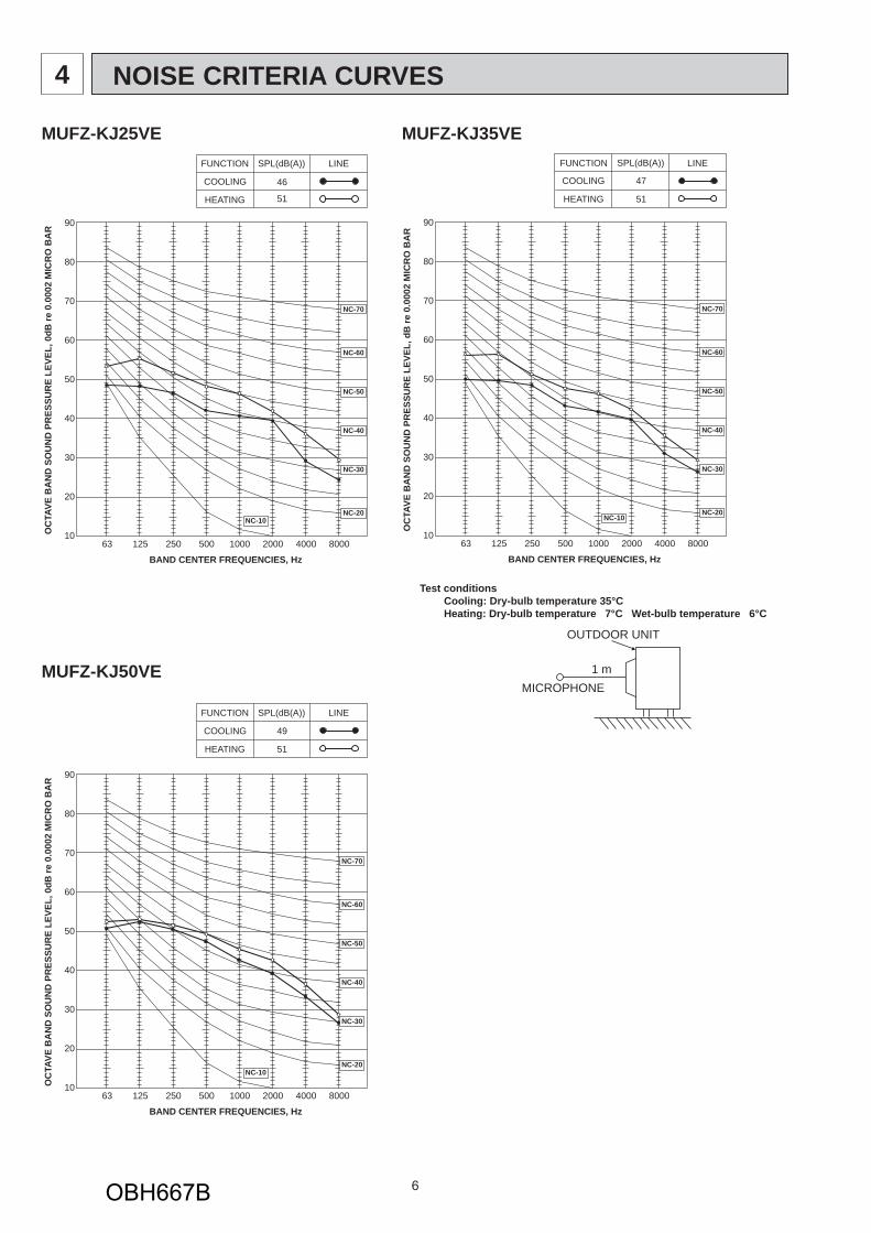
NOTE: Test conditions are based on ISO 5151. Cooling: Indoor Dry-bulb temperature 27°C Wet-bulb temperature 19°C Outdoor Dry-bulb temperature 35°C Heating: Indoor Dry-bulb temperature 20°C Outdoor Dry-bulb temperature 7°C Wet-bulb temperature 6°C Refrigerant piping length (one way): 5 m 1 Measured under rated operating frequency.
SPECIFICATION3
OBH667B
5
Specifi cations and rated conditions of main electric partsModel
Item MUFZ-KJ25VE MUFZ-KJ35VE
Smoothing capacitor (C61, C62) 600 μF/ 620 μF 420 V
Refrigerant piping length (one way) 7 m 10 m 15 m 20 m 25 m 30 m
MUFZ-KJ50 1,500 0 60 160 260 360 460Calculation: X g = 20 g/m × (Refrigerant piping length (m) – 7)
OBH667B
12
PERFORMANCE CURVES8
The standard specifications apply only to the operation of the air conditioner under normal conditions. Since operating condi-tions vary according to the areas where these units are installed, the following information has been provided to clarify the operating characteristics of the air conditioner under the conditions indicated by the performance curve.(1) GUARANTEED VOLTAGE
198 ~ 264 V, 50 Hz(2) AIR FLOW
Air flow should be set at MAX.(3) MAIN READINGS
(1) Indoor intake air wet-bulb temperature: °C [WB] } Cooling(2) Indoor outlet air wet-bulb temperature: °C [WB](3) Outdoor intake air dry-bulb temperature: °C [DB](4) Total input: W(5) Indoor intake air dry-bulb temperature: °C [DB] } Heating(6) Outdoor intake air wet-bulb temperature: °C [WB](7) Total input: WIndoor air wet and dry bulb temperature difference on the left side of the following chart shows the difference between the indoor intake air wet and dry bulb temperature and the indoor outlet air wet and dry bulb temperature for your reference at service.
How to measure the indoor air wet and dry bulb temperature difference1. Attach at least 2 sets of wet and dry bulb thermometers to the indoor air intake as shown in the figure, and at least 2 sets
of wet and dry bulb thermometers to the indoor air outlet. The thermometers must be attached to the position where air speed is high.
2. Attach at least 2 sets of wet and dry bulb thermometers to the outdoor air intake. Cover the thermometers to prevent direct rays of the sun.3. Check that the air filter is cleaned.4. Open windows and doors of room.5. Press the EMERGENCY OPERATION switch once (twice) to start the EMERGENCY COOL (HEAT) MODE.6. When system stabilizes after more than 15 minutes, measure temperature and take an average temperature.7. 10 minutes later, measure temperature again and check that the temperature does not change.
MUFZ-KJ25VEMUFZ-KJ35VEMUFZ-KJ50VE
INDOOR UNIT OUTDOOR UNIT
Wet and dry bulbthermometers FRONT VIEW
Wet and dry bulbthermometers BACK VIEW
Cooling capacity (at Rated frequency)
0.9
1.0
1.1
1.2
1.3
1.4
1.5
-10 -5 0 5 10 15 20 25 30 35 40 45
Outdoor intake air Dry-bulb temperature(°C)
Cap
acity
cor
rect
ion
fact
ors
26
24
2018
22
Indoor intake air Wet-bulbtemperature( )
MU
FZ-K
J35V
E
MU
FZ-K
J25V
E
Indo
or a
ir W
et-b
ulb
tem
pera
ture
diffe
renc
e (°
C)
8.5
7.9
7.2
6.6
6.0
5.4
4.8
12.9
11.8
10.8
9.8
8.8
7.9
7.0
14.6
13.4
12.2
11.0
9.9
8.9
7.8
MU
FZ-K
J50V
E
8-1. CAPACITY AND INPUT CURVES
OBH667B
13
NOTE: The above broken lines are for the heating operation without any frost and defrost operation.
0.8
0.9
1.0
1.1
1.2
1.3
-10 -5 0 5 10 15 20 25 30 35 40 45
Outdoor intake air Dry-bulb temperature (°C)
Inpu
t cor
rect
ion
fact
ors
26 24 222018
Indoor intake air Wet-bulbtemperature( )In
door
air
Wet
-bul
b te
mpe
ratu
redi
ffere
nce
(°C
)
7.2
6.6
6.0
5.4
4.8
4.2
10.8
9.8
8.8
7.9
7.0
6.1
MU
FZ-K
J35V
E
12.2
11.0
9.9
8.9
7.8
6.8
MU
FZ-K
J50V
E
MU
FZ-K
J25V
ETotal input (Cooling : at Rated frequency)
Indo
or a
ir D
ry-b
ulb
tem
pera
ture
diffe
renc
e (°
C)
22.921.219.417.615.914.112.310.68.87.1
MU
FZ-K
J25V
E
29.026.824.522.320.117.815.613.411.18.9
MU
FZ-K
J35V
E
28.025.923.721.619.417.215.112.910.88.6
MU
FZ-K
J50V
E
Outdoor intake air Wet-bulb temperature (°C) -15 -10 -5 0 5 10 15
0.40.50.60.70.80.91.01.11.21.3
Heating capacity (at Rated frequency)
Cap
acity
cor
rect
ion
fact
or
152026
Indoor intake air D
ry-bulb temperature ( )
Indo
or a
ir D
ry-b
ulb
tem
pera
ture
diffe
renc
e (°
C)
22.921.219.417.615.914.112.310.68.87.1
MU
FZ-K
J25V
E
29.026.824.522.320.117.815.613.411.18.9
MU
FZ-K
J35V
E
28.025.923.721.619.417.215.112.910.88.6
MU
FZ-K
J50V
E
Outdoor intake air Wet-bulb temperature (°C) -15 -10 -5 0 5 10 15
0.40.50.60.70.80.91.01.11.21.3
Total input (Heating : at Rated frequency)
Inpu
t cor
rect
ion
fact
or
152026
Indoor intake air Dry-bulb temperature ( )
OBH667B
14
8-2. CAPACITY AND INPUT CORRECTION BY OPERATIONAL FREQUENCY OF COMPRESSOR
0 50 100
0.5
1.0
1.5
0 50 100
0.5
1.0
1.5
0 50 100
0.5
1.0
1.5
0 50 100
1
2
3
0 50 100 150
0.5
1.0
1.5
2.0
0 50 100 150
1
2
3
0 50 100 150
0.5
1.0
1.5
2.0
0 50 100 150
1
2
3
MUFZ-KJ25VE
MUFZ-KJ35VE
Correction of Cooling capacity
The operational frequencyof compressor (Hz)
Cap
acity
corr
ectio
nfa
ctor
s
Correction of Cooling input
The operational frequencyof compressor (Hz)
Inpu
tcor
rect
ion
fact
ors
Correction of Heating capacity
The operational frequencyof compressor (Hz)
Cap
acity
corr
ectio
nfa
ctor
s
Correction of Heating input
The operational frequencyof compressor (Hz)
Inpu
tcor
rect
ion
fact
ors
Correction of Cooling capacity
The operational frequencyof compressor (Hz)
Cap
acity
corr
ectio
nfa
ctor
s
Correction of Cooling input
The operational frequencyof compressor (Hz)
Inpu
tcor
rect
ion
fact
ors
Correction of Heating capacity
The operational frequencyof compressor (Hz)
Cap
acity
corr
ectio
nfa
ctor
s Correction of Heating input
The operational frequencyof compressor (Hz)
Inpu
tcor
rect
ion
fact
ors
Correction of Cooling capacity
Cap
acity
cor
rect
ion
fact
ors
Correction of Cooling input
Inpu
t cor
rect
ion
fact
ors
Correction of Heating capacity
Cap
acity
cor
rect
ion
fact
ors
MUFZ-KJ50VECorrection of Heating input
Cap
acity
cor
rect
ion
fact
ors
The operational frequencyof compressor (Hz)
The operational frequencyof compressor (Hz)
The operational frequencyof compressor (Hz)
The operational frequencyof compressor (Hz)
0 50 100
0.5
1.0
1.5
2.0
0 50 100
0.5
1.0
1.5
2.0
0 50 100 150
0.5
1.0
1.5
2.0
0 50 100 150
0.5
1.0
1.5
2.0
8-3. HOW TO OPERATE FIXED-FREQUENCY OPERATION<Test run operation>1. Press EMERGENCY OPERATION switch to start COOL or HEAT mode (COOL: Press once, HEAT: Press twice).2. Test run operation starts and continues to operate for 30 minutes.3. Compressor operates at rated frequency in COOL mode or 58 Hz in HEAT mode.4. Indoor fan operates at High speed.5. After 30 minutes, test run operation finishes and EMERGENCY OPERATION starts (operation frequency of compressor varies).6. To cancel test run operation (EMERGENCY OPERATION), press EMERGENCY OPERATION switch or any button on
COOL operation Both indoor and outdoor unit are under the same temperature/humidity condition.
Operation: TEST RUN OPERATION (Refer to 8-3.)
8-4. OUTDOOR LOW PRESSURE AND OUTDOOR UNIT CURRENTDry-bulb temperature (°C) Relative humidity (%)
20 5025 6030 70
NOTE: The unit of pressure has been changed to MPa on the international system of units (SI unit system)The conversion factor is: 1 (MPa [Gauge]) = 10.2 (kgf/cm2 [Gauge])
15 20 25 30 351.5
2.0
2.5
3.0
15 20 25 30 352.5
3.0
3.5
4.0
4.5
Ambient temperature (°C)Ambient humidity(%)
50 60 70 50 60 70 50 60 70
Out
door
curre
nt(A
)
Ambient temperature (°C)Ambient humidity(%)
Out
door
curre
nt(A
)
MUFZ-KJ35VEMUFZ-KJ25VEOutdoor unit current
15 20 25 30 353
4
5
6
7
8MUFZ-KJ50VE
Ambient temperature (°C)Ambient humidity(%)
Out
door
curre
nt(A
)
0 5 10 15 20 252.5
3.0
3.5
4.0
4.5
0 5 10 15 20 254
5
6
7
8
9
0 5 10 15 20 254.0
4.5
5.0
5.5
6.0
Ambient temperature (°C)
Out
door
curre
nt(A
)
MUFZ-KJ35VEMUFZ-KJ25VEOutdoor unit current
MUFZ-KJ50VE
Ambient temperature (°C)
Out
door
curre
nt(A
)
Ambient temperature (°C)
Out
door
curre
nt(A
)
Condition:
Operation: Test run operation (Refer to 8-3.)
HEAT operationIndoor Outdoor
Dry bulb temperature (°C) 20.0 2 7 15 20.0Wet bulb temperature (°C) 14.5 1 6 12 14.5
OBH667B
16
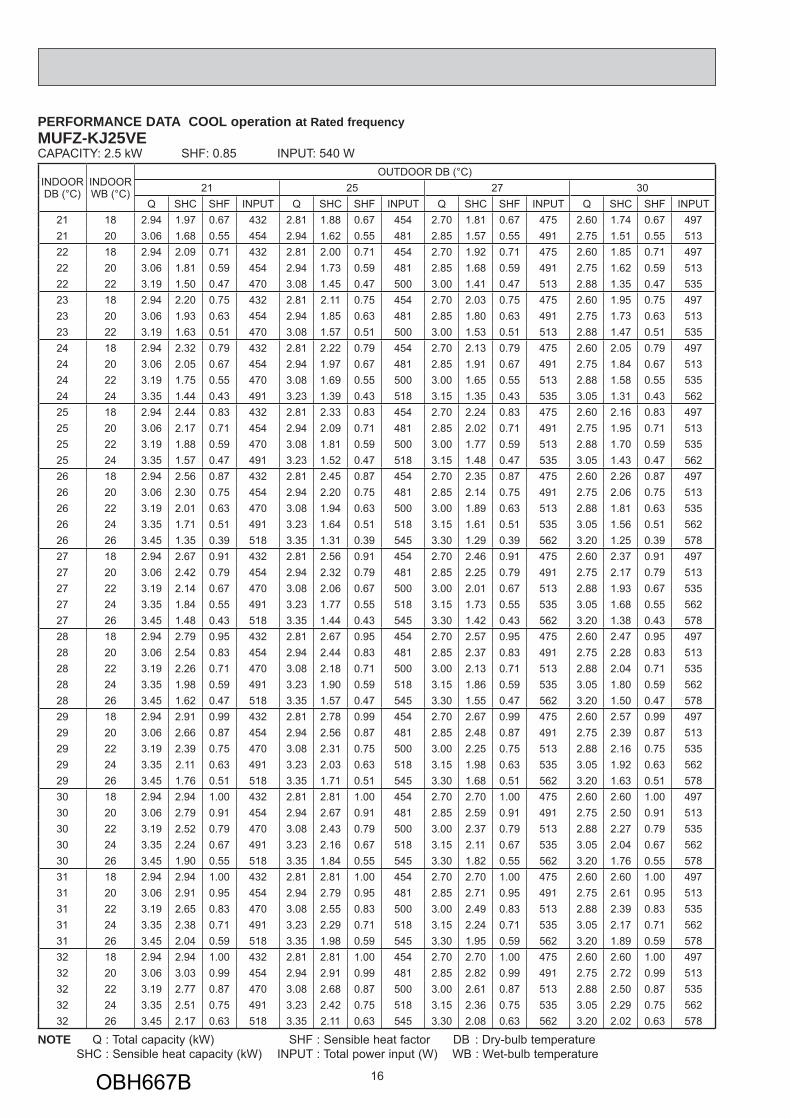
PERFORMANCE DATA COOL operation at Rated frequencyMUFZ-KJ25VE CAPACITY: 2.5 kW SHF: 0.85 INPUT: 540 W
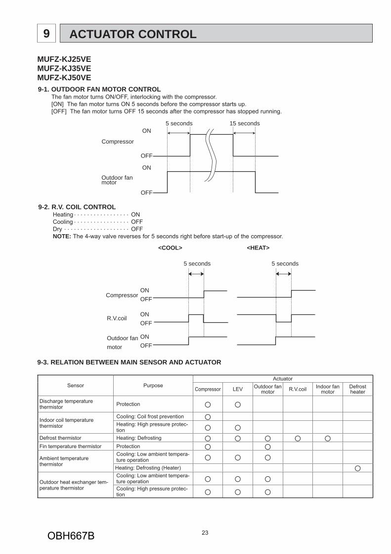
9-1. OUTDOOR FAN MOTOR CONTROLThe fan motor turns ON/OFF, interlocking with the compressor.[ON] The fan motor turns ON 5 seconds before the compressor starts up.[OFF] The fan motor turns OFF 15 seconds after the compressor has stopped running.
9-3. RELATION BETWEEN MAIN SENSOR AND ACTUATOR
Sensor PurposeActuator
Compressor LEV Outdoor fan motor R.V.coil Indoor fan
motorDefrost heater
Discharge temperature thermistor Protection ○ ○Indoor coil temperature thermistor
Cooling: Coil frost prevention ○Heating: High pressure protec-tion ○ ○
Defrost thermistor Heating: Defrosting ○ ○ ○ ○ ○Fin temperature thermistor Protection ○ ○Ambient temperature thermistor
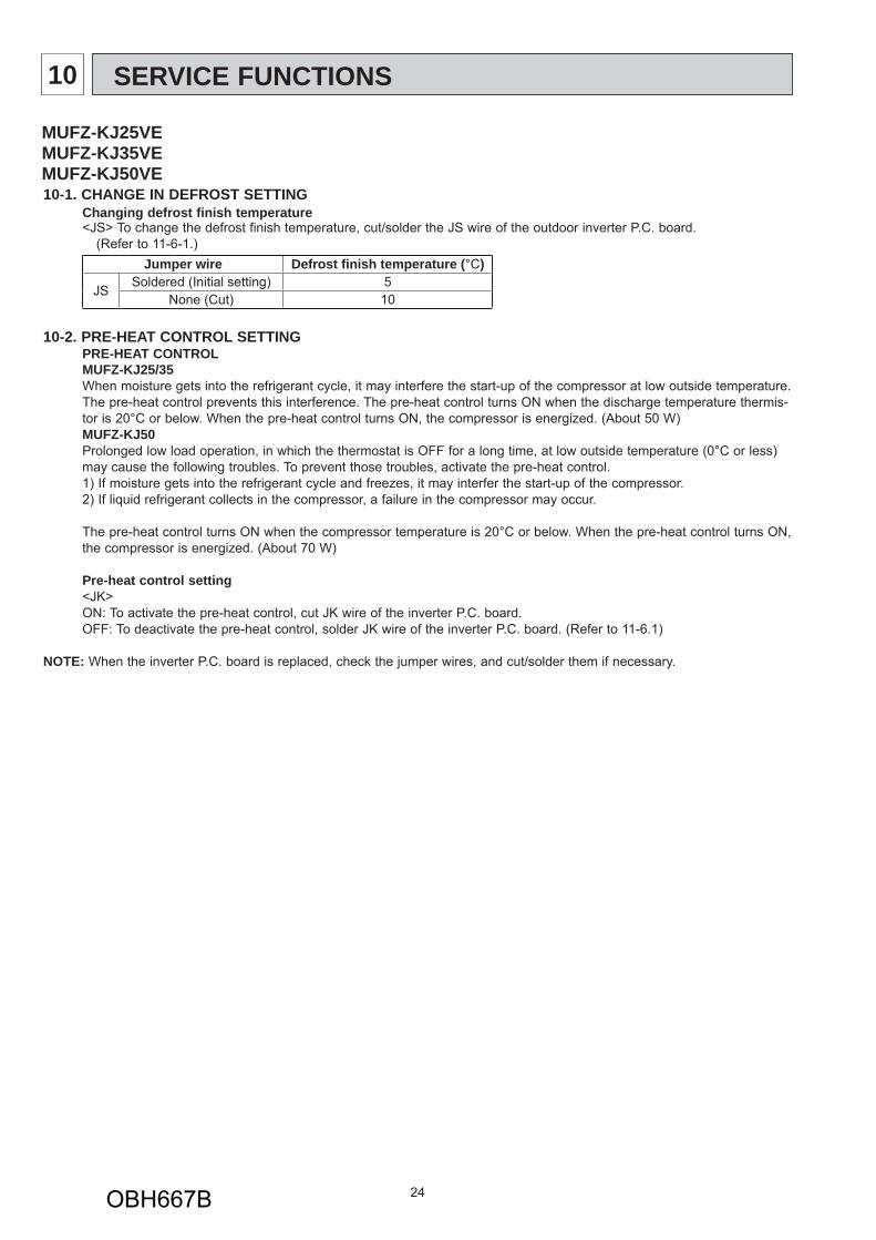
10-1. CHANGE IN DEFROST SETTING Changing defrost finish temperature <JS> To change the defrost finish temperature, cut/solder the JS wire of the outdoor inverter P.C. board. (Refer to 11-6-1.)
Jumper wire Defrost fi nish temperature (°C)
JSSoldered (Initial setting) 5
None (Cut) 10
10-2. PRE-HEAT CONTROL SETTINGPRE-HEAT CONTROLMUFZ-KJ25/35When moisture gets into the refrigerant cycle, it may interfere the start-up of the compressor at low outside temperature. The pre-heat control prevents this interference. The pre-heat control turns ON when the discharge temperature thermis-tor is 20°C or below. When the pre-heat control turns ON, the compressor is energized. (About 50 W)MUFZ-KJ50Prolonged low load operation, in which the thermostat is OFF for a long time, at low outside temperature (0°C or less) may cause the following troubles. To prevent those troubles, activate the pre-heat control. 1) If moisture gets into the refrigerant cycle and freezes, it may interfer the start-up of the compressor.2) If liquid refrigerant collects in the compressor, a failure in the compressor may occur.
The pre-heat control turns ON when the compressor temperature is 20°C or below. When the pre-heat control turns ON, the compressor is energized. (About 70 W)
Pre-heat control setting<JK>ON: To activate the pre-heat control, cut JK wire of the inverter P.C. board. OFF: To deactivate the pre-heat control, solder JK wire of the inverter P.C. board. (Refer to 11-6.1)
NOTE: When the inverter P.C. board is replaced, check the jumper wires, and cut/solder them if necessary.
MUFZ-KJ25VE MUFZ-KJ35VEMUFZ-KJ50VE
OBH667B
25
11-1. CAUTIONS ON TROUBLESHOOTING1. Before troubleshooting, check the following
1) Check the power supply voltage.2) Check the indoor/outdoor connecting wire for miswiring.
2. Take care of the following during servicing1) Before servicing the air conditioner, be sure to turn OFF the main unit first with the remote controller, and then after
confirming the horizontal vane is closed, turn OFF the breaker and/or disconnect the power plug.2) Be sure to turn OFF the power supply before removing the front panel, the cabinet, the top panel, and the electronic
control P.C. board.3) When removing the electrical parts, be careful of the residual voltage of smoothing capacitor. 4) When removing the electronic control P.C. board, hold the edge of the board with care NOT to apply stress on the
components.5) When connecting or disconnecting the connectors, hold the housing of the connector. DO NOT pull the lead wires.
TROUBLESHOOTING11
3. Troubleshooting procedure1) Check if the OPERATION INDICATOR lamp on the indoor unit is flashing on and off to indicate an abnormality. To make sure, check how many times the OPERATION INDICATOR lamp is flashing on and off before starting serv-
ice work.2) Before servicing, check that the connector and terminal are connected properly.3) When the electronic control P.C. board seems to be defective, check the copper foil pattern for disconnection and the
components for bursting and discoloration.4) Refer to 11-2 and 11-3.
Lead wiring Housing point
<Incorrect> <Correct>
MUFZ-KJ25VE MUFZ-KJ35VEMUFZ-KJ50VE
OBH667B
26
Outline of the functionThis air conditioner can memorize the abnormal condition which has occurred once.Even though LED indication listed on the troubleshooting check table (11-3.) disappears, the memorized failure details can be recalled.
11-2. FAILURE MODE RECALL FUNCTION
1. Flow chart of failure mode recall function for the indoor/outdoor unit
NOTE: 1. Make sure to release the failure mode recall function after it is set up, otherwise the unit cannot operate properly. 2. If the abnormal condition is not deleted from the memory, the last abnormal condition is kept memorized.
Does the left lamp of the OPERATION INDICATOR lamp on the indoor unit blink at the interval of 0.5 seconds?Blinks: Either indoor or outdoor unit is abnormal. Beep is emit-
ted at the same timing as the blinking of the left lamp of the OPERATION INDICATOR lamp. 2
Indoor unit is normal.But the outdoor unit might be abnormal because there are some abnor-malities that cannot be recalled with this way.Check if the outdoor unit is abnormal according to the detailed outdoor unit failure mode recall function. (Refer to 11-2.2)
No
Yes
The cause of abnormality cannot be found because the abnormality does not recur.
Setting up the failure mode recall functionTurn ON the power supply.<Preparation of the remote controller>
While pressing OPERATION SELECT (MODE) button and TEMP button on the remote controller at the same time, press RESET button. First, release RESET button.
Hold down the other two buttons for another 3 seconds. Make sure that the indicators on the LCD screen shown in the right fi gure are all displayed. Then release the but-tons.
Press OPERATE/STOP (ON/OFF) button of the remote controller (the set temperature is displayed) with the remote controller headed towards the indoor unit. 1
Judgment of indoor/outdoor abnormalityBefore blinking, does the left lamp of the OPERATION INDI-CATOR lamp stay ON for 3 seconds?Stays ON for 3 seconds (without beep): The outdoor unit is abnormal.
The indoor unit is abnormal.Check the blinking pattern, and identify the abnormal point by referring to the indoor unit failure mode table. (Refer to indoor unit service manual.)Make sure to check at least two consecutive blinking cycles. 2
Releasing the failure mode recall functionRelease the failure mode recall function by the following procedures.Turn OFF the power supply and turn it ON again.Press RESET button of the remote controller.
Repair the failure parts.
Deleting the memorized abnormal condition After repairing the unit, recall the failure mode again according to "Setting up the failure mode recall function" mentioned above. Press OPERATE/STOP (ON/OFF) button of the remote controller (the set temperature is displayed) with the remote controller headed towards the indoor unit. Press EMERGENCY OPERATION switch so that the memorized abnormal condition is deleted. 4 Release the failure mode recall function according to "Releasing the failure mode recall function" mentioned above.
Operational procedure
Yes (Blinks)
No (OFF)
1. Regardless of normal or abnormal condition, a short beep is emitted once the signal is received.
2. Blinking pattern when the indoor unit is abnormal:
3.Blinking pattern when the outdoor unit is abnormal:
ONOFF
BeepsRepeated cycle Repeated cycle
ONOFF
No beep BeepsRepeated cycle
2.5-second OFFBlinking at 0.5-second interval
2.5-second OFF 3-second ONBlinking at 0.5-second interval
BeepsRepeated cycle
2.5-second OFFBlinking at 0.5-second interval
No beep BeepsRepeated cycle
2.5-second OFF 3-second ONBlinking at 0.5-second interval
Repeated cycle
Beeps
AM PM AM PM
NOTE: It takes up to 1 minute to indicate the outdoor unit abnormality. Even if the OPERATION INDICATOR lamp is not lighting, keep checking
at least 1 minute or longer.
4 The information regarding whether the connected outdoor unit is a low-standby-power model or a non-low-standby-power model will also be initialized.
(Default= compatible with a low-standby-power model)
The outdoor unit is abnormal.Check the blinking pattern, and identify the abnormal point by referring to the outdoor unit failure mode table. (Refer to 11-2.3)Make sure to check at least two consecutive blinking cycles. 3
OBH667B
27
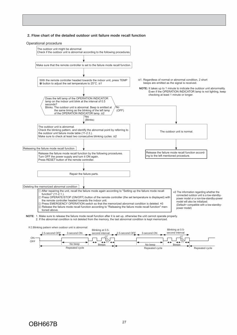
2. Flow chart of the detailed outdoor unit failure mode recall function
2.Blinking pattern when outdoor unit is abnormal:
ONOFF
No beep BeepsRepeated cycle
2.5-second OFF 3-second ONBlinking at 0.5-second interval
No beep BeepsRepeated cycle
2.5-second OFF 3-second ONBlinking at 0.5-second interval
Repeated cycle
Does the left lamp of the OPERATION INDICATOR lamp on the indoor unit blink at the interval of 0.5 seconds?Blinks: The outdoor unit is abnormal. Beep is emitted at
the same timing as the blinking of the left lamp of the OPERATION INDICATOR lamp. 2
Yes (Blinks)
No (OFF)
The outdoor unit might be abnormal.Check if the outdoor unit is abnormal according to the following procedures.
Operational procedure
Make sure that the remote controller is set to the failure mode recall function.
With the remote controller headed towards the indoor unit, press TEMP button to adjust the set temperature to 25°C. 1
1. Regardless of normal or abnormal condition, 2 short beeps are emitted as the signal is received.
The outdoor unit is abnormal.Check the blinking pattern, and identify the abnormal point by referring to the outdoor unit failure mode table (11-2.3.).Make sure to check at least two consecutive blinking cycles. 2
Releasing the failure mode recall function
Release the failure mode recall function by the following procedures.Turn OFF the power supply and turn it ON again.Press RESET button of the remote controller.
Repair the failure parts.
The outdoor unit is normal.
Release the failure mode recall function accord-ing to the left mentioned procedure.
Deleting the memorized abnormal condition After repairing the unit, recall the failure mode again according to "Setting up the failure mode recall function" (11-2.1.). Press OPERATE/STOP (ON/OFF) button of the remote controller (the set temperature is displayed) with the remote controller headed towards the indoor unit. Press EMERGENCY OPERATION switch so that the memorized abnormal condition is deleted. 3 Release the failure mode recall function according to "Releasing the failure mode recall function" men-tioned above.
NOTE: 1. Make sure to release the failure mode recall function after it is set up, otherwise the unit cannot operate properly. 2. If the abnormal condition is not deleted from the memory, the last abnormal condition is kept memorized.
3 The information regarding whether the connected outdoor unit is a low-standby-
power model or a non-low-standby-power model will also be initialized.
(Default= compatible with a low-standby-power model)
NOTE: It takes up to 1 minute to indicate the outdoor unit abnormality. Even if the OPERATION INDICATOR lamp is not lighting, keep
checking at least 1 minute or longer.
OBH667B
28
3. Outdoor unit failure mode tableLeft lamp
of the OPERATION INDICATOR
lamp(Indoor unit)
Abnormal point (Failure mode/protection)
LED indication(Outdoor P.C. board) Condition Remedy
Indoor/outdoor unit failure
mode recall function
Outdoor unit failure mode
recall function
OFF None (Normal) — — — — —1-time fl ash 2.5 seconds OFF
Indoor/outdoor communication, receiving error
—Any signals from the inverter P.C. board cannot be received normally for 3 minutes.
•Refer to 11-5. How to check miswiring and serial signal error. ○ ○Indoor/outdoor
communication, receiving error
—Although the inverter P.C. board sends signal "0", signal "1" has been received 30 consecutive times.
•Refer to 11-5. How to check miswiring and serial signal error.
2-time fl ash 2.5 seconds OFF
Outdoor power system
—
Overcurrent protection cut-out operates 3 consecutive times within 1 minute after the compressor gets started.
Reconnect the connectors.Refer to 11-5. "How to check inverter/compressor".Check the stop valve.
•
•
•○ ○
3-time fl ash2.5 seconds OFF
Discharge temperature thermistor 1-time fl ash every 2.5 seconds
Thermistor shorts or opens during compressor running.
Refer to 11-5."Check of outdoor thermistors". Defective the outdoor thermistors can be identifi ed by checking the blinking pattern of LED.
•
○ ○
Defrost thermistor Fin temperature thermistor 3-time fl ash
2.5 seconds OFF P.C. board temperature thermistor
4-time fl ash2.5 seconds OFF
Ambient temperature thermistor
2-time fl ash 2.5 seconds OFF
Outdoor heat exchanger temperature thermistor —
4-time fl ash 2.5 seconds OFF
Overcurrent 11-time fl ash 2.5 seconds OFF
Large current fl ows into power module (IC700) (KJ25/35)/ IGBT module (IC700) (KJ50).
Reconnect the compressor connector.Refer to 11-5. "How to check inverter/compressor".Check the stop valve.
Reconnect the compressor connector.Refer to 11-5. "How to check inverter/compressor".
•
• — ○5-time fl ash 2.5 seconds OFF
Discharge temperature
—
Temperature of discharge temperature thermistor exceeds 116°C, compressor stops. Compressor can restart if discharge temperature thermistor reads 100°C or less 3 minutes later.
Check the refrigerant circuit and the refrigerant amount.Refer to 11-5. "Check of LEV".
•
• — ○6-time fl ash 2.5 seconds OFF
High pressure
—
Temperature indoor coil thermistor exceeds 70°C in HEAT mode. Temperature defrost thermistor exceeds 70°C in COOL mode.
Check the refrigerant circuit and the refrigerant amount.Check the stop valve.
•
•— ○
7-time fl ash 2.5 seconds OFF
Fin temperature/ P.C. board temperature
7-time fl ash 2.5 seconds OFF
Temperature of fi n temperature thermistor on the inverter P.C. board exceeds 75 ~ 86°C(KJ25/35)/ 75 ~ 80°C (KJ50), or temperature of P.C. board temperature thermistor on the inverter P.C. board exceeds 72 ~ 85°C(KJ25/35)/ 70 ~ 75°C (KJ50).
Check around the outdoor unit.Check the outdoor unit air passage.Refer to 11-5. "Check of outdoor fan motor".
•
•
•— ○
8-time fl ash 2.5 seconds OFF
Outdoor fan motor —
Outdoor fan has stopped 3 times in a row within 30 seconds after outdoor fan start-up.
Refer to 11-5. "Check of outdoor fan motor". Refer to 11-5. "Check of inverter P.C. board".
•
— ○9-time fl ash 2.5 seconds OFF
Nonvolatile memory data 5-time fl ash 2.5 seconds OFF
The interface short circuit occurs in the output of the power module (IC700)(KJ25/35)/ IGBT module (IC700) (KJ50).The compressor winding shorts circuit.
Refer to 11-5. "How to check inverter/compressor".
•
10-time fl ash 2.5 seconds OFF
Discharge temperature
—
Temperature of discharge temperature thermistor has been 50°C or less for 20 minutes.
Refer to 11-5. "Check of LEV".Check the refrigerant circuit and the refrigerant amount.
•
• — ○11-time fl ash 2.5 seconds OFF
Bus-bar voltage (DC) 8-time fl ash 2.5 seconds OFF
Bus-bar voltage of inverter cannot be detected normally.
Refer to 11-5. "How to check inverter/compressor".
•
— ○Each phase current of compressor
9-time fl ash 2.5 seconds OFF
Each phase current of compressor cannot be detected normally.
14-time fl ash 2.5 seconds OFF
Stop valve (Closed valve) 14-time fl ash 2.5 seconds OFF
Closed valve is detected by compressor current.
Check the stop valve.•
○ ○4-way valve/Pipe temperature
16-time fl ash 2.5 seconds OFF
The 4-way valve does not work properly.The indoor coil thermistor detects an abnormal temperature.
Check the 4-way valve.Replace the inverter P.C. board.
•
•
NOTE: Blinking patterns of this mode differ from the ones of TROUBLESHOOTING CHECK TABLE (11-3.).
OBH667B
29
11-3. TROUBLESHOOTING CHECK TABLENo. Symptom LED indication Abnormal point/
Condition Condition Remedy
1
Outdoor unit does not op-erate.
1-time fl ash every 2.5 seconds
Outdoor power sys-tem
Overcurrent protection cut-out operates 3 consecutive times within 1 minute after the compressor gets started.
Reconnect the connector of the compressor.Refer to 11-5. "How to check in-verter/compressor".Check the stop valve.
•
•
•
2Outdoor thermistors Discharge temperature thermistor, fi n temperature thermistor,
defrost thermistor, P.C. board temperature thermistor, outdoor heat exchanger temperature thermistor or ambient tempera-ture thermistor shorts or opens during compressor running.
Refer to 11-5. "Check of outdoor thermistors".
•
3Outdoor control sys-tem
Nonvolatile memory data cannot be read properly.
(POWER lamp of the indoor unit lights up or fl ashes 7-time.)
Replace the inverter P.C. board. •
4
6-time fl ash 2.5 seconds OFF
Serial signal The communication fails between the indoor and outdoor unit for 3 minutes.
Check connection between the in-verter P.C. board and the relay P.C. board. (KJ50)Refer to 11-5. "How to check miswiring and serial signal error.
•
•
5 11-time fl ash 2.5 seconds OFF
Stop valve/ Closed valve
Closed valve is detected by compressor current. Check the stop valve. •
614-time fl ash 2.5 seconds OFF
Outdoor unit(Other abnormality)
Outdoor unit is defective. Refer to 11-2.2. "Flow chart of the detailed outdoor unit failure mode recall function".
•
716-time fl ash 2.5 seconds OFF
4-way valve/Pipe temperature
The 4-way valve does not work properly.The indoor coil thermistor detects an abnormal temperature.
Refer to 11-5. "Check of R.V. coil".Replace the inverter P.C. board.
•
•
8
'Outdoor unit stops and restarts 3 minutes later' is repeated.
2-time fl ash 2.5 seconds OFF
Overcurrent protec-tion
Large current fl ows into power module (IC700)(KJ25/35)/IGBT module (IC700) (KJ50).
Reconnect the connector of the compressor.Refer to 11-5. "How to check in-verter/compressor".Check the stop valve.
•
•
•
93-time fl ash 2.5 seconds OFF
Discharge tempera-ture overheat pro-tection
Temperature of discharge temperature thermistor exceeds 116°C, compressor stops. Compressor can restart if discharge temperature thermistor reads 100°C or less 3 minutes later.
Check the refrigerant circuit and the refrigerant amount.Refer to 11-5. "Check of LEV".
•
•
104-time fl ash 2.5 seconds OFF
Fin temperature /P.C. board tem-perature thermistor overheat protection
Temperature of fi n temperature thermistor on the heat sink ex-ceeds 75 ~ 86°C (KJ25/35)/75 ~ 80°C(KJ50) or temperature of P.C. board temperature thermistor on the inverter P.C.board exceeds 72 ~ 85°C(KJ25/35)/70 ~ 75°C(KJ50).
Check around the outdoor unit.Check the outdoor unit air passage.Refer to 11-5. "Check of outdoor fan motor".
•••
115-time fl ash 2.5 seconds OFF
High pressure pro-tection
Indoor coil thermistor exceeds 70°C in HEAT mode. Defrost thermistor exceeds 70°C in COOL mode.
Check the refrigerant circuit and the refrigerant amount.Check the stop valve.
•
•
128-time fl ash 2.5 seconds OFF
Compressor syn-chronous abnormal-ity
The waveform of compressor current is distorted. Reconnect the connector of the compressor.Refer to 11-5. "How to check in-verter/compressor".
•
•
1310-time fl ash 2.5 seconds OFF
Outdoor fan motor Outdoor fan has stopped 3 times in a row within 30 seconds after outdoor fan start-up.
Refer to 11-5. "Check of outdoor fan motor.Refer to 11-5. "Check of inverter P.C. board.
•
•
14 12-time fl ash 2.5 seconds OFF
Each phase current of compressor
Each phase current of compressor cannot be detected nor-mally.
Refer to 11-5. "How to check in-verter/compressor".
•
15
13-time fl ash 2.5 seconds OFF
Bus-bar voltage (DC)
Bus-bar voltage of inverter cannot be detected normally. It occurs with following case. Instantaneous power voltage drop. (Short time power failure) (KJ50)Refer to 11-5. "Check of power supply". (KJ50)Refer to 11-5. "How to check in-verter/compressor".
•
•
•
16
Outdoor unit operates.
1-time fl ash 2.5 seconds OFF
Frequency drop by current protection
KJ25/35 When the input current exceeds approximately 10A (KJ25)/10.5A (KJ35), compressor frequency lowers.
The unit is normal, but check the following. Check if the indoor fi lters are clogged.Check if the refrigerant is short.Check if the indoor/outdoor unit air circulation is short cycled.
•
••
KJ50 Current from power outlet is nearing breaker ca-pacity.
17
3-time fl ash 2.5 seconds OFF
Frequency drop by high pressure pro-tection
Temperature of indoor coil thermistor exceeds 55°C in HEAT mode, compressor frequency lowers.
Frequency drop by defrosting in COOL mode
Indoor coil thermistor reads 8°C or less in COOL mode, com-pressor frequency lowers.
18
4-time fl ash 2.5 seconds OFF
Frequency drop by discharge tempera-ture protection
Temperature of discharge temperature thermistor exceeds 111°C, compressor frequency lowers.
Check the refrigerant circuit and the refrigerant amount.Refer to 11-5. "Check of LEV".Refer to 11-5. "Check of outdoor thermistors".
•
••
195-time fl ash 2.5 seconds OFF
Outside temperature thermistor protec-tion
When the outside temperature thermistor shorts or opens, protective operation without that thermistor is performed.
Refer to 11-5. Check of outdoor thermistors.
•
OBH667B
30
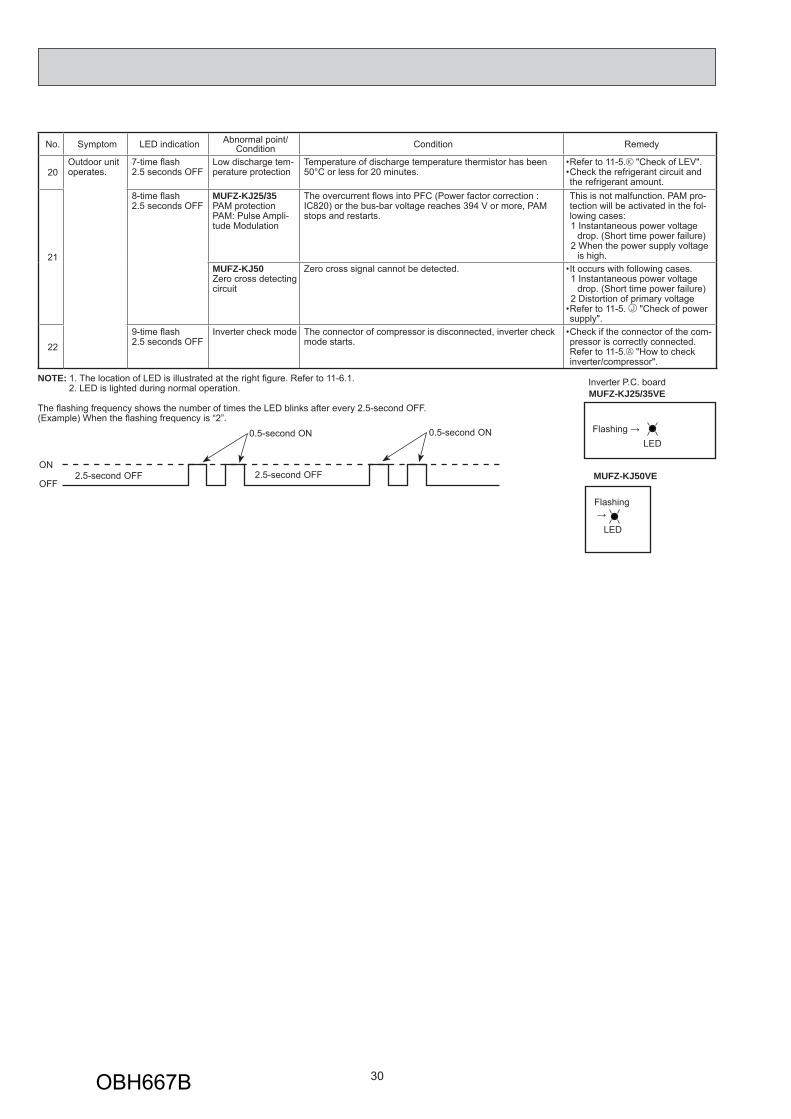
No. Symptom LED indication Abnormal point/ Condition Condition Remedy
20Outdoor unit operates.
7-time fl ash 2.5 seconds OFF
Low discharge tem-perature protection
Temperature of discharge temperature thermistor has been 50°C or less for 20 minutes.
Refer to 11-5. "Check of LEV".Check the refrigerant circuit and the refrigerant amount.
The overcurrent fl ows into PFC (Power factor correction :IC820) or the bus-bar voltage reaches 394 V or more, PAM stops and restarts.
This is not malfunction. PAM pro-tection will be activated in the fol-lowing cases:1 Instantaneous power voltage
drop. (Short time power failure)2 When the power supply voltage
is high. MUFZ-KJ50Zero cross detecting circuit
Zero cross signal cannot be detected. It occurs with following cases.1 Instantaneous power voltage
drop. (Short time power failure)2 Distortion of primary voltageRefer to 11-5. "Check of power supply".
•
•
229-time fl ash 2.5 seconds OFF
Inverter check mode The connector of compressor is disconnected, inverter check mode starts.
Check if the connector of the com-pressor is correctly connected. Refer to 11-5. "How to check inverter/compressor".
•
NOTE: 1. The location of LED is illustrated at the right fi gure. Refer to 11-6.1. 2. LED is lighted during normal operation.
The fl ashing frequency shows the number of times the LED blinks after every 2.5-second OFF.(Example) When the fl ashing frequency is “2”.
ON
OFF2.5-second OFF 2.5-second OFF
0.5-second ON 0.5-second ONLED
Flashing →
MUFZ-KJ50VE
LED→Flashing
MUFZ-KJ25/35VEInverter P.C. board
OBH667B
31
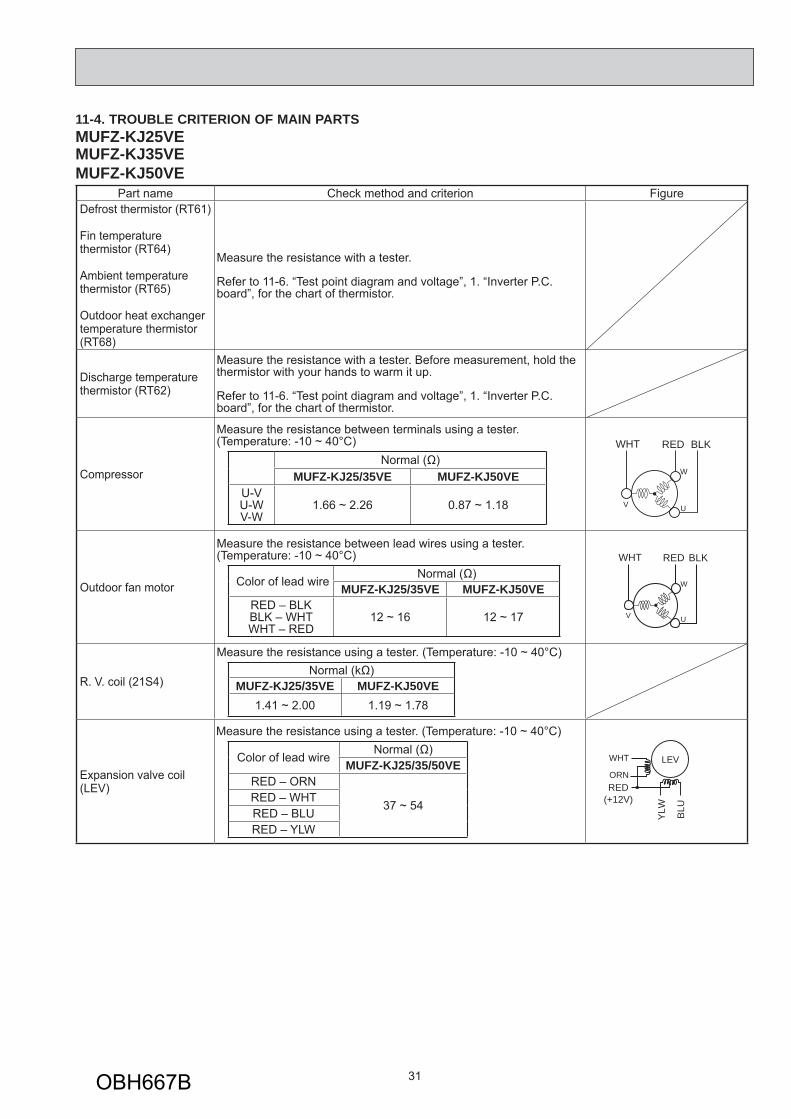
11-4. TROUBLE CRITERION OF MAIN PARTSMUFZ-KJ25VE MUFZ-KJ35VE MUFZ-KJ50VE
Part name Check method and criterion FigureDefrost thermistor (RT61)
Fin temperature thermistor (RT64)
Ambient temperature thermistor (RT65)
Outdoor heat exchanger temperature thermistor (RT68)
Measure the resistance with a tester.
Refer to 11-6. “Test point diagram and voltage”, 1. “Inverter P.C. board”, for the chart of thermistor.
Discharge temperature thermistor (RT62)
Measure the resistance with a tester. Before measurement, hold the thermistor with your hands to warm it up.
Refer to 11-6. “Test point diagram and voltage”, 1. “Inverter P.C. board”, for the chart of thermistor.
Compressor
Measure the resistance between terminals using a tester.(Temperature: -10 ~ 40°C)
Normal (Ω)MUFZ-KJ25/35VE MUFZ-KJ50VE
U-VU-WV-W
1.66 ~ 2.26 0.87 ~ 1.18
Outdoor fan motor
Measure the resistance between lead wires using a tester.(Temperature: -10 ~ 40°C)
Color of lead wire Normal (Ω)MUFZ-KJ25/35VE MUFZ-KJ50VE
RED – BLKBLK – WHTWHT – RED
12 ~ 16 12 ~ 17
R. V. coil (21S4)
Measure the resistance using a tester. (Temperature: -10 ~ 40°C)Normal (kΩ)
MUFZ-KJ25/35VE MUFZ-KJ50VE1.41 ~ 2.00 1.19 ~ 1.78
Expansion valve coil (LEV)
Measure the resistance using a tester. (Temperature: -10 ~ 40°C)
Color of lead wire Normal (Ω)
MUFZ-KJ25/35/50VERED – ORN
37 ~ 54RED – WHTRED – BLURED – YLW
RED(+12V)
YLW BLU
WHT
ORN
LEV
W
UV
WHT RED BLK
W
UV
WHT RED BLK
OBH667B
32
11-5. TROUBLESHOOTING FLOW
A How to check inverter/compressor
Refer to 11-5. “Check of compressor operation time”.Does the compressor operate continuously?
Refer to 11-5. “Check of compressor start failure”.
OK.
No
Yes
Refer to 11-5. “Check of compressor winding”.Is the compressor normal?
Replace the compressor.No
Yes
B Check of open phase
C Check of compressor
● With the connector between the compressor and the power module (IC700)(MUFZ-KJ25/35)/ IGBT module (IC700)(MUFZ-KJ50) disconnected, activate the inverter and check if the inverter is normal by measuring the voltage balance between the terminals.
Output voltage is 50 - 130 V. (The voltage may differ according to the tester.)
<< Operation method>> Start cooling or heating operation by pressing EMERGENCY OPERATION switch on the indoor unit. (TEST RUN OPERA-
TION: Refer to 8-3.)<<Measurement point>> At 3 points BLK (U)-WHT (V) BLK (U)-RED (W) WHT(V)-RED (W)
NOTE: 1. Output voltage varies according to power supply voltage. 2. Measure the voltage by analog type tester. 3. During this check, LED of the inverter P.C. board fl ashes 9 times. (Refer to 11-6.1.)
Measure AC voltage between the lead wires at 3 points.
Are the voltages balanced?
Disconnect the connector between the compressor and the power module (IC700)(MUFZ-KJ25/35)/ IGBT module (IC700)(MUFZ-KJ50).
Replace the inverter P.C. board.
Check the voltage between terminals.
Check the compressor. See 11-5. “Check of compressor”.
NoYes
See 11-5. “Check of open phase”.
OBH667B
33
F Check of compressor start failure
D Check of compressor winding
E Check of compressor operation time
● Disconnect the connector between the compressor and the power module (IC700)(MUFZ-KJ25/35)/ IGBT module (IC700)(MUFZ-KJ50), and measure the resistance between the compressor terminals.
<<Measurement point>> At 3 points BLK-WHT BLK-RED WHT-RED<<Judgement>> Refer to 11-4. 0 [Ω] ················Abnormal [short] Infinite [Ω] ·······Abnormal [open] NOTE: Be sure to zero the ohmmeter before measurement.
Measure the resistance between the lead wires at 3 points.
1Heat the compressor with a drier for about 20 minutes.Do not recover refrigerantgas while heating.
Heating part
● Connect the compressor and activate the inverter. Then measure the time until the inverter stops due to over current.<<Operation method>>Start heating or cooling operation by pressing EMERGENCY OPERATION switch on the indoor unit. (TEST RUN OPERATION: Refer to 8-3.)<<Measurement>>Measure the time from the start of compressor to the stop of compressor due to overcurrent.
After the compressor is heated with a drier, does the compressor start? 1 Replace the compressor.
Compressor start failure. Activate pre-heat control.(Refer to 10-2. "PRE-HEAT CONTROL SETTING")
No
Yes
Does the compressor run for 10 seconds or more after it starts?
Check the refrigerant circuit.Check the stop valve.Yes
No
Confi rm that ~ is normal.•Electrical circuit check
. Contact of the compressor connector
. Output voltage of inverter P.C. board and balance of them (See 11-5. )
. Direct current voltage between DB61(+) and (-)(MUFZ-KJ25/35)/ JP715(+) and JP30(-)(MUFZ-KJ50)on the inverter P.C. board
. Voltage between outdoor terminal block S1-S2
OBH667B
34
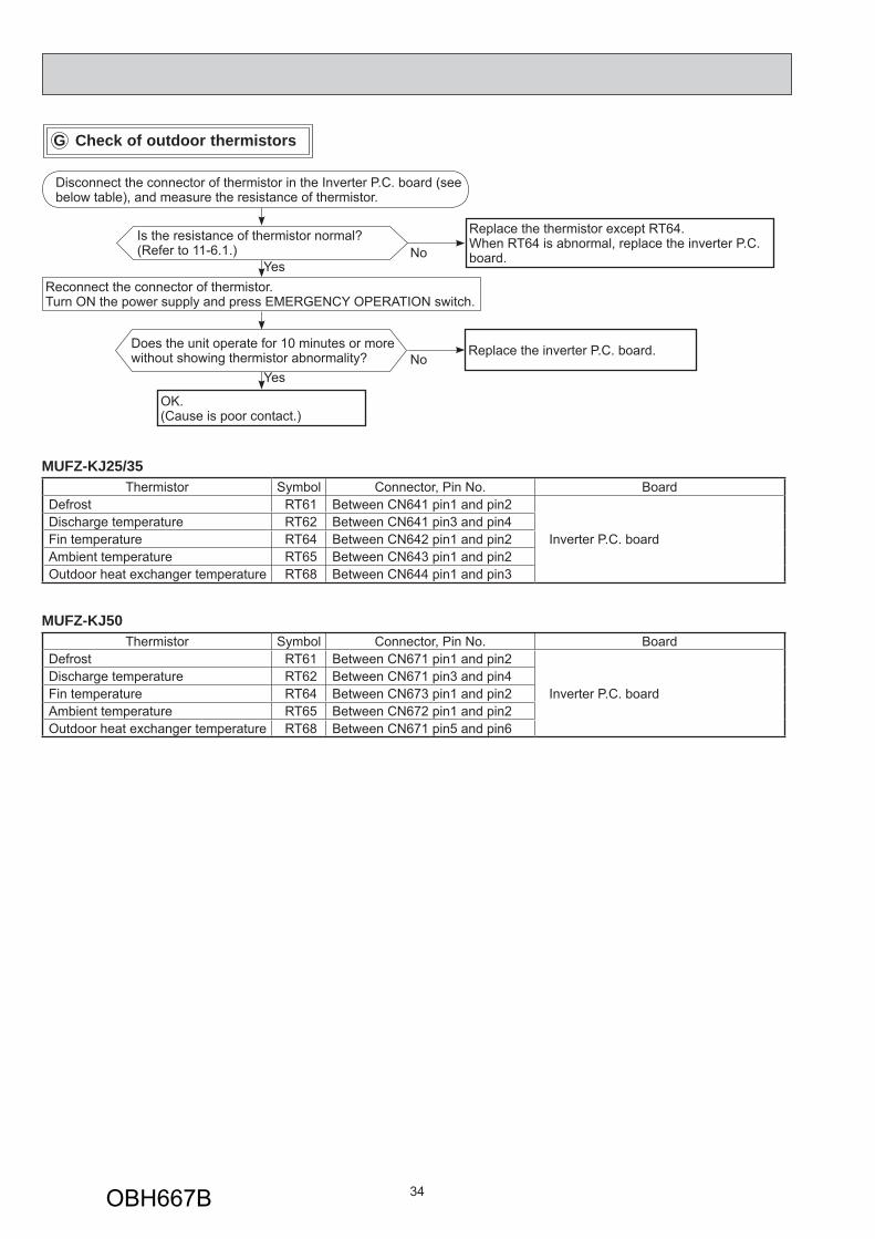
G Check of outdoor thermistors
Replace the thermistor except RT64.When RT64 is abnormal, replace the inverter P.C. board.
Replace the inverter P.C. board.
No
No
Is the resistance of thermistor normal? (Refer to 11-6.1.)
Reconnect the connector of thermistor.Turn ON the power supply and press EMERGENCY OPERATION switch.
Does the unit operate for 10 minutes or more without showing thermistor abnormality?
OK.(Cause is poor contact.)
Yes
Yes
Disconnect the connector of thermistor in the Inverter P.C. board (see below table), and measure the resistance of thermistor.
MUFZ-KJ25/35Thermistor Symbol Connector, Pin No. Board
Defrost RT61 Between CN641 pin1 and pin2
Inverter P.C. boardDischarge temperature RT62 Between CN641 pin3 and pin4 Fin temperature RT64 Between CN642 pin1 and pin2 Ambient temperature RT65 Between CN643 pin1 and pin2 Outdoor heat exchanger temperature RT68 Between CN644 pin1 and pin3
MUFZ-KJ50Thermistor Symbol Connector, Pin No. Board
Defrost RT61 Between CN671 pin1 and pin2
Inverter P.C. boardDischarge temperature RT62 Between CN671 pin3 and pin4 Fin temperature RT64 Between CN673 pin1 and pin2 Ambient temperature RT65 Between CN672 pin1 and pin2 Outdoor heat exchanger temperature RT68 Between CN671 pin5 and pin6
OBH667B
35
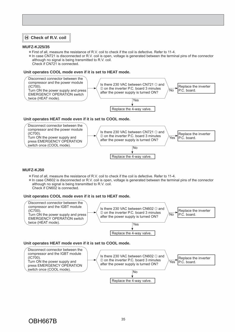
H Check of R.V. coil
First of all, measure the resistance of R.V. coil to check if the coil is defective. Refer to 11-4. In case CN721 is disconnected or R.V. coil is open, voltage is generated between the terminal pins of the connector although no signal is being transmitted to R.V. coil.
Check if CN721 is connected.
Is there 230 VAC between CN721 and on the inverter P.C. board 3 minutes
after the power supply is turned ON? No
Yes
Replace the inverterP.C. board.
Replace the 4-way valve.
Unit operates COOL mode even if it is set to HEAT mode.
Is there 230 VAC between CN721 and on the inverter P.C. board 3 minutes
after the power supply is turned ON? Yes
No
Replace the inverterP.C. board.
Replace the 4-way valve.
Unit operates HEAT mode even if it is set to COOL mode.
Disconnect connector between the compressor and the power module (IC700).Turn ON the power supply and press EMERGENCY OPERATION switch twice (HEAT mode).
Disconnect connector between the compressor and the power module (IC700).Turn ON the power supply and press EMERGENCY OPERATION switch once (COOL mode).
First of all, measure the resistance of R.V. coil to check if the coil is defective. Refer to 11-4. In case CN602 is disconnected or R.V. coil is open, voltage is generated between the terminal pins of the connector although no signal is being transmitted to R.V. coil.
Check if CN602 is connected.
Is there 230 VAC between CN602 and on the inverter P.C. board 3 minutes
after the power supply is turned ON? No
Yes
Replace the inverterP.C. board.
Replace the 4-way valve.
Unit operates COOL mode even if it is set to HEAT mode.
Is there 230 VAC between CN602 and on the inverter P.C. board 3 minutes
after the power supply is turned ON? Yes
No
Replace the inverterP.C. board.
Replace the 4-way valve.
Unit operates HEAT mode even if it is set to COOL mode.
Disconnect connector between the compressor and the IGBT module (IC700).Turn ON the power supply and press EMERGENCY OPERATION switch twice (HEAT mode).
Disconnect connector between the compressor and the IGBT module (IC700).Turn ON the power supply and press EMERGENCY OPERATION switch once (COOL mode).
MUFZ-KJ25/35
MUFZ-KJ50
OBH667B
36
I Check of outdoor fan motor
Is the resistance between each ter-minal of outdoor fan motor normal? (Refer to 11-4.)
Disconnect CN932 from the inverter P.C. board, and turn on the power supply.
Rotate the outdoor fan motor manually and measure the voltage of CN931.Between 1(+) and 5(-)Between 2(+) and 5(-)Between 3(+) and 5(-)
Does the voltage between each terminal become 5 and 0 VDC repeatedly?
Does the outdoor fan motor rotate smoothly?
Replace the outdoor fan motor. Replace the inverter P.C. board.
Yes
Yes
No(Fixed to either 5 or 0 VDC)
No
No
Yes
Disconnect the connectors CN931 and CN932 from the inverter P.C. board.Check the connection between the connector CN931 and CN932.
OBH667B
37
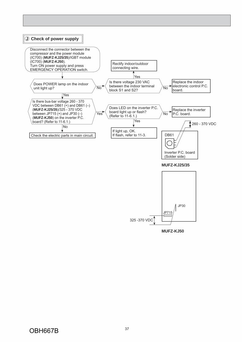
J Check of power supply
Is there voltage 230 VAC between the indoor terminal block S1 and S2? No
YesReplace the indoor electronic control P.C. board.
Rectify indoor/outdoor connecting wire.
Yes
If light up, OK.If fl ash, refer to 11-3.
Does POWER lamp on the indoor unit light up?
Does LED on the inverter P.C. board light up or fl ash?(Refer to 11-6.1.) No
Replace the inverter P.C. board.
Is there bus-bar voltage 260 - 370 VDC between DB61 (+) and DB61 (–) (MUFZ-KJ25/35)/325 - 370 VDC between JP715 (+) and JP30 (–) (MUFZ-KJ50) on the inverter P.C. board? (Refer to 11-6.1.)
No
Check the electric parts in main circuit.
Yes
Yes
No
Disconnect the connector between the compressor and the power module (IC700) (MUFZ-KJ25/35)/IGBT module (IC700) (MUFZ-KJ50).Turn ON power supply and pressEMERGENCY OPERATION switch.
Inverter P.C. board(Solder side)
DB61
260 - 370 VDC
MUFZ-KJ25/35
325 -370 VDC
JP30
JP715
MUFZ-KJ50
OBH667B
38
Press OPERATE/STOP (ON/OFF) button of the remote controller (the set temperature is displayed) with the remote controller headed towards the indoor unit. 1
Expansion valve operates in full-opening direction.
OK
NOTE: After check of LEV, do the undermentioned operations. 1. Turn OFF the power supply and turn it ON again. 2. Press RESET button on the remote controller.
1. Regardless of normal or abnormal condition, a short beep is emitted once the signal is received.
Measure each voltage between connector pins of CN724 on the inverter P.C. board.1. Pin (-) — Pin (+)2. Pin (-) — Pin (+)3. Pin (-) — Pin (+)4. Pin (-) — Pin (+)Is there about 3 - 5 VAC between each?NOTE: Measure the voltage by an analog
tester.
Properly fi x the LEV coil to the expansion valve.
Replace the inverter P.C. board.
Replace the LEV coil.
Replace the expansion valve.
Is LEV coil properly fi xed to the expansion valve?
Does the resistance of LEV coil have the characteristics?(Refer to 11-4.)
Do you hear the expansion valve "click, click·······"?Do you feel the expansion valve vibrate on touching it ?
Turn ON the power supply.<Preparation of the remote controller>
While pressing both OPERATION SELECT (MODE) button and TEMP button on the remote controller at the same time, press RESET button. First, release RESET button.
Hold down the other two buttons for another 3 sec-onds. Make sure that the indicators on the LCD screen shown in the right fi gure are all displayed. Then re-lease the buttons.
Yes
No
No
Yes
NoYes
No
Yes
K Check of LEV (Expansion valve)
AM PM AM PM
OBH667B
39
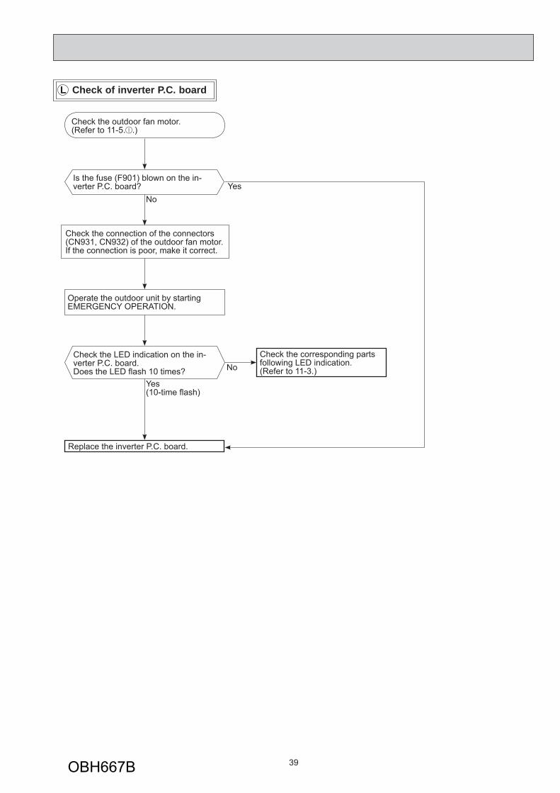
Check the outdoor fan motor. (Refer to 11-5. .)
Is the fuse (F901) blown on the in-verter P.C. board?
Check the connection of the connectors (CN931, CN932) of the outdoor fan motor. If the connection is poor, make it correct.
Operate the outdoor unit by starting EMERGENCY OPERATION.
Check the LED indication on the in-verter P.C. board.Does the LED fl ash 10 times?
Replace the inverter P.C. board.
Check the corresponding parts following LED indication.(Refer to 11-3.)
YesNo
Yes(10-time fl ash)
No
L Check of inverter P.C. board
OBH667B
40
How to check miswiring and serial signal errorM
Turn OFF inverter-controlled lighting equipment.Turn OFF the power supply and then turn it ON again.Press EMERGENCY OPERATION switch.
•••
A
Is serial signal error indicated 6 minutes later?
B
Yes
Reinstall either the unit or the light away from each other.Attach a fi lter on remote control receiving section of the indoor unit.
•
•No
Turn OFF the power supply.
Is there rated voltage in the power supply?
YesNo
Turn ON the power supply.
Check the power supply.
Is there rated voltage between outdoor terminal block S1 and S2?
YesNo
Check the wiring.
Press EMERGENCY OPERATION switch once.
Does the left lamp of OPERATION INDICATOR lamp on the indoor unit light up? <Confi rmation of the power supply to the indoor unit>
YesCorrect the wiring.Is the serial signal error
indicated 6 minutes later?Yes
Is there any miswiring, poor contact or wire dis-connection of the indoor/outdoor connecting wire?
No
Yes
No
A
Is there rated voltage between outdoor terminal block S1 and S2?Yes
Check for miswiring, broken wires, and loose wire connection between the power supply and outdoor terminal block S1 and between the power supply and outdoor terminal block S2.
Wait for 2 or more minutes after the power supply is turned on.Touch S2 and S3 with tester probes and start the emergency operation.
No
Turn the power supply ON.
When the emergency operation starts, does the rated voltage occur for 2 seconds between indoor terminal block S2 and S3?
YesReplace the indoor electronic control P.C. board.Does the left lamp of the OPERA-
TION INDICATOR lamp on the indoor unit blink continuously 6 minutes af-ter the emergency operation starts?
NoDoes the outdoor LED light up?
Yes
Does the outdoor LED blink 6 times?
Yes
Confi rm that the thermostat is OFF and wiring is not loose.
No
Does DC (6V or more) occur between indoor terminal block S2 and S3?
Yes
Replace the outdoor inverter P.C. board. 1No
Turn the power supply OFF.Replace the indoor electronic control P.C. board.
1.Electric charge may remain immediately after the power supply is turned OFF.Perform the procedure after 3 minutes.
Replace the outdoor inverter P.C. board. 1
Yes
No
No
B
MUFZ-KJ25/35
No
Was the indoor unit ever connected to the Multi (MXZ) series and operated (turned on)?
The connection information to the Multi series is stored in the indoor unit. Refer to “Deleting the memorized abnormal condition” described in 11-2.1 to clear the error history. When the error history is being cleared, the connection information also will be initialized. The indoor unit will be compatible with a low-standby-power model after initialization.
OK
Yes
MFZ-KJ25/35VE- E2 , ER2
OBH667B
41
MUFZ-KJ50Turn the power supply OFF.
Is there rated voltage in the power supply?Yes No
Check for incorrect indoor-outdoor connecting wiring.
Check the power supply.
Turn OFF inverter-controlled lighting equipment.Turn OFF the power supply and then turn ON again.Press EMERGENCY OPERATION switch.
•••
A
Is serial signal error indicated 6 minutes later?
B
Yes
Reinstall either the unit or the light away from each other.Attach a fi lter on remote control receiving section of the indoor unit.
•
•No
NOTE: Refer to the indoor unit service manual.
Is there rated voltage between outdoor terminal block S1 and S2?Check for miswiring, broken wires, and loose wire connection between the power supply and outdoor terminal block S1 and between the power supply and outdoor terminal block S2.
Wait for 2 or more minutes after the power supply is turned on.Touch S2 and S3 with tester probes and start the emergency operation.
When the emergency operation starts, does the rated voltage occur for 2 sec-onds between indoor terminal block S2 and S3?
No
Yes
Replace the indoor electronic control P.C. board.
Does the left lamp of the OPERA-TION INDICATOR lamp on the indoor unit blink continuously 6 minutes after the emergency operation starts?
No Does DC (10 V or more) occur between L68A and L68B on the outdoor relay P.C. board?
Yes
Does the outdoor LED blink 6 times?
Yes
Replace the outdoor relay P.C. board. 1
No
Does DC (more than 0 V) occur between indoor terminal block S2 and S3?
Yes
Replace the outdoor inverter P.C. board. 1
No
Turn the power supply OFF.
Start the emergency operation.
No Repair has been completed.
Replace the outdoor inverter P.C. board and the outdoor relay P.C. board. 1
1.Electric charge may remain immediately after the power supply is turned OFF.Perform the procedure after 3 minutes.
Replace the outdoor inverter P.C. board and the outdoor relay P.C. board. 1
Turn the power supply ON.
Does the left lamp of the OPERA-TION INDICATOR lamp on the indoor unit blink continuously 6 minutes after the emergency operation starts?
Yes
No
Replace the indoor electronic control P.C. board.
Yes
Replace the outdoor inverter P.C. board and the outdoor relay P.C. board. 1
Yes
A
B Turn the power supply ON.
No
Was the indoor unit ever connected to the Multi (MXZ) series and operated (turned on)?
The connection information to the Multi series is stored in the indoor unit. Refer to “Deleting the memorized abnormal condition” described in 11-2.1 to clear the error history. When the error history is being cleared, the connection information also will be initialized. The indoor unit will be compatible with a low-standby-power model after initialization.
OK
Yes
No
OBH667B
42
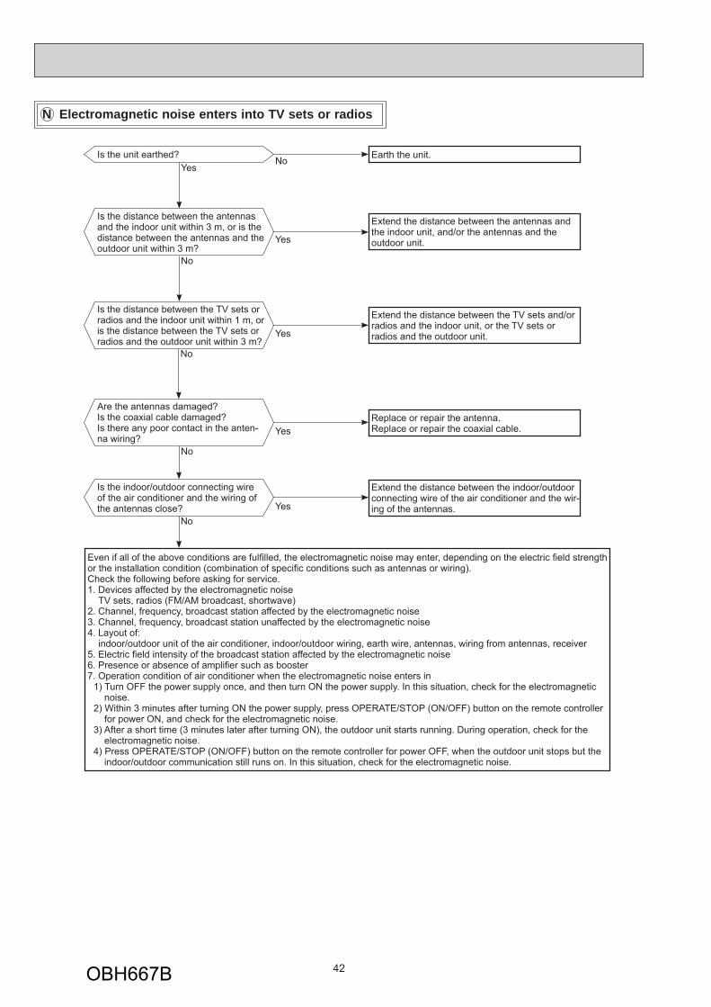
N Electromagnetic noise enters into TV sets or radios
YesIs the unit earthed?
No Earth the unit.
Yes
Is the distance between the antennas and the indoor unit within 3 m, or is the distance between the antennas and the outdoor unit within 3 m?
No
Extend the distance between the antennas and the indoor unit, and/or the antennas and the outdoor unit.
Is the distance between the TV sets or radios and the indoor unit within 1 m, or is the distance between the TV sets or radios and the outdoor unit within 3 m?
Yes
Extend the distance between the TV sets and/or radios and the indoor unit, or the TV sets or radios and the outdoor unit.
Are the antennas damaged?Is the coaxial cable damaged?Is there any poor contact in the anten-na wiring?
Yes
No
No
Replace or repair the antenna.Replace or repair the coaxial cable.
Is the indoor/outdoor connecting wire of the air conditioner and the wiring of the antennas close? Yes
Extend the distance between the indoor/outdoor connecting wire of the air conditioner and the wir-ing of the antennas.
No
Even if all of the above conditions are fulfi lled, the electromagnetic noise may enter, depending on the electric fi eld strength or the installation condition (combination of specifi c conditions such as antennas or wiring).Check the following before asking for service.1. Devices affected by the electromagnetic noise TV sets, radios (FM/AM broadcast, shortwave)2. Channel, frequency, broadcast station affected by the electromagnetic noise3. Channel, frequency, broadcast station unaffected by the electromagnetic noise4. Layout of: indoor/outdoor unit of the air conditioner, indoor/outdoor wiring, earth wire, antennas, wiring from antennas, receiver5. Electric fi eld intensity of the broadcast station affected by the electromagnetic noise6. Presence or absence of amplifi er such as booster7. Operation condition of air conditioner when the electromagnetic noise enters in
1) Turn OFF the power supply once, and then turn ON the power supply. In this situation, check for the electromagnetic noise.
2) Within 3 minutes after turning ON the power supply, press OPERATE/STOP (ON/OFF) button on the remote controller for power ON, and check for the electromagnetic noise.
3) After a short time (3 minutes later after turning ON), the outdoor unit starts running. During operation, check for the electromagnetic noise.
4) Press OPERATE/STOP (ON/OFF) button on the remote controller for power OFF, when the outdoor unit stops but the indoor/outdoor communication still runs on. In this situation, check for the electromagnetic noise.
OBH667B
43
-20 -10 0 10 20 30 400
10
20
30
40
50
60
70
80
90
100
Temperature( )
Defrost thermistor(RT61)Ambient temperature thermistor(RT65)Outdoor heat exchanger temperature thermistor(RT68)
Temperature( )
Discharge temperature thermistor(RT62)
0 10 20 30 40 50 60 70 80 90 100 110 1200
100
200
300
400
500
600
700
0 10 20 30 40 50 60 70 800
20
40
60
80
100
120
140
160
180
200
Temperature( )
Fin temperature thermistor(RT64)
Res
ista
nce(
k )
Res
ista
nce(
k )
Res
ista
nce(
k )
1. Inverter P.C. board
MUFZ-KJ25VE MUFZ-KJ35VE
11-6. TEST POINT DIAGRAM AND VOLTAGE
Fin
tem
pera
ture
ther
mis
tor/R
T64
(CN
642)
Am
bien
t tem
pera
ture
th
erm
isto
r/RT6
5(C
N64
3)
Dis
char
ge te
mpe
ratu
re
ther
mis
tor/R
T62
(CN
641)
Def
rost
ther
mis
tor
/RT6
1(C
N64
1)
DB61260 - 370 VDC
Front side of unit
230 VAC
Smoothing capacitor(C62)
Output to drivecompressor(LDU,LDV,LDW)
(+)(-) Fuse (F701)T3.15AL250V
Smoothing capacitor(C61)
Fuse (F901)T3.15AL250V
R.V.coil(CN721)230 VAC
Jumper wire for changing defrost setting (JS)
Sig
nal o
f out
door
fan
mot
or (C
N93
1)
230 VACO
utdo
or h
eat e
xcha
nger
tem
pera
ture
ther
mis
tor
/RT6
8 (C
N64
4)
Jumper wire for pre-heat control setting (JK)
Fuse (F801)T3.15AL250V
Back side of unit
LEV
con
nect
or (C
N72
4)
Output to drive outdoor fan motor(CN932)
LED
OBH667B
44
MUFZ-KJ50VE
-20 -10 0 10 20 30 400
10
20
30
40
50
60
70
80
90
100
Temperature( )
Defrost thermistor(RT61)Ambient temperature thermistor(RT65)Outdoor heat exchanger temperature thermistor(RT68)
Temperature( )
Discharge temperature thermistor(RT62)
0 10 20 30 40 50 60 70 80 90 100 110 1200
100
200
300
400
500
600
700
0 10 20 30 40 50 60 70 800
20
40
60
80
100
120
140
160
180
200
Temperature( )
Fin temperature thermistor(RT64)
Res
ista
nce(
k )
Res
ista
nce(
k )
Res
ista
nce(
k )
Fin temperaturethermistor/RT64(CN673)
Ambient temperature thermistor/RT65(CN672)
Discharge temperature thermistor/RT62(CN671)
Defrost thermistor /RT61 (CN671)
Output to drive outdoor fan motor (CN932)
Outdoor heat exchanger temperature thermistor /RT68 (CN671)
Fuse (F901)T3.15AL250V
Fuse (F880)T3.15AL250V
LEV connector (CN724)
Jumper wire for changing defrost setting (JS)
Jumper wire for pre-heat control setting (JK)
Fuse (F601)T3.15AL250V
Signal of out-door fan motor (CN931)
R.V. coil (CN602)230VAC
325 - 370 VDC
JP715 (+)
JP30 (-)
LED
Heater (CN601)230VAC
To relay P.C. board CN680(CN681)
OBH667B
45
2. Relay P.C. boardMUFZ-KJ50VE
To inverter P.C. board CN681 (CN680)
CN60
L68B(-)
L68A(+)
10 VDC
OBH667B
46
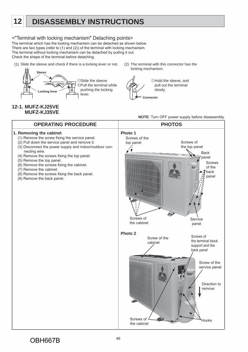
12-1. MUFZ-KJ25VE MUFZ-KJ35VE
NOTE: Turn OFF power supply before disassembly.
OPERATING PROCEDURE PHOTOS1. Removing the cabinet
(1) Remove the screw fixing the service panel.(2) Pull down the service panel and remove it. (3) Disconnect the power supply and indoor/outdoor con-
necting wire.(4) Remove the screws fixing the top panel.(5) Remove the top panel.(6) Remove the screws fixing the cabinet.(7) Remove the cabinet.(8) Remove the screws fixing the back panel.(9) Remove the back panel.
Photo 1
Photo 2
(1) Slide the sleeve and check if there is a locking lever or not. (2) The terminal with this connector has the locking mechanism.
Slide the sleeve.Pull the terminal while pushing the lockinglever.
Hold the sleeve, and pull out the terminal slowly.
Connector
Sleeve
Locking lever
Back panel
Service panel
Screws of the top panel
Screws of the cabinet
Screws of the top panel
Screw of the service panel
Direction to remove
Screws of the cabinet
Hooks
<"Terminal with locking mechanism" Detaching points>The terminal which has the locking mechanism can be detached as shown below.There are two types (refer to (1) and (2)) of the terminal with locking mechanism.The terminal without locking mechanism can be detached by pulling it out.Check the shape of the terminal before detaching.
DISASSEMBLY INSTRUCTIONS12
Screw of the cabinet
Screws of the back panel
Screws of the terminal block support and the back panel
OBH667B
47
OPERATING PROCEDURE PHOTOS2. Removing the inverter assembly, inverter P.C. board
(1) Remove the cabinet and panels. (Refer to 1.)(2) Disconnect the lead wire to the reactor and the following con-
nectors: <Inverter P.C. board>
CN721 (R.V. coil)CN931, CN932 (Fan motor)CN641 (Defrost thermistor and discharge temperature ther-
mistor)CN643 (Ambient temperature thermistor) CN644 (Outdoor heat exchanger temperature thermistor)CN724 (LEV)
(3) Remove the compressor connector (CN61).(4) Remove the screws fixing the heat sink support and the sep-
arator.(5) Remove the fixing screws of the terminal block support and
the back panel.(6) Remove the inverter assembly.(7) Remove the screw of the earth wire and screw of the termi-
nal block support.(8) Remove the heat sink support from the P.C. board support.(9) Remove the screw of the inverter P.C. board and remove the
inverter P.C. board from the P.C. board support.
Photo 3
Photo 4 (Inverter assembly)
Photo 5
3. Removing R.V. coil (1) Remove the cabinet and panels. (Refer to 1.)(2) Disconnect the following connectors: <Inverter P.C. board>
CN721 (R.V. coil)(3) Remove the R.V. coil.
4. Removing the discharge temperature thermistor, defrost thermistor, outdoor heat exchanger tempera-ture thermistor and ambient temperature thermistor(1) Remove the cabinet and panels. (Refer to 1.)(2) Disconnect the lead wire to the reactor and the following con-
nectors:<Inverter P.C. board>CN641 (Defrost thermistor and discharge temperature ther-
mistor)CN643 (Ambient temperature thermistor) CN644 (Outdoor heat exchanger temperature thermistor)
(3) Pull out the discharge temperature thermistor from its holder. (4) Pull out the defrost thermistor from its holder. (Photo 6)(5) Pull out the outdoor heat exchanger temperature thermistor
from its holder. (Photo 6)(6) Pull out the ambient temperature thermistor from its holder.
Discharge temperature thermistor
Screw of the R.V. coil
Heat sink
Screw of the earth wire
Screw of the Terminal block support
47
Screw of the inverter P.C. board
Heat sink support
P.C. board support Terminal
block support
Screws of the heat sink support and the separator
Screws of the terminal block support and the back panel
OBH667B
OPERATING PROCEDURE PHOTOS5. Removing outdoor fan motor
(1) Remove the cabinet and panels. (Refer to 1.)(2) Disconnect the following connectors: <Inverter P.C. board>
CN931, CN932 (Fan motor)(3) Remove the propeller nut.(4) Remove the propeller.(5) Remove the screws fixing the fan motor.(6) Remove the fan motor.
Photo 6
Photo 7
Photo 8
6. Removing the compressor and 4-way valve(1) Remove the cabinet and panels. (Refer to 1.)(2) Remove the inverter assembly. (Refer to 2.)(3) Recover gas from the refrigerant circuit.
NOTE: Recover gas from the pipes until the pressure gauge shows 0 kg/cm2 (0 MPa).
(4) Detach the brazed part of the suction and the discharge pipe connected with compressor.
(5) Remove the nuts of compressor legs.(6) Remove the compressor.(7) Detach the brazed part of pipes connected with 4-way valve.
48
Propeller nut
Screws of the outdoor fan motor
Propeller
Photo 9
Brazed parts of 4-way valve
Suction pipe brazed partDischarge pipe
brazed part
Defrost thermistor
Outdoor heat exchanger tempera-ture thermistor
Ambient temperature thermistor
OBH667B
49
12-2. MUFZ-KJ50VE NOTE: Turn OFF power supply before disassembly.
OPERATING PROCEDURE PHOTOS1. Removing the cabinet
(1) Remove the screws of the service panel.(2) Remove the screws of the top panel.(3) Remove the screw of the valve cover.(4) Remove the service panel.(5) Remove the top panel.(6) Remove the valve cover.(7) Disconnect the power supply and indoor/outdoor connect-
ing wire.(8) Remove the screws of the cabinet.(9) Remove the cabinet.(10) Remove the screws of the back panel.(11) Remove the back panel.
Photo 2
Photo 1
Screws of the cabinet
Screws of the top panel
Screws of the cabinet
Screws of the top panelScrew of the back panel
Screws of the cabinet
Screws of the service panel
Screw of the valve cover
Screws of the cabinet Screws of the
back panel
OBH667B
50
OPERATING PROCEDURE PHOTOS2. Removing the inverter assembly, inverter P.C. board
and relay P.C. board(1) Remove the cabinet and panels. (Refer to 1.)(2) Disconnect the lead wire to the reactor and the following con-
and outdoor heat exchanger temperature thermistor)CN672 (Ambient temperature thermistor) CN724 (LEV)
(3) Remove the compressor connector.(4) Remove the screws fixing the relay panel.(5) Remove the relay panel.(6) Remove the earth wires and the lead wires of the inverter P.C.
board.(7) Remove the screws of the P.B. support.(8) Remove the inverter P.C. board from the relay panel.(9) Disconnect the following connectors:
(10) Remove the screws fixing the P.B. holder.(11) Remove the relay P.C. board from the P.B. holder.
Photo 3
Photo 4
3. Removing R.V. coil (1) Remove the cabinet and panels. (Refer to 1.)(2) Disconnect the following connector: <Inverter P.C. board>
CN602 (R.V. coil)(3) Remove the R.V. coil.
Screws of the P.B. support
Screws of the relay panelInverter P.C.
boardEarth wires
Screw of the P.B. holder
Screws of the P.B. support
Brazed parts of 4-way valve
Screw of the R.V. coil
Screw of the relay panel
Relay P.C board
OBH667B
51
OPERATING PROCEDURE PHOTOS4. Removing the discharge temperature thermistor,
defrost thermistor, outdoor heat exchanger tempera-ture thermistor and ambient temperature thermistor(1) Remove the cabinet and panels. (Refer to 1.)(2) Disconnect the lead wire to the reactor and the following
connectors:<Inverter P.C. board>CN671 (Defrost thermistor, discharge temperature thermis-
tor and outdoor heart exchanger temperature ther-mistor)
CN672 (Ambient temperature thermistor) (3) Pull out the discharge temperature thermistor from its hold-
er. (Photo 7)(4) Pull out the defrost thermistor from its holder. (5) Pull out the outdoor heat exchanger temperature thermistor
from its holder. (6) Pull out the ambient temperature thermistor from its holder.
Photo 5
Photo 6
Photo 7
5. Removing outdoor fan motor(1) Remove the top panel, cabinet and service panel. (Refer to 1.)(2) Disconnect the following connectors:
<Inverter P.C. board>CN931 and CN932 (Fan motor)
(3) Remove the propeller.(4) Remove the screws fixing the fan motor.(5) Remove the fan motor.
6. Removing the compressor and 4-way valve(1) Remove the top panel, cabinet and service panel. (Refer to 1.)(2) Remove the back panel. (Refer to 1.)(3) Remove the inverter assembly. (Refer to 2.)(4) Recover gas from the refrigerant circuit.NOTE: Recover gas from the pipes until the pressure gauge
shows 0 kg/cm2 (0 MPa).(5) Detach the brazed part of the suction and the discharge
pipe connected with compressor.(6) Remove the compressor nuts.(7) Remove the compressor.(8) Detach the brazed parts of 4-way valve and pipe. (Photo 4)