Servicing &Technology JUNE 1984/$2.25 VHS basic recording and playing Waveforms Components Servicing Intellivision video games Voltage regulators Computerized scanner www.americanradiohistory.com
Transcript
Servicing &Technology JUNE 1984/$2.25
VHS basic recording and playing Waveforms
Components Servicing Intellivision video games Voltage regulators
Computerized scanner
www.americanradiohistory.com
New protectioñIéSpeôÏaUy in stormy weather for the electronics you use, sell or service!
A brief, high voltage surge - or spike - can occur in any AC line system and, at amplitudes lower than 600V, cause little or no damage.
But at greater amplitudes, a spike can do real damage. And the greater the high voltage surge - resulting from nearby lightning, for example - the greater the risk of harm, especially to solid-state devices.
That's why Zenith now announ- ces the availability of two Spike Suppressors - one with a grounding plug and the other without.
Both are designed to provide susceptible TV receivers, household appliances and other electronics with two-way protection from high - voltage surges.
First, a Zenith Spike Suppressor absorbs a wide range of voltage spikes so only a safe voltage level reaches the protected equipment.
Second, heavy or prolonged voltage surges cause a Zenith Spike Suppressor to cut off power com- pletely to protected equipment thereby signaling the need for a replacement Spike Suppressor.
That's double -duty protection against spikes for the electronics you use, sell or service. And ample reason for you to lay in a supply of Zenith Spike Suppressors soon.
Both should be available at your Zenith distributor's now. Call and pick up several before the next storm hits!
without Spike Suppressor
with Spike Suppressor
In this graph, the solid curve represents the excess voltage or "spike' imposed on an electric system and, represented by the dotted line, the protection provided household appliances as the Zenith Spike Suppressor absorbs the excess voltage and prevents it from surging thru the system.
The quality goes in before the name goes one
www.americanradiohistory.com
ELECTRONICS
THE ONLY ELECTRONICS PA COMPANY YOU'LL EVER NEED
That's not just an idle boast. Our new Catalog
has more than 4,500 qual ty parts and components -over 500 new items! And, it includes the largest selection of Japanese semiconductors in the country!
But MCM is more than a catalog. We're
dedicated people, working hard to serve you promptly and efficiently,
n'ith incredibly low prices! Calll today for your FREE ropy of our new 120 page Caitalc.g and jcin over twenty thousand satisfied customers who demand MCM quality. Call TOLL FREE FOR YOUR CATALOG 08. 1-800-543-4330 (in Ohio 1-800-782-4315)
RIGHT PAPTS.. RIGHT PRICE. SHIPPED HIGHT AWAY,
MCM Electronics ELECTRONICS 858 E. Congress Park Drive
Computer technology has revolutionized the world of electronics. The list of products that use microprocessors to enhance their performance is long and growing. This scanner radio is an example of a product designed to be used in conjunction with a computer to increase its capacity and make it easier to use. (Photo courtesy of Electra Company)
12 Voltage regulators for circuit projects By Michael A. Covington Three -terminal IC voltage regulators simplify power supply design. This article shows how to customize standard regulators to get nearly the precise voltage you need.
16 Test your electronic knowledge By Sam Wilson, CET This month's questions are about basic circuits and components.
18 Servicing Intellivision video games By Tom Strong, Director of Education, Electronic Servicing Institute, Cleveland, OH This how-to article tells you what can go wrong with Intellivision video games and how to fix them, as well as serving as an introduction to microcomputer servicing.
24 What do you know about components? By Sam Wilson, CET This article is the first in a series on components and their uses in fundamental circuits.
41 VHS basic recording and playing By Steve Bowden The circuit operations of VHS videocassette machines are described stage by stage with references to block diagrams.
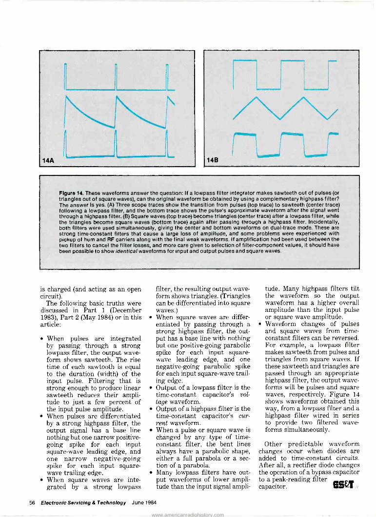
49 Interpreting waveforms, Part 3 By Carl Babcoke, CET This final segment of our waveforms series covers the effects of highpass filters on square waves and current voltage relationships in capacitive circuits.
60 At last, a source of computer servicing information Computerfacts booklets contain detailed information on servicing computers from several different manufacturers.
2 Electronic Servicing & Technology June 1984
www.americanradiohistory.com
..2x#-lüF - ,e ... _ .
fwursm
Page 18
Page 41
Page 49
Departments 4 Editorial
6 Technology
9 News
37 Symcure
38 Troubleshooting Tips
57 Photofact
58 Products
63 Readers' Exchange
Next month...
The TVRO Dish. This article describes how a satellite TV receiving system collects the microwave signal from the satellite and feeds it to the antenna. Satellite -dish siting con- siderations are also discussed.
June 1984 Electronic Servicing & Technology 3
www.americanradiohistory.com
Editorial
. e
The computer in your future "But what good is a home computer? Sure,
they make great video game playing machines, but a personal computer can't do anything for me I can't do myself. I mean, I know it can balance my checkbook, but I don't need a computer for that. And as for storing recipes and stuff like that, I can buy all the 3x5 card files I'll ever need..."
That's not an actual monologue, of course, but it does sum up some of the comments I've heard about computers. And right now many of them are pretty close to the truth. Computers do cost quite a bit of money, and most of them take quite a little bit of study to learn how to operate. But I think we're on the way to a period in the not very distant future when almost every home will have a computer, maybe more than one.
Consider the automobile. When it was in its infancy, as personal computers are now, drivers frequently were heaped with abuse including "get a horse." They were considered eccentric. Cars were noisy and uncomfortable, lacking things now considered standard, like heaters and defrosters. The tires were fragile, the roads lousy, and gas stations were few and far between. Still, automobile pioneers withstood those hardships and stood with the technology as it became refined into today's age of comfortable, economical, reliable automobile transportation with a car, and sometimes two or three, in almost every garage.
In many ways the inconvenience of using a personal computer of today can be compared to the inconvenience of those cars of an earlier age. Yes, they can do a lot of routine tasks but the user has to spend a lot of time learning to use the computer.
However, personal computers are constantly becoming less expensive and more useful. You can buy integrated units with a self-contained disk drive and monitor screen and with several software programs bundled in. And even now there are many things you can do with a personal computer that you can't do otherwise. You can make your own airline reservations or do your banking. If you have money invested in stocks you can check their current value any time. And if the library's closed and your youngster has a research project due tomorrow, just dial up The Source, or Compuserve, or any of a number of other on-line data bases and see what they have on file.
You can do all these things today. Right now. Imagine what the future might bring: Betty Crocker recipes on disk, direct access to your local library's data base so you never have to go in and check out a book, local store merchandise and price information. The possibilities are almost endless.
In the automotive world solid rubber tires that jarred and jounced over the road gave way to soft -riding pneumatics. Side curtains were replaced by crank -up glass windows. Gas stations sprang up on every corner. From an expensive luxury owned only by the rich, eccentric or enthusiast, the automobile has evolved into an absolute necessity.
The evolution of the personal computer has just gotten under way. It has the potential to be every bit as dramatic as that of the automobile. Just watch.
ELECTROAIO
Editorial, advertising and circulation cor- respondence should be addressed to: P.O. Box 12901, Overland Park, KS 68212.9981 (a suburb of Kansas City, MO); (913)888-4684.
EDITORIAL Bill Rhodes, Editorial Director Nils Conrad Persson, Editor Carl Babcoke, Consumer Servicing Consultant Rhonda Wickham, Managing Editor Jane Cigard, Associate Editor
ART Kevin Callahan, Art Director Joni Harding, Graphic Designer
CIRCULATION John C. Arnst, Director Evelyn Rogers, Manager Dee Manies, Reader Correspondent
ADMINISTRATION R. J. Hancock, President Cameron Bishop, Publisher Eric Jacobson, Associate Publisher
ADVERTISING Greg Garrison, National Sales Manager Liz Turner, Production Manager Stephanie Fagan, Marketing Coordinator
MP
Member, Audit Bureau of Circulation
Member, American Business Press
ELECTRONIC SERVICING & TECHNOLOGY (USPS 462-050) (with which is combined Electronic Technician/Dealer) is published monthly by Intertec Publishing Corp., 9221 Ouivira Road, P.O. Box 12901, Overland Park, KS 66212-9981. Second Class Postage paid at Shawnee Mis- sion, KS 66201. Send Form 3579 to P.O. Box 12952, Overland Park, KS 66212-9981.
ELECTRONIC SERVICING & TECHNOLOGY Is the "how-to" magazine of electronics. It is edited for electronic profes- sionals and enthusiasts who are interested in buying, building, installing and repairing home -entertainment elec- tronic equipment (audio, video, microcomputers, electronic games, etc.).
SUBSCRIPTION PRICES: one year $18, two years $30, three years $38 in the USA and its possessions. Foreign countries: one year $22, two years $34, three years $44. Single copy price $2.25; back copies $3.00. Adjustment necessitated by subscription termination to single copy rate. Allow 6 to 8 weeks delivery for change of address. Allow 6 to 8 weeks for new subscriptions.
PHOTOCOPY RIGHTS: Permission to photocopy for internal or personal use is granted by Intertec Publishing Corp. for librarles and others registered with Copyright Clearance Center (CCC), provided the base fee of $2 per copy of arti- cle is paid directly to CCC, 21 Congress St., Salem, MA
01970. Special requests should be addressed to Cameron Bishop, publisher. ISSN 0278-9922 $2.00 + 0.00
INTERTEC PUBLISHING CORP. 01984 All rights reserved.
www.americanradiohistory.com
Iteece
mar foe
Make it easy on yourself when you service Magnavox, Philco, and Sylvania sets. Reach for the parts that have earned their stripes.
N.A.P. factory authorized replace- ment parts make your job easier be- cause they're specifically designed for N.A.P. sets. The reliability of N.A.P. parts is assured because they are engineered to meet exacting factory specifications for specific applica- tions. And they're easy to get your nands on-readily available parts prevent unnecessary delays. N.A.P. parts are cost competitive and guar- antee you the quality and service you demand.
When you reach for N.A.P. replace- ment parts, you reach for the best.
Circle (5) on Reply Card June 1984 Electronic Servicing & Technology 5
www.americanradiohistory.com
Computer hookup
enhances operation of
scanner radio
Small computers have had a more profound effect on the world than most of us realize. Besides their obvious manifestations where they have been showing up in offices and homes to store infor- mation and perform routine re- petitive mathematical tasks, millions more have been imbedded in the circuitry of modern products where they perform their magic unnoticed: cars, microwave ovens, VCRs and digital audio disc players to name just a few.
In some of these applications, the computer enhances the prod- uct's value by making it easier to use, more efficient or faster. In other applications, the computer makes it possible to realize a useful, practical, marketable prod- uct that would not have been possi- ble without the nse of a microcom- puter.
One recently introduced prod- uct, the Bearcat CP 2100, is a scanner radio that was designed as a peripheral for personal com- puters. Now available in versions compatible with the IBM PC, Atari 800, Apple II and IIe., Osborne and Commodore 64, the scanner can monitor live police and fire calls, emergency and amateur radio transmissions, Coast Guard rescues and aircraft communica- tions.
Sca - ier radio informa- tion displa, on video screen e Iminates need to handle& bt of paper.
In addition, according to the manufacturer, this is the first scanner that can display detailed information about a service being monitored. Each of its 200 chan- nels can be programmed to display the source and location of a trans- mission, 10 -codes, phone numbers and more. Whenever a broadcast is monitored, the information pro- grammed into the channel will automatically appear on the screen. For scanner enthusiasts, the unit can eliminate pages of cumbersome frequency lists. In the newsroom, it can help news crews be dispatched to the scene of a story with less confusion.
Because of the computer connec- tion, the scanner offers several other advantages. Its 200 -channel capacity is three times that of the most sophisticated programmable scanners with channels grouped into banks of 20. It is also the first scanner to feature multiple priori- ty levels. Users can select up to three different priority frequen- cies so most important calls will be heard first. During a priority transmission, the video monitor will flash to alert the listener.
"Search/Store/Count" lets users search frequency ranges of their choice for active channels. The scanner will automatically find all active frequencies and store them in separate memory without the need for the operator to be pre- sent. The count register shows how many transmissions were noted on each active frequency. Also, every channel includes four auxiliary settings that can be pro- grammed to activate tape re- corders, alarms and other optional equipment whenever a call is received on a programmed channel.
Other features include patented "selective scan delay," "automatic lockout," "automatic and manual search," and patented "track tun- ing" The scanner's frequency cov- erage includes 10 -meter, 6 -meter, 2 -meter and 70 -centimeter amateur, VHF low and high, VHF aircraft, UHF and UHF -"T," and military land mobile bands.
The capability of computers to store, manipulate and display in- formation is being used in many ways to expand the capabilities of all kinds of products and processes from automobiles to zymurgy. You may try to ignore them, but they won't go away.
6 Electronic Servicing & Techno,ogy June 1984
www.americanradiohistory.com
We advanced the technology to make the soldering
simple. Sy changing the grounded
heat sensing tips, the Weller WTCPR automatica,' ly controls output and
temperature in bree stages (600°E 700°F and 800°F). Once selected, you can be assured of constant, accurate temperature control without dials to
turn or settings to watch. To make working with sensitive components
that safe and simple, We11eY has incor- orated state-of-the-art technology into attractive impact resistant case, that's
ideally suited to assembly work. Check with your Electronics Distributor.,
More Weller advances
If voltage transients are your problem, the WTCPZ has a -
special zerovoltage electronic switching circuit to prevent possible damage to sensitive components.
Coo erTods eree between work and workmanship.
R H CRESCENT R LUFKIN®NICHOLSON`IPLUMB®WELLER®WiSS®XCELfTE® The Cooper Group PO Box 728 Apex NC, 2; 502 USA Tel (319) 362-7510 Telex 579497
Circle (8) cn Raply Card
FVTCPE Solder- ing Station features
the WEC24 iron which has adjustable control
circuitry completely contained in
the handle.
www.americanradiohistory.com
Technology
THERE'S A LIMIT! How small can circuits get?
Someday, manufacturers will have made integrated circuits so small it will be impossible to make them any smaller. At least that sounds plausible. For the time be- ing, however, those of us on the outside looking in can only con- tinue to watch in fascination as manufacturers continue to push back the limits and realize ever more crowded slivers of silicon.
Researchers at Toshiba Corpora- tion have succeeded in developing the world's first 256K -bit CMOS static random access memory (RAM)-possibly called a next generation "ULSI" (ultra large scale integration) semiconductor, to be used for various types of computers and office automation equipment as a data storage device.
Using advanced 1 -micron preci- sion lithography and other VLSI (very large scale integration) technologies, the new device in- tegrates approximately 1.6 million elements (like transistors) on a 6.68mm by 8.86mm chip - the same level of integration as a 1 -megabit dynamic RAM. Channel lengths of the transistors are 0.9 micron.
Random access memory (RAM), which is available for free writing and reading of information, is divided into two structural types: static and dynamic. A static RAM needs four to six times the number
of transistors of a dynamic RAM to acquire the same memory capacity. Unlike the dynamic RAM, it does not need constant refreshing by electric pulses to keep the stored data from vanishing; therefore, it is easier to use. Static RAM also works much faster than dynamic RAM. A static RAM is often used for compact equipment with low power needs, while a dynamic RAM is used for relatively large equipment in- cluding mainframe computers where the cost of memory chips is the first priority. A 256K -bit RAM (both static and dynamic) can store a full page of a major newspaper.
Toshiba has long emphasized both dynamic and static memory LSIs and has developed a balanced operation in the LSI memory business. Samples of 256K -bit dynamic RAMs are already being shipped. The company has applied its long-standing CMOS (com- plementary metal oxide semicon- ductor) technology to static RAM, which produces chips that require much less electric power and generate less heat than standard models. Toshiba has developed a low -power consuming 64K -bit CMOS static RAM (capable of storing up to 8000 characters), which is equivalent to a 256K -bit dynamic RAM at its integration level.
The newly developed 256K -bit
Channel lengths of 0.9 micron (0.000035 inch) make possible the manufacture of 256K -bit static RAM.
CMOS static RAM features access time (time needed for writing and reading information) of as fast as 46ns or billionths of a second. Power consumption has been limited to only 2mA during opera- tion (10 to 20 times less than dynamic RAM) and 30µW during stand-by.
Because of these characteristics, it will probably be widely used as a memory in personal computers, of- fice automation equipment, measuring instruments and medical equipment, all of which re- quire ever -higher speed, larger memory capacity and lower power consumption.
The chip is classified as the next - generation "ultra" LSI - often called ULSI - filling the supposed qualification of more than one million integration on a chip. Generally, an LSI chip with more than 100,000 elements is called a VLSI. Both the current 256K -bit dynamic RAM and 64K -bit static RAM integrate 400,000 to 600,000 elements on a chip by precision lithography technology of two micron design standard. The 1.5µ
8 Electronic Servicing & Technology June 1984
www.americanradiohistory.com
Design rule (microns)
20
10
8
6
4
2
1
0.8
0.8
0.4
Transition of VLSI development \ 1KDRAM ` \ \
4kDRAM- e' 1KSRAM
`4KSRAM
\ o 84KSRAM\ 258KSRA
288KDR
84KDRA\ o1BKSRAM
1MDRAM
"' ó 4MDRAM 1MSROM - 481SRAM\ \ \
Number of translators (millions)
0.001
0.01
0.1
1
10
1970 72 '74 78 '78 1980 '82 '84 '86 '68 1990 '92
year
Static RAM featuring 256K bits may be the first of a class of memory devices called "ultra large scale integration." Projec- tions are that by the 1990s semiconductor manufacturers will be up to tens of millions of transistors on a single chip.
level has so far been thought to be the limit of current technological development.
To develop the new ULSI chip, Toshiba employed various
technologies including 1 -micron precision lithography, element separation, new circuit and aluminum multi -layer wiring technology. Toshiba expects the
combination of these technologies will make possible the develop- ment of 1 -megabit and 4 -megabit memory devices and other ULSIs in the near future. ase,
Satellite service technicians honored
Mission Specialists George D. Nelson and James D. van Hoften have been honored by the Interna- tional Society of Certified Elec- tronics Technicians with the titles of Honorary Certified Electronics Technicians. They are cited for outstanding technical achieve- ments in space during April 8-12, 1984, when the Solar Max satellite was serviced, repaired and re- turned to earth orbit.
The association honored the two astronauts for exemplifying the highest ideal of the electronic ser- vice industry by:
Preparing for the maintenance of high-technology electronic equipment through study, training and retraining.
Personal dedication to restoring faulty equipment to a standard of performance and reliability that
matches or exceeds the original. Performing technically precise
electronic service in hostile en- vironments consisting of weight- lessness, a vacuum and at orbital speeds.
Using state-of-the-art technolo- gy testing and service equipment to perform quality service.
Demonstrating that adequate preparation for service is essential in successful repairs.
Nelson and van Hoften used power tools designed for weight- less conditions to change and repair electronic instruments. Ex- tremely difficult and delicate work was required to repair the elec- tronics box for the Coronagraph- Polarimeter, which was not de- signed to be repaired in space.
ISCET establishes program to replace FCC licensing
People who hold current and valid FCC general radiotelephone operator licenses may renew those licenses with the International Society of Certified Electronics Technicians at any time prior to their expiration. The FCC recently repealed rules that allow only licensed people to repair or install
2 -way radio systems. Congress recently authorized the FCC to en- dorse industry certification pro- grams for technicians as a valid substitute for the previous licens- ing requirements.
Individuals holding current and valid general radiotelephone operator licenses may register those licenses with ISCET for a $10 registration fee. Each registration is valid for five years. Or, they may take the Certified Electronics Technician examina- tion with the Communications Op- tion for a $20 fee and, if successful, receive permanent certification. The Communications Option of this exam, which has been aproved by the FCC as a replacement for the general radiotelephone opera- tor license, includes a test of basic electronics circuitry and measure- ment, plus a specialized section covering 2 -way transceivers, basic eommunication theory, transmit- ters, deviation, sensitivity, quieting and troubleshooting.
For more information on license renewal or the CET program, con- tact ISCET, 2708 West Berry, Fort Worth, TX 76109; 817-921- 9101. G5A.
June 1984 Electronic Servicing & Technology 9
www.americanradiohistory.com
1946. Sams Introduces PHOTOFACT.
HOW Am S g CO.,INC., AR Radio Engineer's Service
I1iiIflTn1Arr* KIT 11FR SFT Nn 1
Your Inside Track To A Profitable Career In Microcomputer Servicing.
It started in the early days of television. Sams began reconstructing and documenting how technology works and published its first PHOTOFACT TV service manual.
But Sams didn't stop there. Sams continued to apply its technical expertise in new areas. And in 1967, released the first computer book.
Now Sams has combined its knowledge of computers and technical servicing to bring you COMPUTERFACTS-the first and only technical manual series for servicing today's microcomputers and peripherals.
The Future Is Bright. The market for servicing personal computers is growing at an average
rate of 36% per year. A national research survey shows computer technicians earn almost 20% more than TV servicemen.
Buy Sams COMPUTERFACTS and you've got the inside track to a profitable career in this growing field. Because only COMPUTERFACTS have all the technical information you need to service computers right now.
1I 2 I 3 4 I 5
A
C
Offer good in USA only. Prices and availability subject to change without notice. In Canada, contact Lenbrook Electronics, Markham, Ontario L3R 1H2.
Apple is a registered trademark of Apple Computer, Inc. Commodore is a registered trademark of Commodore Business Machines Inc. Atari a registered trademark of Atari, Inc. Osborne is a registered trademark of Osborne Computer Corporation. Diablo is a registered trademark of XEROX CORPORATION. TI 99/4A is a registered trademark of Texas Instruments, Inc. PHOTOFACT is a registered trademark of Howard W
Sams & Co., Inc. COMPUTERFACTS is a trademark of Howard W. Sams & Co., Inc.
10 Electronic Servicing & Technology June 1984
www.americanradiohistory.com
Sams 1984.
ntroduces COMPUTERFACTS:
-
COIJ.p,TC6REpL..CS
415V 5µs
PART OF
UD2 74LS20PC
PART OF
UA2 ND74LSOOP
2.36V
ßi1 '110 / 8I 5
4
R1 4256113 7 4 3.43V
COMPUTERFACTS Will Get You There. With COMPUTERFACTS in hand, you have a complete guide to every major computer and component made including data storage devices, modems, monitors, and printers by Apple®, Osborne®, Commodore°, Atari®, Diablo° TI 99/4A®, and others.
And like PHOTOFACT, COMPUTERFACTS cover every circuit, chip and control thoroughly and accurately with pages of:
Parts descriptions Terminal guides Troubleshooting hints
So you can spot and service problem areas in minutes.
Save On New COMPUTERFACTS Every Month. Sams will keep you updated on the latest in computer servicing with new COMPUTERFACTS every month. By joining Sams "COMPUTERFACTS-OF- THE-MONTH" Standing Order program, you'll immediately receive every COMPUTERFACTS product as it's finished, and at substantial savings. COMPUTERFACTS-OF-THE-MONTH normally include one computer, a printer or terminal, and a modem or disk drive. So get Sams COMPUTERFACTS and get on the fast track to a profitable career. To order, contact your local Sams representative. Or call OPERATOR 133 at 317-298-5566 or 800 -428 -SAMS.
5ßM5M What Technology Is All About.
HOWARD W. SAMS & INC. 4300 West 62nd Street, P.O.
CO.Box 674
Indianapolis, IN 46268 Circle (8) on Reply Card
June 1984 Electronic Servicing & Technology 11
www.americanradiohistory.com
Voltage regulators for circuit projects
How to customize the output of a 3 -terminal IC voltage regulator
Three -terminal IC voltage regu- lators have practically all the vir- tues a circuit builder could wish for. They are inexpensive and easy to use, and they solve a whole set of thorny design problems. A 75 -cent IC with three simple con- nections can replace what would have been a complex, difficult -to- design circuit involving large capacitors, transistors, a zener diode, and perhaps an op amp or two.
In fact, thanks to IC regulators, cheap tape recorders and desk calculators often have better power supplies than were found in even the best laboratory equip- ment a few years ago, and hum in audio equipment is nowadays almost nonexistent.
What they do A 3 -terminal regulator accepts a
widely varying input voltage at its input pin and delivers a constant output voltage at its output pin. The third pin is connected to ground. No extra circuitry is re- quired. For example, the popular type 7805 5V regulator accepts an input anywhere between 7V and 35V (which can be continuously varying) and delivers a rock -steady 5V of output.
IC voltage regulators are good at getting rid of residual ripple on the incoming supply line. For in- stance, the 7805 attenuates 120Hz ripple by about 80dB. That is, it reduces the ripple to about 1/10,000 of its original amplitude- so small that you can ignore it.
Voltage regulators also elimi- nate variations in output voltage caused by variations in load cur- rent. Most power supplies deliver a voltage that decreases as the load gets bigger. The decrease is due to the internal resistance of the power supply, across which there is a voltage drop proportional to
By Michael A. Covington the load current. The voltage regulator makes the power supply look as if its internal resistance were on the order of 0.010; the voltage drop becomes negligible.
And that's not all. Voltage regu- lator chips include a feature- built- in current limiting-that was pre- viously rare in power supplies of any kind. You can't damage a volt- age regulator chip by connecting too heavy a load or even shorting the output. As soon as the chip be -
Figure 1. Equivalent circuit of type 7805 voltage regulator.
gins to overheat, it shuts down, cutting off the output current. Be- cause the current limit is set by a temperature sensor built into the chip, it doesn't matter what the ambient temperature is or whether a heat sink is present; the regulator always shuts down as soon as it goes out of its safe operating area. It can stay in shut- down mode indefinitely without damage.
How they do it Figure 1 shows a simplified
equivalent circuit of a type 7805 voltage regulator. You can think of it as a variable resistance be- tween input and output that auto- matically adjusts itself to drop ex- actly the right amount of voltage. For instance, if you have 30V com- ing in and 5V going out, you need a 35V drop. The resistance needed, in turn, depends on the load cur- rent. The voltage regulator chip senses the voltage between the output and ground pins and ad- justs the resistance to bring it to the correct value. The only restric- tions are that the voltage drop
Type: Case style:
LM317T TO -220
LM317LZ Plastic
LM7805CT TO -220
LM78L05 Plastic
Typical wholesale price: $1.19 $0.75 $0.79 $0.75 Regulated voltage (VR): 1.2 1.2 5.0 5.0 Minimum VDROP: 2.5 2.5 2.0 2.0 Maximum current (at
VDROP = 5V)
without heat sink: 400mA 100mA 400mA 100mA with heat sink: 1.5A 1A
Maximum dissipation (W) without heat sink: 2 0.6 2 0.5 with heat sink: 15 20
Ground pin current (mA): 0.1 0.1 5 3
Table 1. Characteristics of some popular 3 -terminal regulators.
12 Electronic Servicing & Technology June 1984
www.americanradiohistory.com
I mV DIV. VERTICAI.
SENSIVITY
V -MODE DISPLAYS
NRELATED SIGNALS
1 mV VERTICAL
SENSITIVITY DELAYLI) SWEEP WITH T'2At is SFPAR- 1'It+N
HI:H ACCELERATION VOLTAGE
DUAL TRACE ON 1580
TFIPLE TRACE ON 1560
DUAI. TRACE ON 1540 XID SWEEP MAGNIFICATION
1 tl IAL
TIME BASE
Three ninr BKK -PRECISION scopes loaded with features
at competition -busting prices.
s.ostom, \
60MHz 1560 $1,150
I OnMHz 1580 51.595
I r Ht MORE INFORMATION, see the L.. t B&KPRECISION catalog. For your free copy, contact your local distributor or B&K-PRECISION.
i
OKPRECISAOIIf
40MHz 1540 $950
DYNASCAN CORPORATION
6460 West Cortland Street Chicago. Illinois 60635.3121889-9087
Inl,'rn.+Urmal Salas, 6400 W Cortland Chicago. Illinois 60635 Car Caadran Sale las Electronics. Ontario
South nul C;+mlral An.. n, .in Sali+, -mtnn f- x ers. Plainview. NY 11803
Circle On on Repiy Card
www.americanradiohistory.com
V,ex + 0.6 with silicon diode V,¢R + 1.6 with LED
1 Filter capacitor if nearby, or 0.1µF
JIM R
V,PR x R, +132 R,
R2
R2 <500Q with 7805, 20K with 317
Figure 2. Circuits using 3 -terminal regulator chips.
must be at least 2V, and that maxi- mum ratings on input voltage (typically 35V), current and power dissipation must be observed.
Naturally, this voltage drop wastes power. If you have a 5V load drawing 100mA, the load itself is consuming 0.5W. How- ever, if you power this from a 10V source through a 7805, the input current is still 100mA (plus a few mA drawn by the regulator itself), so that the total power consumed is a bit over 1W. The extra half - watt is converted to heat inside the regulator. In situations where this kind of power waste is unaccep- table, a different kind of power supply known as switching regula- tor or dc -to -dc converter should be used. Unfortunately, switching regulators are difficult to design.
Obtaining nonstandard voltages Three -terminal regulators are
manufactured in a wide variety of voltages: 1.2, 5, 6, 8, 9, 12, 15 and
18V, to name a few. Not all of these are regularly available at low prices. Usually, the 317 (1.2V), 7805 (5V), 7812 (12V), and 7815 (15V) are easier to obtain, and cheaper, than the others. The 7805, which is used extensively in computers, is particularly abun- dant.
Moreover, sometimes you need a voltage that is not in the standard set, or you need to vary or trim the output voltage. In these cases a customized voltage regulator cir- cuit is the only answer.
The key to customization is to realize that the ground pin of the regulator need not be connected to circuit ground. It can be con- nected to anything that is at a con- stant voltage above or below ground. The 7805 maintains the output pin 5V above the ground pin voltage, whatever that may be.
The simplest way to raise the ground pin above ground in a con- trolled way is to place a voltage
drop in the path of the 3mA to 5mA current that flows out of it. This can be done with a ger- manium diode (0.3V), a silicon diode (0.6V), an LED (1.6V red, 2.1V green), or a zener diode (Figure 2). For example, a 7805 with a red LED in series with its ground pin gives an output of 6.6V-exactly what you need to power a 6V tape recorder or calculator from a 12V automotive supply. In fact, if the LED is a low - current type, it will even glow brightly enough to serve as a power -on indicator (no series resistor is needed).
You cannot simply place a resistor in series with the ground pin if you want good regulation, because the ground -pin current is not quite constant. But you can use a voltage divider to place the ground pin midway between the output of the regulator and true ground, as shown in the last of the four diagrams in Figure 2. The resistor from the ground pin to cir- cuit ground should be below a limit that depends on the type of chip used (50012 for the 7805; it could, of course, be zero). The value of the other resistor depends on the out- put voltage desired. The formulas are:
V.,,, = V x ((R, + R2)/R, )
R, = R2/(V.ur/V..B-1)
V,,,, must, of course, be greater than V8. The voltage divider does consume some current, and it reduces the quality of the regula- tion slightly by allowing variations in ground -pin current to affect the output.
With this in mind, compare the 7805, advertised as a fixed 5V regulator, with the 317T, billed as an adjustable voltage regulator (Table 1). The only important dif- ferences are that, for the 317, Vg is lower, so that the output voltage can be as low as 1.2V, and the ground -pin current is much smaller, so that the voltage divider resistors can be larger without in- troducing a substantial error. Both regulators are equally "adjustable in that they can be used in the cir- cuits of Figure 2. Where the regulated voltage is above 5V and relatively small divider resistors are feasible, it is often cheaper to use the 7805. ISM,
14 Electronic Servicing & Technology June 1984
www.americanradiohistory.com
WHAT DOES CHARLIE BROWN SEE IN CONIFER'S SATELLITE SYSTEM? After 95 Installations In Just 12 Months, Brown is Sold on Conifer!
Out of his quaint shop in Knoxville, Illinois, Charlie Brown has become one of the most dynamic Satellite TV dealers and installers in the country. With over 15 years experience in electronics sales and service, the last three years in
TVRO, Brown knows how important quality products and service can be to the success of his business.
WHY DID BROWN CHOOSE CONIFER? "When I first saw the Conifer DE -2001 system it was far ahead of anything else I had seen. The price point was better than anything else on the market."
WHY DID YOU CONSIDER CONIFER THE BEST VALUE? "Conifer had the features that I wanted to sell. Everything was contained in one unit...the dish drive, the Polarotor, one cable...everything!"
WHY DO YOU LIKE THE MESH? "It blends in well with surroundings and looks better than a
solid dish. You can install a Conifer black dish (AN -1200C) in a wooded area and it blends right in."
WHAT ABOUT INSTALLATION? "After the base is set we can assemble the dish and have a
good picture in less than two hours. It really helps that the aluminum mesh is attached to the petals at the factory."
HAS CONIFER LIVED UP TO YOUR EXPECTATIONS? "The very first Conifer system I sold and installed I've never made a service call on. It works as good as the day it was installed. I think Conifer still has the best system and mesh dish on the market. No question about it!"
WHAT HAS CONIFER DONE TO HELP DEALERS BE MORE SUCCESSFUL? "I highly recommend that a new or experienced dealer call
or write Conifer to get a FREE copy of their new booklet 77
Ways To Succeed In The Home Satellite TV Business. It's Great!"
CONIFER CORPORATION 1400 N. Roosevelt Burlington, IA 52601 319-752-3607 (Iowa Calls) 800-358-3058
Circle (20) on Reply Card
June 1984 Electronic Servicing & Technology 15
www.americanradiohistory.com
Test your electronic
knowledge B Sam W so CE
These questions are similar to questions used in the associate - level CET test. All questions in the actual CET test are multiple choice, and a grade of 75 percent or better is required for passing. This month's questions are about basic circuits and components. (Answers on page 59.)
1. By redrawing the circuit in Figure 1 it is easy to see that A. the current through R3
equals the current through R4.
B. the current through R3 is greater than the current through L.
C. the current through R3 is less than the current through R4.
D. there is no current through R3.
2. Any 2 -terminal network com- posed of linear, bilateral cir- cuit elements and one or more sources of do voltage can be replaced by the circuit shown in Figure 2. This is A. not true. B. sometimes true. C. Norton's theorem. D. Thevenin's theorem. E. Kirchhoff's law.
3. Which of the following com- ponents produces a voltage that is directly related to the strength of a magnetic field? A. CCD. B. Thyristor. C. Hall device. D. Bead ledge.
R,
4004
R,
4004
v 10 volts
Figure 1
R.
3004
- V
R
"V1/V----0
Figure 2
4. A relaxation oscillator A. has a non -sinusoidal out-
put waveform. B. has a frequency that is di-
rectly related to time con- stant.
C. can be synchronized. D. can be made with NPN or
PNP transistors. E. All of the above.
5. Iron is attracted by a magnet- ic field, but some materials are repelled by a magnetic field. A. True. B. False.
E. In the circuit of Figure 3, the resistance between points A and B is A. 25052 B. 15052 C. 5052 D. 37.552 E. 2552
16 Electronic Servicing & Technology June 1984
www.americanradiohistory.com
One source for thousands of VCR parts.
RCA VCR parts are available from more than 600 authorized RCA parts distributors. See your local RCA distributor for RCA's new VCR parts kits - they're easy to use and reuse. Each package has a handy slide top - and features detailed cross-references to other manufacturers' model numbers and stock numbers.
One more thing. Kit prices are lower than the total cost of the individual parts. So see your RCA distributor today. Also ask for a
copy of the VCR Parts Cross Reference of more than 8000 VCR parts (Form 1F6627) and VCR Tool Catalog (Form 1F6857). Or write: RCA Distributor and Special Products Division, 2000 Clements Bridge Road, Deptford, NJ 08096.
Service more than 95 RCA and other brand models with these VCR Parts Kits:
199094 and 199095 Belt Kits, 199096 Lamp Kit, 199097 Fuse Kit, 199300 IC Kit Rcß VCR Parts
7. Refer to Figure 4. Which of the following statements is correct? A.
B.
Obviously, the circuit has no practical applications. Diodes allow current to flow in one direction, but that purpose is defeated when 2 -way resistors are connected across them. There is a perfectly good reason to connect resis- tors across diodes as shown in Figure 4. The cir- cuit has practical applica- tions.
8. Which of the following state- ments is correct regarding a bifilar winding? A. It is used to increase the
inductance of a coil. B. It is a non -inductive wind-
ing.
9. In Figure 5 the voltage, induc- tance values and switches are
-fir- -MA,-
Figure 4
C
identical. In the circuit marked B, R = XL. The switches in both of the circuits have been closed for a long time. Now, both switches are to be opened at exactly the same instant. Which of the following state- ments is correct? A. The induced voltage is the
same in each circuit. B. The induced voltage is
higher in circuit B. C. The induced voltage is low-
er in circuit B.
10. Which of the following state- ments is true regarding a swinging choke? A. Its inductance does not
change if the amount of current through it changes.
B. Its inductance decreases if the amount of current through it increases.
C. Its inductance increases if the amount of current through it increases.
June 1984 Electronic Servicing & Technology 17
www.americanradiohistory.com
Servicin Intellivision
video games
By Tom Strong, Director of Education, Electronic Servicing Institute, Cleveland, OH
TURN : 3
J
A video game is really nothing more or less than a single -purpose computer with limited input and output options. For that reason, fixing your video game is less in- volved than fixing a general- purpose small computer, but at the same time it will give you some of the skills and confidence to jump right in when you face a defective computer. And the good news is that you don't necessarily have to go out and plunk down a small for- tune on specialized, sophisticated test equipment. Many problems will yield to skillful probing with two familiar pieces of test gear: a good VOM and a high -frequency oscilloscope, such as the Tektronix model 2213, 60MHz scope for measuring digital waveforms.
Figure 1 illustrates the com- puter operation of the Intellivision video game. Typical microcom- puter stages include the micropro- cessor (MPU) Ul, clock generator, read only memory (ROM) and ran- dom access memory (RAM) chips, TV interface chip (STIC), and U6, which is the interface between the hand controllers and the computer system.
Game objective Two hand controllers are pro-
vided for the user's communica- tions with the microprocessor, which in turn reacts by changing the video pattern in accordance with the user's input to the game controller and the game cartridge programming. The Intellivision circuits are processed in two ways: one computes the game action against the stored program rules of the game cartridge, and the sec- ond interprets a condensed memory area and uses this to generate the TV video display. The second processor fetches moving and background pictures from the graphic memory and presents the data as a video output. The draw- ing of pictures on the CRT is in ac- cordance with the instructions of the game cartridge program. The microprocessor directs this entire system by sending timed signals to the controller interface and memory.
Microprocessor The microprocessor is the heart
of the system. This 40 -pin chip is
www.americanradiohistory.com
nothing more than a device that does exactly what it's told, step by step. The instructions given to the MPU are stored in the form of binary codes in memory, which in- cludes the game cartridge. Each instruction directs the processor to perform a single logical operation. Say you're using the Poker game cartridge and you've just won $100. The game's computer adds this amount to your previous total. As another example, if you're play- ing a game of Blackjack, and your card score went over 21, your hand is completed. The MPU will start performing instructions in another area of memory for the second player.
This last example is a key point: the machine has decision -making capability. Normal program execu- tion proceeds in a single sequential fashion. The first instruction is at location 0, then 1, then 2 and so forth. In Blackjack, the MPU will allow a player to receive cards un- til the count exceeds 21. At this point, the processor encounters an instruction that says "Branch to location XXXX when total is more than 21." The microprocessor will obey. The first player will no longer receive any cards, and now the second player plays.
The signals in and out of an MPU can be divided into Address, Data and Control groups.
BUS CONTROL LINES
U1
MPU
16
16
US
PROGRAM
ROM
U9
PROGRAM ROM
1.112
SCRATCH PAD RAM
U7
DUAL PORT
RAM
e
U6
SOUND -I/O PORT
O O 2 KEY PAD
CONTROLLERS WIN POSS.DIRECTION CONTROL DISCS
1 1V
STIC
5
U10
COLOR CLOCK
GENERATOR
97
OVERLAPPING CLKS
MODULATOR Valhi
AyD.0.1N
U5
GRAPHICS ROM
el IQ
S, GRAPHICS
RAM
RF TO TV
f
ue
GRAPHICS RAM
e eLe
Figure 1. Block diagram shows how functional blocks that comprise the Intellivision video game are interconnected.
Memory Location Binary Bits in ROM Image
1000 0 0 0 1 1 0 0 0
1001 0 0 1 0 0 1 0 0
1002 0 1 0 0 0 0 1 0
1003 0 1 1 1 1 1 1 0
1004 0 1 0 0 0 0 1 0
1005 0 1 0 0 0 0 1 0
1006 0 1 0 0 0 01 0
1007 0 0 0 0 0 0 0 0
Figure 2. Characters shown on the game screen are defined by digital information stored in memory. Here, eight bytes define the letter A.
Address-these lines present an address in binary to access cer- tain memory locations according to the game program.
Data-after the information (data) is located in memory, it is transferred to the MPU where it is processed. The result could be the start of a new game, movement of an object on the screen or a change in the game score.
The microprocessor in the Intel- livision game (CP1610) uses the same lines for both data and ad- dress. These lines are labeled DO thru D15. The data -address lines are multiplexed or selected as needed.
Control-the control signals consist primarily of the two out -of - phase clock signals (e1 and 42), and the bus control signals BC1, BC2 and BDIR. One clock signal latches the proper address into memory and the other clock pulse retrieves the located data from memory. The clock controls the timing of all movements in orderly fashion. Each movement is timed in sequence. This prevents over- lapping of signals and allocates a definite period of time to perform the required task. Without these square -wave clock signals nothing happens; the game or computer is shut down.
The bus control signals are also vital. Their signal codes select either the address or data lines to be functioning on the MPU. The bus controls designate when data is written into memory. Also, the program may introduce a special effect into the game, such as a sur- prise spaceship flying above. The interrupt in the normal program has a bus control code.
Memory chips The memory circuits contain
both ROM and RAM. A ROM memory may be considered to be like a look -up table where informa- tion is permanently recorded and may be read out. All the possible functions of the video game are contained in ROM. In a way, this may be likened to a dictionary that has the definitions of every word. The instructions in the game pro- gram select only the desired infor- mation. The complete ROM memory consists of the game car- tridge and ICs U3, U9 and U5.
June 1984 Electronic Servicing & Technology 19
www.americanradiohistory.com
Servicing Intellivision
video games
These firmware chips contain the program, game rules, special ef- fects and graphics. For example, suppose the game cartridge pro- gram instruction calls for the video screen to display a tank. The loca- tion addressed in memory contains a series of bits that create the im- age of a tank when displayed on the screen. The program lists the proper addresses where this data is located. Some games include the sound of the ring of a bell. In that case, the game cartridge will con- tain a subroutine that reads the data from ROM to produce a bell - ringing sound.
Let's take a simple example to il- lustrate the workings of a ROM. The program calls for the letter A to be displayed on the screen. Each character is formed in an 8 x 8 grid of dots, where each dot may be "on" or "off." The character images are stored in the ROM chip. A low (0) bit means that a dot is off, and a high (1) bit means the dot is on. Suppose the character memory in ROM begins at location 1000 to display the first letter of the alphabet. The next eight bytes (remember, a byte is eight bits), from location 1000 to 1007, con- tain the data for forming the letter A (see Figure 3).
The RAM, on the other hand, is the hardware memory where data will be stored temporarily and then changed. Integrated circuit U12, for example, is used as a "scratch pad" memory. One func- tion it performs is to keep score. These functions are temporary and change as the game pro- gresses.
Circuit operation With power applied, U10
generates the 3.58MHz clock signal to U4, the Standard Televi- sion Interface Chip (STIC). Refer to the IC pinout diagram, Figure 3. The two overlapping clock signals are formed by the STIC to synchronize the MPU and the graphics ROM (U5) and RAM (U7 and U8). Instructions from the Program ROMs (U3 and U9) begin operating on commands from the MPU. The program ROMs provide instructions for the MPU to deter- mine whether a game cartridge is inserted.
If a game cartridge is in place, the MPU then gathers data from
O 1
42 B01' BC2 BCI
SR2 SRI 5R3
NSYNC
CLOCK
21
1
12
i BC r BC2
Ì801R DBB
6
3
DBO
ADORO
RE N 2 A10 p
3 A9 a
G
AR
5
K DB15 G
13
11
t
oe,a
120
}
1!
P
2 O
3
2
.Z
11
I I I
Mattel Electronics presents
BLACKJRCK t PURER
Copr 2 1979 Mattel
Figure 4. The title page appears on the screen when power is turned on with a game cartridge inserted.
Figure 5. Play is started by pressing any hand controller button.
www.americanradiohistory.com
BOOR
BC2
SCI
RESET
CU( CC
70 19 ie
16 . ,5 io
AO
Al
A3 A{
AS ea o7
6 D 06 AT D5
R/g01
1;7'ñ 03
Oo
0,
52 VSS
VGC_
á
-1Q -2Z. _î00W5
901214
BAR. MSYNC 018' SRI
SST 01315
DOI3 ,z
t= 3
I1312 I15117
2,e..-4.21§-__
in D
11
IU
9
A3 19
Ae 9 13 A2 39
L0 Rw e 75 N A7
AENA ,le E AO -
292
2G
A7 9
A{ 0
6
3
23
2e
D]6
rn s
,n <6 - _
27 A3 K
2 30 .'-,1
3 +í
29 3t
]7
A2
Ai
AQ, v55
,
000.3A_ vcc
32 ,< c5 ,
D99
Z - 121
111 I22
Figure 3. Pinout diagrams of some of the more important ICs in the Intellivision video game.
the cartridge ROM for U2, the dual port RAM which, in turn, passes the graphics information to the 14 -bit graphics bus (SDO thru SD13, U2). This RAM accepts data from Ul via a 16 -bit bidirectional bus that is time multiplexed with address and data.
Bus Control 1 and 2 and Bus Direction (pins 14, 15 and 16) com- prise the strobe signals from the MPU. The STIC decodes this graphic data and supplies video in- formation such as sync, color burst, luminance levels and chroma to integrated circuit U10, which is a multipurpose device pro- viding clock and color signals. The STIC may also call up a number of graphic shapes and characters
Figure 6. The ribbon connector bridges the power supply to the logic board. U1, U2, U4, and U6 are ICs that are common causes of problems. See text.
IC VOLTAGE CHART Pin U1 U2 U3 U4 U5 96 U7 U8 U9 U10 U11 U12 U13 914 915 916 U17
from the ROM/RAM graphics. The color IC subsequently converts all coded sync and video information from digital to analog, along with the external resistor network con- nected to the RF modulator to form the "title page" shown in Figure 4.
The MPU then waits for signals from the two keypad controllers to start the game (Figure 5). This is accomplished by pressing any one of the keypad buttons. The hand controllers load their commands into 8 -bit port registers in the sound generator and I/O chip (U6), one port for each controller. The microprocessor scans these registers for game start, speed and object direction. Sound is also generated from U6. Pins 3, 4, and 38 are tied together to provide the analog (sound) output to Q3, which amplifies the audio signal to the modulator. At the modulator, audio and video are combined on carriers for either channel 3 or 4, as selected.
Power supply A ribbon connector bridges the
power supply to the main circuit board as shown in Figure 6. This supply provides four separate voltages that can be measured at the ribbon connector:
5V regulated for most of the chips -3V for U1 and U2 12V regulated for Ul, the modulator and Q3 16V unregulated for Q1 and Q2
The 5V regulator uses a TO -220 casing IC (replacement No. 7805). Its input voltage is about 9V; the output voltage is 5V. The 12V regulator also uses a TO -220 cas- ing IC (replacement No. 7812). Its input voltage is 16V, providing a regulated 12V output.
Troubleshooting When the game console is
turned on with a game cartridge inserted, the title page of the game appears on the TV screen. To start the game, press any button on either hand controller. This will cause the game program to be switched on from the title page. As mentioned in the circuit descrip- tion, IC U6 serves as the interface between the hand controllers and the MPU. Pins 6 thru 21 on U6 are
June 1984 Electronic Servicing & Technology 21
www.americanradiohistory.com
Servicing Intel livision
video games
connected to the two hand con- trollers. Notice on the IC voltage chart in Figure 7 that these 16 pins read HIGH (4.7V). When one of the pins is brought low (0V) by pressing any button, the game is enabled.
The most common difficulty in the Intellivision game is the inabili- ty to switch from the title page to the game program. If any of pins 6 through 21 read low when the unit is turned on, the title page cannot be switched to the game program. This could be caused by either a shorted hand controller or defec- tive U6. A less likely cause would be any one of capacitors C34 to C39 shorted to ground.
The two hand controllers can cause problems because of con- tinuous hard use. On each hand controller (Figure 8), there are 17 buttons (switches) located on a plastic matrix. When defective, this switch assembly can be re- placed as a single unit. Bad con- nections and broken wires are other problems associated with the controllers. A check of continuity of the wires can locate this defect.
It is possible that some buttons on the controller may function and others may not. Figure 9 shows what hand controller buttons are connected to U6 and the individual IC pins. Pins 6 thru 21 are normal- ly high; the chart shows which pin goes low corresponding to the con- troller buttons when pressed.
Another common problem is a blank white screen (no video and no snow). This is the most difficult symptom to diagnose because almost any of the unit chips can cause a blank screen. (The excep- tion is U6 - experience has shown when this chip is defective only the title page will appear.)
Troubleshooting steps These steps assume that power
supply voltages are normal. Check both clock pulses at MPU
(U1) on pins 37 and 38. They should read 13V peak to peak. If readings are normal, this clears U4 and U10 because U10 (color IC) generates the master clock pulse, and U4 (STIC) forms the two out -of -phase clock pulses. Notice: The two clock pulse outputs of U4 (pins 10 and 11) are 5V, and at the MPU they read 13V. Buffer IC Ull's open collector design develops this
larger voltage going to the micro- processor. Also, if the clock signals and DC voltages are normal at the MPU, the probability is that Ul is OK.
Check pin 2 at the MPU (M sync). It should read 5Vdc, and when RESET is pressed a momen- tary low should be recorded. The reset switch when activated sets the program counter to a known location in ROM, which causes the title page to appear.
Check the 16 data lines and bus control lines (pins 3, 4, 5) at the MPU for waveforms on the 5V range of the scope. It is impossible with an oscilloscope to ascertain if the shapes of the data and bus con- trol signals are correct. The wave- forms will look strange. For- tunately, you're only concerned that there are signals present at these pins. If so, you can then feel confident the system is working át these stages. If the signals are missing, a shorted chip directly connected to these lines is loading down the MPU. Suspect U2 (RAM), U12 (RAM), U3 (ROM), or U9 (ROM). Remove one chip at a time and recheck if the data and bus control signals appear at the MPU.
If the data and bus control lines are normal at the MPU, trace the BC1, BC2, and BDIR signals to U16 (nand gate), U13 (nor gate) and U17 (exclusive or gate). These bus control signals continue to the game cartridge socket on pins 32, 34 and 36. Here they are distribu- ted to U3 and U9 (program
Figure 8. The hand controller is the player's input device to the game.
www.americanradiohistory.com
ROMs), U4 (STIC), U6 (con- troller - sound chip).
Figures freeze or wrong sequence of events
in some cases, while playing the game the figures on the screen won't move, or there is an im- proper sequence of events, or the letters and images on the screen are inaccurate. These symptoms all point to a "senile" memory. Try replacing U2, the dual port RAM.
Snow on screen This symptom suggests little or
no modulated video signal is being received at the TV's antenna in- put. This series of troubleshooting steps should isolate the problem:
Substitute another antenna game switch Substitute antenna coax cable Check if modulator output jack is loose Check game's channel selector switch.
A, right (Referring to UG correspond to buttons correspond to buttons correspond to buttons correspond to buttons correspond to buttons correspond to buttons
A6, Pin 15 correspond to buttons
A7, Pin 14 correspond to buttons
(On the circuit board, controller A front of two chips.)
Controller B, left BO, Pin 13 correspond to buttons 131, Pin 12 correspond to buttons B2, Pin 11 correspond to buttons B3, Pin 10 correspond to buttons B4, Pin 9 correspond to buttons B5, Pin 8 correspond to buttons
B6, Pin 7 correspond to buttons
B7, Pin 6 correspond to buttons
pinout diagram) 1,2,3
4,5,6
7,8,9
clear, 0, enter disk 3,6,9, enter, left side top and bot- tom, right side top 2,5,8,0, left side bottom, right side bottom 1,4,7, clear, left side top, right side top and bot- tom
socket is located in
1,2,3
4,5,6
7,8,9
clear, 0, enter disk 3,6,9, enter, left side top and bot- tom, right side top 2,5,8,0, left side bottom, right side bottom 1,4,7, clear, left side top, right side top and bot- tom
(On the circuit board, controller B socket is located next to the power supply ribbon connector).
Figure 9. Hand controllers are connected to U6 (;Sound -I/O Port) as shown by this chart.
No audio Measure the voltages on Q3, the audio amplifier If there is no sound when a hand controller button is de- pressed and a waveform is scoped at the audio input to the modulator, this suggests the modulator is defective.
Circuit layout Address, data and bus control
signals are present on all chips when the game cartridge is in- serted. Without the game car- tridge, the data and address signals are not present at any of the video and graphic chips (STIC, U4; graphics ROM 9503, U5; the two graphics RAM chips 3939, U7, U8; and output pins of the system RAM 9600, U2). Also, without the game cartridge the bus control signals do not go any further than the output of U17 (exclusive or gate). Therefore, U6, U4, U9, and U3 will not receive the bus control signals without the game cartridge inserted.
In summary, without the game cartridge, only the chips whose lines are directly coupled to the MPU will receive signals. The game socket (Jl) has 44 pins. Only the odd -numbered pins are accessi- ble from the top of the circuit board with the scope (pins 1, 3, 5 etc. to 43). Ql and Q2 along with zener diodes CR2 and CR5 regulate the B+ for pins 37 and 38 (clock inputs) at the MPU.
Comments Probably, the most frequent part
replacement you will make is the matrix plastic switch assembly in- side the hand controller. One known video game parts distribu- tor that sells them is:
Best Electronics 4440 E. Sheena
Phoenix, AZ 85302 There are four ICs that have a
history of failure (Figure 6). They include in order of likely failure: U2 - dual port RAM, U6 - Sound - I/O, U4 - STIC and U 1- the microprocessor. These 40 -pin chips are manufactured by the same company:
General Instrument 600 West John St.
Hicksville, NY 11802
June 1984 Electronic Servicing & Technology 23
www.americanradiohistory.com
What do you know about components? There's more to those circuit elements
than meets the eye By Sam Wilson, CET
This is the first in a series of articles on components and their uses in fundamental circuits. If you would like to have any particular components discussed, write to Sam Wilson in care of Electronic Servicing & Technology, P.O. Box 12901, Overland Park, KS 66212. He will do his best to make this series a response to your requests.
The most common resistor in electronic circuits is the carbon composition type. It has looked about the same, and has been used for the same applications for many years.
There has been a slight change in the appearance of the color code. A fifth band now gives reliability information.
I'm told they are no longer mak- ing carbon resistors with a 20 per- cent tolerance. A few years ago, I tried to order five thousand 20 per- cent 10K resistors and I was told there was no such thing. The cheapest I could get were 10 per- cent tolerance.
There is no mystery about why carbon composition resistors are most popular. They are the cheapest production type you can buy. Also, they come in a wide range of values (10 to more than 20M9). They can be bought in
tolerances of ±3 percent, ±5 per- cent, and ± 10 percent.
The disadvantages of these resistors are high noise and high temperature coefficient. Both fac- tors become very important when the resistor temperature gets above 60° Celsius.
If you're looking for a high resistance value in a small package, you will probably choose a carbon film type. They can be bought in values up to 100MO, and down to 100. You can get them with a closer tolerance - in fact, down to 1/2 percent, but you pay more for that.
Compared to carbon composition resistors, the carbon film type generates less noise. That could be an important thing to remember if you need to replace one - especial- ly in an RF or IF amplifier circuit. Carbon film resistors have a negative temperature coefficient. That could also be an important factor when a replacement is necessary. Reversing the temperature coefficient could pro- duce an undesired effect in an oscillator circuit, or for the emitter temperature compensating resistor of a bipolar transistor.
If you want low noise and a low temperature coefficient, and cost is not a factor, you might choose a metal film resistor. They come in lower resistance values from 0.10 to more than IMO. Never replace a metal film resistor with a cheaper carbon type. Metal film resistors can be purchased in 1/10 to 1W sizes.
Wirewound resistors come in power ratings as low as 1/4W, and as high as 200W. If you need a non -inductive type, use one with a bifilar winding. Wirewound resistors are best known for pro- ducing less noise than carbon com- position types. Also, they can be purchased with a very close resistance tolerance.
As a general rule, you can replace a less expensive resistor with a more expensive type. You should not go the other way.
Uses of resistors Resistors are generally used for
limiting current producing a voltage drop generating heat
Don't write and explain that they are also used as coil forms in peak- ing coil construction. Also, you needn't write and explain that they are good noise generators. When I give the three general uses of resistors I am not referring to those specialized applications.
Sometimes, we are misled about the uses of resistors when they are given names such as
I am not arguing against the use of these terms. My point is that all of these applications fall into one or another of the three basic uses. By looking at it in that way it will be easier to analyze circuits that you are seeing for the first time.
24 Electronic Servicing & Technology June 1984
www.americanradiohistory.com
FREE Ball
CaP- with purchase of 35 fast moving
RCA SK Replacement Semiconductors.
Let's play ball! When you purchase 35 of RCA's fastest moving SK replacement semiconductors, we'll give you a deluxe corduroy baseball cap (adjustable to fit your size) absolutely FREE.
All you have to do is see your participating RCA SK Distributor and purchase the SKCAP 84 Kit and receive the FREE Nipper baseball cap. Packed with the cap are eight hard-hitting SK cartons containing: QTY Stock Number
6 SK3444/123A 6 S K3466/ 1097 5 SK3100/519 4 S K3051 / 156 4 SK3024/128 4 SK3025/129 3 SK3854/123AP 3 SK3054/196 Solid State
RC" SK Replacement
See your participating RCA SK Distributor,and score big with RCA's reliable solid state replacements.
RCA Distributor and Special Products Division, Deptford, NJ 08096
www.americanradiohistory.com
Resistor noise As a general rule, you can
assume that any resistance in a cir- cuit is a noise maker. Sometimes this noise is hard to measure, and it may even be hard to detect, but it is always there.
Suppose you have a communica- tions receiver that receives local stations with acceptable perfor- mance. You decide to add an exter- nal antenna. Do you realize that the antenna resistance will add noise to the total receiver system?
That is hard to understand because the increased signal strength improves the signal-to- noise ratio. However, that does not mean the noise has decreased. It just means that the signal and noise have increased, but the signal increased more than the noise. The point of this is, when you are considering the effect of resistance in a circuit, there are places you have to look besides the resistors.
Surge limiting resistors In the half -wave rectifier of
Figure 1, the electrolytic capacitors will charge in a few cycles after the switch is closed. The charging current can reach values of 20A to 100A in circuits that do not have a surge -limiting resistor. The short-term current can easily destroy the diode.
The real purpose of RS is to limit the charging current. The high voltage drop across RS during charge reduces the actual voltage across the capacitor. Because it is charging to a lower voltage, the capacitor current is reduced.
The value of RS is usually below 10012. It may serve as a fuse for the supply, so you should never install a replacement that has a higher power rating.
Startup resistors When diodes are connected in
parallel, as shown in Figure 2, it is necessary to use series resistors. Diodes are not perfectly matched, so it can be assumed that one has a lower forward voltage drop. As an example, suppose X, has a forward drop of 0.6 volts and X2 has a for- ward drop of 0.7 volts. If the resistors are not present, X, will start to conduct first. Because the drop across X, is less than the for- ward voltage needed to start X2, it follows that X, will hog all of the circuit current. It will burn out because the reason for putting diodes in parallel is that a single diode cannot handle the current.
With the resistors in place, the drop across the parallel circuit will always be high enough to start both diodes. Starting resistors must also be used for parallel - connected tubes and transistors. Their purpose, as in Figure 2, is to introduce a voltage drop.
In the circuit of Figure 2, the resistors may also serve as fuses. If one diode opens, all of the cur- rent will flow in the other one. If the power rating of the resistor is low enough, it will burn out and protect the more expensive diode. To be on the safe side, never replace the resistor with one hav- ing a higher power rating.
Figure 1
Rs
ac
O1 u02 (SW o
VOUT
Equalizing resistors Diodes are connected in series to
increase the peak inverse voltage rating of the circuit rectifiers. As shown in Figure 3, equalizing resistors may be connected in parallel with the diodes. They are necessary because the reverse resistances of the diodes are not matched. If X, has twice the reverse resistance of X2, then it
will have twice the reverse voltage across it. By connecting high - resistance resistors, such as R, and R2, across the series combina- tion, the reverse voltages across the diodes are made more nearly equal.
Swamping resistors A high Q is a detriment to the
broad tuning that is often needed in certain industrial and consumer circuits. A swamping resistor is connected across the tuned circuit to broaden its response. Figure 4 shows an example of this connec- tion.
Remember this important rela- tionship: The lower the value of resistance, the more broadly the circuit tunes. Think of it this way: If the resistance is so low it is a short circuit, then the circuit will have the frequency response of a straight piece of wire.
26 Electronic Servicing & Technology June 1984
www.americanradiohistory.com
Jerrold 60 Channel Cordless Cable TV Converter $8995 r7 $189.95
Receive up to 60 TV channels Remote TV control Attach to any age or model TV in minutes No tools required On/Offbutton Channel selection Channel stepping Fine tuning
MODEL DRX3-105
#ETD -1
100 MHz, Dual Trace, Dual Time Base 1 mV/div sensitivity 23 calibrated sweeps Rectangular CRT with internal graticule and scale illumination P Signal Delay Line
GG 1^
Video Sinc Separators
Si: 20 MHz Limiter X -V Operation Z axis Input 16 kV Accelerating Voltage X10 Sweep Magnification Delayed Sweep/Dual Time Base Single Sweep V Mode-display 2 signals unrelated in frequency Sum and Difference Capability Channel 1 Output #ETD -15 Includes Probes
10 MHz Dual Trace Scope $43500 Reg. $545.00 Model 1476A
dual trace 1omV/div sensitivity video sync separators include probes
#ETD -2
:.-KPRECISION
'43200 MODEL 467 Reg. $540.00
r%(PRECIS/ON
CRT RestorerlAnalyzer
SPECIAL! FEATURES
Exclusive multiplex technique tests all 3 guns of color CRT simultaneously under actual operating conditions Uses the most powerful restoration method known with minimal danger to CRT All CRT's checked identically-including all "inline" and "one -gun" types The fastest way to test and restore any CRT Obsolescence proof: perpetual set-up chart updates and new adaptor development
#ETD -18
Send Purchase Order, Check, Money Order or C.O.D.
or Call Toll Free 800-223-0826 In N.Y. State (212) 865.5580
:128000 MODEL 1580 Ree. $1595.00
140 Channel Cordless Cable TV Converter
'17995 TEKNIKA FEATURES
Hooks up to any TV with just 4 external wires (just like a TV game) Controls the SOUND as well as channel selection Direct Access to 140 channels Stereo sound output jack Separate Audio & Video outputs in addi- tion to channel 3 or 4 RF output. Use it with computer monitors -
even component television Special A/B input selector allows the 6510 to be used on scrambled cable systems Memory channel selectability allows immediate access to your favorite channel via upldown scan
2,«PREC/S/ON
FEATURES Provides basic operation tests for corded and cordless telephones, answering
machines and automatic dialers Checks telephone line cords and handset cords for continuity, shorts and intermittents Verifies number dialed and redialed for pulse
or touch-tone telephones Provides low and normal level ring test sequence Verifies that voice and DTMF (Dual Tone Multiple Frequency) levels are above minimum required level
Can be used by the consumer without the aid of
a salesperson-an easy -to -follow instruction card is provided with the tester Can be used by the salesperson to demonstrate operation and features of telephone products and to
screen returns before making an exchange #ETD -16
MODEL 6510
IMO NEW!
Telephone Product Tester
30 MHz Dual Trace Scope Reg. $795.00 Model 14798
dual trace 5mV/div sensitivity 10:1 /reference direct probes included
#ETD -3
40 KV High Voltage Probe '2675
MODEL 651
#EDT -19
For Orders ADD $25-100 $6.50 $100.5500 $8.50 $500$750 $10.50 $750 -and up $15.50 Parcel Post $20.00 MASTER CARD VISA
#ETD -14
$33375 MODEL 1045 Reg. $395.00
Telephone Line Analyzer $1795 MODEL 1042 Reg. $19.95
FEATURES Provides fast indication of telephone line parameters that affect telephone operation Easy -to -use No batteries to replace; no external power required Verifies telephone line polarity that can affect polarity sensitive telephones Verifies ring and line voltage levels Checks condition of telephone line from Central office to users telephone jack Can be used to verify basic telephone functions Can be used to test condition of telephone line cord
#EDT -17
EICO 20MHz Dual Trace Scope $450 00
eETD-13 Reg. $699.95 MODEL 482
Features Dual Trace
5mV/cm 5mV/cm sensitivity Automatic triggering <------- Add and subtract mode Built in component tester 17.5 nanosecond rise time Includes 10:1/direct probes Automatic selection of alternate or chop mode.
4.1*
de * e 11
le Er 40 4, 7 -
Write for FREE 136 page Catalog
lart,110f110t1 ELECTRONIC 770 Amsterdam Ave., New York, NY 10025
Circle (9) on Reply Card June 1984 Electronic Servicing & Technology 27
www.americanradiohistory.com
Pullup resistors The transistor circuit of Figure 5
has an open collector. Many in- tegrated circuit devices are made this way. You cannot make the transistor operate unless you con- nect a resistor between the collec- tor and positive supply terminal. That resistor serves two purposes. It acts as a collector load resistor, and it produces a positive voltage to the collector for transistor operation. In some literature it is called a pullup resistor. Its true purpose is to provide a voltage drop.
Figure 6
Parasitic suppressors This resistor has been replaced
in modern circuits by a ferrite bead, but there are still many of them around. The one shown in Figure 6 is connected to the grid of a vacuum tube. The distributed capacity and self-inductance of a tube (or transistor, or FET) circuit can produce feedback paths that turn the amplifier into an oscillator. The parasitic sup- pressor greatly reduced the likelihood of such oscillations.
Current sensors To make it possible to display
current on an oscilloscope, a small resistor is connected in series with the current. The purpose of the resistor is to introduce a voltage drop. If a 112 resistor is used, the current is numerically equal to the voltage drop. The current can be measured with the same technique used for voltage measurement. Current sense resistors are also used in regulated power supplies. The sense resistor is in series with the supply load. It converts the current to a voltage used for regulation.
Bleeder resistors The purpose of the resistor in
Figure 7 is often stated to be "to discharge the capacitors." The resistor is said to bleed off the capacitor charge. There is another important function that is not always mentioned. This resistor is in parallel with the load resistance of the supply. If it is designed so that no less than 10 percent of the load current flows through it, the bleeder will improve the regulation of the supply. (The regulation of a supply is a measure of how well it maintains its output voltage when the load current is changed.)
Temperature stabilizing resistors
If you define bipolar transistor bias as the forward base current required to get the transistor into operation, then R of Figure 8 is definitely not a bias resistor. As a matter of fact, the resistor has the opposite effect of providing bias.
Actually, the resistor stabilizes the transistor amplifier against changes in temperature. An in- crease in temperature causes the transistor to conduct harder and increases the forward bias. The in- crease is current causes a greater drop across R and reduces the for- ward bias. Without R, a thermal runaway could occur. That is an unchecked increase in forward bias that accompanies an increase in transistor temperature.
There is another purpose for the resistor: It provides degenerative current feedback, reducing the gain of the amplifier, but broaden- ing its frequency response. This assumes the resistor is not by- passed with a capacitor. 115N-
28 Electronic Servicing & Technology June 1984
www.americanradiohistory.com
r
Symptoms and cures compiled from field reports of recurring troubles
Chassis - RCA CTC60 PHOTOFACT- 1330-2
VERTICAL
BLANKING
R320
4700 5
OPEN
Q302
BRIGHT
LIMIT
Symptom-Height changes with brightness or contrast Cure-Check resistor R320, and replace it if open.
1 I Chassis-RCA CTC101 C I PHOTOFACT-1945-2
Chassis-RCA CTC53 3
PHOTOFACT-1452-3
6GH8A
V501 HORIZ OSC
1
C520
047
27 K
33 K C521
+287 V
TO
36MC6
R540 GRID
180 K
R541
120 K
+780 V
BOOST
REDUCED
VALUES
Symptom-Parasitic oscillation (Christmas tree) when changing channels Cure-Check plate resistors R540 and R541, and replace them if out of tolerance.
Chassis-Quasar TS958 5
P H OTO FACT -1648-2
Q502
HORIZ DRIVER
1502
B+
TO
HORIZ OUTPUT
BASE
PIN LOOSE
IN BOARD
Symptom-Intermittent shut -down Cure-Visually examine all T502 pins, and resolder any bad joints.
r
-A.
FROM
R409
SCREEN
CONTROL
R15
22 K
C2
2KV1 I\ SHORTED
1
SGI-3
TO PIN 7
CRT SCREEN
Symptom-No brightness, but HV is normal Cure-Check C2 on PW5000 board, and replace it if shorted.
2
Chassis-Sony 63A 4 PHOTOFACT -1503-1
Q502
VERT DRIVE
R537
560
C522
22 ¡IF
Q503
VERT OUTPUT
TO
VERT
YOKE
Q504
Symptom-Insufficient height Cure-Check C522, and replace it if partially or com- pletely open.
Chassis-RCA CTC62 6 PHOTOFACT- 1345-2
120 VAC
OPEN F102 \i 1.25 A
SWITCH ON
VOLUME CONTROL
Symptom-Picture lights up slowly Cure-Check fuse F102, and replace it if open.
ti
J June 1984 Electronic Servicing & Technology 37
www.americanradiohistory.com
Troubleshooting Tips
No raster, or blank raster without picture Sears model 564.42220702 (Photofact 1763-2)
When turned on, sometimes the screen showed no light, but when a raster could be obtained, it was blank without any video. I decided to check the blank raster first. After turning on the power several times to obtain a raster, I tested the do voltages at the picture -tube base (grid, cathodes and screen) and found they were about normal. Dc voltages at bases of the R/G/B output transistors also were in tolerance. Evidently, the video signal was lost in some video stage.
19.64V
R172
l0K
19.67V
QI53 3RD VD OlAMP
25A9161. # Q403 HOLD DOWN
R432 Look 8412 # 56K
88 O 0403 242V
# »'W , l7Y R424 # 12K 6425 Do not measure
33K
1%
120V
1200
Moving back to the third video -amplifier tran- sistor, I measured the do voltages of Q153 and found a problem. Both the base and emitter measured + 10.9V. Therefore, Q153 had zero forward bias and could not amplify the video signal. There was a possibility that the transistor was shorted, so the Q153 base lead and the anode lead of diode D151 were disconnected from each other and the circuit. The B/E junction of Q153 checked normal, but diode D151 had almost a dead short. Installation of a new diode (and restoration of other disconnected leads) brought back the missing video.
Unfortunately, the receiver continued to produce a raster about one time in every three attempts. Then I noticed that the rustling sound of high voltage was heard each time, whether or not the pic- ture came on. But failure to produce a raster was ac- companied by zero high voltage. This strongly in-.
dicated start-up closely followed by shut -down, and shifted my attention to the shut -down circuit. Base of Q403, the hold-down transistor, was marked "Do not measure" on the schematic. I could see no source of voltage high enough to harm my meter; nor could I see any way that connecting a meter there could harm the circuit. So I touched a meter probe to the Q403 base. Instantly, the receiver shut down. I con- cluded that this must be a very sensitive circuit if a 20M12 meter load would trigger it. I disconnected 1% resistors R424 and R425 and tested them, but they were well within tolerance. Zener diodes have given trouble before many times, so I replaced zener D403 (although it tested perfect) and (surprise) the raster and high voltage started dependably each time power was switched on.
While trying all the functions and adjustments, I noticed the tint, color and volume controls were er- ratic when rotated. I removed the tuner assembly and cleaned and lubricated them. After the tuner assembly was reinstalled, the controls operated dependably, but the electronic tuner was on channel 11. Touching other channel buttons switched to those channels, but as soon as my finger was removed from the button, the tuner jumped back to channel 11. I wondered if static electricity had zapped the channel -memory IC, and I replaced it without obtaining any improvement. Then I remembered that the lubricant I used on the con- trols would detune a tuner oscillator if it reached certain tuner capacitors. Perhaps some spray had overshot the controls. I gave the memory circuit board a thorough cleaning, and all operations finally were normal. This proved I should always be alert for technician carelessness, including my own.
Roger Redden, CET Beaver, West Virginia
Audio without raster Magnavox T991 (Photofact 1684-1)
When tested on the bench, this receiver had sound but no picture or raster. Usually, a loss of high voltage is the cause. That was true here, but none of the usual measurements identified the problem's origin.
T201 flyback, D100 tripler and C220 (the 4 -lead safety capacitor, which has had a high failure rate) all checked good. Scoping the horizontal oscillator showed it was operating, so the start-up circuit was operating properly. But measurements of dc -supply voltages on the voltage -regulator board pointed to problems there. Voltage of the + 151V source was normal, but at the + 24V source, I found only about + 12V. Of course, I immediately thought a defect in the 24V regulator had reduced the voltage. However, Q10, Q9, Z2 diode and other regulator components were in good shape.
This was confusing. A regulator circuit with all good components should not produce a half -voltage output. Analysis by scope waveforms appeared to be the next logical step. Because + 259V and + 24V sources are produced by rectification of flyback horizontal pulses, I scoped the D10 and D11 anodes, finding the expected pulses, but the amplitudes were lower than normal and distorted. The next step was
38 Electronic Servicing & Technology June 1984
www.americanradiohistory.com
to scope the Q103 horizontal -output stage. The Q103 base waveform was about half the proper amplitude with serious distortion. At first, I thought the lower drive was due to the reduced + 24V supply, but the second thought canceled that, for only the oscillator is powered from + 24V.
O1 HORIZ DRIVER
8200 S1
10%
10 1.1F
86 5v
Q1 horizontal -driver waveforms were scoped. Base waveform and collector waveform were almost normal. However, the Tl driver secondary wave- form was weak and distorted. At this point, I changed to my DMM and measured the T1 resistances. The secondary resistance was about right, but the primary measured about 89 rather than the specified 2052. Replacement of T1 horizontal -driver transformer brought back the pic- ture, gave correct waveforms at Q103 base and anodes of D10 and D11, produced average high voltage, and the 24V source measured + 24V.
B.H. Mineer South Portsmouth, KY
Erratic loss of sound and picture General Electric 10JA (Photofact 1339-3)
An IF or tuner problem was thought to cause the total loss of video and audio signals that occurred in- termittently but very frequently. However, an ex- change of the tuner did not solve the problem. Next, I cleared the IFs of suspicion by injecting a modulated IF signal at the IF input plug. The pat- tern stayed steadily on the screen.
A similar receiver (but with a different problem) was in the shop at the same time, so I removed IC101 from the other chassis and installed the IC in this chassis, as a test. The intermittent loss of signal continued unchanged, so the ICs were returned.
Several times when the IF signal was missing, I noticed that the RF AGC voltage would drop to near zero and then become negative when the signal disappeared. I concentrated on the AGC circuit, measuring many resistor values, substituting several electrolytic capacitors, and testing Q100 (the RF-AGC-amplifier transistor) out -of -circuit. Heating and cooling were applied alternately several times. Unfortunately, none of these tests pinpointed the defect or stopped the intermittent symptom.
Substitution of several AGC voltages was attemp- ted next. An external voltage of about + 5V was connected to testpoint VI (junction of C106 and R106), and the picture was steady for the first time during the tests. Measurements of the - 10.94V and
THE RIGHT STUFF
The growth of NTE quality replacement parts has been nothing short of astronomical. And the proof is in our new 1984 Replacement Master Guide, destined to be the standard directory for technicians across the country. In excess of 3,000 quality NTE types are cross-referenced to more than 220,000 industry part numbers.
YOU'LL FIND ALL THE RIGHT STUFF FOR REPLACEMENT, MAINTENANCE AND REPAIR: Transistors Memory IC's Thyristors Thermal Cut -Offs Integrated Circuits Bridge Rectifiers Rectifiers and Unijunctìons Diodes RF Transistors High Voltage Microwave Oven Multipliers and Rectifiers Dividers Selenium Rectifiers Optoelectronic NEW! The Protector Devices 6000' Transient Zeners Voltage Protection Microprocessors Strip and Support Chips
Look for our Replacement semiconductors in the bright green polybags and cartons that list rating limits, device type, diagrams and competitive replacement right on the package. NTE quality parts are available from your local NTE distributor and come backed by our exclusive two-year warranty. Ask for your FREE NTE Replacement Master Guide and take off with NTE!
44ele NEW -TONE ELECTRONICS, INC.
44 FARRAND STREET BLOOMFIELD, NEW JERSEY 07003
June 1984 Electronic Servicing & Technology 39
www.americanradiohistory.com
+ 22V supplies showed the negative voltage was within tolerance, but the + 22V supply was about + 19V. However, this + 19V reading did not change when the picture disappeared or when the AGC clamping provided steady operation. Therefore, the low supply voltage apparently was not a factor in the erratic picture.
Because bad solder joints are always a possibility, I checked and resoldered several joints, but with no improvement. I adjusted the R115 RF-AGC control (while the receiver was working normally) and found the rotation provided normal results (from almost overload at one end to picture snow at the other). R115, therefore, was dismissed as a possible cause.
I measured all do voltages at the IC101 pins when the receiver was operating and when it had no pic- ture. These readings showed significant changes on- ly at pins 12 and 13. The pin -12 voltage should change when the signal strength varies. But, pin 13 should have little or no voltage variation from signal -strength changes. This condition demanded an investigation.
Voltage changes at pin 13 can occur from ex- cessive IC101 current, erratic resistance in any of four resistors (R113, R115, R116 and R118) or leakage in C114. Potentiometer controls become in- termittent more often than do fixed resistors. So, although R115 AGC control had been tested partial- ly before, I removed R115 and measured the resistances between the three pins while the control was rotated. Occasionally, the resistance between the center lug and the other two would open. R115 was intermittent. Replacement of R115 and adjust- ment for minimum snow (on medium -strength sta- tion signals) eliminated all intermittent sound and video symptoms.
Michael B. Danish Aberdeen Proving Ground, MD
Poor height and linearity Sylvania D16-2 (Photofact 1325-2)
Replacement of the 6LU8 vertical -oscillator/ vertical -output tube in the D16 old model Sylvania color receiver and adjustment of the height and linearity controls failed to provide normal height, linearity and vertical locking.
Dc -voltage measurements at the 6LU8 socket did not uncover anything important. The pin -8 screen voltage was slightly higher than the nominal value shown on the schematic. Other voltages were within tolerance. Resistor R376 (2.2K12 in some and 180051 in other production runs), resistor R378 (560012) and R374 (1500(1) all tested normal.
The next suspect of the vertical -output stage was 2 -section electrolytic C342 that bypasses both the screen grid and the cathode to the convergence cir- cuit. Replacement of C342 and adjustments of height and linearity restored normal height, lineari- ty and locking.
Incidentally, when troubleshooting Sylvania D14, D15 and D16 series receivers, carefully test R678 (and also R682, its counterpart in the Z demodulator) for a suspected reduction of its 47K
X DEMODULATOR L606
100pí
1500 5%
18 80V
6LU8 OVERT MULI -VERT OUTPUT
Do Not Measure
21.6V
6-7 9
5a.5V SOma
18000 3W
C3a
SDmld
15000 3W
268V
resistance. These demodulator resistors bring part of the + 268V supply to the demodulator collectors, which also are supplied by resistors connected to the + 18.8V supply. Therefore, a low resistance of R678 or R682 raises the + 18.8V supply, causing the failure of several transistors, usually Q906 (X demodulator), Q608 (Z demodulator) and burst - amplifier Q616. Therefore, R678 and R682 should be checked each time one of these chassis is serviced. Replace any resistors that are out of tolerance.
Gregory S. Inman Slayton, MN
For free sample guidelines on submitting Troubleshooting Tips and Symcures for publi- cation, write to:
Extensive signal -processing functions, including separation of luminance and chrominance sig- nals, are required for recording video signals. Equally complicated but different processing is necessary during playback.
Although the details described here apply only to VHS videocas- sette machines, some broad general principles also apply to Beta machines.
Circuit operations will be de- scribed stage by stage by refer- ence to block diagrams, beginning with the input signals.
Input signals A VHS machine can record
By Steve Bowden
videocassettes with video and audio from external sources (such as a video/audio camera or another videocassette machine) or with signals from the internal UHF/ VHF TV tuners.
The UHF and VHF antennas connect to the VCR tuner, then the UHF -antenna cable loops back to the TV receiver UHF terminals, while the VHF -antenna cable is routed through the TV/VCR switch to the VHF terminals of the receiver (Figure 1). Therefore, the receiver either has a signal from one of these antennas (that allows it to function as a conventional receiver), or it has a video/audio- modulated RF signal from the
r- TV
DEMODULATOR BOARD
TITO!
C
c
OCT I FROM RF CONVERTER
Figure 1
'IC701
VCR INPUTS
Ta°via.I r , nÓ+/
VIDEO AUDIO INPUT UT
TO AUDIO BOARD
VCR so the receiver functions as a monitor for picture and sound.
Video and audio from internal circuits
The two tuners and the TV - demodulator circuit board inside the VCR have identical functions to those of the front end of a con- ventional TV receiver (Figure 1). Output of the tuner is an IF signal that is tuned and amplified on the TV demodulator board. A video detector retrieves the composite video signal, which is then ampli- fied. Sound circuitry extracts the audio signal from the sound -IF signal. Auxiliary circuits include AFT and AGC.
Composite video and audio sig- nals are sent from the demodula- tor board to the video -input and audio -input jacks on the servo board. These jacks are special RCA types that automatically dis- connect the internal video or sound signal from a jack when an external video or audio signal is plugged into it. Thus, automatic switching between two sets of in- put signals is accomplished without the use of an additional switch.
Audio recording During recording and electron-
ics -to -electronics (E -E) operation (such as stop, fast -forward and re- wind), the incoming audio signal is coupled through Q410 to the tone amplifier inside IC401 (Figure 2).
June 1984 Electronic Servicing & Technology 41
www.americanradiohistory.com
Output of the tone amplifier is ap- plied to the output amplifier and then to the recording amplifier. The sound -muting circuits connect into the audio at this point. However, the sound muting is de- feated during recording and E -E modes by a low from Q411 that keeps the mute switch Q412 open; thus audio passes through.
Boosting of high frequencies in the audio is necessary at LP and SLP recording speeds (because of the slower tape -to -audio -head speeds). This is done by the LP - emphasis and SLP-emphasis cir- cuits in the recording amplifier. Amplified audio from the record- ing -amplifier output is applied to the audio head, along with the proper amplitude of 67kHz bias signal obtained from the bias oscillator. The bias reduces distor- tion. Audio automatic -gain -control circuits maintain a relatively con- stant audio signal amplitude.
Also, a stronger signal from the bias oscillator drives the full -width erase head and the audio erase head. Of course, the bias oscillator is active only during recording, and then only after the tape is completely loaded. When the load - completion input goes high, + 12V is supplied to the bias oscillator and the video -head recording amplifiers to start the recording.
From the line -output amplifier (IC401 pin 10), the audio signal is sent to the audio -output jack (for use with another VCR) and to the RF converter that supplies E -E audio through the monitor re- ceiver during recording.
Video recording The composite -video signal at
TP3001 and the video -input jack (either from the demodulator or an external source) passes through a 3.58MHz bandpass amplifier (Fig- ure 3) that removes the video and retains the chroma that is further processed and down -converted before it and the luminance are used to drive the video heads, as explained later.
Also, the same composite -video signal at TP3001 (Figure 3) is con- nected to the AGC-amplifier input. Output of the AGC amplifier (IC3001 pin 24) feeds another amplifier (inside IC3003) whose output supplies video to the RF modulator. Also, the AGC-ampli-
YOTE0 .°00r 0.005 OX ON ASTEN
OAM. COYrLET10
AWING
VANE OºC
0.022 0.023
N[C O l N[C 91 -r- O PDT OAF
OUMNG NEU
02.S.0 A13005 -Du.
FROM I j qy
AGA I AEC -
CA 'e
WT CH /21
0410 i
2
Figure 2
0412
L AUDIO BOARD
ONO
12
ICI01
CT
eIAS AOJ
11/402
1
LP/SLP
CaT3a
SLP EYARA3
P001/2
1 P401/5
I l iwD10 N[AD
P.0,
AUDIO RECORDING
/ I
10 Al CO3
Nf r___- CN)i0 I Nf I
MOD C143 /4
Figure 3
FROM AUDIO 10180
2VP-P VIDEO
{r000 E -E
,LEVE LUPI
®
FROM VIDEO.INPUT JACK
_J
tvP-P
I
LCONVERTER
Li9VDC
VIDEO OUTPUT
JACK
{
C i
;`C3003Ì
LAC AMP
vP-P TP3001
LPF
TO CHROMA BANDPASS
SYNC SE P
LUMINANCE- CHROMA IC3001
VIDEO
,R Ir.
IMP
TO SYNC SEP
VIDEO AGC DURING RECORDING
is
LUMINANCE/CHROMA BOARD
IC 3001
FROM - SP AL VIDEO IwRASILI N-î ,AMP --m -2 J PaP pow.,
Figure 4
Y0.r T 3002
R3013 n -
CLIP
cu OAYP ` cur DAR! yr
DARK2 03025 ELI. FYNC TIP
A[0 0.23VRP 0.23VPA .ON Ìr3003 TP30p.
Yod
fY M.NEH !SV IG
CHROMA
83015 REC
CUR
0.3VP-P TPB009 tg
03002
03020 REC CHROMA LEVEL
REY . P
03003 03004
VIDEO RECORDING
030ró N!C 51
1/:)oo. {
,, i ~A I i
IPP3002/2 P3W25 VIDEEDO
Ne
P30D2/3
L2VFP Tr300f
A C 311
T 3001 ou,2
42 Electronic Servicing & Technology June 1984
www.americanradiohistory.com
High Quality. Low& Prices. ACIoors
(.4 -121#
AWS DM -6500
MODEL DM -6500 AUTORANGING DMM
Priced at only
$75 There's no sacrificing quality, even at this low price. And check out these features:
Autoranging Shock Resistant Continuity Buzzer Fuse Protection Safety Construction
RANGES DC Volts: 200m/2/20/200/ 1000V AC Volts: 2/20/200/600V AC/DC Current 200 mA/l0A Resistance: 200/2k/20k/200k/20001d1
MODEL DM -6590 ELECTRO-PROBErM DMM
Lowest price available!
$63'ß Including case
The hottest new instrument to hit the market. Contains features such as:
Autoranging Data Hold Button Shock Resistant Housing Continuity Buzzer 200 hr. Battery Life
For more information on the DM -6500 and DM -6590 see your local distributor or con- tact A.W. Sperry Instruments Inc., P.O. Box 9300, Smithtown, N.Y. 11787. Phone: 800-645-5398 Toll -Free (N.Y., Hawaii, Alaska call collect 516-231-7050).
A.W. SPERRY INSTRUMENTS INC. The Measurable Advantage.
fier output goes through a lowpass filter that removes the chroma sig- nal before the remaining lumi- nance signal is sent to the video amplifier. This luminance also acti- vates a sync separator. The sync - separator output signal is rectified and amplified to produce a gain - controlling dc voltage for the AGC amplifier. After proper adjust- ment of R3004 (E -E level control), the video signal at IC3001 pin 24 has a constant 1VPP output, which is suitable for good recor- ding.
E -E level control R3004 deter- mines the video level for E -E view- ing during recording (as the name implies). But it does more. R3004 has the same function as the AGC control in a color receiver; its ad- justment varies the video ampli- tude at IC3001 pin 24. Warning: If R3004 is misadjusted, all other recording adjustments and levels will be incorrect as well. R3004 must be adjusted correctly before other adjustments are made.
Amplitude of the luminance (composite video after the chroma
Circle (21) on Reply Card
is removed by filtering) is adjusted by deviation control R3030. There- fore, the R3030 control setting determines how far the FM carrier swings. For compatibility, all VHS machines should have the same FM -carrier deviation.
Video from the deviation control is amplified and sent to the LP and SLP non-linear emphasis circuits (Figure 4), which boost the ampli- tudes of the low-level high frequen- cies. This signal is routed through electronic switching to the dc clamp, white and dark clipping, and FM -modulator circuits. The dc clamp holds the blanking pedestal to the desired dc level for correct operation of the FM modulator, while the clippers remove ex- cessive amplitude excursions be- yond the black and white portions of the video signal.
The FM interleave section of LP/ SLP Modes (connected at the out- put of the electronic switch and a buffer amplifier in Figure 4) ap- plies a 30Hz square wave to the FM modulator's input. The waveform offsets the FM carrier
by 7867Hz (half the color horizon- tal frequency), which produces visual (on screen of the monitor) cancellation during playback of beat frequencies that have been created by incomplete track erasure in overlapped areas and by overlapping of track with LP/SLP recordings.
Luminance recording current is measured between TP3003 and TP3004, and it is adjusted by con- trol R3015. When the FM -modula- tor carrier swings between 3.4MHz and 4.4MHz, sidebands are produced that beat with the lower -frequency chroma signal if they are not removed. The side - bands are removed by a highpass filter located between TP3004 and the mixer transistor.
Luminance from the highpass filter and chroma from R8026 (the chroma recording level adjust- ment) control are inputs for the Q3002 mixer amplifier. Q3002 out- put drives Q3003 and Q3304 re- cording -amplifier transistors, and they in turn drive the two video heads.
June 1984 Electronic Servicing & Technology 43
www.americanradiohistory.com
Chroma recording Composite video from TP3001
(without AGC) is passed through a 3.58MHz bandpass amplifier that removes the luminance signal, leaving the chroma, which is ap- plied to the ACC amplifier (IC8001 pin 1 in Figure 5). Burst is separ- ated by the burst gate, and its amplitude is detected by the burst detector. The resulting 3.58MHz chroma signal at pin 17 of IC8001 is applied to the balanced modula- tor along with a 4.2MHz rotary - phase signal. From the balanced modulator comes the difference frequency of 629kHz, which is ap- plied to the burst amplifier. In- cidentally, in SP and SLP modes, the burst amp produces 6dB higher burst -amplitude output, which gives better stability in the playback chroma operation. The 629kHz chroma signal passes
VIDEO FROM 7Pá013 --^
VIDEO WITHOUT AGC
7 54 N»rs -+.041MrA4S
MORIE SYNC SEP
c
0
IC8001
TORAST AMP I
fIGtTE uRST
Xroa
5L
SNNI ,nm r
TP500 VP-!
KILLER SE
t w2 SIIN°LT[R
NILLER
12-
R9 XME 9: OMIT
I
LOW PEGS FILTER
O BV -P -P TrS009
Tiri IC8002
S7 _ Y rreom Lxw-r
IC8003
u____.
2 YLI»i co
f' °I
Bu 3014E CVL PG
HOZ
0 50 00 OTO 0 SOASE 3wrtc»
1.w19 T14 003
tv
VIDEO -RECORDING PROCESSING
Figure 5
VIDEO
CoilOWA LEVEL
TV
TO
r TV
I "Mint -PR BOARD
,9,11 1 I
VCR
>OS
rs13
=+'o'- l'-?E I ° ' IIN
usa, L. r.
Figure 6
2 INPUT
vá 9 swlttw
_J
I-1 :umf 1`
i 11ói«ú t
0K~2; 00 ̂ , Zw_PVIMO a
1
LONVERTEt.1 "aic PO I GVOC
IC 3001
ESW»&5,._--oyp
.`PNP1IßA9`IS
JV9tP
tupo
<.wER,TUXER
T! 9001
1 «F
r
SPIL PIS LP MUTE 0224/C I NOTE®
L
1. i :,z
RFC i U.411
ONUTE
0
Of!
2Yc 1 A TONE
I ° :°T
WSiO1r°Xi0 MVLET
Q410
L AUDIO BOARD
u6
iC40I
LIVSLP
Crl
TP0 0-1-7
P401/2
!, P401/5
Éto P401/4
I IC204/15
IIC204/18
PO o«urPUT
F z JB/4
TO RF EMY.
IUMINANCE/CNRCMA BOARD
AMP OCT
sb sc.CJ
I-oEv'~P' ^I9E0=
LPF .
IC8001
L____.___
: NGOJ a . 22 12 .__.___.___.Q._____.__________________________._ QT
I C8003 äñT L 1-`, I I Ì _ baco.lz e re
1IS.TS»O rPG01
]002
R3013 WHITE CLIP
__0
Q30TBI REC I
SW 1
R3012 DARK
FRéOT TP cweT LIP IP0.28VP-P
n 13
iÉ ñi°P`F rct4
IMO
,u;71 I
lvc o
vP-P Ts°
r 0 SO ISO 270
3w1 c I
VHS RECORDING
___~ TPJ003
.9
II
Ó.28VPP ~ IP3002/1 TP3004
so IN , IC 8004
53015 REC CUR
E0
O3PNO
I
I P3002/2 I P3002/5
LzvP-v - .áó P3002/ß
TPA009 REC SW 03017
J
44 Electronic Servicing & Technology June 1984
www.americanradiohistory.com
through a 629kHz bandpass filter to the recording amplifier. Output of the recording amplifier at IC8002 pin 7 (also TP8026) is amplitude -adjusted by control R8026 and is applied to mixer amplifier Q3002, along with the processed luminance signal. The luminance and down -converted chroma is sent on to the video recording heads.
When the video signal is mono- chrome, the killer amplifier is swit- ched on to kill the color -signal cir- cuits, preventing colored snow. A change to color pictures causes the burst gate to emit a burst signal that turns off the killer switch, allowing the chroma signal to be added to the luminance signal and color to be seen in the picture.
Composite video from TP3013 is brought to the input of another sync separator (this one in IC8003). Composite sync from this sync separator is processed to remove the horizontal -sync pulses that appear at TP8001 and are ap- plied to the AFC circuit where they are compared to a horizontal - rate ramp, and the dc voltage out- put is used to control the exact fre- quency of the 2.5MHz voltage -con- trolled oscillator (VCO), while R8013 sets the VCO's nominal fre- quency.
Output of the 2.5MHz VCO is divided by the divide -by -four phase switch (Figure 5), so the result is a 629kHz rotary -phase signal, with the direction of rotation reversed every alternate field by the 30Hz PG pulse signal. Four outputs of 629kHz are present, each 90 degrees different in phase from the others. The signal applied to the balanced modulator is switched at a horizontal rate from one 629kHz output to the next. Also, a 3.58MHz unmodulated car- rier from the 3.58MHz crystal - controlled oscillator is applied to the balanced modulator. There- fore, the balanced -modulator out- put is a 4.2MHz CW signal (TP8006), but the phase is shifted 90 degrees during each horizontal line. This 4.2MHz rotating -phase signal passes through a 4.2MHz bandpass filter and is applied to the second balanced modulator. Because the other balanced modulator input signal is 3.58MHz chroma, the modulator output is a 629kHz chroma signal with a rotating phase. It passes through a
629kHz lowpass filter, a recording amplifier, R8026 chroma record- ing -level adjustment control and finally reaches mixing transistor Q3002 where it joins the luminance signal. Both signals are processed further before they drive the two rotating video -recording heads, as described before.
Also, one of the 629kHz outputs from the divide -by -four phase switch is divided by 40 to produce the 15,734Hz reference signal for the 2.5MHz VCO's AFC circuit.
Figure 6 is the complete block diagram of a VHS VCR during recording. Previous smaller sche- matics were taken from this one so it will be easier for you to visualize how the various circuits are inter- connected.
Audio playback During playback, the audio head
picks up the previously recorded audio signal on the tape. Then the signal is amplified and equalized before its amplitude is adjusted by
The Professionals' Choice PTS
"I get all the modules Ineed in one stop.. .
PIS makes my job easier with 'one stop shopping'. All the modules and tuners I need are available right behind the counter. I can
get fast, 8 hour rebuilding, or I can make a quick exchange at over 1500 distributors
throughout the country."
Try PTS rebuilt modules and tuners for: Fast 8 hour
rebuilding service Full year limited
warranty Availability at over 1500 au-
thorized stocking
distributors Quality rebuilts
that meet or exceed
original manufacturers'
specs One stop shopping
for all makes/all
models
For your free copy of the PTS Price and Technical Information Guide write:
PTS CORPORATION P.O. Box 272 Bloomington, IN 47402 (812) 824-9331
Circle (10) on Reply Card
June 1984 Electronic Servicing & Technology 45
www.americanradiohistory.com
R414 (playback -level) control and amplified by the tone amplifier and the output amplifier before it reaches the audio -output jack and the audio -input terminal of the RF modulator (Figure 7). During speed changes and the pause mode, a muting signal from the system control is sent to eliminate the output -amplifier's input signal. (A high from the system control mutes the audio channel.) Differ- ent equalization and de -emphasis characteristics are provided by signals from IC204, as needed for the LP and SLP speeds.
Notice that the tone amplifier and the output amplifier have gain and are operational during record- ing and playing modes.
Video/luminance playback Video heads A and B (Figure 8)
sequentially scan their appointed diagonal tracks across the tape, supplying signals to head amplifier A and head amplifier B, located in the luminance section of IC3002. These head -signal amplifiers are switched on alternately so only one has conduction and gain at a time. This minimizes the pickup of noise and other unwanted signals by the head that is not in contact with the tape. The 30Hz PG signal (which switches the head amplifiers on and off) is applied to IC3002 pin 12 and also to the FM -interleave cir- cuit, which adds an inverted 30Hz signal to the playback signal at R3088 during LP and SLP modes.
The A and B head signals are balanced for equal amplitude by mixer control R3208. Specifically, TP3010 is monitored by a scope while the R3208 mixer control is adjusted for identical head -signal amplitudes of about 0.5VPP dur- ing playback of a normally re- corded tape.
At IC3002 pin 10, the amplified and mixed signal from the video heads is made up of an FM carrier that will be processed and demodu- lated to produce the playback lumi- nance signal and a 629kHz chroma signal that will be processed and up -converted to provide a conven- tional 3.58MHz chroma signal. Finally, these two signals will be combined to form NTSC com- posite color video that exits at the video -output jack or it modulates the RF modulator, and the modu- lator output signal is sent to the re- ceiver that is used as a monitor.
IAUDIO SECTION
¡ P<0,,.
: f)l P.0115
eggáo IO;
0
¡0204116 I 0R1P3
eLP
Figure 7
IEO
SLP CE- ECIRCutT APN.SS
AUDIO BOARD
SRITCx ,.
IC901
S TONE AAPI
PS
.
_- LEVEL
CIRCUIT
J
P -p-: WA 11
W lMD 1- 011
I
PROA SYSTEx CONTROL
J
AUDIO PLAYBACK
1 II
Je/4 .upo OUT TO TP CON
J
ñEáú v O P3002i
r P3002/I;
!'!a6
'02-3 VbEO
>LAD Y O e P3002/SI
`} CRC PG I
Figure 8
HEADHEAD AMP
TP30%
? LbVf<
IC3002
P320e
R31.í
OLEVEL
OOC PULSE
629 PTQ
TPPP DROP DUT DETECTOR
UPI
LEC 3w? PART OF
030! TP3012 .3VP
Fed- O FMOO---
qps bT:{ÇÇJswé°-1J-0'--o- Lrny
EL. -M IC3003
rwrzR/ r TO LPF
x FPL[AVE LP/SV
TP3' 3V P -P
629 Px1 9410..53
MIP
TO ACC AMP
11
E VI PG PULSE LP/SLP OKY ATEO PROA REC MODE)
VIDEO PROCESS
VHS HEAD AMPS AND DOC
r RF CONVERTER:
.u0.0 Our r. R CO
TP3p4 OOC ONLT - 2.SVP-P -
1C 3004
01M0
12
TP301B -.------ I 1.2VP-P
Figure 9
Po LUMIN LEVEL
TPe00:
CHROMA P8020 PB LEVEL
PART OF IC3003
VHS VIDEO DEMOD
Ri OUT
-31000 0x3/4
COMPOSITE vI0F0
egg
46 Electronic Servicing & Technology June 1984
www.americanradiohistory.com
This brief description alerts you to the purposes of circuit actions described next.
From IC3002 pin 10 (TP3010), the RF FM and AM signals pass through R3141 on their way to the FM -mixer amplifier and the drop- out detector. However, a 629kHz trap is switched into the path when the program is in color, or it is shorted if the program is in black - and -white (monochrome). The trap is necessary to remove the AM col- or signal from the FM luminance signal. When the program is monochrome, the trap is not needed, and its removal broadens the bandwidth, giving a sharper monochrome picture.
All VCRs have some form of drop -out compensation. A drop- out is a momentary loss of the RF playback signal, and it might be caused by dirt on the head or tape, a rough tape surface that causes a short loss of tape/head contact, or missing oxide on the tape's sur- face. These uncompensated drop- outs produce white or black streaks in the monitor's picture.
VHS drop -out compensation substitutes a good line of video for one that has a gap in the video waveform. Assume, for example, that the playback is proceeding
normally until line 50 is reached, but a section of line 50 is missing. At the beginning of the missing segment, the drop -out compen- sator (DOC) instantly substitutes the same part of line 49 for the re- mainder of that line, before switch- ing back to normal line sequence. Line 49 has been traveling through a precision delay line that delays the signal by one horizontal line of video (1HLD, as it is abbreviated in the Figure 8 schematic).
The VHS DOC has a detector, a delay line, and an electronic switch that is controlled by the detector. Output signal from the FM mixer amplifier constantly is feeding the delay line's input. When no drop- out occurs the signal from the delay line's output is not used. But when the detector identifies a drop -out, the switch closes and feeds the delay -line output back to the input of the FM mixer ampli- fier. Thus, the previous non - defective line of video has been substituted for one having missing video.
Output of the delay line also feeds a separate FM demodulator (in IC3004) that is used only for drop -outs. The delayed luminance signal is mixed with the signal that has traveled the normal signal
path, then both are applied to the noise canceler mixer (Figure 9). This provides better resolution during a drop -out condition.
From TP3011, the signal travels two paths. One path is through a highpass filter, and the other is to a mixer amplifier. The signal at the highpass filter (Figure 8) is limited to remove amplitude vari- ations from the FM signal, which then is mixed with the normal signal that feeds the limiter FM demodulator. The demodulator output at TP3016 is the demodu- lated FM signal that is free of amplitude variations. The lowpass filter removes high -frequency noises and any sidebands that have been produced. The luminance playback level is adjusted by R3088 (Figure 9) and the 30Hz PG pulses are added to eliminate the effects of FM interleave recording in LP and SLP modes.
Two noise -cancel circuits are used to improve the overall signal- to-noise ratio (SNR) in the signal. One cancels low -frequency noises, and the second cancels high - frequency noises. The output signal of the high -frequency canceler travels two paths, one to a highpass filter and one to the mixer. Output of the highpass
VIDEO -HEAD FM
PLUS CHROMA CARRIER
SYSTEM CONTROL
LP OM TO LUMICHROMA
TP8009 7VP P
I
MIXER
CHROMA R8025 PB LEVEL
TP3q3 2vP-P
COMPOSITE w v10E0
wLP/SLP SLY FROELEf
JA/5
5 r--- - - - - - T
629 6HZ BAM PASS
AMP
OUR T '12 3.590H1 6 D FILTER D9 awsv oMDWM LYw sNo
v OUTPUT JACO
TP3010 PASS TP9002
.SVP -P P -P
i- 10-0 I V-
6291K112 CHROMA DI -1001 IT W/CR SS TALO KJ COMO
Q MI P.S. AMP FILTER
1C8001 OT
.2m1.12 9LM ST GATE B OFT
59MHZ
ROTARY PHASE
JCHROMA DURST 1 GATE AMP
--- 60----- -ja e 6001
1.1VP-P--- KILLER
2MH2 BANDPASS
FILTER CHROMA PROCESS WRITE CLIP
* -41 PHASE
COMP ! TP8008 2VP-P
A C[ 3.59 MH2 i BAt I
CCÑP VKO MOD
16-_ T J S01k PO I
TP9007 6
LSVP-P 3 R6 1 TPe005 6296N2 RÓTMIY PHASE TREAD SW
II SÉ
L2VP-P. 12 f-
69P -P JU1.n.60M2 1C8004 C9o+6 IC8003
59712 SEOUENTIAL.t
SWITCH
629 P10 IS,TIIHI
359 2.OR
KH2
ova RTAL
OSC
0 20190 900 2.5MHI
09039 4 PHASE SWITCH VCO AFC
FRCS ADJ
Figure 10
TP9001 . IL 6YI-P J
VHS CHROMA PLAYBACK
June 1984 Electronic Servicing & Technology 47
www.americanradiohistory.com
I AUDIO SECTION AUDIO BOARD
I
P401/4 181 E
v , P3002/5
xE:'D I b
r-
oa SLP - EMPP
LP/SLP SWITCH 0414
f`ow°'P
vlvEOo : 1 ,
osc
Figure 11
HEAD AMP
IC401
Rat.
LEVEL
P.J
I
_J
IC3002 R3141 RF LEVEL
epIWP'
OuTPuT
I'
I
TI Dp. P I,te . AUDIO
¡ r- wTE224/C
FROM SYSTEM CCTEre
007,3E
4-41H5Li DROP DUT
-I: µPsi
J
:PART OF
zy OOC IXiLT _TP3014 23vRP I 1
z :
.
.3TP
.3108Iz eat q
IxifRTL3LÓ
IC3004
--1LPPIr
TP3018 1.2VP-P
LPF
30HZ CM. Pe PULSE LPiSLP DNLT
PI
R3088 PB LUMIN LEVEL
ILR.0RFED FROM REG MODE]
VIDEO PROCESS
5LP
J e WMN ;21 FILTER
Is PuxLreNDPees
-.-018.- _, 829R.¢ CXRD
M9 RT
MPPxbE
e1 .i I- i C8001
GwrT.
40 a a 8009
?P3 DMx;
.I
T x`eeAi
2VP-P
i9 Mw
P.RAMPI'
PHP JV'LI7w
L
v«D 1-ICBOW CeOP-
I
59 12
58 a`ó+' 3
CBw9j Aú°
Mxz PxsE
O 629NM ROTARY PX44
-00
11713009
.7VP-P
TPITMa
01.88001
.ITE
---<
IRILLER
OP
CHROMA PROCESS
30q PD
CHROMA R8025 PB LEVEL
'3wicnlALl l.,a18»aX
xxz
10010 90
PRASE SvxTCx
IC8003
,r ICONVERTERI
RF
T iKtiii
TP30131 2VP-P
n DEor[ aú:'
U
8x1.P _J
filter is limited and the front edge of horizontal sync pulses is added. Then the signal is fed back into the noise canceler and mixed with the incoming signal, thereby canceling any high -frequency noise. The noise -free luminance signal is sent to the mixer and combined with 3.58MHz chroma to produce the complete color signal. Output of the mixer is applied to a muting circuit where the signal can be muted during speed changes of the tape.
Chroma processing during playback
Head amplifier FM/chroma signals from TP3010 are passed through a 629kHz bandpass filter that removes everything except the 629kHz AM chroma signal that is sent on to the ACC amplifier. From there on, the playback cir-
cuit operation is identical to the recording operation with the fol- lowing exceptions:
The 629kHz chroma signal and the 4.2MHz CW carrier are in- puts to the balanced modulator, producing an output of 3.58MHz chroma at TP8002. A comb filter farther downstream removes chroma crosstalk (Figure 10). In the SP and SLP modes, the burst is decreased 6dB to com- pensate for the + 6dB increase used during recording, bringing the burst to the standard ampli- tude. The chroma signal that is ap- plied to the burst gates is taken from the comb filter output. The 3.58MHz crystal oscillator (shown at the bottom of Figure 11) provides the reference signal for the APC phase -compensator circuit.
Figure 11 shows the entire block diagram of the playback system. This should make clear the inter- connection of all separate circuits.
Troubleshooting The first step of troubleshooting
a VHS machine should be deter- mining if the problem exists in playback or recording, or in both playback and recording. Use a known -good VCR and a known - good pre-recorded VHS tape. Cau- tion: Don't use a VHS alignment tape to test a VCR deck. The tape is expensive and can be damaged by a defective machine. Always use an NTSC signal when making signal adjustments in these VCRs, because a 100 percent white signal is imperative when the white clip adjustment is made. Use these block diagrams to locate areas of suspicion. GSeT vw
48 Electronic Servicing & Technology June 1984
www.americanradiohistory.com
Interpreting waveforms
When you're troubleshooting a unit, waveforms can tell you a lot about the condition of the cir- cuits-if you know what to look for. This is the third and final in- stallment of a series written to help you understand the effects of circuit components on waveshapes.
Highpass filters and square waves
Figure 10 shows six dual -trace waveforms illustrating a wide range of highpass filter effects from almost none (Figure 10A) to extensive (Figure 10F) when square waves are passed through filters having various time con- stants. In all cases, the top trace shows the incoming square waves for reference. The precision 20K1 resistor and many capacitor values from the lowpass filters were used in the Figure 10G circuit. Included with the other information is a table showing the sine wave fre- quency responses of six time -con- stant filters. These will help you estimate the frequency response of amplifiers according to the amount of square -wave integration.
Notice the tilted tops and bot- toms in Figure 10A. It has been taught that these tilts indicate a decrease of low -frequency response, and that is true. But how much decrease and at what fre- quencies? Perhaps a typical first reaction is to believe a drastic reduction of lower frequencies, because the tilts are very noticeable.
However, the sine wave
By Carl Babcoke, CET
1340;,
10C
frequency -response table (in Figure 10) shows good low - frequency audio response, with the 20Hz response (for example) down only 0.9dB, which is acceptable for all but the most exacting audio ap- plications. Remember, 20Hz is more than 3 octaves (a musical oc- tave is the interval between one frequency and double or half that frequency) below the 200Hz square -wave test frequency. Also, the slight loss of bass response will not be noticed with most speaker systems (even those with woofers up to 12 -inch sizes) because those systems seldom reproduce any- thing below about 55Hz.
Therefore, the tilted square waves must be considered as a very sensitive indicator (not measurement) of low -frequency re- sponse, revealing the slightest decrease of low -frequency re- sponse, even far below the repeti- tive frequency.
Estimates of the frequency re- sponses of unknown audio circuits can be obtained by comparing its 200Hz square -wave tilts or charge/ discharge curves with those in Figure 10. When similar condi- tions are found, the sine wave fre- quency response for that highpass filter (which probably is capacitive coupling between stages) can be estimated by comparison with the one -cycle time of the waveform. This test works only for time con- stants longer than those giving the classical capacitor -voltage -dis- charging curve (Figure 10D) where the curve reaches zero by the end of the positive peak.
June 1984 Electronic Servicing & Technology 49
www.americanradiohistory.com
FREQUENCY RESPONSE FOR TIME -CONSTANT HIGHPASS FILTERS
In Figure 10D, the curve reached zero by (or before) the end of the square wave's positive peak. The same virtual zero point was reached in Figure 10E at about halfway across the positive peak. Therefore, this time constant should be about half of the one- time -constant of Figure 10D. Ac- tually, Figure 10D was produced by 245µs which is 49% of the 500µs in Figure 10D. Figure 10F was measured in the same way, with the voltage -discharge curve covering about an eighth of the positive peak. This figures to ap- proximately 62.5µs time constant, whereas the curve was produced by 56µs. Although the visual method does not provide perfect accuracy, it does give useful ball- park figures. Of course, better ac- curacy can be obtained if the positive peak is expanded by the scope so it covers the entire scope screen.
Multiple time constants Actual audio equipment (such as
an AM/FM-stereo radio) has more than one time -constant filter in it. Resistance -coupled audio stages usually have a highpass filter that
Figure 10. Six different time constants il- lustrate the effect of highpass filters on square waves. (A) A large 20,0001.4s time constant tilted top and bottom of the square wave, an indication of decreased low -frequency response, although the sine wave response tested good at low frequencies (see text). (B) Decreasing the time constant to 4240µs tilted the top and bottom even more. Also, the top and bottom lines are not perfectly straight, but appeared to have a slight curvature. (C) A time constant of 1340µ5 increased the tilt and the curvature 6f top and bot- tom. Notice that the rising and falling edges remained the original height, and all corners are sharp, not rounded. (D) Curvature at top and bottom increased when the time constant was changed to 500µ5, the value for the classic one -time - constant curve. (E) Decreasing the time constant to 245µs decreased the time for the curve to reach zero. (F) A small 56µ5 time constant narrowed the positive and negative curves to spikes. Decreasing the time constant would only narrow those spikes, and if carried too far, the spike amplitude would decrease finally. (G) A highpass filter is similar to part of the resistance -capacitance coupling be- tween audio stages. Notice that the out- put waveform shows the capacitor cur- rent. (H) The frequency responses of the six highpass filters are listed for com- parison with the matching waveforms.
50 Electronic Servicing & Technology June 1984
www.americanradiohistory.com
couples two stages together, pass- ing the audio and blocking the un- wanted dcV levels. With resistor/ capacitor coupling, the highpass action is accidental and sometimes undesirable.
In addition, filters are included to minimize unwanted reception of radio signals. Other filters are call- ed tone controls, sub -sonic filters, loudness controls and other names that hide the existence of time con- stants in them.
Figure 11 shows several waveforms taken from a typical stereo -radio receiver. Identifica- tions and most information are in- cluded with the waveforms.
Admittedly, the actions of several time -constant filters does complicate the analyzing of waveforms that can provide ap- proximate frequency responses. But, a person who routinely tests many audio amplifiers and tape recorders with square waves soon learns which waveform distortions are normal, and others that sug-
gest changing to more complicated tests of higher accuracy, such as spot frequency checks with sine waves.
Square -wave tests can be made in TV video stages, also. However, the results are somewhat erratic because of possible ringing from peaking coils and the loading ef- fects from other circuit com- ponents. To have the most value, the substitution of square waves for the usual signal in video stages should be practiced in non - defective receivers ahead of the need.
Sine wave to square -wave transition
One simple rule from electronic tradition says: Capacitor current leads the voltage. If a person takes that statement literally, he might wonder how current can flow before any voltage arrives to push it along. Before trying to explain what is meant, or rewriting the rule to make it apply to other situa -
REPLACEMENT FOR
ECG®/TRIPLERS/MULTIPLIERS (MIN. 50 PC. PER TYPE)
TYPE NO. YOUR COST TYPE NO. YOUR COST TYPE NO. YOUR COST 500A 7.65 530 10.65 537 11.73 521 10.98 531 10.45 538 9.84 522 9.50 532 12.40 539 9.84 523 7.75 533 9.90 549 14.55 526A 7.75 534 10.48 550 10.05 528 9.40 535 11.48 556 11.90 529 8.90 536A 13.85 557 11.75
564 11.55
REPLACEMENT FOR ECG!' TYPES TYPE NO. YOUR COST TYPE NO. YOUR COST 85 102A 123A 123AP
FOUR for .99 125 THREE for .99 159AP
FIVE for .99 177 SIX for .99 199
SEVEN for .99 FOUR for .99
EIGHT for .99 FIVE for .99
SUPER SPECIAL (MIN. 5 PC. EACH) TYPE NO. YOUR COST TYPE NO. YOUR COST TYPE NO. YOUR COST 124 .85 165 2.25 375 .90 128 45 171 .85 506 .55 129 .45 184 .45 500A 8.95 130 .80 185 .45 523 9.95 152 .40 238 2.25 526A 10.20 153 40 276 8.95 529 13.75 154 60 291 .95 712 1.25
*ECG IS A TRADE MARK OF PHILIPS ECG. DIGITRON ELECTRONIC IS NOT ASSOCIATED IN ANY WAY WITH PHILIPS ECG.
tions, remember the rule origi- nated years ago for use with sine wave electric power.
An allied tradition is this: The phase between capacitor current and capacitor voltage is 90°. Both rules together say: Capacitor cur- rent leads the capacitor voltage by 90°.
Another correct statement says: A capacitor cannot change the signal phase of a circuit more than 90°. (As a beginner in electronics around 1934, I heard the state- ment as this: "A capacitor changes the signal phase 90°." Several years elapsed before I discovered the 90° was a maximum, not a fix- ed number.)
Let's rewrite the rule about cur- rent leading the voltage, so it will apply also to lowpass filters and perhaps other specific applica- tions. Maximum capacitor current precedes maximum capacitor voltage. The statement certainly is true for the filtered square waves in Figure 5 and Figure 12.
TECHNICIANS USE PRIMEFAX BECAUSE IT WORKS.
Primefax the computer -assisted television repair system. Now, more than a year of field experience is proof that Primefax works. And with this experience, the Primefax system has been improved. The Primefax data base has doubled. A printed copy of failure histories puts the information where you need it. Use the Primefax computer terminal or use your own. The Primefax system has been tested by major national television manufacturer repair services.
Primefax ... a management tool
increase the only way Primefaf to increase profits today.
In Texas, (512) 344-5999 Elsewhere, 1-800-531-5953 4825 Fredericksburg Road San Antonio, TX 78229
Circle (12) on Reply Card Circle (13) on Reply Card
June 1984 Electronic Servicing & Technology 51
www.americanradiohistory.com
I
11A
J
l. 11C
11D
Figure 11. Various tone -control and audio -filter actions are shown here by the changes made to square waves. All waveforms were taken from a medium -quality AM/FM-stereo radio with internal amplifiers of about 35W per channel. (A) The top trace shows the 400Hz square -wave signal at the amplifier speaker terminals (now loaded with an 8Q resistor), when all tone controls are rotated to flat posi- tion. The center trace shows tilt caus- ed by applying maximum bass cut (decrease or attenuation). The bot- tom trace reveals an opposite tilt pro- duced by maximum bass boost (in- crease). (B) Again, the top trace shows flat response at 400Hz; the center trace shows voltage capacitor charging/discharging curves from maximum treble cut; and the positive - going and negative -going narrow spikes of extreme differentiation pro- duced by maximum treble boost are shown by the bottom trace. (C) These 400Hz rep rate square waves show absence of tone controls; tilting of the center trace was produced by the subsonic filter that attenuates fre- quencies below 30Hz; and the bottom trace shows bass boost and some treble boost obtained when the loudness mode was switched on. (D) The input square waves were chang- ed to 80Hz, as shown by the top trace; maximum bass cut (center trace) forms the typical highpass curves on the 80Hz square waves; and maximum bass boost increased the signal level 10dB while tilting the waveform with the right side of the peaks having higher amplitude (lower trace). (E) Square waves of 8kHz have some rounding even with all tone controls in neutral (top trace); treble cut reduced the amplitude and tilted the waveforms to the left (center trace); and maximum treble boost produced highpass filter curves shown by the bottom trace.
11E
However, problems arise with the 90° rule. One cycle is 360°, of course, so the classic capacitor - voltage charging curve in Figure 12 has maximum capacitor current at 0° and maximum voltage at 180° (end of the positive peak). Also, a few glances at the Figure 5 filtered waveforms show cur- rent/voltage phases between about 10° and 180°. Evidently, the 90° current/voltage phase is for sine waves only.
Another sticky point is raised in Figure 12 during the capacitor - discharging curve. The maximum capacitor current occurs at the same time as the input square wave's falling edge, so maximum current occurs near zero degree phase. However, the maximum ca- pacitor voltage also occurs at the same time, because full positive voltage remained from the previous charging curve. What is wrong?
Unfortunately, that viewpoint is backward. A negative -going pulse of current must match a negative - going capacitor -voltage curve. Therefore, the positive voltage at the end of the charging cycle is the new zero for the discharging cycle, with the curve moving downward (negative -going) to create a negative (upside-down) curve that ends at maximum negative, which is maximum voltage for the neg- ative peak. In other words, con- sider the voltage at the beginning of the discharge cycle as zero, and the reworded rule states correctly: Maximum negative current occurs before maximum negative voltage.
All these curves have similar shapes, so it is not obvious that the capacitor -charging curve and the capacitor -discharging curve are identical, except the discharging curve is inverted. One goes from zero to a specific maximum positive, while the other goes from this positive (acting as zero) to true zero (substituting for negative - peak negative).
Current without voltage Several paragraphs before, some
tongue-in-cheek remarks were made about the impossibility of current flowing before the capacitor had voltage to force the
52 Electronic Servicing & Technology June 1984
www.americanradiohistory.com
CAPACITOR - CHARGING VOLTAGE
CHARGING CURRENT
i" GEN ERATOR
CAPACITOR DISCHARGING VOLTAGE
k DISCHARGING CURRENT
Figure 12. Obviously, the rule about capacitor current leading the capacitor voltage by 90° does not apply to filtered square waves. However, in lowpass filters, maximum current always occurs before maximum voltage. That is clear in the capacitor -charging half of square waves. But when the discharging begins, the rule appears to be broken, for this capacitor -discharging curve begins with the maximum positive voltage from the charging mode. As ex- plained in the text, the capacitor current has reversed (caul it negative), so the discharging curve is identical to the charging curve except it is upside-down.
current. However, it is possible for capacitor current to flow without any voltage being present across the capacitor. Of course, there is voltage somewhere else in the cir- cuit.
Look at it this way. An un- charged capacitor has zero voltage and zero current. At that time, it is the equivalent of a short circuit. When voltage is applied to the time -constant resistor (Figure 5G), current will flow into the capacitor for a time before any voltage is developed across it. Imagine it as a resistance that changes value to give the characteristic waveform. In other words, the circuit at first is a series type with voltage source, resistance, and a short cir- cuit to ground. Given those condi- tions, current will flow in the short circuit whether or not there is measurable voltage drop across it. Gradually the short changes to a variable resistance and finally to an open circuit when it is com- pletely charged.
Capacitor phase After the previous tests, we
should be in agreement that the 90° phase between capacitor voltage and current must be cor- rect only for sine wave conditions. Over the years, I had checked the
SELL BELTS
AT A PROFIT
R B P SYSTEM R
IT'S EXCLUSIVE! XCLUS s copy 'r G, stem puts the profit back into selling
righted system PRB stock number
Only PR want. Measure a belt and references. projector and
describes the belt you"
references and cross
actually describes consuming
instantly. without time'
O ORDER not just for belts,
FREE WITH A $5FRB.
Ask how you can
eTr wealth of valuable free from
information
You can g components, Technicians Reference
Library but for other come
get the PRB ake thëñ
and the references you need to m
products 1_g00-558 9572 collect:Forprofitable
P call PRB. I In Canadarofitable - ber. TLX:B USA 1 613.225 more P
14994411 WisCOnsin: x_414242_g553I
PROJECTORRECORDERBET1-800 200 Clay Strtater,WI53
L I N E
Circle (11) on Reply Card
Want MORE
Information on Advertised Products?
Just refer to the Bingo # beneath each ad. Circle the appropriate number on the Reader Service Card in the back of this issue. Complete the re- maining informa- tion and mail!
June 1984 Electronic Servicing & Technology 53
www.americanradiohistory.com
phase shift introduced by resis- tance/capacitance filters and found it could be varied between almost 0° and 90°. Sometimes I
wondered if the phase between a capacitor's voltage and current al- ways was 90°, or if it could be varied by the circuitry around it.
Several lowpass and highpass filters were checked for capacitor phase by adding a 1002 resistor in series with the capacitor. Connect- ing one scope channel across the resistor provided a voltage wave- form of the current waveform. All filters appeared to have the same 90° phase between capacitor vol- tage and current. The only ques- tions arose because the capacitor current was very small in some cases, allowing hum and radio car- riers to widen the scope trace.
Finally, a 0.24F capacitor was connected in series with a 1009 resistor and the two wired across the audio generator's output. The phase was 90° (Figure 13). Regardless of the circuit around a capacitor, capacitor current and
1340Ns
5E
245Ns
5C 1...."."*"'""''' Í
4240us
5F
INPUT SIGNAL
R
20K 1%
SELECTED
OUTPUT SIGNAL
(CAPACITOK VOLTAGE)
LOWPASS FILTER
(PHASE -LAGGING OUTPUT)
capacitor voltage have a phase dif- ference of 90°.
Summary Some time -constant filters are
designed into circuits. These filters must be understood so the
symptoms of a bad component can be recognized. Other time con- stants might be added (by defec- tive circuit components), thus add- ing filtering that is not desired.
Secondly, it is valuable in many cases to know what pulses and
54 Electronic Servicing & Technology June 1984
www.americanradiohistory.com
square waves become when in- tegrated and differentiated. For example, when a sawtooth waveform is produced by in- tegrating a pulse waveform, the presence of pulses indicates an open integrating capacitor.
A full understanding of time - constant actions can explain how the same capacitor can function as a bypass, a coupling capacitor or a filter capacitor. Time constants also explain capacitive reactance. Briefly, capacitance reactance causes a capacitor's apparent ac impedance to change according to the applied frequency. A capacitor will have a lower impedance at higher frequencies than at low fre- quencies. An uncharged capacitor acts as a short circuit (while it has no voltage and no current), but a charged capacitor virtually is an open circuit (full voltage and no current). Therefore, the apparent impedance of a capacitor depends on the percentage of each cycle that it is uncharged (and can pass the signal) compared to the time it 13B
Business Opportunity
It's plenty tough being an electronics sales and service dealer these days.
That's why we're working so hard to make it easier for you to operate a cost-effective business.
NESDA offers business contacts, technical and management certifi- cation, substantial savings on bank - card and insurance rates - and that's just the beginning!
NE SDA members are kept informed about industry develop- ments and are offered the most comprehensive managerial and technical training programs available. Besides, NESDA is your representative at the national level - including your voice to manufacturers and the agencies of the federal government.
Opportunity knocks . National Electronics Sales&
Answer it! NESDA Service Dealers Association
For more information and an application, write to: NESDA, 2708 W. Berry St., Ft. Worth, TX 76109; Ph (817) 921-9061
Name
Bus. Name
Address
State Zip Phone
Member of State O. Local Assn
Figure 13. These waveforms prove that capacitor current leads the capacitor voltage by 90° when sine waves are in- volved. (A) At the top are dual - trace sine wave waveforms showing current (I) leading the voltage (E) by 90°. The center waveforms are the same, but one is moved down to show how the 90° points of the two sine waves intersect. Finally, a 90° phase difference is shown by the XfY graph circle. (B) The voltage (top) and current (bot- tom trace) waveforms show short time -constant lowpass (top) and highpass (bottom) curves when square waves are used. Both sine waves and square waves were applied directly to a 0.22µF capacitor in series with a 100Q resistor. Voltage waveforms were taken directly across the capacitor and the capacitor -current waveforms were scoped across the small -value resistor.
OPTIMA ELECTRONICS TO ORDER CALL TOLL FREE 1.800-327-0224
G.E., SYLVANIA, ZENITH, RCA,75% OFF LIST NEW -BOXED 3A3 5 FOR $18.11 D 6LF6 5 FOR $36.88
D 6JE6 5 FOR $36.88 D 6LB6 5 FOR $36.23 3DJ3 5 FOR $20.05 D 6CJ3 5 FOR $16.89
D 6G1-18 5 FOR $14.30 6JS6 5 FOR $33.35 D 6HA5 5 FOR $19.05 D 6BL8 5 FOR $14.09
All Tubes Not Advertised, Write in at 75% Off List. Sleeves Only. Singles 72% Off List
HORIZONTAL OUTPUT TRANSISTORS REPLACEMENT TRIPIERS $2.25 ea. Min. 10, 2 yr. Warranty D 500A ..$11.95 526A ..$14.95
D RKS1172B RKS238 522 ...$11.95 529 ...$15.50 D RKS1308K D RKS165 D 523 ...$13.95 539 ...$15.75
TRANSISTORS & I.C.'s MIN. 10, CAN MIX T.V. M's Pop. I.C. M's STEREO N's
2SC1114 ..$3.75 712 $1.50 DM133 $5.95 MN8303 ... $3.95 D DA101 $5.75 2SC1034 ..$5.95 D D HA1377A $3.25 2SC867A ..$3.50 D HA1388 $5.25 2SD870 ...$4.75 HA1396 $5.50 2SD871 ... $5.50 D D HA1398 $4.95 AN5210 ...$6.50 D D UPC1181 $1.00 AN5310 ...$3.95 D UPC1182 $1.00 AN5320 ...$3.25 UPC1185H $3.50 AN5435 ...$2.95 848 D UPC1367 $3.25 LM1818 ...$3.25 1175 D UPC1368H2 ...$3.95
Solder 60/40116.(.047dia.) $8.95 D 3 Amp 1000 PIV Rectifiers 100 for $15.95 D 2.5 Amps 1000 PIV Rectifiers 100 for $8.95
GENERAL INSTRUMENT -CONVERTERS-wlRemote Control LCC-91 (91 Channels UHF/VHF) $125.00
D Jerrold Starcom 450 (66 Channels) $115.00 Quantity Prices Available
Letters of credit and all checks placed on deposit with Bank of Haliendale, FL. VISA & Master Charge accepted. Min. order $75. FOB Dania, FL. Catalog $3, refundable upon order.
Figure 14. These waveforms answer the question: If a lowpass filter integrator makes sawteeth out of pulses (or triangles out of square waves), can the original waveform be obtained by using a complementary highpass filter? The answer is yes. (A) Three scope traces show the transition from pulses (top trace) to sawteeth (center trace) following a lowpass filter, and the bottom trace shows the pulse's approximate waveform after the signal went through a highpass filter. (B) Square waves (top trace) become triangles (center trace) after a lowpass filter, while the triangles become square waves (bottom trace) again after passing through a highpass filter. Incidentally, both filters were used simultaneously, giving the center and bottom waveforms on dual -trace mode. These are strong time -constant filters that cause a large loss of amplitude, and some problems were experienced with pickup of hum and RF carriers along with the final weak waveforms. If amplification had been used between the two filters to cancel the filter losses, and more care given to selection of filter -component values, it should have been possible to show identical waveforms for input and output pulses and square waves.
is charged (and acting as an open circuit).
The following basic truths were discussed in Part 1 (December 1983), Part 2 (May 1984) or in this article:
When pulses are integrated by passing through a strong lowpass filter, the output wave- form shows sawteeth. The rise time of each sawtooth is equal to the duration (width) of the input pulse. Filtering that is strong enough to produce linear sawteeth reduces their ampli- tude to just a few percent of the input pulse amplitude. When pulses are differentiated by a strong highpass filter, the output signal has a base line nothing but one narrow positive - going spike for each input square -wave leading edge, and one narrow negative -going spike for each input square - wave trailing edge. When square waves are inte- grated by a strong lowpass
filter, the resulting output wave- form shows triangles. (Triangles can be differentiated into square waves.) When square waves are differ- entiated by passing through a strong highpass filter, the out- put has a base line with nothing but one positive -going parabolic spike for each input square - wave leading edge, and one negative -going parabolic spike for each input square -wave trail- ing edge. Output of a lowpass filter is the time -constant capacitor's vol- tage waveform. Output of a highpass filter is the time -constant capacitor's cur- rent waveform. When a pulse or square wave is changed by any type of time - constant filter, the bent lines always have a parabolic shape, either a full parabola or a sec- tion of a parabola. Many lowpass filters have out- put waveforms of lower ampli- tude than the input signal ampli-
tude. Many highpass filters tilt the waveform so the output waveform has a higher overall amplitude than the input pulse or square wave amplitude. Waveform changes of pulses and square waves from time - constant filters can be reversed. For example, a lowpass filter makes sawteeth from pulses and triangles from square waves. If these sawteeth and triangles are passed through an appropriate highpass filter, the output wave- forms will be pulses and square waves, respectively. Figure 14 shows waveforms obtained this way, from a lowpass filter and a highpass filter wired in series to provide two filtered wave- forms simultaneously.
Other predictable waveform changes occur when diodes are added to time -constant circuits. After all, a rectifier diode changes the operation of a bypass capacitor to a peak -reading filter capacitor. agn N
56 Electronic Servicing & Technology June 1984
www.americanradiohistory.com
Photofact
These Photofact folders for TV receivers and other equipment have been released by Howard W. Sams & Co. since the last report in ES&T.
SONY Chassis SCC-453A-A,B-A 2238-3 Chassis SCC-266J-A/-453C-A 2241-1 Chassis SCC-470J-A 2247-2
SYLVANIA Chassis 12M101-00AA 2245-2
TG&Y E-4816 2241-2 E-4814 2242-2
WARDS GEN -11285A 2230-3 GEN -12394 E, F, G 2235-2 G G V-12924 E/934 D/954C 2237-2 GEN -12325A, B,C, D, E 2246-2
UNIVERSAL CRT ADAPTER NOW YOU CAN USE YOUR CRT/RESTORERI
REJUVENATOR/CLEANER ON ANY COLOR CRT YOU DO NOT NEED TO BUY A NEW CRT TESTER.
SAVE HUNDREDS OF DOLLARS "THIS IS THE ONLY ADAPTER YOU WILL NEED"
-USE ON NEW IN -LINE & ONE -GUN TUBES-
If your tester is the CLEANER/RESTORER type or the REJUVENATE type, you can use the function on your present machine or any Color Tube listed from a 9" to a
26," including foreign types. Checks Quintrex, Japanese Miniature Base, Japanese In -Line, Sylvania, and GE 90 Degree Inline, New Sony Trinitron, Zenith Special In - line, European 110 degree in -line, Sylvania 100 degree Color Tri -Potential, RCA 90 degree In -line, 110 degree Color, 90 degree Button Base, Large Trinitron, Small Trinitron.
Use with CRT Tester/Restorer/Rejuvenator. CHECKS: QUINTREXINLINE-TRINITRON-TRI
POTENTIAL - PINLESS - JAPANESE - EUROPEAN 90°; 100°, 110° ALL CRTs
VIDEO GAMES-COMPUTER TERMINALS, COLOR T.V. SIZES 9" thru 26" SCREENS. MONEY BACK GUARANTEED
to solve all your CRT Testing problems, Obsolescence Proof Perpetual Set -Up Manual, CA28 Adapter Kit with Sockets.
CHECKS OVER 2200 COLOR TYPES REPLACES OVER 50 ADAPTERS
B & K, BELTRON, SENCORE, RCA, ALL OTHERS
Call Toll Free 1-800-331-9658
Comes with complete EASY -to -follow Instruction Manual and Picture Tube Index.
A MUST FOR THE TV TECHNICIAN CALL US OR WRITE
COD, Send Check or Money Order. CA -28 Kit $61.95. add $2.00 shipping and handling. Visa & Mastercard accepted.
DANDY MANUFACTURING CO. 1313 North Main Street, Muskogee, Oklahoma 74401
918-682-4286
Circle (15) on Reply Card
June 1984 Electronic Servicing & Technology 57
www.americanradiohistory.com
VCR head cleaner Two VCR head cleaners-
model AV009 for all VHS systems and model AV010 for Beta sys- tems-are available from RCA. These cleaners are a non-abrasive, lint -free, non -woven, cloth - cleaning surface in a cassette and a head -cleaner spray to clean the entire tape path. The cleaning tape is sprayed with the head cleaner;
the cassette is inserted into the VCR and run in play mode for 10 seconds. A fresh -cleaning surface for the next cleaning is auto- matically exposed. The RCA VCR head cleaner does not wear the heads or leave any residue and cleans 95 to 100 percent of the dirt, dust, and oxide residue from all the video heads, tape guides, and the entire tape path.
Circle (80) on Reply Card
Desoldering system Two human -engineered, self-
contained systems for the fast, spike -safe desoldering and temperature controlled soldering of electronic assemblies are avail- able from PACE. These Micro Bench Top Systems have the "in- stant rise," rotary carbon vane pump. Vacuum rise time is now in- stantaneous, which ensures the non-destructive removal of any solder joint. The system has a low voltage, lightweight, pencil -grip handpiece with integral finger-tip actuation, which permits more precise operator control.
The systems feature a variable air pressure control and linear temperature controls for adjusting accurate tip temperature setting. Fast heat -up and instantaneous recovery increase operation effi- ciency and higher productivity. Both systems use the PACE
VisiFilter, a system designed to provide effective filtration of toxic and/or noxious particles. The MBT-200 and MBT-100 are pack- aged in a heat resistant, non- corrosive, extruded aluminum case with rounded corners and rolled edges to ensure user and work sur- face safety.
Circle (81) on Reply Card
Digital multimeter A 31/2 -digit, auto/manual-
ranging, hand-held digital mul- timeter featuring 0.7 percent dc volt accuracy, diode test, audible continuity check and 10A current range has been introduced by B&K-Precision/Dynascan. Model 2804 provides auto -ranging or step -through manual ranging for all volt and ohm measurements and manual ranging on amp meas- urements. Dc voltage ranges are
200mV, 2000mV, 20V, 200V and 1000V. Ac voltage ranges are 2000mV, 20V, 200V and 750V. In- put impedance is 101110 and ohm ranges are 2000, 20000, 20K0, 200KO, 2000KO and 20MS1. Dc and ac amp ranges are 200mA and 10A. The diode test measures the forward voltage drop of a semicon- ductor junction at 0.6mA. Con- tinuity checks are annunciated by an audible tone.
Circle (82) on Reply Card
Precision tools Desco Industries is offering 24
different styles of soldering aid tools that are made from stainless steel to provide durability, resist- ance to corrosion, resistance to solder sticking and non flaking.
Each tool configuration is avail- able with either a hardwood or plastic handle to suit every taste and environment. The tools are part of Desco's line of precision tools for the repair, assembly and testing of electronic circuits.
Circle (83) on Reply Card
Electronic hardware Twelve new electronic hardware
products have been introduced by E.F. Johnson Company. Low -pro- file horizontal test jacks that are designed for test points and anten- na connectors use a copper alumi- num alloy developed by Johnson. The jack mounts in PC boards in .052 -inch diameter holes on .410 - inch centers. Needle -tipped test probes, uninsulated or insulated with a UL approved self -extin- guishing nylon, will pierce corro- sion or plating for positive contact. The probes have removable chucks for easy replacement of broken needles.
Two miniature banana jacks and (Continued on page 61)
58 Electronic Servicing & Technology June 1984
www.americanradiohistory.com
SINCE 1950
LEADING SPOKESMAN
TRADE INFORMATION DISPENSER
WATCHDOG
NATESA SCOPE
STANDARDS YARDSTICK
CONSUMER RELATIONS
PROBLEM SOLVER
CONCISE PRACTICAL BUSINESS OPERATIONS MANUAL
SERVICE CONTRACT MANUAL
CUSTOMER PLEASING PROFIT PRODUCING ORDER FORMS
PARTS PROCUREMENT EXPEDITOR
SERVICE BUSINESS
DIVERSIFICATION PLANS
TECHNICIAN DEVELOPER
ATTENTION
TECHNICIANS
* JOB OPENINGS
* MONTHLY TECHNICAL
TRAINING PROGRAM
* BUSINESS MANAGEMENT
TRAINING
* LOW COST INSURANCE
* CERTIFICATION
* TECHNICAL SEMINARS
All of this in a nonprofit international association for technicians
FIND OUT MORE:
i//\ ;;ETA
Nmlil
R.R. 3 Box 564 Greencastle, IN 46135
Answers to quiz (From page 16)
1. A. If you redraw the cir- cuit you get the figure shown here. The parallel resistive branches have identical resistance values, so they will have equal cur- rents. The current through the 1000 resistor equals the cur- rent through the 3000 resistor.
2. 3.
D. C.
4004
Among other things, Hall devices are used for measuring magnetic field strength.
4. E. 5. A. Diamagnetic materials
are repelled by a magnetic field.
6. C. The circuit is actually a balanced Wheatstone bridge. As such, the center 500 resistor is the same as an open cir- cuit, leaving two parallel 1000 paths. The equivalent resistance is 500.
7. B. The resistors are used
to equalize the reverse voltage. That makes it possible to connect the diodes across a higher peak -inverse voltage than either diode is rated for.
8. B. Bifilar windings are used to make non - inductive wirewound resistors.
9. B. This type of question is often missed. When the switch is opened, the in- ductor tries to keep the current flowing. So, the induced voltage is in series with the battery voltage. In the circuit marked B there are two voltage drops: one across the switch and the other across the resistor. Therefore, the induced voltage must be higher to overcome that resistance and maintain the current. This theory explains why a resistor is placed in series with a spark plug to get a hot- ter spark in an automobile engine. In the ignition circuit there is a capacitor (condenser) across the switch (which is actually the breaker points in the distributor).
10. B. When the load is heavy, less filtering is needed, so the swinging choke adjusts to the load.
MAKE SURE you get paid for every inch of wire sold
EXACT MEASURING is a must when you retail coaxial cables, audio cables, and electronic/electrical wires. You can work confidently and quickly ... yet keep close control ... with HYKON WIRE METERS and REELS set up on a counter or as a pertable combo. Wire up to 1" dia- meter pulls from stock through the meter onto take-up reel for neater delivery. Write for details or call us at
AREA 216 821-2320
MANUFACTURING CO. Post Office Box 3800 -ET Alliance, OH 44601
Circle (16) on Reply Card
June 1984 Electronic Servicing & Technology 59
www.americanradiohistory.com
At last, a source of computer servicing in format ion
: CI... , a
m
e ®
Computerfacts booklet contains detailed infor- mation on servicing of small computers.
--I I
I-1'
-71
.1-Z1
Trying to repair a piece of com- plex electronic equipment without servicing information is a lot like taking a trip without a road map. You might get to your destination or you might not.
Many people who have tried to fix computers have been frus- trated because for one reason or another they couldn't locate a schematic, block diagram, IC pin - outs, parts list or other necessary servicing information.
Howard W. Sams & Company, publishers of Photofact folders that contain complete servicing in- formation on specific brands and models of televisions, have an- nounced the availability of Com- puterfacts, servicing information for computers.
The first entries in this new product line, released in April, are packages on the Apple II, II + and TI 99/4A computers and the Rana Elite Three disk drive. The index for the TI 99/4A, as an example,
04 Kt
el
41
117
4515
A
Circuitrace photos like this (left) help identify circuit components and connections Block diagrams illustrate device interconnection, assist in understanding operation, locating faults. Complete IC pinout and terminal guide infor- mation is given.
Computerfacts pubishing schedule for 1984.
AprIl July October Apple 11, 11 + Computer Osborne 1/1A Self -Contained System Franklin Ace 1000 Computer Tl -99/4A Computer Zenith Monochrome Monitor Rana Elite One Disk Drive Rana Elite Three Disk Drive Panasonic CT-135MG Monitor NEC Printer
May August November Commodore VIC 20 Computer IBM PC Computer Apple Ile Computer Epson MX80 FT Printer Hayes Modem Diablo Terminal Panasonic CT -1310M Monitor Okidata Printer Zenith B/W Monitor Hitachi CM -1481 Monitor September NEC Color Monitor
June ATARI 800 Computer December Commodore 64 Computer C ITOH Printer Epson QX10 Self -Contained System Apple Disk Drive IBM Color Monitor IBM Monochrome Monitor Epson MX 100 Printer Apple Monochrome Monitor Commodore Color Monitor
60 Electronic Servicing & Technology June 1984
www.americanradiohistory.com
lists the following information features:
Adjustment Block diagrams Disassembly instructions General operating instructions Grid trace location guide for the power supply board Line (address, data, etc.) definitions Logic chart Parts list Photos
Keyboard Main board Power supply board
Safety precautions Schematics
IC pinouts and terminal guides
Keyboard Main board Notes Power supply
Troubleshooting
CC
DD
All central processing units
Disk drives and other memory devices
CMD Modems and local area network productions
CMT
CP
CT
CSC,S
Monitors
Printers
Terminals
All computers that are self-contained incorporating a monitor, disk drive and CPU in one unit
According to preliminary infor- mation, Computerfacts will be presented in booklet format with numbered pages. An index will be on the front cover. The actual size and number of pages of any one booklet will depend upon the com- plexity of the product covered. Current plans call for all major manufacturers to be featured in- cluding Apple, Atari, Commodore, Epson, Hayes, IBM, Osborne, NEC and Texas Instruments.
Computerfacts will be available through electronics distributors, electronics retailers and computer stores. The accompanying table shows the names and coding for these booklets.
For anyone who might be in- terested in building a complete library, Sams offers a Computer - facts Standing Order Program that features at least three new Computerfacts each month: one each for a computer, a disk or mo- dem and a printer or terminal. 1115
(Continued from page 58) three miniature banana plugs may be used for riveting to panels or PC boards, and the solder turret jacks also enable rapid attachment of wires. The solder -type minia- ture banana plugs are available in
rivet types with or without turrets, and a standard type with threaded stud. Standard insulated or unin- sulated alligator clips are also available. The collars of the clips will accommodate a standard banana plug.
Circle (84) on Reply Card
Satellite dish A 10 -foot perforated aluminum
satellite TV antenna from Wine- gard delivers 39.5dB gain to pro- vide quality reception in most parts of the continental United States. Model SC -1018 complies with FCC 2 -degree spacing re- quirements, with a beamwidth (at - 3dBi test points) of 1.6 degrees. The .040 -gauge perforated alumi- num unit uses extruded aluminum in its eight support ribs and rim for extra strength. Though rugged, the dish weighs 92 pounds and is designed for quick set-up. A special antenna feature is the anodized finish, which makes it impervious to all weather conditions and cor- rosion. Included with the dish is a heavy-duty, pedestal -type polar mount. Wind survival is rated at 125 mph.
Circle (85) on Reply Card
Power supply The model PPS -1000 multi -out-
put ac power supply from Pantera Corporation allows a designer to emulate virtually any voltage/cur- rent combination he desires, sim-
ply by rearranging output jacks. Several different outputs can be generated simultaneously, elimi- nating the need for numerous pro- totype transformers.
Thousands of voltage/current configurations are feasible through 30 separate outputs, allowing a total output of more than 300 watts. A total of 186 volts
is possible. Units can be added in parallel if additional power is needed. All outputs are independ- ently isolated and overload pro- tected. Because all outputs are in- dependently isolated, balanced center tap arrangements are easi- ly simulated. Voltage is regulated within 3 percent on all outputs.
Circle (88) on Reply Card
June 1984 Electronic Servicing & Technology 61
www.americanradiohistory.com
Want more information on advertised products?
Use the Reader Service Card.
FORDHAM DISCOUNTS DISCOUNT PRICES ON HITACHI SCOPES
ill beat any advertised price
35 MHz DUAL TRACE SIGNAL DELAY LINE Vertical sensitivity 5m V/div to 5V/div and 1m V/div to 1 V/div with 5X amplifier Trigger modes Auto- matic, Normal, TV (+), TV(-).
REG $895 OUR PRICE s59995 WITH PROBES
V -355F
TOLL FREE (800) 645-9518
FORDHAM 260 Motor Parkway, Hauppauge, N Y 11788
60 MHz DUAL TRACE DELAYED SWEEP
High sensitivity 1 mV/div (10 MHz) 5 ns/div sweep rate
3rd channel display (trigger view) Variable trigger hold -off
Full TV tog- OUR PRICE gering Single sweep Auto- matic focus correction. 95 model 650F
WITH PROBES
100 MHz QUAD TRACE DELAYED SWEEP
Large, bright 8x10 cm screen Quad trace operation/Ch1, Ch2,
A trigger and B trigger High sensitivity 500 µ V/div (5 MHz)
Full TV triggering OUR
95 Model V -1050-F
WITH PROBES
in N.Y. State 800-832-1446 VISA COD Master Charge Money Order N.Y. State residents add
IN Check appropriate sales tax.
COD's extra (required 25% deposit)
ADD FOR SHIPPING AND INSURANCE $250.00 $4.50
$251.00 to 500.00 8 50 501.00 to 750.00 8.50 751.00 to 1000.00 12.50
over 1000.00 15.00
MOVING? If you're planning a move in the near future, don't risk missing an issue of Electronic Ser- vicing & Technology. Please give us 6-8 weeks notice if you're planning on changing your address. Just write in your new address below and mail this coupon, WITH YOUR SUBSCRIPTION MAILING LABEL, to:
Name
Address City State
ClCTitBiiiC Ser.tng albdnabyy
Subscriber Services P.O. Box 12901
Zip Overland Park, KS 66212
62 Electronic Servicing & Technology June 1984
www.americanradiohistory.com
Readers' Exchange
For sale: Eico 944 flyback transformer and yoke tester. Like -new condi- tion. Complete with cables and manual, $40; Jackson model TVG -2 TV signal generator with manual, no cables, $60 or best offer, not working. Alfred Weiss, Route 2, Box 25, Moffat, CO 81143; 803-256-4262.
For sale: Heathkit IG28 color signal generator, $35; Knight KG 625 VTVM, $20; Eico 950 bridge and comparator, $15 with manuals, good operating condition. A. Orjias, 1650 Airport Rd, Montrose, CO 81401; 303-249-4995.
For sale: 2 meters as new with batteries. 1) Hickok model LX304 digital multimeter, $50 with leads and information; Eico multimeter model 30A3, $15. Shipped UPS collect, or buy both with no shipping. L.M. Morrish, 8118 Primrose Drive, Hendersonville, NC 28739; 704-692-7139.
For sale: Heath IT -3120 transistor, FET & SCR tester, mint condition with manual and test leads, $70 postpaid. Bob Kramer, 919 Grove St., Aurora, IL 60505; 312-898-8946.
Needed: Schematic for TV set model C-2000SR made by United. Also need flyback transformer for same or where to obtain one. Kenneth J. Sponholz, Ken's TV & CB, 166 Gary Lane, Cheektowaga, NY 14227.
For sale: Antique and obsolete radio and TV tubes; also radio and TV knobs, 100 to package, assorted; color and b&w yokes. Also need input transformer for Philco radio model 20, listed as #21 on chassis. Troch's, 290 Main St., Spotswood, NJ 08884; 201-251-3042.
For sale: Heath Vectorscope model I0-101, $85; Eico flyback and yoke tester, model 944, $45; Heath FET/transistor tester, model IT -121 (like model IT -3120), $45; or all three for $155. Dennis Jaques, 235 Hull St., Coldwater, MI 49036.
Advertising rates In the Classified Section are 50 cents per word, each Insertion, and must be accom- panied by payment to Insure publication.
Each initial or abbreviation counts a full word.
Minimum classified charge $10.00.
For ads on which replies are sent to us for forwarding (blind ads), there is an additional charge of $3.00 per insertion to cover department number, processing of replies, and mailing costs.
Classified columns are not open to advertising of any products regularly produced by manufacturers unless used and no longer owned by the manufacturer or distributor.
SUBSCRIPTION TV MANUAL, covers all three major scrambling systems, only $12.95. Includes theory, cir- cuits,. waveforms and trouble shooting hints. Save your VIDEO GAME CARTRIDGES on EPROM with our EPROM duplicator. Plans $9.95. Catalogue $2.00, refundable. RANDOM ACCESS, Box 41770A, Phoenix, AZ 85080. 8.83 -tin
PRINTED CIRCUIT boards from your sketch or art- work. Affordable prices. Also fun kit projects. Free details. DANOCINTHS INC. Dept. ES, Box 261, Westland, MI 48185. 5-81-tf n
Needed: Service manuals for Bearcat scanner model 200, Kenwood KX-1030 cassette deck and Fidelity Electronics chess challenger model CCX, or company that sells such manuals. Karl Hendricks, 1011 W. B, N. Platte, NE 69101.
For sale: 31 Sams 916-1739, 417 Sams 3-894, CB 8 & 12, 31 AR 1-181, Tab Books, Zenith 2, Sylvania, RCA 1 & 2, Admiral 2. Best offer for any one or all. Send SASE for complete list. Donald Lewis, Route 1, Bax 808, Central City, NE 68826.
Needed: One IC, #IC21/46-5002-21 Philco part #, or replacement #HEPC6077P Motorola #, for Philco TV model C9263 BPC-1, chassis #3C R41. Tabor TV, Box 56, Killdeer, ND 58640; 701-764-5017.
Needed: The RP -1 board (video playback and record amplifier board) part #809-42 (old #804-770) for a Zenith videorecorder model #VR9700J. Peter C. Tukker, 6321 Sherrian St., Douglasville, GA 80185.
For sale: Sams Photofact car radio repair manuals #1 through #137, $1 per manual plus postage. John Brouzakis, Route 8, Box 602B, Charleroi, PA 15022; 412-483-8072.
For sale: Several used Heathkit, Eico test instruments. Best offer. Ex- cellent condition, manuals and leads included. Al Altigieri, 539 Bernard St., E. Meadow, NY 11554; 516-542-0780.
For sale: Model TV50 genometer, $25, Sencore CR143 CRT tester, $40, Sencore SS137 sweep circuit analyzer, $50; or all for $100, plus shipping. All items complete with manuals and leads. Lloyd E. O'Brien Sr., P.O. Box 105, Springfield, WV 26768.
Needed: TV schematics (1970 on), complete sets preferred, would prefer to buy from someone in California, Oregon, Nevada or Arizona so I can pick them up myself. Frank Eichler, P.O. Box 1116, Mt. Shasta, CA 96067; 916-926-5443.
For sale: One Quasar SF module and one Sencore SM158 sweep aligner. Best offer for either or both. Larry P. Huckeba, 5 Northside Drive, Newnan, GA 80263.
Wanted: Good used yoke, Sylvania #51-27761-1 (for model C34W/chassis D11-1). Also good used or new horizontal output transformer, Toshiba #AZ -9122 (for model C3A). Henry Herling, 6723 Breezy Paint Road, Oconomowoc, WI 53066.
FOR SALE (CONT.)
ALIGN GEN PROGRAM converts Commodore- 64/Executive-64 computer Into full function video analyzer, set up TVs/monitors, standard patterns (crosshatch, rainbow, purity....) plus two animated alignment tests, menu driven. Excellent for shop, studio, field, home or technical schools, specify tape/disk, $45.00. SOLAS PRODUCTS, BOX 665, SPRINGHOUSE, PA 19477, (215) 362-5028, Dealers in- vited. 5-84-2t
SCRAMBLED TELEVISION, encoding/decoding. New book. Theorylcircuits, $9.95 plus $1 shipping. Work- shop, Box 393ES, Dept. E, Bethpage, NY 11714.7-80-tfn
WHOLESALE-transistors, flybacks, yokes, batteries, Weller/Xcellite, VCR, computer parts. Apple Compati- ble computers, printers, drives, monitors, custom electronics software. More. Send for catalog. United Service Association, Old Grand Union Shop. Ctr. Rt. 9W, Stony Point, N.Y.10980 (914) 942.2173. 1-84-tf n
TV TROUBLE ANALYSIS TIPS. Over 300 symptoms/ remedies by circuit area; tough ones over the years. Save time and money. Send $12.50 to CHAN TV, 8151 Grandview Rd., Chanhassen, MN 55317, 5-82-tfn
VCR and TV TROUBLESHOOTING TIPS: Hundreds of symptoms and cures. Mostly solid-state and late models. A real moneymaking timesaver. Send $11.95 to J -A Electronics, 1708 Chestnut St., Muskogee, OK 74403. 5-84-3t
FOR SALE (CONT.) SINEWAVE TV DESCRAMBLER, video and sound In TV or VCR. Complete kit and instruction manual ready to go $114.95 plus $8.10 S/H. Quantity discounts available, dealers welcome. Free flyer information. CABLE SEARCHER, PO Box 182, Carle Place Station, NY 11514. 4-84-3t
MAKE TELEPHONE answering machine servicing simple & professional. Without tying up your phone lines, our ring simulator will activate any machine on the market. You can hear the outgoing message, give your message, and also have the availability to check machines that have remote capability. Send your check for $85.00 made payable to PSI, INC. to cover cost of machine shipping and handling or call: (201) 845-6669. PSI, Inc. is located at: 34, Route 17 North, Paramus, New Jersey, 07652. 4-84-tfn
CB RADIO TECHNICIANS! We specialize in CB repair/modification books, plans, kits. Also digital fre- quency expanders, RF amps, outboard oscillators, FM conversions, speech processors, IF interference filters, other technical information not available elsewhere. Catalog $2. CBCI, Box 31500E, Phoenix, AZ 85048. (602)998-8700. 3-84tfn
FULL LINE of TV converters. Wireless and manual compatible to Jerrold and Oak Systems. This month special Jerrold DRX400 only $82; RG59U 1000 ft rolls only $39; F59U fittings only $9/100 pcs. RED COAT ELECTRONICS, New Address and Phone: 104-20 - 68th Drive, Forest Hills, N.Y. 11374, Tele. (212) 459-5088. 4.84 -tin
SONY-PANASONIC-RCA-ZENITH EXACT RE- PLACEMENT PARTS-SONY PARTS AND TRINI- TRON SPECIALISTS. LARGE INVENTORIES, CALL 516-678-1700 OR WRITE WITH PART NEEDED. GREEN -TELE -RADIO, 172 SUNRISE HIGHWAY, ROCKVILLE CENTER, NY 11570. 3-74-tfn
AUTOMOBILE RADIO and tape replacement parts: Delco, Chrysler, Philco-Ford, Motorola, Panasonic and many others. Large inventory. Laran Electronics, Inc., 3768 Boston Road, Bronx, NY 10469. (212) 881.9800, out of New York State (800)223-8314. 5-79-tf
June 1984 Electronic Servicing & Technology 63
www.americanradiohistory.com
FOR SALE (CONT.)
INDIVIDUAL PHOTOFACT FOLDERS (not sets). Under #200 $5.00-#201 to #1300 $3.00 first-class postpaid. Loeb, 414 Chestnut Lane, East Meadow, NY 11554.
6-84-3t
ZENITH/TRAVENOL CARDIAC MONITORING EQUIP- MENT. Declared surplus by hospital. Have complete 808 systems. Display writers, monitor alarms, defibrillators, display scopes, etc. Write your needs to HAAS, 1320 W. Davidson, Gastonia, NC 28052. 6-84.1t
BUSINESS OPPORTUNITIES
TEXAS SUNBELT-Thriving TV & Video Sales & Ser- vice, RCA, Zenith, Litton, in booming east Texas area. Total package includes modern custom building, 3000 sq. ft.; display, sales and warehouse with complete in- ventory; tools, fixtures. On 1/2 acre, 300 ft. frontage on major highway. Large trade area. Contact Glen Dren- nan, Agent, 214-675-8856. 4-84-3t
LEARN TO REPAIR HOME VIDEO GAMES IN YOUR OWN SHOP! Did you know that more than 9 million HOME VIDEO games have been sold? Now you can learn to repair! Atari, Coleco, Intellivision, or Atari 400/800 computers in your own shop. Our courses are taught on VIDEO TAPE (Beta or VHS) and come with a manual containing all the necessary technical infor- mation you will need to do repairs. For more informa- tion or to order, call: Electronic Institute (800) 221-0834 (outside N.Y.) or (212) 377-0369 (in N.Y.) Customized live in shop training courses are also available, call for more information and price schedules. 7-83-tfn
BUSINESS OPPORTUNITY: Aspen, Colorado. Lucrative TV and Video Service with associated sales, buy or join, call 303-925-2310 for info. 6-84-1t
CENTRAL FLORIDA-Quasar TV Dealership. Assumable floor plan. Low rent, long lease, excellent growth potential. MUST SELL. $7,500. 904-343-4419 Days. 6-84-1t
WANTED
INVENTIONS, Ideas, new products wanted for presen- tation to industry and exhibition at national tec;1- nology exposition. Call 1-800-528-6050. Arizona, 1-800.352-0458. X831. 2-84-51
WANTED: Used CTR rebuilding machine, Raymond Mailhot, 107 W. 5th Ave., La Sarre, Quebec, Canada J9Z-1 K5. 4-84-3t
SERVICES
SPEAKER RECONINO: Most makes, sizes, models. For prompt service send to Mercury Speaker Recon- Ing, 2018 W. Division St., Chicago, Illinois, 60622; (312) 276-2211. 9 -83 -tin
Use ES&T classified
ads
tv6,odio tech's guide to pricing
Everyone benefits... pricing by "The Book"
1-800-228-4338 MON. TRRU FRI. 8-5 / C.S.T.
Circle (18) on Reply Card
7 MILLION TUBES FREE CATALOG
Includes all Current, Obsolete, An-
tique, Hard -To -Find Receiving, Broadcast, Industrial, Radio/TV types. LOWEST PRICES, Major Brands. In Stock. UNITY Electronics Dept. E
P.O. Box 213, Elizabeth, NJ 07206
MEDIA"Ni-e BUYS These firms ARE the electronics industry. And, they ALL advertise with ES&T...
AP Products B&K Precision Cleveland Institute Cooper Group John Fluke General Electric Global Specialties Gould Instruments Heath kit Hitachi Keithley Instruments Leader Instruments NRI Schools (McGraw-Hill) Panasonic Philips ECG RCA Howard W. Sams Sencore Simpson Electric Sony Sprague Products A.W. Sperry Instruments TCG/New-Tone Tektronix Ungar W inegard Zenith
...to name a few.
Your test equipment, replacement parts, books, schools, microcom- puters, satellite TVRO, audio &
video, and other servicing -related clients deserve ES&T, too.
It's the HOT new medium in elec- tronics...
*More sales leads (over 100,000 in 1982)
`Total ad linage up by 300%
`Total ABC audited, paid - circulation has doubled
GEE...THIS IS THE THIRD TIME I'VE TAKEN THIS PART BACK. I HOPE IT WORKS THIS TIME.
AT CEI, WE PURCHASE ONLY QUALITY PARTS AND MAKE SURE YOU GET THE RIGHT ITEM, THE FIRST TIME.
2
INSPECTION
GEGTTT NKEEP G H GHER THESE PRICES
AND HIGHER.
B -B -BUT THE FART HAS BEEN ON ORDER FROM THE MANUFACP URER,AND I CANT FIND IT LOCALLY
AT CEI WE SHIP YOUR ORDER WITHIN TWENTY FOUR HOURS, EVEN BY AIR OR NEXT DAY IF REQUESTED.
AGAIN, AT CEI, WE KEEP PRICES DOWN TO KEEP YOUR PROFITS UP. ALSO, EVEN LOWER PRICES AVAILABLE WITH QUANT- ITY ORDERS.
6
REMEMBER, CEI IS TRULY YOUR COMPLETE ELECTRONICS PART SOURCE.
To Be CONTINUED...
CALL TOLL FREE 8 TODAY!
FOR YOUR FREE
CATALOG CALL TOLL
FREE
1-800-543-3568 NATIONAL WATS LINE
1-800-762-3412 OHIO WATS LINE
TELEX NO. 288-229
CEI ConsolicJcrted Electronics, Incorporated
NATIONAL WATS LINE 705 WATERVLIET AVE., DAYTON, OHIO 45420
Circle (1) on Reply Card
www.americanradiohistory.com
The -people who gave you id-eo ervice Standard of thus.
Now Introduce the all new standard for the 80's-MODEL VA62.
E`l oEsGN NE N p SpPs0F0 vCpRMA EpWP PteAEs
j
RF CHANNEL OR 35-50 MHz
PROGRAMMABLE
DC OUTPUT RF IF
OUT
RF - IF SIGNAL
35 MNe SBA MNe r10G RAP
STD Tv a. MN. 3 réAP
S TC CARLE, Arsm,MN: CH,"B1 i P
110M91elE ARMNeFM
. ..+... ira
CRAMIB MEP
RF . EVEI
VIDEO PAT it... COLOR BARB CHROMA WTB BM SWEEP
t22O W MUL BT P
INTERLACE VP ADDER ADDER
MULTIBURST BAR SWEEP INTERRUPT
0 REF 5 1.0 1.5 2.0 2.5 3.0 3.5 4.0
AìiB uAIÏ í:tis aiié
DIGITAL METER OWE Ise Mete SIGNAL WPM
OCPVMiWPLY NINt VO
OC CU NENSLIM.. T V MvrúRe
MODEL VAS2
POWER NCO, SERVO OF OCRSTANDARD
ElT OCV
s:M.2tG
358 MHz ERLa. RTmE
DRIVE SIGNAL VERT VETT OPIVE HRNx2 uB1pR
DPrvE
SVNC GRIVE
RUM HOMEMUTE SCR P
VIDEO HORII PATTERN EY PULSE
DRIVE RANGE DRIVE LEVEL 304.
YPP F/* UNIVERSAL VIDEO ANALYZER
RINGING EUT PPV 60CV 3.5B MHO DRIVE DRIVE OUTPUT TEST IN
Cut your video service time in half The Sencore VA48 TV Analyzer,
introduced in 1976, quickly became the industry standard for video ser- vice. It is now used by more than 22,000 technicians nationwide who have averaged an overall 54°/D reduction in service time, according to a recent survey of VA48 owners.
But Times Change: Today's video circuits include projection TV, 4 -head VCRs, SAW filters, comb filters, inte- grated flybacks, cable -ready tuners,
Please send complete VA62 details:
Name Address City State Zip Phone
(Mail to Sencore, 3200 Sencore Drive, Sioux Falls, SD 57107)
and many more circuits you just can't service effectively with the VA48. That's why we now have the VA62-the only video analyzer that equips you for all of these new video circuits-and then some.
In a Nutshell: Here's what makes the VA62 unique:
It's a TV analyzer-Fully updated for the latest circuits. It's a VCR analyzer-Makes VCR analyzing a snap (using two inex- pensive accessories) ... and it meets all manufacturers' requirements. It's cable-ready-Test all the latest digital tuners. It has unique patterns-Special test patterns, plus standard pat-
terns simplify troubleshooting. It's obsolete proof-It can be updated as needed for new circuits or formats ... quickly and inexpensively.
Guaranteed Results: The VA62 can cut your service time in half on all video circuits-new and old. We guarantee it or we'll refund your money at the end of 30 days.
Update Today: If you're ready to update your bench to service the new circuits of the 80's, write or call toll - free today for a complete color brochure.
TOLL -FREE 1-800-843-3338 In Canada Toll -Free 1-800-665-4871 South Dakota, Alaska, and Hawaii call collect at 605-339-0100.
For Information Circle (2) on Reply Card For Demonstration Circle (3) on Reply Card seNco1=1