34
SFRC JACKING PIPE DESIGN NUMERICAL MODELLING AND FACTORY TRIALS SEPTEMBER 2018

SFRC JACKING
PIPE DESIGN
NUMERICAL MODELLING AND FACTORY TRIALS
SEPTEMBER 2018

SFRC Jacking Pipe Design
Page | 1

SFRC Jacking Pipe Design
Page | 2
Contributors:
Mr ELYAS MALAKI ZANJANI, PhD Student, University of Portsmouth
Dr STEPHANIE BARNETT, Head of School of Civil Engineering and Surveying, University of Portsmouth
Dr DAVID BEGG, Senior Lecturer, University of Portsmouth
Dr JAY JAYANANDANA, Senior Lecturer, University of Portsmouth
Mr JOHN GREENHALGH, Sales Manager, Bekaert Maccaferri
Ms SARA VAN BERGEN, Product Process Development Manager, Bekaert
Mr CHRIS BAKER, Chief Engineer Precast, F P McCann
Report prepared by:
STEPHANIE BARNETT AND ELYAS MALAKI ZANJANI
Acknowledgment
The research described in this report was supported financially by the Pipe Jacking Association through their bursary scheme.

SFRC Jacking Pipe Design
Page | 3
SUMMARY This report outlines a project to investigate the potential use of steel fibre reinforced concrete containing hooked end high strength steel fibres in precast jacking pipes.
The project investigated the extent to which fibre reinforcement could replace reinforcing bar in four sizes of jacking pipes through finite element modelling and factory production and testing. Full and partial replacement of bar reinforcement was considered as well as the potential to increase the level of cover of reinforcing bar in order to produce pipes meeting higher exposure classes.
Modelling showed that in smaller diameter pipes (DN450 and DN600), it was possible to completely replace rebar with steel fibres.
For larger diameters (DN900 and DN1200), it was found that pipes with both lower amount of rebar and increased cover could be produced by using fibre reinforcement. This was also verified through factory testing. The designs obtained present the possibility of production of pipes meeting higher durability/service life requirements than is possible with the existing products. However, from the outcome of watertightness tests, it is suggested that modifications to the concrete mix proportions would need to be considered to avoid detrimental effects due to the effect of fibres on workability of the concrete.

SFRC Jacking Pipe Design
Page | 4
CONTENTS SUMMARY ............................................................................................................................... 3
LIST OF FIGURES ................................................................................................................ 6
LIST OF TABLES ................................................................................................................... 7
1 INTRODUCTION ............................................................................................................ 8
1.1 Requirements of Pipe Standard BS EN 1916................................................. 9
2 FINITE ELEMENT MODELLING ............................................................................... 11
2.1 DIANA Material Model ........................................................................................... 11
2.1.1 Material properties ......................................................................................... 11
2.1.2 Material Model .................................................................................................. 15
2.2 Modelling of Jacking Pipes under Crushing Loads ..................................... 16
2.2.1 Modelling pipes with fibre-only reinforcement .................................... 19
2.2.2 Modelling of DN900 and DN1200 jacking pipes with hybrid
reinforcement .................................................................................................................. 21
2.2.3 Discussion .......................................................................................................... 22
2.3 Suggested Solutions ............................................................................................. 23
3 PRODUCTION AND TESTING OF JACKING PIPES .......................................... 24
3.1 Concrete Mixture Proportions ............................................................................ 24
3.2 Manufacturing of Pipes ......................................................................................... 25
3.3 DN900 Pipes with Fibre-only Reinforcement ............................................... 27
3.3.1 End jacking load test ..................................................................................... 27
3.3.2 Crushing test .................................................................................................... 27
3.4 DN900 and DN1200 Jacking Pipes with Hybrid Reinforcement ........... 29
3.4.1 Hydrostatic test ............................................................................................... 29
3.4.2 Crushing test .................................................................................................... 29
3.4.3 Economic viability ........................................................................................... 31

SFRC Jacking Pipe Design
Page | 5
4 CONCLUSION ............................................................................................................... 32
REFERENCES ....................................................................................................................... 33

SFRC Jacking Pipe Design
Page | 6
LIST OF FIGURES Figure 1 Arrangement for crushing test on circular pipes (British
Standards Institution, 2002, p.50)
Figure 2 Elastic modulus, compressive strength and flexural tests
Figure 3 Flexural stress-strain curves of SFRC with different fibre
dosages tested to BS EN 14651
Figure 4 Effect of fibre dosage on limit of proportionality and residual
strength of SFRC
Figure 5 Comparing load-CMOD behaviour of plain and 5D steel fibre
reinforced concrete (Malaki Zanjani, 2014)
Figure 6 Validation of material model
Figure 7 Stress contours in DN450 and DN600 pipes with fibre-only
reinforcement at proof load
Figure 8 Crack width contours in DN900 and DN1200 pipes with hybrid
reinforcement and increased cover
Figure 9 Jacking pipe crushing test
Figure 10 End jacking load test
Figure 11 Steel fibres bridging cracks in jacking pipes
Figure 12 DN900 pipe cracking
Figure 13 DN1200 pipe cracking

SFRC Jacking Pipe Design
Page | 7
LIST OF TABLES Table 1 Mechanical properties of SFRC
Table 2 Material model
Table 3 Properties of modelled pipes
Table 4 Model outputs for pipes with fibre-only reinforcement
Table 5 Model outputs for pipes with fibre and bar reinforcement
Table 6 Concrete mix proportions
Table 7 Manufactured pipe properties
Table 8 Results of pipe crushing tests for DN900 pipes with fibre
reinforcement only
Table 9 Results of pipe crushing tests for pipes with hybrid
reinforcement

SFRC Jacking Pipe Design
Page | 8
1 INTRODUCTION As a result of many experimental studies on investigating the properties of steel fibre reinforced concrete (SFRC), SFRC is known to have several advantages (Barros, et al, 2012; Ibrahim & Che Bakar, 2011; Chapman, et al, 2010; Fuente, et al, 2012):
• Strength improvement (blast strength, flexural strength and permanent strength)
• Economic compared to some other materials and able to be cast in any shape
• Excellent resistance to water, high temperature and fire, and corrosion
• Lower maintenance requirements • Increased deformation, disintegration, ductility, toughness,
energy absorption capacity • Resistance to fatigue, flaking, shrinkage cracking and
concentrated loads
The research described in this report summarises the progress of a PJA-supported project to produce precast jacking pipes utilising steel fibre reinforcement. This may enable the advantages of SFRC as listed above to be utilised in this industry as well as widen the potential applications of the material across civil engineering and construction in general. With reference to previous research and manufacturers’ reports, fabricating, storing and fitting the reinforcement cages into the pipe moulds for casting pipes (particularly to overcome the demands for service lives of 100 years or more) are the main issues which companies in this industry are facing. Therefore, minimizing the volume of traditional reinforcement is expected to reduce the overall cost and manufacturing time of these products. In addition, steel fibres may also allow reinforcement cages to be moved within existing pipe cross-sections to increase the cover level, enabling production of pipes that meet enhanced durability requirements.
This project studied the potential use of steel fibre reinforced concrete containing new hooked end steel fibres in jacking pipes. The aims of the project were:
1. To model the behaviour of SFRC pipes under proof loads using finite element modelling in order to develop suitable designs.
2. To manufacture pipes according to the above designs and test their performance experimentally.
SFRC Jacking Pipe Design
Page | 9
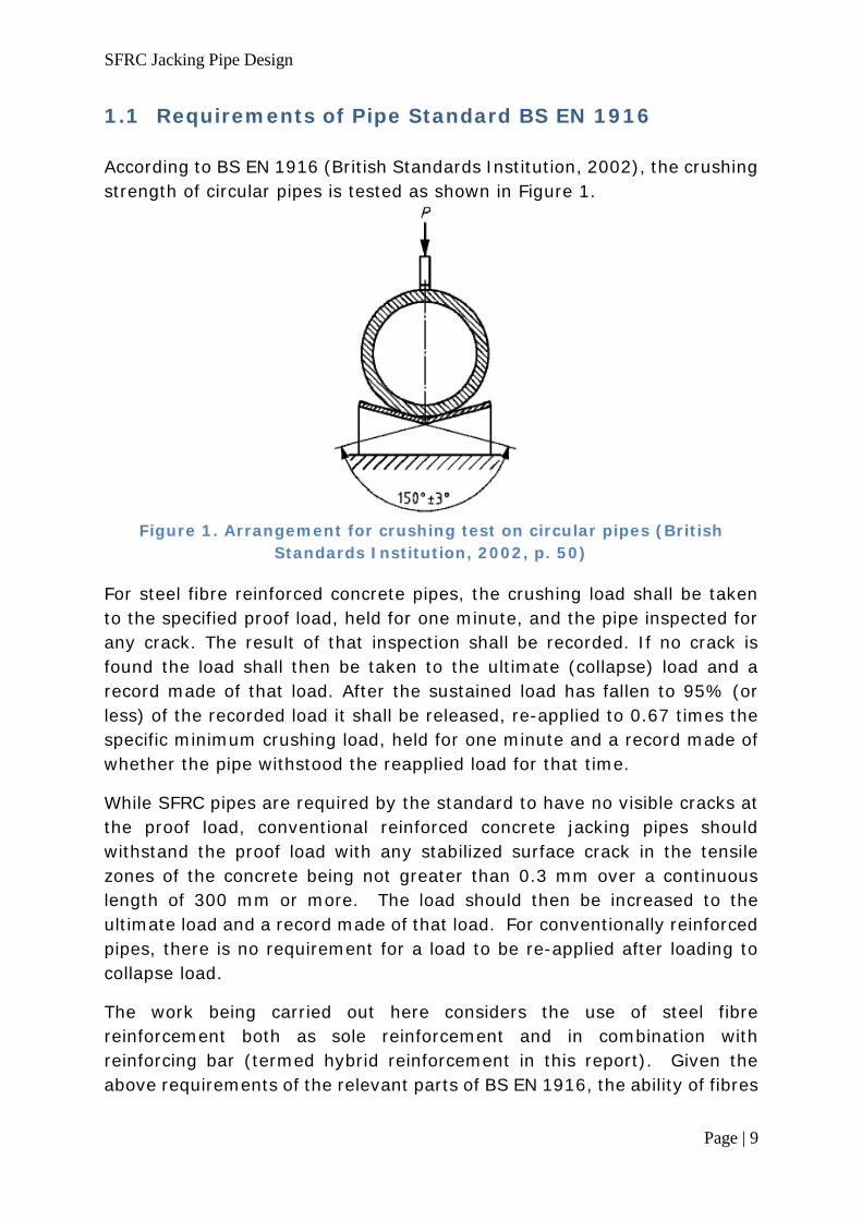
1.1 Requirements of Pipe Standard BS EN 1916 According to BS EN 1916 (British Standards Institution, 2002), the crushing strength of circular pipes is tested as shown in Figure 1.
Figure 1. Arrangement for crushing test on circular pipes (British
Standards Institution, 2002, p. 50)
For steel fibre reinforced concrete pipes, the crushing load shall be taken to the specified proof load, held for one minute, and the pipe inspected for any crack. The result of that inspection shall be recorded. If no crack is found the load shall then be taken to the ultimate (collapse) load and a record made of that load. After the sustained load has fallen to 95% (or less) of the recorded load it shall be released, re-applied to 0.67 times the specific minimum crushing load, held for one minute and a record made of whether the pipe withstood the reapplied load for that time.
While SFRC pipes are required by the standard to have no visible cracks at the proof load, conventional reinforced concrete jacking pipes should withstand the proof load with any stabilized surface crack in the tensile zones of the concrete being not greater than 0.3 mm over a continuous length of 300 mm or more. The load should then be increased to the ultimate load and a record made of that load. For conventionally reinforced pipes, there is no requirement for a load to be re-applied after loading to collapse load.
The work being carried out here considers the use of steel fibre reinforcement both as sole reinforcement and in combination with reinforcing bar (termed hybrid reinforcement in this report). Given the above requirements of the relevant parts of BS EN 1916, the ability of fibres

SFRC Jacking Pipe Design
Page | 10
to reduce crack widths is crucial to this application, whether fibres are used alone or in combination with bar reinforcement.
SFRC Jacking Pipe Design
Page | 11
2 FINITE ELEMENT MODELLING
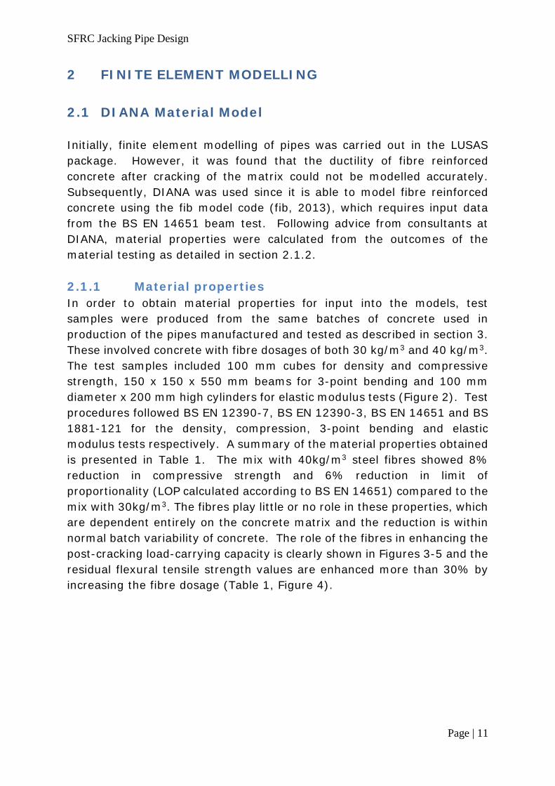
2.1 DIANA Material Model Initially, finite element modelling of pipes was carried out in the LUSAS package. However, it was found that the ductility of fibre reinforced concrete after cracking of the matrix could not be modelled accurately. Subsequently, DIANA was used since it is able to model fibre reinforced concrete using the fib model code (fib, 2013), which requires input data from the BS EN 14651 beam test. Following advice from consultants at DIANA, material properties were calculated from the outcomes of the material testing as detailed in section 2.1.2. 2.1.1 Material properties In order to obtain material properties for input into the models, test samples were produced from the same batches of concrete used in production of the pipes manufactured and tested as described in section 3. These involved concrete with fibre dosages of both 30 kg/m3 and 40 kg/m3. The test samples included 100 mm cubes for density and compressive strength, 150 x 150 x 550 mm beams for 3-point bending and 100 mm diameter x 200 mm high cylinders for elastic modulus tests (Figure 2). Test procedures followed BS EN 12390-7, BS EN 12390-3, BS EN 14651 and BS 1881-121 for the density, compression, 3-point bending and elastic modulus tests respectively. A summary of the material properties obtained is presented in Table 1. The mix with 40kg/m3 steel fibres showed 8% reduction in compressive strength and 6% reduction in limit of proportionality (LOP calculated according to BS EN 14651) compared to the mix with 30kg/m3. The fibres play little or no role in these properties, which are dependent entirely on the concrete matrix and the reduction is within normal batch variability of concrete. The role of the fibres in enhancing the post-cracking load-carrying capacity is clearly shown in Figures 3-5 and the residual flexural tensile strength values are enhanced more than 30% by increasing the fibre dosage (Table 1, Figure 4).

SFRC Jacking Pipe Design
Page | 12
Figure 2. Elastic modulus, compressive strength and flexural strength
tests

SFRC Jacking Pipe Design
Page | 13
Table 1. Mechanical properties of material
30 kg/m3 5D SFRC 40 kg/m3 5D SFRC
Density 2560 kg/m3 2560 kg/m3
Compressive Strength
90.7 MPa 83 MPa
Elastic Modulus 39 GPa 42 GPa
Limit of Proportionality
8.1 MPa 7.4 MPa
Residual strength fr1
5.1 MPa 7.2 MPa
Residual strength fr2
7.3 MPa 9.9 MPa
Residual strength fr3
7.6 MPa 9.9 MPa
Residual strength fr4
6.6 MPa 8.1 MPa
Figure 3. Flexural stress-strain curves of SFRC with different fibre
dosages tested to BS EN 14651

SFRC Jacking Pipe Design
Page | 14
Figure 4. Effect of fibre dosage on tensile and residual flexural strength
of SFRC
Figure 5. Comparing the Load-CMOD behaviour of plain and 5D steel fibre reinforced concrete (Malaki Zanjani, 2014)

SFRC Jacking Pipe Design
Page | 15
2.1.2 Material model The material model implemented for fibre reinforced concrete was based on the fib model (fib, 2013). Following advice from consultants at DIANA, a change to the conversion factors applied to obtain uniaxial tensile stresses from the measured limit of proportionality and residual strengths was made. Based on a model of the BS EN 14651 beam test, appropriate conversion factors (kL, kRi, kRj) were chosen to provide a best fit between the model and the experimental average data (Figure 6). Figure 6a) shows shows this comparison and the final conversion factors were in the range 0.3-0.5. Some models were run in 2D and 3D to verify that the same results were obtained; subsequent modelling was then carried out in 2D.
a) Comparison of reaction load-CMOD curves for DIANA model and
experimental data
b) Crack widths at deflection of 8 mm
Figure 6. Validation of material model

SFRC Jacking Pipe Design
Page | 16
Table 2 shows the final parameters used in the model.
Table 2. Material model
Linear material properties Young’s modulus 42 GPa Poisson’s ratio 0.2 Total strain based crack model Crack orientation Rotating Crack bandwidth specification Govindjee Tensile behaviour Tensile curve Fib fibre reinforced concrete CMOD or strain curve CMOD Stress/CMOD input Tensile strength (kLfL) 3.6 MPa Residual strength (kRifRi) 2.0 MPa Crack mouth opening at fRi 0.21 mm Residual strength (kRjfRj) 3.6 MPa Crack mouth opening at fRj 1.2 mm Ultimate crack mouth opening 7 mm Poisson’s ratio reduction model Damage based Compression curve Elastic behaviour
2.2 Modelling of Jacking Pipes under Crushing Loads Modelling focussed on behaviour of jacking pipes under the crushing test described in section 1.2. Table 3 shows the properties of the pipes modelled. Four different diameter jacking pipes were modelled with different concrete types and reinforcement arrangements.
For all four sizes (450 mm, 600 mm, 900 mm and 1200 mm nominal diameters), the pipes were initially modelled according to the current design with plain concrete (i.e. no fibres) combined with rebar. These models were then used as a benchmark for comparison of new designs to determine whether they would pass or fail the crushing test.
Models were then setup to determine new designs of pipes incorporating SFRC. The main constraint was that the designs must use existing forms to avoid setup costs should SFRC pipes go into production. Focus was on utilising the properties of fibre reinforced concrete to enable bar

SFRC Jacking Pipe Design
Page | 17
reinforcement to be moved for increased cover and/or to reduce the amount of bar reinforcement (through reducing number of cages, diameter and/or increasing spacing of rebar). The aim was to produce designs with fibre reinforced concrete which enabled higher cover and to reduce the amount of rebar if possible to counteract the increased material cost of incorporating fibres.
Therefore, in designing pipes incorporating fibre reinforced concrete, pipes consisting of fibre reinforced concrete with no rebar were modelled at all four diameters (section 2.3.1). Following this, larger diameter pipes (900 mm and 1200 mm) were modelled (section 2.3.2) with fibre reinforced concrete and rebar (termed hybrid reinforcement in this report).

SFRC Jacking Pipe Design
Page | 18
Table 3. Properties of modelled pipes
Pipe size
Fibre dosage (kg/m3)
Bar reinforcement details
No. of cages Spacing Cover
DN
450 0 1 As existing design As existing design
0 None - -
40 None - -
DN
600 0 1 As existing design As existing design
0 None - -
40 None - -
DN
900
0 None - -
40 None - -
0 1 As existing design As existing design
40 1 As existing design As existing design
30 1 Increased spacing Increased to 33 mm
40 1 Increased spacing Increased to 33 mm
40 1 Increased spacing Increased to 40 mm
DN
1200
0 2 As existing design As existing design
0 1 As existing design except outer cage removed
0 1 As existing design except inner cage removed
40 1 As existing design except outer cage removed
40 1 As existing design except inner cage removed
40 2 As existing design As existing design
30 1 As existing design except outer cage removed Increased to 33 mm
40 1 As existing design except outer cage removed Increased to 33 mm
30 1 As existing design except outer cage removed Increased to 40 mm
40 1 As existing design except outer cage removed Increased to 40 mm
Note: Where a cover depth is specified, this is based on the cover that would be achieved in a manufactured pipe and is the cover from the inner wall of the pipe.

SFRC Jacking Pipe Design
Page | 19
2.2.1 Modelling pipes with fibre-only reinforcement
Table 4 shows the horizontal stress (Sxx) and crack width at inner crown along with vertical stress (Syy) at 3 or 9 o’clock positions on the outer wall obtained from the models for the DN450, DN600 and DN900 pipes at the required proof load and ultimate load. These are the critical locations where highest stresses occur. For each pipe size, the outcomes of three models are given: existing design (number of cages=1); pipes with no fibre or bar reinforcement; and fibre reinforcement only.
Table 4. Model outputs for pipes with fibre-only reinforcement
Pipe size
Fibre dosage (kg/m3)
No. of cages
Proof Load Ultimate Load
Sxx (MPa)
Syy (MPa)
Crack width (x10-5 mm)
Sxx (MPa)
Syy (MPa)
Crack width (x10-5 mm)
DN
450 0* 1 3.0 1.2 0 3.5 1.9 11
0 None 3.1 1.2 0 3.5 1.9 11
40 None 3.1 1.2 0 3.6 1.9 8
DN
600 0* 1 3.3 1.6 4 3.6 2.5 27
0 None 3.3 1.6 4 3.6 2.5 28
40 None 3.6 1.6 2 3.6 2.5 26
DN
900
0* 1 3.6 3.1 50 3.5 3.6 168
0 None 3.6 3.1 61 3.6 3.6 372
40 None 3.6 3.1 60 3.6 3.6 372
* denotes existing design
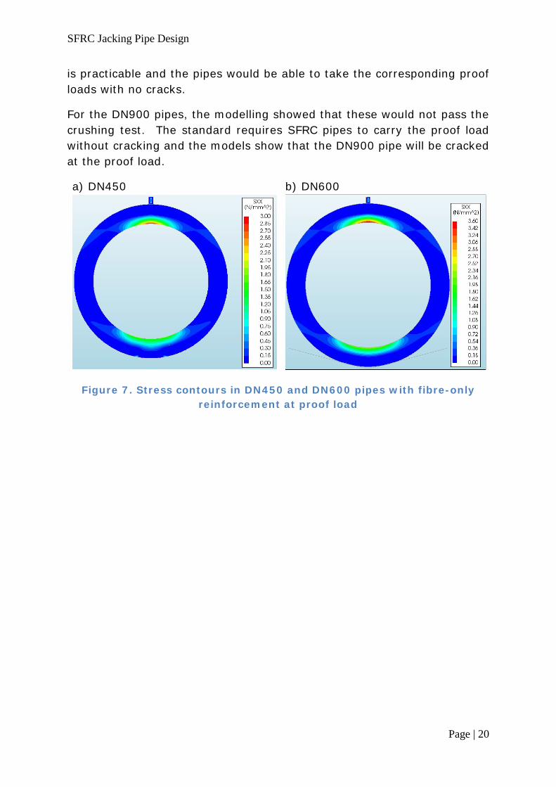
Figure 7 shows the stress contours in horizontal axes for the models of DN450 and DN600 pipes at the proof loads with fibre-only reinforcement. The maximum stress at the crown in DN450 does not reach the first crack strength of 3.6 MPa given in Table 2. In DN600, the maximum stress just reaches this value and the model predicts micro-cracks with maximum 0.02 μm width. The models for these two pipes also showed that the SFRC jacking pipes could withstand the ultimate loads required, with DN450 and DN600 pipes having maximum crack widths at inner crown of 0.08 μm and 0.26 μm respectively.
The modelling of small diameter jacking pipes (DN450 and DN600) showed that replacing the current manufacturing reinforcement cage by steel fibres
SFRC Jacking Pipe Design
Page | 20
is practicable and the pipes would be able to take the corresponding proof loads with no cracks.
For the DN900 pipes, the modelling showed that these would not pass the crushing test. The standard requires SFRC pipes to carry the proof load without cracking and the models show that the DN900 pipe will be cracked at the proof load.
a) DN450
b) DN600
Figure 7. Stress contours in DN450 and DN600 pipes with fibre-only reinforcement at proof load
SFRC Jacking Pipe Design
Page | 21
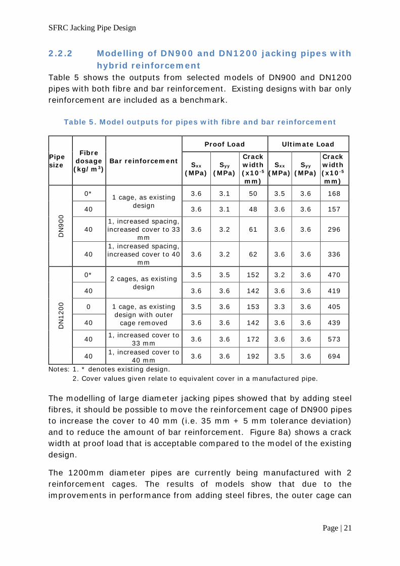
2.2.2 Modelling of DN900 and DN1200 jacking pipes with hybrid reinforcement
Table 5 shows the outputs from selected models of DN900 and DN1200 pipes with both fibre and bar reinforcement. Existing designs with bar only reinforcement are included as a benchmark.
Table 5. Model outputs for pipes with fibre and bar reinforcement
Pipe size
Fibre dosage (kg/m3)
Bar reinforcement
Proof Load Ultimate Load
Sxx (MPa)
Syy (MPa)
Crack width (x10-5 mm)
Sxx (MPa)
Syy (MPa)
Crack width (x10-5 mm)
DN
900
0* 1 cage, as existing design
3.6 3.1 50 3.5 3.6 168
40 3.6 3.1 48 3.6 3.6 157
40 1, increased spacing, increased cover to 33
mm 3.6 3.2 61 3.6 3.6 296
40 1, increased spacing, increased cover to 40
mm 3.6 3.2 62 3.6 3.6 336
DN
1200
0* 2 cages, as existing design
3.5 3.5 152 3.2 3.6 470
40 3.6 3.6 142 3.6 3.6 419
0 1 cage, as existing design with outer
cage removed
3.5 3.6 153 3.3 3.6 405
40 3.6 3.6 142 3.6 3.6 439
40 1, increased cover to 33 mm 3.6 3.6 172 3.6 3.6 573
40 1, increased cover to 40 mm 3.6 3.6 192 3.5 3.6 694
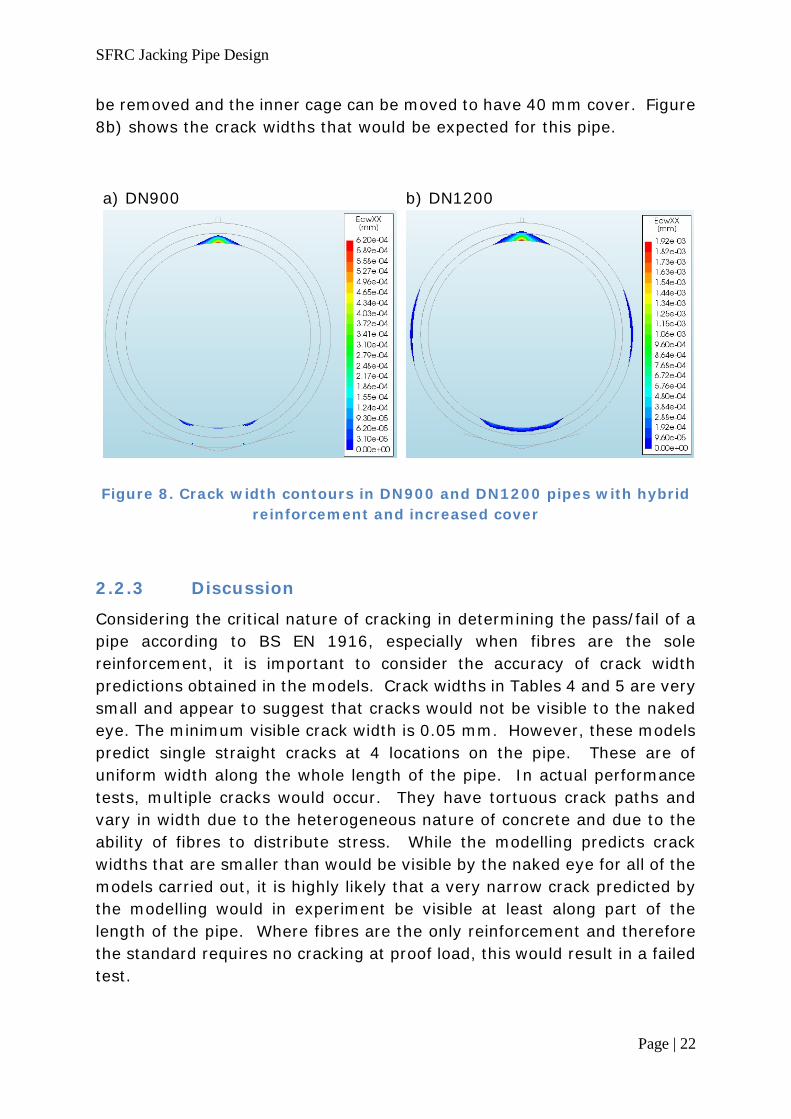
Notes: 1. * denotes existing design. 2. Cover values given relate to equivalent cover in a manufactured pipe. The modelling of large diameter jacking pipes showed that by adding steel fibres, it should be possible to move the reinforcement cage of DN900 pipes to increase the cover to 40 mm (i.e. 35 mm + 5 mm tolerance deviation) and to reduce the amount of bar reinforcement. Figure 8a) shows a crack width at proof load that is acceptable compared to the model of the existing design.
The 1200mm diameter pipes are currently being manufactured with 2 reinforcement cages. The results of models show that due to the improvements in performance from adding steel fibres, the outer cage can
SFRC Jacking Pipe Design
Page | 22
be removed and the inner cage can be moved to have 40 mm cover. Figure 8b) shows the crack widths that would be expected for this pipe.
a) DN900
b) DN1200
Figure 8. Crack width contours in DN900 and DN1200 pipes with hybrid reinforcement and increased cover
2.2.3 Discussion
Considering the critical nature of cracking in determining the pass/fail of a pipe according to BS EN 1916, especially when fibres are the sole reinforcement, it is important to consider the accuracy of crack width predictions obtained in the models. Crack widths in Tables 4 and 5 are very small and appear to suggest that cracks would not be visible to the naked eye. The minimum visible crack width is 0.05 mm. However, these models predict single straight cracks at 4 locations on the pipe. These are of uniform width along the whole length of the pipe. In actual performance tests, multiple cracks would occur. They have tortuous crack paths and vary in width due to the heterogeneous nature of concrete and due to the ability of fibres to distribute stress. While the modelling predicts crack widths that are smaller than would be visible by the naked eye for all of the models carried out, it is highly likely that a very narrow crack predicted by the modelling would in experiment be visible at least along part of the length of the pipe. Where fibres are the only reinforcement and therefore the standard requires no cracking at proof load, this would result in a failed test.

SFRC Jacking Pipe Design
Page | 23
2.3 Suggested Solutions
For DN450 and DN600 pipes, the models show that it would be possible to produce these pipes with fibre reinforcement only. However, the modelling also suggested that these pipes would pass the performance tests without any reinforcement.
For DN900 pipes, the models suggest that by adding fibres, the amount of rebar can be reduced by increasing the spacing and the cover can be increased to 40 mm to produce a pipe able to withstand a harsher exposure class. 40 mm equates to 35 mm + 5 mm tolerance deviation, which achieves an XD2 exposure for 50 years or XD1 exposure for 100 years (British Standards Institution, 2016).
For DN1200 pipes, the models show that the 2 reinforcement cages of the existing design could be reduced to 1, while cover can again be increased to 40 mm.

SFRC Jacking Pipe Design
Page | 24
3 PRODUCTION AND TESTING OF JACKING PIPES
3.1 Concrete Mixture Proportions
The concrete mix proportions used were the standard factory mix design and properties of mixes are presented in Table 6.
Table 6. Concrete mix proportions Class 40/50 designed to comply with EN 206 and BS8500
SSD Weights per m3 Batching Tolerances Cement 430 kg +/- 13
Total Aggregate 1900 kg Grade M Sand 423 kg +/- 13
Dust 107 kg +/- 4 Coarse Aggregate 10mm 392 kg +/- 12 Coarse Aggregate 14mm 978 kg +/- 29
Admixture CR141 3.44 kg +/- 0.17 Water 155 kg +/- 5
a/c ratio: 4.41 : 1 w/c ratio: 0.36 d/a ratio:
6% admix: 0.8% by w.c.
max w/c ratio 0.40 10/a ratio: 21% 14/a
ratio: 51% s/a ratio: 22%
Nominal Plastic Density 2488 kg/m3 +/- 100 Consistence Class S1-
Slump 50 mm +10/- 10
Target mean 28-day strength
60 N/mm2
Concrete Materials Cement Type CEMII/B-V 42.5N
Fine Aggregate Type
0/4mm GF85 Concrete Sand
Type 0/4mm GF85 Dust
Coarse Aggregate Type 6/14mm GC85/15 Basalt Type 4/10mm GC85/15 Basalt
Admixture Type Viscocrete CR141
SFRC Jacking Pipe Design
Page | 25
3.2 Manufacturing of Pipes In total, eight pipes were manufactured by FP McCann at their Alnwick site. These used the standard moulds for jacking pipes with nominal diameters of 900 mm and 1200 mm. The fibre reinforcement was provided by Bekaert 5D® fibres with length of 60 mm and aspect ratio (length/diameter) of 65. Table 7 shows the details of the pipes. All pipes were 2500 mm long. Reference codes for each pipe are defined as follows:
DN900-F40-1R-1
100 mm cubes, 100 mm diameter x 200 mm high cylinders and 150 x 150 x 550 mm beams were cast alongside the pipes to enable the determination of material properties as detailed above in section 2.1.1.
Although the modelling outcomes showed that fibre reinforcement alone would not pass the testing requirements for the large diameter pipes, the testing nevertheless included pipes with bore diameter of 904 mm (DN900) with fibres only. These pipes enabled the investigation of the performance of pipes with fibres as sole reinforcement as well as the effects of varying fibre dosage. These pipes made up 4 of the total with 2 replicate pipes being produced at two different fibre dosages. The pipes were manufactured and tested between May 2016 and July 2016.
The remaining pipes contained a combination of steel fibres at a dosage of 40 kg/m3 (the higher of the two fibre dosages used) and reinforcing bars. For each of the nominal diameters of 900 mm and 1200 mm, the reinforcement cage detail and position was changed from the normal production pipes according to the outcomes of the modelling described above. These pipes therefore have a reduced amount of rebar as well as increased cover. These pipes were manufactured and tested in July/August 2017.
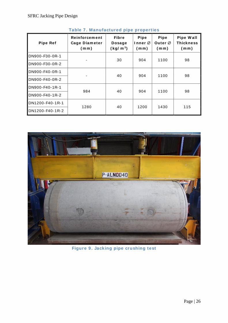
Crushing tests were performed on all 8 pipes in accordance with the requirements of annex C of BS EN 1916:2002, as shown in Figures 1 and 9. Other tests performed on some of the pipes are detailed below and included an end jacking load test according to withdrawn standard BS 5911-120 and a hydrostatic test carried out according to BS EN 1916:2002 Annex E.
Pipe size
Fibre dosage Number of reinforcement cages
Replicate number
SFRC Jacking Pipe Design
Page | 26
Table 7. Manufactured pipe properties
Pipe Ref Reinforcement Cage Diameter
(mm)
Fibre Dosage (kg/m3)
Pipe Inner ∅ (mm)
Pipe Outer ∅ (mm)
Pipe Wall Thickness
(mm)
DN900-F30-0R-1 - 30 904 1100 98
DN900-F30-0R-2
DN900-F40-0R-1 - 40 904 1100 98
DN900-F40-0R-2
DN900-F40-1R-1 984 40 904 1100 98
DN900-F40-1R-2
DN1200-F40-1R-1 1280 40 1200 1430 115
DN1200-F40-1R-2
Figure 9. Jacking pipe crushing test

SFRC Jacking Pipe Design
Page | 27
3.3 DN900 Pipes with Fibre-only Reinforcement
3.3.1 End jacking load test Although not part of the current standard requirements, the end jacking load test on both socket and spigot faces of one of these pipes was conducted. Loading was applied on a 20 mm x 20 mm square block, 100 mm long and set 10 mm below the internal edge of the pipe. The load was measured by a pressure gauge built into the pipe-work of the ram and pump unit. The results showed a positive impact of adding steel fibres in this test. The average joint face strength was 124.8 MPa, compared to a required minimum from BS 5911-120 of 100 MPa. The spalled area of SFRC pipe was observed to be smaller than conventional pipes (Figure 10).
Figure 10. End jacking load test
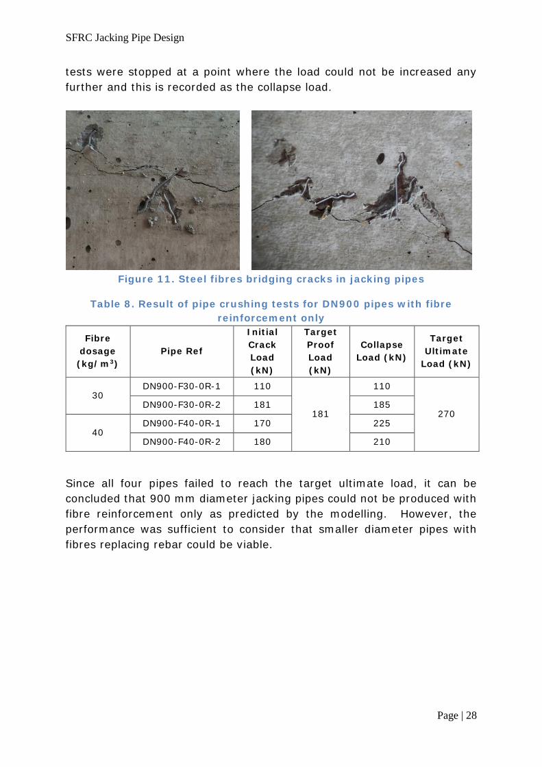
3.3.2 Crushing test The crushing test was performed in accordance with the requirements of annex C of BS EN 1916:2002. The effective length of the concrete being tested was measured at 2500 mm (Figure 9). The pipes are required to withstand a proof load of 181 kN without cracking and 270 kN at ultimate load. The results are recorded in Table 8. Under loading, the initial crack was observed at the non-collar end of the pipe at inside crown (12 o’clock). Cracks then appeared at sides (3 and 9 o’clock) on the outside of the pipe and at invert (6 o’clock) on the inside of the pipe. Steel fibres were observed bridging the cracks along the pipe as shown in Figure 11. All the
SFRC Jacking Pipe Design
Page | 28
tests were stopped at a point where the load could not be increased any further and this is recorded as the collapse load.
Figure 11. Steel fibres bridging cracks in jacking pipes
Table 8. Result of pipe crushing tests for DN900 pipes with fibre reinforcement only
Fibre dosage (kg/m3)
Pipe Ref
Initial Crack Load (kN)
Target Proof Load (kN)
Collapse Load (kN)
Target Ultimate
Load (kN)
30 DN900-F30-0R-1 110
181
110
270 DN900-F30-0R-2 181 185
40 DN900-F40-0R-1 170 225
DN900-F40-0R-2 180 210
Since all four pipes failed to reach the target ultimate load, it can be concluded that 900 mm diameter jacking pipes could not be produced with fibre reinforcement only as predicted by the modelling. However, the performance was sufficient to consider that smaller diameter pipes with fibres replacing rebar could be viable.
SFRC Jacking Pipe Design
Page | 29
3.4 DN900 and DN1200 Jacking Pipes with Hybrid Reinforcement
3.4.1 Hydrostatic test One pipe of each diameter was first tested for watertightness using a hydrostatic test (British Standard Institute, 2002, Annex E) where the pipe is required to withstand a water pressure of 50 kPa (0.5 bar) for 15 minutes without leakage. The DN1200 pipe passed this test. However, the DN900 pipe showed leakage at several locations on the barrel of the pipe. It is unclear why this occurred but visual observation of accompanying beams and cylinders made with the same concrete suggests the possibility that the permeability of the concrete may have been increased due to compaction effects caused by the addition of fibres. It has also been suggested that the leakage was caused by fibres providing moisture pathways or bridges through the concrete. Both effects would be more likely to cause leakage in the DN900 pipes than the DN1200 pipes due to the lower wall thickness. However, fibres acting as bridges would require large number of fibres to be preferentially orientated radially. It is expected, given the wall thickness of the pipe and the length of the fibres, that fibres are more likely to lie tangentially to the pipe walls. If increased permeability is the cause, this could be addressed through modifications to the concrete mix proportions.
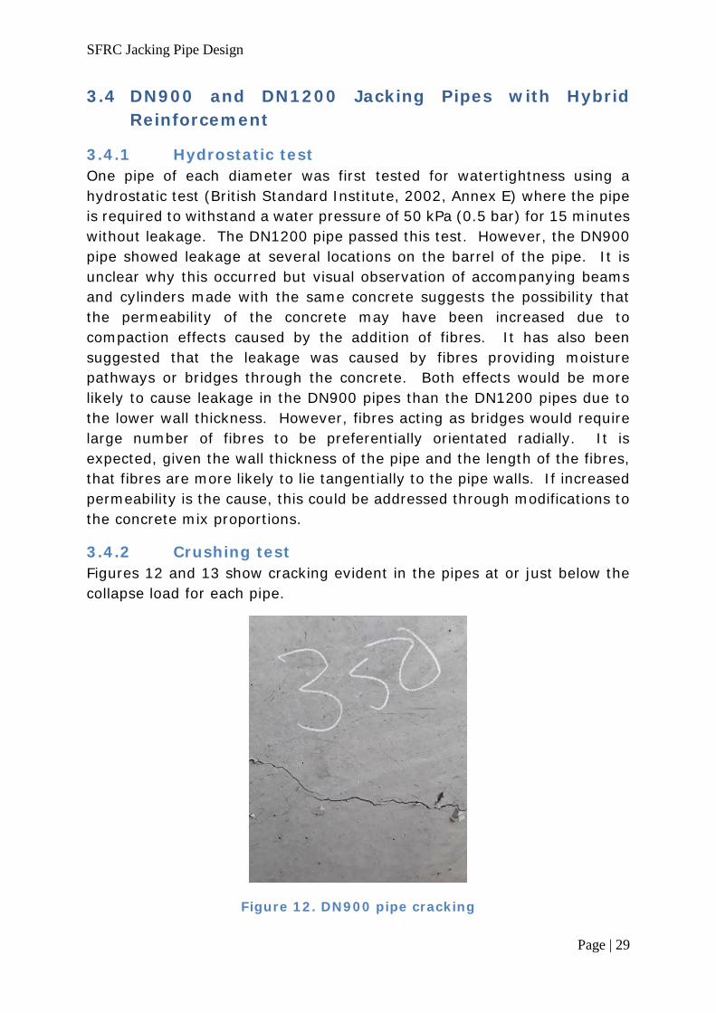
3.4.2 Crushing test Figures 12 and 13 show cracking evident in the pipes at or just below the collapse load for each pipe.
Figure 12. DN900 pipe cracking

SFRC Jacking Pipe Design
Page | 30
Figure 13. DN1200 pipe cracking
The initial crack and collapse loads are recorded in Table 9. Unlike pipes with fibre reinforcement only, pipes with rebar do not need to be uncracked at proof load and were found to have cracks within the required limits at proof load. The pipes with hybrid reinforcement all also had a collapse load exceeding the target ultimate load. Therefore all four of these pipes passed the crushing test, as expected based on the numerical modelling.
Table 9. Results of pipe crushing tests for pipes with hybrid reinforcement
Pipe Ref Initial Crack
Load (kN)
Target Proof
Load (kN)
Collapse Load (kN)
Target Ultimate
Load (kN) DN900-F40-1R-1 210
181 350
270 DN900-F40-1R-2 180 320
DN1200-F40-1R-1 195 241
480 360
DN1200-F40-1R-2 235 510
SFRC Jacking Pipe Design
Page | 31
3.4.3 Economic viability
Based on costs provided by FP McCann and Bekaert, the DN900 and
DN1200 pipe designs obtained by the modelling and tested experimentally
both have an increased cost compared to the existing design. They would
be in the region of 20% more expensive. However, the new designs
represent a significant improvement in durability compared to the existing
designs and meet more demanding exposure classes. The increased cost
is therefore considered viable, since the designs open up the possibility of
sales where increased service life is required.

SFRC Jacking Pipe Design
Page | 32
4 CONCLUSION
The modelling and testing presented in this report shows that fibre reinforced concrete can be utilised in jacking pipes of all four of the diameters investigated, leading to the following solutions in each case:
DN450 and DN600 – pipes containing fibres in place of bar reinforcement are possible.
DN900 – pipes with bar and fibre reinforcement where the spacing of rebar is reduced and cover is increased to 35±5 mm to meet XD1 exposure class for 100 years or XD2 for 50 years.
DN1200 – pipes with bar and fibre reinforcement where the amount of bar reinforcement is reduced by removing the outer reinforcement cage and cover is increased as for DN900 pipes.
In order to ensure compliance with the hydrostatic test, it is recommended that mix proportions be modified to ensure effective compaction of concrete containing fibres.

SFRC Jacking Pipe Design
Page | 33
REFERENCES
Barros, J. A., Taheri, M., Salehian, H., & Mendes, P. J. (2012). A design model for fibre reinforced concrete beams pre-stressed with. Composite Structure 94, 2494-2512.
British Standards Institution (2002). BS EN 1916:2002, Concrete pipes and fittings, unreinforced, steel fibre and reinforced.
British Standards Institution (2007). BS EN 14651:2005+A1:2007, Test method for metallic fibre concrete - Measuring the flexural tensile strength (limit of proportionality (LOP), residual).
British Standards Institution (2014). BS EN 1992-1-1:2004+A1:2014, Eurocode 2: Design of concrete structures. General rules and rules for buildings.
British Standards Institution (2016). BS 8500-1:2015+A1: Concrete – Complementary British Standard toBS EN 206 Method of specifying and guidance for the specifier. London: BSI Standards Limited.
Chapman, D., Metje, N., & Stark, A. (2010). Introduction to tunnel construction. Oxon: Spon Press.
Fib (2013). fib Model Code for Concrete Structures 2010. Wiley-VCH Verlag GmbH & Co. KGaA
Fuente, A., Pujadas, P., Blanco, A., & Ahuado, A. (2012). Experiences in Barcelona with the use of fibres in segmental linings. Tunnelling and Underground Space Technology 27, 60-71.
Ibrahim, I., & Che Bakar, M. (2011). Effects of mechanical properties of industrial steel fibres addition to normal weight concrete. procedia engineering 14, 2616-2626.
Malaki Zanjani, E. (2014). Experimental studies of mechanical properties of concrete reinforced by new 4D and 5D steel fibres. MSc dissertation. University of Portsmouth.


