+ All Categories
Home > Documents > SHUNT ACTIVE POWER FILTER - Shodhgangashodhganga.inflibnet.ac.in/bitstream/10603/17273/12/12-chapter...

SHUNT ACTIVE POWER FILTER - Shodhgangashodhganga.inflibnet.ac.in/bitstream/10603/17273/12/12-chapter...

Date post: 06-Mar-2018
Category:
Upload: doantuong
View: 230 times
Download: 0 times
Share this document with a friend
29
75 CHAPTER 4 SHUNT ACTIVE POWER FILTER Abstract— A synchronous logic based Phase angle control method pulse width modulation (PWM) algorithm is proposed for three phase Shunt Active Power Filter (SAPF) for three- phase systems to ensure low mains current harmonics and high energy efficiency by reducing reactive power consumption, as well as maintaining a constant output DC-bus voltage. Discussed the performance characteristics of SAPF topology with the synchronous logic control algorithm that is based on the angle between the mains and the reference sine wave to control the power factor and to inject a current where each harmonic current has the same amplitude as that of the load current but in opposition of phase. However, this PWM technique greatly simplifies the calculation process and is easier to implement with digital processors. Designed and developed a three-phase SAPF system that is built and tested with the inputs and output with load. The proposed PWM technique can be used in all applications such as Inverters, Filters, UPSs, etc. The Simulation and experimental prototype performance results of a three-phase SAPF with a power output of 3 kVA is presented to validate the proposed control strategy and the results obtained. 4.1 Introduction In the traditional approach, in order to suppress harmonics in power systems, passive power factor correction techniques with line chokes and bulk capacitors are used but they are neither convenient nor economical; they need bulky components and are not adaptive to changing needs. However, the remarkable progress made in the field of the power electronic devices made the systems design for harmonics compensator, named as Active Power Filters
Transcript

75

CHAPTER 4

SHUNT ACTIVE POWER FILTER

Abstract— A synchronous logic based Phase angle control method pulse width modulation

(PWM) algorithm is proposed for three phase Shunt Active Power Filter (SAPF) for three-

phase systems to ensure low mains current harmonics and high energy efficiency by reducing

reactive power consumption, as well as maintaining a constant output DC-bus voltage.

Discussed the performance characteristics of SAPF topology with the synchronous logic

control algorithm that is based on the angle between the mains and the reference sine wave to

control the power factor and to inject a current where each harmonic current has the same

amplitude as that of the load current but in opposition of phase. However, this PWM

technique greatly simplifies the calculation process and is easier to implement with digital

processors. Designed and developed a three-phase SAPF system that is built and tested with

the inputs and output with load. The proposed PWM technique can be used in all applications

such as Inverters, Filters, UPSs, etc. The Simulation and experimental prototype performance

results of a three-phase SAPF with a power output of 3 kVA is presented to validate the

proposed control strategy and the results obtained.

4.1 Introduction

In the traditional approach, in order to suppress harmonics in power systems, passive power

factor correction techniques with line chokes and bulk capacitors are used but they are

neither convenient nor economical; they need bulky components and are not adaptive to

changing needs. However, the remarkable progress made in the field of the power electronic

devices made the systems design for harmonics compensator, named as Active Power Filters

76

(APFs) is a reality. These APFs eliminate the components of power that do not contribute to

the net transfer of energy from the source to the load. New systems and appliances can be

built with the unity power factor and low current harmonics front end rectifiers but large

number of systems that are already in operation need a special attention. Active power filters

can be divided in two classes: series type and shunt type active filters, as defined in [31],

from the system point of view. The combination usage of shunt active and passive filters has

already been in use to compensate large-rated loads input current harmonics. Active Power

Filters also help in meeting the IEEE 519-92, IEC-555 and European EN 61000-3-2/IEC

61000-3-4 standards for allowable harmonic contents of mains.

To prevail over the above drawbacks of the large number of systems that are already in the

field and in operation, power quality improvement filters are included as an inherent part of

the total power network system that produces high efficiency, reduced size and regulated

output. Various types of solutions to Power Quality problems with Active Power Filters are

shown in table 4.1.

Table 4.1: - Active Power Filter Solutions to Power Quality Problems.

Active Power Filter Solutions to Power Quality Problems

Active Filter Connection Load on AC Supply AC Supply to Load

Shunt -Current Harmonic Filtering.

-Reactive current compensation.

-Current unbalance.

-Voltage Flicker.

Nil

Series -Current Harmonic Filtering.

-Reactive current compensation.

-Current unbalance.

-Voltage Flicker.

-Voltage unbalance.

-Voltage sag/swell.

-Voltage unbalance.

-Voltage distortion.

-Voltage interruption.

-Voltage flicker.

-Voltage glitches.

77

An active harmonic power conditioner/compensator/filter is a device that uses at least one

static converter to meet the “harmonic compensation” function. This generic term thus

actually covers a wide range of systems, distinguished by:

• The number of converters used and their association mode,

• Their type (voltage source, current source),

• The global control modes (current or voltage compensation),

• Possible association with passive components (or even passive filters).

(a) (b)

Figure 4.1: - Active Power Filter (a) “shunt-type” and (b)“series type”.

Figure 4.2: - “Series/Parallel” type hybrid filter.

78

The only common feature of these active systems is that they all generate voltages and/or

currents that are in opposition (Phase) to the harmonics generated by non-linear loads. Figure

4.1(a) shows the simplest one that is normally known as “Shunt” (or “Parallel”) type

topology.

The “Series” type active harmonic conditioner shown in Figure 4.1(b) is rarely used. It works

by blocking the upstream harmonic voltage sources to provide better power to a sensitive

load on a troubled power network. However, in practice, this “upstream” technique is of little

interest since:

• The “quality” of the energy at the point of common coupling is satisfactory,

• Insertion of an equipment in “series” mode is not that easy because of the issues like

withstanding short-circuit current,

• It is more useful to look at the actual causes of voltage distortion (harmonic currents)

within the network.

Out of the numerous “Hybrid” alternatives the “Series/Parallel” type solutions have shown in

figure 4.2 the one that combines active and passive filtering is a very effective one for

harmonic cancellation that comes close to the high power converters. Provided that the

equipment is capable of injecting a current at any given time with the same amplitude as that

of the load current but exactly in opposition of phase, at that point of contact (coupling) the

current supplied by the mains is guaranteed to be purely sinusoidal as per the Kirchoff’s law.

The control strategy is to apply a current reference that is equal to all the harmonics content

of the current absorbed by non-linear load, then the current produced by the converter is in

phase opposition to the load and cancels all the harmonics at the point of common coupling

(PCC) as shown in figure 4.3, which is also known as Shunt Active Power Filter (SAPF).

This also comes under the classification of Flexible AC Transmission Systems (FACTS)

which is defined by the IEEE as "a power electronic based system and other static equipment

that provide control of one or more AC transmission system parameters to enhance

79

controllability and increase power transfer capability." The combination of “non linear load

currents plus active power filter currents” forms a linear load current to the mains power

supply. SAPF also supplies the reactive component of the load to make the source current to

be in phase with the voltage.

The SAPF thus forms a current source independent of mains supply impedance as clarified in

[14, 29, 31, 35], and the control algorithm as in [2], with the following characteristics:

• Band-width is sufficient to remove most of the harmonic components from the load

current,

• Response time is such that the harmonic compensation is effective in steady state as well

as in transient state,

• Has enough power to meet all harmonic components. However, all the harmonics

generated by the load are not necessarily compensated in total and permanently.

Provided that these three main objectives are simultaneously met, the SAPF forms an

excellent source solution as it is self-adaptive and there is no risk of interaction with power

network impedances. The aim of SAPF is not to re-phase the mains fundamental voltage and

current components but to make sure the current is linear. So, the insertion of SAPF has no

effect on the displacement power factor. Apart from controlling the harmonics in the source

currents, close to unity power factor ensures that the source is not loaded reactively. Here a

four quadrant, three-phase, six-switch and common link DC bus converter topology used.

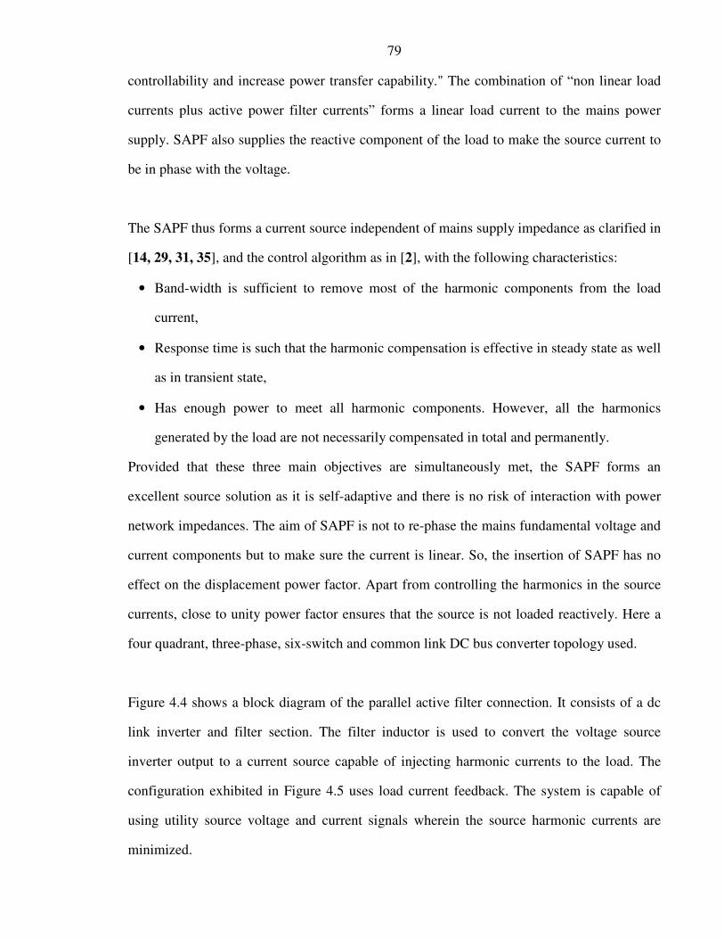
Figure 4.4 shows a block diagram of the parallel active filter connection. It consists of a dc

link inverter and filter section. The filter inductor is used to convert the voltage source

inverter output to a current source capable of injecting harmonic currents to the load. The

configuration exhibited in Figure 4.5 uses load current feedback. The system is capable of

using utility source voltage and current signals wherein the source harmonic currents are

minimized.

Figure 4.3: - Equivalent circuit of Shun

Figure 4.4: - Shows the basic structure of Three

Figure 4.5: - Three

80

(a)

Equivalent circuit of Shunt Active Power Filter, (a) Single line diagram and principle of

compensation (filtering) (b) Three Phase

Shows the basic structure of Three-Phase Shunt Active Power Filter.

Three-Phase and neutral configuration of Shunt active power filter.

(b)

Single line diagram and principle of

Phase Shunt Active Power Filter.

active power filter.

81

The SAPF topology is implemented with six power switches (three legs) as shown in figure

4.5. Shunt active power filter (SAPF) is similar to a PWM unity power factor rectifier by

construction but differ it by a centre tap on the main filter capacitors / batteries which in turn

is connected to the neutral. The control logic types studied as in [3, 19] made improvements

by calculating the load current harmonics in real time by comparing with the fundamental,

which are applied as reference to the inverter control logic in order to cancel the harmonics

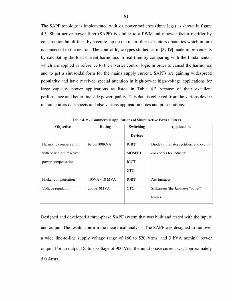
and to get a sinusoidal form for the mains supply current. SAPFs are gaining widespread

popularity and have received special attention in high-power high-voltage applications for

large capacity power applications as listed in Table 4.2 because of their excellent

performance and better line side power quality. This data is collected from the various device

manufacturers data sheets and also various application notes and presentations.

Table 4.2: - Commercial applications of Shunt Active Power Filters

Objective Rating Switching

Devices

Applications

Harmonic compensation

with or without reactive

power compensation

below100KVA IGBT

MOSFET

IGCT

GTO

Diode or thyristor rectifiers and cyclo-

converters for industry

Flicker compensation 100VA ~10 MVA IGBT Arc furnaces

Voltage regulation above10MVA GTO Sinkansen (the Japanese “bullet”

trains)

Designed and developed a three-phase SAPF system that was built and tested with the inputs

and output. The results confirm the theoretical analysis. The SAPF was designed to run over

a wide line-to-line supply voltage range of 160 to 520 Vrms, and 3 kVA nominal power

output. For an output Dc link voltage of 900 Vdc, the input phase current was approximately

5.0 Arms.

82

Experimental prototype system results of three-phase, twelve switches, PWM SAPF that was

designed to deliver an output of 3 kVA power are presented. Details on the formulated

problem design example are presented in section 4.2, including description of a power

section implementation with six power switches and six freewheeling diodes and two

filter/storage capacitors. Details of the SAPF analysis are described in Sections 4.3 including

Input current Analysis. Simulation details are presented in section 4.4. Simulation results are

presented in section 4.5 with nominal input while delivering total of 3 kVA harmonic

compensation. Details on the experimental performance, such as the input currents and

respective harmonics, DC link bus voltage and input voltages are given in Section 4.6. The

overall SAPF system performances with the synchronous logic control implementation are

concluded in Section 4.7.

4.2 Design (Example)

The design and implementation of a shunt active power filter (SAPF) with reduced dc link

voltages as detailed in [35] was studied. Following Flowchart of the generalized design

methodology for SAPF is given in Figure 4.5 (a) and design example is used as an

improvement to the above reference:

1. Choose a suitable PWM switching pattern for the Inverter three phases. Enough lead and

lag angle range accommodated in order to keep the output dc link voltage constant even

under high input voltage fluctuations conditions.

2. Select the switching frequency of the SAPF bridge converter switches (MOSFET, IGBT

or GTO) based on voltage, current and power for the specified kVA rating. The selected

switching frequency is 50 kHz to compensate for higher harmonics of 29th order. So

83

MOSFETs are selected.

3. Select the Free-wheeling diodes for SAPF converter based on the voltage, current and

power for the specified load kVA. Fast Recovery Diodes are selected.

4. Calculate the input filter inductance based on voltage and the kVA rating.

5. Calculate the DC bus link capacitance based on voltage and the kVA rating of converter.

6. Calculate the input main inductance value for the specified output kVA (current) rating,

Lowest input voltage rating and selected constant switching frequency.

Flowchart of the generalized design methodology for SAPF:

I. Determine the required output power rating (Po), input voltage (Vin)

and required efficiency (η) of the system

II. Select a suitable sinusoidal switching pattern for the Inverter three-

phases

III. Determine the required lead and lag angles to keep the harmonic

content low even under high mains voltage and full output load

conditions

IV. Select the suitable Bi-Directional switches (Transistors and Diodes)

based on the type (MOSFET or IGBT), voltage and current based on

the voltage, current and power for the specified load kVA

V. Calculate the input filter inductance based on the voltage and kVA

rating, and desired per unit impedance

VI. Calculate the DC bus link capacitance based on voltage and the kVA

rating of converter

VII. Calculate input main coupling inductance based on the specified

output kVA (current), lowest input voltage and selected switching

frequency

VIII. Verify input current harmonics at various R, RL (fixed) and RL

(variable) loads

IX. Verify system efficiency at various output power levels with R, RL

(fixed) and RL (variable) loads

X. Finalize the design

Fig. 4.5 (a). Flowchart of the

generalized design

methodology for SAPF

Y

N

Y

N

I

II

IV

III

VIII

IX

X

V

VI

VII

84

In this section, the design prototype example of a SAPF is presented which is having the

following specifications:

Table 4.3: - Active Power Filter Specifications (4.8 Arms)

Type APF 3.0 kW

uRS (Nominal) Vrms 3 x 400 ± 15%, 47 to 53 Hz

Power Factor ≥ 0.95

THD of iR ≤10 %

Modulation type Sine PWM

Switching (modulation) frequency 50kHz

Rated VA @ 400 Vac 3.0 kVA

iR 5.0 Aac

Short term over load current in A ac 200% of iR for 0.5 sec. over 60 sec cycle time.

Estimated efficiency η 90

Operating Temp. °C 0 to +40; +40 to + 50 with derating

85

4.3 Shunt Active Power Filter Analysis

The proposed three-phase high-quality Shunt Active Power Filter (SAPF) is shown in figure

4.5. The four wires SAPF consists six power switches (three legs), six power diodes, two

capacitors in the DC side and three line inductances in the ac side. Figure 4.6 illustrates the

phasor diagrams for power exchanges at the Point of Common Coupling (PCC), converter

output current and voltage are shown in all four quadrants of the PQ plane.

Figure 4.6: - Phasor diagram for power exchanges in four quadrant operations.

A. Sinusoidal PWMs for Shunt Active Power Filters

The implementation of a SAPF with synchronous logic based phase angle control algorithm

based PWM is carried out by the same principle as that of a converter. Figure 4.7(a) shows a

reference control wave with frequency Fo and a carrier wave with frequency Fs i.e.,

86

switching frequency. The magnitude of the carrier wave has to be always kept greater than

the reference wave for better harmonics control. The carrier wave generates the gate drive

pulses as shown in Figure 4.7(b) for the power switches sR1 and sR1’ of the SAPF converter

R phase that generates voltage. And for the other two phases S and T, the reference

sinusoidal waves are displaced by an angle 2Π/3 and 4Π/3 respectively.

Figure 4.7(a): – Source Current (Red), Control wave (Green) and Carrier wave (Blue) for R-phase of the Three-

Phase H-Bridge SAPF Converter.

Figure 4.7(b): – Gate drive pulses for R-phase of the Three-Phase H-Bridge SAPF Converter.

87

4.4 System Simulation

The H-Bridge SAPF converter SIMULINK simulation gives DC link voltage of 900 Vdc and

average bridge rectifier DC voltage of 600 Vdc for SAPF converter, at nominal voltage

conditions. The mains current harmonics are much lower than the levels of the statutory

requirements. At various non-linear or/and reactive loads, it is possible to keep the mains

current harmonics low and power factor close to unity for input over voltage situations also.

In order to verify the input current harmonics of SAPF at different load levels while keeping

constant DC link voltage, simulations as shown in figures 4.8(a) and (b) have been

performed. Tabulated results by changing the loads on the output with R, RL (PF-fixed), and

RL (PF-variable) variable type. The control strategy has enough lag and lead angles “δ” to

keep the Dc link voltage stable, while keeping the mains current free of harmonics.

4.4.1 Simulation of SAPF with Synchronous Logic:

The model shown below in figure 4.8(a) gives the Simulation circuit of SAPF and figure

4.8(b) shows Synchronous Logic based Phase angle control scheme. Each leg has two power

switches and two power diodes are connected in parallel. IGBT’s are taken as the power

switches. The output voltage and current is taken as the output on the scope.

4.4.1.1 Model Parameters

These parameters are based on the per unit impedances for the given power level and output

ratings/specifications.

• Source: Voltage (Phase) – 230 Vac, Frequency – 50 Hz, Resistance- 0.1 Ω, Inductance - 1.0 mH

• Bridge Rectifier: Output voltage – 600 Vdc, Capacitance - 1000 µF, Load- R – 200 Ω and L -

0.01 mH

• Converter: Coupling Inductance - 1.0 mH, DC link Voltage – 900 Vdc, Switching Frequency –

50 kHz

88

Figure 4.8(a): - Simulation circuit of Shunt Active Power Filter (SIMULINK).

Figure 4.8(b): - Shunt Active Power Filter Control Scheme (SIMULINK).

89

4.5 System Simulation Results

Simulation studies were carried out to validate the Synchronous Logic based control

algorithm SIMULINK model to generate gate drive PWM for SAPF.

SAPF CONVERTER SYSTEM

The simulation results of SAPF system are shown below in figure 4.9 with Resistive (R)

Load. The three phase reference voltages uNR, uNS, uNT are calculated from the frequency

and amplitude of the source voltages as shown in figure 4.9(a). The control waveforms are

calculated from the load current waveforms and compared with the carrier waveforms to get

the drive signals of the power switches. Figure 4.9(b) shows the Load current, Source current

and converter current, 4.9(c) shows DC Capacitor link voltage, and 4.9(d) shows Bridge

Rectifier load (dc) current and voltage. The simulation and results are with Resistive (R)

Load. The input current is, iNR = 5.47 A (corresponding to 1 kW each phase) at 230 Vac

input voltage. Only harmonics 5th, 7th, 11th, 13th, 17th, 19th, 23rd, 25th and 29th are considered.

Third and its multiples are negligible to consider.

4.5.1 Mains (Source) Voltage and Current

The mains (source) supply voltages and currents of R-Phase, Three-Phase, Four-wire, SAPF

are shown in figure 4.10(a) and figure 4.10(b) respectively.

90

(a)

(b)

(c)

(d) Figure 4.9: – SAPF converter; (a) Voltages (uNR, uNS, uNT) from source voltages, (b) Load current, Source

current and converter current, (c) DC Capacitor link voltage, (d) Bridge Rectifier load (dc) current and voltage.

91

(a)

(b) Figure 4.10: – Source waveforms of Three-Phase, Four wire, SAPF R-Phase; (a) Three Phase Voltages (b) Currents.

4.5.2 Source Current Harmonics

Suitable harmonic computation technique for active power filters as detailed in [45] was

studied. The source current harmonics of R-Phase, Three-Phase, Four wire, SAPF are shown

in figure 10(c).

Figure 4.10(c): – Simulation results source current harmonics of R-Phase Three-Phase Four wire SAPF.

0.000

0.050

0.100

0.150

0.200

0.250

0.300

5th

Harm.

7th

Harm.

11th

Harm.

13th

Harm.

17th

Harm.

19th

Harm.

23rd

Harm.

25th

Harm.

29th

Harm.

100W

200W

400W

600W

800W

1000W

92

Table 4.4: – SAPF Simulation Input current and voltage at different Resistive loads.

Table 4.5: – SAPF Simulation Input current harmonics at different Resistive loads.

93

4.6 Experimental Results

In order to verify the SAPF concept, a prototype of a three-phase four wire Shunt Active

Power filter with proposed synchronous logic based phase angle control with source voltage

and load current sensing was built with following specifications: Maximum output of 5A per

Phase current harmonic compensation.

• Source: Voltage (L-N) – 230 V, Frequency – 50 Hz, Inductance - 1.0 mH

• Bridge Rectifier: Output voltage – 600 Vdc, Capacitance - 1000 µF, Load- R – 120 Ω

and L - 0.01 mH

• Converter: Coupling Inductance - 1.0 mH, DC link Voltage – 900 Vdc, Switching

Frequency – 50 kHz

The real-lab prototype for the three phase with neutral SAPF system configuration is shown

in figure 4.5 is shown in figures, 4.11(a), Logic section and Power sections, 4.11(b),

complete assembly of SAPF. The power supply, some line filters and output load sections are

not shown due to space constraints. Component values are based on the kVA rating, per unit

impedance, switching frequency and output rating. The experimental condition is as follows:

three-phase Source inductance is 1.0 mH; SAPF converter coupling inductance is 1.0 mH;

Bridge rectifier output inductance, 0.01 mH and capacitance, 1000 µF. Six main bi-

directional switches in parallel with six ultra fast recovery diodes used to build three-phase

full bridge SAPF converter. SAPF converter phases uNR, uNS and uNT are implemented

with MOSFETs as shown in figure 4.5. The Bridge rectifier output load resistance is 120

ohms. The switching frequency is 50 kHz. Figure 4.12 shows the experimental waveforms.

Three Phase Input Current waveforms (Ch1 – Ch4) iNR, iNS, iNT and iN when a resistive

load of 3 kW applied on output of bridge rectifier.

94

Figure 4.11(a): – Real-Lab prototype set up of the three-phase four wire SAPF Logic and Power sections.

Figure 4.11(b): – Real-Lab prototype set up of the three-phase four wire SAPF Converter.

Ch1: 3A, Ch2: 3A, Ch3: 3A, Ch4: 3A; Scale: 5 ms; Trigger: Line

Figure 4.12: – Three Phase Source Current waveforms (Ch1 – Ch4) iNR, iNS, iNT and iN at 230 V when total

Resistive Load of 3 kW applied on Bridge Rectifier Output.

95

Readings have been taken in order to verify the utility mains current harmonics at different

load levels. Recorded readings of source current harmonics; bridge rectifier output voltages

and efficiency, by changing the loads on the output with R, RL(fixed PF) and RL (variable

PF) type and presented in figures 4.13(a), 4.14(a), 4.15(a); 4.13(b), 4.14(b), 4.15(b) and 4.16

respectively. The measured power factor was 0.97 when the DC-Link voltage was 900 Vdc.

Bridge rectifier output voltage is 600 Vdc (+300 and -300 referenced to center point) and

currents are multiplied by 50 to make them easily readable. Only harmonics 5th, 7th, 11th, 13th,

17th, 19th, 23rd, 25th and 29th are considered. Third and its multiples are negligible to consider.

The values of the displacement power factor (DPF), power factor (PF), and current total

harmonic distortion (THD), respectively for the load and power supply source are presented

in Table 4.4. The values of THD are for the phase and neutral currents. The values of DPF

and PF are presented to each of the phases.

Table 4.6: – SAPF DPF, PF and currents THD values at Load and source with crest factor loads.

It is confirmed after comparing the results that the SAPF compensates the PF and the

harmonic currents, turning them into near unity and near zero respectively at source supply.

The source current spectrum, rectifier output voltages and current are shown in Figure 4.13

with resistive (R) Load. The input current is, iNR = 5.0 A at 232 Vac input voltage. The

efficiency at rated power is 82%.

96

Table 4.7: –SAPF Input current and voltage at different Resistive loads.

Table 4.8: – SAPF Input current harmonics at different Resistive loads.

97

(a)

(b)

Figure 4.13: - SAPF with Resistive Load, (a) Source current harmonics at different load levels, (b) Bridge

Rectifier output Voltage and Current with 3 kW load.

Figure 4.14 shows the source current spectrum, rectifier output voltages and current with

Resistive and Inductive (RL) Load with a fixed power factor. The input current is, iNR =

5.14 A at 231 Vac input voltage. The efficiency at rated power is 80%.

0.000

0.050

0.100

0.150

0.200

0.250

0.300

0.350

0.400

5th

Harm.

7th

Harm.

11th

Harm.

13th

Harm.

17th

Harm.

19th

Harm.

23rd

Harm.

25th

Harm.

29th

Harm.

100W

200W

400W

600W

800W

1000W

-400

-300

-200

-100

0

100

200

300

400

I-R-Load V1 - R

V2 - R

98

Table 4.9: –SAPF Input current and voltage at different RL loads (Fixed-PF).

Table 4.10: – SAPF Input current harmonics at different RL loads (Fixed-PF).

99

(a)

(b)

Figure 4.14: - SAPF with Resistive and Inductive (RL) Load with a fixed rated power factor, (a) Source current

harmonics at different load levels, (b) Bridge Rectifier output Voltage and Current with 3 kW load.

Figure 4.15 shows the source current spectrum, rectifier output voltages and current with

Resistive and Inductive (RL) Load with variable power factor. The input current is, iNR =

5.08 A at 231 Vac input voltage. The efficiency at rated power is 81%.

0.000

0.050

0.100

0.150

0.200

0.250

0.300

0.350

0.400

0.450

5th Harm.

7th Harm.

11th Harm.

13th Harm.

17th Harm.

19th Harm.

23rd Harm.

25th Harm.

29th Harm.

100W

200W

400W

600W

800W

1000W

-400

-300

-200

-100

0

100

200

300

400

I-RL- (PF-Fixed) V1 - RL-(PF-Fixed)

V2 - RL-(PF-Fixed)

100

Table 4.11: –SAPF Input current and voltage at different RL loads (Variable-PF).

Table 4.12: – SAPF Input current harmonics at different RL loads (Variable-PF).

101

(a)

(b)

Figure 4.15: - SAPF with Resistive and Inductive (RL) Load with variable power factor, (a) Source current

harmonics at different load levels, (b) Bridge Rectifier output Voltage and Current with 3 kW load.

Figure 4.16: - Efficiencies of SAPF with various load levels.

0.000

0.050

0.100

0.150

0.200

0.250

0.300

0.350

0.400

5th Harm.

7th Harm.

11th Harm.

13th Harm.

17th Harm.

19th Harm.

23rd Harm.

25th Harm.

29th Harm.

100W

200W

400W

600W

800W

1000W

-400

-300

-200

-100

0

100

200

300

400

I-RL-(PF-Variable)

V1 - RL-(PF-Variable)

V2 - RL-(PF-Variable)

0

10

20

30

40

50

60

70

80

90

100 200 400 600 800 1000

ƞ R Load

ƞ RL Fixed

ƞ RL Variable

102

The efficiencies shown in figure 4.16 are with Resistive, Resistive and Inductive (RL) Load

with fixed power factor and RL with variable power factor from unity to rated.

Measurements were recorded by changing the loads on the output of the setup. The

efficiency varied based on the type of load and also percentage of the load from 58% to 82%.

4.7 Summary

More reactive power and more current harmonics means more losses, lower efficiency, more

electric energy to be produced and correspondingly more environmental pollution and

particularly more carbon dioxide put in to the atmosphere. Cancellation of harmonics and

reduction of reactive power in the mains represents not only an economic sense but also a

direct solution for sustainable development. A number of possible SAPF were presented. It

was demonstrated that both voltage and current harmonics can be cancelled as well as the

reactive component of the load current by using proper control logic. The phase angle control

was based on specialized logic developed for converter applications, providing a simple and

cost effective solution.

The proposed three-phase, four wire, six switch H-Bridge, SAPF converter was investigated

and simulated; source current distortion that usually generated by diode bridge rectifier and

capacitive filter was controlled. A new three-phase synchronous logic based phase angle

control is introduced and simulations show that it can produce very low DC link voltage

ripple and very low source current harmonics with unity power factor. The resulting input

current harmonics were below the limits of IEC 61000-3-4 standard for various load levels.

Experimental SAPF converter of 1 kVA per phase, with six switches H-Bridge was built to

103

verify the concept. Near unity power factor was measured in all three phases. The source is

having lower current harmonics but more number of conducting devices (Converter and

Rectifier) resulted in lower efficiency. The proposed controller is implemented by sensing

source voltages, load currents and DC link voltage. The SAPF converter controller is very

simple and reliable. The input inductance size and value is reduced when compared to the

passive filter circuit. The experimental results confirm the prototype circuit’s behavior.


Recommended