C I R E D 18 th International Conference on Electricity Distribution Turin, 6-9 June 2005 SHUNT TUNED FILTER ON THE LV SIDE OF DISTRIBUTION SYSTEMS: PERFORMANCE EVALUATION J. R. Macedo Jr, M.Sc J. W. Resende, Ph.D. M. I. Samesima, D.Sc. ESCELSA UFU UFU [email protected]INTRODUCTION Nowadays, the use of modern electronic equipment in residential houses connected to the low-voltage distribution circuits have brought some adverse effects such as overheated transformers, high voltage distortion and low power factor within low voltage customers. In order to mitigate harmonic problems in industries and in medium-voltage distribution systems, the usual way is to adopt shunt passive filters. The main contribution of this paper is to presents an analysis of an unusual application of shunt harmonic filters. That is the use of tuned filters in a Brazilian utility, more precisely, in the low-voltage side of a 13.8/0.22 kV distribution system transformer, which feeds several ordinary home consumers. Another feature of this proposal is that the filter is pole mounted, as illustrated if figure 1. GENERAL CONCEPTS The figure 2 illustrates a voltage harmonic spectrum, which is typical of low-voltage sides of 13.8/0.22 kV distribution system power transformers allocated in urban residential areas. As it can be seen, this spectrum is rich in 5 th harmonic content, which is, in general, due to domestic appliances, such as microcomputers, Compact Fluorescent Lamps, DVD’s, etc. Thus, in order to reduce this harmonic, this paper presents a study in which a 5th harmonic shunt filter is designed and placed in the 220 V side of a distribution system transformer. The reactors [L] of the filter are of the air-core type. The reactors and capacitors are connected as illustrated in figure 3. In this figure, although the capacitors are actually Delta connected, the calculations for the tuned filter are done by transforming this connection into an equivalent wye- connection [3]. Fig. 1. Layout for the tuned filter. 0,0 0,5 1,0 1,5 2,0 2,5 3,0 3,5 2 3 4 5 6 7 8 9 10 11 12 13 14 15 16 17 18 19 20 21 22 23 24 25 THD Harmonic Order Magnitude ( % of Fundamental ) . Fig. 2. Typical voltage harmonic spectrum measured in low-voltage sides of 13.8/0.22 kV distribution system power transformers. CIRED2005 Session No 2
Transcript
CC II RR EE DD 18th International Conference on Electricity Distribution Turin, 6-9 June 2005
SHUNT TUNED FILTER ON THE LV SIDE OF
DISTRIBUTION SYSTEMS: PERFORMANCE EVALUATION
J. R. Macedo Jr, M.Sc J. W. Resende, Ph.D. M. I. Samesima, D.Sc. ESCELSA UFU UFU
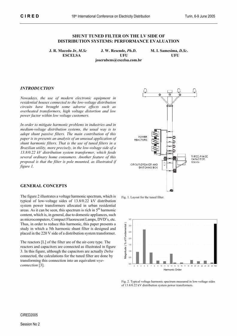
INTRODUCTION Nowadays, the use of modern electronic equipment in residential houses connected to the low-voltage distribution circuits have brought some adverse effects such as overheated transformers, high voltage distortion and low power factor within low voltage customers. In order to mitigate harmonic problems in industries and in medium-voltage distribution systems, the usual way is to adopt shunt passive filters. The main contribution of this paper is to presents an analysis of an unusual application of shunt harmonic filters. That is the use of tuned filters in a Brazilian utility, more precisely, in the low-voltage side of a 13.8/0.22 kV distribution system transformer, which feeds several ordinary home consumers. Another feature of this proposal is that the filter is pole mounted, as illustrated if figure 1. GENERAL CONCEPTS
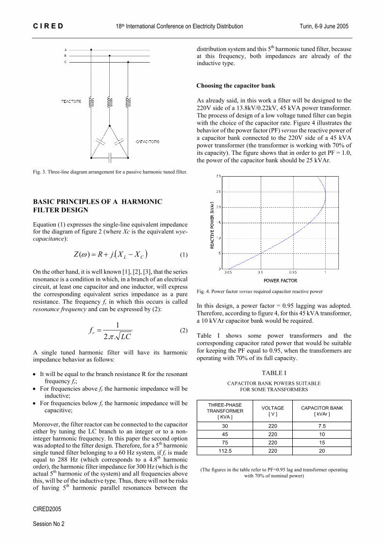
The figure 2 illustrates a voltage harmonic spectrum, which is typical of low-voltage sides of 13.8/0.22 kV distribution system power transformers allocated in urban residential areas. As it can be seen, this spectrum is rich in 5th harmonic content, which is, in general, due to domestic appliances, such as microcomputers, Compact Fluorescent Lamps, DVD’s, etc. Thus, in order to reduce this harmonic, this paper presents a study in which a 5th harmonic shunt filter is designed and placed in the 220 V side of a distribution system transformer.
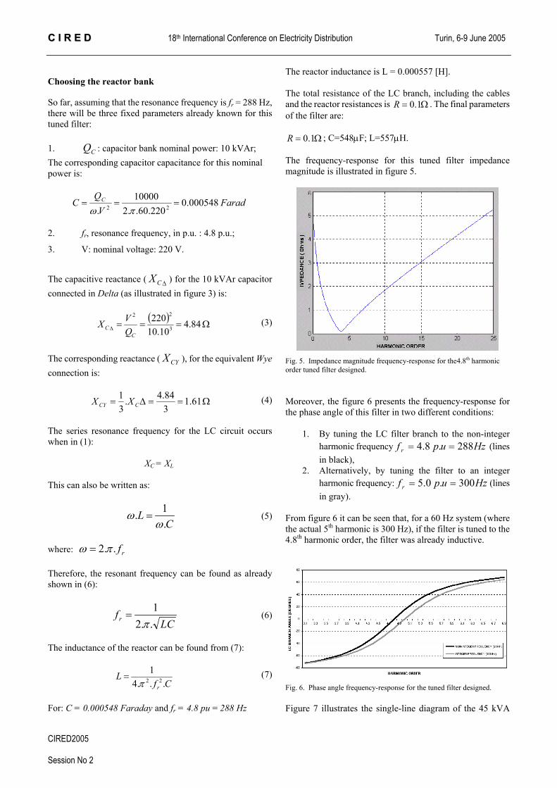
The reactors [L] of the filter are of the air-core type. The reactors and capacitors are connected as illustrated in figure 3. In this figure, although the capacitors are actually Delta connected, the calculations for the tuned filter are done by transforming this connection into an equivalent wye-connection [3].
Fig. 2. Typical voltage harmonic spectrum measured in low-voltage sides of 13.8/0.22 kV distribution system power transformers.
CIRED2005 Session No 2
CC II RR EE DD 18th International Conference on Electricity Distribution Turin, 6-9 June 2005
Fig. 3. Three-line diagram arrangement for a passive harmonic tuned filter.
BASIC PRINCIPLES OF A HARMONIC FILTER DESIGN
Equation (1) expresses the single-line equivalent impedance for the diagram of figure 2 (where Xc is the equivalent wye-capacitance):
( )CL XXjRZ −+= .)(ω (1)
On the other hand, it is well known [1], [2], [3], that the series resonance is a condition in which, in a branch of an electrical circuit, at least one capacitor and one inductor, will express the corresponding equivalent series impedance as a pure resistance. The frequency fr in which this occurs is called resonance frequency and can be expressed by (2):
LCfr ..2
1π
= (2)
A single tuned harmonic filter will have its harmonic impedance behavior as follows:
• It will be equal to the branch resistance R for the resonant
frequency fr; • For frequencies above fr the harmonic impedance will be
inductive; • For frequencies below fr the harmonic impedance will be
capacitive;
Moreover, the filter reactor can be connected to the capacitor either by tuning the LC branch to an integer or to a non-integer harmonic frequency. In this paper the second option was adopted to the filter design. Therefore, for a 5th harmonic single tuned filter belonging to a 60 Hz system, if fr is made equal to 288 Hz (which corresponds to a 4.8th harmonic order), the harmonic filter impedance for 300 Hz (which is the actual 5th harmonic of the system) and all frequencies above this, will be of the inductive type. Thus, there will not be risks of having 5th harmonic parallel resonances between the
distribution system and this 5th harmonic tuned filter, because at this frequency, both impedances are already of the inductive type.
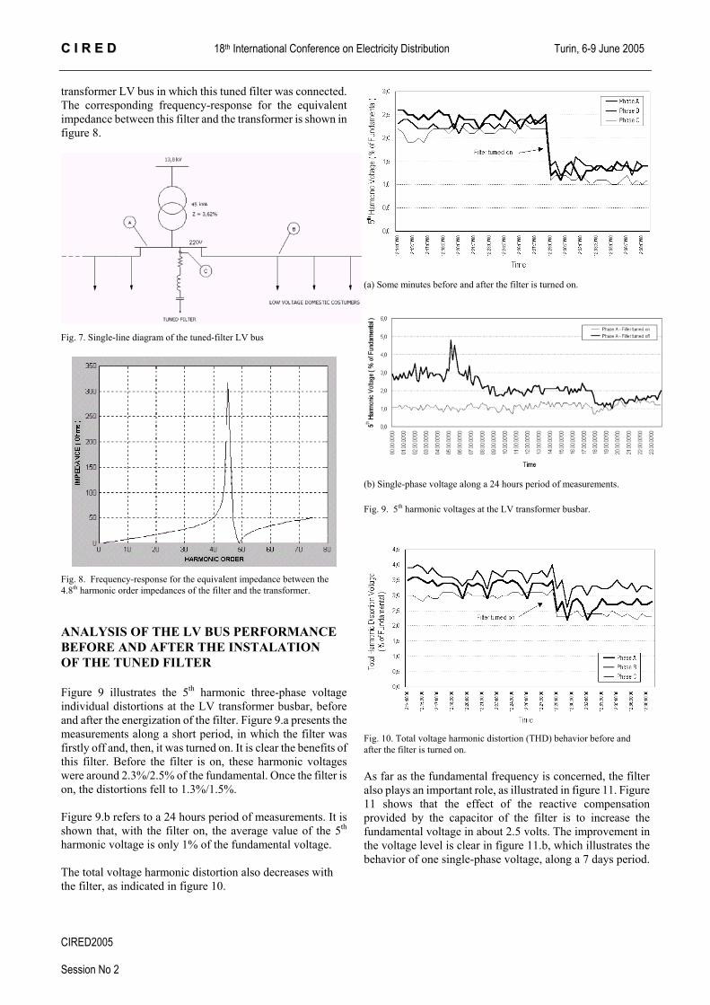
Choosing the capacitor bank As already said, in this work a filter will be designed to the 220V side of a 13.8kV/0.22kV, 45 kVA power transformer. The process of design of a low voltage tuned filter can begin with the choice of the capacitor rate. Figure 4 illustrates the behavior of the power factor (PF) versus the reactive power of a capacitor bank connected to the 220V side of a 45 kVA power transformer (the transformer is working with 70% of its capacity). The figure shows that in order to get PF = 1.0, the power of the capacitor bank should be 25 kVAr.
Fig. 4. Power factor versus required capacitor reactive power In this design, a power factor = 0.95 lagging was adopted. Therefore, according to figure 4, for this 45 kVA transformer, a 10 kVAr capacitor bank would be required.
Table I shows some power transformers and the corresponding capacitor rated power that would be suitable for keeping the PF equal to 0.95, when the transformers are operating with 70% of its full capacity.
TABLE I CAPACITOR BANK POWERS SUITABLE
FOR SOME TRANSFORMERS
THREE-PHASE TRANSFORMER
[ KVA ]
VOLTAGE [ V ]
CAPACITOR BANK [ kVAr ]
30 220 7.545 220 1075 220 15
112.5 220 20
(The figures in the table refer to PF=0.95 lag and transformer operating with 70% of nominal power)
CIRED2005 Session No 2
CC II RR EE DD 18th International Conference on Electricity Distribution Turin, 6-9 June 2005
Choosing the reactor bank
So far, assuming that the resonance frequency is fr = 288 Hz, there will be three fixed parameters already known for this tuned filter:
1. : capacitor bank nominal power: 10 kVAr; CQThe corresponding capacitor capacitance for this nominal power is:
FaradV
QC C 000548.0
220.60..210000
. 22 ===πω
2. fr, resonance frequency, in p.u. : 4.8 p.u.;
3. V: nominal voltage: 220 V.
The capacitive reactance ( ) for the 10 kVAr capacitor connected in Delta (as illustrated in figure 3) is:
∆CX
( )
Ω===∆ 84.410.10
2203
22
CC Q
VX (3)
The corresponding reactance ( ), for the equivalent Wye connection is:
CYX
Ω==∆= 61.1384.4.
31
CCY XX (4)
The series resonance frequency for the LC circuit occurs when in (1):
XC = XL This can also be written as:
CL
.1.
ωω = (5)
where: rf..2 πω = Therefore, the resonant frequency can be found as already shown in (6):
LCfr ..2
1π
= (6)
The inductance of the reactor can be found from (7):
CfL
r ...41
22π= (7)
For: C = 0.000548 Faraday and fr = 4.8 pu = 288 Hz
The reactor inductance is L = 0.000557 [H]. The total resistance of the LC branch, including the cables and the reactor resistances is . The final parameters of the filter are:
Ω= 1.0R
Ω= 1.0R ; C=548µF; L=557µH.
The frequency-response for this tuned filter impedance magnitude is illustrated in figure 5.
Fig. 5. Impedance magnitude frequency-response for the4.8th harmonic order tuned filter designed.
Moreover, the figure 6 presents the frequency-response for the phase angle of this filter in two different conditions:
1. By tuning the LC filter branch to the non-integer
harmonic frequency (lines in black),
Hzupf r 288. 8.4 ==
2. Alternatively, by tuning the filter to an integer harmonic frequency: (lines in gray).
Hzupf r 300. 0.5 ==
From figure 6 it can be seen that, for a 60 Hz system (where the actual 5th harmonic is 300 Hz), if the filter is tuned to the 4.8th harmonic order, the filter was already inductive.
Fig. 6. Phase angle frequency-response for the tuned filter designed. Figure 7 illustrates the single-line diagram of the 45 kVA
CIRED2005 Session No 2
CC II RR EE DD 18th International Conference on Electricity Distribution Turin, 6-9 June 2005
transformer LV bus in which this tuned filter was connected. The corresponding frequency-response for the equivalent impedance between this filter and the transformer is shown in figure 8.
Fig. 7. Single-line diagram of the tuned-filter LV bus
Fig. 8. Frequency-response for the equivalent impedance between the 4.8th harmonic order impedances of the filter and the transformer.
ANALYSIS OF THE LV BUS PERFORMANCE BEFORE AND AFTER THE INSTALATION OF THE TUNED FILTER Figure 9 illustrates the 5th harmonic three-phase voltage individual distortions at the LV transformer busbar, before and after the energization of the filter. Figure 9.a presents the measurements along a short period, in which the filter was firstly off and, then, it was turned on. It is clear the benefits of this filter. Before the filter is on, these harmonic voltages were around 2.3%/2.5% of the fundamental. Once the filter is on, the distortions fell to 1.3%/1.5%. Figure 9.b refers to a 24 hours period of measurements. It is shown that, with the filter on, the average value of the 5th harmonic voltage is only 1% of the fundamental voltage.
The total voltage harmonic distortion also decreases with the filter, as indicated in figure 10.
(a) Some minutes before and after the filter is turned on.
(b) Single-phase voltage along a 24 hours period of measurements.
Fig. 9. 5th harmonic voltages at the LV transformer busbar.
Fig. 10. Total voltage harmonic distortion (THD) behavior before and after the filter is turned on. As far as the fundamental frequency is concerned, the filter also plays an important role, as illustrated in figure 11. Figure 11 shows that the effect of the reactive compensation provided by the capacitor of the filter is to increase the fundamental voltage in about 2.5 volts. The improvement in the voltage level is clear in figure 11.b, which illustrates the behavior of one single-phase voltage, along a 7 days period.
CIRED2005 Session No 2
CC II RR EE DD 18th International Conference on Electricity Distribution Turin, 6-9 June 2005
(a) Some minutes before and after the filter is turned on
(b) Single-phase voltage along 7 days of measurements
Fig. 11. Fundamental voltage behavior before and after the filter is on. The power factor (PF) is also improved with the capacitor bank of the filter, as shown in figure 12. Before the capacitor bank is on, the PF used to be around 0.80 (lag). Once the capacitor bank is energized, the PF reaches 0.96.
Fig. 12. Power factor behavior before and after the filter is turned on.
The harmonic current spectrum in the filter branch is shown in figure 13. As expected, the highest content is the 5th harmonic one.
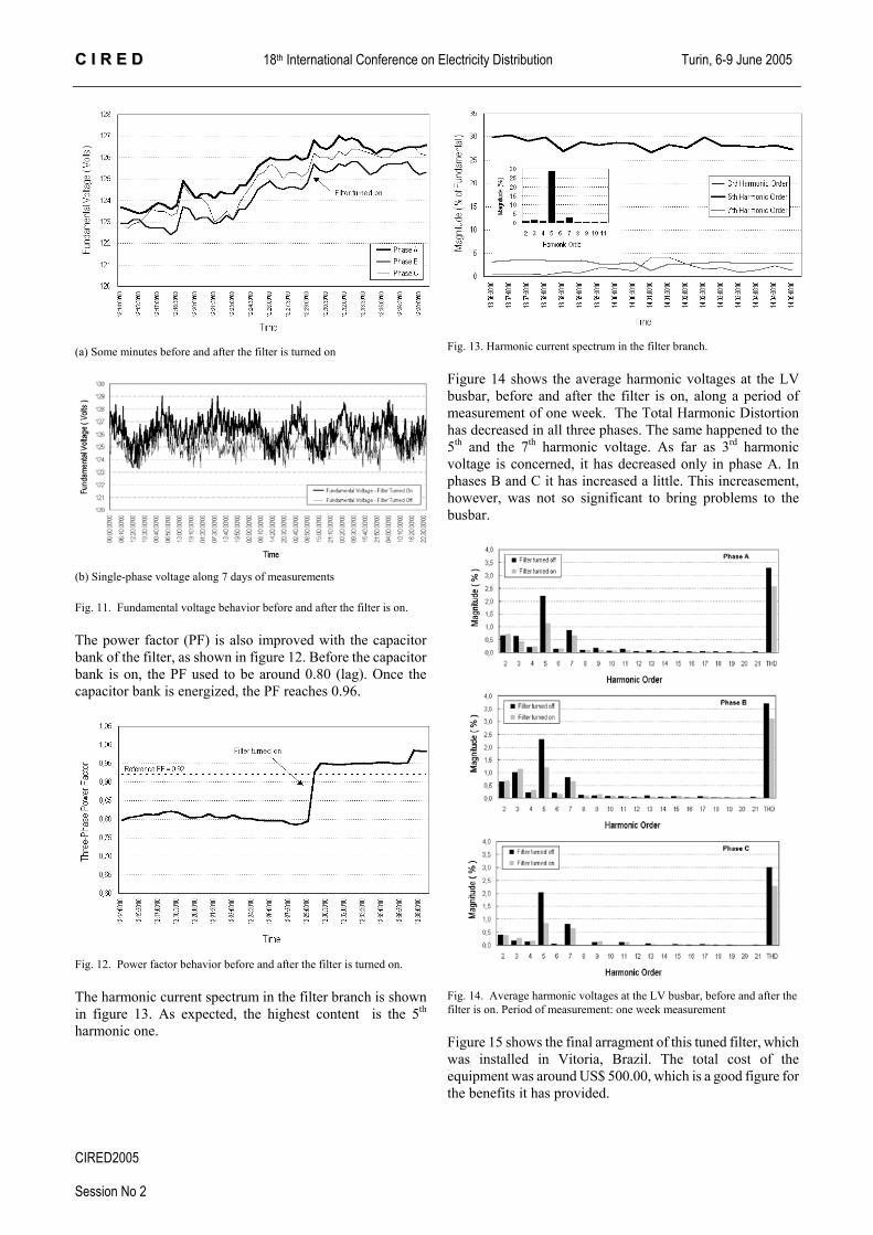
Fig. 13. Harmonic current spectrum in the filter branch. Figure 14 shows the average harmonic voltages at the LV busbar, before and after the filter is on, along a period of measurement of one week. The Total Harmonic Distortion has decreased in all three phases. The same happened to the 5th and the 7th harmonic voltage. As far as 3rd harmonic voltage is concerned, it has decreased only in phase A. In phases B and C it has increased a little. This increasement, however, was not so significant to bring problems to the busbar.
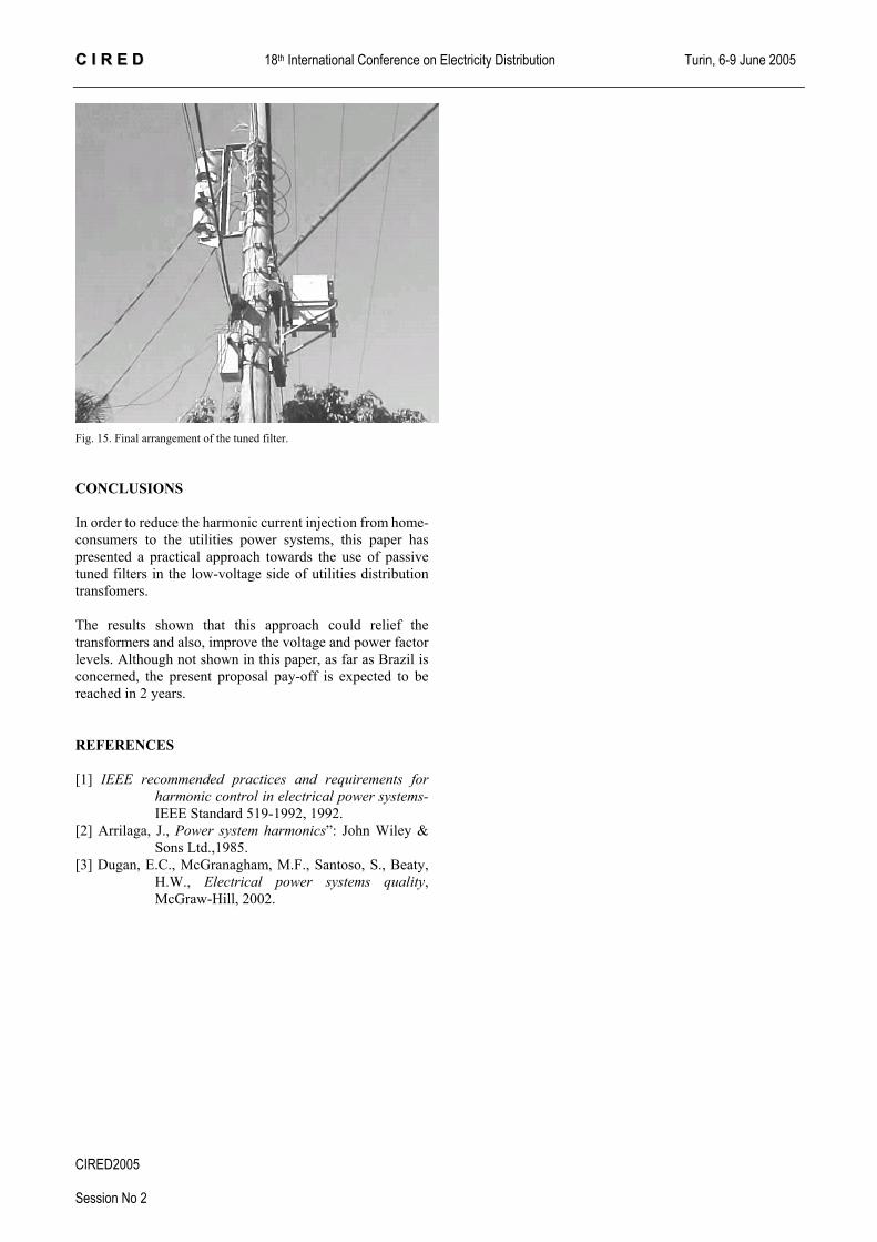
Fig. 14. Average harmonic voltages at the LV busbar, before and after the filter is on. Period of measurement: one week measurement Figure 15 shows the final arragment of this tuned filter, which was installed in Vitoria, Brazil. The total cost of the equipment was around US$ 500.00, which is a good figure for the benefits it has provided.
CIRED2005 Session No 2
CC II RR EE DD 18th International Conference on Electricity Distribution Turin, 6-9 June 2005
Fig. 15. Final arrangement of the tuned filter.
CONCLUSIONS In order to reduce the harmonic current injection from home-consumers to the utilities power systems, this paper has presented a practical approach towards the use of passive tuned filters in the low-voltage side of utilities distribution transfomers.
The results shown that this approach could relief the transformers and also, improve the voltage and power factor levels. Although not shown in this paper, as far as Brazil is concerned, the present proposal pay-off is expected to be reached in 2 years.
REFERENCES
[1] IEEE recommended practices and requirements for harmonic control in electrical power systems- IEEE Standard 519-1992, 1992.
[2] Arrilaga, J., Power system harmonics”: John Wiley & Sons Ltd.,1985.
[3] Dugan, E.C., McGranagham, M.F., Santoso, S., Beaty, H.W., Electrical power systems quality, McGraw-Hill, 2002.