SIDE BY SIDE RS265 LAWP RS265 LABP RS267 LABP RS267 LASH RS269 LARS REFRIGERATOR REFRIGERATOR PRODUCT FEATURE · LED DISPLAY · LONG HANDLE DESIGN · FASTER COOLING TIMES · IMPROVED EVEN COOLING
Transcript
SIDE BY SIDERS265 LAWPRS265 LABPRS267 LABPRS267 LASHRS269 LARS
REFRIGERATOR
REFRIGERATOR PRODUCT FEATURE
· LED DISPLAY
· LONG HANDLE DESIGN
· FASTER COOLING TIMES
· IMPROVED EVEN COOLING
ttibbo
Text Box
SAM0074
IMPORTANT SAFETY NOTICEThe service guide is for service men with adequate backgrounds ofelectrical, electronic, and mechanical experience. Any attempt to repaira major appliance may result in personal injury and property damage.The manufacturer or dealer cannot be responsible for the interpretationof this information.
SAMSUNG ELECTRONICS AMERICA, INC.Technical Service Guide
Copyright 2005
All rights reserved. This service guide may not be reproduced in whole or inpart in any form without written permission from the SAMSUNG ELECTRONICSCompany.
12. SAFETY INSTRUCTIONS ON SERVICE ······················84
13. REFERENCE INFORMATION ···························· 90
4
1. PRECAUTIONS(SAFETY WARNINGS)
Pull the power plug out before for the change or repair of electric parts.→ Be careful the electric shock.
When exchanging the parts, use the correct parts.→ Check the model name, rating voltage, rating current, running
temperature symbols.
When troubleshooting, connect firmly the types of harness.→ Make not to be separated when some power is imposed.
Check the traces of water infiltration at the electric parts.→ If there is a trace of water infiltration, exchange or tape the parts.
Check the assemble status of parts after troubleshooting.→ It should be done indiscriminately as before the repair.
Check the use circumstance of refrigerator.→ If the refrigerator is installed at the place that is damp or wet, or
status of installation is unstable, change the installation place.
Do earth in case of need.→ Particularly, Be sure to earth when there is a risk of an electric
leakage by humidity or wetness.
Do not use multi plugs in a plug socket at the same time.Check if the power cord and socket is damaged, pressed, squeezed, or fired.
→ If the plug or plug socket is damaged, repair or exchange that immediately.
Do not repair the refrigerator by user himself.
Do not store other materials except the foods.→ Drugs or scientific materials : difficult to keep precise temperature.→ The inflammables(alcohol, benzene, ether, LP gas, butane gas etc.):
have risk of explosion.
5
1. PRECAUTIONS(SAFETY WARNINGS)
Read all instructions before repairing the product and follow the instructionsin order to prevent danger or property damage.
CAUTION/WARNING SYMBOLS DISPLAYED SYMBOLS
Indicates that adanger of deathor serious injuryexists.
Indicates that a riskof personal injuryor material damageexists.
means “Prohibition”.
means “Do not disassemble”.
means “No contact”.
means ”The things to be followed”.
means “Earth to prevent Electricshock”.
means “Power cord should beunplugged from the consent”
Pull the power plug out toexchange the interior lampof the refrigerator.
It may cause electric shock.
Warning
Warning & Caution
Caution
Unplug
Use the rated componentson the replacement.Check the correct model, rated
voltage, rated current, operatingtemperature and so on.
On repair, make sure that thewires such as harness arebundled tightly.Bundle tightly wires in order not to be
detached by the external force and then notto be wetted.
Check if there is any trace indicating the permeation of water.If there is that kind of trace, change
the related components or do thenecessary treatment such as tapingusing the insulating tape.
After repair, check theassembled state of components.It must be in the same assembled state
when compared with the state beforedisassembly.
On repair, remove completely dustor other things of housing parts,harness parts, and check parts.Cleaning may prevent the possible fire by
tracking or short.
Ratedcomponents
6
1. PRECAUTIONS(SAFETY WARNINGS)
Please let users know following warnings & cautions in detail.
Do not allow users to put bottles orkinds of glass in the freezer.
Freezing of the contents may inflict a wound.
Do not allow users to store narrowand lengthy bottles or foods in asmall multi-purpose room.It may hurt you when refrigerator door is
opened and closed resulting in falling stuffdown.
Do not allow users to storepharmaceutical products, scientificmaterials, etc., in the refrigerator.The products which temperature control
should not be stored in the refrigerator.
Do not allow users to storearticles on the product.Opening or closing the door may cause
things to fall down, with may inflict awound.
Prohibition Prohibition Prohibition
Prohibition
Warning & Caution
Do not allow users todisassemble, repair or alter.It may cause fire or abnormal
operation which leads to injury.
Do notdisassemble
Do not allow users to insert thepower plugs for many productsat the same time.May cause abnormal generation of
heat or fire.
Prohibition
Do not allow users to bend thepower cord with excessive forceor do not have the power cordpressed by heavy article.May cause fire.
Do not allow users to install therefrigerator in the wet place orthe place where water splashes.Deterioration of insulation of electric
parts may cause electric shock or fire.
Make sure of the earth.
If earthing is not done, it will cause breakdown and electric shock.
Earth
7
2. PRODUCT SPECIFICATIONS
2-1) Introduction of main function ·····························8
2-3) Interior Views and Dimensions····························· 10
2-4) Model Specification &Comparison Chart ······················· 11
2-5) Model Specification &Comparison Chart ······················· 12
2-6) Dimensions of Refrigerator (Inches)·························· 15
2-7) Optional Material Specification····························· 16
2-8) Refrigerant Route in Refrigeration cycle ························· 17
2-9) Cooling Air Circulation ·································· 18
8
2. PRODUCT SPECIFICATIONS
A newly developed SAMSUNG side by side refrigerator in 2005 has the following characteristics.
1) Twin Cooling System The refrigerator and the freezer have two
evaporators. Given this independent system, the freezer and the refrigerator are cooled individually asrequired and are, therefore, more efficient. Food odor from the refrigerator does not affect food in the freezer due to separate air flow circulation.
2) Multi-Flow System Cool air circulates through multiple vents on every
shelf level. This provides even distribution of coolinginside cabinets to keep your food fresh longer.
3) Xtra SpaceTM
Vertical room next to the ice maker in the freezerprovides space for pizza etc.
4) Door Alarm Beep sound reminds you the door is open.
5) Xtra FreshTM
Optimized humidity control keeps vegetables & fruits fresh.
6) Deodorizer Reusable twin deodorizers keep the refrigerator air
fresh and odor free.
7) CoolSelect ZoneTM Drawer(RS267, RS269) User can select Quick Cool, Thaw, for quickly chill
items, thaw items. Select Soft freeze, Chill or Cool to control the temperature of the drawer.
2-1) Introduction of main function
9
2-2) Specifications
2. PRODUCT SPECIFICATIONS
Defrost Control From 24 to 32 hrsDefrost Thermistor(502AT) 50(off) Electrical Rating AC115V 60Hz 11.6 AmpsMaximum Current Leakage 0.25 mAMaximum Ground Path Resistance 0.1 OhmEnergy Consumption KWH/mo.
When the system power is initally engaged, the default set temperature are -4 for the freezer and 38 for the setrefrigerator, respectively. The numbers shown on the digital display panel stand for the actual compartmentstemperatures. When the compartment temperatures go down, so do the numbers on the display panel, and finally theyreach the set temperatures. Once the system is stabilized, the display temperatures are the set temperature.
1) Freezer Temperature Control.To select a set temperature, press the Freezer Temp. button. The display shows the set temperature from -14 to 8 in sequence.
2) Quick Ice Freezer Temperature ControlInterior Temperature of the freezer will be controlled with -14 degrees Fahrenheit until the ice bucket is filled up withice cubes. When the ice bucket is filled up with ice cubes, the freezer will run with original set temperature. Also,whenever the ice bucket is released from being filled with ice cube, the freezer will repeatto be controlled with -14 degrees Fahrenheit. But if you select "Ice Off, the freezer always will be controlled withoriginal set temperature.
3) Refrigerator Temperature Control.To select a set temperature, press the Fridge Temp. button. The display shown the set temperature from 34 to 46 in sequence.
note) Because of the temperature sensor sensivity, the refrigerator can be under and/or over cooled when the air flow is blocked by stored foods. (Temperature range of the sensor : 15∼80)In the event of a power failure, if the freezer temperature is maintained lower than 41, the last selected set temperature and functions memorized in EEPROM will be restored when the power is on.
for RS265LA
for RS267LARS269LA
3-2) Temperature Control Function
21
3. OPERATING INSTRUCTIONS & INSTALLATION
3-3) Power Freeze and Power Cool Functions
3-4) Child Lock Function
Select the Power Freeze or Power Cool buttons separately. These buttons are toggled ON and OFF and the indicators as well. Although you select Power Freeze or Power Cool, the set temperatures in the freezer and refrigerator are not
changed. The set temperatures for the compartments can be changed while these functions are in use.
1) Power Freeze function1-1) When you press the Power Freeze button, the LED indicator lights right away, but there is 10 seconds lag time to
an actual operation. When this button is pressed again, the Power Freeze function stops and the indicator is offimmediately .
1-2) If you select Power Freeze, both the compressor and the freezer fan run for 2.5 hours continuously.1-3) During Power Freeze, the freezer retains the current settings.1-4) When Power Freeze expires, the indicator goes off and the freezer set temperature will be restored.
2) Power Cool function2-1) Power Cool operation and the indicator work exactly same as the Power Freeze function.2-2)When Power Cool is selected, COMP and Refrigerator Fan operate continuously until the refrigerator reaches
25. This function will be terminated after 2 ½ hr running.
3) When you select Power Freeze and Power Cool togetherEach function works at the same time. The COMP and Freezer Fan run continuously and the Refrigerator Fan runsuntil 25in the refrigerator.
4) Initial Power-On4-1) When the freezer and the refrigerator temperatures are higher than 14 and 50, respectively, if Power
Freeze is selected, then the Refrigerator Fan will be off. If Power Cool is selected, then the FreezerFan will be off.
4-2) When both functions are selected, there is no benefit of fast cooling for each compartment.
When the child lock button is pressed for 3 seconds, the child lock indicator is on with an audible tone.
-When it is locked, no function commands except the Ice type button.
-This function will prevent accidental setting that may be caused by children or pets.
-To unlock the setting functions, press this button for 3 seconds again.
22
3. OPERATING INSTRUCTIONS & INSTALLATION
3-5) Ice & Water Dispenser Function
3-6) C-Fan Motor Delay Function of the Machine Compartment
3-7) CoolSelect ZoneTM Function (RS267LA,RS269LA)
Among several ice-maker functions, the ice extraction function is performed by mechanical system. Only the relaycontrol for a cubed-ice dispensing and the SSR control for the ice chute door are performed electronically.
1) Select Cubed/Crushed/Ice-off function1-1) The Ice Type button selects Cubed/Crushed/Ice-off options in sequence.1-2) A default setting is Cubed option.1-3) If Cubed ice is selected, the Crushed ice bypass solenoid and the geared motor will allow Cubed ice to by pass
the ice Crusher.1-4) If Ice-off is selected, the ice maker will stop working. This option will be terminated when Cubed and Crushed
options are selected.
1-5) The ice chute door must remain open for 5 seconds after dispensing ceases. After this 5 seconds delay, SSR willbe controlled to shut the ice chute door.
2) Water Dispenser function2-1) To dispense water, depress the water dispenser lever located in the dispenser recess.2-2) When the lever is depressed, the water solenoid valve located in the machine compartment is open to flow water.2-3) There is no electronic control function for this option.
According to the ambient temperature, the condenser fan located in the machine compartment is operated withdifferent modes.
To select this function, open the refrigerator door and press the button on the control panel of CoolSelect Zone TM
drawer. When the CoolSelect ZoneTM function is selected, the damper inside fan ductwork is open. So the refrigerator cooling
is performed first, then the damper is closed to control the CoolSelect ZoneTM temperature.
Note) When the Ice-off indicator is on, only Cubed ice will be dispensed from the ice bucket.
Caution) Do not force to close the ice chute door. Try to dispense some more ice again to work it automatically.
Ranges of ambient temp.Above 6661 ~ 65Below 60
Condenser-Fan is ON as soon as the compressor is on.Condenser-Fan is ON with 5 minutes delay from the compressor on.Condenser-Fan is OFF regardless of the compressor operation.
Condenser FanDelay function
Operation
23
GUIDE-ICE(Lever to check ice full)KNOB-TOUCH
1) Select function1-1) Using Select button, Cool, Chill(30), and Soft Freeze(23) options can be selected in sequence. Cool option
maintains a set temperature of the refrigerator.
2) Quick Cool function2-1) If the Quick Cool is selected, LEDs will flash 60 and Min. The count will be decreased in every minute.2-2) To cancel this function, press Quick Cool button again or Thaw button or Select button. Otherwise, it will be
terminated 60 minutes later automatically.2-3) After this function ends, this drawer will come back to Cool option.2-4) A defrost cycle will be postponed until Quick Cool option is finished.
3) Thaw function3-1)When the thaw button is pressed, LEDs will flash 4, 6, 10, and 12 in sequence and Hr.3-2) The count will be decreased in every hour.3-3) A cancellation of this function is the same as Quick Cool function.3-4) After this function ends, this drawer will be maintained with 30.3-5) While the compressor is on, this drawer retains a certain temperature and while the compressor is off, the defrost
heater is activated and Refrigerator Fan is on with a closed position of the damper.
1) Filter Indicator1-1)This indicator initially lights in green. The light color will be changed to orange after 5 month operation then to red
at the 6th month. The EEPROM in the control board counts a period of time regardless of a power failure.1-2)To reset the counter and the light color, press Ice Type button and Child lock button for 3 seconds simultaneously.1-3)If these two buttons are pressed simultaneously for 5 seconds, this function will cease.1-4)To restore this function, press these buttons again for 3 seconds.
The Ice-maker is referred to the device with an automatic ice production, storage in the ice bucket and dispensingthrough the ice chute.
2) Preparation of Ice-maker2-1) Connect the water line to the water supply valve of refrigerator to supply water. (See how to connect a water
supply line in the owner’s manual.)2-2) Push the bucket back fully so that the guide-ice of ice maker should not touch the back of bucket. (If the back of
bucket is touched the guide-ice of ice maker, the ice maker will not make ice any more because of a ice full signal.)2-3) It takes 6 hours to harvest a first ice, and throw away 2-3 times of these ice to make sure the supplied water clean.
1) Initial Operation function1-1) Whenever the power is on, the control board checks the ice tray leveling with the leveling switch within 2 seconds.1-2) If the leveling switch is not off position, the geared motor will turn to the initial position to make the ice tray leveled.1-3) When the ice tray is leveled, it will remain this position for 2 hours (1 cycle time for ice production).1-4) After 2 hours, the sensor located under the ice tray will measure the tray temperature. If the temperature is
maintained lower than 1 for 5 minutes, and the ice full switch is off position, the ice tray twisting process willbegin.
Push the bucket back fully so that thelever should not be pushed up.
25
3. OPERATING INSTRUCTIONS & INSTALLATION
2) Water Supply function2-1) When the ice tray is levelled again after ejecting ice, the water solenoid value will be controlled to supply water by
time check basis. (See the “Time to supply water” Table)
3) Ice production3-1) After 60 minutes pass from the water supply, the control board will check the temperature.3-2) If the sensor reads the temperature lower than 1 for more than 5 minutes, than the ice production process is
completed.
4) Test function In order to operate a test function, press the knob (Test Switch) for 1.5 second. This function can be used to check a proper working, to clean the ice tray, and to adjust the water level in the ice tray.4-1) This function only works when the ice tray is leveled and the ice full signal is cleared.4-2) When the water line is connected, each process such as a water supply, ejection, and leveling, can be investigated
by this button.
5) Ice off function5-1) When the Ice off option is selected by Ice Type button, the ice making process will cease.5-2) When the ice making process ceases, the final state will be the ice tray with supplied water.5-3) When Cubed or Crushed option is selected again, the control board will check an accumulated time period. After
making it 60 minutes and when the ice tray temperature is acceptable, ice ejection process will begin.
6) Functions when the freezer door is open When the freeze door is open, all ice maker related processes will cease in order to minimize noise and to prevent ice
from dispensing.6-1) The ice tray stops moving regardless of the position.6-2) The water supply process remains working as usual.6-3) If the ice tray is in the middle of ice ejecting process, close the freezer for 30 seconds and check if the tray is
leveled. If it is not leveled, it must be out of order.
1) A defrost is determined based on the accumulated compressor on-time.2) When the power is engaged for the first time, the defrost cycle for the freezer and the refrigerator will begin after 4
hours of the accumulated compressor on-time.3) A defrost interval depends on the ambient temperature, the number of door openings, and the door open time.4) A minimum interval is 6 hours and a maximum is 8 hours for the refrigerator, and 12 hours and 16 hours for the
freezer, respectively.5) The defrost heater on-time is determined by the defrost sensors as follow :
3-10) Defrost Function
Freezer
Below 50
Refrigerator
63
Heater ON
Heater OFF
-
50
Removing Doors
Open the freezer and refrigerator doors, andthen take off the front leg cover assembly byturning the three screws counter-clockwise.Remove the screw from clamp, disconnect thewater tube by pressing the coupler, and pullingthe water tube away.
With the door closed, remove the upper hinge coverusing a screwdriver, and then disconnect the wires.Remove hinge screws and ground screw counter-clockwise, and take off the upper hinge. Take careremoving the door to ensure that it does not fall on you.Remove the door from the lower hinge by carefully liftingthe door so as not to damage the water tube. Removethe lower hinge from the lower hinge bracket by liftingthe lower hinge.
Attaching Doors
Insert the lower hinge in the bracket lowerhinge. Attach the freezer door by inserting thehose in the lower side of the door into the holein the lower hinge and pulling the hose down.
Insert the upper hinge shaft into the hole. Afterleveling between the upper hinge hole and thehole of the cabinet. Reattach hinge screws andground screw in the clockwise direction.Connect the wires. (Put the front part of theupper hinge cover on the front part of the upper hinge and reattach from the front part of the upper hinge cover first. )
26
3. OPERATING INSTRUCTIONS & INSTALLATION
3-11) Installation
1) To protect refrigerator in movementUse padded hand truck as shown. If entrance width is less than 39〃, remove doors prior to installation and reattach doors according to procedure below.
2) Remove all protective tape and pad in refrigerators.Connect water lines and power cord. Adjust the clearance between the doors.
3) Set the temperature control to the temperature and wait for an hour.The refrigerator should get slightly chilled and the motor runs smoothly.
4) Once the refrigerator temperature is sufficiently lowYou can store food in the refrigerator. After starting the refrigerator, it takes a few hours to reach the appropriate temperature.
This function enables a pull-down mode, a defrost mode for the refrigerator only, a defrost mode for the freezer and therefrigerator at the same time, and a cancellation of this function.
Press Power Freeze and Fridge Temp. buttons for 8 seconds simultaneously to get in the ready mode for a forcedoperation.
The display panel will return to normal after 20 seconds in the ready mode. At the ready mode, press any button(except Ice Type and Child Lock) once to start a pull-down operation, twice for a
defrost cycle for the refrigerator, three times for a defrost cycle for the freezer and the refrigerator, and finally four timesfor cancellation of this function.
Another way to cancel this function is to simply plug out and in the power cord.
1) Pull-down1-1) At the ready mode, press any button once then the buzzer will beep (ON for 1/2 second and OFF for 1/2 second)
until this mode is cancelled.1-2) At this pull-down mode, the compressor will start immediately (No 5 minute delay) and if the system is in the
defrost cycle, it will be cancelled right away.
note) If this pull-down mode begins right after the compressor was off, the compressor may not start to run due to anoverload condition.
1-3) At this mode, the compressor and freezer fan will operate continuously for 24 hours and the refrigerator fan will beon and off according to the set temperature(34)
1-4) After 24 hour operation, the system will be cycled at -14 for the freezer and 34 for the refrigerator.1-5) In order to cancel this mode at any time, select the next mode on the ready mode or power off the system.
2) Refrigerator Defrost / Refrigerator . Freezer-Defrost operation2-1) At the pull-down mode, press any button again on the ready mode to begin the defrost cycle for the refrigerator.2-2) The beep sound continues for 3 second at the beginning, then ON for 3/4 seconds and OFF for 1/4 second until
this mode cease.2-3) After this operation, the system will come back to normal operation.2-4) At this mode, press any button again on the ready mode to operate the defrost cycles for both compartments.2-5) The beep sound continues for 3 seconds at that time, then ON for 1/4 second and OFF for 3/4 seconds until the
defrost operation cease.
3) Cancellation3-1) At the R,F-Defrost mode, press ant button again on the ready mode to return to a normal operation.3-2) Simply unplug the power cord, then plug it again to return to a normal operation.
Press both button for 8seconds at the same time
29
4. ALIGNMENT AND ADJUSTMENTS
4-2) Sound function
1) Sound function1-1) To make sure a command input, whenever a button is pressed, a “ding-dong” sounds.1-2) When two or more buttons are pressed simultaneously or if a wrong button is pressed, there is no sound.
2) Door Open Alarm2-1) When the doors remain open for 2 minutes, there are 10 times beeps.2-2) If the doors continue to remain open more than 2 minutes, the additional 10 beeps interval will change to 1 minute.2-3) The beeps will cease immediately when the doors are closed.
This function is for a display purpose on the floor of show room or store.
1) Mode ON/OFF1-1) For the exhibition mode, press Power Freeze and Freezer Temp, buttons simultaneously for 8 seconds until a
“ding-dong” sounds.1-2) Press the same time buttons again for 8 seconds to cancel this mode put with a “ding-dong” sound.
2) Operation2-1) Most of the system function except the compressor operation are working properly.2-2) There is no defrost cycle in this mode.
1) Self-Diagnostics in the initial Power ON1-1)The control board performs a self diagnostics test within 1 second and check out the temperature sensors abilities.1-2) If a sensor failure occurs, a corresponding LED segment will blink with a beep.1-3) When a LED segment blinks, only the cancellation function (Press Power Freeze and Power Cool buttons
simultaneously for 8 seconds) is acceptable.1-4) After a replacement of bad sensor or a cancellation of this function, this self diagnostics will end.
2) Self-Diagnostics in the normal operation2-1) To select this function, press Power Freeze and Power Cool buttons simultaneously for 8 seconds with an audible
tone.2-2) In the self diagnostic mode, only corresponding LED segments will be illuminated (see the check list on the next
page)2-3) After a 30 second illumination of error signal, the system will return to the normal operation.
4-3) Exhibition Function
4-4) Self-Diagnostics Function
30
4. ALIGNMENT AND ADJUSTMENTS
Self-diagnostics check list
If any LEDs blink, the corresponding sensors andcomponents must be checked for an error.
NO ErrorICE MAKER SENSORREFRIGERATOR SENSORREFRIGERATOR DEFROST SENSORREFRIGERATOR FAN ERRORICE MAKER function errorCoolSelect ZoneTM SENSORREFRIGERATOR DEFROST ERROREXIT-SENSORFREEZER SENSORFREEZER DEFROST ERRORFREEZER FAN ERRORCONDENSER FAN ERRORFREEZER DEFROST ERROR
①②③④⑤⑥⑦⑧⑨⑩⑪⑫⑬
Air sensor connector missing; contact failure,electric wire cut, short-circuit; open air sensoritself failure; and so on
CoolSelectZoneTM sensor
REFRIGERATORDEFROST ERROR
Ambient AirSENSOR
Indicate Error when the temperature sensed byCoolSelect ZoneTM sensor is higher than 150or lower than –58.
-
Indicate Error when the temperature sensed by the open airsensor is higher than 150 or lower than –58.
Indicate Error when the temperature sensed by Freezersensor is higher than 150 or lower than –58.
Freezer evaporator defrosting sensor connectormissing; contact failed, electric wire cut, short-circuit; sensor itself failure; and so on
FREEZERDEFROST SENSOR
Indicate Error when the temperature sensed by Freezerdefrosting sensor is higher than 150 or lower than –58.
Freezer Fan motor operation failure; feedbacksignal line contact failure, motor’s electric wiremissing; and so on.
FREEZER FANERROR
Indicate Error if the F and G signals generated by the FAN-motor operation are not input.
Condenser Fan motor operation failure; feedbacksignal line contact failure, motor’s electric wiremissing; and so on.
In the freezer room, if frost removal mode isfinished due to limited time of 70 minutes. Error isdisplayed
CONDENSER FANERROR
(COMP-FAN)
Indicate Error if the F and G signals generated by the FAN-motor operation are not input
-FREEZER
DEFROST ERROR
NO Error items LED Display Details Remarks
01
02
03
04
05
06
07
08
09
10
11
12
13
ICE MAKERSENSOR
Ice Maker sensor connector missing; contactfailure, electric wire cut, short-circuit; Ice Makersensor failure; and so on
Indicate Error when the temperature sensed by IceMaker sensor is higher than 150 or lower than –58.
REFRIGERATORSENSOR
Refrigerator sensor connector missing; contactfailure, electric wire cut, short- circuit; Refrigeratorsensor itself failure; and so on
Refrigerator Fan motor operation failure;feedback signal line contact failed, electric wirecut, short- circuit; and so on
Indicate Error when the temperature sensed byRefrigerator sensor is higher than 150 or lower than –58.
Indicate Error when the temperature sensed by Refrigeratordefrosting sensor is higher than 150 or lower than –58.
REFRIGERATORDEFROST SENSOR
Refrigerator evaporator internal defrosting sensorconnector missing; contact failure, electric wire cut,short-circuit; sensor itself failure; and so on
Indicate Error if the F and G signals generated by the FAN-motor operation are not input.
REFRIGERATORFAN ERROR
ICE MAKER functionERROR Ice-ejector and level failed three times or more
In the refrigerator room, if frost removal mode isfinished due to limited time of 80 minutes. Erroris displayed.
31
4. ALIGNMENT AND ADJUSTMENTS
4-6) Restoration Function for Power Outage
4-7) Set Point Shift Function
※ For the REFRIGERATOR FAN, only one rpm is applied for the current models, so that ① and ② showREFRIGERATOR FAN operation only.
※ The FREEZER FAN and CONDENSER FAN are operated to High/Low rpm automatically according to theoperational condition.
※ ④⑤ and ⑥ only explain the system operation state according to the ambient condition
1) When the freezer temperature is lower than 41, all functions on the display panel will be restored.2) When the freezer temperature is higher than 41, all functions will be initialized.
(-4 for the freezer, 38 for the refrigerator, and Cubed for the Ice Type)
Press Freezer Temp. and Power Cool buttons simultaneously for 12 seconds to get into this mode. In this mode, only the display LEDs for temperature will be ON.
NO Contents
REFRIGERATOR FAN High or ACmotor operationREFRIGERATOR FAN LowREFRIGERATOR DEFROST heaterStart modeOverload modeLow-temperature modeExhibition modeCOMPRESSORFREEZER FAN HighFREEZER FAN LowFREEZER DEFROST HeaterCONDENSER FAN HighCONDENSER FAN LowDispenser-HeaterDamperNormal condition
Table of Load Mode Check List
①
②③④⑤⑥⑦⑧⑨⑩⑪⑫⑬⑭⑮-
4-5) Load Operation Check Function
1) In the normal operation, press Power Freeze and Power Cool buttons simultaneously for 6 seconds, then the displaypanel will blink for 2 seconds.
2) Press Fridge Temp. button to get into this check mode with an audible tone.3) Each illuminating LED segment stands for the component which has an ouput signal from the control board.4) This mode will terminate automatically after 30 seconds.
32
1) Shift the freezer temperature sensor
Code
01234567
0-1.0-2.0-3.0-4.0-5.0-6.0-7.0
1.02.03.04.05.06.07.08.0
Temp. shift Code Temp. shift
89101112131415
4-8) Table of Set Point Shift Function
4. ALIGNMENT AND ADJUSTMENTS
1) Initially, all products set the code, “0”
2) After 20 seconds from adjustment, a new setting will be stored in EEPROM and return to the normal display.
3) Freezer Temp, Fridge Temp., Ice maker water supply, Ice tray temperature, and CoolSelect ZoneTM temperature can be adjusted with this function.
0Reference Value
33
Example) If you are lowering the current temperature of the freezer by -6.0
Code
01234567
89101112131415
Temp. shift Code Temp. shift
2) Shift the refrigerator temperature sensor
0-1.0-2.0-3.0-4.0-5.0-6.0-7.0
1.02.03.04.05.06.07.08.0
4. ALIGNMENT AND ADJUSTMENTS
Example) If you are raising the current temperature of the refrigerator by +3.0
1Reference Value
34
4. ALIGNMENT AND ADJUSTMENTS
5) Shift the CoolSelect ZoneTM temperature sensor.
The following options are limited to a model with the Ice Maker.
3) Adjust the time to supply water for the icemaker
4) Shift the Ice maker temperature sensor
2Reference Value
0
Code Volume to supply water
85 cc
1 95 cc
0
Code CoolSelect ZoneTM
temperature sensor
01 -1.02 -2.03 -3.04 1.05 2.06 3.07 4.0
0
CodeIce maker
temperature sensor
11 -0.52 -43 -7.54 55 10.56 147 17.5
4Reference Value
20Reference Value
35
5-1) Assy Door
5. DISASSEMBLY AND REASSEMBLY
5-2) Refrigerator Disassembly
Control Panel ·········································42Door Handle ·········································42Door Gasket ·········································42Refrigerator Door Light Switch ·······························43Refrigerator Light ·······································43Plastic Drawers in Refrigerator ·······························43Gallon Door Bin ········································43Water Filter ··········································44Evaporator Cover in the Refrigerator ····························44Upper Ductwork ·······································44Evaporator Fan Motor ····································44Evaporator in Refrigerator ··································45Refrigerator Thermistor ···································45CoolSelect ZoneTM Thermistor ·······························45
5-3) Freezer Disassembly
Door Bin in Freezer······································45Freezer Door Light Switch ·································45Plastic (Wire) Drawer in Freezer ······························45Freezer Shelf ·········································45Ice Dispenser & Ice Maker··································45Auger Motor Case ······································46Freezer Light ·········································47Evaporator Cover in Freezer·································47Upper Ductwork ·······································47Evaporator Fan Motor ····································47Evaporator in Freezer ····································48Freezer Thermistor ······································48Ambient Thermistor ·····································48Ice-MakerThermistor ·····································48
36
5-1) Assy Door
5. DISASSEMBLY AND REASSEMBLY
1) Remove the screw from clamp ( ).2) Remove the water tube by pressing the coupler (➁) and pulling the water tube (➀) away.
Removing the Front Leg Cover
Do not cut the water tube but separate it from the coupler.WARNING
Separating the Water Supply Line from the Refrigerator
a
a
FRONT LEG COVER
SCREW
Open the freezer and refrigerator doors, and then take off the front leg cover by turning the threescrews counter-clockwise.
37
5. DISASSEMBLY AND REASSEMBLY
2) Remove hinge screws (➂) and ground screw (➃) counter-clockwise, and take off the upper hinge (➄)along the arrow (➅). Take care when removing the door to ensure that it does not fall on you.
Removing the Freezer Door
• Lift the door straight up.
• Be careful not to pinch the water tubing and wire harness on the door.
• Place doors on a protected surface.NOTE
1) With the door closed, remove the upper hinge cover (➀) using a screwdriver, and then disconnectthe wires (➁).
3) Remove the door from the lower hinge (⑦) bycarefully lifting the door (➇).
4) Remove the lower hinge (➈) from the bracketlower hinge (➉) by lifting the lower hinge (➈)in the direction of the arrow.
38
5. DISASSEMBLY AND REASSEMBLY
1) With the door closed, remove the upper hinge cover (➀) using a screwdriver
2) Remove hinge screws (②) and ground screw (③) counter-clockwise, and take off the upper hinge (④)in the direction of the arrow (⑤). Be careful when removing the door to ensure that it does not fall onyou.
3) Remove the door from the lower hinge (➅) bylifting the door (➆).
4) Remove the lower hinge (➇) from the bracket (➈)by lifting the lower hinge (➇)
Removing the Refrigerator Door
NOTE• After disassembling the freezer / refrigerator door, move it to the appropriate location. you must reassemble it.
39
5. DISASSEMBLY AND REASSEMBLY
Reattaching the Freezer Door
1) Insert the lower hinge (➀) in the bracket lowerhinge (➁).
2) Reattach the freezer door by inserting the hose (➂) in the lower side of the door into the hole in the lower hinge (➃) and pulling the hose down.
3) Insert the upper hinge shaft (➄) into the hole (➅). After levelling between the upper hinge hole (➆) andthe hole of the cabinet (➇). Reattach hinge screws (➈) and gound screw (➉) in a clockwise direction.
4) Connect the wires. 5) Put the front part of the upper hinge cover ( ) onthe front part of the upper hinge ( ) and reattachfrom the front part of the upper hinge cover first.
12
11
40
5. DISASSEMBLY AND REASSEMBLY
Reattaching the Refrigerator Door
1) Insert the lower hinge (➀) in the bracket lowerhinge (➁).
2) Place the hole in the refrigerator door (➂) overthe lower hinge (➃).
3) Insert the upper hinge shaft (➄) into the hole (➅). After levelling between the upper hinge hole (➆) andthe hole of the cabinet (➇). Reattach hinge screws (➈) and gound screw (➉) in the clockwise direction.
4) Connect the wires. 5) Put the front part of the upper hinge cover ( ) onthe front part of the upper hinge ( ) and reattachit from the front part of the upper hinge cover first.
11
12
41
5. DISASSEMBLY AND REASSEMBLY
Reattaching the Water Supply Line
Reattaching the Front Leg Cover
1) While pressing the front face of coupler (➁), insert the water line (➀) in the coupler.2) Tighten the screw on the clamp ( ). a
Put on the front leg cover by turning the three screws clockwise, as shown in the figure.
FRONT LEG COVER
SCREW
Before attaching check water connector and 6 glasses to check for leakage.NOTE
a
42
5. DISASSEMBLY AND REASSEMBLY
1. Insert a flat-blade screwdriver on the slot as shown,and unlock the tabs.
2. Disconnect the wire connector.
The door handles allow access into the refrigeratorand freezer. They are front mounted with screws.1. Lift the handle upward motion with on.
The door gasket is a molded gasket set into achannel located in the door liner.
1. Open the door.2. Grasp the gasket and pull in an outward motion
until the molded gasket separates from the door liner.
Control Panel
Door Handle
Door Gasket
5-2) Refrigerator Disassembly
43
5. DISASSEMBLY AND REASSEMBLY
The refrigerator has a door light switch located inthe upper right corner for the refrigerator.1. Use a small flat-blade screwdriver to unlock the
locking tab and pull the switch out until the wireconnector is visible.
The refrigerator lights are located in the upper andlower portion of refrigerator.1. Pull out the screw cap and remove the screw.2. To access the lower lights, pull out the screw cap
and remove the screw.3. Remove the lamp cover by unlocking the tabs
and pulling the cover down.
These shelves allow the storage of larger items andpull out for easy access.1. Pull the shelf out as far as it goes.2. Lift it up and remove it.
Drawers are designed for storage of fruits,vegetables, and deli items. The drawers are locatedin the lower portion of the refrigerator.1. Pull out the drawer as far as it goes.2. Tilt the drawer up and pull it out until it is
removed.
The door bins allow storage of perishable items.1. Push the bin up and slide it out.
Refrigerator Door Light Switch
Gallon Door Bin
Tempered Glass Shelf
Plastic Drawers in Refrigerator
Refrigerator Light
44
5. DISASSEMBLY AND REASSEMBLY
The water filter is located in the upper right- handcorner of the refrigerator. The water filter filterswater for the ice maker and the water dispenser.1. Turn the water filter 1/ 2 turn
counterclockwise and pull it down.2. To install the filter, align the ndication mark
(unlock position) and push it up while turning1/2turn clockwise until the lock position is aligned.Do not over tighten.
1. Pull out the screw cap and remove the screw.2. Remove the lamp cover by unlocking the tabs
and pulling the cover down.3. Remove the water tank from the evaporator cover
by unscrewing the screws (2).4. Remove the screws (6) at the evaporator cover
and the two fixed screws of the wire connector cover.
5. Take off motor and lamp wire connector located on the upper liner.
6. Remove the duckwork of the evaporator fan in the direction of the arrow as shown.
1. Remove the screw caps (2) and screws (5).2. Slide the upper fan ductwork out while
disconnecting the wire connector(lamp and thermistor).
The evaporator fan is located in the middle rear ofthe freezer. This fan circulates cold air in the freezer.1. Remove screws (4) located at the four corners of
the fan bracket.2. Take the fan motor assembly off.
Water Filter
Evaporator Cover in the Refrigerator
Upper Ductwork
Evaporator Fan Motor
45
5. DISASSEMBLY AND REASSEMBLY
Evaporator is located in the bottom of refrigerator.1. Take off the ductwork in refrigerator.2. Disconnect the wire connector.(Heater and
Thermistor)3. Desolder the capillary tube and the suction line
from the evaporator.4. Remove the evaporator.5. With a file, score the capillary tube just upstream
of the soldered point. Break off the soldered section to help prevent solder from plugging the tube during soldering.
6. Place a new evaporator and braze the suction and capillary tube to evaporator using silver solder.
7. Install a replacement dryer.8. Evacuate and recharge the system using
reasonable procedures.
The refrigerator thermistor is located inside of theupper light cover of the refrigerator.
The CoolSelect ZoneTM thermistor is located outsidethe back of CoolSelect ZoneTM drawer. The temperature signal sends the micro-processor.
Refrigerator ThermistorRefrigerator Thermistor
CoolSelect ZoneTM ThermistorThermistor
Thermistor
ThermistorSuction Line
Capillary Tube
Thermal Fuse
Evaporator in Refrigerator
The door bins allow storage of perishable items.1. Push the bin up and slide it out.
This switch is located in the left-hand portion of thefreezer and sends a signal to the processor.1. With a small flat-blade screwdriver, unlock the
locking tabs and pull the switch out until the wire connector is visible.
2. Disconnect the wire connector and remove the switch.
Drawers are designed for storage of meat and dryfoods. The drawers are located in the lower portionof the freezer.1. Pull out the drawer as far as it goes.2. Tilt the drawer up and pull it out until it is
removed.
The shelves slide out for easy access for frozenitems.1. Slide the shelf out until it reaches its stop.2. Tilt down and slide it out of the compartment.
The ice dispenser is located in the upper portion ofthe freezer. This assembly stores ice made by theicemaker and dispenses ice.1. Lift the ice bucket up ① and slide out the ice
dispenser assembly ②.
46
Door Bin in Freezer
5. DISASSEMBLY AND REASSEMBLY
5-3) Freezer Disassembly
Freezer Shelf
Plastic (Wire) Drawer in Freezer
Freezer Door Light Switch
Ice Dispenser && Ice Maker
47
5. DISASSEMBLY AND REASSEMBLY
The ice maker is located inside of the ice dispenserassembly.1. Remove ice maker support screws (2), and slide out.2. Disconnect the ice maker wire connector.3. Unlock the locking tabs to separate the ice maker kit.
In order to assemble the icemaker kit.1. Assemble the geared motor shaft and the front of
ice tray.2. Lift the front locking tab and assemble the ice
maker kit.3. Connect the ice maker wire connector.4. Match the tab holes and tabs(2) located on the
top of the liner, and slide the ice maker in.5. Tighten the screws (2) of the ice maker support.
This shelf is designed to support the ice maker &ice dispensed and Xtra SpaceTM.1. Remove the Xtra SpaceTM cover to push it down
and pull front.2. Slide the partition out.3. Remove the screws (2) on the bottom front of the
case.4. Slide out the case while disconnecting the wire
connect.
Auger Motor Case
Partition
Screws
48
The freezer light is located in the bottom of theauger motor case. The light is covered by anopaque cover.1. Remove the screw and the light cover.
1. Pull out the screw caps and remove screws (6).2. Remove the ductwork of the evaporator fan in the
direction of the arrow as shown.3. Disconnect the wire connector.
1. Remove the screw cap and screw.2. Slide the upper fan ductwork out while
disconnecting the wire connector (Lamp and Thermistor).
The evaporator fan is located in the lower rear ofrefrigerator. This fan circulates cold air in therefrigerator.1. Remove screw(4) located at the four corners of
the fan bracket.2. Take the fan motor assembly off.
Upper DuctworkFreezer Light
Evaporator Cover in Freezer
5. DISASSEMBLY AND REASSEMBLY
Evaporator Fan Motor
49
Evaporator is located in the bottom of freezer toproduce cold air driven across the evaporator coils.1. Take off the ductwork in Freezer.2. Disconnect the wire connector (Heater, Bimental,
and Thermistor).3. Desolder the inlet and outlet tubes.4. Remove the evaporator.5. Take the same steps to seal the system as
mentioned earlier.
The freezer thermistor is located at the top left offreezer vent. It sends temperature signals to themicro-processor.
The ambient thermistor is located inside the upperhinge cover. Fre It sends temperature signals to themicro-processor.
The Ice-Maker thermistor is located in its bottom.The temperature signal sends the micro-processor.
Evaporator in Freezer
5. DISASSEMBLY AND REASSEMBLY
Accumulator
Thermistor
Bimetal
Freezer Thermistor
Ambient Thermistor
Ice-Maker Thermistor
Freezer Thermistor
Thermistor(ICE-MAKER)
AmbientThermister
1. Disconnect the power cord of the refrigerator.2. Remove the fixed screws (6) of compressor
cover.
3. Slide up and take off the compressor cover to see the machine compartment.
4. Press the tab in electric box cover to take out by using a driver.
When the solenoids receive a signal from the micro-processor, they supply water to the water dispenseror the ice maker.1. Remove bracket screw (1) from electric box.2. Take the solenoids assembly out.
3. Disconnect water tubes (3).
The condenser Fan is located in the middle ofmachine compartment. It cools down the sub-condenser and the compressor.1. Disconnect the condenser fan wire.2. Remove screw (1) from the drain water tray.3. Take the condenser fan assembly off.
The sub-condenser is located in the machinecompartment. The heat is extracted by condenser fan.1. Desolder the compressor discharge &
the sub-condenser outlet.2. Take out the sub-condenser.
50
Machine Compartment && Electric Box
5. DISASSEMBLY AND REASSEMBLY
5-4) Machine Compartment Disassembly
(+) driver
PCB-MAIN ASSY
Water Solenoids
Condenser Fan
Sub-condenser
Desoldering Point
51
6. TROUBLESHOOTING
6-1) If power is not ON ···································52
6-2) If the compressor and cooling fan motor don’t work normally ··········53
6-3) If defrost function ··································· 54
6-4) If there is a trouble with self-diagnosis ······················· 55
6-5) If alarm sound ·····································56
6-6) If the panel PCB is not working normally ······················58
6-7) If fan doesn’t work ···································59
6-8) If CoolSelect ZoneTM isn’t operated normally (RS267LA, RS269LA) ··········60
6-9) If the lamps of freezer / refrigerator fail in lighting: ················61
6-10) If the ice chute cover solenoid doesn’t work ···················62
6-11) If Crushed Ice/Cubed Ice doesn’t work properly ·················63
52
Check the exchange of fuse anddisconnection cause.
- Check the connections of main PCB.- Check the connections between upper
hinge and CABI-door.- Check the connections between door and
panel PCB.
6. TROUBLESHOOTING
6-1) If power is not ON
At the power of main PCB, the 115V power and a high-voltage over DC170V occur. Please take care of yourself on repair and measurement.
Is 115V AC fuse down?
Is power 115V both terminals of CN10?
Is fuse on main PCB down?
Is DC 170V impressed to both terminals of BD1?
Top S/W 233YIs the voltage impressed DC 5.8V
between C and S ?
Is 12V impressed to both terminals of C102?
Is the load such as relay normal?
Is normal the load, such as relay?
Is there any PCB soldering, short or broken?
Normal
Start
To check the main PCB, please applydescriptions of operation andreferences in the manual.
YES
Check the assembly and connection ofelectric wires.
NO
Exchange fuse115V 2A?
YES
Check the PCB pattern and replace BD1.
NO
Replace PCB assembly.
NO
1) Replace D104 (D5S6M).2) Replace PCB assembly.
NO
Replace REG1(KA7805)
NO
1) Check the assembly of electric wires and troubleshoot.2) Replace the panel PCB.
NO
1) Replace the corresponding relay.2) Check lead wire for contact.
NO
Replace PCB assembly.
NO
Caution!
53
6. TROUBLESHOOTING
6-2) If the compressor and cooling fan motor don’t work normally
Apply Ref.4
Did 5 min pass after COMP. OFF?
Start
Check after a lapse of 5 min.
Apply Ref. 7
Did buzzer sound on forced operation?(Check certainly after forced start.)
Exchange MICOM and PCB.
Exchange and repair IC03.(ULN2803)
Does compressor work with forced operation?
Is MICOM No.18 High?(5V) Open and repair theconnection.
Troubleshoot thesensor and Exchange
PCB.
Is the voltage of IC03 pin No. 14 between 0-1V?
Open and troubleshoot theconnection.
Is COMP relay normal?
Exchange or troubleshootCOMP relay.
Apply Ref. 2
Is the contact of connector CN70 normal?
Insert connector completely?
Is COMP assembly normal?
Exchange and repair COMP.assembly.
Normal
NO
YES
YES
NO
NO
NO
NO
YES NO
YES
YES
YES
NO
YES
NO
YES
NO
YES
Is freezer sensor normal?
Is the temp. sense of main PCB Normal?
54
6. TROUBLESHOOTING
6-3) If defrost function
Is F, R defrosting sensor by self-diagnosis normal?
Start
Exchange and troubleshoot thecorresponding sensor.
See Ref. 3: ‘Check load’ in the manual.
Make decision on the basis of ref. 4 and6 in the manual.
See test function in the manual.
Recheck the corresponding sensor for an error if it fails in return.
See ‘Load Drive Circuit section’ andRef. 2: How to check failure of relay.
Is F, R Room defrosting heater normal?
Check temp. fuse, breaking of heater wire, contact of
wire and so on.Is temp. of the defrosting
sensor below 5?
Run forced operation for a specified period.
Repair the connection terminal.
Perform forced defrosting for F and F Room at a time.
Normal
Check temp. fuse, breaking of heater wire,contact of wire and so on.
Exchange or troubleshoot the failure relay orexchange PCB ass’y.
Is power applied to the respective defrosting heaters?
Does the system return to cooling operation after heating
for a specified period of time?
Recheck the connection terminal in Main PCB
NO
NO
YES
YES
NO
YES
NO
NO
NO
YES
YES
YES
If temp. of F, R defrosting sensor by theworking of heater are over 50
Reference
55
6. TROUBLESHOOTING
6-4) If there is a trouble with self-diagnosis
1) If the ambient sensor has trouble
No trouble with PCB and temperature sensor.Recheck the contact failure of connector.
YES
YES
YES
2) If the temperature sensor of R room has trouble
See Ref. 4 (descriptions ofcircuit operation, and howto check temperaturesensor in the manual.)
- Error of sensor can be seen on the front display of refrigerator. If power is impressed to refrigerator first, an failure of sensor is found. The refrigeratorwill stop working and display(blink) the region of trouble-occurred sensor repetitively.
- Even if sensor has failure during the operation, the refrigerator will not stop working but can run the normal cooling operation because of being operatedin the Emergency Operation mode. Therefore you’ re requested to use how to check self-diagnosis(at page 26) in the manual.
- The sensor of freezer is connected in parallel with Bimetal. See the contents of Temperature Sensing Circuit section in thedescription of circuit operation.
A bad contact or connector missing?
Was the Main – PCB connector(CN31) inserted
correctly?
Is the ambient temperature sensor normal?
Is the input of voltage to MICOM pin No. 63 normal?
Start
NO
Exchange the temperature sensor.
NO
Check the iced solder and short of main-PCB.
NO
YES
YES
YES
YES
See Ref.4 (descriptions ofcircuit operation, and howto check temperaturesensor in the manual.)
For sensor resistance pertemperature, make use ofthe resistance values fromRef. 4 and 5.
Exchange the temperature sensor.
Is the unit of Fridge’s temperature
sensor normal?
Was the Main – PCB connector(CN30) inserted
correctly?
Is the sequence of insertion of connector(CN30) wire identical to
the circuit diagram?
Is the input voltage to MICOM pin No. 59 normal?
Start
NO
Troubleshoot a bad contact or missing ofconnector.
NO
Check if the iced solder of main PCB isshort.
NO
Modify the wrong configuration of connectorwire -in case of being not inserted orincorrectly inserted - to be coincided with thecircuit diagram.
NO
No trouble with PCB and temperature sensor.Recheck the connector for an error of contact.
56
Freezer door MICOM No. 43,Fridge door MICOM No. 44 – Regular voltage are 5V to Open :
0V to Close.
Separate the door S/W andcheck if the measured value ofunit is changed from 0 to∞Ωaccording to S/W ON/OFF.
1) If “Ding-Dong” sounds continuously
Isn’t the door opened minutely?
Start
Remove causes aftercomprehending the conditions ofinterference by door gasket, food etc.
Isn’t water penetrated into the door S/W?
Exchange the door S/W.
Is the input voltage of main No. 43 and 44 changed at door-open,
door-close?
Troubleshoot the breaking of wire andbad door S/W.
Main PCB and door S/W are normal.
Yes
NO
No slightly
YES
NO
Connector not inserted. Troubleshootpoor contact.
NO
Exchange the door S/W.
NO
YES
Is the state of inserted connector(CN30)being normal?
YES
Is the door S/W self-unit normal?
YES
2) If “Ding-Dong” sounds continuously
Didn’t you select Forced operation and Forced
Defrosting?
Start
Release the Forced operation andForced Defrosting functions, or turn
ON again after power OFF.Do buzzer still sound after power-on
again?
Main-PCB is normal
Check if there is any short parts due to foreign matters and the test
jumper part in the main-PCB.
Selected
NO
YES
YES
6. TROUBLESHOOTING
6-5) If alarm sound
57
6. TROUBLESHOOTING
3) Without sound of buzzer operation
Does it sound‘Ding-Dong’if you press a button
on front panel?
Start
Main PCB is normal; buzzer normal.
Check the panel PCB with thereference of ‘how to check paneldisplay’.
Buzzer is broken – replace it.
Does it make a sound of ‘door-open’ alarmwhen you are opening the door of freezer or fridge
more than 2 min?
Is the buzzer in the main PCB blackout or bent?
The main PCB and buzzer are normal
YES
YES
NO
NO
YES
NO
NO
Replace the main PCB.(failure of MICOM)
Are signals coming out of MICOM No. 21 in a 1-sec cycle
after the Forced operation?
Is signal of Q801 Base ouputted with 1 sec. intervals
in the condition above?
Did lead of a component fall on the vibration plate
of buzzer?
NO
Check the state of pattern connectionbetween MICOM No.21 and Q801.
(Check Open/Short)
NO
Poor buzzer is broken down orreplace the buzzer.
YES
YES
YES
Refer the description ofTest function in the manualfor the Forced operation.
58
6. TROUBLESHOOTING
6-6) If the panel PCB is not working normally
1) Where lighting of the panel PCB is disabled, or only some lamps are disabled.
2) Where the Panel PCB key isn’t selected:- The basic check way : If you are troubleshooting in the basic check method, then
Is the connector of upper hinge cover inserted
normally?
Start
Reinsert the connector. Troubleshoota poor contact.
Is the main PCB connector(CN50) inserted
normally?
Reinsert the connector in the mainPCB.
Is the connector of door panel PCB connector inserted
normally?
Reinsert the connector. Troubleshoota poor contact.
1. Check the door wire of freezer – the breaking of wire, short between wires.2. Check the CABI wire of freezer – the breaking of wire, short between wires.3. Check the Panel Lighting Circuit section within the main PCB for Short Open.
1. Check the door wire of freezer – check the breaking of wire, short between wires.2. Check the CABI wire of freezer – check the breaking of wire, short between wires.3. Check for Short/Open of the Panel Lighting Circuit section in the main PCB.
NO
NO
YES
YES
NO
Panel PCB itself has trouble.
YES
YES
Is lighting operated normally when the exchange of panel
PCB?
NO
NO Recheck after the cancel of lockingfunction.
YESIs the locking lamp lit on?
YES Reassemble the PCB ass’y/Enforcethe cancellation of pressed keys.
NOAren’t a key or more buttons
pressed continuously?
YES Reassemble the PCB ass’y/Enforcethe cancellation of pressed keys.
Operated byseparation
Isn’t the PCB system still operated by seperating of the
mechanism?
NO Panel PCB has trouble for itself.
YESIs lighting operated normally in the exchange
of panel-PCB?
YES 1. Replace the main PCB.2. Check the wires of CoolSelect ZoneTM
panel for Short.
NOIs a periodic wave form outputted from the main
PCB IC9?
See Ref. 1: ‘View of theconnection cabinet-doorfor the wire assembly’ inthe manual.
Refer to the description ofcircuit operation in themanual 8-6) Key scan anddisplay Circuit selection’s,and measure the wavepattern.(page 35)
59
6. TROUBLESHOOTING
6-7) If fan doesn’t work
The refrigerator has been applied with the BLDC fan motor for RS2534, R room Fan is AC motor used. The BLDCmotor is driven by DC 8-12V.Under the normal condition of COMP ON, it is operated together with F-FAN motor. With operation of the CoolSelectZoneTM function, the F-Fan motor will not work. If the door is opened and closed once at a high ambient temperature,the BLDC motor would be operated after a minute or longer delay. Therefore, you’ re advised not to take it for an error.When the Fridge is open, the freezer fan motor will also stop working simultaneously with the fan motor. (for thepurpose of performance improvement).
Reference
COMP OFF?
Start
Execute Forced operation. (See page 34 in the manual)
Is the voltage DC 9-11V between GND of the main-PCB section and CN72 pin No. 6
DC 9-11V?
Fan works normally.
Is the voltage DC 0V between CN30 No. 1 and No. 2 in the main-PCB
DC 0V?
Troubleshoot theconnections of door S/W.
In the first application of power, thefreezer/fridge/compressor fanswork for 5 minutes regardless of thecondition.
Apply power around 5 minutesafter the power OFF. (Preventoverload on compressor.)
Expected causes :1. Check if the fan motor has failure for itself.2. Check if the wire connections have a trouble of contact.3. Check the input of the fan motor rotation pulse in the operation motor
fan. (See the details of Fan Motor Drive Circuit section at page 47.)
YES
YES
NO
NO
NO
YES
Is the voltage between GND of the main-PCB and pin No. 4
of CN72 around DC 10V?
Is the voltage DC 10V between CN30 No. 5 and No. 6 in the main-PCB
section?
NO
Is the voltage between GND of the main-PCB and pin No. 4 of CN72
around DC 8-10V?
NO
YES
Does DC 9-11V alternate with below DC 2V between GND of the main-PCB section
and CN72 pin No. 6?
Exchange or troubleshoot themain PCB.
Measure with the door closed.- door open: DC 5V- door close : 0V
NO
YES
CN72 No. 3(F)’ 2(R)’1(C) will get entered pulse signals which are generated when the motor rotates. Thesesignals will be inputted into MICOM. Unless signals are not inputted in the rerun of motor, it will be ON 10seconds after the fan OFF. But If signals are not still entered, the above operation will be rerun four timesmore. Without signals entered continuously, the motor will get restarted after 10 minutes. This function iseffective where the normal operation of motor would be restrained due to foreign matters such as ice.
Reference
Does DC 10V alternate with below DC 2V between GND of the main-PCB sectionand
CN72 pin No. 5?
YES
Does DC 8-10V alternate with below DC 2V between GND of the main-PCB
section and CN72 pin No. 4?
YES
For C-FAN
For C-FAN For R-RAN For F-FAN
For R-FAN For F-Fan
60
6. TROUBLESHOOTING
6-8) If CoolSelect ZoneTM isn’t operated normally (RS267LA, RS269LA)
1) If the lamp of CoolSelect ZoneTM is not lit.
2) Where the Panel PCB key isn’t selected:- The basic method is applied to check – if you fail in troubleshooting after above the execution, then
Is the connector of CoolSelect ZoneTM inserted correctly
in the fridge?
Start
Reinsert the connector; troubleshoota bad contact.
Is the connector of main PCB (CN51) inserted correctly?
Reinsert the connector in the mainPCB.
Is the connector of CoolSelect ZoneTM panel PCB
inserted ?
Reinsert the connector; troubleshoota bad contact.
1.Check the wires of CoolSelect ZoneTM– check the disconnection of wire, short between wires.2. Check the Lighting Circuit of CoolSelect ZoneTM panel in the main PCB for Short/Open.3. Check the main PCB of CoolSelect ZoneTM assembly for Short; the state of wire assembly between
the panel and main PCB.
1. Check the wires of CoolSelect ZoneTM – check the disconnection of wire, short between wires.2. Check Short/Open the Lighting Circuit section of CoolSelect ZoneTM panel in the main PCB from.3. Check the inside main PCB of CoolSelect ZoneTM ass’y for Short; the state of wire assembly
between main PCB.
NO
NO
YES
YES
NO
Panel PCB has trouble for itself.
YES
YES
Is lighting operated normally when the exchange of CoolSelect ZoneTM
panel PCB?
Where the Panel key isn’ t selected:
NO
YES Reassemble the PCB ass’y/Enforcethe cancellation of pressed keys
NOAren’t a key or more pressed
continuously?
YES Reassemble the PCB asswmbly andEnforce the cancellation of pressed keys
NOIsn’t the PCB system
still operated by separation?
NOPanel PCB has trouble for itself.
YESIs lighting operated normally after the exchange of
panel-PCB?
YES 1. Replace the main PCB.2. Check the wires of CoolSelect ZoneTM
panel for Short.
NOIs a periodical wave form outputted from the main
PCB IC9?
Refer to 8-7) CoolSelect Zone TM,Panel Circuit and measure thewave form.
61
6. TROUBLESHOOTING
6-9) If the lamps of freezer / refrigerator fail in lighting
1. When you are exchanging the lamp of freezer, please exchange or troubleshoot it with the power OFF to avoid an electric shock.
2. Please keep in mind you do not get burnt by the excessive heating of an incandescent light bulb.
Is the inside lamp’s filament cut?
Start
Exchange or troubleshoot theinside lamp.
Does the F-door S/W have a normal contact?
Exchange or troubleshoot thedoor S/W
Check the connections of F and R-door S/W;check and troubleshoot the inside lamp socket.
YES
NO
NO
YES
Caution!
Separate the door S/W and measure itsresistance with a measure. As the result,every Open/Close of the door S/W should turn 0/∞, respectively.
1) Where 0 alone comes out : Door S/W has Shorttrouble.
2) Where ∞ alone comes out : Door S/W hasOpen trouble.
How to check :
If the door is opened, then the contact of door S/W is opened and MICOM gets applied 5V to finally sense Open. If 5V has been sensed over twominutes afterwards, then an Door-Open alarm will sound ‘Ding-Dong’ for 10 seconds in a minute cycle. For that reason, if the door S/W has failure, the refrigeratorcan make a “Ding-Dong” sound per a minute cycle. Please note step for its service!
Reference
62
6. TROUBLESHOOTING
6-10) If the ice chute cover solenoid doesn’t work
Is the S/N(solenoid) for 0.3 sec operated after 5 minutes from the outset
of power ON?
Start
Is MICOM No. 27 on PCB maintaining High for 0.3 sec at the first
power ON?
Press Ice lever and keep it open.
Is the cover closed of S/N after a lapse of about
7∼10 seconds?
With the ice S/W ON and ICE S/W on, ice-movement motor in F room?
Does C-E(between C and E) of TR Q701 turn ON for 0.3 sec?
MICOM control port is normal.
Exchange the main PCB assembly.
The S/N control PCB assembly andwire system have no trouble.
All the control system of cover ice-route has no trouble.
Check the ICE S/W and troubleshootthe wire connection system.
- Main PCB and the sensing section ofice-S/W are normal.
- Check the operation of SSR71 andQ701.
Check the stop lever and supporttime-delay.
Replace TR Q701 check SSR71 after, andthen exchange failed components or replacethe PCB assembly. TR701 and SSR71 are normal
YES
YES
NO
YES
YES
YES
YES
YES
NO
NONO
NO
NO
1) Check if the solenoid is operated unconditionally for 0.3 sec, independent of the Open/Close condition of cover ice-route,after a lapse of about 5 seconds from the outset of power ON. (Before installation, the cancellation of cover ice-route Open isenabled.)
2) Check if the connector of upper hinge section is hook-up correctly.
Preliminary check
Subject to the ice S/W ON, do CN31 No. 2 and MICOM No. 45
get impressed 0V?
63
Is ice ejected?
What’s your selection between crushed and cubed?
Is the cube ice ejected sufficiently?
Does ice in the ice tray exist ?
Do you see Ice Stop on the digital panel?
Is the Crushed ice extracted sufficiently?
Start The condition of close on operationis subjected the freezer door.
1) Check the ice-ejector S/W.2) Check the door S/W.3) Check the ice moving motor.4) Check the cut of wire in the Ice
moving Motor section.Cancel Ice Stop, selectcubed/crushed ice.
Normal operation
1) Check the water hose for folding orfastening.
2) Check the ice-water-way andsolenoid value
3) Check the wires of ice-maker.
NO
Crushed ice
Cubed ice extractedNormal operation
YES
NO
Does MICOM No. 25 turn 5V if pressing Ice S/W?
Failure of Main PCB and exchange it.
YES
NO
Does the voltage of IC3 No. 18 turn 0V even in the ice
S/W OFF?
Failure of Main PCB(IC3) andexchange it.
YES
NO
Does the contact shelf of RY77 relay turn 0Ω even in the
power OFF?
Failure of Main PCB – exchange.(The contact terminal of RY77relay short failure.)
YES
NO
Failure of Main PCB has. –Exchange it.
NO
Main PCB(IC3) has failure –exchange it.
Main PCB is normal operated.- - - Necessary to check other sections.1) Check the wire between terminals of the AUGER motor
and main PCB.2) Failure of cube solenoid for itself, or bad contact of the
connector.
Main PCB is normal.- - - Check other sections.1) Check the wire between the
AUGER motor and main PCB.
Measure both contactterminals of RY77 after theseparation of CN70, CN71connectors.
Measure both terminals of RY77contact after the separation of CN70,CN71 connectors.
NO
Exchange of Main PCB(RY77relay).
NO
cubed ice
NO
Does MICOM No. 25 turn 5V if pressing Ice S/W?
Does IC3 No. 18 turn 0V if pressing Ice S/W?
Does the contact shelf of RY77 relay turn 0Ωif
pressing ICE S/W?
YES
YES
YES
NO
NO
YES
YES
YES
6. TROUBLESHOOTING
6-11) If Crushed Ice/Cubed Ice doesn’t work properly
1. AC power on the PCB power part (SMPS)is supplied and converted to DC12V, 5V and GNDthrough SMPS circuits.
2. Power is supplied to the fan motor driving part up to 8.3V ~10V depending on the type of motor.3. EEPROM:Saves or records various data.4. Receives various sensor signals and removes noise with MICOM and transfers them again.5. Plays role of operating the genuine room taste damper and the damper heater.6. Displays LED to the genuine room taste display driving part,and processes key signals.7. Displays LED to the panel display driving part,and processes key signals.
(Controlled in the link with genuine room taste circuits)8. Performs i ce-maker operati on and suppl i es power of the motor and senses change of
switches.9. Relay part to control AC load.10.Option setting part for model separation.11.Connector part to connect AC load.
74
10. PCB DIAGRAM
10-2) CONNECTOR ARRANGEMENT (Main Board)
75
11. CIRCUIT DESCRIPTIONS
11-1) Source Power Circuit ································76
This circuit shows SMPS(Switch Mode Power Supply) which converts AC input voltage (115V, 60Hz) to a high DC voltage(170V). The input AC source power is converted to DC through a wave rectifier (BD1) and the converted DC power willgenerate a constant waveform on the switching transformer using a high speed (100KHz) switching motion of TOP223Y.The D104 will rectify the generated voltage and transform into a steady 12V DC source power used for the digital displaypanel and relays. The regulator (KA7805) finally transforms into 5V DC source power for the control board and sensor’scircuits.
Caution) Be careful to handle this circuit due to high voltages (AC115V, DC170V)
This is oscillator circuit to generate synchronous clocks used to calculate the time for the microprocessor operation.
Note) If the specification of resonator changes, micro-processor can not work properly.
The reset circuit is to initialize the values RAM & other sectors of micro-processor. When the power is engaged initially,the reset voltage becomes “Low,” and it keeps “High” in the normal operation.
Terminal Voltage
Vcc
RESET
DC 5V
DC 5V
77
11. CIRCUIT DESCRIPTIONS
11-4) Door S/W Sensing Circuit
11-5) Temperature Sensing Circuit
1) The terminals, ② and ⑥ of the connector (CN30) are grounded, and DC5V (Vcc) is supplied to the terminals, ⑤ and⑥ through the resistors, R404 and R403 for the freezer and the refrigerator door, respectively.
2) The micro-processor senses the door’s open and close based on engaged voltages, “Low(0V)” and “High(5V),”respectively.
Note) The door switch always should be checked when the evaporator fan is not running while the door is closed.
Terminal Operation Volt(state)
FreezerDOOR CLOSE
DOOR OPEN
0V (LOW)
5V (HIGH)
Ref.DOOR CLOSE
DOOR OPEN
0V (LOW)
5V (HIGH)
# of terminal in MICOM Remark
PIN #49 (F-SENSOR)
PIN #50 (F-DEF-SENSOR)
PIN #52 (R-SENSOR)
PIN #53 (R-DEF-SENSOR)
PIN #56 (EXT-SENSOR)
Micomterminalvoltage maychangeaccording totemp.
1) A thermistor with a negative temperature coefficient (NTC) is used for a temperature sensor.2) Resistors, R 306 ∼ R310 and capacitors, C 301 ∼ C 305 are used for a noise protection purpose.3) For the F-sensor, the input voltage into the micro processor (MICOM), VF is calculated by (Rth x Vcc)/(R303+ Rth),
where Rth is a corresponding resistance to the thermistor’s output (See Ref. 6 in Appendix).
78
11. CIRCUIT DESCRIPTIONS
11-6) Key Scan and Display Circuit
1) Key Scan and display operation.
The model uses a decorder IC which 4 inputs and 9 outputs.If the IC 9 decorder (TC4028BP) received signals fromMICOM pins (3∼6), an output signal per 2 milisecondscomes out from Q3, Q41, Q8, Q6, Q9, Q7, Q0, Q2, and Q4pin in sequence. This signal enters to a driver IC inputterminal of the CoolSelect ZoneTM PCB and IC5 (TD62783AP), then approximate 11V peaks will generate froman output terminal as shown on the next page.
79
11. CIRCUIT DESCRIPTIONS
The step signals of DC 11∼ 12V will be generated periodically. If a sink signal outputs from IC4, DC 11-12V will beapplied to the LED input terminal and sink the LED output terminal to 0V. Therefore, LED will be ON for 2 miliseconds.
2) Key ScanThe 6 step signals, Q6∼Q4 are applied to scan the 6 keys (buttons). When SW6 is pressed, the step signal from Q6will be reduced to 5V and entered to the MICOM, then MICOM will match a corresponding function for SW6 key.
80
1) CoolSelect ZoneTM display panel and temperature sensor
1-1) CoolSelect ZoneTM is referred to as a storage drawer to implement features of Quick cool, Thaw, and Select (SoftFreeze, Chill, and Cool).
1-2) CoolSelect ZoneTM has an additional display panel. Panel LEDs are off while the doors are closed. When a door isopen, micro-processor senses its signal and LEDs will be on.
1-3) The basic operational principle is the same as the key scan process.1-4) The additional sensor can measure the temperature of CoolSelect ZoneTM. This sensor enables to control the
features of CoolSelect ZoneTM.
2) Damper drive circuit
11. CIRCUIT DESCRIPTIONS
11-7) CoolSelect ZoneTM Panel Circuit
81
11. CIRCUIT DESCRIPTIONS
11-8) Fan Motor (BLDC) Drive Circuit
2-1) CoolSelect ZoneTM Drawer is controlled by a damper to supply or block cold air. For Quick Cool, the damper will beclose. So cold air is supplied only to CoolSelect ZoneTM Drawer. For Thaw, the evaporator heater of refrigerator isON and the damper is controlled by the refrigerator temperature.
2-2) The stepping motor controlled by a Driver IC TA7774P(IC7) operates the damper. The stepping motor uses 4combined signals to open and close the damper.
Note) To prevent the malfunction from a high humidity, a Dc12V, 1 watt heater is mounted and activated continuously.
1) Motor drive circuit
1-1) This refrigerator adopts a BLDC motor produces energy consumption, Motors of the freezer, refrigerator and themachine compartment are composed of the BLDC. For RS2534, R-fan is operated by AC 115V Motor.
1-2) Voltages between high-speed and low-speed
Note) Under the conditions, the fans will be operated in 2 options, such as High and Low mode. Generally, it isoperated in the High mode during a day time and in the Low mode at night.
Voltage of motor
High
Low
Measure b (F-FAN)
11.1V
10V
Measure C (R-FAN)
10V
10V
Measure d(C-FAN)
10V
8.3V
In the normal operation, MICOM No. 40, 41 and 42 applies a constant frequency; andMICOM defects the signal to check the failure of motor.(frequency(Hz)×12 = motor rpm)
Remark
82
11. CIRCUIT DESCRIPTIONS
11-10) Option Circuit
11-11) Load Drive Circuit
11-9) EEPROM Circuit
EEPROM is semiconductor memory not to beerased. It can be used in the area of unstableelectric power.
1-3) When the motor rpm is in 600∼700, it will stop automatically and it tries to resume after 10 seconds. If the motor isnot working properly after 5 time trials, it will rest for 10 minutes, then try to resume again. This process will bedone continuously.
Note) If there is an abnormal situation for the motor, the self-diagnostics will show the corresponding LED segment.
1) The control of load in the system is accomplished by the main PCB.
2) Most of relays or SSRs can control compressor, refrigerator/freezer defrost heater, and several option functions.
3) For compressor, #18 pin of micro processor signals High (5V). This signal inputs #5 pin of IC3 and #14 of outputterminal which have base and collector functions of IC3 turns on and connects the GND. Relay 73 will be groundedthrough #14 of IC. Magnetic lines will generate so that the second side of RY73 is activated and 115V is supplied tothe compressor. On the other hands, if #18 of micro processor turns Low(0V), #5 of IC3, the current of RY 73 relay,and magnetic line will shut down in sequence. A contact point in secondary side of Relay 73 is off. Finally compressorwill stop.
There are a variety of models that have adifferent function. A different model can set up touse option circuit as shown.
X
X
X
O
D601 D602 OPTION CoolSelect ZoneTM
No CoolSelect ZoneTM
83
11. CIRCUIT DESCRIPTIONS
4) The principles of other loads are the same as 3) item described.
Note) SSR(Solid State Relay) is a kind of Relay.
*COMP. equivalence circuit of drive section
84
12. Safety Instructions on Service
Unplug the refrigerator before making any repair or any replacement.Avoid the electric shock.
Use the rated components on the replacement.Check the correct model number, rated voltage, rated current, operating temperature and so
on.
On repair, be sure that the wires such as harness are bundled tightly and are not exposed bywater.
Bundle wires tightly in order not to be detached by the external force.
On repair, remove completely dust, particles or other things on housing parts, harness parts,and connectors.
Cleaning may prevent fire by tracking or short.
Check if there is any trace indicating the infiltration of water on electrical parts.If there is kind of trace, change the related components or do the necessary action such as taping using the insulating tape.
After repair, check the assembled state of parts.It must be in the same assembled state when compared with the state before disassembly.
Check the surrounding conditions of the installed refrigerator.When the refrigerator is located at humid or wet place, or the installed state is unstable, change the location.
If needed, do the ground.Especially, if there is a possibility of the electric leakage, this appliance must be properly grounded.
Do not allow consumers to use one outlet for several plugs.
Check whether the power cord is placed under other appliance and so, damaged, worm-outsqueezed.
Repair immediately the defective power plug or outlet.Make sure that the power cord is not placed under other appliance or squeezed.
Do not allow consumers to keep bottles or the likes in the Freezer or to keep foods in unstableposition.
Do not allow consumers to repair the appliance by themselves.
Do not allow consumers to keep other chemicals except food.Medicines and other materials for research ; This appliance will not maintain the precisely constant temperature for them.Volatile material(Alcohol, Benzene, Ether, LP gas etc.) : possibility of explosion
85
12. Safety Instructions on Service
12-1) Wire connector on the cabinet door.
12-2) How to check relay failure
Div. of contact Voltage at both terminal of coil and trigger Both terminals of contact Resistance value
Between C and NOBetween C and NCBetween C and NOBetween C and NC
Between both terminals of contactBetween both terminals of contactBetween both terminals of contactBetween both terminals of contact
DC 12V (Working Condition)
DC 0V (Stop Condition)
∼ DC 12V (load working condition)∼DC 0V (load stop condition)∼DC 12V (load working condition)∼DC 0V (load stop condition)
2-contactterminalRelay
SSR
Disconnect the connector of the main PCBCN70 and CN71, then check the follows :
1. Measure the voltage at both terminals of a coil anddetermine if the relay is working.
2. Measure the voltage at both terminals of a trigger anddetermine if SSR is working.
3. Measure the resistance at both terminals of a loadcontact, and determine if there is an error in voltages ofcoil and trigger.
Note) NC -> Normally Close (C terminal and ON terminal)NO -> Normally Open (C terminal and Open terminal)C -> Common Terminal
86
12. Safety Instructions on Service
12-3) Check a load
Load Measuremenr Termina l Value Contents
Cover Over Solenoid
Ice Solenoid Valve
Auger Motor
Cube Solenoid Valve
1) Beverage StationTM heater2) Dispenser heater3) Water tank heater
Ref. Def heater
Freezer Def heater between CN70 13and CN70 7
between CN70 9 and CN70 7
between CN7011 and CN70 1
between CN71 7 and CN70 11
between CN71 5 and CN70 11
between CN71 3 and CN70 11
between CN71 1 and CN70 11
0Ω∞Ω0Ω∞Ω
0Ω∞Ω0Ω∞Ω0Ω∞Ω0Ω
∞Ω
0Ω
∞Ω
Temperature fuse, heater, wires short troubleTemperature fuse, heater, wires disconnection troubleTemperature fuse, heater, wires short troubleTemperature fuse, heater, wires disconnection troubleHeater, wires short trouble
Heater, wires, and connector disconnection
Coil, wires short troubleCoil, wires disconnection troubleCoil, wires short troubleCoil, wires disconnection troubleCoil, wires short troubleCoil, wires disconnection troubleCoil, wires short trouble
Coil, wires disconnection trouble
F-DEFROST HEATER
Unplug the powercord and disconnect themain PCB CN70 and CN71, the measure thefollows :
1. As shown in table below, measure theresistance between terminals, check loadtrouble and wire connection error.
2. The diagram of circuit was drawn based on themaximum load. When a repair is needed, seethe electric wiring diagram on the back ofrefrigerator to troubleshoot the correspondingmodel.
3. For safety, you must turn the power off.
87
Check the condition in power on. Door S/Whave 2 contact points. One contact pointperceives the door open/close by DC 5V onthe PCB. Another contact point turns on/offthe Lamp.
(Lamp on the REF)
1. If the Lamp turns on correctly when the door is open, it is normal. Press the door s/w and check if the lampturns off. If it doesn’t work properly, check the door s/w on the refrigerator.
(Door open on the REF and the sensor part of the Main PCB)
1. Check the voltage between no. 5 “+” terminal and no.6 “-” terminal of CN30.2. If 5V is checked when the door is open, it is normal.3. If 0V is checked when the door is closed, it is normal. If it is not, check the door s/w and electric wire
connection.
(Lamp on the FRE)
1. If the Lamp turns on correctly when the door is open, it is normal. Press the door s/w and check if the lampturns off. If it doesn’t work properly, check the door s/w on the FRE.
(Door open on the FRE and the sensor part of the Main PCB)
1. Check the voltage between no. 1 “+” terminal and no.2 “-” terminal of CN30.2. If 5V is checked when the door is open, it is normal.3. If 0V is checked when the door is closed, it is normal. If it is not, check the door s/w and electric wire
connection.
Disconnect the connector from the Main PCB,Then measure the resistance of the followingsensors.
1. Check the resistance the Freezer sensor cn30 between the no. 2 and 3.2. Check the resistance the Fridge Room sensor cn30 between the no. 6 and 7.3. Check the resistance the F Defrosting sensor cn30 between the no. 2 and 4.4. Check the resistance the R Defrosting sensor cn30 between the no. 6 and 8.5. Check the resistance between the no. 1 and 4 the ambient Air sensor cn31.6. Check the resistance between the no. 3 and 4 of the Ice-Maker sensor cn90.7. Check the resistance between the no. 13 and 14 of the CoolSelect Zone TM
sensor cn51.8. Decide the sensor by comparing the above resistances to the temperature of
each sensor with the conversion table of sensor resistance and voltage fromthe reference temperature of Ref. 6 on this manual.
※When the resistance is ∞Ωor 0Ω,check the connection of electric wire andsensor connector.
12. Safety Instructions on Service
12-4) Check sensors
12-5) Check Door S/W
88
12. Safety Instructions on Service
12-6) Table of temperature sensor according to resistance and voltage conversion.
The input voltage to the MICOM PORT could be different by a hardware. This is a table based on thevoltage using the 10kohm-F. MICOM PORT voltage when the sensor is open: about DC 5V(Vcc LEVEL)MICOM PORT voltage when the sensor is shorted: about DC 0V(Ground LEVEL)
- This Service Manual is a property of Samsung Electronics Co., Ltd.Any unauthorized use of Manual can be punished under applicable International or domestic law.


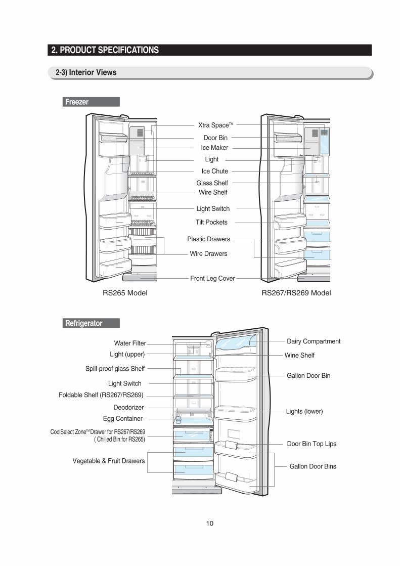
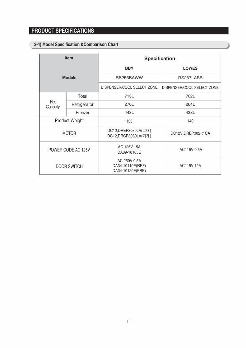


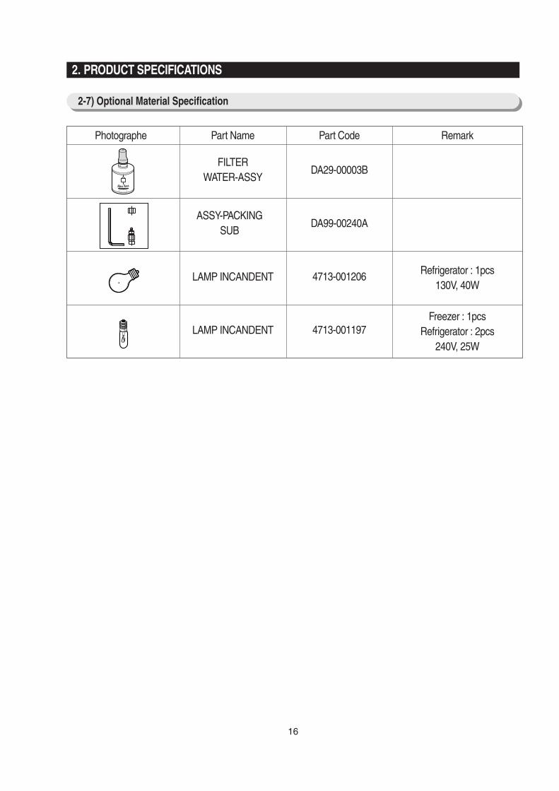
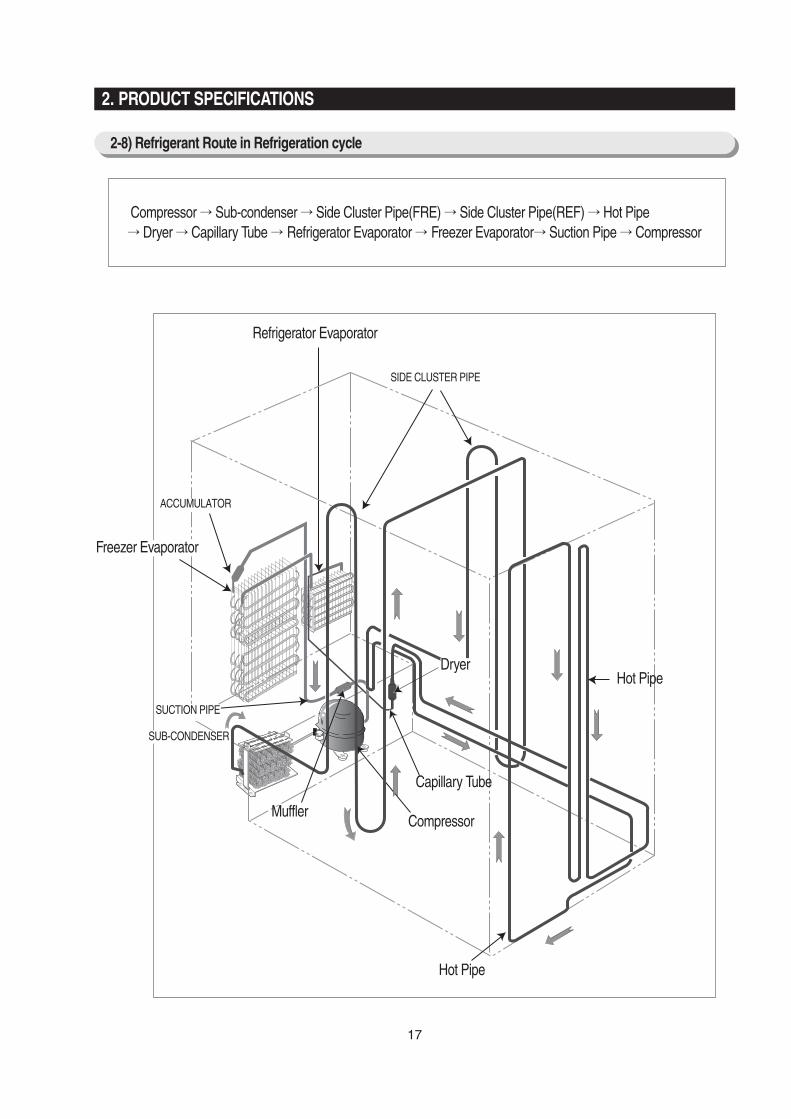
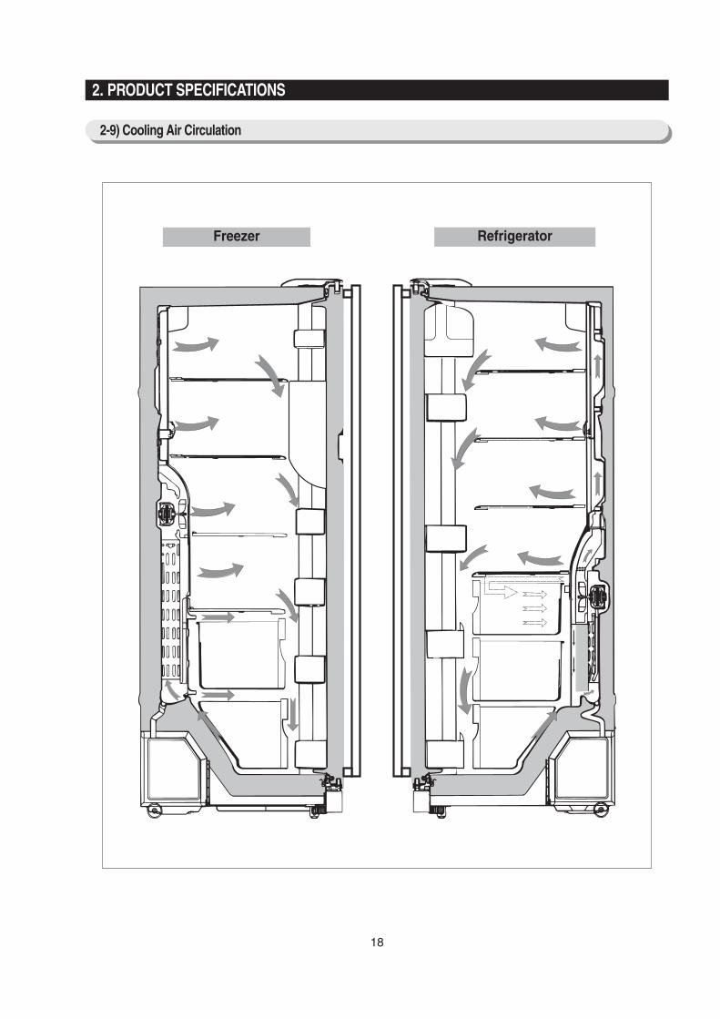


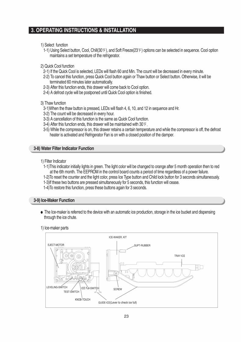


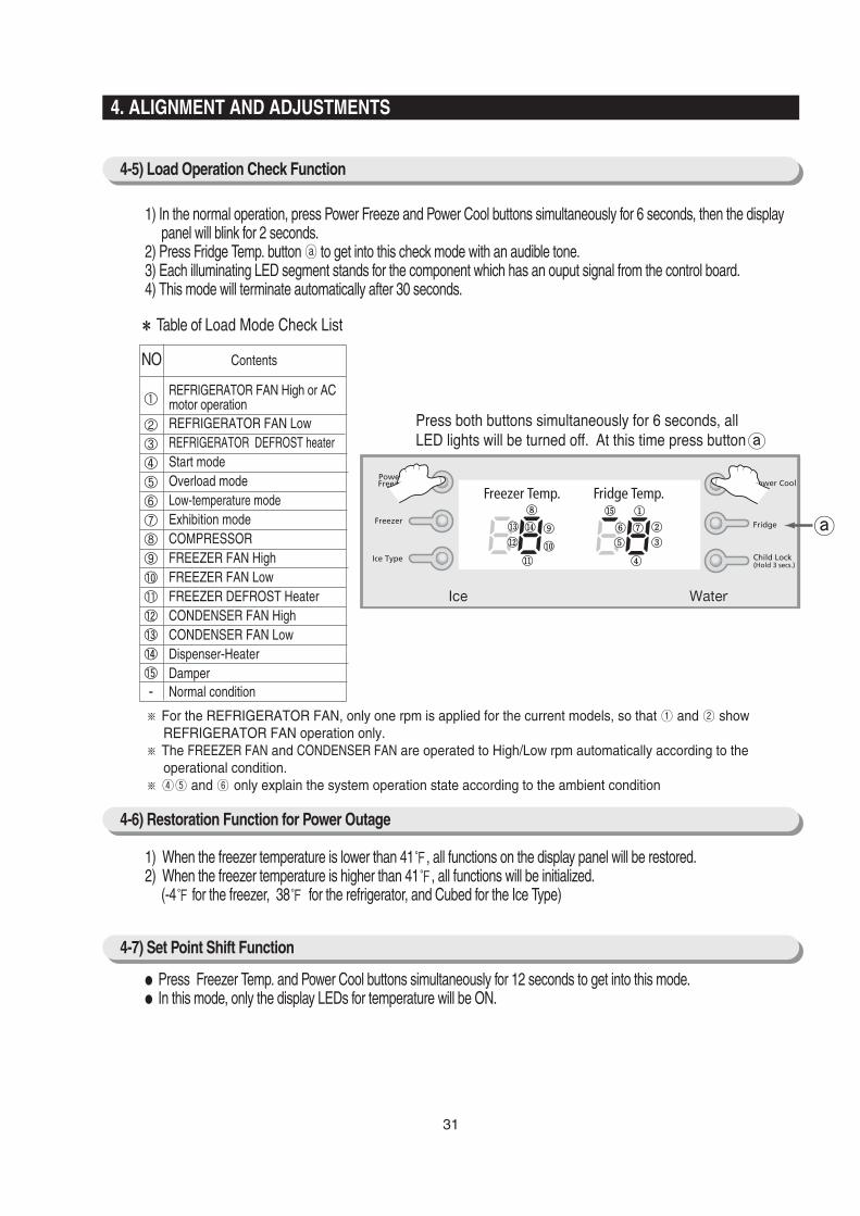

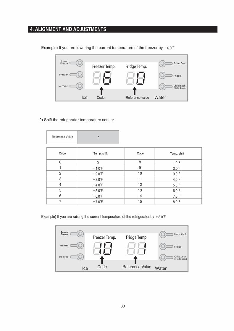
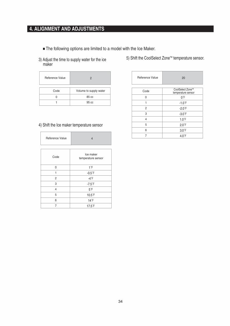

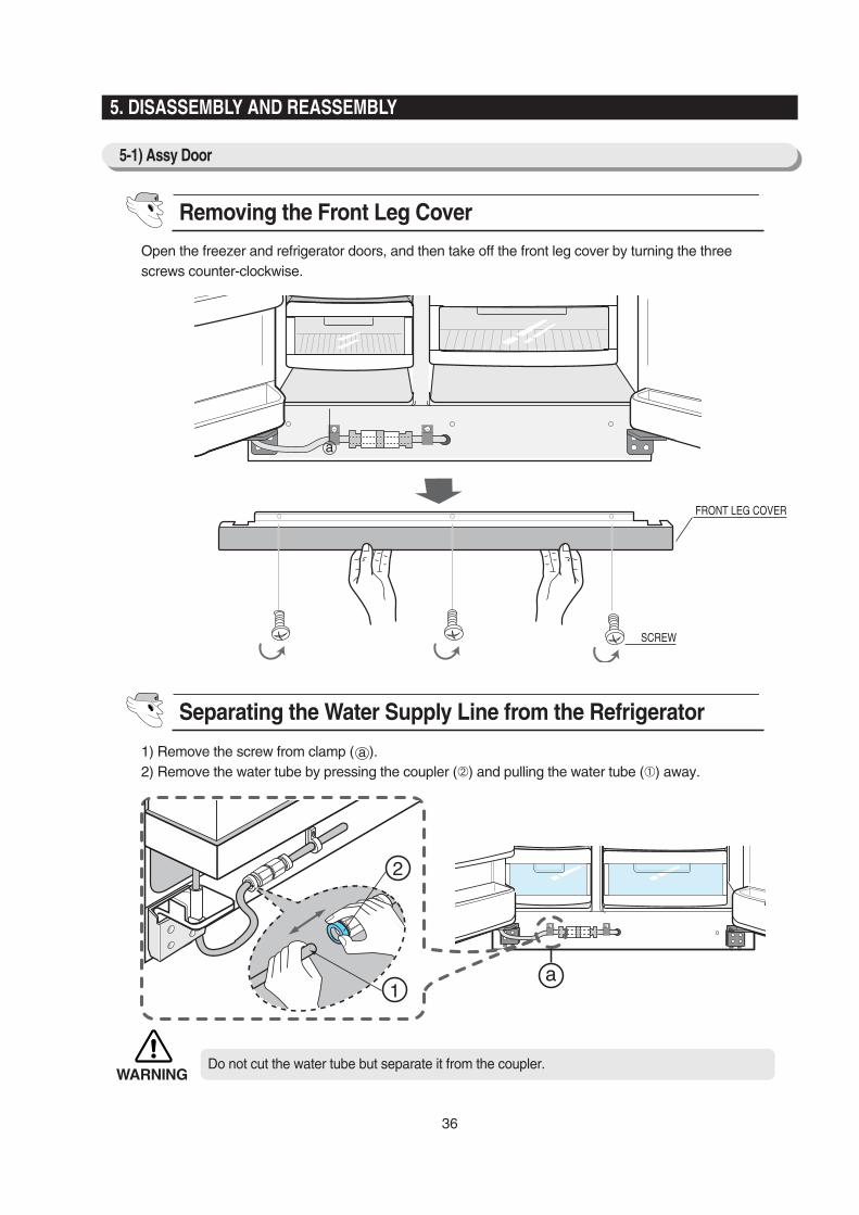

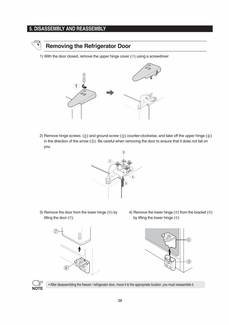

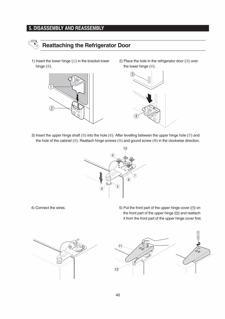

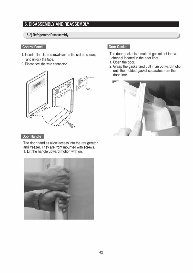

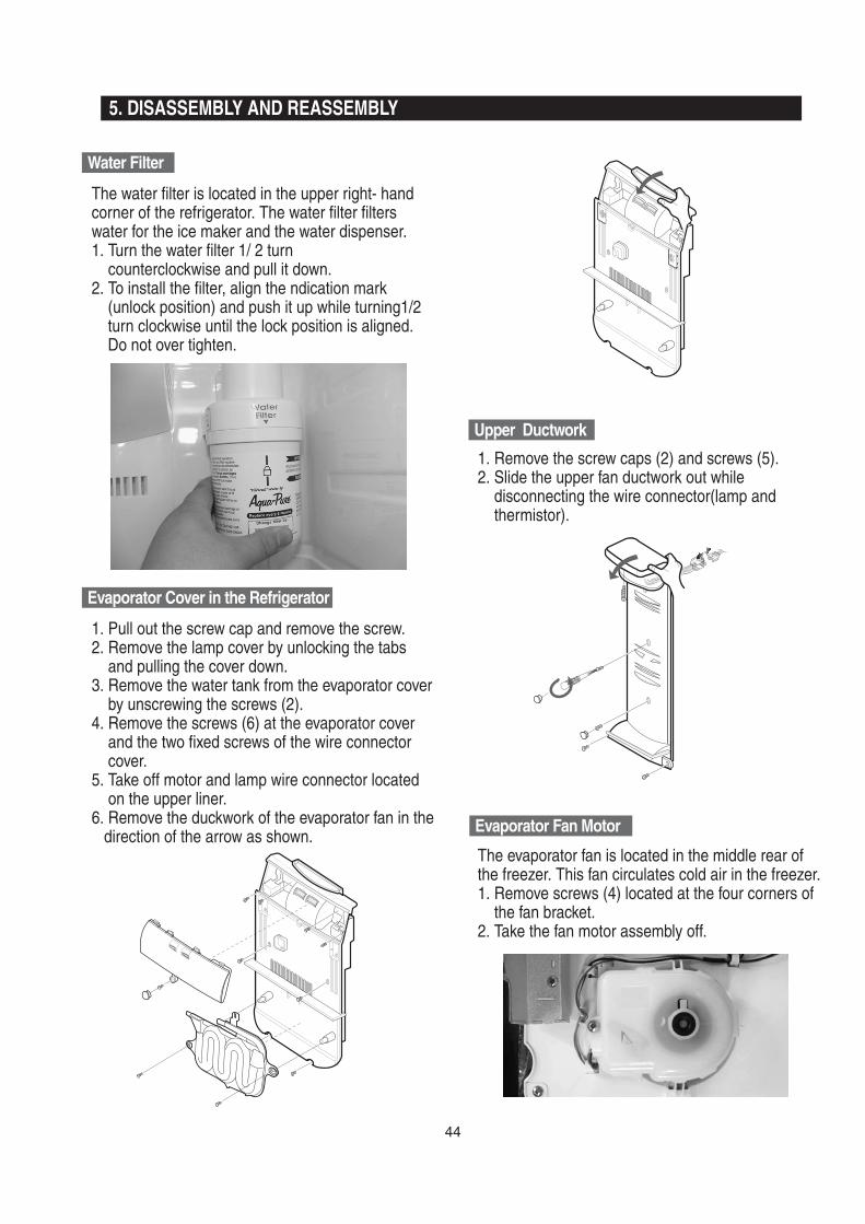


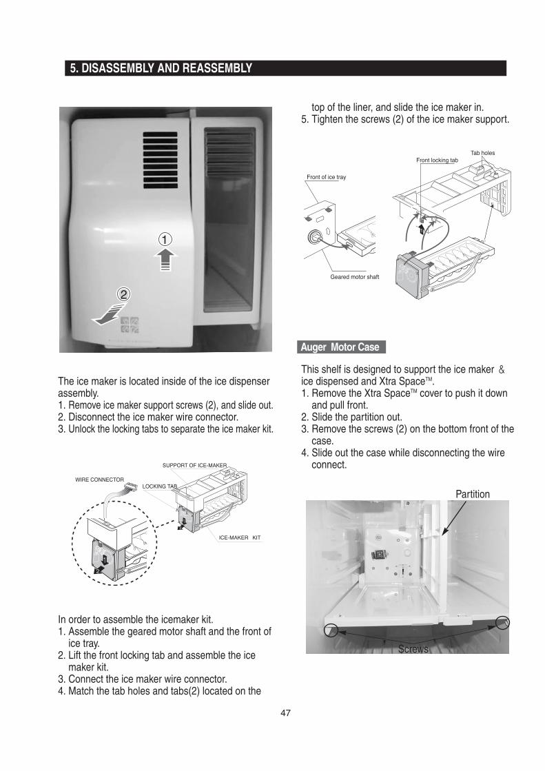

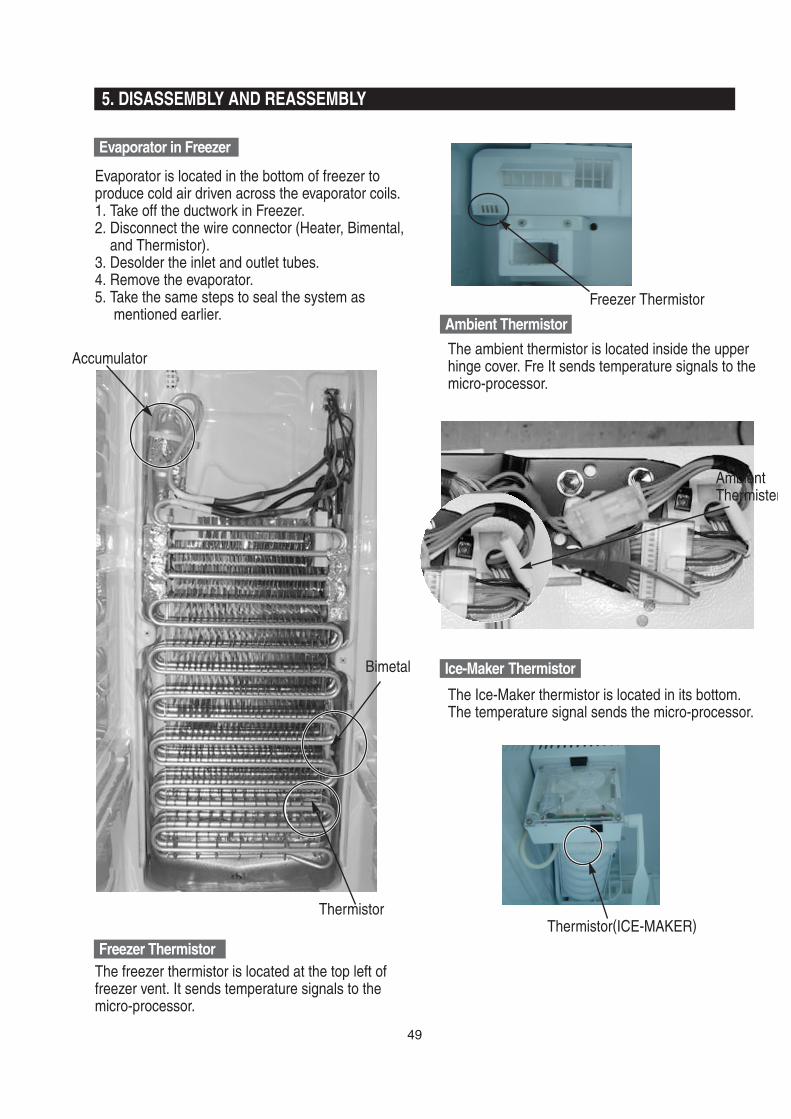
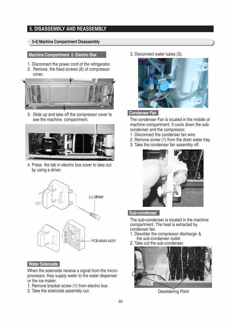

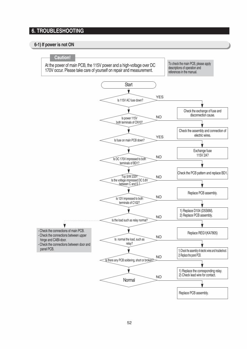
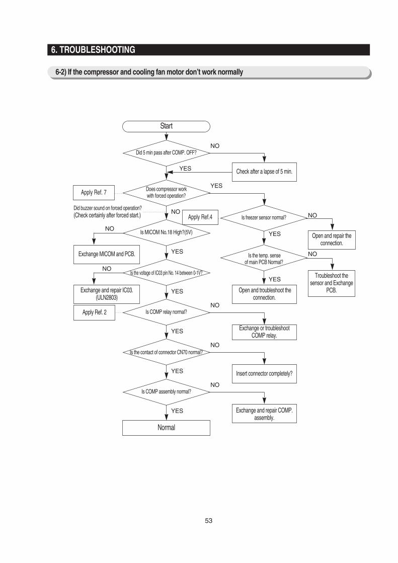


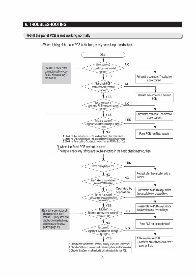


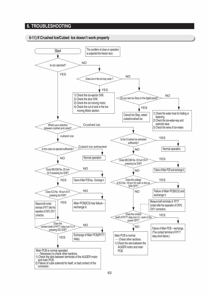

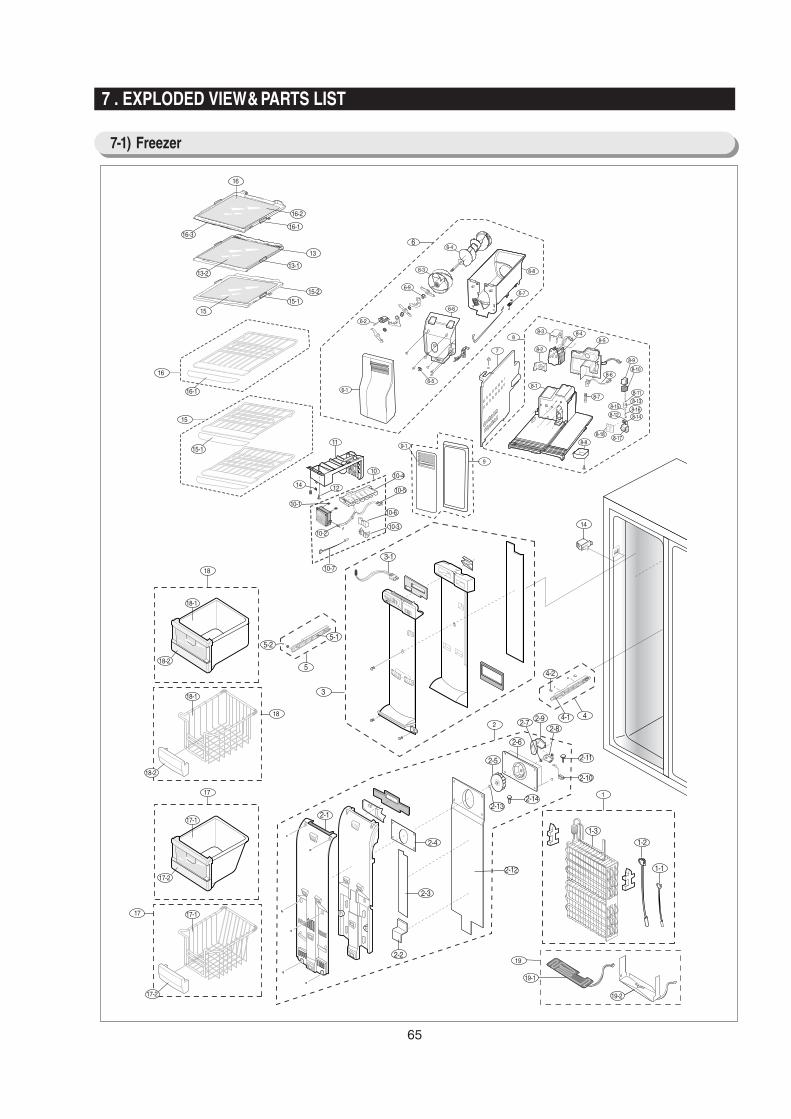

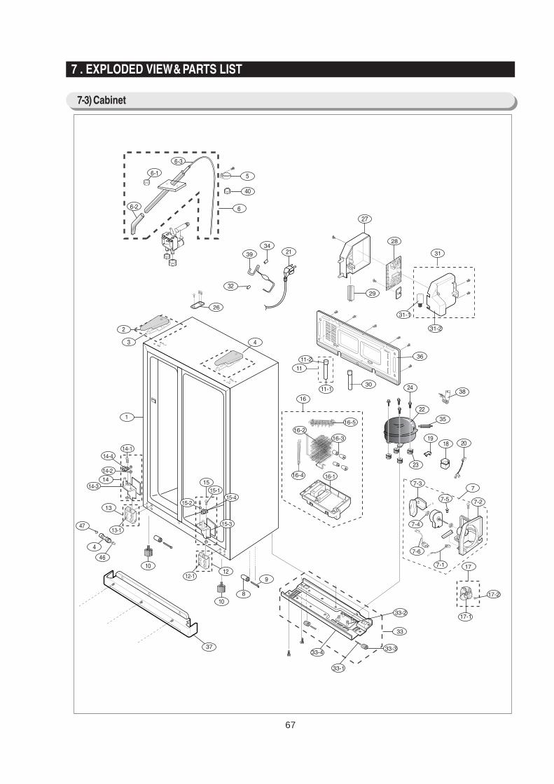
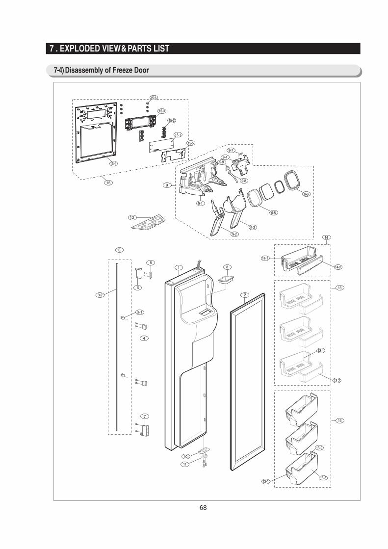
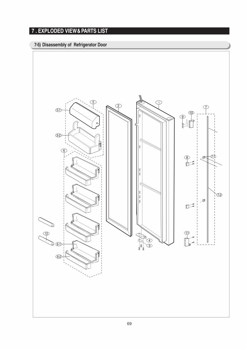

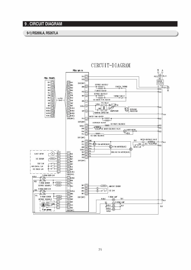

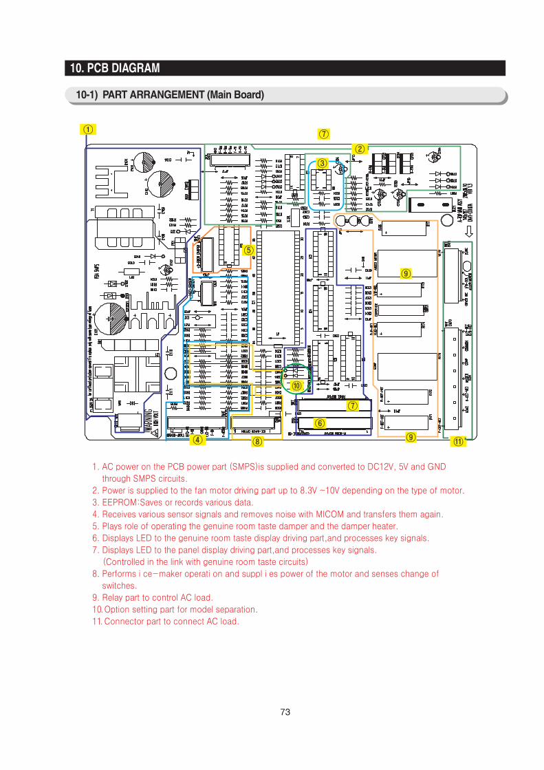


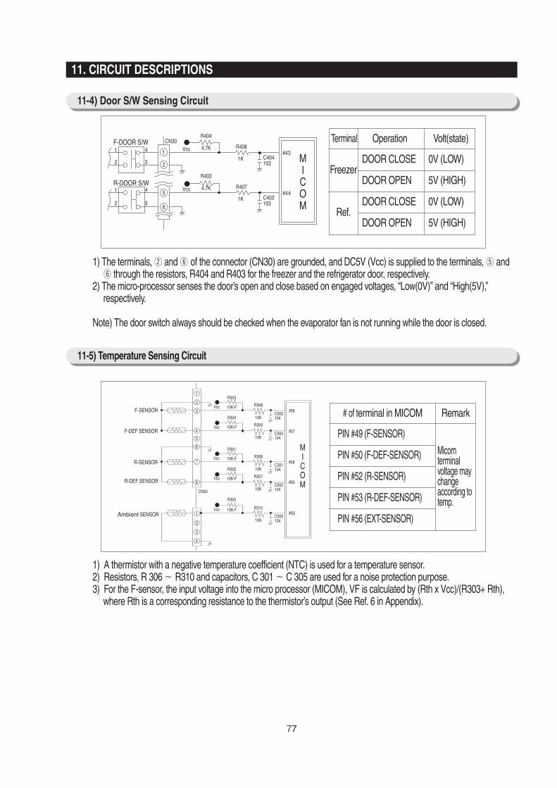
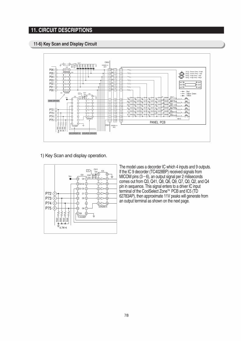

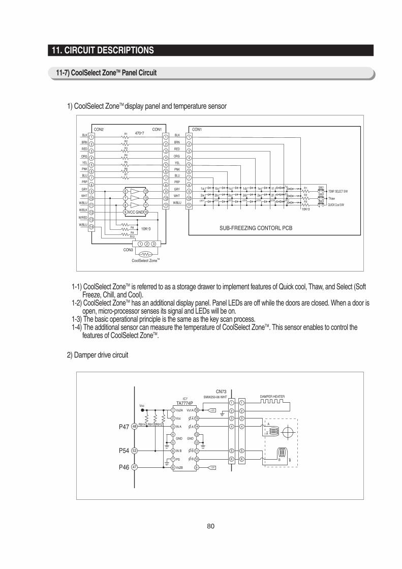

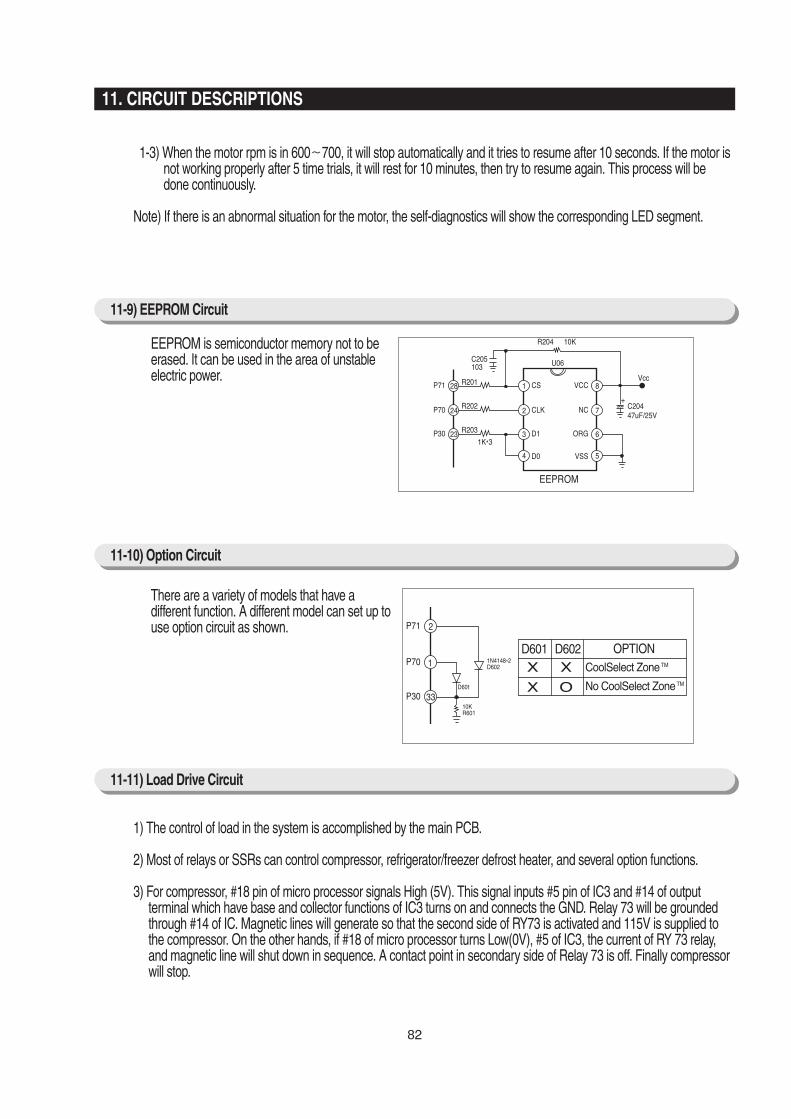


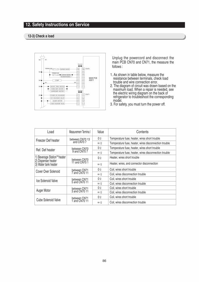
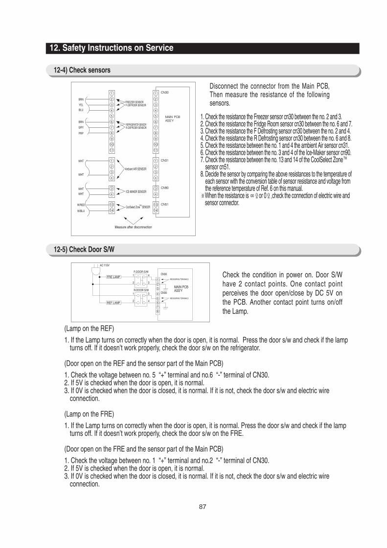

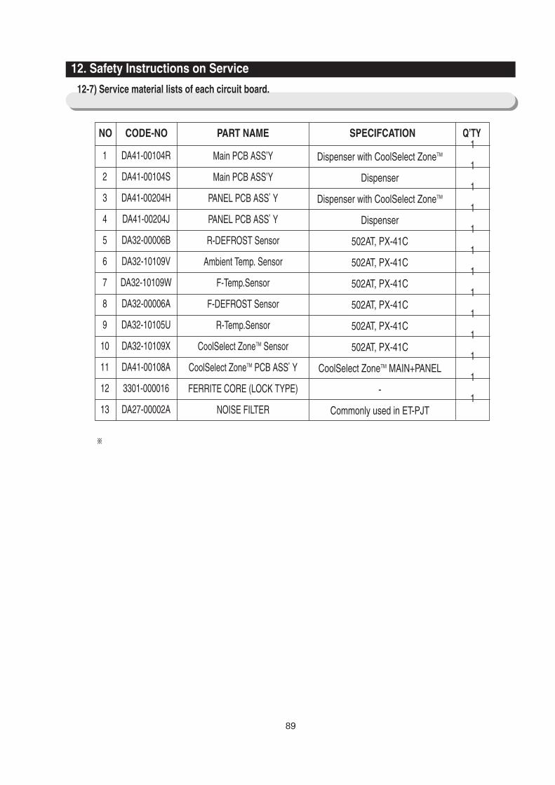

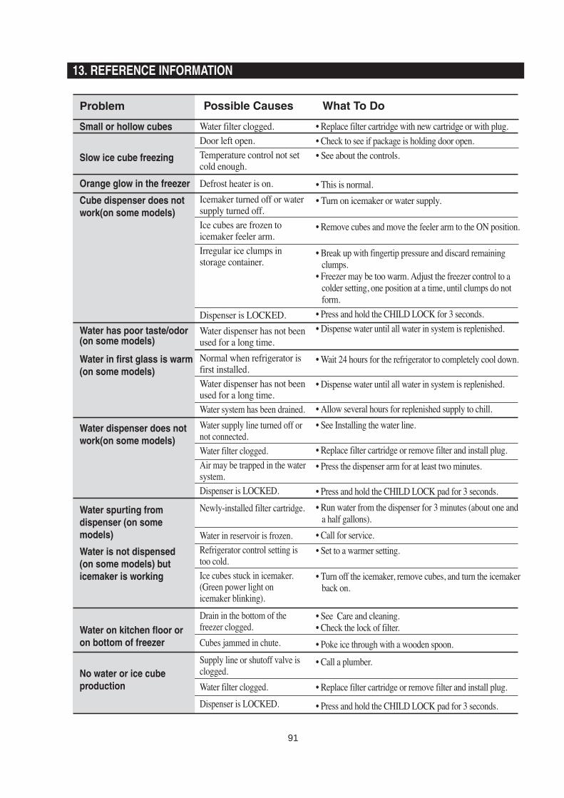


![A last updating evolution model for online social networks · Z.Buetal./PhysicaA392(2013)2240–2247 2241 richer’’phenomenon,inwhichdegreedistributionobeyspower-lawP(k)∼k−3[8,9].Thecompetitionaspectwassubse](https://static.documents.pub/doc/80x56/604db746c987ed17440a9b1d/a-last-updating-evolution-model-for-online-social-networks-zbuetalphysicaa39220132240a2247.jpg)
