70
Voice Evacuation Part Number 151267B, 03/02 SILENT KNIGHT SKE-SERIES Installation and Operation Manual

VoiceEvacuation
Part Number 151267B, 03/02
SILENT KNIGHT
SKE-SERIES
Installation andOperation Manual
151267 i
Content
Section 1Overview ...................................................................................................................................................... 1-1
1.1 Features .................................................................................................................................................... 1-11.2 Optional Accessories ................................................................................................................................ 1-21.3 About This Manual .................................................................................................................................. 1-21.4 How to Contact Silent Knight .................................................................................................................. 1-2
Section 2Agency Listings, Approvals, and Requirements ................................... 2-1
2.1 FCC Warning ........................................................................................................................................... 2-12.2 Underwriters Laboratories (UL) .............................................................................................................. 2-1
2.2.1 Requirements for All Installations .................................................................................................... 2-12.2.2 Requirements for Local Protected Fire Alarm Systems ................................................................... 2-1
Section 3Installation ................................................................................................................................................. 3-1
3.1 Environmental Specifications .................................................................................................................. 3-13.2 Electrical Specification ............................................................................................................................ 3-13.3 Board Layout ............................................................................................................................................ 3-2
3.3.1 Terminal Strip 1 ................................................................................................................................ 3-33.3.2 Terminal Strip 2 ................................................................................................................................ 3-33.3.3 System LEDs .................................................................................................................................... 3-43.3.4 Microphone Connection ................................................................................................................... 3-53.3.5 RS-232 Serial Connector .................................................................................................................. 3-53.3.6 Microphone (MIC) Gain ................................................................................................................... 3-53.3.7 S1 & S2 Message Test Buttons ......................................................................................................... 3-53.3.8 AC Delay Switch .............................................................................................................................. 3-5
3.4 Mounting the Control Panel ..................................................................................................................... 3-63.4.1 Wiring Specifications ....................................................................................................................... 3-6
3.5 Mounting the Main Control Board in the Cabinet ................................................................................... 3-83.6 Speaker Wiring ........................................................................................................................................ 3-9
3.6.1 Wiring Lengths ................................................................................................................................. 3-93.6.2 Class B (Style Y) ............................................................................................................................ 3-103.6.3 Class A (Style Z) ............................................................................................................................. 3-10
3.7 Input Circuits .......................................................................................................................................... 3-113.7.1 CMD1 Input Circuit ........................................................................................................................ 3-11
3.7.1.1 Class B (Style Y) .................................................................................................................. 3-113.7.1.2 Class A (Style Z) .................................................................................................................. 3-12
3.7.2 CMD2 Input Circuit ........................................................................................................................ 3-123.8 Connecting Power .................................................................................................................................. 3-13
3.8.1 AC Power ........................................................................................................................................ 3-133.8.2 Backup Battery Power .................................................................................................................... 3-15
SKE-Series Voice Evacuation System Installation/Operation Manual
ii 151267
Section 4Programming ......................................................................................................................................... 4-1
4.1 DIP Switch Programming ........................................................................................................................ 4-14.2 Recording Custom Message ..................................................................................................................... 4-3
4.2.1 Input Message 3 From the Microphone ............................................................................................ 4-44.2.1.1 Record Message 3 Using the Microphone ............................................................................. 4-44.2.1.2 To Erase Message 3 ............................................................................................................... 4-4
4.2.2 Input Message 3 From a PC .............................................................................................................. 4-44.2.2.1 Using the Aux Audio input .................................................................................................... 4-54.2.2.2 Using 7780 Software .............................................................................................................. 4-6
Section 5SKE-ZN4 Zone Splitter ............................................................................................................... 5-1
5.1 SKE-ZN4 Board and Components ........................................................................................................... 5-15.1.1 Terminal Strip 1 ................................................................................................................................ 5-25.1.2 Terminal Strip 2 ................................................................................................................................ 5-25.1.3 Terminal Strip 3 ................................................................................................................................ 5-25.1.4 Terminal Strip 4 ................................................................................................................................ 5-35.1.5 Terminal Strip 5 ................................................................................................................................ 5-35.1.6 Manual Zone Switches ...................................................................................................................... 5-35.1.7 All Call Switch .................................................................................................................................. 5-45.1.8 Zone Supervision Selectors .............................................................................................................. 5-45.1.9 LED Descriptions ............................................................................................................................. 5-4
5.2 SKE-ZN4 Electrical Specifications ......................................................................................................... 5-45.3 Mounting the SKE-ZN4 In the SKE-450 Cabinet ................................................................................... 5-55.4 Speaker Wiring ........................................................................................................................................ 5-7
5.4.1 Wiring Procedure .............................................................................................................................. 5-75.4.2 Class B (Style Y) .............................................................................................................................. 5-75.4.3 Class A (Style Z) ............................................................................................................................... 5-85.4.4 FACP Alarm Control Wiring ............................................................................................................ 5-9
Section 6SKE-SRM ..................................................................................................................................................... 6-1
6.1 Specifications ........................................................................................................................................... 6-16.2 LED Description ...................................................................................................................................... 6-26.3 Installation Instruction ............................................................................................................................. 6-2
6.3.1 Mounting the SKE-SRM Cabinet. .................................................................................................... 6-26.3.2 Wiring Instructions ........................................................................................................................... 6-46.3.3 Remote Microphone Operation ........................................................................................................ 6-5

Content
151267 iii
Section 7SKE-V70 Module Installation ............................................................................................ 7-1
7.1 Mounting .................................................................................................................................................. 7-17.2 Speaker Wiring ........................................................................................................................................ 7-3
7.2.1 Connecting the SKE-V70 to the Main Control Panel ....................................................................... 7-37.2.2 Connecting the SKE-V70 to the SKE-ZN4 or -ZN6 ........................................................................ 7-37.2.3 Class B (Style Y) .............................................................................................................................. 7-57.2.4 Class A (Style Z) ............................................................................................................................... 7-5
Section 8SKE-ZN6 Six Zone Splitter Installation ................................................................ 1-1
8.1 SKE-ZN6 Board and Components ........................................................................................................... 1-18.1.1 Terminal Strip 1 ................................................................................................................................ 1-28.1.2 Terminal Strip 2 ................................................................................................................................ 1-38.1.3 Terminal Strip 3 ................................................................................................................................ 1-48.1.4 Manual Zone Switches ...................................................................................................................... 1-48.1.5 All Call Switch .................................................................................................................................. 1-48.1.6 LED Descriptions ............................................................................................................................. 1-4
8.2 SKE-ZN6 Electrical Specifications ......................................................................................................... 1-58.3 Mounting the SKE-ZN6 In the SKE-450 Cabinet ................................................................................... 1-58.4 Speaker Wiring ........................................................................................................................................ 1-7
8.4.1 Wiring Procedure .............................................................................................................................. 1-78.4.2 Class B (Style Y) .............................................................................................................................. 1-78.4.3 Class A (Style Z) ............................................................................................................................... 1-98.4.4 FACP Alarm Control Wiring .......................................................................................................... 1-10
Section 9Battery Calculation ......................................................................................................................... 9-1
9.1 Calculating Current Draw and Standby Battery ...................................................................................... 9-1The Current Draw Calculations, Table 9-1 (Section 9.1.1) .......................................................... 9-1
9.1.1 Current Draw Table .......................................................................................................................... 9-2
Silent Knight Fire Product Warranty and Return Policy
General Terms and ConditionsRepair and RA ProcedureAdvanced Replacement PolicyLimited Warranty

SKE-Series Voice Evacuation System Installation/Operation Manual
iv 151267
151267 1-1
Section 1Overview
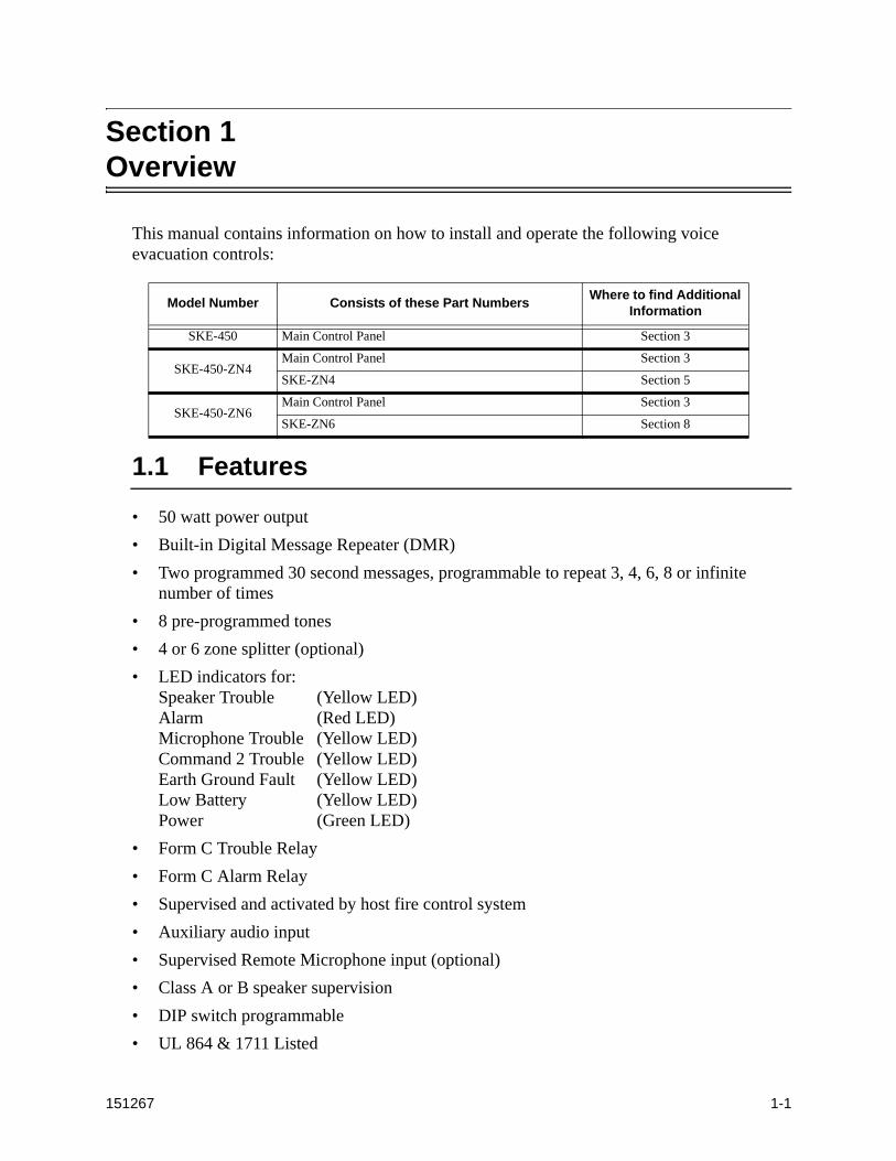
This manual contains information on how to install and operate the following voice evacuation controls:
1.1 Features
• 50 watt power output
• Built-in Digital Message Repeater (DMR)
• Two programmed 30 second messages, programmable to repeat 3, 4, 6, 8 or infinite number of times
• 8 pre-programmed tones
• 4 or 6 zone splitter (optional)
• LED indicators for:Speaker Trouble (Yellow LED)Alarm (Red LED)Microphone Trouble (Yellow LED)Command 2 Trouble (Yellow LED)Earth Ground Fault (Yellow LED)Low Battery (Yellow LED)Power (Green LED)
• Form C Trouble Relay
• Form C Alarm Relay
• Supervised and activated by host fire control system
• Auxiliary audio input
• Supervised Remote Microphone input (optional)
• Class A or B speaker supervision
• DIP switch programmable
• UL 864 & 1711 Listed
Model Number Consists of these Part NumbersWhere to find Additional
Information
SKE-450 Main Control Panel Section 3
SKE-450-ZN4Main Control Panel Section 3
SKE-ZN4 Section 5
SKE-450-ZN6Main Control Panel Section 3
SKE-ZN6 Section 8
SKE-Series Voice Evacuation System Installation/Operation Manual
1-2 151267
1.2 Optional Accessories
Part Number Description
SKE-ZN4 4 Zone Audio Splitter (see Section 5 for more information)
SKE-SRM Supervised Remote Microphone (see Section 6 for details)
SKE-ZN6 6 Zone Audio Splitter (see Section 8 for more information)
SKE-V70 Converts the speaker circuit voltage from 25 to 70.7 Vrms(see Section 7 for more information)
1.3 About This Manual
This manual is intended to be a complete reference for all installation and operation tasks. Please let us know if the manual does not meet your needs in any way. We value your feedback!
1.4 How to Contact Silent Knight
If you have a question or encounter a problem not covered in this manual, contact Silent Knight Technical Support at 800--328-0103 (or 763-493-6455). To order parts, contact Silent
Knight Sales at 800-446-6444 (or 763-493-6435).
151267 2-1
Section 2Agency Listings, Approvals, and Requirements
2.1 FCC Warning
This device has been verified to comply with FCC Rules Part 15. Operation is subject to the two following conditions: (1) This device may not cause radio interference, and (2) this device must accept any interference received, including interference that may cause undesired operation.
2.2 Underwriters Laboratories (UL)
The SKE-450 is UL listed as a voice evacuation unit for use in NFPA 72 systems. If the SKE-450 and its accessories are to be used as part of a UL installation, carefully read the UL requirements in this section. For more information on NFPA 72 standards, refer to the NFPA National Fire Alarm Code.
2.2.1 Requirements for All InstallationsGeneral requirements are described in this section. When installing an individual device, refer to the specific section of the manual for additional requirements.
1. All field wiring must be installed in accordance with NFPA 70, National Electric Code.
2. Use UL listed notification devices with the SKE-450 voice evacuation system.
3. A full system checkout must be performed any time the panel is programmed.
4. UL installations using Class B wiring for the speaker circuit require the use of a Model 7630 EOL resistor assembly.
2.2.2 Requirements for Local Protected Fire Alarm Systems
At least one UL-listed, supervised notification appliance must be used.

SKE-Series Voice Evacuation System Installation/Operation Manual
2-2 151267

151267 3-1
Section 3Installation
This section of the manual is intended to help you plan your tasks to facilitate the installation. Please read this section thoroughly, especially if you are installing a SKE-450 control for the first time.
3.1 Environmental Specifications
It is important to protect the SKE-450 control panel from moisture. To prevent damage, the following conditions should be avoided when installing the units:
• Do not mount directly on exterior walls, especially masonry walls (condensation)
• Do not mount directly on exterior walls below grade (condensation)
• Protect from plumbing leaks
• Protect from splash caused by sprinkler inspection ports
• Do not mount in areas with humidity-generating equipment (such as dryers, production machinery)
When selecting a location to mount the panel, it should be mounted where it will NOT be exposed to temperatures outside the range of 0°C-49°C (32°F-120°F) or humidity outside the range of 10%-85% at 30°C (86°F) noncondensing.
3.2 Electrical Specification
* Specify voltage requirements when ordering.
Note: Refer to the control panel wiring diagram to determine which power source is required for your control.
Table 3-1: Electrical Specifications
Circuit Rating
Operating Voltage 120 Vrms @ 60 Hz @ 1.2 amp*230 Vrms @ 50Hz @ .607 amp
Trouble & Alarm Relays 2.5 A @ 30 VDC resistive

SKE-Series Voice Evacuation System Installation/Operation Manual
3-2 151267
3.3 Board Layout
This section of the manual describes the components of the control panel that may be used by the installer or operator.
Figure 3-1 Board Layout
ProgrammingDIPs
MessageTest Buttons
Expansion Connector
BatteryConnector
MicrophoneGain
RS-232Connector
System LEDs
AC Transformer
OutputRelays
ControlSignalsAC Delay
Switch
AlarmActivation
Inputs
Speaker CircuitConnections
Terminal Strip 1
Terminal Strip 2
Connector
SKE-SRMRemote MicrophoneTerminals
MicrophoneConnector

Installation
151267 3-3
3.3.1 Terminal Strip 1
3.3.2 Terminal Strip 2
Table 3-2: Terminal Strip 1 Description
Terminal Name Comments
+ Remote Microphone
See Section 6.3.2 for details.
-
Active
IN
Neg Aux Audio (Input)
For recording custom message only. See Section 4.2.2.
In
Enable
FO Not Used
Com Alarm (Relay)
Form C alarm relay
NC
NO
Com Trouble (Relay)
Form C trouble relay
NC
NO
Table 3-3: Terminal Strip 2 Description
Terminal Name Comments
+ CMD2 IN
A short across this input will activate message 2.
–
+ CMD1 IN
A reverse polarity trip from the FACP will activate message 1.
–
+ CMD1 OUT–
+ SPK IN Used for Class A (Style Z) speaker connections
–
+ SPK OUT
Used for Class B (Style Y) and Class A (Style Z) speaker connections.–

SKE-Series Voice Evacuation System Installation/Operation Manual
3-4 151267
3.3.3 System LEDsThe control panel has LEDs which indicate system operation, alarms, and trouble conditions. Table 3-4 lists the LEDs and their function. See also Figure 3-2.
Figure 3-2 System LEDs Close-up View
Table 3-4: LED Descriptions
LED Name Color Description
Speaker Trouble Yellow ON = Speaker circuit troubleOFF = Speaker/amp is operating normally
Alarm Red ON = AlarmOFF = No alarms
Mic Trouble Yellow ON = Trouble with on-board microphoneOFF = Microphone connectedFlashing = Trouble with remote microphone
CMD2 Trouble Yellow ON = Trouble condition with CMD2 input, EOL troubleOFF = CMD2 operating properly
Earth Ground Yellow ON = Earth Ground Fault detectedOFF = No Earth Ground Fault detected
Battery Status Yellow ON = Low BatteryOFF = Battery OK
Power Green ON (Steady) = Power is presentFlashing = No AC power to the control.
Speaker Trouble
Alarm
Mic Trouble
CMD2 Trouble
Earth Ground Trouble
Power
Battery Status
Installation
151267 3-5
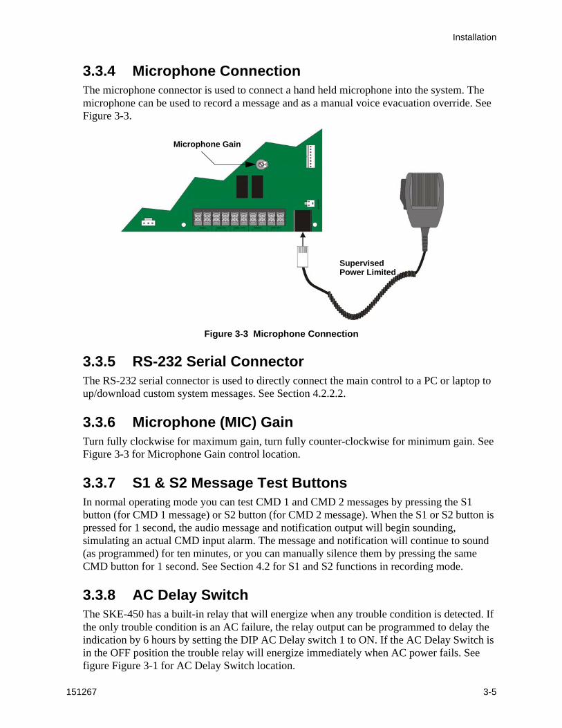
3.3.4 Microphone ConnectionThe microphone connector is used to connect a hand held microphone into the system. The microphone can be used to record a message and as a manual voice evacuation override. See Figure 3-3.
Figure 3-3 Microphone Connection
3.3.5 RS-232 Serial ConnectorThe RS-232 serial connector is used to directly connect the main control to a PC or laptop to up/download custom system messages. See Section 4.2.2.2.
3.3.6 Microphone (MIC) GainTurn fully clockwise for maximum gain, turn fully counter-clockwise for minimum gain. See Figure 3-3 for Microphone Gain control location.
3.3.7 S1 & S2 Message Test ButtonsIn normal operating mode you can test CMD 1 and CMD 2 messages by pressing the S1 button (for CMD 1 message) or S2 button (for CMD 2 message). When the S1 or S2 button is pressed for 1 second, the audio message and notification output will begin sounding, simulating an actual CMD input alarm. The message and notification will continue to sound (as programmed) for ten minutes, or you can manually silence them by pressing the same CMD button for 1 second. See Section 4.2 for S1 and S2 functions in recording mode.
3.3.8 AC Delay SwitchThe SKE-450 has a built-in relay that will energize when any trouble condition is detected. If the only trouble condition is an AC failure, the relay output can be programmed to delay the indication by 6 hours by setting the DIP AC Delay switch 1 to ON. If the AC Delay Switch is in the OFF position the trouble relay will energize immediately when AC power fails. See figure Figure 3-1 for AC Delay Switch location.
SupervisedPower Limited
Microphone Gain
SKE-Series Voice Evacuation System Installation/Operation Manual
3-6 151267
3.4 Mounting the Control Panel
Read the environmental specifications in Section 3.1 before mounting the control panel cabinet. This will ensure that you select a suitable mounting location.
The panel should be accessible to main drop wiring runs. It should be mounted as close to the center of the building as possible and located within a secured area, but should be accessible for testing and service.
Mount the control panel cabinet so it is firmly secured to the wall surface. When mounting on concrete, especially when moisture is expected, attach a piece of 3/4-inch plywood to the concrete surface and then attach the cabinet to the plywood. Also mount any other modules to the plywood.
The cabinet can be surface or flush-mounted. If you will be flush-mounting the cabinet, the hole for the enclosure should be 14.5" W x 24.75" H x 3-7/16" D (36.8cm W x 62.9cm H x 8.73cm D). Do not flush-mount in a wall designated as a fire break.
3.4.1 Wiring SpecificationsThe maximum line resistance of the wire run from FACP to voice evacuation control system is 50Ω. All wiring and devices installed in the system must meet the standards described in National Electrical Code (NFPA 70), NFPA Standard 72, and Life Safety Code (NFPA 101).
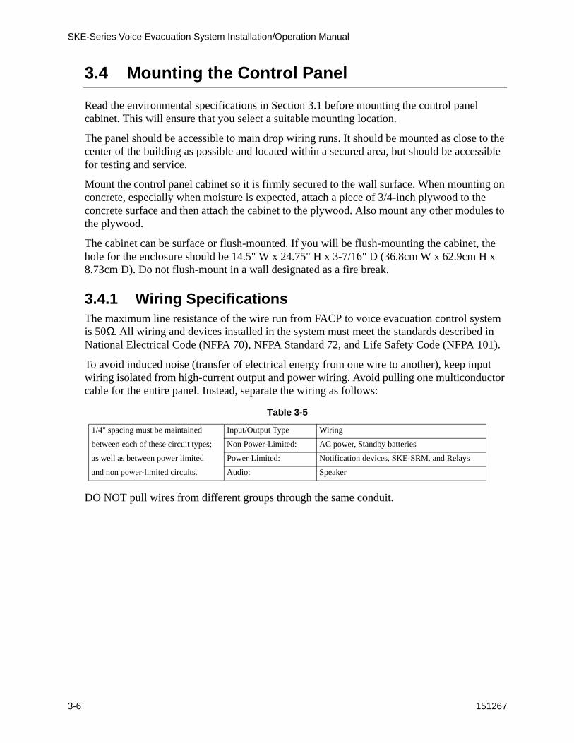
To avoid induced noise (transfer of electrical energy from one wire to another), keep input wiring isolated from high-current output and power wiring. Avoid pulling one multiconductor cable for the entire panel. Instead, separate the wiring as follows:
DO NOT pull wires from different groups through the same conduit.
Table 3-5
1/4" spacing must be maintained Input/Output Type Wiring
between each of these circuit types; Non Power-Limited: AC power, Standby batteries
as well as between power limited Power-Limited: Notification devices, SKE-SRM, and Relays
and non power-limited circuits. Audio: Speaker
Installation
151267 3-7
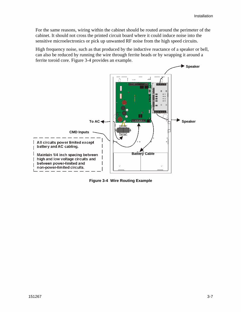
For the same reasons, wiring within the cabinet should be routed around the perimeter of the cabinet. It should not cross the printed circuit board where it could induce noise into the sensitive microelectronics or pick up unwanted RF noise from the high speed circuits.
High frequency noise, such as that produced by the inductive reactance of a speaker or bell, can also be reduced by running the wire through ferrite beads or by wrapping it around a ferrite toroid core. Figure 3-4 provides an example.
Figure 3-4 Wire Routing Example
Speaker
SpeakerTo AC
CMD Inputs
Battery Cable
SKE-Series Voice Evacuation System Installation/Operation Manual
3-8 151267
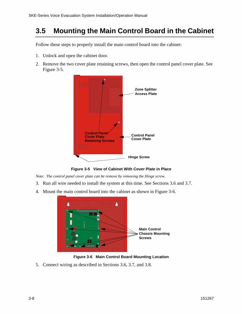
3.5 Mounting the Main Control Board in the Cabinet
Follow these steps to properly install the main control board into the cabinet:
1. Unlock and open the cabinet door.
2. Remove the two cover plate retaining screws, then open the control panel cover plate. See Figure 3-5.
Figure 3-5 View of Cabinet With Cover Plate in Place
Note: The control panel cover plate can be remove by removing the Hinge screw.
3. Run all wire needed to install the system at this time. See Sections 3.6 and 3.7.
4. Mount the main control board into the cabinet as shown in Figure 3-6.
Figure 3-6 Main Control Board Mounting Location
5. Connect wiring as described in Sections 3.6, 3.7, and 3.8.
Control PanelCover Plate Control Panel
Cover Plate
Zone SplitterAccess Plate
Retaining Screws
Hinge Screw
Main Control Chassis Mounting Screws
Installation
151267 3-9
3.6 Speaker Wiring
Each SKE-450 supplies one NAC (Notification Appliance Circuit) for speaker connection. The speaker circuit can be supervised and wired Class B (Style Y) or Class A (Style Z). The speaker circuit is capable of 50 watts of power at 25 Vrms or 70.7 Vrms (using the SKE-V70 Module, see Section 7 for SKE-V70 installing instructions).
Note: If the SKE-V70 Module is installed, all speaker wiring must be separated by a minimum of 1/4” from the low voltage wiring, and must exit the cabinet through its own opening.
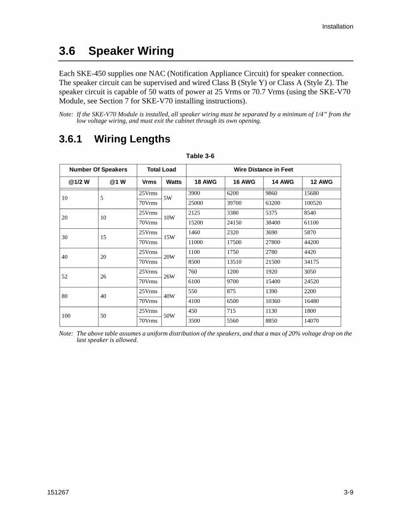
3.6.1 Wiring Lengths
Note: The above table assumes a uniform distribution of the speakers, and that a max of 20% voltage drop on the last speaker is allowed.
Table 3-6
Number Of Speakers Total Load Wire Distance in Feet
@1/2 W @1 W Vrms Watts 18 AWG 16 AWG 14 AWG 12 AWG
10 525Vrms
5W3900 6200 9860 15680
70Vrms 25000 39700 63200 100520
20 1025Vrms
10W2125 3380 5375 8540
70Vrms 15200 24150 38400 61100
30 1525Vrms
15W1460 2320 3690 5870
70Vrms 11000 17500 27800 44200
40 2025Vrms
20W1100 1750 2780 4420
70Vrms 8500 13510 21500 34175
52 2625Vrms
26W760 1200 1920 3050
70Vrms 6100 9700 15400 24520
80 4025Vrms
40W550 875 1390 2200
70Vrms 4100 6500 10360 16480
100 5025Vrms
50W450 715 1130 1800
70Vrms 3500 5560 8850 14070
SKE-Series Voice Evacuation System Installation/Operation Manual
3-10 151267
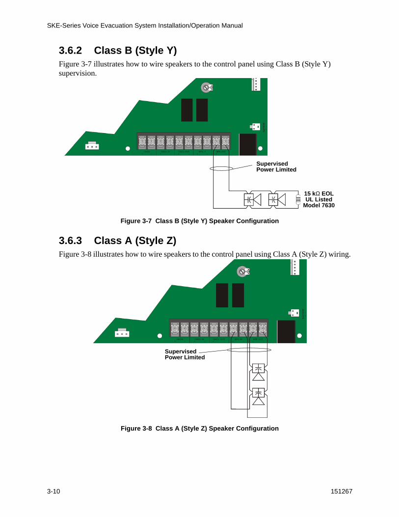
3.6.2 Class B (Style Y)Figure 3-7 illustrates how to wire speakers to the control panel using Class B (Style Y) supervision.
Figure 3-7 Class B (Style Y) Speaker Configuration
3.6.3 Class A (Style Z)Figure 3-8 illustrates how to wire speakers to the control panel using Class A (Style Z) wiring.
Figure 3-8 Class A (Style Z) Speaker Configuration
SupervisedPower Limited
15 kΩ EOLUL Listed
Model 7630
SupervisedPower Limited
Installation
151267 3-11
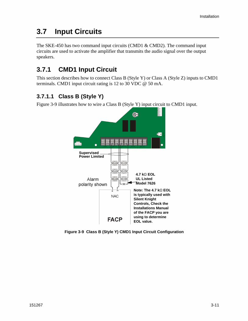
3.7 Input Circuits
The SKE-450 has two command input circuits (CMD1 & CMD2). The command input circuits are used to activate the amplifier that transmits the audio signal over the output speakers.
3.7.1 CMD1 Input CircuitThis section describes how to connect Class B (Style Y) or Class A (Style Z) inputs to CMD1 terminals. CMD1 input circuit rating is 12 to 30 VDC @ 50 mA.
3.7.1.1 Class B (Style Y)Figure 3-9 illustrates how to wire a Class B (Style Y) input circuit to CMD1 input.
Figure 3-9 Class B (Style Y) CMD1 Input Circuit Configuration
SupervisedPower Limited
4.7 kΩ EOLUL ListedModel 7626
Note: The 4.7 kΩ EOL is typically used with Silent Knight Controls, Check the Installations Manual of the FACP you are using to determine EOL value.
SKE-Series Voice Evacuation System Installation/Operation Manual
3-12 151267
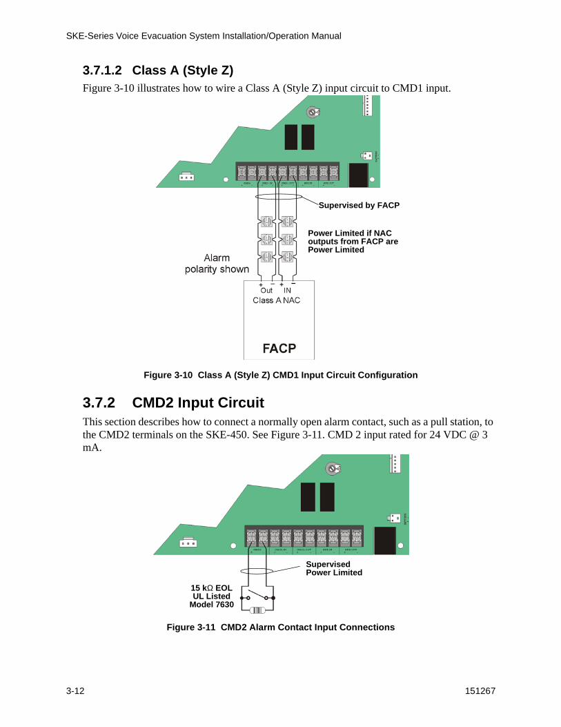
3.7.1.2 Class A (Style Z)Figure 3-10 illustrates how to wire a Class A (Style Z) input circuit to CMD1 input.
Figure 3-10 Class A (Style Z) CMD1 Input Circuit Configuration
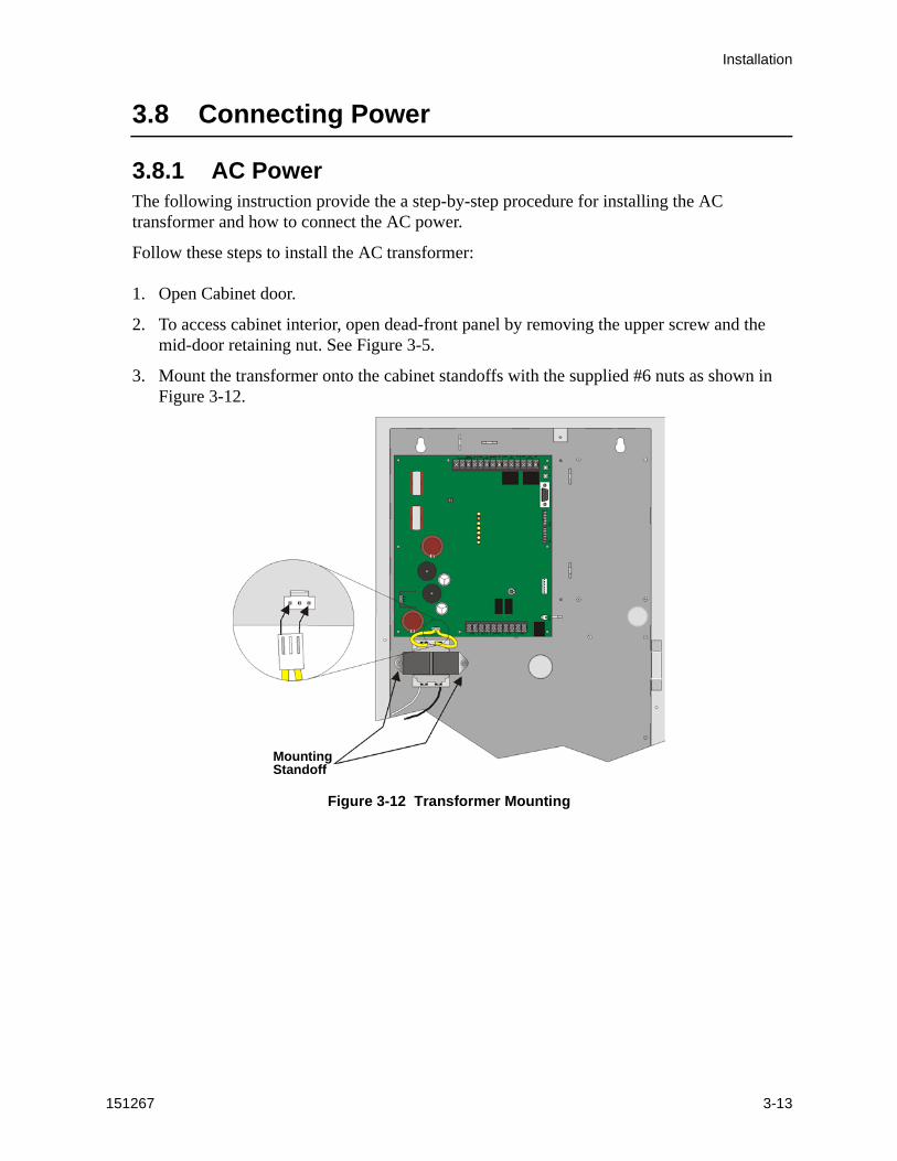
3.7.2 CMD2 Input CircuitThis section describes how to connect a normally open alarm contact, such as a pull station, to the CMD2 terminals on the SKE-450. See Figure 3-11. CMD 2 input rated for 24 VDC @ 3 mA.
Figure 3-11 CMD2 Alarm Contact Input Connections
Supervised by FACP
Power Limited if NACoutputs from FACP arePower Limited
SupervisedPower Limited
15 kΩ EOLUL Listed
Model 7630
Installation
151267 3-13
3.8 Connecting Power
3.8.1 AC PowerThe following instruction provide the a step-by-step procedure for installing the AC transformer and how to connect the AC power.
Follow these steps to install the AC transformer:
1. Open Cabinet door.
2. To access cabinet interior, open dead-front panel by removing the upper screw and the mid-door retaining nut. See Figure 3-5.
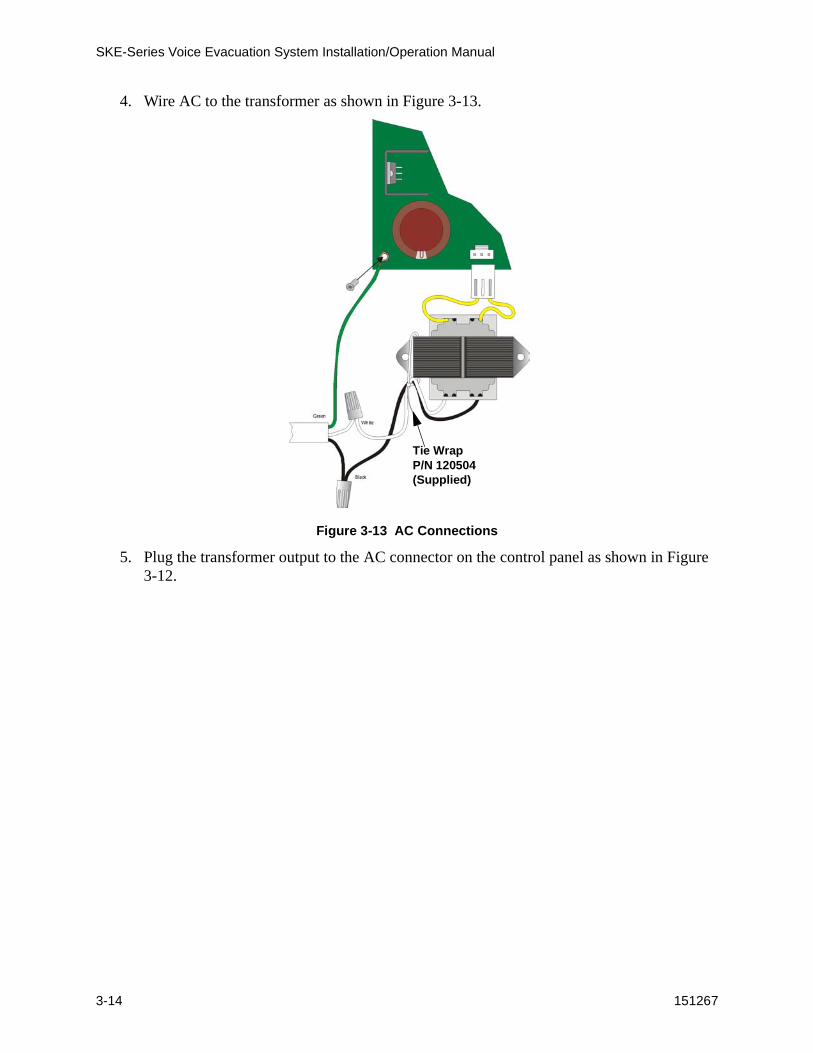
3. Mount the transformer onto the cabinet standoffs with the supplied #6 nuts as shown in Figure 3-12.
Figure 3-12 Transformer Mounting
MountingStandoff
SKE-Series Voice Evacuation System Installation/Operation Manual
3-14 151267
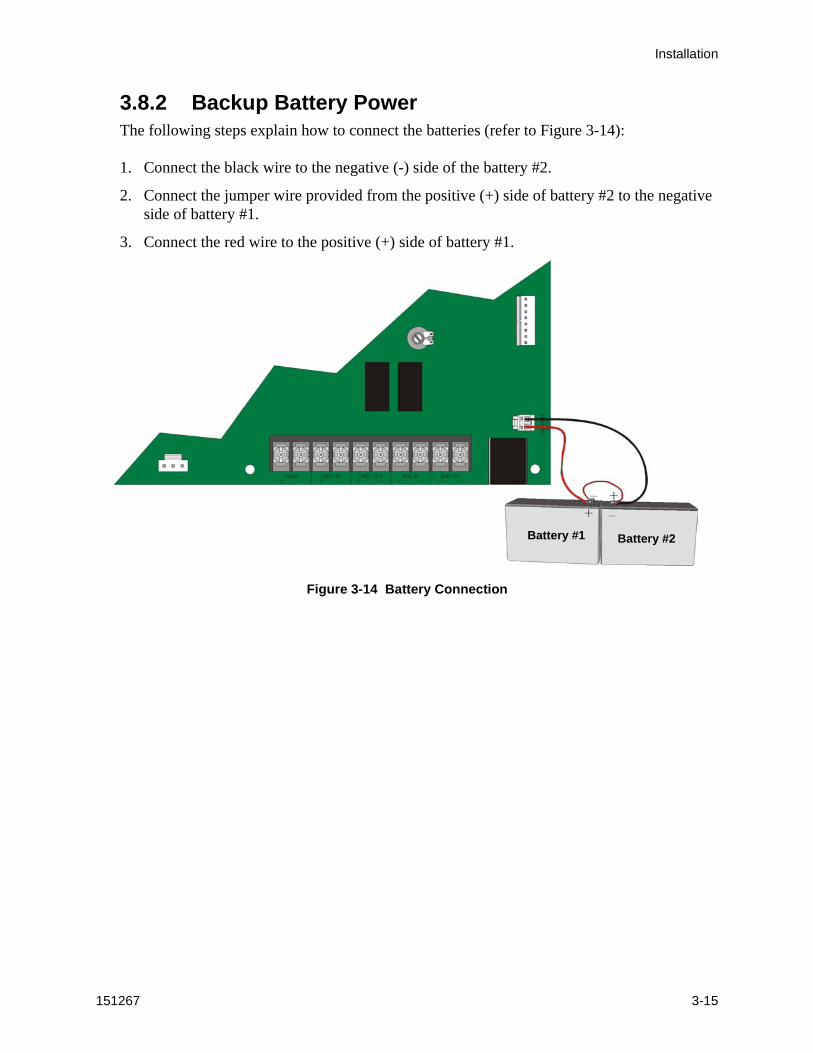
4. Wire AC to the transformer as shown in Figure 3-13.
Figure 3-13 AC Connections
5. Plug the transformer output to the AC connector on the control panel as shown in Figure 3-12.
Tie Wrap P/N 120504 (Supplied)
Installation
151267 3-15
3.8.2 Backup Battery PowerThe following steps explain how to connect the batteries (refer to Figure 3-14):
1. Connect the black wire to the negative (-) side of the battery #2.
2. Connect the jumper wire provided from the positive (+) side of battery #2 to the negative side of battery #1.
3. Connect the red wire to the positive (+) side of battery #1.
Figure 3-14 Battery Connection
Battery #2Battery #1

SKE-Series Voice Evacuation System Installation/Operation Manual
3-16 151267
151267 4-1
Section 4Programming
This section of the manual describes how to program the SKE-450 using the programming DIP switches.
4.1 DIP Switch Programming
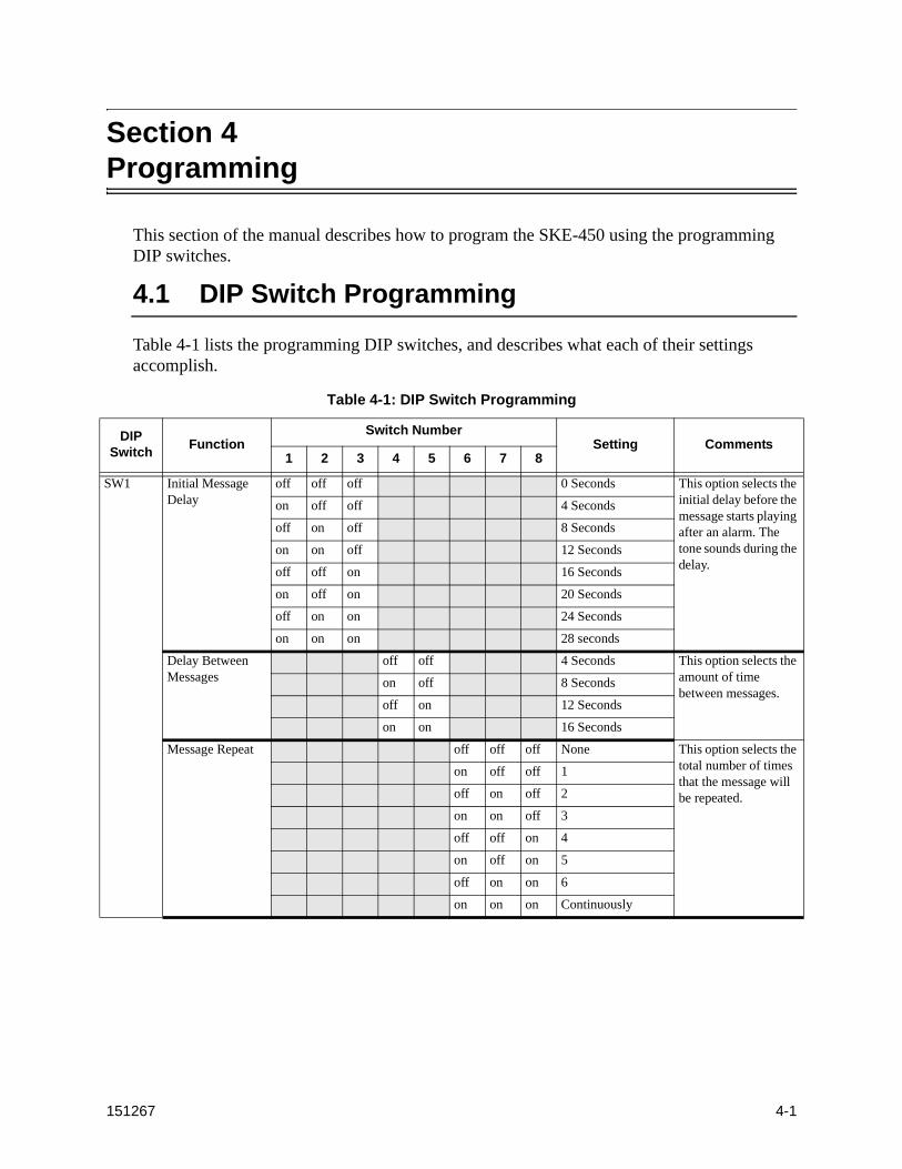
Table 4-1 lists the programming DIP switches, and describes what each of their settings accomplish.
Table 4-1: DIP Switch Programming
DIP Switch
FunctionSwitch Number
Setting Comments1 2 3 4 5 6 7 8
SW1 Initial Message Delay
off off off 0 Seconds This option selects the initial delay before the message starts playing after an alarm. The tone sounds during the delay.
on off off 4 Seconds
off on off 8 Seconds
on on off 12 Seconds
off off on 16 Seconds
on off on 20 Seconds
off on on 24 Seconds
on on on 28 seconds
Delay Between Messages
off off 4 Seconds This option selects the amount of time between messages.
on off 8 Seconds
off on 12 Seconds
on on 16 Seconds
Message Repeat off off off None This option selects the total number of times that the message will be repeated.
on off off 1
off on off 2
on on off 3
off off on 4
on off on 5
off on on 6
on on on Continuously
SKE-SeriesVoice Evacuation System Installation/Operation Manual
4-2 151267
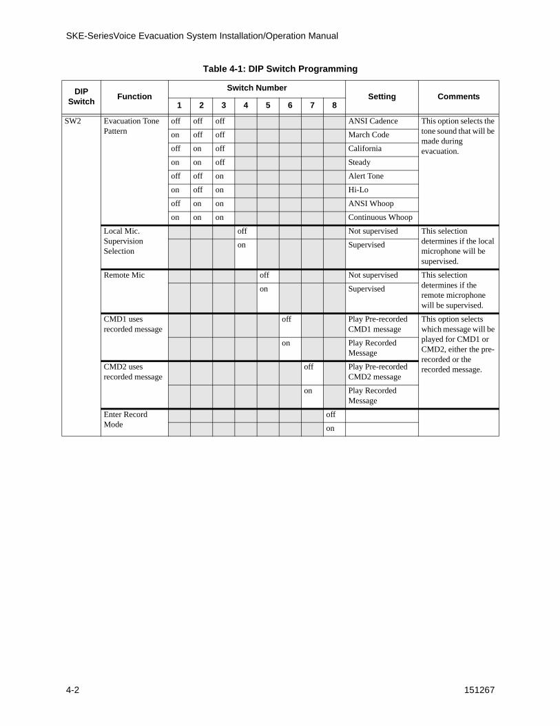
SW2 Evacuation Tone Pattern
off off off ANSI Cadence This option selects the tone sound that will be made during evacuation.
on off off March Code
off on off California
on on off Steady
off off on Alert Tone
on off on Hi-Lo
off on on ANSI Whoop
on on on Continuous Whoop
Local Mic. Supervision Selection
off Not supervised This selection determines if the local microphone will be supervised.
on Supervised
Remote Mic off Not supervised This selection determines if the remote microphone will be supervised.
on Supervised
CMD1 uses recorded message
off Play Pre-recorded CMD1 message
This option selects which message will be played for CMD1 or CMD2, either the pre-recorded or the recorded message.
on Play Recorded Message
CMD2 uses recorded message
off Play Pre-recorded CMD2 message
on Play Recorded Message
Enter Record Mode
off
on
Table 4-1: DIP Switch Programming
DIP Switch
FunctionSwitch Number
Setting Comments1 2 3 4 5 6 7 8
Programming
151267 4-3
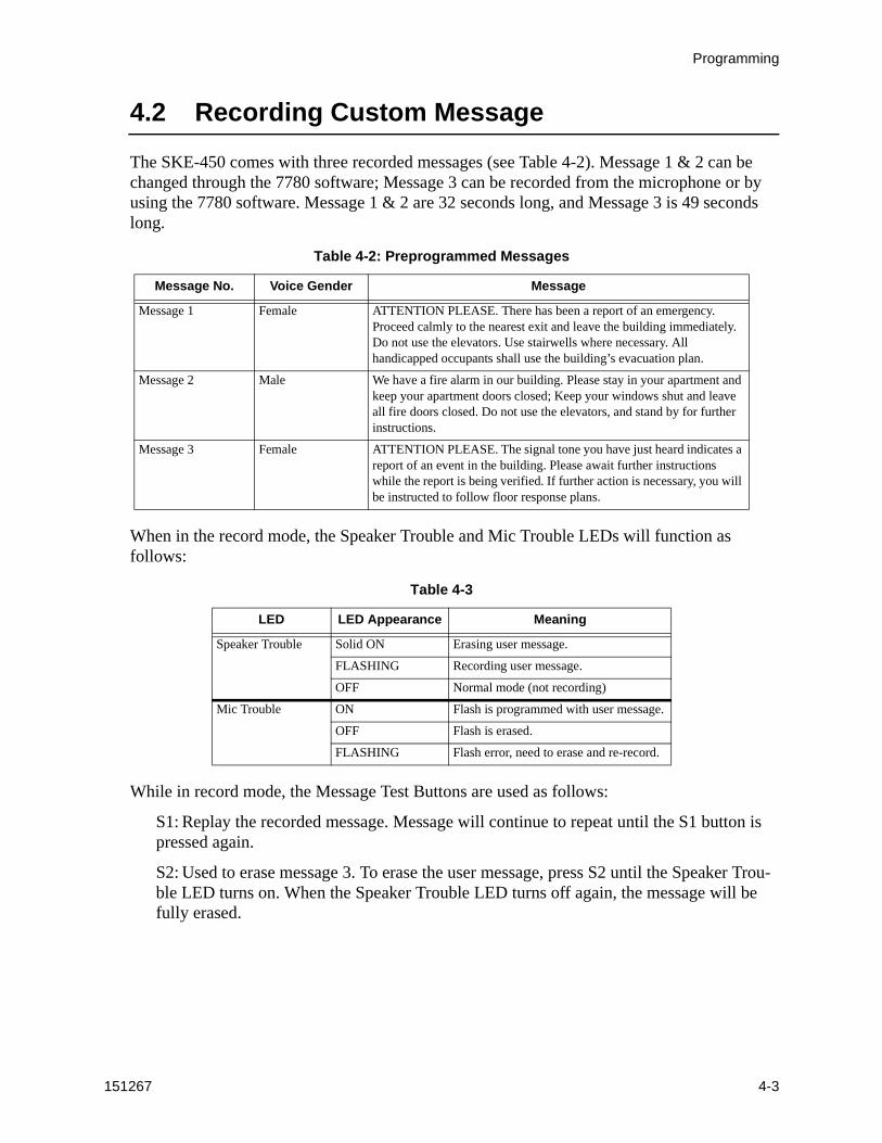
4.2 Recording Custom Message
The SKE-450 comes with three recorded messages (see Table 4-2). Message 1 & 2 can be changed through the 7780 software; Message 3 can be recorded from the microphone or by using the 7780 software. Message 1 & 2 are 32 seconds long, and Message 3 is 49 seconds long.
When in the record mode, the Speaker Trouble and Mic Trouble LEDs will function as follows:
While in record mode, the Message Test Buttons are used as follows:
S1: Replay the recorded message. Message will continue to repeat until the S1 button is pressed again.
S2: Used to erase message 3. To erase the user message, press S2 until the Speaker Trou-ble LED turns on. When the Speaker Trouble LED turns off again, the message will be fully erased.
Table 4-2: Preprogrammed Messages
Message No. Voice Gender Message
Message 1 Female ATTENTION PLEASE. There has been a report of an emergency. Proceed calmly to the nearest exit and leave the building immediately. Do not use the elevators. Use stairwells where necessary. All handicapped occupants shall use the building’s evacuation plan.
Message 2 Male We have a fire alarm in our building. Please stay in your apartment and keep your apartment doors closed; Keep your windows shut and leave all fire doors closed. Do not use the elevators, and stand by for further instructions.
Message 3 Female ATTENTION PLEASE. The signal tone you have just heard indicates a report of an event in the building. Please await further instructions while the report is being verified. If further action is necessary, you will be instructed to follow floor response plans.
Table 4-3
LED LED Appearance Meaning
Speaker Trouble Solid ON Erasing user message.
FLASHING Recording user message.
OFF Normal mode (not recording)
Mic Trouble ON Flash is programmed with user message.
OFF Flash is erased.
FLASHING Flash error, need to erase and re-record.
SKE-SeriesVoice Evacuation System Installation/Operation Manual
4-4 151267
4.2.1 Input Message 3 From the MicrophoneThis section contains information on how to record and erase message 3 from the control panel.
4.2.1.1 Record Message 3 Using the MicrophoneFollow these steps to record message 3 using the microphone:
1. Place DIP switch number 8 of SW2 to the “On” position.
The trouble relay will energize.
2. Press in the microphone switch and speak the desired message (49 seconds maximum).
While your message is being recorded, the Speaker Trouble LED will flash. Once the microphone switch is released, the Mic Trouble LED will Light.
If there is an error in the flash memory while recording, the Mic Trouble LED will flash. Then erase the message, and record message again.
Note: Once a message is recorded, a new message can not be recorded over it until the previous message is erased.
3. When you have completed recording message 3, return DIP switch number 8 of SW2 to the “Off” position.
4.2.1.2 To Erase Message 3Follow these steps to erase message 3:
1. Place DIP switch number 8 of SW2 to the “On” position.
The trouble relay will energize.
2. Press and hold Message Test Button S2 until the Speaker Trouble LED lights.
3. If you wish to record a new message, follow the steps listed in Section 4.2.1.1.
OR
4. Return DIP switch number 8 of SW2 to the “Off” position.
4.2.2 Input Message 3 From a PCThere are two ways to input message 3 into the system using a PC or laptop computer. Message 3 can be recorded from the audio output of a PC sound card, or through the serial port using the 7780 software.
Important! When the SKE-450 is in Record Mode, the trouble relay will energize and CMD1 relay will be open. Alarms will not be detected while the system is in Record Mode.

Programming
151267 4-5
4.2.2.1 Using the Aux Audio inputMessage 3 can be recorded from the “Line Out” on the sound card of a PC or Laptop.
To input a message through the Aux Audio terminals on the SKE-450:
1. Wire a speaker cable with 1/8” mini plug (Radio Shack Cat. No. 42-2454) to Aux Audio Neg and IN terminals. Refer to Figure 4-1.
Figure 4-1 Aux Audio Connection for Recording
2. Plug a the mini plug into the Line Out/Headphone jack on a PC or Laptop. See Figure 4-1.
3. Wire a switch between Aux Audio Enable and NEG. See Figure 4-1.
4. Place DIP switch number 8 of SW2 to the “On” position.
The trouble relay will energize.
5. Close the switch connected between Enable and NEG.
6. From the PC, play the desired audio file (such as a wave file). Maximum length of audio file is 49 seconds.
7. When audio file is complete, open the switch between Enable and NEG.
8. Remove the mini plug assembly from the control board.
9. Return DIP switch number 8 of SW2 to the “Off” position.
SKE-SeriesVoice Evacuation System Installation/Operation Manual
4-6 151267
4.2.2.2 Using 7780 SoftwareThe 7780 software is a software support utility that is used to download recorded messages (in .ske format stored on your PC hard drive) to the various message locations of the SKE-450. Messages can be uploaded from the SKE-450, stored, and used again in similar installations. The 7780 software can also be used to move messages to different message locations. For example, move message 1 to message 3 memory location.
To read/write .SKE formatted messages to and from the SKE-450 main panel, follow these steps:
1. Make sure that panel is in Normal mode. This is accomplished by setting DIP switch num-ber 8 on SW 2 to the “Off” position, and recycling power.
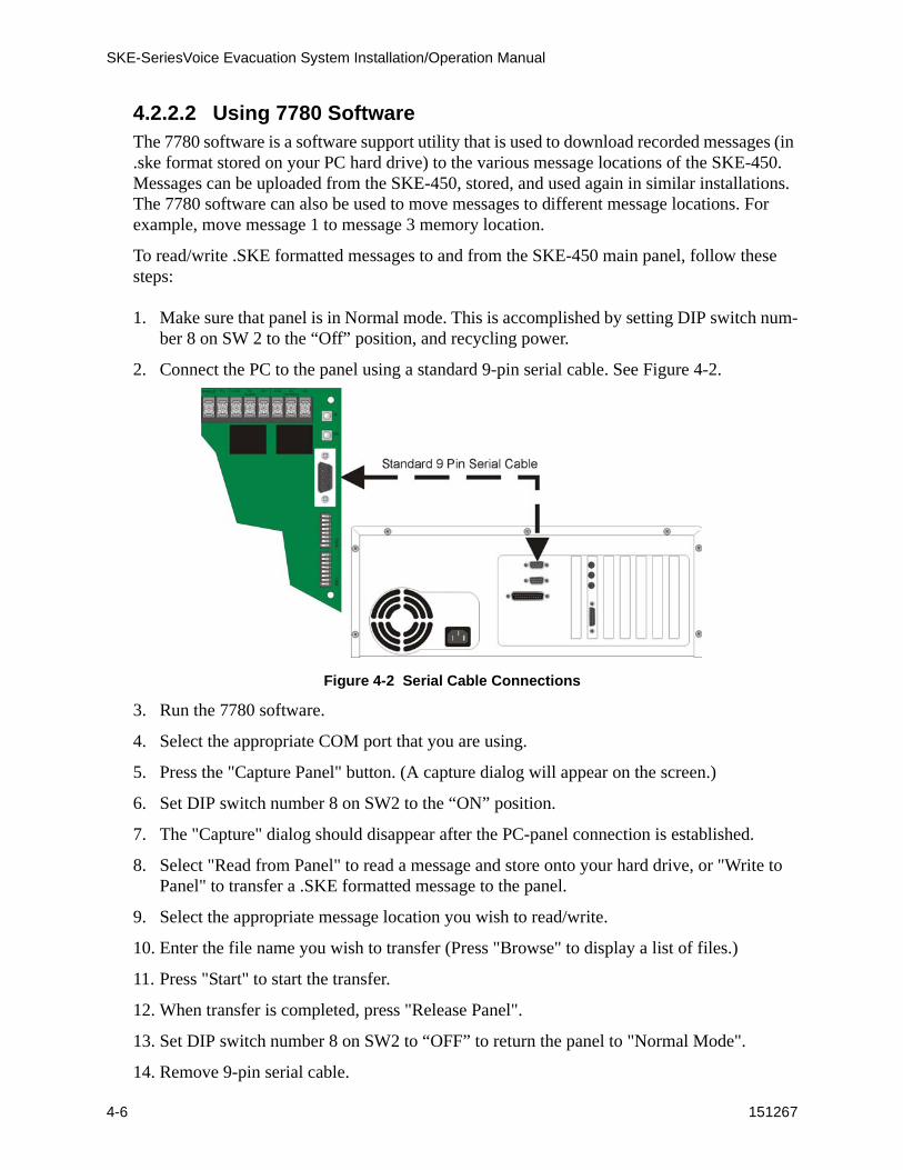
2. Connect the PC to the panel using a standard 9-pin serial cable. See Figure 4-2.
Figure 4-2 Serial Cable Connections
3. Run the 7780 software.
4. Select the appropriate COM port that you are using.
5. Press the "Capture Panel" button. (A capture dialog will appear on the screen.)
6. Set DIP switch number 8 on SW2 to the “ON” position.
7. The "Capture" dialog should disappear after the PC-panel connection is established.
8. Select "Read from Panel" to read a message and store onto your hard drive, or "Write to Panel" to transfer a .SKE formatted message to the panel.
9. Select the appropriate message location you wish to read/write.
10. Enter the file name you wish to transfer (Press "Browse" to display a list of files.)
11. Press "Start" to start the transfer.
12. When transfer is completed, press "Release Panel".
13. Set DIP switch number 8 on SW2 to “OFF” to return the panel to "Normal Mode".
14. Remove 9-pin serial cable.
151267 5-1
Section 5SKE-ZN4 Zone Splitter
This section contains information on how to install the SKE-ZN4 Zone Splitter into the SKE-450 cabinet, and how to connect input and output devices to the zone splitter.
A zone splitter is a device that can split the audio output from the main amp into separate audio output channels. The SKE-ZN4 is capable of splitting the audio to four separate zones or channels.
The SKE-ZN4 can be used in installations where the audio must to be split to different floors or zones to accommodate a safe and efficient evacuation process.
Note: Speaker outputs of the SKE-450 must not be used when using the SKE-ZN4 because supervision will not provided at the SKE-450.
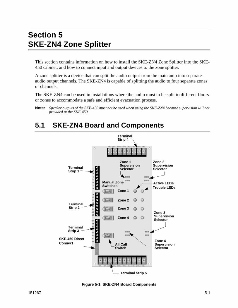
5.1 SKE-ZN4 Board and Components
Figure 5-1 SKE-ZN4 Board Components
TerminalStrip 1
TerminalStrip 2
Manual ZoneSwitches
Zone 1
Zone 2
Zone 3
Zone 4
Trouble LEDsActive LEDs
TerminalStrip 3
All CallSwitch
Terminal Strip 5
TerminalStrip 4
Zone 1Supervision Selector
Zone 2Supervision Selector
Zone 3Supervision Selector
Zone 4Supervision Selector
SKE-450 Direct Connect

SKE-Series Voice Evacuation System Installation/Operation Manual
5-2 151267
5.1.1 Terminal Strip 1This section describes what the terminal connections of terminal strip 1 are used for.
5.1.2 Terminal Strip 2This section describes what the terminal connections of terminal strip 2 are used for.
5.1.3 Terminal Strip 3This section describes what the terminal connections of terminal strip 3 are used for.
Terminal Number
Name Description
1 +24 VDC Positive 24 VDC in or out.
2 GND Ground
3
4
Not Used5
6
7
8 GND Ground
Terminal Number
Name Description
9 GND Ground
10 Alarm Active Signal input from main DMR to indicate when an Alarm occurs. Active low.
11 Alarm Select 1
Used by FACP for automatic alarm control of zone outputs. Active low.12 Alarm Select 2
13 Alarm Select 3
14 Alarm Select 4
15 GND Ground
16 Trouble Out Trouble output, active low.
Terminal Number
Name Description
17 GND Ground
18 Not Used.
19
Not Used.20
21
22
23 GND Ground
24 Select All Not Used.
SKE-ZN4 Zone Splitter
151267 5-3
5.1.4 Terminal Strip 4This section describes what the terminal connections of terminal strip 4 are used for.
5.1.5 Terminal Strip 5This section describes what the terminal connections of terminal strip 5 are used for.
5.1.6 Manual Zone SwitchesManual zone switches are used to manually override the system message by zone, using the microphone.
For example, if you wish to manually give a verbal evacuation message (using the microphone) to zone 4, you would turn on switch 4, then key the microphone and speak the desired message. Your spoken message would be output to the speakers in zone 4 only.
Terminal Name Description
SP1 + Speaker output 1 positive connection.
SP1 – Speaker output 1 negative connection.
SPR1 + Speaker 1 return positive connection, used for Class A (Style Z) configuration.
SPR1 – Speaker 1 return negative connection, used for Class A (Style Z) configuration.
SP2 + Speaker output 2 positive connection.
SP2 – Speaker output 2 negative connection.
SPR2 + Speaker 2 return positive connection, used for Class A (Style Z) configuration.
SPR2 – Speaker 2 return negative connection, used for Class A (Style Z) configuration.
Terminal Name Description
SP +Raw speaker signal from DMR (un-split), used for End of Line supervision.
SP –
SP4 + Speaker output 4 positive connection.
SP4 – Speaker output 4 negative connection.
SPR4 + Speaker 4 return positive connection, used for Class A (Style Z) configuration.
SPR4 – Speaker 4 return negative connection, used for Class A (Style Z) configuration.
SP3 + Speaker output 3 positive connection.
SP3 – Speaker output 3 negative connection.
SPR3 + Speaker 3 return positive connection, used for Class A (Style Z) configuration.
SPR3 – Speaker 3 return negative connection, used for Class A (Style Z) configuration.

SKE-Series Voice Evacuation System Installation/Operation Manual
5-4 151267
5.1.7 All Call SwitchThe All Call Switch manually overrides the system message, using the microphone, to all zones in the system.
5.1.8 Zone Supervision SelectorsThe zone supervision selector selects how the speaker circuit will be supervised. Speaker circuits can be Class B (Style Y) or Class A (Style Z) supervised depending on how they are connected to the control panel. (See Section 5.4 for wiring configurations.)
Figure 5-2 Speaker circuit Supervision Selections
5.1.9 LED DescriptionsThe SKE-ZN4 has two LEDs for each zone, an Active and a Trouble LED. The Active LED (Red) indicates that the zone is activated when it is ON. The Trouble LED (Yellow), when on, indicates the 15 kΩ end of line resistor on the speaker circuit is missing.
5.2 SKE-ZN4 Electrical Specifications
Circuit Rating
Operating Voltage: 24 VDC
Current Draw:Standby: 45 mA
Alarm: All channels active 250 mA
SKE-ZN4 Zone Splitter
151267 5-5
5.3 Mounting the SKE-ZN4 In the SKE-450 Cabinet
This section contains instructions on how to install the SKE-ZN4 Zone Splitter into the SKE-450 Voice Evacuation cabinet.
Follow these steps to install the SKE-ZN4 into the SKE-450 cabinet:
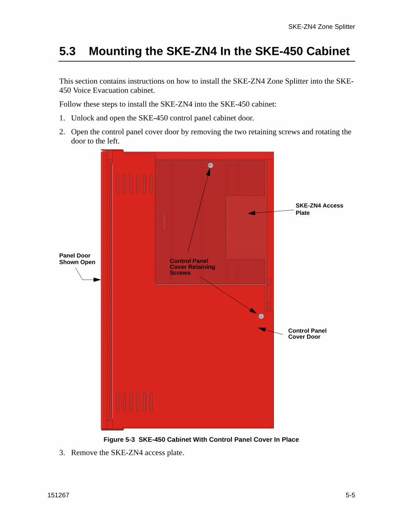
1. Unlock and open the SKE-450 control panel cabinet door.
2. Open the control panel cover door by removing the two retaining screws and rotating the door to the left.
Figure 5-3 SKE-450 Cabinet With Control Panel Cover In Place
3. Remove the SKE-ZN4 access plate.
Control PanelCover RetainingScrews
Control PanelCover Door
SKE-ZN4 Access Plate
Panel DoorShown Open

SKE-Series Voice Evacuation System Installation/Operation Manual
5-6 151267
4. Mount the SKE-ZN4 to the SKE-450 cabinet mounting standoffs with the 7/10” screw-in standoffs provided.
Figure 5-4 SKE-ZN4 Mounting Standoff Locations
5. Connect wiring harness to the expansion connector on the SKE-450 and to the direct connect pins on the SKE-ZN4. See Figure 5-5.
Figure 5-5 View With SKE-ZN4 Installed
6. Wire speaker to zone outputs as required by the installation specifications. Refer to Section 5.4.
7. Attach the SKE-ZN4 cover plate to the SKE-ZN4. See Figure 5-5.
SKE-ZN4 Mounting Standoffs
15 kΩ EOLUL Listed
Model 7630Wiring Harness (P/N 130427)
SKE-ZN4 Cover Plate

SKE-ZN4 Zone Splitter
151267 5-7
5.4 Speaker Wiring
Each SKE-ZN4 supplies four Notification Appliance Circuits for speaker connection. The circuits can be supervised and wired Class B (Style Y) or Class A (Style Z). Each circuit is capable of 50 watts of power. Note: The system can support a maximum of 50 watts of power.
5.4.1 Wiring ProcedureIn order to gain access to the terminals on the SKE-ZN4, the cover plate must be removed. See Figure 5-5.
5.4.2 Class B (Style Y)Figure 5-6 illustrates how to wire speakers to the control panel using Class B (Style Y) supervision. Make sure that the Speaker Circuit Supervision Selector is in the Class B (Style Y) position. See Figure 5-2 for Speaker Circuit Supervision Selections.
Figure 5-6 Class B (Style Y) Speaker Configuration
Note: Figure 5-6 uses Speaker Circuit 1 as an example of the wiring. All other speaker circuits are configured to their respective terminals in the same manner.
SupervisedPower Limited
15 kΩ EOLUL Listed
Model 7630
SKE-Series Voice Evacuation System Installation/Operation Manual
5-8 151267
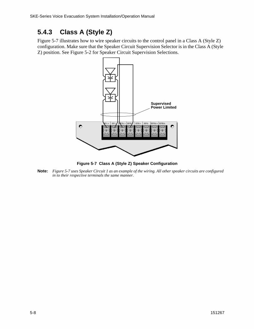
5.4.3 Class A (Style Z)Figure 5-7 illustrates how to wire speaker circuits to the control panel in a Class A (Style Z) configuration. Make sure that the Speaker Circuit Supervision Selector is in the Class A (Style Z) position. See Figure 5-2 for Speaker Circuit Supervision Selections.
Figure 5-7 Class A (Style Z) Speaker Configuration
Note: Figure 5-7 uses Speaker Circuit 1 as an example of the wiring. All other speaker circuits are configured in to their respective terminals the same manner.
SupervisedPower Limited

SKE-ZN4 Zone Splitter
151267 5-9
5.4.4 FACP Alarm Control WiringThis section describes how to connect relay outputs from a FACP to control the four separate zones on the SKE-ZN4 four zone splitter.
Connect an active low relay or contact from the FACP to the Alarm Selects on the SKE-ZN4 (see Figure 5-8).
Figure 5-8 FACP Alarm Control Outputs
SupervisedPower Limited
Non-SupervisedPower Limited
4.7 kΩUL Listed EOLModel 7628
Must be wiredwithin 20 feetand in conduit.

SKE-Series Voice Evacuation System Installation/Operation Manual
5-10 151267

151267 6-1
Section 6SKE-SRM
The SKE-SRM is a supervised remote microphone assembly that can be added to the SKE-Series voice evacuation system.
Figure 6-1 The SKE-SRM
6.1 Specifications
Parameter Rating
Operating Voltage: 24 VDC
Current Draw: Standby: 30 mA
Dimensions:
Height: 10-1/4” (26.04 cm)
Width: 10-3/8” (26.35 cm)
Depth: 3-1/8” (7.94 cm)
Operating Temperature: 0°C-49°C (32°F-120°F)
Microphone
LEDs
MicrophoneConnector
Cover PlateScrews
Cover PlateScrews
CoverPlate

SKE-Series Voice Evacuation System Installation/Operation Manual
6-2 151267
6.2 LED Description
6.3 Installation Instruction
This section contains the information needed to properly install the SKE-SRM.
6.3.1 Mounting the SKE-SRM Cabinet.It is important to protect the SKE-SRM control panel from water. To prevent water damage, the following conditions should be avoided when installing the units:
• Do not mount directly on exterior walls, especially masonry walls (condensation)
• Do not mount directly on exterior walls below grade (condensation)
• Protect from plumbing leaks
• Protect from splash caused by sprinkler inspection ports
• Do not mount in areas with humidity-generating equipment (such as dryers, production machinery)
When selecting a location to mount the SKE-SRM cabinet, the unit should be mounted where it will NOT be exposed to temperatures outside the range of 0°C-49°C (32°F-120°F) or humidity outside the range of 10%-85% at 30°C (86°F) noncondensing.
Follow these steps to mount the remote microphone cabinet:
1. Remove the SKE-SRM from it’s packing container.
2. Unlock the cabinet and remove the cabinet door.
3. Unplug microphone from microphone connector. See Figure 6-1.
Place microphone in a safe location while completing cabinet installation.
4. Remove the cover plate by un-screwing the four cover plate screws (see Figure 6-1). Set the screws aside for later use.
5. Remove the remote microphone chassis assembly by un-screwing the two chassis assem-bly screws. See Figure 6-2.
LED State Meaning
Green
On Remote microphone has DC power.
Off Remote microphone has no power or has a major malfunction.
YellowOn No microphone attached to the unit.
Off Microphone is connected.
Important! The electronic components on the control panel are sensitive to electrostatic discharge (static electricity). Wear a grounding strap when handling the control board.

SKE-SRM
151267 6-3
Figure 6-2 Remote Microphone Chassis Assembly
6. Mount the cabinet using the appropriate screws and anchors, through the cabinet mounting holes. See Figure 6-3.
Figure 6-3 Cabinet Mounting Hole Locations
7. Run any wires needed for the installation. See Section 6.3.2 for more information about wire requirements.
ChassisMountingScrew
ChassisMountingScrew
Cabinet MountingHoles
CabinetMountingHoles
SKE-Series Voice Evacuation System Installation/Operation Manual
6-4 151267
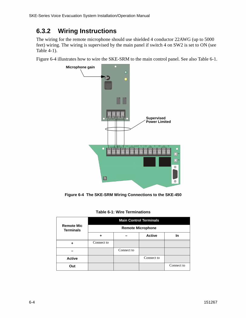
6.3.2 Wiring InstructionsThe wiring for the remote microphone should use shielded 4 conductor 22AWG (up to 5000 feet) wiring. The wiring is supervised by the main panel if switch 4 on SW2 is set to ON (see Table 4-1).
Figure 6-4 illustrates how to wire the SKE-SRM to the main control panel. See also Table 6-1.
Figure 6-4 The SKE-SRM Wiring Connections to the SKE-450
Table 6-1: Wire Terminations
Remote Mic Terminals
Main Control Terminals
Remote Microphone
+ – Active In
+ Connect to
– Connect to
Active Connect to
Out Connect to
SupervisedPower Limited
Microphone gain

SKE-SRM
151267 6-5
6.3.3 Remote Microphone OperationUse the mic gain on the board to adjust audio to desired level. See Figure 6-4 for mic gain location. The system can support a maximum of one remote microphone.
Table 6-2 describes the remote microphones LEDS.
Main mic on the SKE-450 overrides the remote mic.
In normal mode, remote microphone can be used for emergency use only. Voice will be broadcasted via the main panel.
In alarm mode, the remote microphone can be used to interrupt any prerecorded messages to allow manual evacuation. The remote microphone will operate in an "ALL-CALL" mode.
Table 6-2: LED Descriptions
LED Color State Meaning
GreenOn The remote microphone has DC power.
Off No DC power.
YellowOn
Local trouble, indicating that the microphone is not plug into the remote microphone jack.
Off Microphone is connected properly.

SKE-Series Voice Evacuation System Installation/Operation Manual
6-6 151267
151267 7-1
Section 7SKE-V70 Module Installation
The SKE-V70 converts the speaker circuit voltage from 25 Vrms to 70.7 Vrms. The following sections describe how to install and wire the SKE-V70.
7.1 Mounting
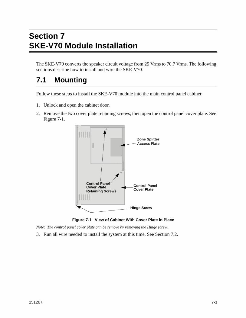
Follow these steps to install the SKE-V70 module into the main control panel cabinet:
1. Unlock and open the cabinet door.
2. Remove the two cover plate retaining screws, then open the control panel cover plate. See Figure 7-1.
Figure 7-1 View of Cabinet With Cover Plate in Place
Note: The control panel cover plate can be remove by removing the Hinge screw.
3. Run all wire needed to install the system at this time. See Section 7.2.
Control PanelCover Plate Control Panel
Cover Plate
Zone SplitterAccess Plate
Retaining Screws
Hinge Screw
SKE-Series Voice Evacuation System Installation/Operation Manual
7-2 151267
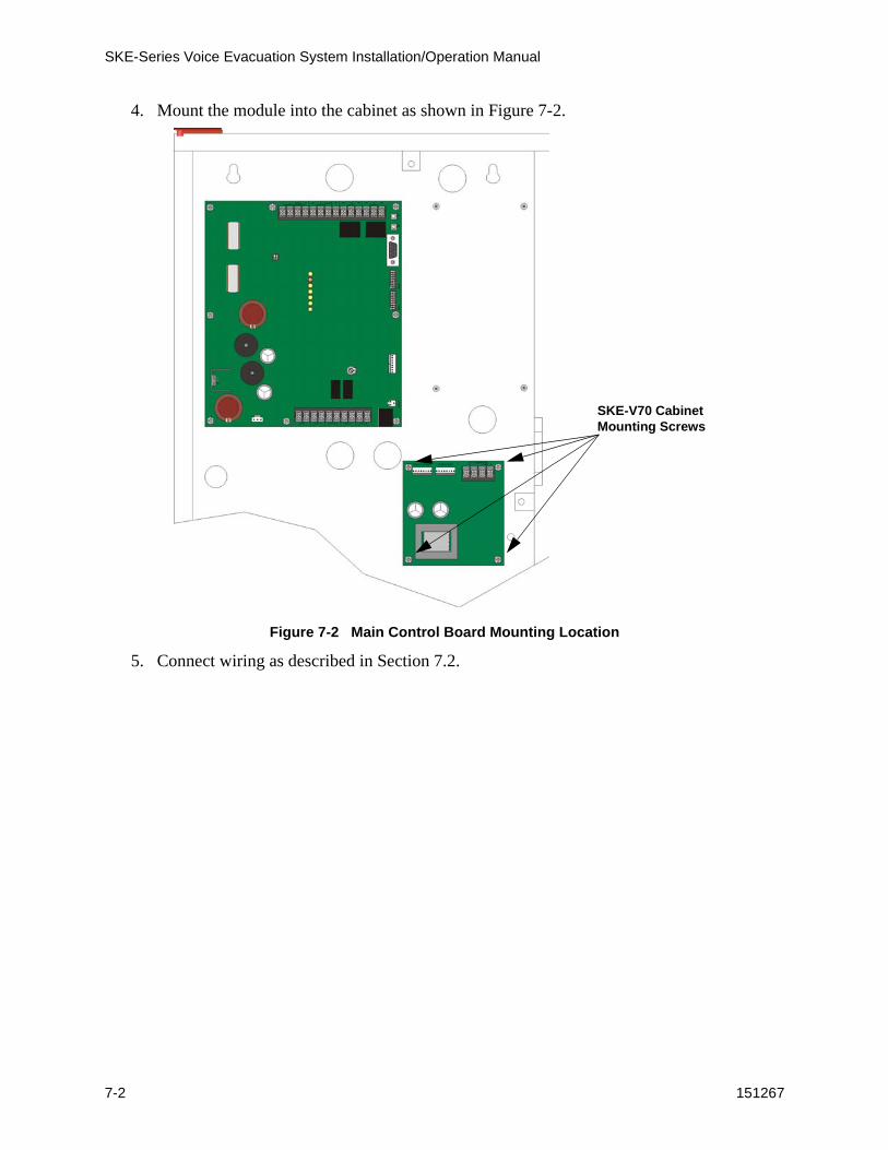
4. Mount the module into the cabinet as shown in Figure 7-2.
Figure 7-2 Main Control Board Mounting Location
5. Connect wiring as described in Section 7.2.
SKE-V70 Cabinet Mounting Screws
SKE-V70 Module Installation
151267 7-3
7.2 Speaker Wiring
Each SKE-V70 supplies one NAC (Notification Appliance Circuit) for speaker connection. The speaker circuit can be supervised and wired Class B (Style Y) or Class A (Style Z). The speaker circuit is capable of 50 watts of power 70.7 Vrms (using the SKE-V70 Module). Refer to Table 3-6 for wire lengths.
Note: When the SKE-V70 Module is installed, all speaker wiring must be separated by a minimum of 1/4” from the low voltage wiring, and must exit the cabinet through its own opening.
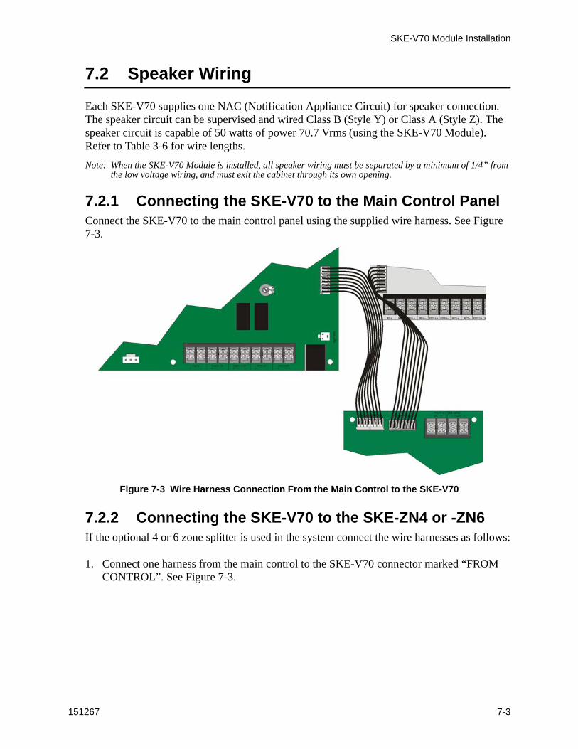
7.2.1 Connecting the SKE-V70 to the Main Control PanelConnect the SKE-V70 to the main control panel using the supplied wire harness. See Figure 7-3.
Figure 7-3 Wire Harness Connection From the Main Control to the SKE-V70
7.2.2 Connecting the SKE-V70 to the SKE-ZN4 or -ZN6If the optional 4 or 6 zone splitter is used in the system connect the wire harnesses as follows:
1. Connect one harness from the main control to the SKE-V70 connector marked “FROM CONTROL”. See Figure 7-3.
SKE-Series Voice Evacuation System Installation/Operation Manual
7-4 151267
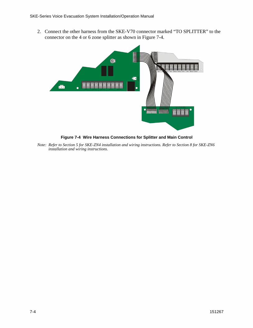
2. Connect the other harness from the SKE-V70 connector marked “TO SPLITTER” to the connector on the 4 or 6 zone splitter as shown in Figure 7-4.
Figure 7-4 Wire Harness Connections for Splitter and Main Control
Note: Refer to Section 5 for SKE-ZN4 installation and wiring instructions. Refer to Section 8 for SKE-ZN6 installation and wiring instructions.
SKE-V70 Module Installation
151267 7-5
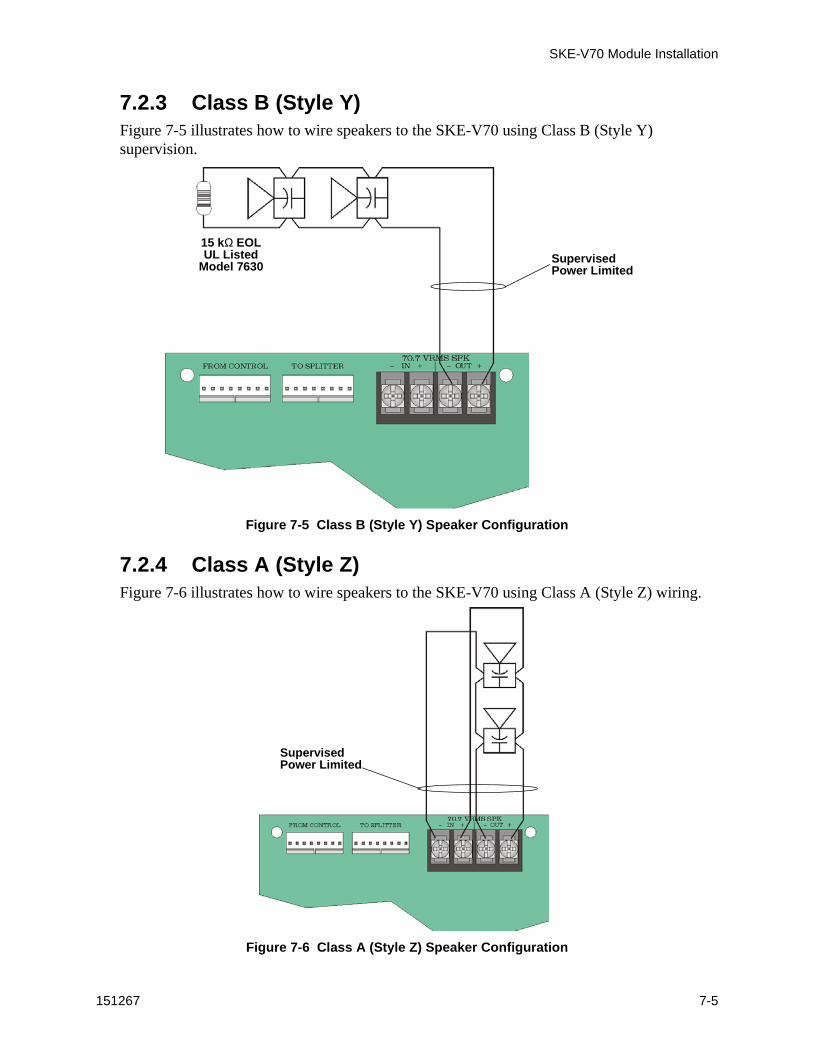
7.2.3 Class B (Style Y)Figure 7-5 illustrates how to wire speakers to the SKE-V70 using Class B (Style Y) supervision.
Figure 7-5 Class B (Style Y) Speaker Configuration
7.2.4 Class A (Style Z)Figure 7-6 illustrates how to wire speakers to the SKE-V70 using Class A (Style Z) wiring.
Figure 7-6 Class A (Style Z) Speaker Configuration
SupervisedPower Limited
15 kΩ EOLUL Listed
Model 7630
SupervisedPower Limited

SKE-Series Voice Evacuation System Installation/Operation Manual
7-6 151267

151150 8-1
Section 8SKE-ZN6 Six Zone Splitter Installation
This section contains information on how to install the SKE-ZN6 Zone Splitter into the SKE-450 cabinet, and how to connect input and output devices to the zone splitter.
A zone splitter is a device that can split the audio output from the main amp into separate audio output channels. The SKE-ZN6 is capable of splitting the audio to six separate zones.
The SKE-ZN6 can be used in installations where the audio needs to be split to different floors or zones to accommodate a safe and efficient evacuation process.
Note: Each speaker circuit is capable of 20 watts maximum power not to exceed 50 watts for the system.
8.1 SKE-ZN6 Board and Components
Figure 8-1 SKE-ZN6 Board Components
TerminalStrip 1
Manual ZoneSwitches
Zone 1
Zone 2
Zone 3
Zone 4
Trouble LEDsActive LEDs
All CallSwitch
Terminal Strip 2
TerminalStrip 3
SKE-450 Direct Connect
Zone 5
Zone 6

SKE-Series Voice Evacuation System Installation/Operation Manual
8-2 151150
8.1.1 Terminal Strip 1This sections describes what the terminal connections of terminal strip 1 are used for.
Terminal Number
Name Description
1 +24 VDC Positive 24 VDC in or out.
2 GND Ground
3 Trouble Out Trouble output, active low.
4 GND Ground
5 Select All Not Used
6Not Used
7
8 GND Ground
9 GND Ground
10 Alarm Active Signal input from main DMR to indicate when an Alarm occurs. Active low.
11 Alarm Select 1
Used by FACP for automatic alarm control of zone outputs. Active low.
12 Alarm Select 2
13 Alarm Select 3
14 Alarm Select 4
15 Alarm Select 5
16 Alarm Select 6
17 GND Ground
18 MIC ActiveSignal input from main DMR to indicate when the microphone has been activated. Active low.
19 Not Used
Not Used
20 Not Used
21 Not Used
22 Not Used
23 Not Used
24 Not Used

SKE-ZN6 Six Zone Splitter Installation
151150 8-3
8.1.2 Terminal Strip 2This sections describes what the terminal connections of terminal strip 5 are used for.
Terminal Name Description
EOL 1Raw speaker signal from DMR (un-split), used for End of Line supervision.
AUDIO1+ Not Used.
–
IN6+ Speaker 6 return positive connection, used for Class A (Style Z) configuration.
– Speaker 6 return negative connection, used for Class A (Style Z) configuration.
OUT6+ Speaker output 6 positive connection, used for Class B (Style Y) configuration.
– Speaker output 6 negative connection, used for Class B (Style Y) configuration.
IN5+ Speaker 5 return positive connection, used for Class A (Style Z) configuration.
– Speaker 5 return negative connection, used for Class A (Style Z) configuration.
OUT5+ Speaker output 5 positive connection, used for Class B (Style Y) configuration.
– Speaker output 5 negative connection, used for Class B (Style Y) configuration.
IN4+ Speaker 4 return positive connection, used for Class A (Style Z) configuration.
– Speaker 4 return negative connection, used for Class A (Style Z) configuration.
OUT4+ Speaker output 4 positive connection, used for Class B (Style Y) configuration.
– Speaker output 4 negative connection, used for Class B (Style Y) configuration..
SKE-Series Voice Evacuation System Installation/Operation Manual
8-4 151150
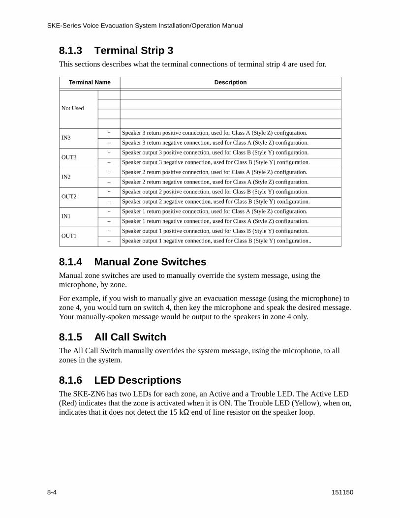
8.1.3 Terminal Strip 3This sections describes what the terminal connections of terminal strip 4 are used for.
8.1.4 Manual Zone SwitchesManual zone switches are used to manually override the system message, using the microphone, by zone.
For example, if you wish to manually give an evacuation message (using the microphone) to zone 4, you would turn on switch 4, then key the microphone and speak the desired message. Your manually-spoken message would be output to the speakers in zone 4 only.
8.1.5 All Call SwitchThe All Call Switch manually overrides the system message, using the microphone, to all zones in the system.
8.1.6 LED DescriptionsThe SKE-ZN6 has two LEDs for each zone, an Active and a Trouble LED. The Active LED (Red) indicates that the zone is activated when it is ON. The Trouble LED (Yellow), when on, indicates that it does not detect the 15 kΩ end of line resistor on the speaker loop.
Terminal Name Description
Not Used
IN3+ Speaker 3 return positive connection, used for Class A (Style Z) configuration.
– Speaker 3 return negative connection, used for Class A (Style Z) configuration.
OUT3+ Speaker output 3 positive connection, used for Class B (Style Y) configuration.
– Speaker output 3 negative connection, used for Class B (Style Y) configuration.
IN2+ Speaker 2 return positive connection, used for Class A (Style Z) configuration.
– Speaker 2 return negative connection, used for Class A (Style Z) configuration.
OUT2+ Speaker output 2 positive connection, used for Class B (Style Y) configuration.
– Speaker output 2 negative connection, used for Class B (Style Y) configuration.
IN1+ Speaker 1 return positive connection, used for Class A (Style Z) configuration.
– Speaker 1 return negative connection, used for Class A (Style Z) configuration.
OUT1+ Speaker output 1 positive connection, used for Class B (Style Y) configuration.
– Speaker output 1 negative connection, used for Class B (Style Y) configuration..

SKE-ZN6 Six Zone Splitter Installation
151150 8-5
8.2 SKE-ZN6 Electrical Specifications
8.3 Mounting the SKE-ZN6 In the SKE-450 Cabinet
This section contains instructions on how to install the SKE-ZN6 Zone Splitter into the SKE450 Voice Evacuation cabinet.
Follow these steps to install the SKE-ZN6 into the SKE450 cabinet:
1. Unlock and open the SKE450 control panel cabinet door.
2. Remove the control panel cover door retaining screws.
Figure 8-2 SKE450 Cabinet With Control Panel Cover In Place
3. Swing the control panel cover door open.
Circuit Rating
Operating Voltage: 24 VDC
Current Draw:Standby: 30 mA
Alarm: All channels active 120 mA
Control PanelCover RetainingScrews
Control PanelCover Door
SKE-ZN6 Access Plate

SKE-Series Voice Evacuation System Installation/Operation Manual
8-6 151150
4. Remove the SKE-ZN6 access plate.
5. Mount the SKE-ZN6 to the SKE450 cabinet mounting standoffs with the 7/10” screw-in standoffs provided.
Figure 8-3 SKE-ZN6 Mounting Standoff Locations
SKE-ZN6 Mounting Standoffs
SKE-ZN6 Six Zone Splitter Installation
151150 8-7
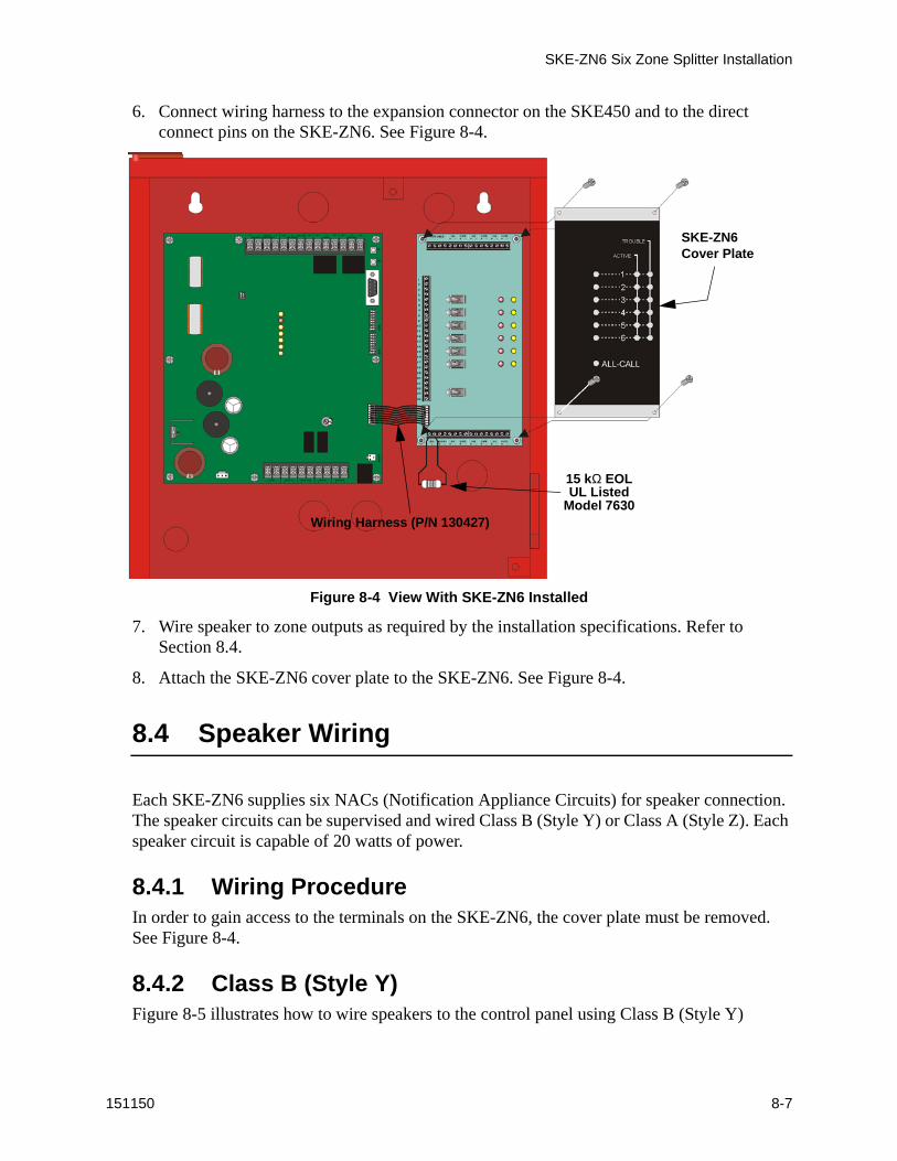
6. Connect wiring harness to the expansion connector on the SKE450 and to the direct connect pins on the SKE-ZN6. See Figure 8-4.
Figure 8-4 View With SKE-ZN6 Installed
7. Wire speaker to zone outputs as required by the installation specifications. Refer to Section 8.4.
8. Attach the SKE-ZN6 cover plate to the SKE-ZN6. See Figure 8-4.
8.4 Speaker Wiring
Each SKE-ZN6 supplies six NACs (Notification Appliance Circuits) for speaker connection. The speaker circuits can be supervised and wired Class B (Style Y) or Class A (Style Z). Each speaker circuit is capable of 20 watts of power.
8.4.1 Wiring ProcedureIn order to gain access to the terminals on the SKE-ZN6, the cover plate must be removed. See Figure 8-4.
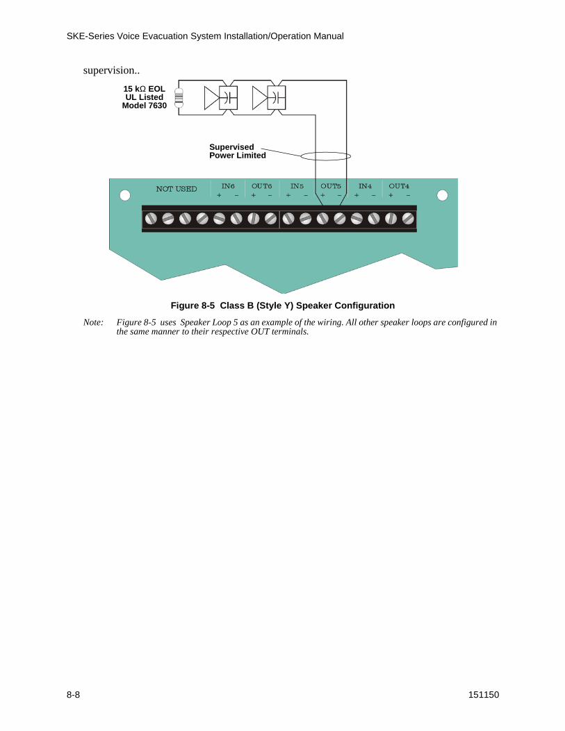
8.4.2 Class B (Style Y)Figure 8-5 illustrates how to wire speakers to the control panel using Class B (Style Y)
15 kΩ EOLUL Listed
Model 7630Wiring Harness (P/N 130427)
SKE-ZN6 Cover Plate
SKE-Series Voice Evacuation System Installation/Operation Manual
8-8 151150
supervision..
Figure 8-5 Class B (Style Y) Speaker Configuration
Note: Figure 8-5 uses Speaker Loop 5 as an example of the wiring. All other speaker loops are configured in the same manner to their respective OUT terminals.
SupervisedPower Limited
15 kΩ EOLUL Listed
Model 7630
SKE-ZN6 Six Zone Splitter Installation
151150 8-9
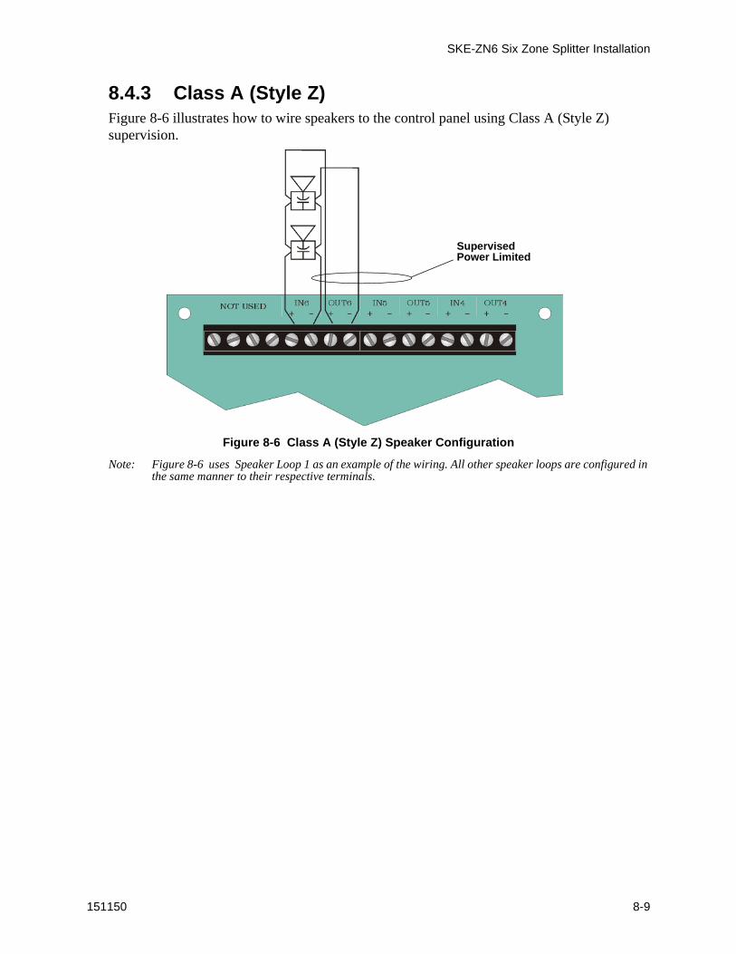
8.4.3 Class A (Style Z)Figure 8-6 illustrates how to wire speakers to the control panel using Class A (Style Z) supervision.
Figure 8-6 Class A (Style Z) Speaker Configuration
Note: Figure 8-6 uses Speaker Loop 1 as an example of the wiring. All other speaker loops are configured in the same manner to their respective terminals.
SupervisedPower Limited
SKE-Series Voice Evacuation System Installation/Operation Manual
8-10 151150
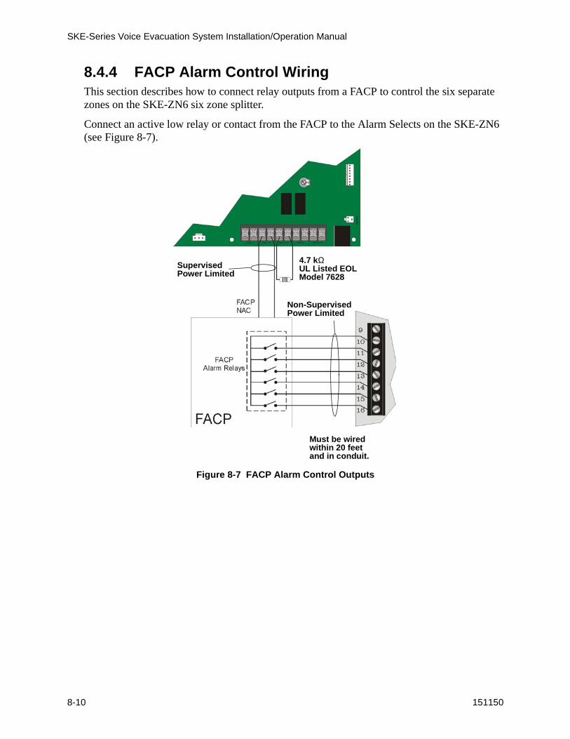
8.4.4 FACP Alarm Control WiringThis section describes how to connect relay outputs from a FACP to control the six separate zones on the SKE-ZN6 six zone splitter.
Connect an active low relay or contact from the FACP to the Alarm Selects on the SKE-ZN6 (see Figure 8-7).
Figure 8-7 FACP Alarm Control Outputs
SupervisedPower Limited
Non-SupervisedPower Limited
4.7 kΩUL Listed EOLModel 7628
Must be wiredwithin 20 feetand in conduit.
151267 9-1
Section 9Battery Calculation
9.1 Calculating Current Draw and Standby Battery
This section enables you to determine the current draw and standby battery needs for your installation (18 Ampere Hours maximum).
Batteries larger then 7 AH will not fit into themain control cabinet, and must be housed in the AB-33 Accessory Battery Cabinet. See Section 3.8.2 for battery installation.
The following is the maximum current draw from the auxiliary power terminals for standby calculations. These currents assume 24 or 60 hours of standby time, followed by 5 minutes of maximum alarm current.
• 195 mA for 24 Hours of Auxiliary Standby Current
• 39 mA for 60 Hours of Auxiliary Standby Current
The above numbers were calculated assuming the use of 7 AH batteries at 100% of rated capacity.
The total current of the control panel, plus all items attached to it, must not exceed 5 A when the panel is in alarm. Use Table 9-1 to ensure that the current does not exceed 5 A and, that the desired amount of standby is possible for the battery intended to be used with the control panel.
The Current Draw Calculations, Table 9-1 (Section 9.1.1)Line A through D have been completed for you. Complete the remaining instructions in Table 9-1 to determine battery size requirements.

151267 9-2
9.1.1 Current Draw TableTable 9-1 shows the current requirements during alarm/battery standby operation.
Table 9-1: Current Draw Calculations
DeviceNumber of
DevicesCurrent per Device
Standby Current
Alarm Current
Main Control Panel 1Standby: 140 mA 140 mA
Alarm: 490 mA 490 mA
SKE-ZN4 1Standby: 45 mA mA
Alarm: All Channels 250 mA mA
SKE-ZN6 1Standby: 35 mA mA
Alarm: All Channels 120 mA mA
SKE-SRM 1Standby: 30 mA mA
Alarm: 30 mA mA
SKE-V70 1Standby: 10 mA mA
Alarm: 65 mA mA
A Current Subtotals: mA mA
Notification Devices Refer to device manual for number of devices and current ratings.
Full Load Alarm: 2000 mA mA
B Current Subtotals: mA mA
C Total current rating of all devices in system (add TOTALS OF A-C) X .001: A A
D Number of standby hours. (24 or 60 for NFPA 72, chapter 1, 1-5.2.5): H
E Multiply lines C (standby current) and D: Total standby AH AH
F Alarm sounding period in hours. (For example, 5 minutes = .0833 hours) H
G Multiply lines E (alarm current) and F: Total alarm AH AH
H Add lines E and G. (AH = Ampere Hours) Total AH required AH

Silent Knight Fire Product Warranty and Return Policy
General Terms and Conditions• All new fire products manufactured by Silent Knight have a limited warranty period of 18
months from the date of manufacture against defects in materials and workmanship. See limited warranty statement for details.
• This limited warranty does not apply to those products that are damaged due to misuse, abuse, negligence, exposer to adverse environmental conditions, or have been modified in any manner whatsoever.
Repair and RA Procedure• All products that are returned to Silent Knight for credit or repair require a RA (Return
Authorization) number. Call Silent Knight Customer Service at 800-446-6444 or 763-493-6435 between 8:00 A.M. and 4:45 P.M. CST, Monday through Friday to obtain a return authorization number. Silent Knight Technical Support is available at 800-328-0103 between 8:00 A.M. and 6:00 P.M. CST, Monday through Friday.
• RA number must be prominently displayed on the outside of the shipping box. See return address example under Advanced Replacement Policy.
• Include a packing slip that has the RA number, a content list, and a detailed description of the problem should be included with each return.
• All products returned to Silent Knight must be sent freight pre-paid. After product is pro-cessed, Silent Knight will pay for shipping product back to customer via UPS ground.
• Return the Silent Knight product circuit board only. Products that are returned in cabinets will be charged an additional $50 to cover the extra shipping and handling costs over board only returns. Do not return batteries. Silent Knight has the authority to determine if a product is repairable. Products that are deemed un-repairable will be returned to the customer.
• Product that is returned that has a board date code more than 18 months from date of man-ufacture will be repaired and the customer will be assessed the standard Silent Knight repair charge for that model.
Advanced Replacement Policy• Silent Knight offers an option of advance replacement for fire product printed circuit
boards that fail during the first 6 months of the warranty period.
• For advance replacement of a defective board contact your local Silent Knight Distributor or call Silent Knight at 800-446-6444 or 763-493-6435 to obtain a RA (Return Authoriza-tion) number and request advanced replacement.
• Customers without a Silent Knight account must use a MasterCard, Visa, or American Express credit card to get an advance replacement.

• A new or refurbished board will be shipped to the customer. The customer will initially be billed for the replacement board but a credit will be issued after the repairable board is received at Silent Knight. All returned products must comply with the guidelines described under “General Terms and Conditions”.
• The defective board must be returned within 30 days of shipment of replacement board for customer to receive credit. No credit will be issued if the returned board was damaged due to misuse or abuse.
• Repairs and returns should be sent to:
Silent Knight
Attn: Repair Department
7550 Meridian Circle Suite 100
Maple Grove, MN 55369-4927
RA Number:___________________
Limited WarrantySilent Knight warrants that the products of its manufacture shall be free from defects in materials or workmanship for 18 months from the manufacturing date code on the printed circuit board, if such goods have been properly installed, are subject to normal proper use, and have not been modified in any manner whatsoever. Upon return of the defective product, Silent Knight will at its sole discretion, either repair or replace, at no cost, such goods as may be of defective material or workmanship. Customers outside the United States are to return products to their distributor for repair.
SILENT KNIGHT SHALL NOT UNDER ANY CIRCUMSTANCES BE LIABLE FOR ANY INCIDENTAL OR CONSEQUENTIAL DAMAGES ARISING FROM LOSS OF PROPERTY OR OTHER DAMAGE OR LOSSES OWING TO THE FAILURE OF SILENT KNIGHT PRODUCTS BEYOND THE COST OF REPAIR OR REPLACEMENT OF ANY DEFECTIVE PRODUCTS.
SILENT KNIGHT MAKES NO WARRANTY OF FITNESS OR MERCHANTABILITY AND NO OTHER WARRANTY, ORAL OR WRITTEN, EXPRESS OR IMPLIED, BEYOND THE 18 MONTH WARRANTY EXPRESSLY SPECIFIED HEREIN.
P/N 151269 Rev. B
Cu
t A
lon
g t
he
Do
tted
Lin
eOperating Instructions
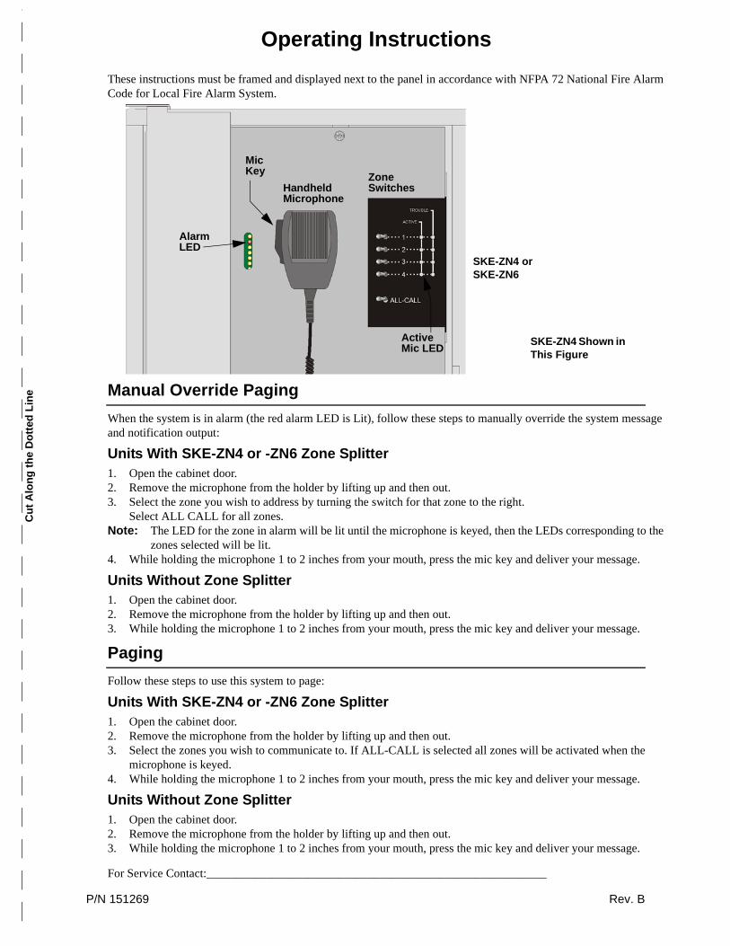
These instructions must be framed and displayed next to the panel in accordance with NFPA 72 National Fire Alarm Code for Local Fire Alarm System.
Manual Override Paging
When the system is in alarm (the red alarm LED is Lit), follow these steps to manually override the system message and notification output:
Units With SKE-ZN4 or -ZN6 Zone Splitter1. Open the cabinet door.2. Remove the microphone from the holder by lifting up and then out.3. Select the zone you wish to address by turning the switch for that zone to the right.
Select ALL CALL for all zones.Note: The LED for the zone in alarm will be lit until the microphone is keyed, then the LEDs corresponding to the
zones selected will be lit.4. While holding the microphone 1 to 2 inches from your mouth, press the mic key and deliver your message.
Units Without Zone Splitter1. Open the cabinet door.2. Remove the microphone from the holder by lifting up and then out.3. While holding the microphone 1 to 2 inches from your mouth, press the mic key and deliver your message.
Paging
Follow these steps to use this system to page:
Units With SKE-ZN4 or -ZN6 Zone Splitter1. Open the cabinet door.2. Remove the microphone from the holder by lifting up and then out.3. Select the zones you wish to communicate to. If ALL-CALL is selected all zones will be activated when the
microphone is keyed.4. While holding the microphone 1 to 2 inches from your mouth, press the mic key and deliver your message.
Units Without Zone Splitter1. Open the cabinet door.2. Remove the microphone from the holder by lifting up and then out.3. While holding the microphone 1 to 2 inches from your mouth, press the mic key and deliver your message.
For Service Contact:_________________________________________________________
Active Mic LED
ZoneSwitchesHandheld
Microphone
AlarmLED
MicKey
SKE-ZN4 or SKE-ZN6
SKE-ZN4 Shown in This Figure

Cu
t A
lon
g t
he
Do
tted
Lin
e

© 2002 Silent KnightPart Number 151267B, 03/02
7550 Meridian CircleMaple Grove, MN 55369-4927763-493-64551-800-328-0103Fax: 763-493-6475


