There is an increasing use of terahertz (THz) radia-tion in a variety of applications, including imaging,remote sensing and security screening, and spectros-copy [1]. The functionality of systems that employTHz radiation might be improved if a low-loss, flex-ible waveguide were available. For example, a low-loss waveguide with good mode selectivity can beused as a cavity for gas sensors and nonlinear appli-cations. Many approaches have been taken to fabri-cate a THz waveguide, including solid-core polymerfibers [2], photonic crystal fibers [3,4], hollow polymerfibers [5], Bragg fibers [6,7], metal tubes [8], sapphirefibers [9], and metal wires [10]. Our earlier work in-volved the deposition of Ag or Cu coatings insidepolycarbonate tubing to form THz waveguides [11].Specifically, we measured a loss of 3.9 dB/m at158.5 �m �1.89 THz� for a 3 mm bore Cu-coated hol-low polycarbonate waveguide. To reduce the loss, it isnecessary to deposit a dielectric coating over the me-tallic film as has been done in the IR region, where,for example, an AgI film was deposited over an Agmetal film [12]. We have chosen to deposit polysty-rene (PS) films over Ag films, as PS has a low loss atTHz frequencies.
A significant challenge in extending metal/dielectric, hollow waveguide technology to THz fre-quencies is that a much thicker dielectric layer is re-quired for low loss. This may be seen from Eq. (1),which shows that for the HE11 mode the optimum di-electric layer thickness, dd, is proportional to the de-sign wavelength, �o:
dd =�o
2��nd2 − 1
tan−1� nd
�nd2 − 1�1/4� , �1�
where nd is the refractive index of the dielectric [12].The wavelength of THz radiation is 10 to 100 timeslonger than IR radiation; hence a corresponding in-crease in film thickness is necessary to achieve low
To prepare THz hollow glass waveguides (HGWs),an Ag film is first deposited within a glass substratetube by combining a solution containing AgNO3 andNH4OH with a reducing solution containing dextroseand Na2EDTA. The glass tubes had bore dimensionsof 1.6, 1.7, and 2.2 mm and were 120 cm long. The Agfilm grows at a rate of approximately 1 �m/h, andour Ag films were normally about 1 �m thick. This ismuch thicker than the skin depth for Ag at THz fre-quencies (100 nm at 119 �m); therefore, no THz ra-diation will penetrate the HGW wall. The PS filmswere deposited over the Ag coatings by using a liquid-flow coating process [13] in which a PS/toluene solu-tion is drawn through the HGW at a constant coatingvelocity by a peristaltic pump. Typical parametersthat we used were a coating velocity of 4 cm/min, aconcentration of 25 wt. % PS, and a viscosity of0.23 Pa s.
The spectrum of a Ag/PS HGW exhibits interfer-ence peaks at wavelengths, �m, given by
�m =dps�4�n2 − 1�
m, �2�
where dps is the thickness of the PS film, n is the re-fractive index of the PS film, and m is a positive in-teger that corresponds to the order of the interfer-ence peak [13]. Rearranging Eq. (2), we obtain anexpression for dps in terms of the difference in wave-number, �̃m− �̃m−1, between any two adjacent interfer-ence peaks,
dps =��̃m − �̃m−1�−1
4�n2 − 1. �3�
We do not have a broadband THz spectrometer, so weuse the spectral response of the Ag/PS HGW in thenear IR to calculate the PS film thickness.
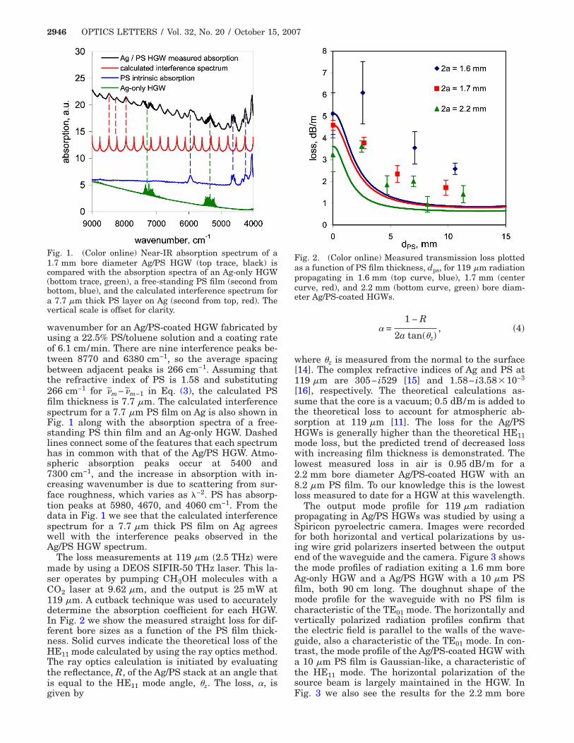
wavenumber for an Ag/PS-coated HGW fabricated byusing a 22.5% PS/toluene solution and a coating rateof 6.1 cm/min. There are nine interference peaks be-tween 8770 and 6380 cm−1, so the average spacingbetween adjacent peaks is 266 cm−1. Assuming thatthe refractive index of PS is 1.58 and substituting266 cm−1 for �̃m− �̃m−1 in Eq. (3), the calculated PSfilm thickness is 7.7 �m. The calculated interferencespectrum for a 7.7 �m PS film on Ag is also shown inFig. 1 along with the absorption spectra of a free-standing PS thin film and an Ag-only HGW. Dashedlines connect some of the features that each spectrumhas in common with that of the Ag/PS HGW. Atmo-spheric absorption peaks occur at 5400 and7300 cm−1, and the increase in absorption with in-creasing wavenumber is due to scattering from sur-face roughness, which varies as �−2. PS has absorp-tion peaks at 5980, 4670, and 4060 cm−1. From thedata in Fig. 1 we see that the calculated interferencespectrum for a 7.7 �m thick PS film on Ag agreeswell with the interference peaks observed in theAg/PS HGW spectrum.
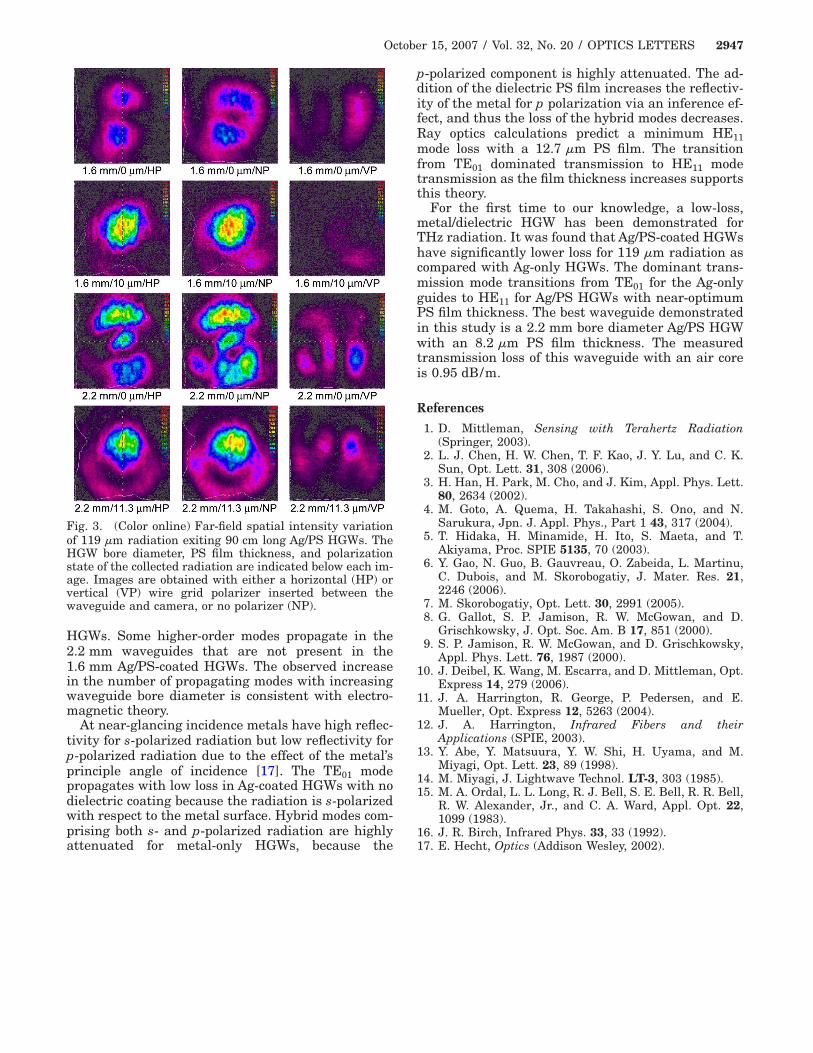
The loss measurements at 119 �m �2.5 THz� weremade by using a DEOS SIFIR-50 THz laser. This la-ser operates by pumping CH3OH molecules with aCO2 laser at 9.62 �m, and the output is 25 mW at119 �m. A cutback technique was used to accuratelydetermine the absorption coefficient for each HGW.In Fig. 2 we show the measured straight loss for dif-ferent bore sizes as a function of the PS film thick-ness. Solid curves indicate the theoretical loss of theHE11 mode calculated by using the ray optics method.The ray optics calculation is initiated by evaluatingthe reflectance, R, of the Ag/PS stack at an angle thatis equal to the HE11 mode angle, �z. The loss, �, is
Fig. 1. (Color online) Near-IR absorption spectrum of a1.7 mm bore diameter Ag/PS HGW (top trace, black) iscompared with the absorption spectra of an Ag-only HGW(bottom trace, green), a free-standing PS film (second frombottom, blue), and the calculated interference spectrum fora 7.7 �m thick PS layer on Ag (second from top, red). Thevertical scale is offset for clarity.
given by
� =1 − R
2a tan��z�, �4�
where �z is measured from the normal to the surface[14]. The complex refractive indices of Ag and PS at119 �m are 305− i529 [15] and 1.58− i3.58�10−3
[16], respectively. The theoretical calculations as-sume that the core is a vacuum; 0.5 dB/m is added tothe theoretical loss to account for atmospheric ab-sorption at 119 �m [11]. The loss for the Ag/PSHGWs is generally higher than the theoretical HE11mode loss, but the predicted trend of decreased losswith increasing film thickness is demonstrated. Thelowest measured loss in air is 0.95 dB/m for a2.2 mm bore diameter Ag/PS-coated HGW with an8.2 �m PS film. To our knowledge this is the lowestloss measured to date for a HGW at this wavelength.
The output mode profile for 119 �m radiationpropagating in Ag/PS HGWs was studied by using aSpiricon pyroelectric camera. Images were recordedfor both horizontal and vertical polarizations by us-ing wire grid polarizers inserted between the outputend of the waveguide and the camera. Figure 3 showsthe mode profiles of radiation exiting a 1.6 mm boreAg-only HGW and a Ag/PS HGW with a 10 �m PSfilm, both 90 cm long. The doughnut shape of themode profile for the waveguide with no PS film ischaracteristic of the TE01 mode. The horizontally andvertically polarized radiation profiles confirm thatthe electric field is parallel to the walls of the wave-guide, also a characteristic of the TE01 mode. In con-trast, the mode profile of the Ag/PS-coated HGW witha 10 �m PS film is Gaussian-like, a characteristic ofthe HE11 mode. The horizontal polarization of thesource beam is largely maintained in the HGW. In
Fig. 2. (Color online) Measured transmission loss plottedas a function of PS film thickness, dps, for 119 �m radiationpropagating in 1.6 mm (top curve, blue), 1.7 mm (centercurve, red), and 2.2 mm (bottom curve, green) bore diam-eter Ag/PS-coated HGWs.
Fig. 3 we also see the results for the 2.2 mm bore
HGWs. Some higher-order modes propagate in the2.2 mm waveguides that are not present in the1.6 mm Ag/PS-coated HGWs. The observed increasein the number of propagating modes with increasingwaveguide bore diameter is consistent with electro-magnetic theory.
At near-glancing incidence metals have high reflec-tivity for s-polarized radiation but low reflectivity forp-polarized radiation due to the effect of the metal’sprinciple angle of incidence [17]. The TE01 modepropagates with low loss in Ag-coated HGWs with nodielectric coating because the radiation is s-polarizedwith respect to the metal surface. Hybrid modes com-prising both s- and p-polarized radiation are highly
Fig. 3. (Color online) Far-field spatial intensity variationof 119 �m radiation exiting 90 cm long Ag/PS HGWs. TheHGW bore diameter, PS film thickness, and polarizationstate of the collected radiation are indicated below each im-age. Images are obtained with either a horizontal (HP) orvertical (VP) wire grid polarizer inserted between thewaveguide and camera, or no polarizer (NP).
attenuated for metal-only HGWs, because the
p-polarized component is highly attenuated. The ad-dition of the dielectric PS film increases the reflectiv-ity of the metal for p polarization via an inference ef-fect, and thus the loss of the hybrid modes decreases.Ray optics calculations predict a minimum HE11mode loss with a 12.7 �m PS film. The transitionfrom TE01 dominated transmission to HE11 modetransmission as the film thickness increases supportsthis theory.
For the first time to our knowledge, a low-loss,metal/dielectric HGW has been demonstrated forTHz radiation. It was found that Ag/PS-coated HGWshave significantly lower loss for 119 �m radiation ascompared with Ag-only HGWs. The dominant trans-mission mode transitions from TE01 for the Ag-onlyguides to HE11 for Ag/PS HGWs with near-optimumPS film thickness. The best waveguide demonstratedin this study is a 2.2 mm bore diameter Ag/PS HGWwith an 8.2 �m PS film thickness. The measuredtransmission loss of this waveguide with an air coreis 0.95 dB/m.
References
1. D. Mittleman, Sensing with Terahertz Radiation(Springer, 2003).
2. L. J. Chen, H. W. Chen, T. F. Kao, J. Y. Lu, and C. K.Sun, Opt. Lett. 31, 308 (2006).
3. H. Han, H. Park, M. Cho, and J. Kim, Appl. Phys. Lett.80, 2634 (2002).
4. M. Goto, A. Quema, H. Takahashi, S. Ono, and N.Sarukura, Jpn. J. Appl. Phys., Part 1 43, 317 (2004).
5. T. Hidaka, H. Minamide, H. Ito, S. Maeta, and T.Akiyama, Proc. SPIE 5135, 70 (2003).
6. Y. Gao, N. Guo, B. Gauvreau, O. Zabeida, L. Martinu,C. Dubois, and M. Skorobogatiy, J. Mater. Res. 21,2246 (2006).
7. M. Skorobogatiy, Opt. Lett. 30, 2991 (2005).8. G. Gallot, S. P. Jamison, R. W. McGowan, and D.
Grischkowsky, J. Opt. Soc. Am. B 17, 851 (2000).9. S. P. Jamison, R. W. McGowan, and D. Grischkowsky,
Appl. Phys. Lett. 76, 1987 (2000).10. J. Deibel, K. Wang, M. Escarra, and D. Mittleman, Opt.
Express 14, 279 (2006).11. J. A. Harrington, R. George, P. Pedersen, and E.
Mueller, Opt. Express 12, 5263 (2004).12. J. A. Harrington, Infrared Fibers and their
Applications (SPIE, 2003).13. Y. Abe, Y. Matsuura, Y. W. Shi, H. Uyama, and M.
Miyagi, Opt. Lett. 23, 89 (1998).14. M. Miyagi, J. Lightwave Technol. LT-3, 303 (1985).15. M. A. Ordal, L. L. Long, R. J. Bell, S. E. Bell, R. R. Bell,
R. W. Alexander, Jr., and C. A. Ward, Appl. Opt. 22,1099 (1983).