29
Simas (LTA) Oil Mist Filter AC 3002 Verification Protocol Oil mist from tooling machine exhaust air September 2009 Project Manager: Marianne Kyed Ørbæk 1

Simas (LTA) Oil Mist Filter AC 3002 Verification Protocol Oil mist from tooling machine exhaust air September 2009 Project Manager: Marianne Kyed Ørbæk
1
1. Table of contents 1. Table of contents ..............................................................................................2 2. Introduction.......................................................................................................3 2.1. Name of product ...............................................................................................3 2.2. Name and contact of vendor.............................................................................3 2.3. Name of centre/verification responsible............................................................3 2.4. Verification and test organization......................................................................3 2.5. Expert group .....................................................................................................4 2.6. Verification process ..........................................................................................4 3. Description of the technology ...........................................................................5 4. Description of the product.................................................................................5 5. Application and performance parameter definitions .........................................7 5.1. Matrix ................................................................................................................7 5.2. Target ...............................................................................................................7 5.3. Effect.................................................................................................................7 5.4. Performance parameters for verification...........................................................7 5.5. Additional parameters.......................................................................................7 6. Existing data .....................................................................................................8 6.1. Summary of existing data .................................................................................8 6.2. Quality of existing data .....................................................................................9 6.3. Accepted existing data......................................................................................9 7. Test plan requirements .....................................................................................9 7.1. Test design .......................................................................................................9 7.2. Reference analysis .........................................................................................10 7.3. Data management ..........................................................................................10 7.4. Quality assurance...........................................................................................10 7.5. Test report ......................................................................................................10 8. Evaluation .......................................................................................................10 8.1. Calculation of performance parameters..........................................................10 8.2. Evaluation of test data quality.........................................................................10 8.3. Compilation of additional parameters .............................................................10 8.3.1. User manual ...................................................................................................10 8.4. Occupational health and environment ............................................................11 9. Verification schedule.......................................................................................11 10. Quality assurance...........................................................................................12 11. References .....................................................................................................12 12. Appendix.........................................................................................................12
2
2. Introduction Environmental technology verification (ETV) is an independent (third party) assessment of the performance of a technology or a product for a specified application, under defined conditions and quality assurance.
2.1. Name of product The product is Simas (LTA) Oil Mist Filter AC 3002.
2.2. Name and contact of vendor Simas Filters A/S Rugvænget 10 8500 Grenaa Denmark Phone +45 8758 1020 Contact Peter Rebsdorf, E-mail [email protected] Cell phone +45 (21) 60 43 49
2.3. Name of centre/verification responsible
Test centre: FORCE Technology Park Allé 345 DK - 2605 Brøndby Denmark.
Verification responsible Ole Schleicher E-mail [email protected] Phone +45 4326 7540 Cell phone +45 2269 7540
2.4. Verification and test organization The verification will be conducted by the Danish test centre DANETV. The verification is planned and conducted to satisfy the requirements of the ETV scheme currently being established by the European Union (EU ETV). Verification and tests will be performed by FORCE Technology as DANETV verification and test centre (VTC). The day to day operations of the verification and tests will be coordinated and supervised by FORCE Technology, with participation of the vendor, Simas Filters A/S. The testing will be conducted in the FORCE Technology laboratories, Brøndby, Denmark. FORCE Technology will operate the oil mist filter during the verification. Simas Filters A/S will provide the oil mist filter, user manuals and operation instructions. In addition also participate in the development of the protocol and plans with FORCE Technology. An expert group is established to support FORCE Technology in planning, conducting and reporting the verification and tests, and to review plans and reports. The organization chart in Figure 1 identifies the relationships of the organization associated with this verification and tests.
3

Figure 1. Organization of the verification and tests
FORCE Technology VTC
Verifications
Simas Filters A/S
Tests
Expert Group
DANETV
2.5. Expert group The expert group assigned to this verification and responsible for review of the verification plan and report documents includes:
Erik Balieu (EB) Balieu Prudentia Dianas Have 75 DK-2970 Hørsholm E-mail [email protected] Phone +45 20 55 17 64 Qualification:
Erik Balieu has an in-depth know-how of filtration theory, filtration mechanisms and performance of filters for removal of air-borne particles. He has more than 30 years of experience in standardization within DS and CEN as well as in testing of respiratory protective devices, including testing of air purifying particle filters for removal of oil aerosols.
Erik Bjarnov (Ekb) Specialist / Chemical Analysis FORCE Technology Park Allé 345 DK-2605 Brøndby E-mail: [email protected] Phone +45 43 26 72 58
Qualification:
Erik Bjarnov has many years of experience with standardisation and testing of respiratory protective equipment including testing of particle filters against oil aerosols.
2.6. Verification process Verification and tests will be conducted in two separate steps, as required by the EU ETV. The steps in the verification are shown in Figure 2.
4

Figure 2. Verification steps
FORCE Technology VTCTest
Verification protocol
Report document
Verification statementVerification
Verification report
Plan document
Test and verification Verificate
Expert Group QA
FORCE Technology VTC
Verification
Test plan Test Test report
Expert Group QA
References for the verification process are the Quality Management Plan for DANETV /1/ A verification statement will be issued after completion of the verification.
3. Description of the technology A wide range of technologies and products are available for removal of aerosols in oil mist from ventilation air. The technology product to be verified is applying the electrostatic precipitation technology for removal of oil mist from exhaust air from metal cutting machines.. The removal of oil mist is based upon electrostatic attraction. By using an electro filter the electrical forces are used to separate the aerosols from the oil. The filtration principle in electrostatic attraction is divided into 3 steps: 1. charging the particles 2. separation of the particles 3. removal of the separated particles
4. Description of the product Simas (LTA) Oil Mist Filter AC 3002 is an electrostatic separator, but the unit is called a filter by the manufacturer. It is developed to remove cooling lubricant oil mist from
5
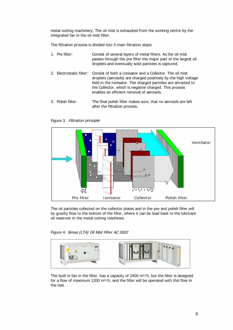
metal cutting machinery. The oil mist is exhausted from the working centre by the integrated fan in the oil mist filter. The filtration process is divided into 3 main filtration steps: 1. Pre filter: Consist of several layers of metal filters. As the oil mist
passes through the pre filter the major part of the largest oil droplets and eventually solid particles is captured.
2. Electrostatic filter: Consist of both a Ionisator and a Collector. The oil mist
droplets (aerosols) are charged positively by the high voltage field in the Ionisator. The charged particles are attracted to the Collector, which is negative charged. This process enables an efficient removal of aerosols.
3. Polish filter: The final polish filter makes sure, that no aerosols are left
after the filtration process.
Figure 3. Filtration principle
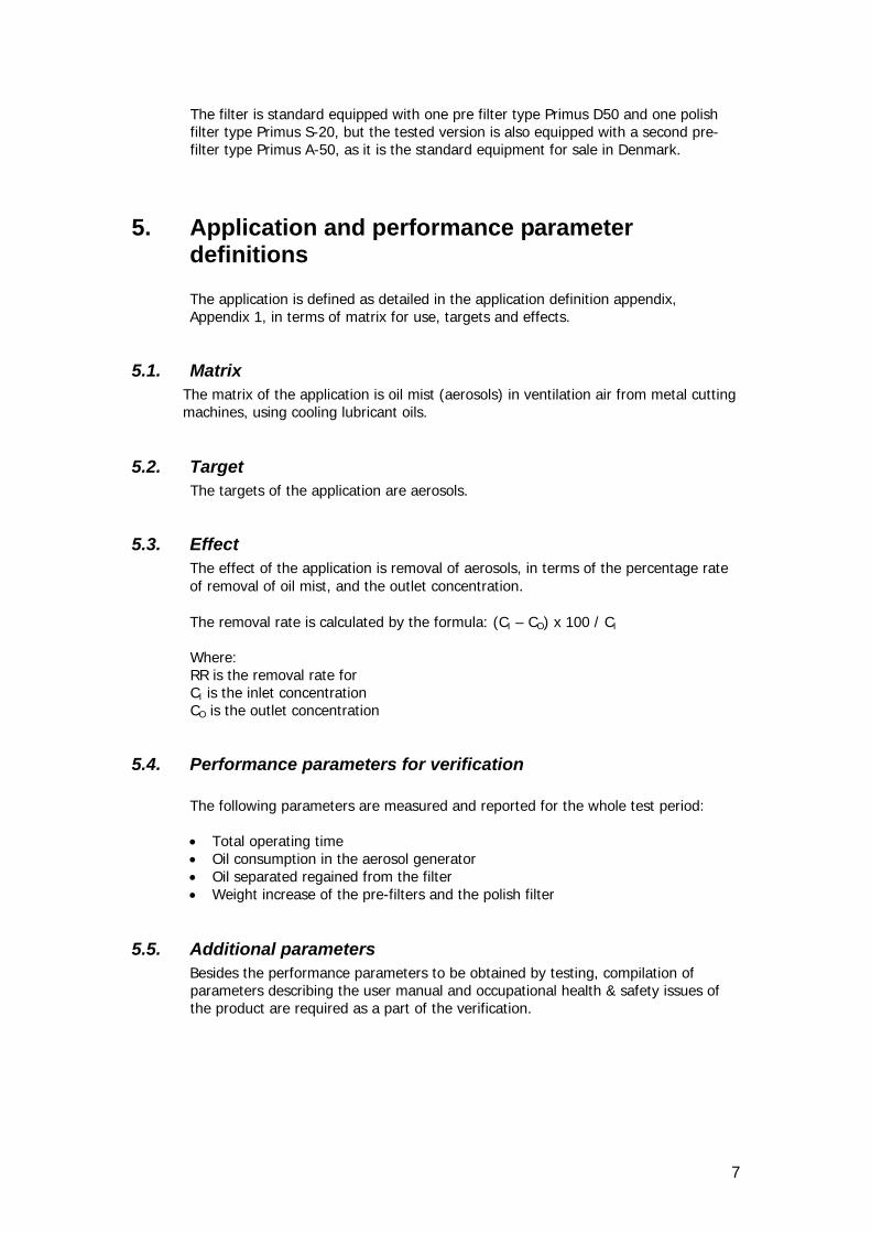
The oil particles collected on the collector plates and in the pre and polish filter will by gravity flow to the bottom of the filter, where it can be lead back to the lubricant oil reservoir in the metal cutting machines. Figure 4. Simas (LTA) Oil Mist Filter AC 3002
Ventilator
Pre filter Ionisator Collector Polish filter
The built in fan in the filter, has a capacity of 2400 m³/h, but the filter is designed for a flow of maximum 1200 m³/h, and the filter will be operated with this flow in the test.
6
The filter is standard equipped with one pre filter type Primus D50 and one polish filter type Primus S-20, but the tested version is also equipped with a second pre-filter type Primus A-50, as it is the standard equipment for sale in Denmark.
5. Application and performance parameter definitions The application is defined as detailed in the application definition appendix, Appendix 1, in terms of matrix for use, targets and effects.
5.1. Matrix The matrix of the application is oil mist (aerosols) in ventilation air from metal cutting machines, using cooling lubricant oils.
5.2. Target The targets of the application are aerosols.
5.3. Effect The effect of the application is removal of aerosols, in terms of the percentage rate of removal of oil mist, and the outlet concentration. The removal rate is calculated by the formula: (CI – CO) x 100 / CI Where: RR is the removal rate for CI is the inlet concentration CO is the outlet concentration
5.4. Performance parameters for verification The following parameters are measured and reported for the whole test period:
• Total operating time • Oil consumption in the aerosol generator • Oil separated regained from the filter • Weight increase of the pre-filters and the polish filter
5.5. Additional parameters Besides the performance parameters to be obtained by testing, compilation of parameters describing the user manual and occupational health & safety issues of the product are required as a part of the verification.
7

6. Existing data Test results from an earlier test with the Oil Mist Filter AC 3002 are available but it doesn’t document the filtration efficiency on a long term basis, which is important in this test.
6.1. Summary of existing data
In October 2008 an AC 3002 R was tested for it ability to remove oil aerosol from air, by ILK Dresden and reported in Fachbericht ILK-B-33-08-1469 dated 24.10.2008. Attached as Appendix 2.
The test conditions were briefly:
• The test aerosols were made by an ATM 243 aerosol generator from Topas. • The test oil used was an KSS Wiolan SH 10 from Houghton • The target for the air flow through the filter was 1260 m³/h • The target for the inlet oil aerosol concentration was 70 mg/m³ • The removal rate was calculated based on data from four samples of oil
aerosol at the inlet and the outlet of the filter. Sampling time was 30 minutes for inlet samples, and 65 minutes for outlet samples.
• Oil aerosol was collected on glass fibre filter, extracted with tetrachloroethene and analysed by FT-IR spectroscopy.
• Aerosol particle size distribution was measured by an SMPS-System Model 3963 from TSI Inc.
• The test aerosol particle size distribution is shown in Figure 5.
Figure 5. Aerosol particle size distribution in the ILK Dresden test
The measured removal rates together with the inlet and outlet aerosol concentration and the air flow for each measurement, are shown in Table 1:
Table 1. Results and removal rate from the ILK Dresden test
8
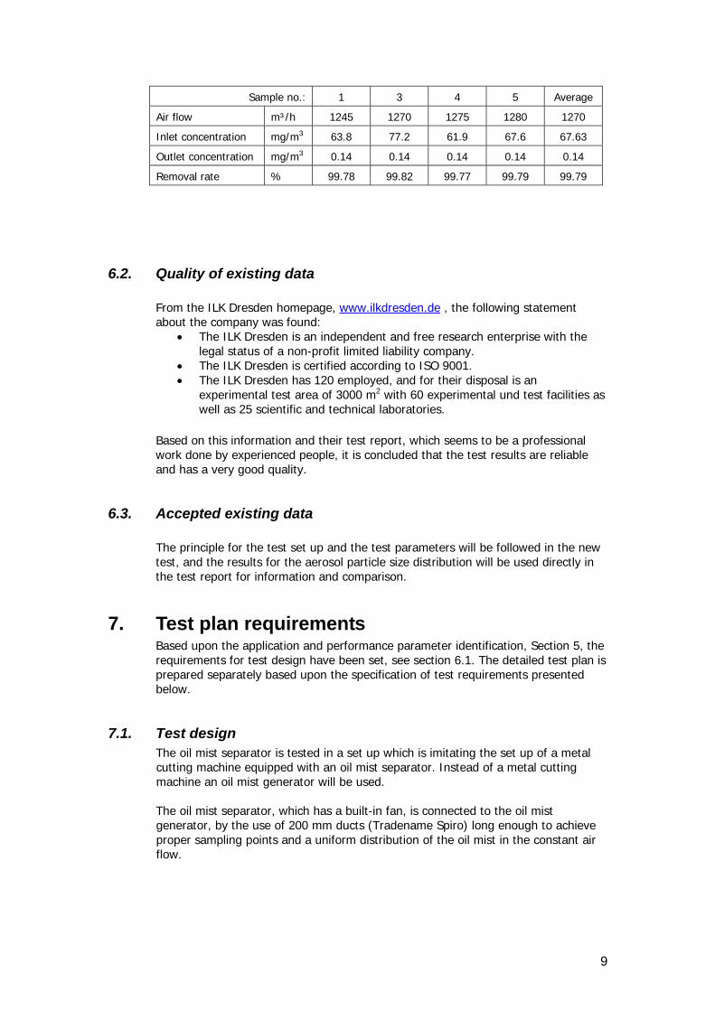
Sample no.: 1 3 4 5 Average
Air flow m³/h 1245 1270 1275 1280 1270
Inlet concentration mg/m3 63.8 77.2 61.9 67.6 67.63
Outlet concentration mg/m3 0.14 0.14 0.14 0.14 0.14
Removal rate % 99.78 99.82 99.77 99.79 99.79
6.2. Quality of existing data From the ILK Dresden homepage, www.ilkdresden.de , the following statement about the company was found:
• The ILK Dresden is an independent and free research enterprise with the legal status of a non-profit limited liability company.
• The ILK Dresden is certified according to ISO 9001. • The ILK Dresden has 120 employed, and for their disposal is an
experimental test area of 3000 m2 with 60 experimental und test facilities as well as 25 scientific and technical laboratories.
Based on this information and their test report, which seems to be a professional work done by experienced people, it is concluded that the test results are reliable and has a very good quality.
6.3. Accepted existing data The principle for the test set up and the test parameters will be followed in the new test, and the results for the aerosol particle size distribution will be used directly in the test report for information and comparison.
7. Test plan requirements Based upon the application and performance parameter identification, Section 5, the requirements for test design have been set, see section 6.1. The detailed test plan is prepared separately based upon the specification of test requirements presented below.
7.1. Test design The oil mist separator is tested in a set up which is imitating the set up of a metal cutting machine equipped with an oil mist separator. Instead of a metal cutting machine an oil mist generator will be used. The oil mist separator, which has a built-in fan, is connected to the oil mist generator, by the use of 200 mm ducts (Tradename Spiro) long enough to achieve proper sampling points and a uniform distribution of the oil mist in the constant air flow.
9
7.2. Reference analysis The test measurement is performed according to FORCE Technology’s DANAK accreditation no. 51 according to ISO 17125 (approved by Danish Standards).
7.3. Data management Data storage, transfer and control must be done in accordance with the requirements of ISO 9001 /2/ enabling full control and retrieval of documents and records.
7.4. Quality assurance The quality assurance of the tests must include control of the reference system, control of the test system and control of the data quality and integrity. The test plan and the test report will be subject to review by the expert group as part of the review of this verification protocol and the verification report, see Figure 2.
7.5. Test report The test report must follow the template of DANETV FORCE Technology verification centre quality manual /1/ with data and records from the tests presented.
8. Evaluation The evaluation includes calculation of the performance parameters, see Section 5.4 for definition, evaluation of the data quality based upon the test quality assurance, see Section 7.4 for requirements, and compilation of the additional parameters as specified in Section 5.5.
8.1. Calculation of performance parameters Calculations are done according to generally accepted mathematical and statistical principles such as those described in /2/ and as described in section 5.3.
8.2. Evaluation of test data quality The uncertainty for the measurement of mineral oil mist is ±15 % of the measured value (95% confidence interval), and all the measured values is checked to be within the range of ±15 % of the average of the measurements.
8.3. Compilation of additional parameters Constant and steady operation and oil mist load during the whole test period is checked by the measured operational parameters, e.g. air flow and temperature, and the daily measured amount of oil filled into the oil mist generator and the oil tapped from the pipes and oil mist filter.
8.3.1. User manual The verification criterion for the users manual is that it describes the use of the electrostatic filter adequately and understandable.
10

A description is complete, if all essential steps are described, if they are illustrated with a figure or a photo, where relevant, and if the descriptions are understandable without reference to other guidance. Table 3 Criteria for user manual evaluation
Parameter Complete description
Summary description
No description
Not relevant
Product
Principle of operation X
Intended use X
Performance expected X
Limitations X
Preparations
Unpacking X
Transport X
Assembly X
Installation X
Function test X
Operation
Steps of operation X
Points of caution X
Maintenance X
Trouble shooting X
Safety
General instructions X
Power and high voltage X
8.4. Occupational health and environment The LTA Oil Mist Filter AC 3002 has the CE mark, which guaranties focus on healthy and safety during productions and use. An electrostatic precipitator has special precautions, because of the very high voltage, and this is clearly explained and repeated in several parts of the users manual.
9. Verification schedule The verification is planned for October 2009. The overall schedule is given in Table 4.
11
Table 4 Verification schedule Task Timing Application definition document May 2009 Verification protocol with test plan September 2009 Test October 2009 Test reporting January 2010 Verification February 2010 Verification report March 2010 Verification statement March 2010
10. Quality assurance The quality assurance of the verification is described in Table 4 and Figure 2, and the quality assurance of the tests in the test plan. Table 5 QA plan for the verification Internal audit Expert Group
Task Initials AGE EB, EKB Plan document with the application definition, verification protocol and test plan
Review Review
Report document with the test report and verification report Review Review
11. References 1. DANETV. Verification Test Centre Quality Manual. 27-2-2009. 2. DANAK accreditation number 51
12. Appendix
Appendix 1 Application and performance parameter definitions Appendix 2 ILK Dresden test report, Fachbericht ILK-B-33-08-1469,
dated 24.10.2008.
12

Simas Filters Verification ReportAppendix 1 Application and performance parameter definitions
1
This appendix defines the application and the relevant performance parameters application as input for verification and test of an environmental technology following the DANETV method.
1. Application The intended application of the product for verification is defined in terms of the matrix, the targets and the effects of the product.
1.1. Matrix The matrix of the application is oil mist (aerosols) in ventilation air from metal cutting machines, using cooling lubricant oils. Several parameters affect the generation and particle distribution of the oil mist from metal cutting machines, e.g. the velocity of the cutting edge, the flow and velocity of the lubricant oil to the cutting point, the temperature, the type and behaviour of the lubricant oil. These parameters are kept constant during the test, by using a standardized test set up, with an oil mist generator.
1.2. Target(s) The targets of the application are oil aerosols.
1.3. Effects The effect of the application is removal of aerosols, in terms of the percentage removal of oil mist, and the outlet concentration. The removal rate is calculated by the formula: RR = (CI – CU) x 100 / CI Where: RR is the removal rate for CI is the inlet concentration CU is the outlet concentration In order to be able to gain reproducible results the test is conducted under standardized and constant conditions imitating usual industrial operating conditions for metal cutting machines. During the test it is expected to observe the effect of: • Decreasing flow rate and or increasing pressure drop across the filter as both pre
and end filter eventually will block more and more. • Some amount of oil on vapour phase.
1.4. Exclusion The variations in the air temperature, humidity and pressure which can occur during the test, is expected to have an insignificant impact on the filter performance, and is thus not covered by the verification. Effect on filter performance if particle distribution is changed (better or worse efficiency?)

Simas Filters Verification ReportAppendix 1 Application and performance parameter definitions
2
2. General performance requirements No formal performance requirements for the application have been identified in the European Union or the US.
2.1. Regulatory requirements
The Danish ELV for oil aerosol is 1 mg/m³ according to the Environmental Guidelines Nr. 1, 2002, Guidelines for Air Emission Regulation – Limitation of air pollution form installations, by sampling and analysis of oil mist according to MEL-14, which is the method recommended by the Danish Environmental Protecting Agency. MEL-14 is a slightly modified US EPA Method 0010, Method for Determining TCO/GRAV in Stack Gas, adjusted for the specific sampling and analysis of mineral oil aerosols.
2.2. Application based requirements Not relevant!
3. State of the art performance Not relevant!
4. Performance parameter definitions No elaborating comments.

ILK Dresden
Zertifiziert nach ISO 9001 Institut für Luft- und Kältetechnik gemeinnützige Gesellschaft mbH Bertolt-Brecht-Allee 20 01309 Dresden Geschäftsführer: Dr. rer. nat. habil. Ralf Herzog Prokurist: Prof. Dr.-Ing. Uwe Franzke Tel.: 0351/4081-520 Fax 0351/4081-525 E-Mail: [email protected] http://www.ilkdresden.de Commerzbank Dresden Kto. 8 000 135. BLZ 850 400 00 Amtsgericht Dresden HRB 6118
Fachbericht ILK-B-33-08-1469 24.10.2008 Seitenzahl 14 Untersuchung von elektrostatischen Abscheidern - Baureihenentwicklung Dipl.- Ing. Ralf Heidenreich Dipl.-Ing. Steffen Blei (Zusammenfassung vom 06.03.09: LTA, Dipl.-Ing. (FH) Jürgen Kälble)

2
ILK-B-33-08-1469
Inhaltsverzeichnis
1 Aufgabenstellung 3
2 Messaufbau und Vorgehensweise 4
2.1 Aufbau des Prüfstandes 4
2.2 Elektrostatische Abscheider 5
2.3 Bestimmung des Gesamtabscheidegrades und Fraktionsabscheidegrades 5
2.4 Partikelmesstechnik 5
2.4.1 Mobilitätsspektrometer Model 3963 5
2.5 Aerosoldosierung 6
3 Bewertung der Versuchsergebnisse 6
3.1 Fraktionsabscheidegrad 8
3.2 Gesamtabscheidegrad bei Nennluftvolumenstrom 10
4 Zusammenfassung und Bewertung 11
3
ILK-B-33-08-1469
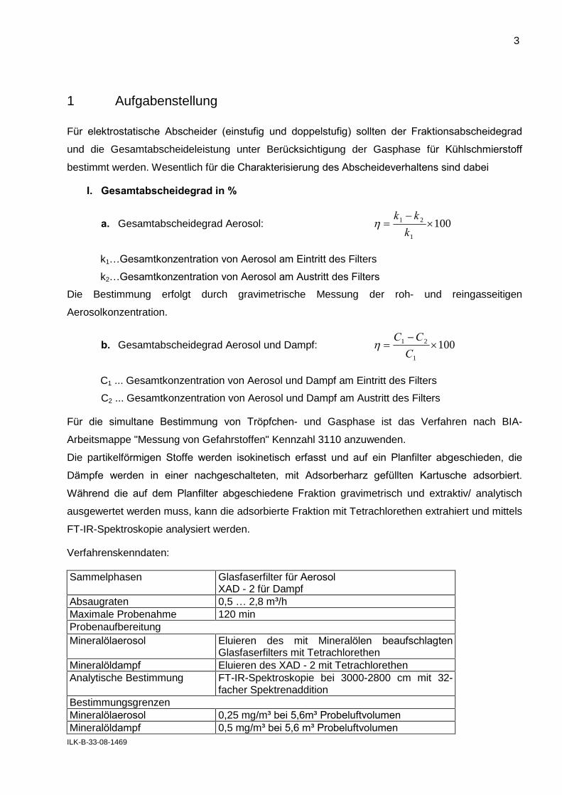
1 Aufgabenstellung
Für elektrostatische Abscheider (einstufig und doppelstufig) sollten der Fraktionsabscheidegrad
und die Gesamtabscheideleistung unter Berücksichtigung der Gasphase für Kühlschmierstoff
bestimmt werden. Wesentlich für die Charakterisierung des Abscheideverhaltens sind dabei
I. Gesamtabscheidegrad in %
a. Gesamtabscheidegrad Aerosol: 1001
21
k
kk
k1�Gesamtkonzentration von Aerosol am Eintritt des Filters
k2�Gesamtkonzentration von Aerosol am Austritt des Filters
Die Bestimmung erfolgt durch gravimetrische Messung der roh- und reingasseitigen
Aerosolkonzentration.
b. Gesamtabscheidegrad Aerosol und Dampf: 1001
21
C
CC
C1 ... Gesamtkonzentration von Aerosol und Dampf am Eintritt des Filters
C2 ... Gesamtkonzentration von Aerosol und Dampf am Austritt des Filters
Für die simultane Bestimmung von Tröpfchen- und Gasphase ist das Verfahren nach BIA-
Arbeitsmappe "Messung von Gefahrstoffen" Kennzahl 3110 anzuwenden.
Die partikelförmigen Stoffe werden isokinetisch erfasst und auf ein Planfilter abgeschieden, die
Dämpfe werden in einer nachgeschalteten, mit Adsorberharz gefüllten Kartusche adsorbiert.
Während die auf dem Planfilter abgeschiedene Fraktion gravimetrisch und extraktiv/ analytisch
ausgewertet werden muss, kann die adsorbierte Fraktion mit Tetrachlorethen extrahiert und mittels
FT-IR-Spektroskopie analysiert werden.
Verfahrenskenndaten:
Sammelphasen Glasfaserfilter für Aerosol XAD - 2 für Dampf
Absaugraten 0,5 � 2,8 m³/h Maximale Probenahme 120 min Probenaufbereitung Mineralölaerosol Eluieren des mit Mineralölen beaufschlagten
Glasfaserfilters mit Tetrachlorethen Mineralöldampf Eluieren des XAD - 2 mit Tetrachlorethen Analytische Bestimmung FT-IR-Spektroskopie bei 3000-2800 cm mit 32-
facher Spektrenaddition Bestimmungsgrenzen Mineralölaerosol 0,25 mg/m³ bei 5,6m³ Probeluftvolumen Mineralöldampf 0,5 mg/m³ bei 5,6 m³ Probeluftvolumen

4
ILK-B-33-08-1469
Für die gesicherte Bestimmung einer Abscheideleistung ist je dreimal roh- und reingasseitig eine
Messung durchzuführen.
II. Fraktionsabscheidegrad des Filters T (x) in %:
Abscheidegrad für eine bestimmte Partikelgröße x: 100)(
)()()(
1
21
xk
xkxkxT
k1(x) ... Partikelanzahlkonzentration der Partikelgröße x am Eintritt des Filters
k2(x) ... Partikelanzahlkonzentration der Partikelgröße x am Austritt des Filters
Mit der Kenngröße des Fraktionsabscheidegrades kann eine Aussage über die Abscheide-
charakteristik des Filters getroffen werden. Der gemessenen Fraktionsabscheidegrad ist abhängig
von der Art des Aerosols.
Mit der Kenngröße des Fraktionsabscheidegrades kann eine Aussage über die Abscheide-
charakteristik des Filters getroffen werden. Der gemessenen Fraktionsabscheidegrad ist abhängig
von der Art des Aerosols.
Die Messungen werden mit dem KSS Wiolan SH 10 der Fa. Houghton durchgeführt. Die
Aerosoldosierung erfolgt mit einem Dosiersystem ATM 243 der Fa. Topas. Die eingestellte KSS-
Konzentration soll 35 bzw. 70 mg/m³ betragen.
Die Anströmgeschwindigkeit ist über den in den Abscheider integrierten Lüfter festgelegt und
beträgt ca. 1250 m³/h. Die Messungen erfolgen im Neuzustand der elektrostatischen Abscheider.
2 Messaufbau und Vorgehensweise
2.1 Aufbau des Prüfstandes
Für die Untersuchungen wurde im ILK Dresden ein separater Prüfstand für die Untersuchung der
elektrostatischen Abscheider eingerichtet. Für die Durchführung der Messungen wurden
Kanalelemente für die Einbindung der elektrostatischen Abscheider und Adapter für die
Anpassung der Abscheider an das ILK-interne Absaugsystem gefertigt, sowie eine Roh- und
Reingasmessstrecke ausgebildet.
Dabei sorgt die Gestaltung der Anlaufstrecke für eine gute Dispergierung des Prüfaerosols über
den Kanalquerschnitt. Für die notwendigen Messstellen wurden entsprechende Sonden- und
Sensorhalterungen vorgesehen.
Tabelle 2-0: Eingesetzte Mess- und Dosiertechnik
Mobilitätsspektrometer Model 3936 Ölnebelgenerator ATM 243 mit Einrichtung zur
Ölnebelhomogenisierung

5
ILK-B-33-08-1469
2.2 Elektrostatische Abscheider
Die untersuchten elektrostatischen Abscheider sind in Tabelle 2- charakterisiert. Die im Abscheider
integrierten Filterelemente sind senkrecht zur Strömungsrichtung angeordnet.
Tabelle 2-1: Eingesetzte Filter
Filterbezeichnung Typ Abmessungen
B x H x L
Rohgas-
konzentration
AC 3001 R Mechanische Vorfiltration 1 elektrostatische Reinigungsstufe 590 x 610 x 740 35 mg/m³
AC 3002 R Mechanische Vorfiltration 2 elektrostatische Reinigungsstufen 590 x 610 x 1065 70 mg/m³
2.3 Bestimmung des Gesamtabscheidegrades und Fraktionsabscheidegrades
Die Bestimmung des Gesamtabscheidegrades erfolgt durch eine gleichzeitige gravimetrische
Messung der roh- und reingasseitigen Aerosolkonzenration.
Die Bestimmung des Fraktionsabscheidegrades erfolgt durch abwechselnde, roh- und
reingasseitige Messung mit dem Mobilitätsspektrometer Model 3936.
2.4 Partikelmesstechnik
2.4.1 Mobilitätsspektrometer Model 3963
Für Partikelgrößen im Nanometerbereich kommt das Mobilitätsspektrometer bestehend aus einem
Elektroklassierer mit langem DMA und Kondensationskernzähler CPC zum Einsatz. In
Abhängigkeit von vorgeschaltetem Impaktor, Probenahmedurchfluß und Probenahmedauer wird
bei den vorliegenden Versuchen mit dem SMPS das Partikelgrößenspektrum von 18 bis 850 nm
abgedeckt. In Tabelle 2-1 ist das verwendete Gerät in seinen Eigenschaften aufgeführt.
Tabelle 2-1: Eingesetzte Partikel- Messtechnik Mobilitätsspektrometer
Größe Messprinzip Messbereich Sensor / Messgerät
Partikel-konzentration Patrikelgrössen-verteilung
Korrelation von Partikelgröße und Mobilität der Partikel, Kondensationskernzählung
0,02 µm ... 1 µm SMPS- System Model 3963 Fa. TSI Inc.
6
ILK-B-33-08-1469
2.5 Aerosoldosierung
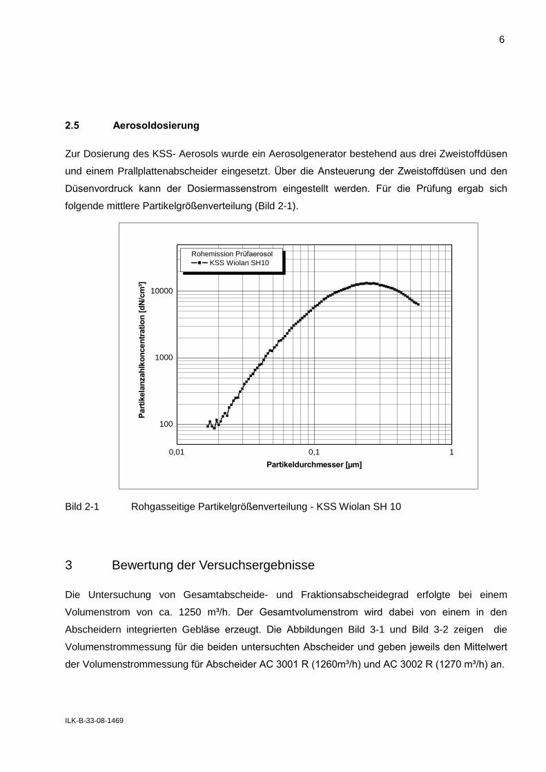
Zur Dosierung des KSS- Aerosols wurde ein Aerosolgenerator bestehend aus drei Zweistoffdüsen
und einem Prallplattenabscheider eingesetzt. Über die Ansteuerung der Zweistoffdüsen und den
Düsenvordruck kann der Dosiermassenstrom eingestellt werden. Für die Prüfung ergab sich
folgende mittlere Partikelgrößenverteilung (Bild 2-1).
0,01 0,1 1
100
1000
10000
Rohemission Prüfaerosol
KSS Wiolan SH10
Part
ikela
nzah
lko
ncen
trati
on
[d
N/c
m³]
Partikeldurchmesser [µm]
Bild 2-1 Rohgasseitige Partikelgrößenverteilung - KSS Wiolan SH 10
3 Bewertung der Versuchsergebnisse
Die Untersuchung von Gesamtabscheide- und Fraktionsabscheidegrad erfolgte bei einem
Volumenstrom von ca. 1250 m³/h. Der Gesamtvolumenstrom wird dabei von einem in den
Abscheidern integrierten Gebläse erzeugt. Die Abbildungen Bild 3-1 und Bild 3-2 zeigen die
Volumenstrommessung für die beiden untersuchten Abscheider und geben jeweils den Mittelwert
der Volumenstrommessung für Abscheider AC 3001 R (1260m³/h) und AC 3002 R (1270 m³/h) an.

7
ILK-B-33-08-1469
0 60 120 180 240 300800
900
1000
1100
1200
1300
1400
1500
Luftvolumenstrom - Filter AC 3001 R
Mittelwert Luftvolumenstrom: 1260 m3h-1
Vol
umen
stro
m im
m3 h-1
Messzeit in min
Bild 3-1 Luftvolumenstrommessung für Abscheider AC 3001 R
0 30 60 90 120 150 180800
900
1000
1100
1200
1300
1400
1500
Luftvolumenstrom - Filter AC 3002 R
Mittelwert Luftvolumenstrom: 1270 m3h-1
Vol
umen
stro
m in
m3 h-1
Messzeit in min
Bild 3-2 Luftvolumenstrommessung für Abscheider AC 3002 R
8
ILK-B-33-08-1469
3.1 Fraktionsabscheidegrad
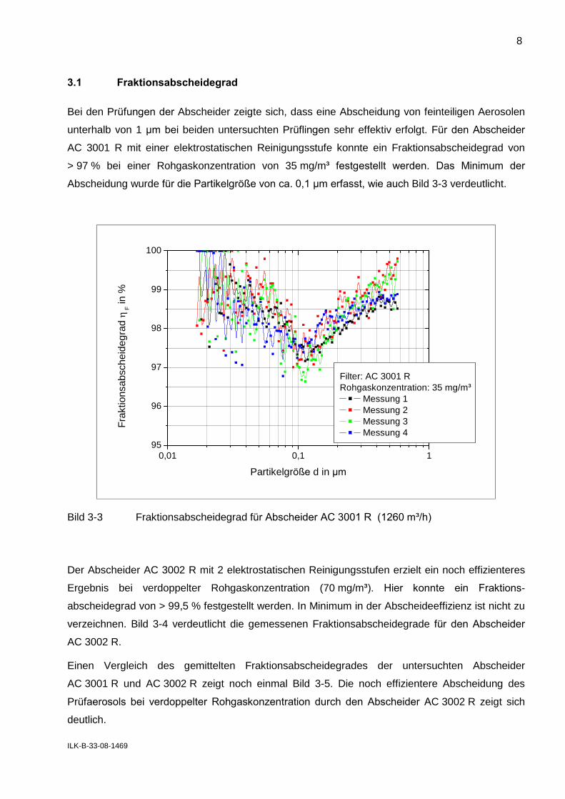
Bei den Prüfungen der Abscheider zeigte sich, dass eine Abscheidung von feinteiligen Aerosolen
unterhalb von 1 µm bei beiden untersuchten Prüflingen sehr effektiv erfolgt. Für den Abscheider
AC 3001 R mit einer elektrostatischen Reinigungsstufe konnte ein Fraktionsabscheidegrad von
> 97 % bei einer Rohgaskonzentration von 35 mg/m³ festgestellt werden. Das Minimum der
Abscheidung wurde für die Partikelgröße von ca. 0,1 µm erfasst, wie auch Bild 3-3 verdeutlicht.
0,01 0,1 195
96
97
98
99
100
Filter: AC 3001 RRohgaskonzentration: 35 mg/m³
Messung 1 Messung 2 Messung 3 Messung 4
Fra
ktio
nsab
sche
ideg
rad
F in
%
Partikelgröße d in µm
Bild 3-3 Fraktionsabscheidegrad für Abscheider AC 3001 R (1260 m³/h)
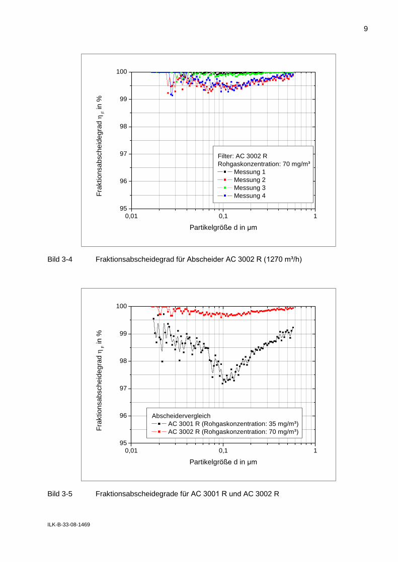
Der Abscheider AC 3002 R mit 2 elektrostatischen Reinigungsstufen erzielt ein noch effizienteres
Ergebnis bei verdoppelter Rohgaskonzentration (70 mg/m³). Hier konnte ein Fraktions-
abscheidegrad von > 99,5 % festgestellt werden. In Minimum in der Abscheideeffizienz ist nicht zu
verzeichnen. Bild 3-4 verdeutlicht die gemessenen Fraktionsabscheidegrade für den Abscheider
AC 3002 R.
Einen Vergleich des gemittelten Fraktionsabscheidegrades der untersuchten Abscheider
AC 3001 R und AC 3002 R zeigt noch einmal Bild 3-5. Die noch effizientere Abscheidung des
Prüfaerosols bei verdoppelter Rohgaskonzentration durch den Abscheider AC 3002 R zeigt sich
deutlich.
9
ILK-B-33-08-1469
0,01 0,1 195
96
97
98
99
100
Filter: AC 3002 RRohgaskonzentration: 70 mg/m³
Messung 1 Messung 2 Messung 3 Messung 4F
rakt
ions
absc
heid
egra
d
F in
%
Partikelgröße d in µm
Bild 3-4 Fraktionsabscheidegrad für Abscheider AC 3002 R (1270 m³/h)
0,01 0,1 195
96
97
98
99
100
Abscheidervergleich AC 3001 R (Rohgaskonzentration: 35 mg/m³)
AC 3002 R (Rohgaskonzentration: 70 mg/m³)
Fra
ktio
nsab
sche
ideg
rad
F in
%
Partikelgröße d in µm
Bild 3-5 Fraktionsabscheidegrade für AC 3001 R und AC 3002 R
10
ILK-B-33-08-1469
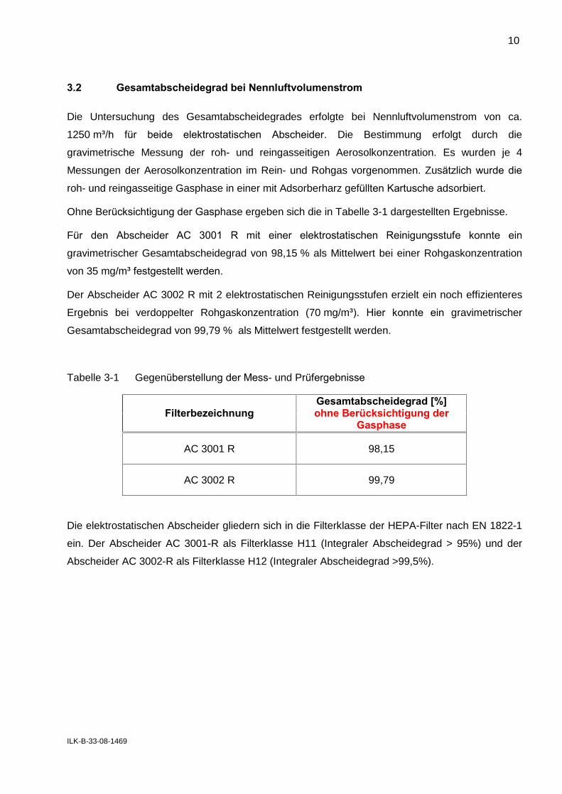
3.2 Gesamtabscheidegrad bei Nennluftvolumenstrom
Die Untersuchung des Gesamtabscheidegrades erfolgte bei Nennluftvolumenstrom von ca.
1250 m³/h für beide elektrostatischen Abscheider. Die Bestimmung erfolgt durch die
gravimetrische Messung der roh- und reingasseitigen Aerosolkonzentration. Es wurden je 4
Messungen der Aerosolkonzentration im Rein- und Rohgas vorgenommen. Zusätzlich wurde die
roh- und reingasseitige Gasphase in einer mit Adsorberharz gefüllten Kartusche adsorbiert.
Ohne Berücksichtigung der Gasphase ergeben sich die in Tabelle 3-1 dargestellten Ergebnisse.
Für den Abscheider AC 3001 R mit einer elektrostatischen Reinigungsstufe konnte ein
gravimetrischer Gesamtabscheidegrad von 98,15 % als Mittelwert bei einer Rohgaskonzentration
von 35 mg/m³ festgestellt werden.
Der Abscheider AC 3002 R mit 2 elektrostatischen Reinigungsstufen erzielt ein noch effizienteres
Ergebnis bei verdoppelter Rohgaskonzentration (70 mg/m³). Hier konnte ein gravimetrischer
Gesamtabscheidegrad von 99,79 % als Mittelwert festgestellt werden.
Tabelle 3-1 Gegenüberstellung der Mess- und Prüfergebnisse
Filterbezeichnung
Gesamtabscheidegrad [%]
ohne Berücksichtigung der
Gasphase
AC 3001 R 98,15
AC 3002 R 99,79
Die elektrostatischen Abscheider gliedern sich in die Filterklasse der HEPA-Filter nach EN 1822-1
ein. Der Abscheider AC 3001-R als Filterklasse H11 (Integraler Abscheidegrad > 95%) und der
Abscheider AC 3002-R als Filterklasse H12 (Integraler Abscheidegrad >99,5%).
11
ILK-B-33-08-1469
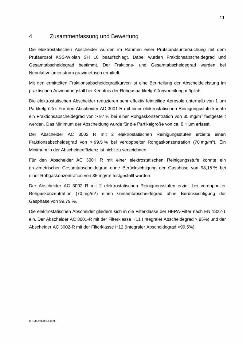
4 Zusammenfassung und Bewertung
Die elektrostatischen Abscheider wurden im Rahmen einer Prüfstandsuntersuchung mit dem
Prüfaerosol KSS-Wiolan SH 10 beaufschlagt. Dabei wurden Fraktionsabscheidegrad und
Gesamtabscheidegrad bestimmt. Der Fraktions- und Gesamtabscheidegrad wurden bei
Nennluftvolumenstrom gravimetrisch ermittelt.
Mit den ermittelten Fraktionsabscheidegradkurven ist eine Beurteilung der Abscheideleistung im
praktischen Anwendungsfall bei Kenntnis der Rohgaspartikelgrößenverteilung möglich.
Die elektrostatischen Abscheider reduzieren sehr effektiv feinteilige Aerosole unterhalb von 1 µm
Partikelgröße. Für den Abscheider AC 3001 R mit einer elektrostatischen Reinigungsstufe konnte
ein Fraktionsabscheidegrad von > 97 % bei einer Rohgaskonzentration von 35 mg/m³ festgestellt
werden. Das Minimum der Abscheidung wurde für die Partikelgröße von ca. 0,1 µm erfasst.
Der Abscheider AC 3002 R mit 2 elektrostatischen Reinigungsstufen erzielte einen
Fraktionsabscheidegrad von > 99,5 % bei verdoppelter Rohgaskonzentration (70 mg/m³). Ein
Minimum in der Abscheideeffizienz ist nicht zu verzeichnen.
Für den Abscheider AC 3001 R mit einer elektrostatischen Reinigungsstufe konnte ein
gravimetrischer Gesamtabscheidegrad ohne Berücksichtigung der Gasphase von 98,15 % bei
einer Rohgaskonzentration von 35 mg/m³ festgestellt werden.
Der Abscheider AC 3002 R mit 2 elektrostatischen Reinigungsstufen erzielt bei verdoppelter
Rohgaskonzentration (70 mg/m³) einen Gesamtabscheidegrad ohne Berücksichtigung der
Gasphase von 99,79 %.
Die elektrostatischen Abscheider gliedern sich in die Filterklasse der HEPA-Filter nach EN 1822-1
ein. Der Abscheider AC 3001-R mit der Filterklasse H11 (Integraler Abscheidegrad > 95%) und der
Abscheider AC 3002-R mit der Filterklasse H12 (Integraler Abscheidegrad >99,5%).
Institut für Luft- und Kältetechnik gGmbH Bereich Luftreinhaltung Bertolt- Brecht- Allee 20 01309 Dresden
Telefon 0351-4081-720 Fax 0351-4081-725
ILK-B-33-08-1469
Bericht über Abscheideleistung und Fraktionsabscheidegrad
Meßprotokoll ILK-B-33-08-1469/01
13.10.2008
Seitenzahl 2
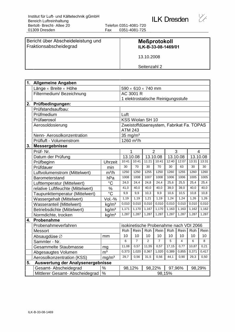
1. Allgemeine Angaben Länge Breite Höhe 590 610 740 mm Filtermedium/ Bezeichnung AC 3001 R
1 elektrostatische Reinigungsstufe 2. Prüfbedingungen: Prüfstandsaufbau: Prüfmedium Luft Prüfaerosol KSS Wiolan SH 10 Aerosoldosierung
Zweistoffdüsensystem, Fabrikat Fa. TOPAS ATM 243
Nenn- Aerosolkonzentration 35 mg/m³ Prüfluft - Volumenstrom 1260 m³/h 3. Messergebnisse Prüf- Nr. 1 2 3 4 Datum der Prüfung 13.10.08 13.10.08 13.10.08 13.10.08 Prüfbeginn Uhrzeit 10:41 10:41 11:21 10:41 12:40 12:07 13:31 13:31
Prüfdauer min 30 70 30 70 30 63 30 30
Luftvolumenstrom (Mittelwert) m³/h 1250 1250 1255 1250 1260 1255 1260 1260
Barometerstand hPa 1008 1008 1007 1008 1006 1006 1005 1005
Lufttemperatur (Mittelwert) °C 24,0 24,4 24,8 24,4 25,6 25,5 25,4 25,4
relative Luftfeuchte (Mittelwert) % 41,0 40,0 40,0 40,0 39,0 39,0 40,0 40,0
Taupunkttemperatur (Mittelwert) °C 9,9 9,9 10,3 9,9 10,6 10,5 10,8 10,8
Wassergehalt (Mittelwert) Vol.-% 1,19 1,19 1,21 1,19 1,24 1,24 1,26 1,26
Wasseranteil (Mittelwert) kg/m³ 0,010 0,010 0,010 0,010 0,010 0,010 0,010 0,010
Betriebsdichte (Mittelwert) kg/m³ 1,171 1,170 1,167 1,170 1,163 1,163 1,162 1,162
Normdichte, trocken kg/m³ 1,287 1,287 1,287 1,287 1,287 1,287 1,287 1,287
4. Probenahme Probenahmeverfahren isokinetische Probenahme nach VDI 2066 Messort Roh Rein Roh Rein Roh Rein Roh Rein
Absaugdüse mm 10 10 10 10 10 10 10 10
Sammler - Nr. 6 7 2 7 5 4 6 8
Gesammelte Staubmasse mg 11,08 0,57 11,55 0,57 17,15 0,77 10,87 0,21
Abgesaugtes Volumen m³ 0,373 1,020 0,367 1,020 0,389 0,855 0,371 0,417
Aerosolkonzentration (KSS) mg/m³ 29,7 0,56 31,5 0,56 44,1 0,90 29,3 0,50
5. Auswertung der Analysenergebnisse Gesamt- Abscheidegrad % 98,12% 98,22% 97,96% 98,29% Mittlerer Gesamt- Abscheidegrad % 98,15%
Institut für Luft- und Kältetechnik gGmbH Bereich Luftreinhaltung Bertolt- Brecht- Allee 20 01309 Dresden
Telefon 0351-4081-720 Fax 0351-4081-725
ILK-B-33-08-1469
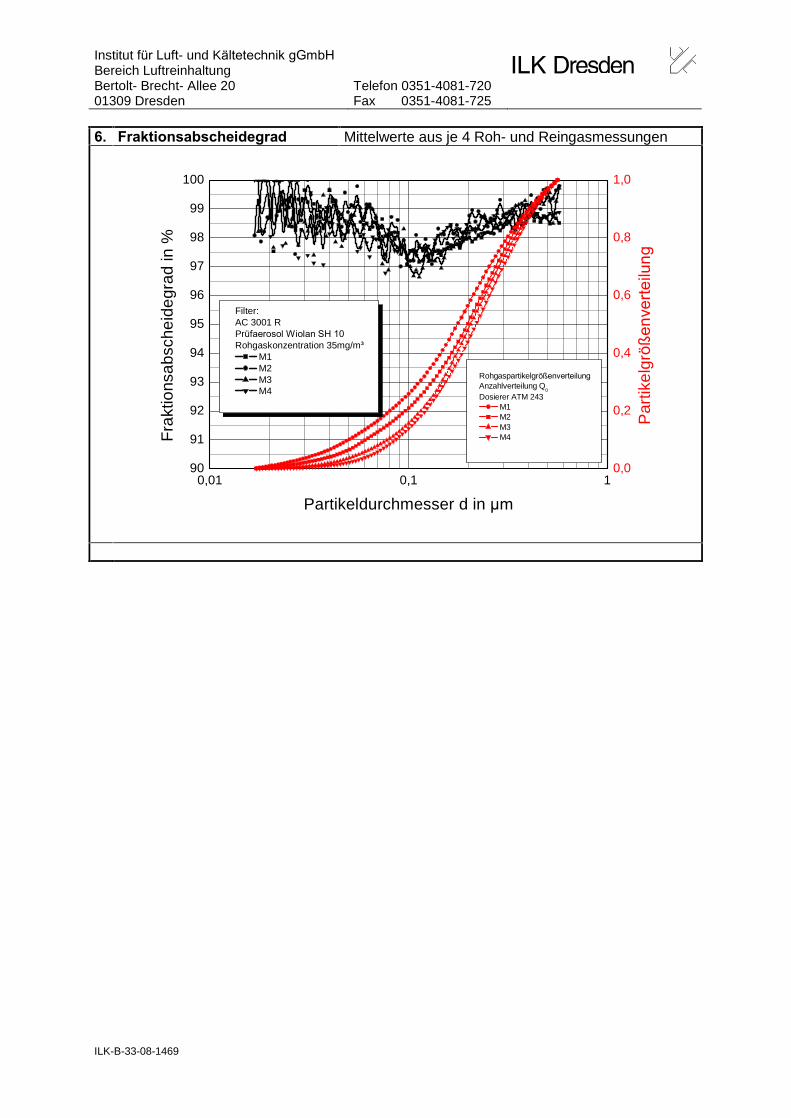
6. Fraktionsabscheidegrad Mittelwerte aus je 4 Roh- und Reingasmessungen
0,01 0,1 190
91
92
93
94
95
96
97
98
99
100
Filter: AC 3001 RPrüfaerosol Wiolan SH 10
Rohgaskonzentration 35mg/m³
M1 M2 M3 M4
Fra
ktio
nsab
sche
ideg
rad
in %
Partikeldurchmesser d in µm
0,0
0,2
0,4
0,6
0,8
1,0
Par
tikel
grö
ße
nve
rte
ilu
ng
Rohgaspartikelgrößenverteilung
Anzahlverteilung Q0
Dosierer ATM 243 M1 M2 M3 M4
Institut für Luft- und Kältetechnik gGmbH Bereich Luftreinhaltung Bertolt- Brecht- Allee 20 01309 Dresden
Telefon 0351-4081-720 Fax 0351-4081-725
ILK-B-33-08-1469
Bericht über Abscheideleistung und Fraktionsabscheidegrad
Meßprotokoll ILK-B-33-08-1469/02
13.10.2008
Seitenzahl 2
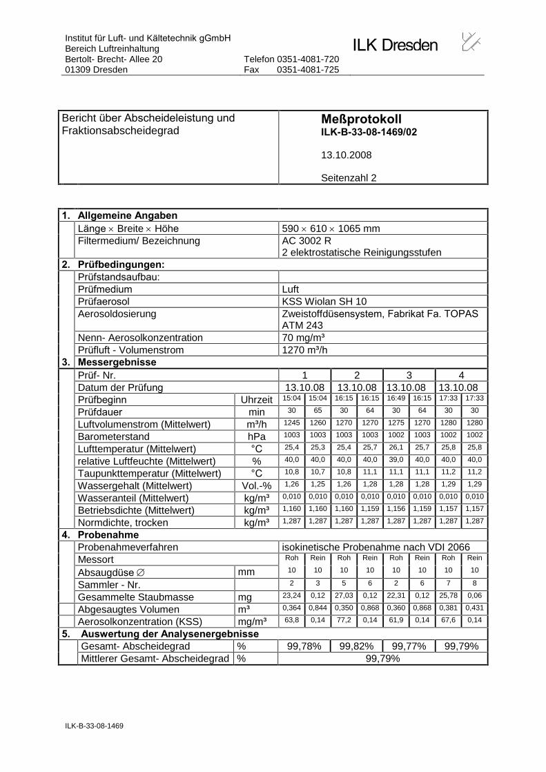
1. Allgemeine Angaben Länge Breite Höhe 590 610 1065 mm Filtermedium/ Bezeichnung AC 3002 R
2 elektrostatische Reinigungsstufen 2. Prüfbedingungen: Prüfstandsaufbau: Prüfmedium Luft Prüfaerosol KSS Wiolan SH 10 Aerosoldosierung
Zweistoffdüsensystem, Fabrikat Fa. TOPAS ATM 243
Nenn- Aerosolkonzentration 70 mg/m³ Prüfluft - Volumenstrom 1270 m³/h 3. Messergebnisse Prüf- Nr. 1 2 3 4 Datum der Prüfung 13.10.08 13.10.08 13.10.08 13.10.08 Prüfbeginn Uhrzeit 15:04 15:04 16:15 16:15 16:49 16:15 17:33 17:33
Prüfdauer min 30 65 30 64 30 64 30 30
Luftvolumenstrom (Mittelwert) m³/h 1245 1260 1270 1270 1275 1270 1280 1280
Barometerstand hPa 1003 1003 1003 1003 1002 1003 1002 1002
Lufttemperatur (Mittelwert) °C 25,4 25,3 25,4 25,7 26,1 25,7 25,8 25,8
relative Luftfeuchte (Mittelwert) % 40,0 40,0 40,0 40,0 39,0 40,0 40,0 40,0
Taupunkttemperatur (Mittelwert) °C 10,8 10,7 10,8 11,1 11,1 11,1 11,2 11,2
Wassergehalt (Mittelwert) Vol.-% 1,26 1,25 1,26 1,28 1,28 1,28 1,29 1,29
Wasseranteil (Mittelwert) kg/m³ 0,010 0,010 0,010 0,010 0,010 0,010 0,010 0,010
Betriebsdichte (Mittelwert) kg/m³ 1,160 1,160 1,160 1,159 1,156 1,159 1,157 1,157
Normdichte, trocken kg/m³ 1,287 1,287 1,287 1,287 1,287 1,287 1,287 1,287
4. Probenahme Probenahmeverfahren isokinetische Probenahme nach VDI 2066 Messort Roh Rein Roh Rein Roh Rein Roh Rein
Absaugdüse mm 10 10 10 10 10 10 10 10
Sammler - Nr. 2 3 5 6 2 6 7 8
Gesammelte Staubmasse mg 23,24 0,12 27,03 0,12 22,31 0,12 25,78 0,06
Abgesaugtes Volumen m³ 0,364 0,844 0,350 0,868 0,360 0,868 0,381 0,431
Aerosolkonzentration (KSS) mg/m³ 63,8 0,14 77,2 0,14 61,9 0,14 67,6 0,14
5. Auswertung der Analysenergebnisse Gesamt- Abscheidegrad % 99,78% 99,82% 99,77% 99,79% Mittlerer Gesamt- Abscheidegrad % 99,79%

Institut für Luft- und Kältetechnik gGmbH Bereich Luftreinhaltung Bertolt- Brecht- Allee 20 01309 Dresden
Telefon 0351-4081-720 Fax 0351-4081-725
ILK-B-33-08-1469
6. Fraktionsabscheidegrad Mittelwerte aus je 4 Roh- und Reingasmessungen
0,01 0,1 190
91
92
93
94
95
96
97
98
99
100
Filter: AC 3002 RPrüfaerosol Wiolan SH 10
Rohgaskonzentration 70 mg/m³
M1 M2 M3 M4
Fra
ktio
nsab
sche
ideg
rad
in %
Partikeldurchmesser d in µm
0,0
0,2
0,4
0,6
0,8
1,0
Par
tikel
grö
ße
nve
rte
ilu
ng
Rohgaspartikelgrößenverteilung
Anzahlverteilung Q0
Dosierer ATM 243 M1 M2 M3 M4


