Simulation of fluid-structure interaction for an elastic cylinder in an axial flow
Z. G. Liu1, Y. Liu1 & J. Lu2
1Department of Mechanical Engineering, Hong Kong Polytechnic University, China 2College of Engineering, City University of Hong Kong, China
Abstract
The fluid-structure interaction for an elastic cylinder in an axial flow was studied numerically with the ALE method and the LES turbulence model. The commercial CFD software Fluent is used as the fluid solver and the Euler-Bernoulli beam solver is embedded into Fluent by its user defined functions (UDF). Two types of cylinder are included in this study. The motion for the first type of cylinder is constrained in one lateral direction and for the second in two lateral directions. The two types of cylinder are both released from their equilibrium state. When the stiffness is kept large enough, only weak oscillatory is induced by the flow. However, the motion of the cylinder induced by the flow may become unstable in the form of either buckling or oscillatory, when the stiffness becomes small enough. In this study, it is found that with the same simulation parameters the first type of cylinder is buckled and the second has an oscillatory. When buckled, the cylinder is located at a new state with weak oscillatory. The oscillatory after the instability has much larger amplitude than that before the instability. Keywords: CFD, fluid-structure interaction, fluidelastic instability, buckling, flutter.
1 Introduction
One of the most classical subjects in fluid mechanics is the flow over cylinder, by which many interesting and significant phenomena are discovered such as Karman vortex streets [1] and also by which, for example, one can get the Kutta-Joukowski theorem, one of the most basic theorems in aerodynamics [2].
However, this is almost for a rigid cylinder and the flow past a deformable cylinder attracts more and more interest of researchers due to not only its academic importance but also a lot of applications in engineering such as nuclear station design, building and so on. In this case, the fluid-structure interaction (FSI) will arise. FSI is a big topic and includes many aspects, nevertheless in this paper we just focus on a slender deformable cylinder subjected to axial flow. This problem has been studied by many researchers and a good recent review was conducted by Wang and Ni in [3], where they also reviewed other FSI systems besides the system in this paper. In 1966, Paidoussis [4] developed a theory to deal with the dynamics for a single cylinder subjected to axial flow based on the Lighthill theory [5], which was used to get the force related to added mass, and Taylor’s theory [6], which was applied to calculate viscous force imposed on the cylinder. The two kinds of force related to fluid flow and other kinds of force all were imposed on the cylinder regarded as an Euler-Bernoulli beam in his theory [4]. Based on his theory, Paidoussis [4] concluded that the stability of the system is determined partly by the dimensionless velocity, the definition of which will be written in the following, i.e. the flow damps the vibration for small dimensionless velocity while the cylinder may become instable, either in the form of buckling or flutter, when this parameter becomes large enough. He also conducted experiment to check his theory [7]. Taking gravity into account and modifying frictional force, Paidoussis also developed his theory further [8], however still a linear theory, which was mended further by Lopes et al. [9] into a nonlinear one for cantilevered cylinder in axial flow. The basic conclusion based on this nonlinear theory and that based on the linear theory have no crucial differences [10, 11]. In addition, the idea of Paidoussis’s deriving his theory can be extended to several cylinders subjected to axial flow [12–14]. When the flow velocity is small, the cylinder could vibrate but with small amplitude. This kind of vibration, often called sub-critical vibration, is related to the perturbation of flow field [15, 16]. Some former researchers used semi-empirical methods to predict the amplitude of this kind of vibration [17–19]. But one must have the loading distribution available from experiments in order to adopt those methods in practice. It is very manifest that one should consider both the fluid flow field and the structure dynamics when he deals with FSI. In some simple cases, one can get an analytic solution for the FSI system [20]. But unfortunately, on the other hand, in the most cases one can not get a fluid flow field solution to give enough information to the structure, even if the structure is not of complexity, e.g. the FSI system in this paper, a cylinder subjected to axial flow. Even in the theories mentioned above, the flow field is actually obtained based on some assumptions. Thus in this paper, we simulate numerically the FSI system shown in fig. 1, namely solve the fluid flow field in the arbitrary Lagrange-Euler (ALE) frame with CFD and the cylinder dynamics equation numerically. The paper is divided into four parts. The model and governing equations will be introduced in the
second part, followed is the third part, where the numerical details will be illuminated. In the last part, we will discuss the results and make a brief conclusion.
Figure 1: Schematic model.
2 Model and governing equations
The FSI system is shown in fig. 1, where D denotes the outer diameter of the cylinder. The cylinder clamped at its two ends, 20D long with its inner diameter 0.88D, is located in the fluid flow confined by a cylindrical pipe that is the same long as the cylinder with 4D diameter. The fluid could flow from one end to the other, inducing the vibration of the cylinder. In this paper, we study two cases for the model, in the first of which the cylinder is constrained only to vibrate in one lateral direction, while in the second of which the cylinder can vibrate in two lateral directions. For the different cases respectively, the same parameters are adopted in the simulation. The main parameters are listed in table 1, where the dimensionless velocity υ and the mass ratio β are defined by eqns. (7) in section 4. The Reynolds number Re is based on the hydraulic diameter, which is 3D, and the inlet flow velocity υ0.
Table 1: The parameters of calculation.
Case 1 2
Re 8×10⁴
υ 6.0173 8.8997 6.0173 8.8997
β 0.4699 0.4699 0.4699 0.4699
First, it should be noted that the fluid flow velocity here is small and there is no need to consider the compression of the fluid. Therefore the incompressible Navier-Stokes (N-S) equations are one of the bases. Generally speaking, the fluid domain deforms in the process of simulation due to the deformation of the interfaces between the fluid and structure domains. To take into account the deformation of the fluid domain essentially, one method for CFD is rewriting the N-S equations as arbitrary Lagrange-Euler form, i.e. ALE N-S equations [20, 21]:
where t, υ, p, ρ and μ are time, fluid velocity, pressure, density and viscosity respectively; υ
refers to mesh node velocity, which related to the deformation of
the fluid domain. One can find the detailed derivation in [20]. In eqns. (1), the flow variables are solved in Euler frame as usual while the mesh nodes are regarded in Lagrange frame. This is why eqns. (1) are called ALE N-S equations. It is easily seen that eqns. (1) become the common N-S equations if the mesh node velocity 0υ . The large eddy simulation (LES) model [22, 23] is adopted to deal with the turbulence and the Smagorinsky-Lilly model [22, 23] is utilized as the subgrid-scale model. The cylinder is considered as an Euler-Bernoulli beam and currently the axial loading and gravity are ignored here. The coordinates system is shown in fig. 1 and right-hand. The dynamic equation is [24]
),(
4
4
2
2
tzqz
uEI
t
uAb
(2)
with u(z) being the displacement of cross sections in beam, EI, A, ρb being the modulus of flexural rigidity, cross-sectional area, density of the beam, respectively, q(z, t) being the loading on beam and calculated after the fluid field is solved. Eqn. (2) is just for the vibration of cylinder in one plane (for example x-z plane) and the dynamic equation for the other plane is ignored here, because they have the same form. Eqn. (2) can be solved numerically by finite element method (FEM), and the numerical details are explained in the following part. The boundary conditions at two ends of the cylinder are both clamped as mentioned above, which give
02/
2/2/
2/
Lz
LzLz
Lz z
uu
z
uu
(3)
with L = 20D being the length of the cylinder (see fig. 1). In addition, the mesh is remeshed at each simulating step by spring analogy
[23], in which the nodes of mesh are considered as being connected by fictitious springs whose stiffnesses are concerned with the locations of nodes. In this paper, the fictitious spring constant between two nodes is assumed being inverse proportion of their distance [23].
3 Numerical approach
The simulation on FSI actually needs to treat three distinct fields coupled together [25]. The first field is fluid flow field governed by N-S equations, the second is related to the structure deformation and the last one refers to the mesh
motion. These three coupled fields give rise to three equations sets still coupled together after discretization, making a great challenge for numerical simulation. In the past years, to overcome this challenge, many researchers [25–28] proposed many available numerical approaches, which, however generally speaking, can be classified roughly into two major categories, monolithic [26] and partitioned
[25, 27, 28]. The monolithic approaches do not uncouple three numerical equations sets and solve them simultaneously as one, while the partitioned approaches solve them in sequence. The monolithic approaches have better numerical stability [27] but cost more computational resources than the partitioned ones. In practice, one of major difficulties in adopting the monolithic approaches is that the programming codes for them should usually be rewritten and can not reuse efficiently the already existing CFD or structure solvers. Therefore, the partitioned approaches are still popular and applied in this study. The applied partitioned scheme is shown in fig. 2 and the same as CSS in [28]. The commercial software Fluent is utilized as the CFD solver, in which the ALE N-S equations are discretized by finite volume method (FVM) [23], and the structure codes by finite element method [29] based on eqns. (2) and (3) are embedded into the former by its providing user-defined functions (UDF) [23], some of which provide the access to controlling the motion of fluid domain mesh in simulation. The algorithm of updating mesh has been explained above and is implemented in Fluent. Firstly, the flow field is calculated by Fluent and sequentially obtained is the loading exerted on the cylinder (regarded as a beam), by which the structure codes determine the deformation of the cylinder, forming new boundary for the fluid domain. Then Fluent updates the mesh and a new cycle begins if needed. It should be noted that the fluid flow in all cases is simulated with turbulence model.
Figure 2: Simulation steps.
For the flow simulation, the first order implicit method for temporal discretization and the bounded central differencing scheme for spatial discretization are adopted with the PISO method for pressure-velocity coupling [23]. For turbulent flow, the LES model is utilized with Smagorinsky-Lilly as subgrid-scale model [22, 23].
Now, we focus on the discretization of eqn. (2). Through the standard Galerkin procedure of FEM [29], it with eqn. (3) can be discretized as one ordinary differential equations set
QKuuM (4)
where M and K are global mass and stiffness matrices respectively; T
N ],,,[ 21 uuuu , a function of time t and z, is generalized displacements
vector of N nodes including two end nodes. For one certain node, its generalized displacement consists of its displacement and rotation, i.e.
],[ iii v u (5)
with iv and i being displacement and rotation of th node, respectively.
and are assembled by local mass and stiffness matrices respectively. One can find the details on these local mass and stiffness matrices and how to assemble them to global ones as well as how to get i n [29 , 30] . Eqn . (4) is solved by the generalized-α method, an extension version of HHT-α and WBZ-α method, having the second-order accuracy and being unconditional stable if its parameters are set appropriately [31]. The loading here includes pressure and frictional force, the same as proposed by Paidoussis [4, 16] except the ignored axial force, i.e.
C jijiji dlnpq )( . (6)
where qi is the loading in eqn. (2) with i = x, y, τij is the deviatoric stress tensor and nj refers to the normal vector of the cylinder, and C is its lateral perimeter.
4 Results and discussion
For convenience, following Paidoussis [4, 16], we define dimensionless velocity υ, the mass ratio β, the dimensionless time τ and displacement by
EI
AL t
0 ,ebt
t
AA
A
,teb AA
EI
L
t
2,
D
zud x
x
)( ,
D
zud y
y
)( (7)
where υ0 and ρ are the flow inlet velocity and fluid density respectively; L, ρb, At, and Ae are respectively the length, density, total cross-sectional area and effective cross-sectional area of the cylinder; dx and dy are the dimensionless displacement in x direction and y direction respectively with ux and uy being the corresponding displacement. Note that Ae is actually A in eqn. (2) and different from At since the cylinder is hollow.
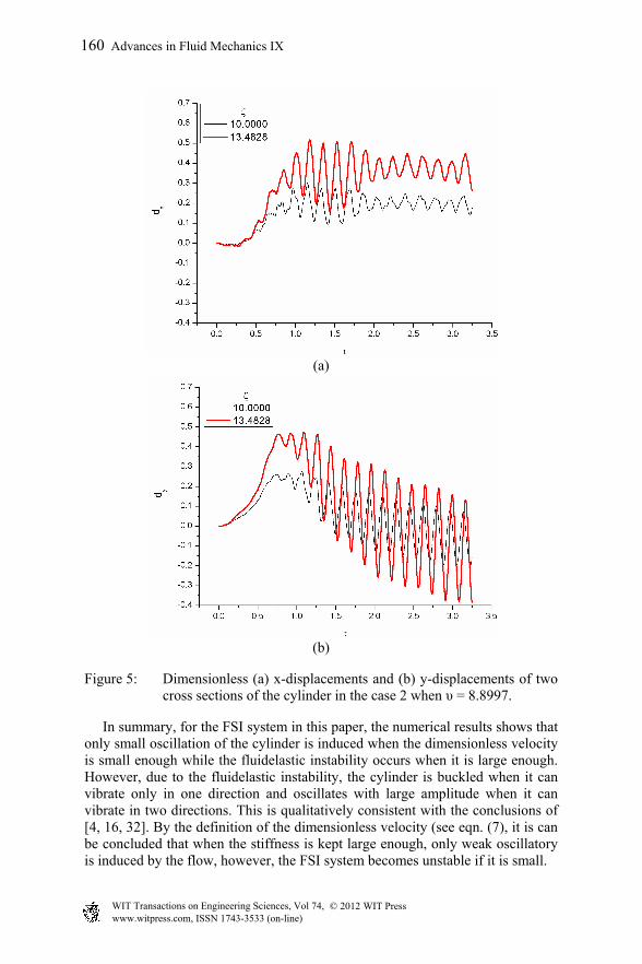
The simulation parameters are shown in table 1, in which case 1 is related to the case where only one direction vibration is calculated and case 2 to the other one where the vibrations in two directions are both calculated. For different cases, the cylinder is located initially at its equilibrium state and only induced by fluid flow to vibrate. By increasing or decreasing stiffness of the cylinder, we can make the dimensionless velocity smaller or lager and thus focus on the effect of the latter for generalizing, by which the effect of the former can be easily and clearly concluded. In this paper, the effect of β is not discussed. Fig. 3 shows the displacement histories of two cross sections of the cylinder in x direction for the case 1, where ζ is dimensionless length based on the diameter of the cylinder and ζ = 0, 20 means two ends of the cylinder respectively. These two cross sections have the almost most maximum displacement and thus the following results also focus on them. It can be found from fig. 3 (a) that the oscillation amplitudes are small, about maximum 0.01D with D diameter of the cylinder, when the dimensionless velocity υ equals 6.0173. This kind of oscillation is almost around the initial equilibrium position of the cylinder and attributed to the turbulence as we mentioned above and called sub-critical vibration. However, when υ is increased to 8.8997, or equivalently the stiffness of the cylinder is decreased, as shown in fig. 3 (b) one dramatic vibration is induced distinct from that shown in fig. 3 (a). At the beginning, the oscillations with small amplitudes are induced till τ = 1.0 as they are when υ = 6.0173, after which the displacements rapidly increase to a large value about maximum 0.6D within a short time and then will never do visibly. Consequently, the cylinder oscillates around a new position with an approximate maximum amplitude 0.025D lager than that when υ = 6.0173. It indicates that the cylinder is buckled at a new position. This phenomenon is one type of fluidelastic instability and in particular discussed for the cylinder subjected to axial flow by Paidoussis [4, 7, 16]. We now move on to the case 2, where the cylinder can vibrate in two directions. Fig. 4 shows the vibrations of two same selected cross sections in two directions when υ = 6.0173. The oscillating amplitudes in two directions are also small, about maximum 0.05D in x direction and 0.03D in y direction. No matter in x and y directions, the oscillating is almost around the initial equilibrium position of the cylinder. This is similar to that shown in fig. 3 (a) and also this oscillation should be related to the turbulence. Nevertheless, when υ = 8.8997, the difference between case 1 and case 2 is apparent. Fig. 5 shows the vibrations in two directions when υ = 8.8997. Initially, the cylinder vibrates around its equilibrium position and then deviates rapidly from this position. The deviation is followed by an oscillation with the amplitude approximately maximum 0.1D in x direction and 0.2D in y direction both much larger than that after rapid increasing of the displacement shown in fig. 3 (b). This oscillation is different from the initial oscillation that should be only about 10-3 to 10-2D [16] and thus could not be mainly associated with the turbulence but due to another kind of fluidelastic instability called flutter. Comparing fig. 3 (b) and fig. 5, one can further find that the time of the displacement rapidly increasing onset in the former is after that in the latter, together with the fact that the buckling usually
occurs at a smaller value of the dimensionless velocity than the flutter [4, 16] concluding that the FSI system here is more stable when the cylinder is constrained only to vibrate in one direction than when it can vibrate in two directions.
(a)
(b)
Figure 3: Dimensionless x-displacements of two cross sections of the cylinder in the case 1 when (a) υ = 6.0173 and (b) υ = 8.8997.
The buckling is not predicted by Paidoussis theory [4] for his considering a specific model similar to the model in this paper, but by recent nonlinear theory [32], the buckling is possible for a similar clamped-clamped system. The value 8.8997 of the dimensionless velocity for buckling (in case 1) or flutter (in case 2) is different from that of fluidelastic instability onset suggested by Modarres-
Sadeghi et π for buckling and 21.6 for flutter. It should be noted that the numerical method in this paper is much difficultly applied to predict the value of the dimensionless velocity after which the fluidelastic instability occurs, since it is impossible to simulate sufficient cases for different dimensionless velocities due to long time cost in numerical simulation. The value 8.8997 may not be one of fluidelastic instability onsets for the FSI system in this paper. Another reason for this difference should be attributed to the difference between the FSI systems in this paper and [32]. However, the results here are qualitatively consistent with those in [4, 16, 32].
(a)
(b)
Figure 4: Dimensionless (a) x-displacements and (b) y-displacements of two cross sections of the cylinder in the case 2 when υ = 6.0173.
Figure 5: Dimensionless (a) x-displacements and (b) y-displacements of two cross sections of the cylinder in the case 2 when υ = 8.8997.
In summary, for the FSI system in this paper, the numerical results shows that only small oscillation of the cylinder is induced when the dimensionless velocity is small enough while the fluidelastic instability occurs when it is large enough. However, due to the fluidelastic instability, the cylinder is buckled when it can vibrate only in one direction and oscillates with large amplitude when it can vibrate in two directions. This is qualitatively consistent with the conclusions of [4, 16, 32]. By the definition of the dimensionless velocity (see eqn. (7), it is can be concluded that when the stiffness is kept large enough, only weak oscillatory is induced by the flow, however, the FSI system becomes unstable if it is small.
Support given by the HKPolyU/AREVA collaboration under grant No.RPQ4 is gratefully acknowledged.
References
[1] White F.M., Viscous Fluid Flow, McGraw-Hill: New York, pp. 4-15, 2006. [2] Anderson J.D., Fundamentals of Aerodynamics. McGraw-Hill: New York,
pp. 232-239, 2001. [3] Wang L. and Ni Q., Vibration of Slender Structures Subjected to Axial
Flow or Axially Towed in Quiescent Fluid. Advances in Acoustics and Vibration, 2009, pp. 1-19, 2009.
[4] Paidoussis M.P., Dynamics of Flexible Slender Cylinders in Axial Flow, part 1: theory. Journal of Fluid Mechanics, 26, pp. 717-736, 1966.
[5] Lighthill M.J., Note on the Swimming of Slender Fish. Journal of Fluid Mechanics, 9, pp. 305-317, 1960.
[6] Taylor G., Analysis of the Swimming of Long and Narrow Animals. Proceedings of the Royal Society of London, Series A, Mathematical and Physical Science, 214, pp. 158-183, 1952.
[7] Paidoussis M.P., Dynamics of Flexible Slender Cylinders in Axial Flow, part 2: experiments. Journal of Fluid Mechanics, 26, pp. 737-751, 1966.
[8] Paidoussis M.P., Dynamics of Cylindrical Structures Subjected to Axial Flow. Journal of Sound and Vibration, 29, pp. 365-385, 1973.
[9] Lopes J.L., Paidoussis M.P. and Semler C., Linear and Nonlinear Dynamic of Cantilevered Cylinders in Axial Flow, part 2: The Equation of Motion. Journal of Fluids Structures, 16, pp. 715-737, 2002.
[10] Paidoussis M.P., Grinevich E., Anamovic D. and Semler C., Linear and Nonlinear Dynamic of Cantilevered Cylinders in Axial Flow, part 1: Physical Dynamics. Journal of Fluids Structures, 16, pp. 691-713, 2002.
[11] Semler C., Lopes J.L., Augu N. and Paidoussis M.P., Nonlinear Dynamic of Cantilevered Cylinders in axial flow, part 3: Nonlinear Dynamics. Journal of Fluids Structures, 16, pp. 739-759, 2002.
[12] Chen S.S., Vibration of Nuclear Fuel Bundles. Nuclear Engineering and Design, 35, pp. 399-422, 1975.
[13] Paidoussis M.P. and Suss S., Stability of a Cluster of Flexible Cylinders in Bounded Axial Flow. Journal of Applied Mechanics, 44, pp. 401-408, 1977.
[14] Paidoussis M.P., The Dynamics of Clusters of Flexible Cylinders in Axial Flow: Theory and Experiments. Journal of Sound and Vibrations, 65, pp. 391-417, 1979.
[15] Paidoussis M.P. and Curling L.R., An Analytical Model for Vibration of Clusters of Flexible Cylinders in Turbulent Axial Flow. Journal of Sound and Vibrations, 98, pp. 493-517, 1985.
[16] Paidoussis M.P., Fluid-Structure Interactions: Slender Structure and Axial Flow, Vol. 2, Elsevier: London and California, pp. 787-877, 2004.
[17] Reavis J.R., Vibration Correlation for Maximum Fuel-Element Displacement in Parallel Turbulent Flow. Nuclear Science and Engineering, 38, pp.63-69, 1969.
[18] Reavis J.R., WVI-Westinghouse Vibration Correlation for Maximum Fuel-Element Displacement in Parallel Turbulent Flow. Transactions of the American Nuclear Society, 10, pp. 369-371, 1967.
[19] Gorman D.J., An Analytical and Experimental Investigation of the Vibration of Cylindrical Reactor Fuel Elements in Two-Phase Parallel Flow. Nuclear Science and Engineering, 44, pp. 277-290, 1971.
[20] Wang X.D., Fluid-Solid Interactions: Analytical and Computational Approaches, Elsevier: Amsterdam and Oxford, pp. 163-169, 2008.
[21] Stein E., De Borst R. and Hughes J.R., (eds). Encyclopedia of Com-putational Mechanics, Vol. 1 (Chapter 14). Arbitrary Lagrangian-Eulerian Methods, ed. Donea J. etc, John Wiley and Sons, Ltd., pp. 1-25, 2004.
[22] John V., Large Eddy Simulation of Turbulent Incompressible Flows. Springer-Verlag: Berlin and Heidelberg, pp. 21-62, 2004.
Company, Inc.: Reading and Massachusetts, pp. 204-208, 1966. [25] Piperno S., Farhat C. and Larrouturou B., Partitioned procedures for the
transient solution of coupled aeroelastic problems, part 1: Model problem, theory and two-dimensional application. Computer Methods in Applied Mechanics and Engineering, 124, pp. 79-112, 1995.
[26] Blom F.J., A monolithical fluid-structure interaction algorithm applied to the piston problem. Computer Methods in Applied Mechanics and Engineering, 167, pp. 369-391, 1998.
[27] Matthies H.G. and Steindorf J., Partitioned but strongly coupled iteration schemes for nonlinear fluid-structure interaction. Computers and Structures, 80, pp. 1991-1999, 2002.
[28] Farhat C. and Lesoinne M., Two Efficient Staggered Algorithms for the Serial and Parallel Solution of Three-Dimensional Nonlinear Transient Aeroelastic Problems. Computer Methods in Applied Mechanics and Engineering, 182, pp. 499-515, 2000.
[29] Zienkiewicz O.C., Taylor R.L. and Zhu J.Z., The Finite Element Method: Its Basis and Fundamentals. Elsevier Butterworth-Heinemann: Oxford and New York, pp. 54-95, 2005.
[30] Zienkiewicz O.C. and Taylor R.L., The Finite Element Method for Solid and Structural Mechanics. Elsevier Butterworth-Heinemann: Oxford and New York, pp. 278-320, 2005.
[31] Chung J. and Hulbert G.M., A Time Integration Algorithm for Structural Dynamics with Improved Numerical Dissipation: The Generalized-α Method. Journal of Applied Mechanics, 60, pp. 371-375, 1993.
[32] Modarres-Sadeghi Y., Paidoussis M.P. and Semler C., The Nonlinear Behavior of a Slender Flexible Cylinder Pinned or Clamped at Both Ends and Subjected to Axial Flow. Computers and Structures, 85, pp. 1121-1133, 2007.