+ All Categories
Home > Documents > SINGLE EVENT UPSETS ON STATIC RANDOM BY SOUAAD BEN …

SINGLE EVENT UPSETS ON STATIC RANDOM BY SOUAAD BEN …

Date post: 08-Apr-2022
Category:
Upload: others
View: 4 times
Download: 0 times
Share this document with a friend
24
SINGLE EVENT UPSETS ON STATIC RANDOM ACCESS MEMORY BY SPENVIS AND PSPICE SIMULATION AT NEAR EQUATORIAL ORBITS BY SOUAAD BEN KARA MAHAMMED A dissertation submitted in fulfilment of the requirement for the degree of Master of Science (Electronics Engineering) Kulliyyah of Engineering International Islamic University Malaysia AUGUST 2016
Transcript

SINGLE EVENT UPSETS ON STATIC RANDOM

ACCESS MEMORY BY SPENVIS AND PSPICE

SIMULATION AT NEAR EQUATORIAL ORBITS

BY

SOUAAD BEN KARA MAHAMMED

A dissertation submitted in fulfilment of the requirement for

the degree of Master of Science (Electronics Engineering)

Kulliyyah of Engineering

International Islamic University Malaysia

AUGUST 2016

ii

ABSTRACT

Memories, such as Static Random Access Memories (SRAMs) are important parts in

microelectronic circuits. SRAM is used to store data in a circuit. In harsh space

environments with high energetic radiation, SRAM devices are likely to interact with

ionizing electrons, protons and various ions. This interaction induces excess charge

within the device that modifies its electronic state, causing various types of unwanted

effects including Single Event Upset (SEU). This work computes the critical charge

(Qcrit) that is required to upset 90nm and 180nm CMOS 6T SRAM cells at their two

most sensitive nodes at Q and Qbar. Different current values are used with a supplied

voltage ranging from 0.2 V to 1V. Based on the obtained critical charge, the single

event upset rates are reported as a function of radiation particles, shielding and

striking nodes (transistor drain) size. This investigation is performed by simulation

devices in Near Equatorial Orbit (NEqO) environment, using ORCAD PSPICE and

SPENVIS simulation tools. The results show that Q node is more vulnerable to SEU

than Q bar node for both technologies similarly. 90nm SRAM is more susceptible to

SEU than 180nm. It is also found that shielding by 0.5 mg/cm2 Al has no effect on

Galactic Cosmic Rays(GCR) radiation. Solar particles (SP) dominates the effect rates,

however trapped particles (TP) have the least effects. Drainlength plays an important

role in the SEU rates variation. It may minimize the upset rates with small drain length

and low supplied voltage. Shielding by 0.5 g/cm2 of Al and decreasing the drain

length can mitigate the transistor susceptibility to SEU. Thus, it can be justified that

smaller CMOS transistor technology has high potential to be used in space.

iii

خلاصة البحثABSTRACT IN ARABIC

تشكل جزءا هاما في الدارات الميكروالكترونية ( SRAMs) ذاكرة الوصول العشوائي الثابتةخلايا الذاكرة ، كــ اجهزة الذاكرة الحديثة. في الفضاء، بوجود محيط قاس بسبب النشاط الإشعاعي العالي، فانه من الممكن أن تتفاعل

SRAM مع الإلكترونات والبروتونات المؤينة و مختلف الأيوناتالاخرى. هذا التفاعل يحث على انتاج فائض فيالشحنة داخل الجهاز والذي يؤدي الى تغيير حالته الالكترونية مما يسبب أنواع مختلفة من الآثار المزعجة على غرار

( المطلوبة لاضطراب كل من Qcritالحرجة )هذا العمل يحسب كمية الشحنة (.SEU)حادثة أحادي الاضطراب عقدتين الأكثر عند ال 90nm CMOS 6Tو SRAM :180 nm CMOS 6Tخلايا الذاكرة

على قيم الشحنة ا. وبناء1Vإلى V 0.2مورد بتغير من تيار حساسية لديهما. قيم مختلفة للتيار قد استعملت مع الجسيمات الإشعاعية ، التغليف قد تم تقريرها وبدلالة SEUلـــ ( التي تم الحصول عليها، معدلات اQcritالحرجة )

(، وبتتطبيق NEqOوحجم العقدة المصدومة. هذا البحث تم تنفيذه في محيط المدارات الاستوائية الدنى )PSPICE ORCAD وأدوات المحاكيSPENVIS وقد أظهرت النتائج أن في كلا التكنولوجيا العقدة .Q

3.5من الالمنيوم يستطيع أن يمنع نحو mg/cm 2 0.5التغليف بـ . Qbarمن العقدة SEUهي أكثر عرضة للـ 3x 10 من معدلات الــSEU من ناحية أخرى، ليس له أي تأثير على أشعة الـ .GCR مما يعني أن نفس ،

( على حدوث تأثيرالـ SPشمسية )تم الحصول عليها عن قبل وبعد تغطية. تهيمن الجسيمات ال SEUمعدلات الـ SEU( ولكن الجزيئات المحاصرة ،TP أقل تأثير. طول العقدة يلعب دورا هاما في تغيير معدلات الـ )SEU فيمكن.

إلى النصف إذا أخذ الطول المناسب قي التوتر المنخفض.بالإضافة إلى ذلك، فإن التغليفبـ SEUالتقليل من معدلات الــ 20.5 mg/cm يمكن من التخفيف من حساسية الترانزستورللـ سرب يرفي طول الموالتصغSEU وهكذا،تكنولوجيا

النانومتر لديها امكانات عالية لاستخدامها في الفضاء.CMOSالترانزستور

iv

APPROVAL PAGE

I certify that I have supervised and read this study and that in my opinion, it conforms

to acceptable standards of scholarly presentation and is fully adequate, in scope and

quality, as a thesis for the degree of Master of Science (Electronics Engineering).

…………………………………..

Nurul Fadzlin Hasbullah

Supervisor

…………………………………..

Rosminazuin Bt. Ab. Rahim

Co-Supervisor

I certify that I have read this study and that in my opinion it conforms to acceptable

standards of scholarly presentation and is fully adequate, in scope and quality, as a

thesis for the degree of Master of Science (Electronics Engineering).

…………………………………..

Sheroz Khan

Internal Examiner

…………………………………..

A. H. M. Zahirul Alam

Internal Examiner

This dissertation was submitted to the Department of Electrical and Computer

Engineering and is accepted as a fulfilment of the requirement for the degree of

Master of Science (Electronics Engineering).

…………………………………..

Teddy Surya Gunawan

Head, Department of Electrical

and Computer Engineering

This dissertation was submitted to the Kulliyyah of Engineering and is accepted as a

fulfilment of the requirement for the degree of Master of Science (Electronics

Engineering).

…………………………………..

Md. Noor Hj. Salleh

Dean, Kulliyyah of Engineering

v

DECLARATION

I hereby declare that this dissertation is the result of my own investigations, except

where otherwise stated. I also declare that it has not been previously or concurrently

submitted as a whole for any other degrees at IIUM or other institutions.

Souaad Ben Kara Mahammed

Signature ........................................................... Date .........................................

vi

COPYRIGHT PAGE

INTERNATIONAL ISLAMIC UNIVERSITY MALAYSIA

DECLARATION OF COPYRIGHT AND AFFIRMATION OF

FAIR USE OF UNPUBLISHED RESEARCH

SINGLE EVENT UPSETS ON STATIC RANDOM ACCESS

MEMORY BY SPENVIS AND PSPICE SIMULATION AT NEAR

EQUATORIAL ORBITS

I declare that the copyright holders of this dissertation are jointly owned by the student

and IIUM.

Copyright © 2016 Souaad Ben Kara Mahammed and International Islamic University Malaysia. All

rights reserved.

No part of this unpublished research may be reproduced, stored in a retrieval system,

or transmitted, in any form or by any means, electronic, mechanical, photocopying,

recording or otherwise without prior written permission of the copyright holder

except as provided below

1. Any material contained in or derived from this unpublished research may

be used by others in their writing with due acknowledgement.

2. IIUM or its library will have the right to make and transmit copies (print

or electronic) for institutional and academic purposes.

3. The IIUM library will have the right to make, store in a retrieved system

and supply copies of this unpublished research if requested by other

universities and research libraries.

By signing this form, I acknowledged that I have read and understand theIIUM

Intellectual Property Right and Commercialization policy.

Affirmed by Souaad Ben Kara Mahammed

Signature ……..…………………….. Date ………………………..

vii

ACKNOWLEDGEMENTS

All praise to ALLAH the almighty for giving me the strength, patience and ability to

complete this research. This research would have not been possible without His

guidance.

Words cannot express how thankful I am to my supervisor, Assoc. Prof, Nurul Fadzlin

for her kindness, understanding, support and deep guidance throughout my research.

My gratefulness also goes to my co-supervisor, Dr. Rosmina

Zuin and Mr. Sharizal Fadlie. Thanks to Dr. Mohamed Mahmoud Ibrahim for all the

help, support and immense knowledge he gave me. And to everyone that provided me

with any kind of help and support.

A deep hearted gratitude goes to my parents who supported me with every possible

way. They gave me more than I deserve, all over my life. Also I acknowledge the

financial and moral support of my brothers and sisters and in particular Khaled and

Nadjima. Deep thanks to my beloved family may Allah bless them and reward them in

this world and the hereafter.

I would like to express my sincere gratitude to all my friends for their encouragement,

moral support and guidance throughout this journey.

Thanks to everyone who remembered me in their Dua.

viii

TABLE OF CONTENTS

Abstract ................................................................................................................... ii Abstract in Arabic .................................................................................................. iii Approval page ........................................................................................................ iv

Declaration .............................................................................................................. v Copyright Page ....................................................................................................... vi Acknowledgments .................................................................................................. vii Table of Contents ................................................................................................... viii List of Tables .......................................................................................................... x

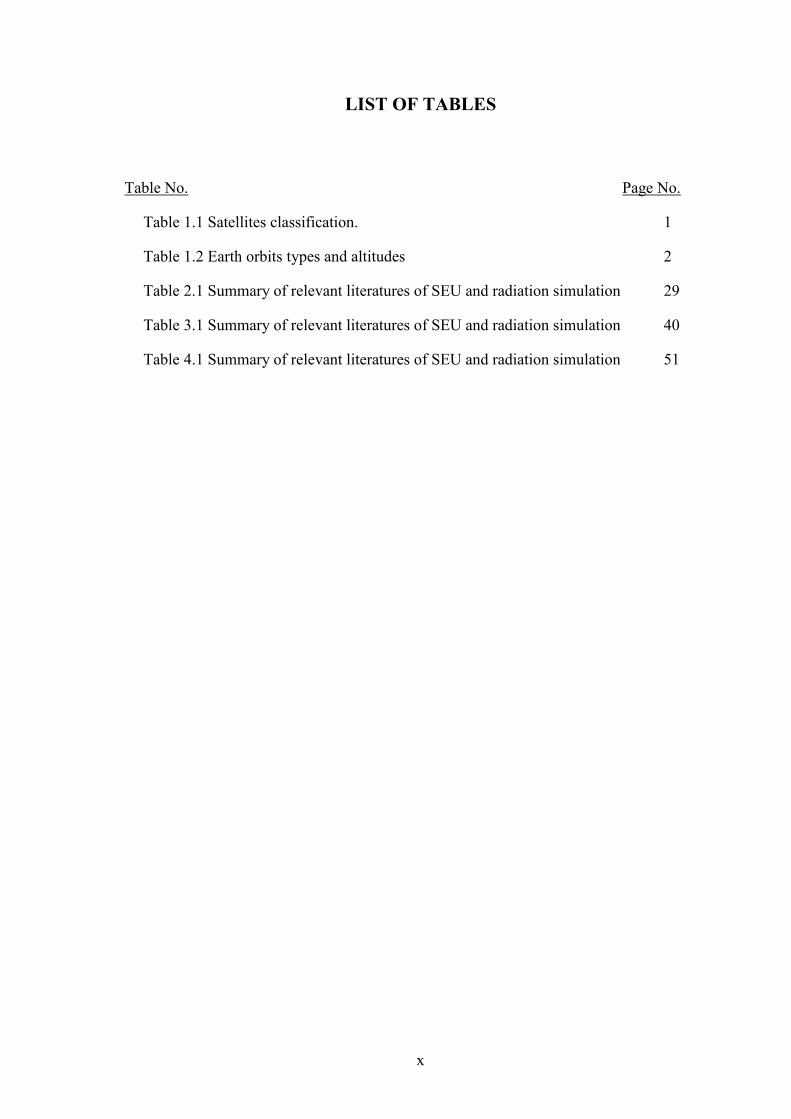
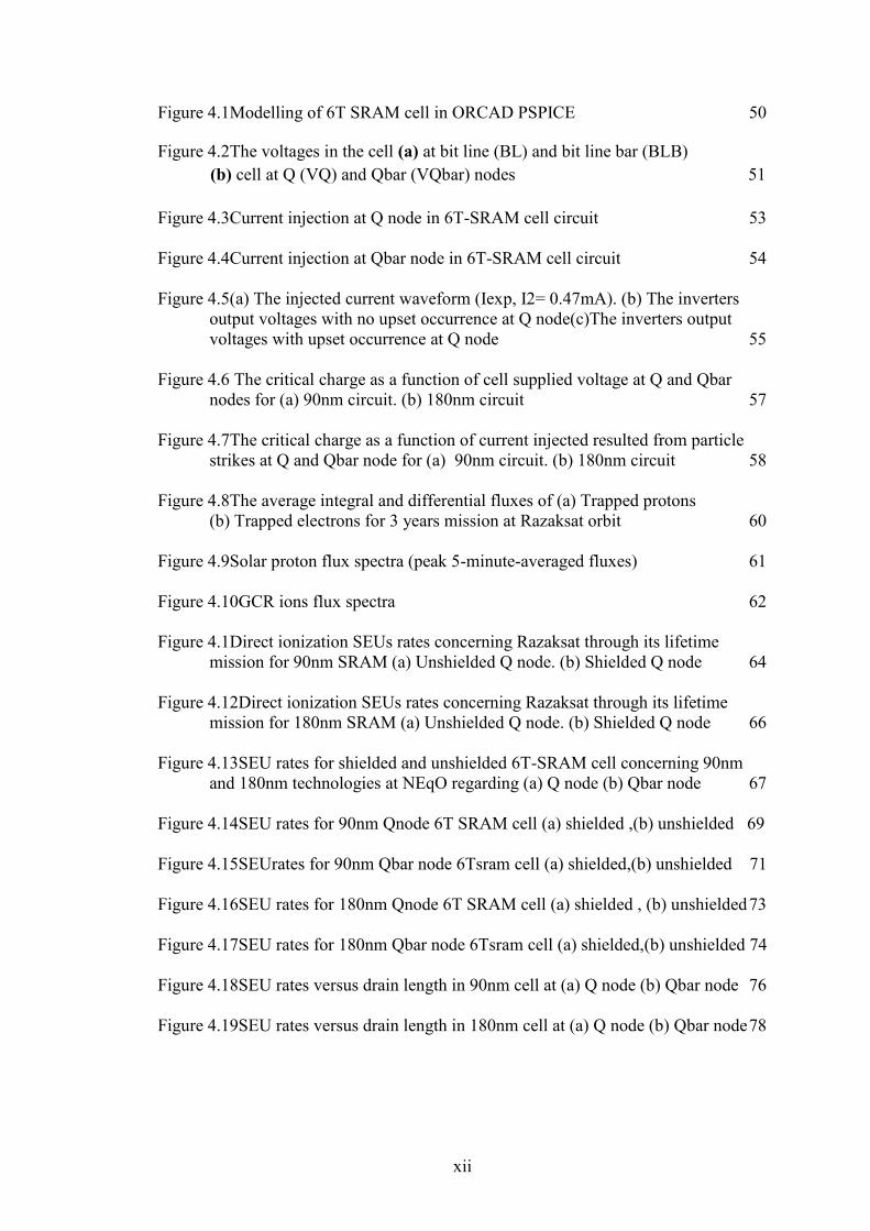
List of Figures ......................................................................................................... xi

List of Abbreviations ............................................................................................. xiii

List of Symbols ....................................................................................................... xi

CHAPTER ONE: INTRODUCTION .................................................................. 1 1.1 Background of The Study ....................................................................... 1

1.2 Problem Statement and Its Significance ................................................. 3 1.3 Research Scope ....................................................................................... 4

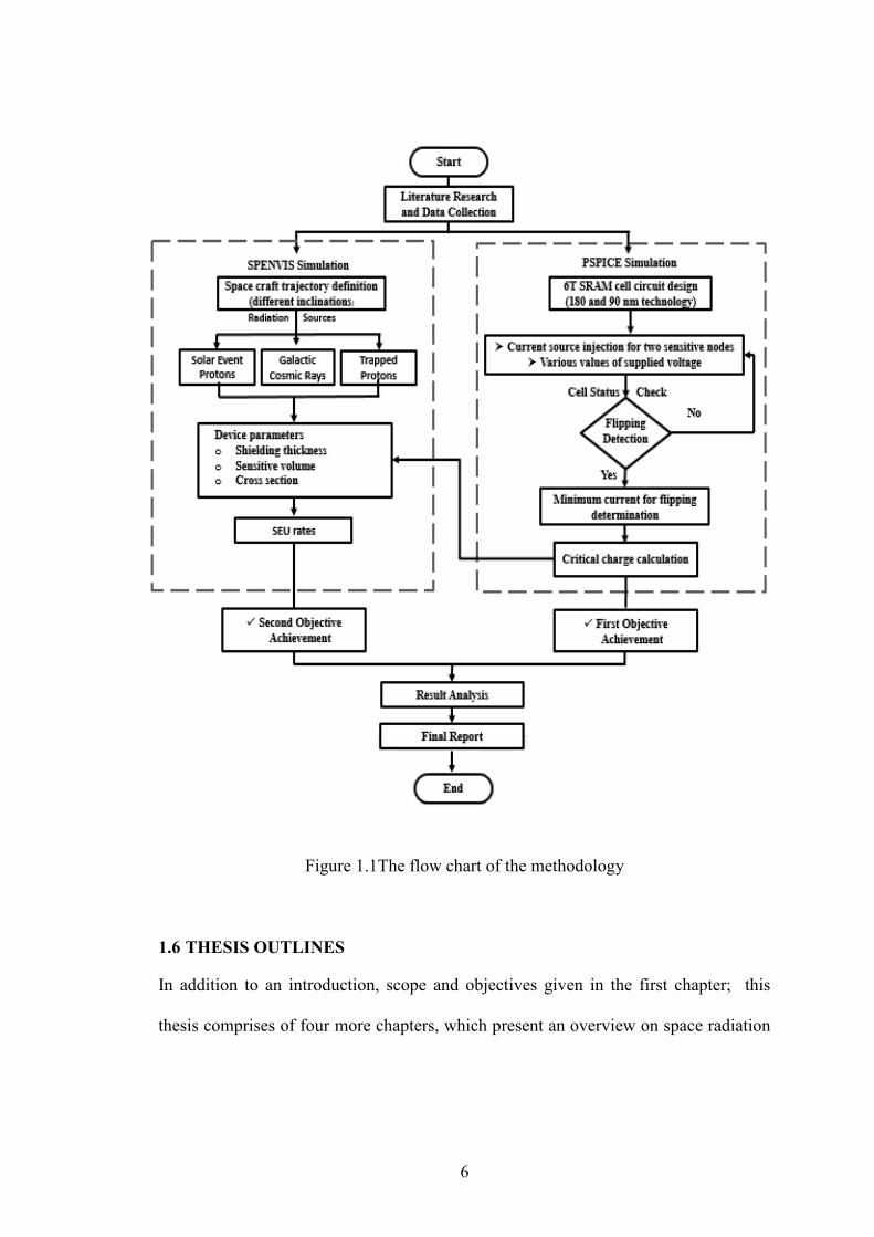
1.4 Research Objectives................................................................................ 4 1.5 Research Methodology ........................................................................... 5 1.6 Thesis Outlines ....................................................................................... 6

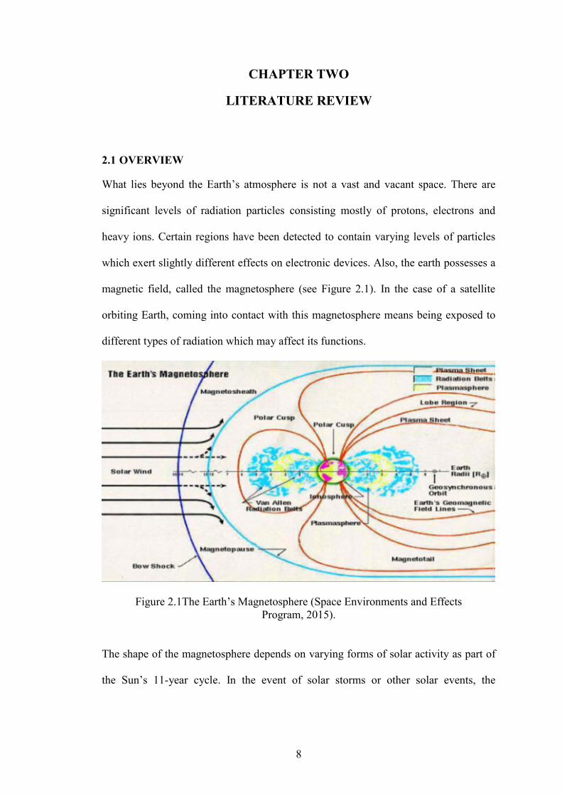
CHAPTER TWO: LITERATURE REVIEW ..................................................... 8 2.1 Overview................................................................................................. 8 2.2 Space Radiation Environment ................................................................ 10

2.2.1 Galactic Cosmic Rays (GCR) ....................................................... 10 2.2.2 Solar Particle Events (SPE)........................................................... 11

2.2.3 Trapped Particles (TP) .................................................................. 12 2.3 Single Event Upset (Seu) ........................................................................ 14

2.4 Direct and Indirect Ionization ................................................................. 15 2.4.1 Direct Ionization ........................................................................... 16 2.4.2 Indirect Ionization ......................................................................... 17

2.5 Static Random Access Memory (6t Cells).............................................. 17

2.6 Single Event Upset in 6t-Sram ............................................................... 18 2.7 The Critical Charge for SEU Inducement .............................................. 21 2.8 Previous Works ....................................................................................... 22

2.8.1 Radiation and SEUs ...................................................................... 22 2.8.2 Research on Distinct Orbits .......................................................... 24 2.8.3 Examples of Launched Satellites and Their Missions .................. 25 2.8.4 Examples of Launched Satellites and Their Missions .................. 26 2.8.5 The SEU in SRAM 6T Cells ......................................................... 27

2.8.6 Benchmarking Papers ................................................................... 28 2.9 Summary ................................................................................................. 30

CHAPTER THREE: METHODOLOGY ............................................................ 32 3.1 Overview................................................................................................. 32

ix

3.2 Simulation Details .................................................................................. 32 3.3 Pspice Simulation and Critical Charge Modelling ................................. 33

3.3.1 The 6T CMOS SRAM Cell Function ........................................... 34

3.3.1.1 Standby State .................................................................... 35 3.3.1.2 Reading State .................................................................... 35 3.3.1.3 Writing State ..................................................................... 36

3.3.2 Current Pulse Description For Simulated Circuit ......................... 37 3.4 Spenvis Models and Simulation ............................................................. 39

3.4.1 SPENVIS Coordinate Generator ................................................... 40 3.4.2 SPENVIS Radiation Models ......................................................... 41

3.4.2.1 Trapped Particles Model (AP8/AE8) ............................... 42 3.4.2.2 Solar Event Particules Model (CRÈME-96) .................... 43

3.4.2.3 Galactic Cosmic Rays Model (ISO 15390) ...................... 44 3.4.3 Short Term SEU Rates Models ..................................................... 44

3.4.3.1 The SEU Rates Induced by Direct Ionisation ................... 46

3.4.3.2 Soft Upset Rates Estimation Methods .............................. 47 3.5 Summary ................................................................................................. 48

CHAPTER FOUR: CRITICAL CHARGE (Qcrit) MODELLING and SINGLE

EVENT UPSET (SEU) RATES SIMULATION…………49

4.1 Overview................................................................................................. 49

4.2 Pspice Simulation ................................................................................... 49 4.2.1 The 6T-SRAM Cell Circuit before Radiation ............................... 49 4.2.2 6T SRAM Cell with Current Source Injection (After

Radiation) ..................................................................................... 52 4.3 SPENVIS Simulation ............................................................................. 58

4.3.1 Radiation Sources ......................................................................... 58 4.3.1.1 Trapped Protons and Electrons ......................................... 58

4.3.1.2 Reading State .................................................................... 60 4.3.1.3 Galactic Cosmic Rays (GCR) Ions ................................... 60

4.3.2 Single Event Upset Rates .............................................................. 61

4.3.2.1 Orbital Radiation Effects on SEU .................................... 61

4.3.2.2 Scaling Effects on SEU Rates .......................................... 65 4.3.2.3 Radiation Particules Type Effets on SEU ......................... 67 4.3.2.4 Drain Size Effects on SEU ............................................... 73

4.4 Summary ................................................................................................. 77

CHAPTER FIVE: CONCLUSIONS AND RECOMMENDATIONS .............. 78 5.1 Conclusions ............................................................................................ 78

5.2 Contribution ............................................................................................ 79 5.3 Limitations and Future Recommendations ............................................. 79

REFERENCES ....................................................................................................... 81

Appendix I ............................................................................................................... 81

Appendix II .............................................................................................................. 81

Appendix III ............................................................................................................. 90

Appendix IV ............................................................................................................. 92

x

LIST OF TABLES

Table No. Page No.

Table 1.1 Satellites classification. 1

Table 1.2 Earth orbits types and altitudes 2

Table 2.1 Summary of relevant literatures of SEU and radiation simulation 29

Table 3.1 Summary of relevant literatures of SEU and radiation simulation 40

Table 4.1 Summary of relevant literatures of SEU and radiation simulation 51

xi

LIST OF FIGURES

Figure No. Page No.

Figure1.1Flow Chart of Research Methodology 6

Figure 2.1The Earth’s Magnetosphere 8

Figure 2.2Van Allen radiation belts with two probes satellites flying through them 12

Figure 2.3Heavy ions and protons striking 15

Figure 2.4Transistor Memory Cell (6T Cell) 17

Figure 2.5An SEU in a memory cell due to a pulse strike 18

Figure 2.6Drain voltage waveforms for no upset, upset and in the upset threshold 19

Figure 2.7Sensitive areas and SEUs in a 6T-SRAM cell circuit 19

Figure 2.8Qcrit vs. cell supply voltage for particle strikes at off-NMOS/PMO 20

Figure 3.1Diagram of critical charge modeling by means of PSPICE 32

Figure 3.2Six-transistor (6T) CMOS SRAM cell 33

Figure 3.36T CMOS SRAM cell during a read operation 34

Figure 3.4The 6T CMOS SRAM cell during a write operation 35

Figure 3.5The current pulse sources and collection (a) the particle track

(b) The charge drift (c) the charge diffusion (d) the pulse curve 37

Figure 3.6The procedure for SEU rates calculation in SPENVIS 38

Figure 3.7 The three steps taken to define Razaksat coordinates 40

Figure 3.8The used trapped radiation models 41

Figure 3.9The used solar particle flux model 42

Figure 3.10The used Galactic Cosmic Rays Model 43

Figure 3.11Single Event Upsets model input parameters in SPENVIS 45

Figure 3.12Sensitive node shape and dimensions 46

xii

Figure 4.1Modelling of 6T SRAM cell in ORCAD PSPICE 50

Figure 4.2The voltages in the cell (a) at bit line (BL) and bit line bar (BLB)

(b) cell at Q (VQ) and Qbar (VQbar) nodes 51

Figure 4.3Current injection at Q node in 6T-SRAM cell circuit 53

Figure 4.4Current injection at Qbar node in 6T-SRAM cell circuit 54

Figure 4.5(a) The injected current waveform (Iexp, I2= 0.47mA). (b) The inverters

output voltages with no upset occurrence at Q node(c)The inverters output

voltages with upset occurrence at Q node 55

Figure 4.6 The critical charge as a function of cell supplied voltage at Q and Qbar

nodes for (a) 90nm circuit. (b) 180nm circuit 57

Figure 4.7The critical charge as a function of current injected resulted from particle

strikes at Q and Qbar node for (a) 90nm circuit. (b) 180nm circuit 58

Figure 4.8The average integral and differential fluxes of (a) Trapped protons

(b) Trapped electrons for 3 years mission at Razaksat orbit 60

Figure 4.9Solar proton flux spectra (peak 5-minute-averaged fluxes) 61

Figure 4.10GCR ions flux spectra 62

Figure 4.1Direct ionization SEUs rates concerning Razaksat through its lifetime

mission for 90nm SRAM (a) Unshielded Q node. (b) Shielded Q node 64

Figure 4.12Direct ionization SEUs rates concerning Razaksat through its lifetime

mission for 180nm SRAM (a) Unshielded Q node. (b) Shielded Q node 66

Figure 4.13SEU rates for shielded and unshielded 6T-SRAM cell concerning 90nm

and 180nm technologies at NEqO regarding (a) Q node (b) Qbar node 67

Figure 4.14SEU rates for 90nm Qnode 6T SRAM cell (a) shielded ,(b) unshielded 69

Figure 4.15SEUrates for 90nm Qbar node 6Tsram cell (a) shielded,(b) unshielded 71

Figure 4.16SEU rates for 180nm Qnode 6T SRAM cell (a) shielded , (b) unshielded 73

Figure 4.17SEU rates for 180nm Qbar node 6Tsram cell (a) shielded,(b) unshielded 74

Figure 4.18SEU rates versus drain length in 90nm cell at (a) Q node (b) Qbar node 76

Figure 4.19SEU rates versus drain length in 180nm cell at (a) Q node (b) Qbar node 78

xiii

LIST OF ABBREVIATIONS

6T SRAM Six Transistors Static Random Access Memory

Al Aluminum

BL Bit line

BLB Bit line bar

CMEs Coronal Mass Ejections

CMOS Complementary metal-oxide-semiconductor

ESA Space situational awareness

GaAs Gallium Arsenide

GCR Galactic cosmic rays

GEO Geostationary Earth Orbit

IRPP Integral rectangular parallelepiped

LEO Low Earth Orbit

LET Linear Energy Transfer

MCU Multiple Call Upset

NEqO NEar Equatorial Orbit

NMOS N-type metal-oxide-semiconductor

PMOS P-type metal-oxide-semiconductor

RPP Rectangular Parallelepiped

SAA South Atlantic Anomaly

SEB Single Event Burnout

SEE Single Event Effect

SEGR Single Event Gate Rapture

xiv

SEL Single Event Latch-up

Si Silicone

SP Solar Particles / Protons

SPE Solar Particle Events

SPENVIS Space Environment Information System

SWE Space Weather

TID Total Ionization Dose

TP Trapped Particles / Protons

xv

LIST OF SYMBOLS

A Ampere

GeV Gaga electro-volt

Icoll Collected current

Iexp Exponential current

Iinj Injected current

KeV Kilo electro-volt

MeV Mega electro- volt

mg/cm2 Milligram per centigram square

nm Nanometer

pfu Particle flux unit

Qcoll Collected charge

Qcrit Critical charge

Td Rise delay

Tf Fall delay

Vdd Supply voltage

τf Fall time

τr Rise time

1

CHAPTER ONE

INTRODUCTION

1.1 BACKGROUND OF THE STUDY

In this age, the fields of science, technology and the utilisation of computer

applications have become an important aspect in the development of nations. In that

Space technology is playing an increasingly important role in most space exploration

by modern societies. In particular, since the launching of the first artificial earth

satellite, known as Sputnik1, by the former Soviet union 58 years ago, this technology

has been under goingrapid development throughout the world. By December 2013,

sixty one (61) countries have successively launched their own satellites.

Nowadays, thousands of satellites are orbiting the Earth, providing services in

different fields including astronomy, communication, earth observation, military,

navigation, weather forecasting, scientific research and space stations. Satellites are

usually classified based on their mass (Farre Ponsa, 2012) as in Table 1.1.

Table 1.1 Satellites classification.

Satellite mass Satellite class

500 kg and above

100 – 500 kg

10 – 100 kg

1 – 10 kg

0.1 – 1 kg

Below 0.1 kg

Common satellite

Minisatellite

Microsatellite

Nanosatellite

Picosatellite

Femtosatellite

2

This has motivated scientists to design more advanced satellites, that have low

cost, low weight and low power consumption. For instance, a built prototype of a

femtosatellite type costs only $300 (Barnhart et al. 2009). Smaller satellites such as

AttoSatellites and ZeptoSatellites are aimed to be built with just a few dollars per unit

prototype (Tahri et al., 2013). Each spacecraft or satellite is designed based on its

objectives and working environment. This latter depends on the targeted orbit which

has to be accurately defined.

Basically, Earth has three types of orbits:

Low Earth Orbit (LEO): It has an altitude between 160 km and 2000 km, most

scientific and all manned satellites are placed in LEO.

Medium Earth Orbit (MEO): Acquires the height between 2000 and 35786 km,

below the geosynchronous orbit. The most prevalent use of satellites in this

orbit type is navigation, communication, space environment science and a

particular region supervision.

Geostationary Earth Orbit (GEO) is 35,786 km high up the Earth’s equator. A

geostationary satellite has a circular rotation pursuing the Earth’s movement

direction. A ground observer views the geostationary satellite as a motionless

object. It is worth highlighting that weather and communication satellites are

predominantly positioned in geostationary orbits. Table 1.2 summarizes the

attitude ranges of the three types of orbits ( Suparta & Zulkeple, 2014).

Table 1.2 Earth orbits types and altitudes

Low Earth Orbit

(LEO)

Middle Earth Orbit

(MEO)

Geostationary Earth Orbit

(GEO)

400 km

685 km

19,100 km

20,200 km

35,793 km

1000,000 km

3

Designing, building and launching a satellite is a time consuming process that

requires high budget. Therefore, its failure while in the space can cost hundreds of

millions dollars. Some of the hazardous elements in the space medium that can

damage a satellite include the radiation beltsaround the Earth, solar emissions, cosmic

rays, magnetic fields, plasma environments and space debris. As hardware technology

is advancing in capability, size of the electronic components is obviously shrinking

and satellites susceptibility to radiation impacts such as radiation damage, single event

impact (SEU) and charging is increasing (Baker, 2000). Therefore, when a space

mission is planned, a thorough investigation on the space environment and its

influence on the spacecraft’s microelectronics and astronaut’s safety has to be

conducted before launching.

In addition, investigating radiation problem mitigation through experimental

researches is considerably expensive and can cause undesirable side effects in

energetic radiation environment. The availability of advanced computer software and

simulation tools such as CREME96 (Tylka et al, 1997) and SPENVIS (Heynderickx et

al., 2004), which providing a gentle and inexpensive research tools can ensure the

device functionality and potentially saving money.

1.2 PROBLEM STATEMENT AND ITS SIGNIFICANCE

Highly ionizing cosmic rays and solar particles form a harsh radiation environment in

space they are found to be detrimental to spacecraft materials and devices. Several

radiation effects occur because of radiation environment. For instance, Single Event

Upset (SEU), a type of these effects as it is considered as a soft error, has a negative

effect on the spacecraft Static Random Access Memories (SRAMs). Moreover,

shrinking of transistor channel’s length in spacecraft devices will inevitably cause

4

effects such as SEU due to reduction in the critical charge. A spacecraft susceptibility

to SEU depends largely on their orbit, because each orbit has different radiation

levels. Near Equatorial Orbits (NEqO) are LEO orbits are categorized as a critical

orbit due to its maximum peak overpasses per day. High radiation levels are of much

interest to countries near to the equator such as Malaysia (RazakSAT) and Singapore

(TELEOS1).

Experimental analysis of the SEU problem is considerably expensive and

known to have undesirable side effects due to the emitted energetic radiation. The

availability of advanced and accurate computer software and simulation codes provide

safe and inexpensive research tools that can ensure reliable analysis of the device

functionality. It is envisioned that the finding of this project will have a major

importance in reliability enhancement and lifespan prolongation of RazakSAT, as

well as likewise the future of satellite generations.

1.3 RESEARCH SCOPE

This study explores and computes the natural cosmic radiation at Near Equatorial

Orbit (the orbit hovered by RasakSAT, Malaysian satellite) and investigates its SEU

effect on 6T SRAM, using two types of modeling software; SPENVIS and PSPICE.

1.4 RESEARCH OBJECTIVES

Based on the problem statement, the main goal of this research is to explore the SEUs

rates on 6T SRAM at Near Equatorial Orbit for RazakSAT. This goal can be allocated

as the following objectives:

5

1- To model 6T SRAM cell using PSPICE and to estimate the critical charge

variation for 90nm and 180nm CMOS technologies variability of

transistors models, injected with current and supplied voltage.

To analyze the critical charge effect obtained from PSPICE simulation on the SEU

rates at NEqO orbit (RazakSAT orbit) on specific sensitive volume using SPENVIS.

1.5 RESEARCH METHODOLOGY

The applied methodology to achieve the stated objectives is as follows in these

sequential steps:

1) Data collection of the needed information with critical analysis from previous

studies on SEUs and mechanism

2) Identify the key parameters adopted of the model.

3) Study the radiation environment with different particles, its energies, and

fluxes at near equatorial orbit.

4) Modelling the 6T SRAM behaviors of 6T SRAM with and without SEU.

5) Extract the critical charge as a function of supplied voltage, injected current

and CMOS transistor parameters using PSPICE software.

6) Extract the SEU rates correlated to the particle energy and critical charge,

based on data generated from previous simulation applying SPENVIS models.

7) Analyze, compare and report the outputs of the two models for SRAM

applications in equatorial environment.

The research methodology adopted for achieving the stated objectives is depicted in

Figure 1.1.

6

Figure 1.1The flow chart of the methodology

1.6 THESIS OUTLINES

In addition to an introduction, scope and objectives given in the first chapter; this

thesis comprises of four more chapters, which present an overview on space radiation

7

and a specific study regarding SEUs in 6T SRAM devices in the Near Equatorial

Orbit.

The second chapter is devoted to literature review; the properties specificat

space environment are given. In addition, the single event upset definition and

mechanism are explored.

The third chapter is dedicated to the methodology followed and the software

used in order extract details and statistics. The two mainly software used are:

SPENVIS for radiation modulation and PSPICE for circuit simulation and critical

charge calculation.

The fourth chapter provides results of the study and discusses the finding.

Here, the attained results are examined and compared with those from contemporary

findings on the subject.

Conclusions and further work suggestions are presented in the fifth chapter.

8

CHAPTER TWO

LITERATURE REVIEW

2.1 OVERVIEW

What lies beyond the Earth’s atmosphere is not a vast and vacant space. There are

significant levels of radiation particles consisting mostly of protons, electrons and

heavy ions. Certain regions have been detected to contain varying levels of particles

which exert slightly different effects on electronic devices. Also, the earth possesses a

magnetic field, called the magnetosphere (see Figure 2.1). In the case of a satellite

orbiting Earth, coming into contact with this magnetosphere means being exposed to

different types of radiation which may affect its functions.

Figure 2.1The Earth’s Magnetosphere (Space Environments and Effects

Program, 2015).

The shape of the magnetosphere depends on varying forms of solar activity as part of

the Sun’s 11-year cycle. In the event of solar storms or other solar events, the

9

magnetosphere is compressed which permits outside radiation particles to penetrate

into the magnetosphere and become trapped within.

Radiation exposure can cause significant damage to microelectronic circuits

and devices. This kind of damage can be categorized as Total ionizing dose (TID) and

single event effects (SEE). A TID is having a cumulative degradation of a device after

it has been exposed to ionizing radiation over a certain period of time. The second

most common type of damage known to be caused by the interaction of

semiconductor material and high-energy ionizing radiation is the so-called single

event effect (SEE). A SEE can be defined as an electrical disturbance occurring in a

semi-conductive microelectronic circuit caused by the passage of a single ionizing

high-energy space born particle (accelerator). When a single ionizing high-energy

particle penetrates into an electrical circuit, it leaves behind a dense plasma track in

the form of electron-hole pairs. Such a passage can cause a circuit error or even circuit

failure if a sufficiently high plasma charge is collected from the plasma track at a

sensitive node in the circuit.

The different types of SEEs can be classified into three most important and

frequent effects, listed as follows:

Single-event upset (SEU): a change of state or transient state induced by an

ionizing particle entering a device. The ionizing particle can be a cosmic ray or

a proton. This type of SEE can occur in digital, analog, and optical

components or in the surrounding circuitry.

Single-event latch up (SEL): a potentially destructive condition involving

parasitic circuit elements. If the increased current exceeds the device’s

maximum specification, it can destroy it if no safety measures are put in place

to limit the maximum current strength.


Recommended