196
Single-line lubrication systems Product catalogue
Single-linelubrication systems
Product catalogue

Lubrication systems catalogues
Single-line lubrication systems PUB LS/P1 17046 EN
Dual-line lubrication systems PUB LS/P1 16132 EN
Progressive lubrication systems PUB LS/P1 16964 EN
® SKF is a registered trademark of the SKF Group.® Lincoln is a registered trademark of Lincoln Industrial Corp.
© SKF Group 2016The contents of this publication are the copyright of the publisher and may not be reproduced (even extracts) unless prior written permission is granted. Every care has been taken to ensure the accuracy of the information contained in this publication but no liability can be accepted for any loss or damage whether direct, indirect or consequential arising out of the use of the information contained herein.
PUB LS/P1 17046 EN · January 2017
This publication supersedes publication 442832.
Certain image(s) used under license from Shutterstock.com
This catalogue contains the global range of SKF lubricationsystems products. Please contact your local country sales orcustomer service organization for availability in your area.

Navigation
Oil and fluid grease
Pumps and pump units . . . . . . . . . . . . . . 12
Metering devices . . . . . . . . . . . . . . . . . . . 46
Grease
Pumps and pump units . . . . . . . . . . . . . . 84
Metering devices . . . . . . . . . . . . . . . . . 120
System accessories
Controllers . . . . . . . . . . . . . . . . . . . . . . 138
Pressure sensors . . . . . . . . . . . . . . . . . . 162
Solenoid valves . . . . . . . . . . . . . . . . . . . 180
Oil a
nd flu
id g
rease
Grea
seAccesso
ries

4
PU
B L
S/P
1 1
7046 E
N
Two leading brands . . . . . . . . . . . . . . . . . . . . . . . . . . . . . . . . . . 8
Classification of lubricants . . . . . . . . . . . . . . . . . . . . . . . . . . . . 9
Single-line lubrication systems for oil and fluid grease . . . . 10
System description . . . . . . . . . . . . . . . . . . . . . . . . . . . . . . .10
Overview of oil and fluid grease pumps and pump units . . . 13
1812 . . . . . . . . . . . . . . . . . . . . . . . . . . . . . . . . . . . . . . . . . .14
POE . . . . . . . . . . . . . . . . . . . . . . . . . . . . . . . . . . . . . . . . . . .15
PFE . . . . . . . . . . . . . . . . . . . . . . . . . . . . . . . . . . . . . . . . . . .16
82885, 83667 . . . . . . . . . . . . . . . . . . . . . . . . . . . . . . . . . .17
85438/40/41 . . . . . . . . . . . . . . . . . . . . . . . . . . . . . . . . . . .18
P / PW / PF / PFW-289 . . . . . . . . . . . . . . . . . . . . . . . . . . . . .19
POEP . . . . . . . . . . . . . . . . . . . . . . . . . . . . . . . . . . . . . . . . .20
PFEP . . . . . . . . . . . . . . . . . . . . . . . . . . . . . . . . . . . . . . . . . .21
PPS30 . . . . . . . . . . . . . . . . . . . . . . . . . . . . . . . . . . . . . . . .22
82676 . . . . . . . . . . . . . . . . . . . . . . . . . . . . . . . . . . . . . . . . .24
82570 . . . . . . . . . . . . . . . . . . . . . . . . . . . . . . . . . . . . . . . . .25
85430/31/32/33 . . . . . . . . . . . . . . . . . . . . . . . . . . . . . . . .26
PEF/PEU . . . . . . . . . . . . . . . . . . . . . . . . . . . . . . . . . . . . . . .27
283167 . . . . . . . . . . . . . . . . . . . . . . . . . . . . . . . . . . . . . . .28
1826 . . . . . . . . . . . . . . . . . . . . . . . . . . . . . . . . . . . . . . . . . .29
ECP . . . . . . . . . . . . . . . . . . . . . . . . . . . . . . . . . . . . . . . . . . .30
P 653S (oil) . . . . . . . . . . . . . . . . . . . . . . . . . . . . . . . . . . . . .32
KFB . . . . . . . . . . . . . . . . . . . . . . . . . . . . . . . . . . . . . . . . . . .34
KFB-M . . . . . . . . . . . . . . . . . . . . . . . . . . . . . . . . . . . . . . . .36
KFU . . . . . . . . . . . . . . . . . . . . . . . . . . . . . . . . . . . . . . . . . . .38
MKU . . . . . . . . . . . . . . . . . . . . . . . . . . . . . . . . . . . . . . . . . .40
MKF . . . . . . . . . . . . . . . . . . . . . . . . . . . . . . . . . . . . . . . . . .42
MFE . . . . . . . . . . . . . . . . . . . . . . . . . . . . . . . . . . . . . . . . . .44
Overview of oil and fluid grease metering devices . . . . . . . . 47
341 . . . . . . . . . . . . . . . . . . . . . . . . . . . . . . . . . . . . . . . . . . .48
340 . . . . . . . . . . . . . . . . . . . . . . . . . . . . . . . . . . . . . . . . . . .50
LS22 . . . . . . . . . . . . . . . . . . . . . . . . . . . . . . . . . . . . . . . . . .52
LS21 . . . . . . . . . . . . . . . . . . . . . . . . . . . . . . . . . . . . . . . . . .53
361 . . . . . . . . . . . . . . . . . . . . . . . . . . . . . . . . . . . . . . . . . . .54
351 . . . . . . . . . . . . . . . . . . . . . . . . . . . . . . . . . . . . . . . . . . .56
350 . . . . . . . . . . . . . . . . . . . . . . . . . . . . . . . . . . . . . . . . . . .58
370 . . . . . . . . . . . . . . . . . . . . . . . . . . . . . . . . . . . . . . . . . . .60
391 . . . . . . . . . . . . . . . . . . . . . . . . . . . . . . . . . . . . . . . . . . .62
390 . . . . . . . . . . . . . . . . . . . . . . . . . . . . . . . . . . . . . . . . . . .64
321 G, T, W, G4, Module, G7 . . . . . . . . . . . . . . . . . . . . . . . .66
AB . . . . . . . . . . . . . . . . . . . . . . . . . . . . . . . . . . . . . . . . . . . .68
VN . . . . . . . . . . . . . . . . . . . . . . . . . . . . . . . . . . . . . . . . . . . .70
OI-AL-SR . . . . . . . . . . . . . . . . . . . . . . . . . . . . . . . . . . . . . .72
SL-42 . . . . . . . . . . . . . . . . . . . . . . . . . . . . . . . . . . . . . . . . .74
SL-43 . . . . . . . . . . . . . . . . . . . . . . . . . . . . . . . . . . . . . . . . .76
SL-41 . . . . . . . . . . . . . . . . . . . . . . . . . . . . . . . . . . . . . . . . .78
SL-44 . . . . . . . . . . . . . . . . . . . . . . . . . . . . . . . . . . . . . . . . .80
Single-line lubrication systems for grease . . . . . . . . . . . . . . 82
System description . . . . . . . . . . . . . . . . . . . . . . . . . . . . . . .82
Overview of grease pumps and pump units . . . . . . . . . . . . . 85
83817 . . . . . . . . . . . . . . . . . . . . . . . . . . . . . . . . . . . . . . . . .88
1810 . . . . . . . . . . . . . . . . . . . . . . . . . . . . . . . . . . . . . . . . . .89
40PGA . . . . . . . . . . . . . . . . . . . . . . . . . . . . . . . . . . . . . . . .90
82886, 83668 . . . . . . . . . . . . . . . . . . . . . . . . . . . . . . . . . .92
85442 . . . . . . . . . . . . . . . . . . . . . . . . . . . . . . . . . . . . . . . . .93
85444/45 . . . . . . . . . . . . . . . . . . . . . . . . . . . . . . . . . . . . . .94
85434/35/36 . . . . . . . . . . . . . . . . . . . . . . . . . . . . . . . . . . .95
82653/55, 83800/34 . . . . . . . . . . . . . . . . . . . . . . . . . . . . .96
83167 . . . . . . . . . . . . . . . . . . . . . . . . . . . . . . . . . . . . . . . . .97
83599 . . . . . . . . . . . . . . . . . . . . . . . . . . . . . . . . . . . . . . . . .98
84050, 85460 . . . . . . . . . . . . . . . . . . . . . . . . . . . . . . . . . .99
282288 . . . . . . . . . . . . . . . . . . . . . . . . . . . . . . . . . . . . . .100
HG 1000, HG 2000 . . . . . . . . . . . . . . . . . . . . . . . . . . . . . .101
84944, 84961 . . . . . . . . . . . . . . . . . . . . . . . . . . . . . . . . .102
84960, 84962 . . . . . . . . . . . . . . . . . . . . . . . . . . . . . . . . .103
FlowMaster, hydraulic . . . . . . . . . . . . . . . . . . . . . . . . . . . .104
P 603S . . . . . . . . . . . . . . . . . . . . . . . . . . . . . . . . . . . . . . .106
Minilube . . . . . . . . . . . . . . . . . . . . . . . . . . . . . . . . . . . . . .108
KFG . . . . . . . . . . . . . . . . . . . . . . . . . . . . . . . . . . . . . . . . . .110
Multilube, MLP . . . . . . . . . . . . . . . . . . . . . . . . . . . . . . . . .112
P653S . . . . . . . . . . . . . . . . . . . . . . . . . . . . . . . . . . . . . . .114
FK . . . . . . . . . . . . . . . . . . . . . . . . . . . . . . . . . . . . . . . . . . .116
FlowMaster, electric . . . . . . . . . . . . . . . . . . . . . . . . . . . . . .118
Overview of grease metering devices . . . . . . . . . . . . . . . . .121
SL-33 . . . . . . . . . . . . . . . . . . . . . . . . . . . . . . . . . . . . . . . .122
B-doser . . . . . . . . . . . . . . . . . . . . . . . . . . . . . . . . . . . . . .124
LG-doser . . . . . . . . . . . . . . . . . . . . . . . . . . . . . . . . . . . . . .126
SL-32HV . . . . . . . . . . . . . . . . . . . . . . . . . . . . . . . . . . . . . .128
SL-1 . . . . . . . . . . . . . . . . . . . . . . . . . . . . . . . . . . . . . . . . .129
QSL . . . . . . . . . . . . . . . . . . . . . . . . . . . . . . . . . . . . . . . . . .130
VR . . . . . . . . . . . . . . . . . . . . . . . . . . . . . . . . . . . . . . . . . . .132
SL-11 . . . . . . . . . . . . . . . . . . . . . . . . . . . . . . . . . . . . . . . .134
SL-V . . . . . . . . . . . . . . . . . . . . . . . . . . . . . . . . . . . . . . . . .135
SL-V XL . . . . . . . . . . . . . . . . . . . . . . . . . . . . . . . . . . . . . . .136
Content

5
PU
B L
S/P
1 1
7046 E
N
Overview of controllers . . . . . . . . . . . . . . . . . . . . . . . . . . . .139
EXZT / IGZ . . . . . . . . . . . . . . . . . . . . . . . . . . . . . . . . . . . . .140
IG502-2-E . . . . . . . . . . . . . . . . . . . . . . . . . . . . . . . . . . . .142
LC502 . . . . . . . . . . . . . . . . . . . . . . . . . . . . . . . . . . . . . . . .143
ST–1340 and ST–1440 . . . . . . . . . . . . . . . . . . . . . . . . . .144
ST-1240-GRAPH / -4 . . . . . . . . . . . . . . . . . . . . . . . . . . . .145
ST-1100i . . . . . . . . . . . . . . . . . . . . . . . . . . . . . . . . . . . . .146
ST-102 . . . . . . . . . . . . . . . . . . . . . . . . . . . . . . . . . . . . . . .147
ST-102P . . . . . . . . . . . . . . . . . . . . . . . . . . . . . . . . . . . . . .148
84501 . . . . . . . . . . . . . . . . . . . . . . . . . . . . . . . . . . . . . . . .149
84015 . . . . . . . . . . . . . . . . . . . . . . . . . . . . . . . . . . . . . . . .150
85520 . . . . . . . . . . . . . . . . . . . . . . . . . . . . . . . . . . . . . . . .151
85535 . . . . . . . . . . . . . . . . . . . . . . . . . . . . . . . . . . . . . . . .152
85530 . . . . . . . . . . . . . . . . . . . . . . . . . . . . . . . . . . . . . . . .153
LMC 101 . . . . . . . . . . . . . . . . . . . . . . . . . . . . . . . . . . . . . .154
EOT-1/2 664-34135-6, 664-34135-7 . . . . . . . . . . . . . .155
LMC 301 . . . . . . . . . . . . . . . . . . . . . . . . . . . . . . . . . . . . . .156
LMC 2 . . . . . . . . . . . . . . . . . . . . . . . . . . . . . . . . . . . . . . . .157
85525 . . . . . . . . . . . . . . . . . . . . . . . . . . . . . . . . . . . . . . . .158
85209, 85208 . . . . . . . . . . . . . . . . . . . . . . . . . . . . . . . . .159
HCC . . . . . . . . . . . . . . . . . . . . . . . . . . . . . . . . . . . . . . . . . .160
Flow sensor . . . . . . . . . . . . . . . . . . . . . . . . . . . . . . . . . . . .161
Overview of pressure sensors . . . . . . . . . . . . . . . . . . . . . . .163
DSA . . . . . . . . . . . . . . . . . . . . . . . . . . . . . . . . . . . . . . . . . .164
DSB1 . . . . . . . . . . . . . . . . . . . . . . . . . . . . . . . . . . . . . . . .166
DSC1 . . . . . . . . . . . . . . . . . . . . . . . . . . . . . . . . . . . . . . . .168
DSC2 . . . . . . . . . . . . . . . . . . . . . . . . . . . . . . . . . . . . . . . .169
DSC3 . . . . . . . . . . . . . . . . . . . . . . . . . . . . . . . . . . . . . . . .170
247333 . . . . . . . . . . . . . . . . . . . . . . . . . . . . . . . . . . . . . .171
DSD . . . . . . . . . . . . . . . . . . . . . . . . . . . . . . . . . . . . . . . . .172
69630 . . . . . . . . . . . . . . . . . . . . . . . . . . . . . . . . . . . . . . . .174
234-11145-3, -4, -5, -9 . . . . . . . . . . . . . . . . . . . . . . . . .175
234-10330-4 . . . . . . . . . . . . . . . . . . . . . . . . . . . . . . . . .176
234-13161-... . . . . . . . . . . . . . . . . . . . . . . . . . . . . . . . . .177
234-10663-1 . . . . . . . . . . . . . . . . . . . . . . . . . . . . . . . . .178
234-10825-8 . . . . . . . . . . . . . . . . . . . . . . . . . . . . . . . . .179
Overview of solenoid valves . . . . . . . . . . . . . . . . . . . . . . . . .181
35024 ... . . . . . . . . . . . . . . . . . . . . . . . . . . . . . . . . . . . . . .182
350282, 350283 . . . . . . . . . . . . . . . . . . . . . . . . . . . . . . .183
253-14076-X . . . . . . . . . . . . . . . . . . . . . . . . . . . . . . . . . .184
525-320 ...-1 . . . . . . . . . . . . . . . . . . . . . . . . . . . . . . . . . .185
161-110-031 . . . . . . . . . . . . . . . . . . . . . . . . . . . . . . . . .186
161-140-050 . . . . . . . . . . . . . . . . . . . . . . . . . . . . . . . . .187
6
PU
B L
S/P
1 1
7046 E
N
From one simple but
inspired solution to
a misalignment
problem in a textile
mill in Sweden, and
fifteen employees in
1907, SKF has
grown to become a
global industrial
knowledge leader.
Over the years we have built on our exper-
tise in bearings, extending it to seals, mecha-
tronics, services and lubrication systems.
Our knowledge network includes 46 000
employees, 15 000 distributor partners,
offices in more than 130 countries, and a
growing number of SKF Solution Factory
sites around the world.
Research and development
We have hands-on experience in over forty
industries, based on our employees’ know-
ledge of real life conditions. In addition our
world-leading experts and university part-
ners who pioneer advanced theoretical
research and development in areas includ-
ing tribology, condition monitoring, asset
management and bearing life theory. Our
ongoing commitment to research and
devel opment helps us keep our customers
at the forefront of their industries.
Meeting the toughest challenges
Our network of knowledge and experience
along with our understanding of how our
core technologies can be combined helps
us create innovative solutions that meet the
toughest of challenges. We work closely with
our customers throughout the asset life
cycle, helping them to profitably and
re spon sibly grow their businesses.
SKF Solution Factory makes SKF knowledge and manu facturing expertise available locally, to provide unique solutions and services to our customers.
Working with SKF IT and logistics systems and application experts, SKF Authorized Distributors deliver a valuable mix of product and application knowledge to customers worldwide.
Working for a sustainable future
Since 2005, SKF has worked to reduce the
negative environmental impact from our
own operations and those of our suppliers.
Our continuing technology development
intro duced the SKF BeyondZero portfolio
of products and services which improve
efficiency and reduce energy losses, as well
as enable new technol ogies harnessing
wind, solar and ocean power. This combined
approach helps reduce the environmental
impact both in our own oper ations and in
our customers’.
SKF – the knowledge engineering company

7
PU
B L
S/P
1 1
7046 E
N
BearingsSKF is the world leader in the design, development and manufacture of high performance rolling bearings, plain bearings, bearing units and housings.
Machinery maintenanceCondition monitoring technologies and main-tenance services from SKF can help minimize unplanned downtime, improve operational efficiency and reduce maintenance costs.
Sealing solutionsSKF offers standard seals and custom engineered sealing solutions to increase uptime, improve machine reliability, reduce friction and power losses, and extend lubricant life.
MechatronicsSKF fly-by-wire systems for aircraft and drive-by-wire systems for off-road, agricultural and forklift applications replace heavy, grease or oil consuming mechanical and hydraulic systems.
Lubrication solutionsFrom specialized lubricants to state-of-the-art lubrication systems and lubrication management ser vices, lubrication solutions from SKF can help to reduce lubrication related downtime and lubricant consumption.
Actuation and motion controlWith a wide assortment of products – from actu-ators and ball screws to profile rail guides – SKF can work with you to solve your most pressing linear system challenges.
Our knowledge – your successSKF Life Cycle Management is how we combine our technology
platforms and advanced ser vices, and apply them at each stage
of the asset life cycle, to help our customers to be more
success ful, sustainable and profitable.
Working closely with you
Our objective is to help our customers
improve productivity, minimize main ten-
ance, achieve higher energy and resource
efficiency, and optimize designs for long
service life and reliability.
Innovative solutions
Whether the application is linear or rotary
or a combination of the two, SKF engineers
can work with you at each stage of the asset
life cycle to improve machine performance
by looking at the entire application. This
approach doesn’t just focus on individual
components like bearings or seals. It looks
at the whole application to see how each
com po nent interacts with the next.
Design optimization and verification
SKF can work with you to optimize current
or new designs with proprietary 3-D model-
ing software that can also be used as a vir-
tual test rig to confirm the integrity of the
design.
SKF Life Cycle Management
Design and developManufacture and test
Spec
ifica
tion
Install a
nd com
mis
sion
Operate and monitor
Maintain and repair

8
Oil a
nd flu
id g
rease
Gre
ase
PU
B L
S/P
1 1
7046 E
N
Two leading brands
One global leader
SKF and Lincoln have joined forces to pro-
vide you with the world’s most complete
portfolio of innovative lubrication solutions
– from manual lubricators and tools, to the
most advanced centralized and automatic
lubrication systems available.
In addition to traditional lubrication products
and systems, we offer customized solutions
for many industries such as pulp and paper,
steel, mining, agriculture, marine, rail, wind,
construction, machine tool and automotive.
SKF engineering and technical specialists
partner with OEMs and end-users to devel-
op system solutions based on customer
requirements. We also offer a variety of con-
trol and monitoring equipment for ease of
use and to help ensure proper lubrication.
Both SKF and Lincoln systems are available
through our global network of lubrication
experts, offering you world-class installation
and ongoing support on a local level – today
and into the future. With the power of this
network, and more than 200 years of com-
bined friction management experience, we
can help you improve machine reliability, re-
duce maintenance, increase productivity,
enhance safety and optimize manpower
resources.
9
PU
B L
S/P
1 1
7046 E
N
Classification of lubricants
Oil a
nd flu
id g
rease
Grea
se
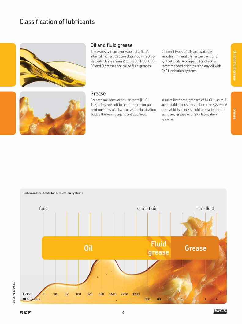
Lubricants suitable for lubrication systems
ISO VG 3 10 32 100 320 680 1500 2200 3200
N LGI grades 000 00 0 1 2 3 4
fluid semi-fluid non-fluid
OilFluid
greaseGrease
Oil and fluid greaseThe viscosity is an expression of a fluid’s
internal friction. Oils are classified in ISO VG
viscosity classes from 2 to 3 200. NLGI 000,
00 and 0 greases are called fluid greases.
GreaseGreases are consistent lubricants (NLGI
1–6). They are soft to hard, triple-compo-
nent mixtures of a base oil as the lubricating
fluid, a thickening agent and additives.
Different types of oils are available,
including mineral oils, organic oils and
synthetic oils. A compatibility check is
recommended prior to using any oil with
SKF lubrication systems.
In most instances, greases of NLGI 1 up to 3
are suitable for use in a lubrication system. A
compatibility check should be made prior to
using any grease with SKF lubrication
systems.
10
Oil a
nd flu
id g
rease
PU
B L
S/P
1 1
7046 E
N
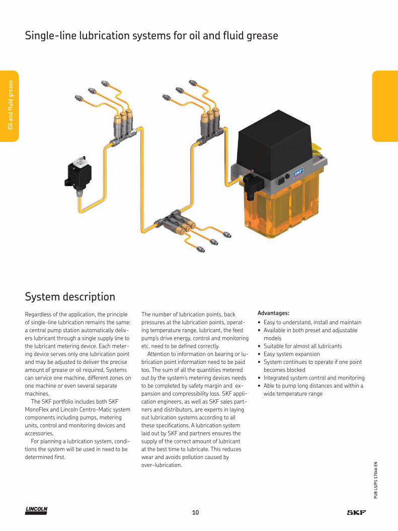
Regardless of the application, the principle
of single-line lubrication remains the same:
a central pump station automatically deliv-
ers lubricant through a single supply line to
the lubricant metering device. Each meter-
ing device serves only one lubrication point
and may be adjusted to deliver the precise
amount of grease or oil required. Systems
can service one machine, different zones on
one machine or even several separate
machines.
The SKF portfolio includes both SKF
MonoFlex and Lincoln Centro-Matic system
components including pumps, metering
units, control and monitoring devices and
accessories.
For planning a lubrication system, condi-
tions the system will be used in need to be
determined first.
The number of lubrication points, back
pressures at the lubrication points, operat-
ing temperature range, lubricant, the feed
pump’s drive energy, control and monitoring
etc. need to be defined correctly.
Attention to information on bearing or lu-
brication point information need to be paid
too. The sum of all the quantities metered
out by the system’s metering devices needs
to be completed by safety margin and ex-
pansion and compressibility loss. SKF appli-
cation engineers, as well as SKF sales part-
ners and distributors, are experts in laying
out lubrication systems according to all
these specifications. A lubrication system
laid out by SKF and partners ensures the
supply of the correct amount of lubricant
at the best time to lubricate. This reduces
wear and avoids pollution caused by
over-lubrication.
Advantages:
• Easy to understand, install and maintain
• Available in both preset and adjustable
models
• Suitable for almost all lubricants
• Easy system expansion
• System continues to operate if one point
becomes blocked
• Integrated system control and monitoring
• Able to pump long distances and within a
wide temperature range
System description
Single-line lubrication systems for oil and fluid grease

11
Oil a
nd flu
id g
rease
PU
B L
S/P
1 1
7046 E
N
System and applications
Applications
In total loss lubrication systems, fresh lubri-
cant is fed to friction points during a lubrica-
tion cycle. The lubrication cycle is set up so
that friction points are supplied with enough
lubricant to build up an adequate film of lu-
bricant, reducing wear and tear on bearings
and friction points. Monoflex and Centro-
matic systems are designed to allow for easy
expansion and simple assembly.
Applications for single-line systems
include small-to-medium machine tools,
mobile on-road (fleet vehicles, on-road
transport), and assembly/automation food
packaging, part assembly lines and injection
molding:
• Small-to-medium line length
• Small-to-medium quantities of
lubricant per lubrication point
• Ease of expansion
• Linear layout of lubrication points
• Flexibility of lubricant distribution
• Easy monitoring of lubrication distribution

POE/PFE P / PW / PF / PFW-289
PEF / PEU
1812
85430 / 31 / 32 / 33
85438 / 40 / 4182885 / 83667
82676 / 82570 283167 1826PPS30
KFU MFEMKxKFB / KFB-M
POEP / PFEP
P653S (oil)
Pumps and pump units
Oil
and flu
id g
reas
e
Single-line lubrication systems
ECP
12
PU
B L
S/P
1 1
7046 E
N
Oil a
nd flu
id g
rease

13
PU
B L
S/P
1 1
7046 E
N
Oil a
nd flu
id g
rease
Overview of oil and fluid grease pumps and pump units
Manually operated pumps and pump units
Product Lubricant Metering quantity Operating Reservoir Metering Pageoil grease: pressure device
000/00 max. category 1)
cm 3/ stroke in3/ stroke bar psi l gal
1812 • • 2,6 0.16 69 1 000 2,1 0.55 2, 3, 4 14POE • – 15 0.9 30 435 0,5; 1; 1,7 0.13; 0.26; 0.45 1, 2 15PFE – • 15 0.9 30 435 0,5; 1; 1,7 0.13; 0.26; 0.45 1, 2 16
1) Select the recommended fittings, adjust the pump pressure within the recommended metering device pressure range2) Controller optionally
1) Select the recommended fittings, adjust the pump pressure within the recommended metering device pressure range
1) Select the recommended fittings, adjust the pump pressure within the recommended metering device pressure range2) Controller optionally3) With pressure transducer
Air-operated pumps and pump units
Product Lubricant Metering quantity Operating Reservoir Metering Pageoil grease: pressure device
000/00 max. category 1)
cm 3/ stroke in3/ stroke bar psi l gal
82885, 83667 • • 7,4 0.45 69 1 000 0,6; 2 0.16; 0.53 2, 3, 4 1785438/40/41 2) • • 7,4 0.45 69 1 000 0,6; 2 0.16; 0.53 2, 3, 4 18P/PW/PF/PFW-289 • • 10 0.61 10 145 1,5 0.39 1, 2, 3 19POEP • – 15 0.9 60 870 0,5; 1; 1,7 0.13; 0.26; 0.45 1, 2, 3, 4 20PFEP – • 15 0.9 60 870 0,5; 1; 1,7 0.13; 0.26; 0.45 1, 2, 3, 4 21PPS30 • • 30 1.83 27 392 1,5 0.39 1, 2 22
82676 • • 39,3 2.39 69 1 000 – – 4 2482570 • • 39,3 2.39 69 1 000 2 0.53 4 2585430/31/32/33 2) • • 39,3 2.39 69 1 000 0,0; 2 0.0; 0.53 4 26PEF/PEU • • 48 2.93 10 145 3 0.79 1, 2, 3 27
cm 3/ min in3/ min bar psi l gal
283167 • • 197 12.02 69 1 000 7,1 1.88 3, 4 281826 2) • • 7 571 462 69 1 000 200 52.83 2, 3, 4 29
Electrically operated pumps and pump units
Product Lubricant Metering quantity Operating Reservoir Metering Pageoil grease: pressure device
000/00 max. category 1)
cm 3/ min in3/ min bar psi l gal
ECP • • 12 0.73 38 550 0,38 0.086 1, 2, 3 30P653S (oil) 2) 3) • • 24,6 1.5 240 3500 4; 8 1.05; 2.11 2, 3, 4 32KFB 2) • • 50 3 38 550 1 0.26 1, 2, 3 34KFB-M 2) • • 50 3 38 550 1 0.26 1, 2, 3 36KFU • • 140 8.5 38 550 2,7; 6 0.71; 1.56 1, 2, 3 38MKU 2) • – 100; 200;
5006; 12; 31 30 435 2; 3; 6 0.53; 0.79; 1.56 1 40
MKF 2) • • 100; 200; 500
6; 12; 31 30 435 2; 3; 6 0.53; 0.79; 1.56 1, 2 42
MFE • • 250; 500 15; 31 28 405 3; 6; 15 0.79; 1.56; 3.96 1, 2 44

14
PU
B L
S/P
1 1
7046 E
N
Oil a
nd flu
id g
rease
Product description
The 1812 pump features a translucent reservoir with filler cap and
strainer. Its pump base has an integrated check/vent valve and an
indicator pin to show when system pressure is achieved.
Features and benefits
• Provides precise lubrication where air
or electricity are not available
• Built-in vent valve activates when handle
is pushed all the way up
• Pressure stem indicates 58 bar; 850 psi
• Suitable for use with metering devices of category 2, 3, 4
Applications
• Textile
• Stationary
• Material handling including presses
• Agriculture and farming
Technical data
Order number . . . . . . . . . . . . 1812Function principle . . . . . . . . . manually operated piston pumpOutlets. . . . . . . . . . . . . . . . . . 1Metering quantity . . . . . . . . . 2,6 cm 3/ stroke , 0.16 in3/ stroke Lubricant. . . . . . . . . . . . . . . . oil, synthetic oil on requestOperating temperature . . . . . –23 to +65 °C
–10 to +150 °F Operating pressure . . . . . . . . max. 70 bar, 1 000 psiReservoir. . . . . . . . . . . . . . . . 2,13 l; 2 130 cm 3
0.5 gal, 130 in3
Material (reservoir) . . . . . . . . acrylicConnection outlet . . . . . . . . . 1/4 NPTF (F)Dimensions . . . . . . . . . . . . . . 425 × 181 × 197 mm
16.75 × 7.125 × 7.75 inMounting position . . . . . . . . . vertical
Pump unit
1812
15
PU
B L
S/P
1 1
7046 E
N
Oil a
nd flu
id g
rease
Product description
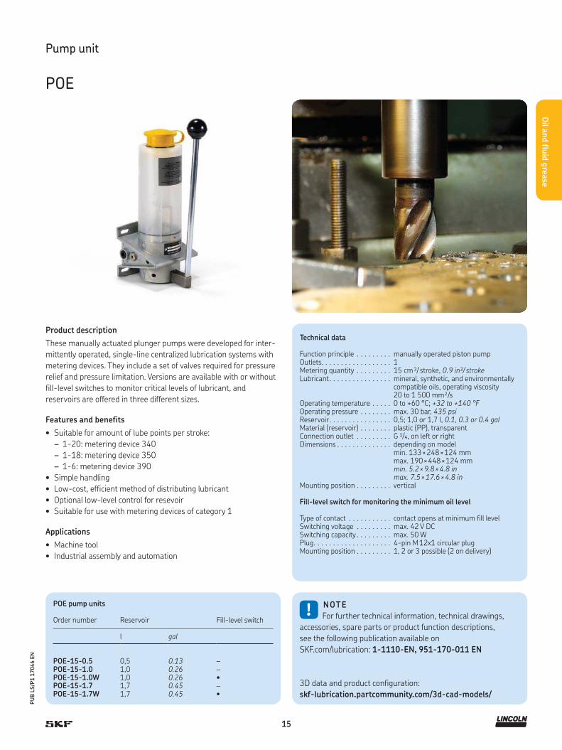
These manually actuated plunger pumps were developed for inter-
mittently operated, single-line centralized lubrication systems with
metering devices. They include a set of valves required for pressure
relief and pressure limitation. Versions are available with or without
fill-level switches to monitor critical levels of lubricant, and
reservoirs are offered in three different sizes.
Features and benefits
• Suitable for amount of lube points per stroke:
– 1-20: metering device 340
– 1-18: metering device 350
– 1-6: metering device 390
• Simple handling
• Low-cost, efficient method of distributing lubricant
• Optional low-level control for resevoir
• Suitable for use with metering devices of category 1
Applications
• Machine tool
• Industrial assembly and automation
!NOTE
For further technical information, technical drawings,
accessories, spare parts or product function descriptions,
see the following publication available on
SKF.com/lubrication: 1-1110-EN, 951-170-011 EN
3D data and product configuration:
skf-lubrication.partcommunity.com/3d-cad-models/
Technical data
Function principle . . . . . . . . . manually operated piston pumpOutlets. . . . . . . . . . . . . . . . . . 1Metering quantity . . . . . . . . . 15 cm 3/ stroke, 0.9 in3/ strokeLubricant. . . . . . . . . . . . . . . . mineral, synthetic, and environmentally
compatible oils, operating viscosity 20 to 1 500 mm²/s
Operating temperature . . . . . 0 to +60 °C; +32 to +140 °FOperating pressure . . . . . . . . max. 30 bar, 435 psiReservoir. . . . . . . . . . . . . . . . 0,5; 1,0 or 1,7 l, 0.1, 0.3 or 0.4 galMaterial (reservoir) . . . . . . . . plastic (PP), transparentConnection outlet . . . . . . . . . G 1/4, on left or rightDimensions . . . . . . . . . . . . . . depending on model
min. 133 × 248 × 124 mmmax. 190 × 448 × 124 mmmin. 5.2 × 9.8 × 4.8 inmax. 7.5 × 17.6 × 4.8 in
Mounting position . . . . . . . . . vertical
Fill-level switch for monitoring the minimum oil level
Type of contact . . . . . . . . . . . contact opens at minimum fill levelSwitching voltage . . . . . . . . . max. 42 V DCSwitching capacity . . . . . . . . . max. 50 WPlug. . . . . . . . . . . . . . . . . . . . 4-pin M 12x1 circular plugMounting position . . . . . . . . . 1, 2 or 3 possible (2 on delivery)
Pump unit
POE
POE pump units
Order number Reservoir Fill-level switch
l gal
POE-15-0.5 0,5 0.13 –POE-15-1.0 1,0 0.26 –POE-15-1.0W 1,0 0.26 •POE-15-1.7 1,7 0.45 –POE-15-1.7W 1,7 0.45 •

16
PU
B L
S/P
1 1
7046 E
N
Oil a
nd flu
id g
rease
Product description
These manually actuated plunger pumps were developed for inter-
mittently operated, single-line centralized lubrication systems with
metering devices. They include a set of valves required for pressure
relief and pressure limitation. Versions are available with or without
fill-level switches to monitor critical levels of lubricant, and
reservoirs are offered in three different sizes.
Features and benefits
• Simple handling
• Low-cost, efficient method of distributing lubricant
• Optional low-level control for reservoir
• Suitable for use with metering devices of category 1 and 2
Applications
• Machine tool
• Printing machines
• Industrial assembly and automation
!NOTE
For further technical information, technical drawings,
accessories, spare parts or product function descriptions,
see the following publication available on
SKF.com/lubrication: 1-1110-EN, 951-170-011 EN
3D data and product configuration:
skf-lubrication.partcommunity.com/3d-cad-models/
Technical data
Function principle . . . . . . . . . .manually operated piston pumpOutlets. . . . . . . . . . . . . . . . . . .1Metering quantity . . . . . . . . . .15 cm 3/ stroke, 0.9 in3/ strokeLubricant. . . . . . . . . . . . . . . . . fluid grease, NLGI 000, 00Operating temperature . . . . . .0 to +60 °C; +32 to +140 °FOperating pressure . . . . . . . . .max. 30 bar, 435 psiReservoir. . . . . . . . . . . . . . . . .0,5; 1,0 or 1,7 l, 0.1, 0.3 or 0.4 galMaterial (reservoir) . . . . . . . . .plastic (PP), transparentConnection outlet . . . . . . . . . .G 1/4, on left or rightDimensions . . . . . . . . . . . . . . .depending on model
min. 133 × 248 × 124 mmmax. 190 × 448 × 124 mmmin. 5.2 × 9.8 × 4.8 inmax. 7.5 × 17.6 × 4.8 in
Mounting position . . . . . . . . . .vertical
Fill-level switch for monitoring the minimum grease level
Type of contact . . . . . . . . . . . .NPN, PNP/NO-contact - NC contactSwitching voltage . . . . . . . . . .10 to 36 V DCCurrent at switching output . . .max. 150 mAProtection class . . . . . . . . . . . . IP 67Connection . . . . . . . . . . . . . . .2 m PVC cable or 4-pin M8x1 circular
plugMounting position . . . . . . . . . .1, 2 or 3 possible (2 on delivery)
Pump unit
PFE
PFE pump units
Order numbers Reservoir Fill-level switch
l gal
PFE-15-0.5 0,5 0.13 –PFE-15-1.0 1,0 0.26 –PFE-15-1.0W2 1,0 0.26 •PFE-15-1.7 1,7 0.45 –PFE-15-1.7W2 1,7 0.45 •

17
PU
B L
S/P
1 1
7046 E
N
Oil a
nd flu
id g
rease
Product description
Model 82885, an air-operated, single-stroke oil pump, discharges
lubricant on an air-powered forward stroke and vents on a spring-
powered return stroke through an integrated check/vent valve
(3 way). Its translucent reservoir is refilled through a filler cap with
strainer. The pump unit is suitable for systems with a large number
of lubrication points and clocked greasing strokes. Model 83667
offers the same features but includes a larger reservoir.
Features and benefits
• Reliable operation
• Reservoir with filler cap and internal strainer
• Suitable for use with metering devices of category 2, 3 and 4
Applications
• Textiles
• Steel mills
• Packaging
• Plastic processing
• Material handling
• Food and beverage
!NOTE
For further technical information, technical drawings,
accessories, spare parts or product function descriptions,
see the following publication available on
SKF.com/lubrication: 442832
Pump unit
82885, 83667
82885, 83667 pump units
Order number Reservoir
l gal
82885 0,6 0.1683667 2 0.5
Technical data
Function principle . . . . . . . pneumatically operated piston pumpOutlets. . . . . . . . . . . . . . . . 1Metering quantity . . . . . . . 7,4 cm 3/ stroke, 0.45 in3/ strokeLubricant. . . . . . . . . . . . . . oil, synthetic oils on requestOperating temperature . . . –23 to + 65 °C
–10 to + 150 °FOperating pressure . . . . . . max. 70 bar, 1 000 psiReservoir. . . . . . . . . . . . . . 0,6 and 2,0 l; 0.16 and 0.5 galMaterial (reservoir) . . . . . . acrylicConnection outlet . . . . . . . 1/4 NPTF (F)Air inlet connection . . . . . . 1/4 NPTF (F)Transmission ratio . . . . . . . 20:1Air valve. . . . . . . . . . . . . . . required, 3-wayDimensions . . . . . . . . . . . . min. 263 × 133 × 152 mm
10.375 × 5.25 × 6 inmax. 470 × 140 × 152 mm 18.5 × 5.5 × 6 in
Mounting position . . . . . . . vertical

18
PU
B L
S/P
1 1
7046 E
N
Oil a
nd flu
id g
rease
Product description
Pump models 85438/40/41 are air-operated, positive
displacement pumps that deliver a maximum volume by means
of a single stroke of the pump. Solenoid air valve and adjustable
solid-state time controls are integrated into the pump body. These
pumps are designed to deliver fluid lubricants to single-line injec-
tors and are filled via a spring-loaded filler cap and internal strainer.
Acrylic reservoirs are available in two sizes. Supply voltages are
offered in 120 V AC and 240 V AC.
Features and benefits
• Reservoir with filler cap and internal strainer
• Integrated, adjustable, solid-state time controls with LED
indicators for “Power On,” “Pump On” and “Alarm,” along with
a membrane-type “Manual Lube” switch
• Integrated solenoid air valve
• Suitable for use with metering devices of category 2, 3 and 4
Applications
• Textiles
• Steel mills
• Plastic processing
• Material handling
• Food and beverage
!NOTE
For further technical information, technical drawings,
accessories, spare parts or product function descriptions,
see the following publication available on
SKF.com/lubrication: 442832
Technical data
Function principle . . . . . . . pneumatically operated piston pump(single stroke)
Outlets. . . . . . . . . . . . . . . . 1Metering quantity . . . . . . . 7,4 cm³/ stroke; 0.45 in³/ strokeLubricant. . . . . . . . . . . . . . oil, synthetic oils on requestOperating temperature . . . –23 to +65 °C
–10 to +150 °FOperating pressure . . . . . . max. 70 bar, 1 000 psiReservoir85438 . . . . . . . . . . . . . . .85440, 85441 . . . . . . . . .
0,6 l; 0.16 gal 2,0 l; 0.5 gal
Material (reservoir) . . . . . . acrylicConnection outlet . . . . . . . 1/4 NPTF (F)Voltage . . . . . . . . . . . . . . . 120 V AC, 240 V ACTransmission ratio . . . . . . . 20:1Dimensions:85438. . . . . . . . . . . . . . . . 133 × 184 × 305 mm
5.25 × 7.24 × 12.02 in85440, 85441 . . . . . . . . . 133 × 184 × 527 mm
5.25 × 7.24 × 20.75 inMounting position . . . . . . . vertical
Timer and controller On time . . . . . . . . . . . . . . . 10 or 30 secOff time . . . . . . . . . . . . . . . 30 sec to 30 min. or 30 min. to 30 hAlarm contacts . . . . . . . . . 8 A at 250 V ACOperating temperature . . . –23 to 65 °C; –10 to +150 °F
Pump unit
85438/40/41
85438/40/41 pump units
Order number Voltage Reservoir
V AC l gal
85438 120 0,6 0.1685440 120 2 0.585441 240 2 0.5

19
PU
B L
S/P
1 1
7046 E
N
Oil a
nd flu
id g
rease
Product description
These pneumatically actuated piston pumps were designed for
intermittently operated, single-line centralized lubrication systems
with metering devices. The valve set required for pressure relief and
limitation is included.
Features and benefits
• Electrical monitoring via external controller or SPS
• Simple handling
• Optional low-level control for reservoir
• Suitable for use with metering devices of category 1, 2 and 3
Applications
• Machine tool
• Printing machines
• Industrial assembly and automation
!NOTE
For further technical information, technical drawings,
accessories, spare parts or product function descriptions,
see the following publication available on
SKF.com/lubrication: 1-1110-EN, 951-170-012
3D data and product configuration:
skf-lubrication.partcommunity.com/3d-cad-models/
Technical data
Function principle . . . . . . . . . . . pneumatically operated piston pump(single stroke)
Outlets. . . . . . . . . . . . . . . . . . . . 1Metering quantity . . . . . . . . . . . 10 cm 3/ stroke, 0.61 in3/ strokeLubricant. . . . . . . . . . . . . . . . . . mineral, synthetic, and environmentally
compatible oils, operating viscosity 20 to 1 500 mm²/s or fluid grease, NLGI 000, 00
Operating temperature . . . . . . . +10 to 40 °C; +50 to 104 °FOperating pressure . . . . . . . . . . max. 3,5 to 10 bar, 50 to 145 psiReservoir. . . . . . . . . . . . . . . . . . 1,5 l, 0.4 galMaterial (reservoir) . . . . . . . . . . polycarbonateConnection outlet . . . . . . . . . . . 6 mm, 0.24 in, OD tubeDimensions . . . . . . . . . . . . . . . . depending on model
min. 170 × 248 × 128 mmmax. 170 × 270 × 128 mmmin. 6.7 × 9.8 × 5.04 inmax. 6.7 × 10.6 × 5.04 in
Mounting position . . . . . . . . . . . vertical
Fill-level switch for monitoring the minimum fluid grease level
Type of contact . . . . . . . . . . . . . 1 change-overSwitching voltage . . . . . . . . . . . 230 V AC; 230 V DCSwitching current . . . . . . . . . . . max. 230 V AC/DC: 1,0 ABreaking capacity . . . . . . . . . . . max. 230 V AC: 60 VA;
max. 230 V DC:40 WType of enclosure. . . . . . . . . . . . IP 65Cable gland . . . . . . . . . . . . . . . . PG11
Pump unit
P / PW / PF / PFW-289
P(f)(W)-289 pump units
Order number.LubricantOil Fluid grease
Fill-level switch
P-289 • – –PW-289 • – •PF-289 – • –PFW-289 – • •

20
PU
B L
S/P
1 1
7046 E
N
Oil a
nd flu
id g
rease
Product description
These pneumatically actuated plunger pumps were developed for
intermittently operated, single-line centralized lubrication systems
with metering devices. They include a set of valves required for pres-
sure relief and pressure limitation. Versions are available with or
without fill-level switches to monitor critical levels of lubricant.
Features and benefits
• Electrical monitoring via external controller or SPS
• Simple handling
• Low-cost, efficient method of distributing lubricant
• Optional low-level control for reservoir
• Suitable for use with metering devices of category 1, 2, 3 and 4
Applications
• Machine tool
• Printing machines
• Industrial assembly and automation
!NOTE
For further technical information, technical drawings,
accessories, spare parts or product function descriptions,
see the following publication available on
SKF.com/lubrication: 1-1110-EN, 951-170-011 EN
3D data and product configuration:
skf-lubrication.partcommunity.com/3d-cad-models/
Technical data
Function principle . . . . . . . . . pneumatically operated piston pumpOutlet . . . . . . . . . . . . . . . . . . 1Metering quantity . . . . . . . . . 15 cm 3/ stroke, 0.9 in3/ strokeLubricant. . . . . . . . . . . . . . . . mineral, synthetic oils, operating viscosity
20 to 1 500 mm²/sOperating temperature . . . . . 0 to +60 °C; +32 to +140 °FOperating pressure . . . . . . . . max. 60 bar, 870 psiReservoir. . . . . . . . . . . . . . . . 0,5; 1,0 or 1,7 l, 0.13, 0.26 or 0.45 galMaterial (reservoir) . . . . . . . . plastic (PP), transparentConnection outlet . . . . . . . . . G 1/4, on left or rightAir inlet . . . . . . . . . . . . . . . . . G 1/4 (on pump bottom)Transmission ratio . . . . . . . . . 10:1Dimensions . . . . . . . . . . . . . . depending on model
min. 133 × 248 × 124 mmmax. 190 × 448 × 124 mmmin. 5.2 × 9.8 × 4.8 inmax. 7.5 × 17.6 × 4.8 in
Mounting position . . . . . . . . . vertical
Fill-level switch for monitoring the minimum oil levelType of contact . . . . . . . . . . . contact opens at minimum fill levelSwitching voltage . . . . . . . . . max. 42 V DCSwitching capacity . . . . . . . . . max. 50 WPlug. . . . . . . . . . . . . . . . . . . . 4-pin M 12 × 1 circular plugMounting position . . . . . . . . . 1, 2 or 3 possible (2 on delivery)
Pump unit
POEP
Note: For a hydraulic system pressure of >45 bar, 653 psi, use cutting-sleeve screw unions conformingto DIN 2353 or plug connectors as connection fittings.
POEP pump units
Order number Reservoir Fill-level switch
l gal
POEP-15-0.5 0,5 0.13 –POEP-15-1.0 1,0 0.26 –POEP-15-1.0W 1,0 0.26 •POEP-15-1.7 1,7 0.45 –POEP-15-1.7W 1,7 0.45 •

21
PU
B L
S/P
1 1
7046 E
N
Oil a
nd flu
id g
rease
Product description
These pneumatically actuated plunger pumps were developed for
intermittently operated, single-line centralized lubrication systems
with metering devices. They include a set of valves required for pres-
sure relief and pressure limitation. Versions are available with or
without fill-level switches to monitor critical levels of lubricant.
Features and benefits
• Simple handling
• Optional low-level control for reservoir
• Suitable for use with metering devices of category 1, 2, 3 and 4
Applications
• Machine tool
• Industrial assembly and automation
!NOTE
For further technical information, technical drawings,
accessories, spare parts or product function descriptions,
see the following publication available on
SKF.com/lubrication: 1-1110-EN, 951-170-011 EN
3D data and product configuration:
skf-lubrication.partcommunity.com/3d-cad-models/
Technical data
Function principle . . . . . . . . . .pneumatically operated piston pumpOutlets. . . . . . . . . . . . . . . . . . .1Metering quantity . . . . . . . . . .15 cm 3/ stroke, 0.9 in3/ strokeLubricant. . . . . . . . . . . . . . . . . fluid grease, NLGI 000, 00Operating temperature . . . . . .0 to +60 °C; +32 to +140 °FOperating pressure . . . . . . . . .max. 60 bar, 870 psiReservoir. . . . . . . . . . . . . . . . .0,5; 1,0 or 1,7 l, 0.13, 0.26 or 0.45 galMaterial (reservoir) . . . . . . . . .plastic (PP), transparentConnection outlet . . . . . . . . . .G 1/4, on left or rightAir inlet . . . . . . . . . . . . . . . . . .G 1/4 (on pump bottom)Transmission ratio . . . . . . . . . .10:1Dimensions . . . . . . . . . . . . . . .depending on model
min. 133 × 248 × 124 mmmax. 190 × 448 × 124 mmmin. 5.2 × 9.8 × 4.8 inmax. 7.5 × 17.6 × 4.8 in
Mounting position . . . . . . . . . .vertical
Fill-level switch for monitoring the minimum grease levelType of contact . . . . . . . . . . . .NPN, PNP/NO-contact - NC contactSwitching voltage . . . . . . . . . .10 to 36 V DCCurrent at switching output . . .max. 150 mAProtection class . . . . . . . . . . . . IP 67Connection . . . . . . . . . . . . . . .2 m PVC cable or 4-pin M8x1 circ. plugMounting position 1, 2 or 3 possible (2 on delivery)
Pump unit
PFEP
Note: For a hydraulic system pressure of >45 bar, 653 psi, use cutting-sleeve screw unions conforming to DIN 2353 or plug connectors as connection fittings.
PFEP pump unitss
Order number Reservoir Fill-level switch
l gal
PFEP-15-0.5 0,5 0.13 –PFEP-15-1.0 1,0 0.26 –PFEP-15-1.0W2 1,0 0.26 •PFEP-15-1.7 1,7 0.45 –PFEP-15-1.7W2 1,7 0.45 •

22
PU
B L
S/P
1 1
7046 E
N
Oil a
nd flu
id g
rease
Pump unit
PPS30
!NOTE
For further technical information, technical drawings,
accessories, spare parts or product function descriptions,
see the following publication available on
SKF.com/lubrication: 1-0942-EN, 951-170-220 EN
3D data and product configuration:
skf-lubrication.partcommunity.com/3d-cad-models/
Technical data
Function principle . . . . . . . . . . . pneumatically operated piston pump(single stroke)
Outlets. . . . . . . . . . . . . . . . . . . . max. 3Metering quantity . . . . . . . . . . . 30 cm 3/ stroke, 1.83 in3/ strokeLubricant. . . . . . . . . . . . . . . . . . mineral and synthetic oils, operating
viscosity 20 to 1 500 mm²/s or fluid grease NLGI 000, 00
Operating temperature . . . . . . . +10 to +50 °C; +50 to +122 °FOperating pressure . . . . . . . . . . max. 27 bar, 392 psiActuation pressure . . . . . . . . . . 4,5 to 6 bar; 65 to 87 psiReservoir. . . . . . . . . . . . . . . . . . 1,5 l, 0.39 galMaterial (reservoir) . . . . . . . . . . plastic (SAN)Connection outlet . . . . . . . . . . . M10×1 thread or plug connector
for pipes ø6 and ø8 mm or banjo fitting for pipe ø6 mm
Air inlet . . . . . . . . . . . . . . . . . . . M10×1 thread or plug connectorfor pipes ø6 and ø8 mm or banjo fitting for pipe ø6 mm
Air valve. . . . . . . . . . . . . . . . . . . required 3- way, see accessoriesPressure reducting valve . . . . . . required, see accessoriesDimensions . . . . . . . . . . . . . . . . 187 × 246 × 129 mm;
7.3 × 9.6 × 5.1 inInstallation space. . . . . . . . . . . . min. 230 × 300 × 250 mm
min. 9 × 11.8 × 9.8 inMounting position . . . . . . . . . . . vertical
Fill-level switch for monitoring the minimum lubricant level
Function . . . . . . . . . . . . . . . . . . capacitive, NC-contactSwitching voltage . . . . . . . . . . . 10 to 36 V DCPower consumption. . . . . . . . . . max. 150 mA
Pressure switch for monitoring pressure build-up and function
Function . . . . . . . . . . . . . . . . . . NO-contactRated pressure . . . . . . . . . . . . . 16 bar, 232 psiElectrical connection . . . . . . . . . 4-pin M 12×1 circular plug
Product description
Setting new standards in design, this compact unit combines
proven lubrication technology with integrated functional elements.
The easy-to-clean PPS30 features an integrated relief valve and
electronic sensors, as well as a central opening for easy filling from
all sides. In addition to low investment costs, it offers very low oper-
ating costs due to minimal compressed air consumption. The light-
weight unit is made almost entirely of functional, high-performance
plastics.
Features and benefits
• Compact, modern design with user friendly operation
• Quick and simple installation with flexible connection system
• Easy visual fill-level monitoring plus electric fill-level control
• Suitable for use with metering devices of category 1 and 2
Applications
• Machine tool
• Automation
• Packaging
• Woodworking
• Printing
• Textiles

23
PU
B L
S/P
1 1
7046 E
N
Oil a
nd flu
id g
rease
Pump unit
PPS30
995-901-061
161/120-067+924
Order numbers for accessories
Order number Designation
161/120-067+924 3/2-way air inlet valve, 24 V DC161-120-067+910 3/2-way air inlet valve, 110 V AC995-901-063 Pressure-reducing valve
Optional fittings for pneumatic and main line connections
406-004-VS Plug connector for pipe ø 6; order code 2506-140-VS Banjo fitting for pipe ø 6; order code 3408-004-VS Plug connector for pipe ø 8; order code 4466-421-001 Closed; order code X
995-901-061 Adapter plate for mounting; 214 × 48 × 10 mm, 8.4 × 1.9 × 0.4 in
Accessories
Order number configurator P P S 3 0 – 2 1
Piston pump, pneumatically actuated
Lubricant
S = Oil and fluid grease
Delivery rate
30 = 30 cm³/ stroke, 1.83 in³/ stroke
Generation
Lubricant reservoir
1 = 1.5 l; 0.39 gal 1)
Fill level switch, min.
W1 = With 1)
XX = Without
Pressure switch
A = 16 bar, 232 psi 1)
X = Without
Electrical connection 2)
A = M 12×1 plug, 4-pin 1)
Pneumatic connection 3)
1 = Pipe thread M 10×12 = Plug connector for pipe ø 6 4)
3 = Banjo fitting for pipe ø 6 1) 4)
4 = Plug connector for pipe ø 8 4)
Connection main line
1 = Pipe thread M 10×12 = Plug connector for pipe ø 6 1) 4)
3 = Banjo fitting for pipe ø 6 4)
4 = Plug connector for pipe ø 8 4)
X = Closed 4)
Left
Rig
ht
Rea
r
1) Standard design2) Electrical connection required if fill-level switch and/or pressure switch is selected3) Must select pneumatic connection4) For fitting order numbers † accessories
406-004-VS
995-901-063
466-421-001
506-140-VS

24
PU
B L
S/P
1 1
7046 E
N
Oil a
nd flu
id g
rease
Pump unit
82676
Technical data
Order number . . . . . . . . . . 82676Function principle . . . . . . . pneumatically operated piston pump
(single stroke)Outlets. . . . . . . . . . . . . . . . 1Metering quantity . . . . . . . 39,3 cm 3/ stroke, 2.4 in3/ strokeLubricant. . . . . . . . . . . . . . oil, synthetic oils on requestOperating temperature . . . –23 to + 65 °C
–10 to + 150 °F Operating pressure . . . . . . max. 70 bar, 1 000 psiReservoir. . . . . . . . . . . . . . remoteConnection outlet . . . . . . . 1/4 NPTF (F)Transmission ratio . . . . . . . 20:1Air valve. . . . . . . . . . . . . . . required, 4-wayDimensions . . . . . . . . . . . . 470 × 146 × 533 mm
18.5 × 5.75 × 21 inMounting position . . . . . . . vertical
Product description
Pump model 82676 is a high-volume pump designed for remote
or bulk-fill oil applications. It discharges lubricant on the air-
powered forward stroke and vents through included check/vent
valve through a 1/2 NPTF (F) oil inlet. (head pressure max. 5,5 bar;
80 psi)
Features and benefits
• Designed for remote or bulk-fill oil applications
• Operation by air-powered forward stroke and vents through
included check/vent valve (4 way) on air-powered return stroke
• Remote system components available upon request
• Suitable for use with metering devices of category 4
Applications
• Steel mills
• Packaging
• Plastic processing
• Material handling
• Food and beverage
25
PU
B L
S/P
1 1
7046 E
N
Oil a
nd flu
id g
rease
Technical data
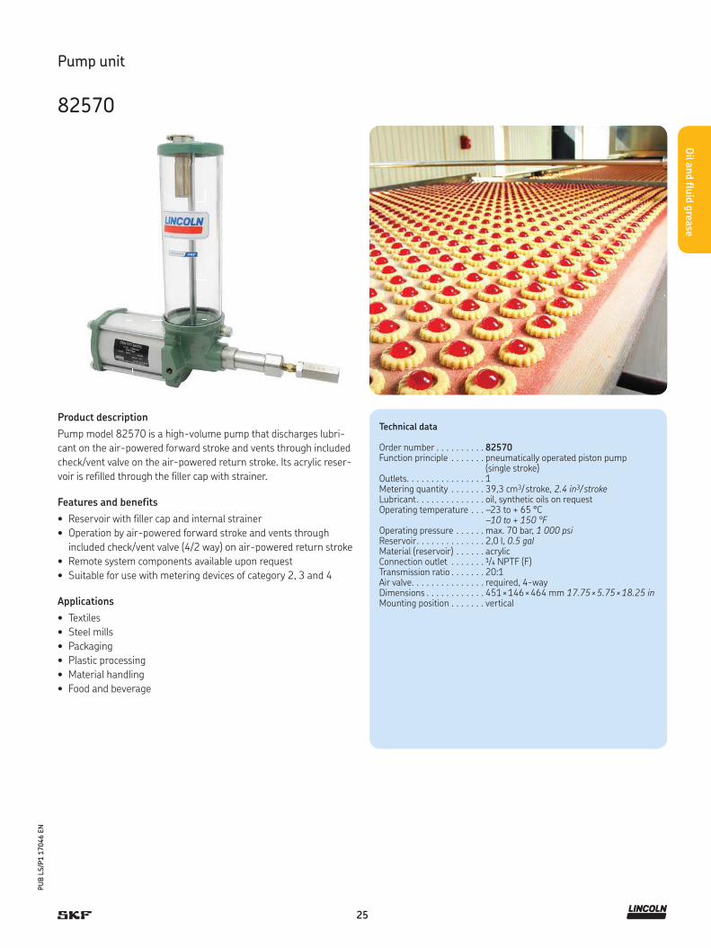
Order number . . . . . . . . . . 82570Function principle . . . . . . . pneumatically operated piston pump
(single stroke)Outlets. . . . . . . . . . . . . . . . 1Metering quantity . . . . . . . 39,3 cm3/ stroke, 2.4 in3/ strokeLubricant. . . . . . . . . . . . . . oil, synthetic oils on requestOperating temperature . . . –23 to + 65 °C
–10 to + 150 °F Operating pressure . . . . . . max. 70 bar, 1 000 psiReservoir. . . . . . . . . . . . . . 2,0 l, 0.5 galMaterial (reservoir) . . . . . . acrylicConnection outlet . . . . . . . 1/4 NPTF (F)Transmission ratio . . . . . . . 20:1Air valve. . . . . . . . . . . . . . . required, 4-wayDimensions . . . . . . . . . . . . 451 × 146 × 464 mm 17.75 × 5.75 × 18.25 inMounting position . . . . . . . vertical
Product description
Pump model 82570 is a high-volume pump that discharges lubri-
cant on the air-powered forward stroke and vents through included
check/vent valve on the air-powered return stroke. Its acrylic reser-
voir is refilled through the filler cap with strainer.
Features and benefits
• Reservoir with filler cap and internal strainer
• Operation by air-powered forward stroke and vents through
included check/vent valve (4/2 way) on air-powered return stroke
• Remote system components available upon request
• Suitable for use with metering devices of category 2, 3 and 4
Applications
• Textiles
• Steel mills
• Packaging
• Plastic processing
• Material handling
• Food and beverage
Pump unit
82570
26
PU
B L
S/P
1 1
7046 E
N
Oil a
nd flu
id g
rease
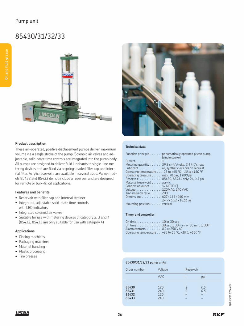
Product description
These air-operated, positive displacement pumps deliver maximum
volume via a single stroke of the pump. Solenoid air valves and ad-
justable, solid-state time controls are integrated into the pump body.
All pumps are designed to deliver fluid lubricants to single-line me-
tering devices and are filled via a spring-loaded filler cap and inter-
nal filter. Acrylic reservoirs are available in several sizes. Pump mod-
els 85432 and 85433 do not include a reservoir and are designed
for remote or bulk-fill oil applications.
Features and benefits
• Reservoir with filler cap and internal strainer
• Integrated, adjustable solid-state time controls
with LED indicators
• Integrated solenoid air valves
• Suitable for use with metering devices of category 2, 3 and 4
(85432, 85433 are only suitable for use with category 4)
Applications
• Closing machines
• Packaging machines
• Material handling
• Plastic processing
• Tire presses
Technical data
Function principle . . . . . . . pneumatically operated piston pump(single stroke)
Outlets. . . . . . . . . . . . . . . . 1Metering quantity . . . . . . . 39,3 cm3/ stroke, 2.4 in3/ strokeLubricant. . . . . . . . . . . . . . oil, synthetic oils oils on requestOperating temperature . . . –23 to +65 °C; –10 to +150 °FOperating pressure . . . . . . max. 70 bar, 1 000 psiReservoir. . . . . . . . . . . . . . 85430, 85431 only: 2 l, 0.5 galMaterial (reservoir) . . . . . . acrylicConnection outlet . . . . . . . 1/4 NPTF (F)Voltage . . . . . . . . . . . . . . . 120 V AC; 240 V ACTransmission ratio . . . . . . . 20:1Dimensions . . . . . . . . . . . . 627 × 166 × 460 mm
24.7 × 5.52 × 18.11 inMounting position . . . . . . . vertical
Timer and controller
On time . . . . . . . . . . . . . . . 10 or 30 secOff time . . . . . . . . . . . . . . . 30 sec to 30 min. or 30 min. to 30 hAlarm contacts . . . . . . . . . 8 A at 250 V ACOperating temperature . . . –23 to 65 °C; –10 to +150 °F
Pump unit
85430/31/32/33
85430/31/32/33 pump units
Order number Voltage Reservoir
V AC l gal
85430 120 2 0.585431 240 2 0.585432 120 – –85433 240 – –

27
PU
B L
S/P
1 1
7046 E
N
Oil a
nd flu
id g
rease
Product description
These pneumatically actuated piston pumps were designed for
intermittently operated, single-line centralized lubrication systems
with metering devices. The valve set required for pressure relief and
limitation is included.
Features and benefits
• Driven by on-board compressed air system
• Optional integrated control
• Electrical monitoring via external controller or SPS
• Simple handling
• Suitable for use with metering devices of category 1, 2 and 3
Applications
• Machine tool
• Printing machines
• Industrial assembly and automation
!NOTE
For further technical information, technical drawings,
accessories, spare parts or product function descriptions,
see the following publication available on
SKF.com/lubrication: 1-1110-EN, 951-170-012 EN
3D data and product configuration:
skf-lubrication.partcommunity.com/3d-cad-models/
Pump unit
PEF/PEU
Technical data
Function principle . . . . . . . pneumatically operated piston pumpOutlets. . . . . . . . . . . . . . . . 1Metering quantity . . . . . . . 48 or 50 cm 3/ stroke,
2.93 or 3.05 in3/ strokeLubricant. . . . . . . . . . . . . . mineral, synthetic, and environmentally
compatible oils, operating viscosity 20 to 1 500 mm²/s or fluid grease, NLGI 000, 00
Operating temperature . . . –25 to +80 °C; –13 to +176 °FOperating pressure . . . . . . max. 10 bar, 145 psiReservoir. . . . . . . . . . . . . . 3,0 l, 0.8 galMaterial (reservoir) . . . . . . polycarbonateConnection outlet . . . . . . . M 16 × 1,5DimensionsPEF-90 . . . . . . . . . . . . . . .
PEF-99 W . . . . . . . . . . . . .
PEU-99. . . . . . . . . . . . . . .
248 × 194 × 341 mm9.8 × 7.6 × 13.4 in 270 × 126 × 355 mm 10.6 × 4.9 × 13.9 in 270 × 126 × 355 mm 10.6 × 4.9 × 13.9 in
Mounting position . . . . . . . vertical
Fill-level switch for monitoring the minimum grease level
Type of contact . . . . . . . . . NO-contactSwitching voltage . . . . . . . max. 10 to 35 V DCOutput current. . . . . . . . . . 400 mACapacity. . . . . . . . . . . . . . . 15 mAType of enclosure. . . . . . . . IP 54
PEF/PEU pump units
Order numberLubricantOil Fluid grease
Fill-level switch
PEF-90 • • •PEF-99W – • •PEF-99W-S1 – • •PEF-99W-S2 – • •PEF-99W-S3 – • –PEU-99 • • –PEU-99-S2 • • –PEU-99-S3 • – –

28
PU
B L
S/P
1 1
7046 E
N
Oil a
nd flu
id g
rease
Product description
Pump model 283167 includes air motor, vent valve, translucent
reservoir with filler cap, strainer and 1 200 psi (82 bar) safety un-
loader. Pump is an oscillating positive displacement pump with
pneumatic drive. The change-over valve of the pump drive controls
reciprocating of the pump strokes (discharges oil to outlet on for-
ward stroke and sucks oil on back stroke). The reciprocating pump
operates under air pressure and as such discharges material until
the required system oil pressure is built up. The shut off and moni-
toring of the pump must be initiated by a pressure switch, 3/2 way
air valve, components to limit and adjust the air operating pressure.
These parts are to be furnished on site of the user.
Features and benefits
• Reservoir with filler cap and internal strainer
• Vent valve assembly enclosed
• Remote system components available upon request
• Suitable for use with metering devices of category 3 and 4
Applications
• Steel mills
• Glass manufacturing plants
• Packaging
• Plastic processing
• Material handling
• Food and beverage
• Metal cutting, metal forming
• Systems with many lubrication points
Technical data
Order number . . . . . . . . . . . . 283167Function principle . . . . . . . . . pneumatic, reciprocating piston pumpOutlets. . . . . . . . . . . . . . . . . . 1Metering quantity . . . . . . . . . 197 cm 3/ min, 12 in3/ minPump cycles/minute . . . . . . . max. 100 permittedLubricant. . . . . . . . . . . . . . . . oil, synthetic oils on requestOperating temperature . . . . . -23 to +65 °C
-10 to +150 °F Operating pressure . . . . . . . . max. 70 bar, 1 000 psiReservoir. . . . . . . . . . . . . . . . 7,1 l, 7 100 cm 3, 1.8 gal, 433 in3
Material (reservoir) . . . . . . . . acrylicAir inlet connection . . . . . . . . 1/8 NPTF (F)Connection outlet . . . . . . . . . 3/4 NPTF (F)Transmission ratio . . . . . . . . . 40:1Air valve . . . . . . . . . . . . . . . . required, 3-wayDimensions . . . . . . . . . . . . . . 591 × 229 × 413 mm
23.25 × 9 × 16.25 inMounting position . . . . . . . . . vertical
Pump unit
283167
Note: When operating the pump with air pressure > 1,7 bar a pressure switch for oil is required to limit the oil pressure (max. 68 bar) of the central lubrication system.

29
PU
B L
S/P
1 1
7046 E
N
Oil a
nd flu
id g
rease
Product description
Pump model 1826 is modular assembled and consists of air motor,
attached pump tube, vent valve assembly, drum cover, controller, lu-
bricant connecting hoses and safety unloader. Modular structured
air motor is fully pneumatically monitored. Supplied compressed air
to air motor moves oscillating piston in cylinder up and down.
Simultaneously outlet air pours out of opposite cylinder chamber via
exhausting baffle. A signal valve operates as a sensor and forwards
pneumatic signal pressure to a relay valve as soon as piston has
reached its fully stroke in one direction. Relay valve now switches
pneumatically movement of piston opposite. Oscillation operation
is working. Pumps consist in two devices, air motor and pump tube
with integrated shovel piston. Oscillation piston initiates shovel
piston to pump operation by sucking and pumping function. Pumps
are supplied in moduls must be furnished on side of user but can
also supplied completely on request.
Features and benefits
• Midsize volume PowerMaster air motor
• Carbon steel pump tube with shovel-foot design,
selected fit plunger and bushing
• Vent valve assembly and safety unloader included
• Drum cover for standard U.S. 55 gal. ( 200 l) drums
(removable head)
• Simplified, modular design
• Wear-resistant and robust construction, reliable
• Suitable for use with metering devices of category 2, 3 and 4
Applications
• Steel mills
• Plastic processing
• Food and beverage
• Glass industry
• Material handling
Technical data
Order number . . . . . . . . . . . . . . 1826Function principle . . . . . . . . . . . pneumatically operated
reciprocating piston pumpOutlets. . . . . . . . . . . . . . . . . . . . 1Metering quantity . . . . . . . . . . . 7 571 cm 3/ min, 462 in3/ minLubricant. . . . . . . . . . . . . . . . . . oil
Pump tube 84991Volume/cycle (up and down) . . . 100 cm³; 6.10 in³Max. pump cycles/minute . . . . . 70 permittedOperating temperature . . . . . . . +34 to +93 °C
-29 to +199 °FOperating pressure . . . . . . . . . . max. 70 bar; 1 000 psiAir inlet . . . . . . . . . . . . . . . . . . . 3/8 NPTF (F)Connection outlet . . . . . . . . . . . 3/4 NPTF (F)Transmission ratio . . . . . . . . . . . 24:1DimensionsTotal length . . . . . . . . . . . . . . . .Immersion length . . . . . . . . . . .
1 464 mm; 57.64 in864 mm; 34.01 in
Mounting position . . . . . . . . . . . vertical
Controller
Voltage . . . . . . . . . . . . . . . . . . . 110 V AC, 50 Hz; 120 V AC, 60 Hz
Pump unit
1826

30
PU
B L
S/P
1 1
7046 E
N
Oil a
nd flu
id g
rease
Product description
The Electric Cartridge Pump ECP was developed to lubricate
bearings and linear guides in small machines. It includes an inte-
grated pressure-relief. This electrically driven piston pump uses
24 V DC and is controlled by an external programmable logic con-
troller (PLC) for convenience. In addition, the pump is capable of
manually activating a lubrication cycle and can be used with an
optional, integrated level switch to monitor the oil level of the car-
tridge. Utilizing easy-to-exchange cartridges, it is compatible with
oil viscosities from 20 to 1 500 mm²/s and fluid grease grades
of NLGI 00 and 000.
Features and benefits
• Cost effective solution
• Simple to operate
• Increases reliability
• Minimizes risk of using wrong or contaminated lubricant
• Reduces unplanned downtime
• Extends maintenance intervals
• Minimizes environmental impact via
eficient use of lubricants
Applications
• Automation
• Machine tools
• Material handling
• Plastic processing
• Food and beverage
Technical data
Function principle . . . . . . . electrically operated piston pumpOutlets. . . . . . . . . . . . . . . . 2Metering quantity . . . . . . . fluid grease: 12 cm³/ min; 0.73 in³/ min
oil: 0,012 l/min; 0.0027 gal/minLubricant. . . . . . . . . . . . . . oil: 20 to 1 500 mm²/s
fluid grease: NLGI 00, 000 Operating temperature . . . +10 to +50 °C; 50 to 122 °FOperating pressure . . . . . . max. 38 bar; 550 psiReservoir. . . . . . . . . . . . . . 380 ml; 12.8 l. oz.Outlet connection . . . . . . . M10×1 thread or
SKF Quick Connector 6–8 mmOutput voltage. . . . . . . . . . 24 V DCDimensions . . . . . . . . . . . . without cartridge:
143×172×121 mm; 5.63×6.77×4.76 inwith cartridge:307,5×172×121 mm; 12.1×6.77×4.76 in
Mounting position . . . . . . . upright
Pump unit
ECP
!NOTE
For further technical information, technical drawings,
accessories, spare parts or product function descriptions,
see the following publication available on
SKF.com/lubrication: 16966 EN, 951-170-232
3D data and product configuration:
skf-lubrication.partcommunity.com/3d-cad-models/

31
PU
B L
S/P
1 1
7046 E
N
Oil a
nd flu
id g
rease
Order number configurator E C P 1 – 1 A
Pump type
ECP = Electric Cartridge Pump
Output volume
1 = 12 cm³/ min; 0.73 in³/ min 0,012 l/ min; 0.0027 gal/ min
Version
1 = 1st version
Reservoir level monitoring
W = Warning level (pre-warning empty)0 = No warning switch
Wall bracket
A = With standard bracket0 = Without
Electrical connection
A = Square plug following DIN EN 175301-803-A
Front outlet port connection
1 = Connection thread M10×12 = Quick connector ø 6 mm3 = Banjo fitting ø 6 mm4 = Quick connector ø 8 mmX = Closed
Outlet port bottom
1 = Connection thread M10×12 = Quick connector ø 6 mm3 = Banjo fitting ø 6 mm4 = Quick connector ø 8 mmX = Closed
Pump unit
ECP

32
PU
B L
S/P
1 1
7046 E
N
Oil a
nd flu
id g
rease
Product description
Suitable for multiple applications, the Lincoln P 653S electrically
driven oil pump simplifies the design of your lubrication system and
delivers significant flexibility. A member of the Centro-Matic family,
the pump comes complete with a reservoir, pressure switch/
transducer, vent valve and controller in one compact unit.
Features and benefits
• Integration of major system components
reduces labor and overall costs
• Simplifies lubrication system design
• Reduces installation time via “plug-and-go” capability
• Minimizes lubricant consumption by running only
when the machine is operating
Applications
• Automation
• Machine tools
• Glass manufacturing plants
• Woodworking facilities
• Oil and Gas plants
• Steel plants
!NOTE
For further technical information, technical drawings,
accessories, spare parts or product function descriptions,
see the following publication available on
SKF.com/lubrication: PUB LS/P2 16072 EN
Technical data
Function principle . . . . . . . electrically operated piston pumpOutlets. . . . . . . . . . . . . . . . 1Metering quantity . . . . . . . 24,6 cm 3/ min, 1.5 in3/ minLubricant. . . . . . . . . . . . . . oil, minimum 40 mm2/s (cST)Operating temperature . . . 0 to 50 °C; 32 to 122 °FOperating pressure . . . . . . with pressure switch: 240 bar, 3 500 psi
with pressure transducer: factory preset to 82 bar, 1 200 psi
Reservoir. . . . . . . . . . . . . . 4 l, 1 gal; 8 l, 2 galMaterial (reservoir) . . . . . . thermoplasticConnection outlet . . . . . . . G 1/4
Incoming voltage . . . . . . . . 120/230 V AC 1)
Current . . . . . . . . . . . . . . . max. 1,7 AFrequency . . . . . . . . . . . . . 47 to 63 HzPause time . . . . . . . . . . . . max. 59 h, 59 min
min. 4 min;Pause time increments . . . 1 hr or 1 minMinimum pause time . . . . 4 minMaximum pause time . . . . 59 h. 59 minPumping time . . . . . . . . . . max. 12 minDimensions . . . . . . . . . . . . depending on model
min. 240 × 467 × 235 mmmax. 240 × 508 × 235 mmmin. 9.5 × 18.4 × 9.25 inmax. 9.5 × 20 × 9.25 in
Mounting position . . . . . . . upright
Pump elements
Piston . . . . . . . . . . . . . . . . ø 7 mm, 0.3 inNumber connected . . . . . . 3Protection . . . . . . . . . . . . . 1P 6K9K
Pump unit
P 653S (oil)
1) 24 V DC version available on request.

33
PU
B L
S/P
1 1
7046 E
N
Oil a
nd flu
id g
rease
P653S (oil)
Order number 120/230 V AC50/60 Hz
Reservoir capacity
Internal pressure switch
Internal pressure transducer
Internal and end-of-line pressure switch
Internal and end-of-line pressure transducer
l gal
80127 • 4 1 • • – –80128 • 8 2 • • – –
Pump unit
P 653S (oil)

34
PU
B L
S/P
1 1
7046 E
N
Oil a
nd flu
id g
rease
Product description
Used with SKF single-line systems, the KFB series gear pump units
supply fluid grease NLGI 000 and 00 and include a pressure-relief
valve and a pressure-limiting valve. The pumps are designed for
supply voltages of 12 V DC and 24 V DC and are controlled either by
an integrated electronic control unit or externally, via the machine
control system. Depending on the design, the gear pump units are
filled via a filler socket or attached filler coupling.
Features and benefits
• Compact pump unit
• Integrated pressure-relief valve and pressure-regulating valve
• Visual or optional electrical fill-level monitoring
• Optional integrated control
• Optional pre-assembled lubrication distributor of VN series
Applications
• Commercial vehicles
• Industrial applications
!NOTE
For further technical information, technical drawings,
accessories, spare parts or product function descriptions,
see the following publication available on
SKF.com/lubrication: 1-1206-EN, 951-170-009 EN
Technical data
Function principle . . . . . . . . . electrically operated gear pumpOutlets. . . . . . . . . . . . . . . . . . 1Metering quantity1) . . . . . . . . 50 cm³/ min, 3.05 in3/ minLubricant. . . . . . . . . . . . . . . . fluid grease of NLGI 000 or 00Operating temperature . . . . . –25 to +75 °C; –13 to +167 °FOperating pressure . . . . . . . . max. 38 bar, 550 psiReservoir. . . . . . . . . . . . . . . . KFB(S)1-W: 1 l, 0.26 gal
KFB(S)1: 1,4 l, 0.37 galMaterial (reservoir) . . . . . . . . translucent plasticConnection outlet . . . . . . . . . ø 10 × 1.5
(max. 16 m, 52.5 ft)Dimensions:KFB(S)1, KFB(S)1-W. . . . . . .
KFB(S)1-4-S1, KFB(S)1-W-4-S1, KFB(S)1-6-S1, KFB(S)1-W-6-S1 . . . . . . . . .
216 × 150 × 235 mm 8.5 × 5.9 × 9.3 in
245 × 150 × 294 mm 9.6 × 5.9 × 11.6 in
Mounting position . . . . . . . . . vertical
DC motorVoltage . . . . . . . . . . . . . . . . . 12, 24 V DCCurrent . . . . . . . . . . . . . . . . . 3,8 A; 1,7 ARated output . . . . . . . . . . . . . 46 W, 41 WProtection class . . . . . . . . . . . IP 6K6K / IP 6K9K
Pump unit
KFB
1) At back pressure of 10 bar (145 psi) and a temperature of +25 °C (+77 °F)

35
PU
B L
S/P
1 1
7046 E
N
Oil a
nd flu
id g
rease
Pump unit
KFB
KFB pump units
Order number.
LubricantFluid greaseNLGI 000, 00
Control unit
Fill-level switch
Electrical connectionsCircular connectorAMP, 4-pin
Circular connectorAMP, 7-pin Design
KFB1 2) • – – • – Basic versionKFB1-W 2) • – • – • Basic versionKFBS1 2) • • – – • Basic versionKFBS1-W 2) • • • – • Basic version
KFB1-4-S1 2) • – – • – VN metering device, 4-outletsKFBS1-4-S1 2) • • – – • VN metering device, 4-outletsKFB1-6-S1 2) • – – • – VN metering device, 6-outletsKFBS1-6-S1 2) • • – – • VN metering device, 6-outlets
KFB1-W-4-S1 2) • – • – • VN metering device, 4-outletsKFBS1-W-4-S1 2) • • • – • VN metering device, 4-outletsKFB1-W-6-S1 2) • – • – • VN metering device, 6-outletsKFBS1-W-6-S1 2) • • • – • VN metering device, 6-outlets
1) All units for vehicle applications have type approval pursuant to ECE-R 10.2) When ordering, quote the code for voltage to be used
12 V DC: Order code +91224 V DC: Order code +924
For units KFB(S)1, KFB(S)1-W, KFB(S)1-4-S1, KFB(S)1-W-4-S1,KFB(S)1-6-S1, KFB(S)1-W-6-S1
Fill-level switch (for KFB(S)1-W) opens when fill level too low
Switching voltage . . . . . . . . . . . . . . . . . . . . 10 to 36 V DCSwitching current . . . . . . . . . . . . . . . . . . . . resistive load1): ≤0.5 ASwitching capacity . . . . . . . . . . . . . . . . . . . . resistive load1): ≤12 W
Relubrication metering device VN (KFB(S)1(-W)4-S1, KFB(S)1(-W)-6-S1)
Lubrication point connection . . . . . . . . . . . . Push-to-connect fitting for tube ø 4
Metering quantity . . . . . . . . . . . . . . . . . . . . 0.1; 0.2; 0.4 cm³Feeder body. . . . . . . . . . . . . . . . . . . . . . . . . Die-cast zinc, black
corrosion protection
Control unit IG502-2-I (KFBS1)Interval, adjustable . . . . . . . . . . . . . . . . . . . 0.1 ... 99.9 hPump run time, adjustable . . . . . . . . . . . . . 0.1 ... 99.9 minMax. pump run time . . . . . . . . . . . . . . . . . . 3.0 min2)
Elapsed-hours counter . . . . . . . . . . . . . . . . 0 ... 99999.9 hFault-hours counter . . . . . . . . . . . . . . . . . . 0 ... 99999.9 h
Additional input power for units with control unit (without output load). . . . . 4 W
1) When switching inductive loads, take appropriate measures to protect contacts2) The operating mode S3 (periodic duty) describes the ratio of pump run time to subsequent
down time. If the relative ON-time is 2.5% and the duty cycle time is 10 to 120 min., then the limit values are as follows: Min. duty cycle time: 10 min×0.025 = 0.25 min. pump run time with subsequent down time of 9.75 min.Max. duty cycle time: 120 min×0.025 = 3 min. pump run time with subsequent down time of 117 min.
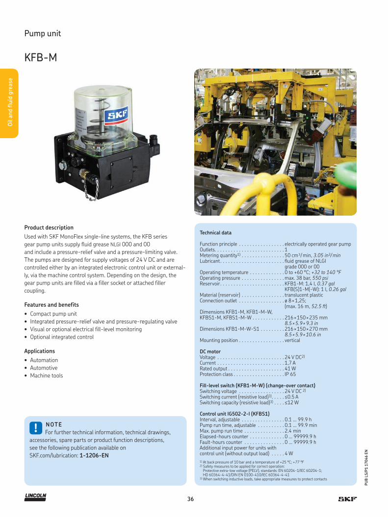
36
PU
B L
S/P
1 1
7046 E
N
Oil a
nd flu
id g
rease
Pump unit
KFB-M
1) At back pressure of 10 bar and a temperature of +25 °C; +77 °F2) Safety measures to be applied for correct operation:
Protective extra-low voltage (PELV), standards: EN 60204-1/IEC 60204-1; HD 60364-4-41/DIN EN 0100-410/IEC 60364-4-41
3) When switching inductive loads, take appropriate measures to protect contacts
Technical data
Function principle . . . . . . . . . . . . . . . . . electrically operated gear pumpOutlets. . . . . . . . . . . . . . . . . . . . . . . . . . 1Metering quantity1) . . . . . . . . . . . . . . . . 50 cm³/ min, 3.05 in3/ minLubricant. . . . . . . . . . . . . . . . . . . . . . . . fluid grease of NLGI
grade 000 or 00Operating temperature . . . . . . . . . . . . . 0 to +60 °C; +32 to 140 °FOperating pressure . . . . . . . . . . . . . . . . max. 38 bar, 550 psiReservoir. . . . . . . . . . . . . . . . . . . . . . . . KFB1-M: 1,4 l, 0.37 gal
KFB(S)1-M(-W): 1 l, 0.26 galMaterial (reservoir) . . . . . . . . . . . . . . . . translucent plasticConnection outlet . . . . . . . . . . . . . . . . . ø 8 × 1,25;
(max. 16 m, 52.5 ft)Dimensions KFB1-M, KFB1-M-W, KFBS1-M, KFBS1-M-W . . . . . . . . . . . .
Dimensions KFB1-M-W-S1 . . . . . . . . .
216 × 150 × 235 mm 8.5 × 5.9 × 9.3 in 216 × 150 × 270 mm 8.5 × 5.9 × 10.6 in
Mounting position . . . . . . . . . . . . . . . . . vertical
DC motorVoltage . . . . . . . . . . . . . . . . . . . . . . . . . 24 V DC2)
Current . . . . . . . . . . . . . . . . . . . . . . . . . 1,7 ARated output . . . . . . . . . . . . . . . . . . . . . 41 WProtection class . . . . . . . . . . . . . . . . . . . IP 65
Fill-level switch (KFB1-M-W) (change-over contact)Switching voltage . . . . . . . . . . . . . . . . . 24 V DC 2)
Switching current (resistive load)3). . . . . ≤0.5 ASwitching capacity (resistive load)3) . . . . ≤12 W
Control unit IG502-2-I (KFBS1)Interval, adjustable . . . . . . . . . . . . . . . . 0.1 ... 99.9 hPump run time, adjustable . . . . . . . . . . 0.1 ... 99.9 minMax. pump run time . . . . . . . . . . . . . . . 2.4 minElapsed-hours counter . . . . . . . . . . . . . 0 ... 99999.9 hFault-hours counter . . . . . . . . . . . . . . . 0 ... 99999.9 hAdditional input power for units with control unit (without output load) . . . . . 4 W
Product description
Used with SKF MonoFlex single-line systems, the KFB series
gear pump units supply fluid grease NLGI 000 and 00
and include a pressure-relief valve and a pressure-limiting valve.
The pumps are designed for supply voltages of 24 V DC and are
controlled either by an integrated electronic control unit or external-
ly, via the machine control system. Depending on the design, the
gear pump units are filled via a filler socket or attached filler
coupling.
Features and benefits
• Compact pump unit
• Integrated pressure-relief valve and pressure-regulating valve
• Visual or optional electrical fill-level monitoring
• Optional integrated control
Applications
• Automation
• Automotive
• Machine tools
!NOTE
For further technical information, technical drawings,
accessories, spare parts or product function descriptions,
see the following publication available on
SKF.com/lubrication: 1-1206-EN
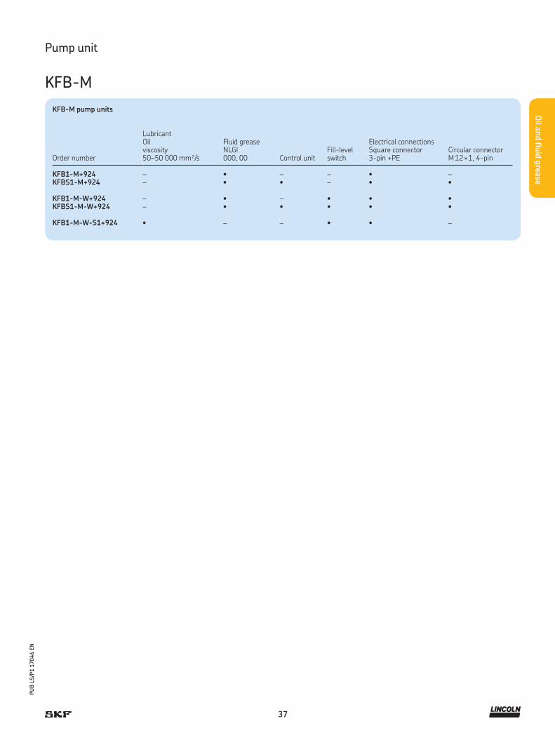
37
PU
B L
S/P
1 1
7046 E
N
Oil a
nd flu
id g
rease
Pump unit
KFB-M
KFB-M pump units
Order number
Lubricant Oil viscosity50–50 000 mm²/s
Fluid greaseNLGI 000, 00 Control unit
Fill-level switch
Electrical connectionsSquare connector3-pin +PE
Circular connectorM 12 × 1, 4-pin
KFB1-M+924 – • – – • –KFBS1-M+924 – • • – • •
KFB1-M-W+924 – • – • • •KFBS1-M-W+924 – • • • • •
KFB1-M-W-S1+924 • – – • • –
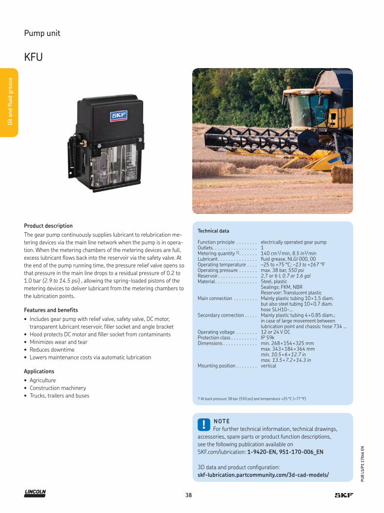
38
PU
B L
S/P
1 1
7046 E
N
Oil a
nd flu
id g
rease
Product description
The gear pump continuously supplies lubricant to relubrication me-
tering devices via the main line network when the pump is in opera-
tion. When the metering chambers of the metering devices are full,
excess lubricant flows back into the reservoir via the safety valve. At
the end of the pump running time, the pressure relief valve opens so
that pressure in the main line drops to a residual pressure of 0.2 to
1.0 bar (2.9 to 14.5 psi) , allowing the spring-loaded pistons of the
metering devices to deliver lubricant from the metering chambers to
the lubrication points.
Features and benefits
• Includes gear pump with relief valve, safety valve, DC motor,
transparent lubricant reservoir, filler socket and angle bracket
• Hood protects DC motor and filler socket from contaminants
• Minimizes wear and tear
• Reduces downtime
• Lowers maintenance costs via automatic lubrication
Applications
• Agriculture
• Construction machinery
• Trucks, trailers and buses
!NOTE
For further technical information, technical drawings,
accessories, spare parts or product function descriptions,
see the following publication available on
SKF.com/lubrication: 1-9420-EN, 951-170-006_EN
3D data and product configuration:
skf-lubrication.partcommunity.com/3d-cad-models/
Technical data
Function principle . . . . . . . . electrically operated gear pumpOutlets. . . . . . . . . . . . . . . . . 1Metering quantity 1) . . . . . . . 140 cm³/ min, 8.5 in3/ minLubricant. . . . . . . . . . . . . . . fluid grease, NLGI 000, 00Operating temperature . . . . –25 to +75 °C; –13 to +167 °FOperating pressure . . . . . . . max. 38 bar, 550 psiReservoir. . . . . . . . . . . . . . . 2,7 or 6 l; 0.7 or 1.6 galMaterial . . . . . . . . . . . . . . . . Steel, plastic
Sealings: FKM, NBRReservoir: Translucent plastic
Main connection . . . . . . . . . Mainly plastic tubing 10 × 1.5 diam.but also steel tubing 10 × 0.7 diam. hose SLH10-...
Secondary connection . . . . . Mainly plastic tubing 4 × 0.85 diam.; in case of large movement between lubrication point and chassis: hose 734 …
Operating voltage . . . . . . . . 12 or 24 V DCProtection class . . . . . . . . . . IP 59kDimensions . . . . . . . . . . . . . min. 268 × 154 × 325 mm
max. 343 × 184 × 364 mmmin. 10.5 × 6 × 12.7 inmax. 13.5 × 7.2 × 14.3 in
Mounting position . . . . . . . . vertical
Pump unit
KFU
1) At back pressure 38 bar (550 psi) and temperature +25 °C (+77 °F)

39
PU
B L
S/P
1 1
7046 E
N
Oil a
nd flu
id g
rease
KFU pump units
Order number Reservoir Operating voltage
l gal V DC Amp
KFU2-40+912 2,7 12 12 7.5KFU2-40+924 2,7 12 24 7.5KFU6-20+912 1) 6 1.6 12 7.5KFU6-20+924 1) 6 1.6 24 7.5KFUS2-64+912 2,7 12 12 16KFUS2-64+924 2,7 12 24 8
1) This unit should only be used for systems with a minimum lubricant consumption of 6 l (1.6 gal) per year.
Pump unit
KFU

40
PU
B L
S/P
1 1
7046 E
N
Oil a
nd flu
id g
rease
Product description
MKU gear pump units are used in single-line systems and include a
pre-installed pressure-regulating valve and pressure-relief valve.
These units can be supplied with an optional pressure gauge for vis-
ual monitoring of pressure changes in the main line. Electrical pres-
sure monitoring is performed by an integrated pressure switch, and
fill-level monitoring also is possible. The pump units are controlled
externally via the machine control system or an integrated control
unit. Also, MKU units can be supplied with a pushbutton to activate
interim lubrication at any time. Main functions are integrated into
the lid, and a plastic cap protects the electrical components from
contaminants such as dirt and dust.
Features and benefits
• Integrated pressure limitation and pressure relief valve
• Optional: electrical pressure switch, pressure gauge, float switch
• External control via SPS or by means of
internal control unit possible
• All important functions integrated into the lid
• Modular construction
Applications
• Material handling
• Automotive
• Machine tool
• Printing and finishing
• Industrial assembly and automation
• Textiles!
NOTE
For further technical information, technical drawings,
accessories, spare parts or product function descriptions,
see the following publication available on
SKF.com/lubrication: 1-1203-EN, 951-170-005 EN
3D data and product configuration:
skf-lubrication.partcommunity.com/3d-cad-models/
Technical data
Function principle . . . . . . . . . . electrically operated gear pumpMetering quantity . . . . . . . . . . 100; 200; 500 cm³/ min
6; 12; 31 in³/ minLubricant . . . . . . . . . . . . . . . . mineral oil or synthetic oil,
20 to 1 500 mm2/sOperating temperature . . . . . . +10 to 40 °C; +50 to 104 °FOperating pressure . . . . . . . . . max. 30 bar, 435 psiReservoir . . . . . . . . . . . . . . . . 2,0; 3,0 and 6,0 l, 0.5, 0.8 and 1.6 galMaterial (reservoir) . . . . . . . . . plastic, metalConnection outlet . . . . . . . . . . G 1/4
Protection class . . . . . . . . . . . IP 54Dimensions pump unit with 2 l; 0.5 gal plastic reservoir. . .
3 l; 0.8 gal plastic reservoir . .
3 l; 0.8 gal metal reservoir . . .
6 l; 1,5 gal plastic reservoir. . .
204 × 130 × 298 mm 8 × 5.2 × 11.7 in286 × 132 × 298 mm 11.3 × 5.2 × 11.7 in 286 × 132 × 313 mm 11.3 × 5.2 × 12.3 in290 × 178 × 334 mm 11.4 × 7 × 13.2 in
Mounting position . . . . . . . . . vertical
Pump unit
MKU
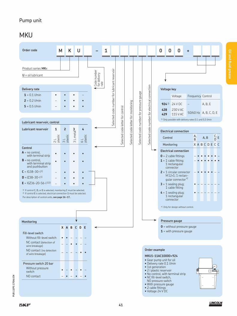
41
PU
B L
S/P
1 1
7046 E
N
Oil a
nd flu
id g
rease
Pump unit
MKU
Order code M K U – 1 0 0 0 +
Product series MKx
U = oil lubricant
Delivery rate
1 = 0.1 l/min • • • –
2 = 0.2 l/min – • • •
5 = 0.5 l/min – • • •
Voltage key
Voltage Frequency Control
9243) 24 V DC – A, B, E
428 230 V AC50/60 Hz A, B, C, D, E
429 115 V AC
3) Only possible with delivery rates 0.1 und 0.2 l/min
Sel
ecte
d c
ode
num
ber
for
lubri
cant re
serv
oir
Sel
ecte
d c
ode
lett
er fo
r co
ntr
ol
Sel
ecte
d c
ode
lett
er fo
r m
onitor
ing
Sel
ecte
d c
ode
num
ber
for
pre
ssure
gau
ge
Sel
ecte
d c
ode
num
ber
for
elec
tric
al c
onnec
tion
Monitoring
X A B C D E
Fill-level switch
Without fill-level switch • • – – – –
NC contact (detection of wire breakage)
– – • • – –
NO contact (no detection of wire breakage)
– – – – • •
Pressure switch 20 bar
Without pressure switch
• – • – • –
NO contact – • – • – •
Code
num
ber
for
deliv
ery
rate
Lubricant reservoir, control
Lubricant reservoir 1 2 3 4
2 l,
pla
stic
3 l,
pla
stic
3 l,
met
al
6 l,
pla
stic
Control
A = no control, with terminal strip
• • • •
B = no control, with terminal strip and pushbutton
• • • •
C = IG38-30-I1) – • • •
D = IZ38-30-I1) – • • •
E = IGZ36-20-S6-I1)2) – • • •
1) If control C, D, or E is selected, monitoring C must be selected. 2) If control E is selected, electrical connection 1 must be selected.
For description of control units, see page 16–17.
Electrical connection
ControlA, B
A, BC, D
E
Monitoring X A B C D E C C
Electrical connection
0 = 2 cable fittings – • • • • • • –
1 = 1 cable fitting; 1 rectangularconnector
– • • • • • • •
2 = 1 circular connector M 12×1; 1 rectan- gular connector4)
– • • • • • – –
3 = 1 sealing plug;1 cable fitting
• – – – – – – –
4 = 1 sealing plug; 1 rectangular connector
• – – – – – – –
4) Only for design without control.
Pressure gauge
0 = without pressure gauge
1 = with pressure gauge
Order example
MKU1-11AC10000+924
• Gear pump unit for oil • Delivery rate 0.1 l/min• 1st generation• 2 l plastic reservoir• No control, with terminal strip• NC fill-level switch,
NO pressure switch• With pressure gauge• 2 cable fittings• Voltage 24 V DC
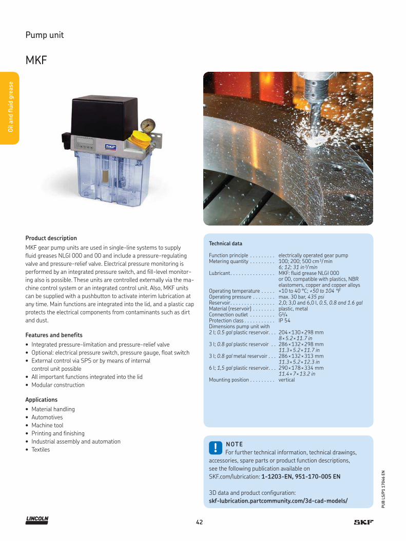
42
PU
B L
S/P
1 1
7046 E
N
Oil a
nd flu
id g
rease
Product description
MKF gear pump units are used in single-line systems to supply
fluid greases NLGI 000 and 00 and include a pressure-regulating
valve and pressure-relief valve. Electrical pressure monitoring is
performed by an integrated pressure switch, and fill-level monitor-
ing also is possible. These units are controlled externally via the ma-
chine control system or an integrated control unit. Also, MKF units
can be supplied with a pushbutton to activate interim lubrication at
any time. Main functions are integrated into the lid, and a plastic cap
protects the electrical components from contaminants such as dirt
and dust.
Features and benefits
• Integrated pressure-limitation and pressure-relief valve
• Optional: electrical pressure switch, pressure gauge, float switch
• External control via SPS or by means of internal
control unit possible
• All important functions integrated into the lid
• Modular construction
Applications
• Material handling
• Automotives
• Machine tool
• Printing and finishing
• Industrial assembly and automation
• Textiles !NOTE
For further technical information, technical drawings,
accessories, spare parts or product function descriptions,
see the following publication available on
SKF.com/lubrication: 1-1203-EN, 951-170-005 EN
3D data and product configuration:
skf-lubrication.partcommunity.com/3d-cad-models/
Technical data
Function principle . . . . . . . . . electrically operated gear pumpMetering quantity . . . . . . . . . 100; 200; 500 cm³/ min
6; 12; 31 in³/ minLubricant. . . . . . . . . . . . . . . . MKF: fluid grease NLGI 000
or 00, compatible with plastics, NBRelastomers, copper and copper alloys
Operating temperature . . . . . +10 to 40 °C; +50 to 104 °FOperating pressure . . . . . . . . max. 30 bar, 435 psiReservoir. . . . . . . . . . . . . . . . 2,0; 3,0 and 6,0 l, 0.5, 0.8 and 1.6 galMaterial (reservoir) . . . . . . . . plastic, metalConnection outlet . . . . . . . . . G1/4
Protection class . . . . . . . . . . . IP 54Dimensions pump unit with 2 l; 0.5 gal plastic reservoir. . .
3 l; 0.8 gal plastic reservoir . .
3 l; 0.8 gal metal reservoir . . .
6 l; 1,5 gal plastic reservoir. . .
204 × 130 × 298 mm 8 × 5.2 × 11.7 in286 × 132 × 298 mm 11.3 × 5.2 × 11.7 in 286 × 132 × 313 mm 11.3 × 5.2 × 12.3 in290 × 178 × 334 mm 11.4 × 7 × 13.2 in
Mounting position . . . . . . . . . vertical
Pump unit
MKF

43
PU
B L
S/P
1 1
7046 E
N
Oil a
nd flu
id g
rease
Pump unit
MKF
Voltage key
Voltage Frequency Control
924 24 V DC – A, B, E
428 230 V AC50/60 Hz A, B, C, D, E
429 115 V AC
Sel
ecte
d c
ode
lett
er fo
r co
ntr
ol
Sel
ecte
d c
ode
lett
er fo
r m
onitor
ing
Sel
ecte
d c
ode
num
ber
for
pre
ssure
gau
ge
Sel
ecte
d c
ode
num
ber
for
elec
tric
al c
onnec
tion
Order code M K F – 1 0 0 0 +
Product series MK
F = fluid grease lubricant
Sel
ecte
d c
ode
num
ber
for
lubri
cant re
serv
oir
Cod
e num
ber
for
deliv
ery
rate
Delivery rate
1 = 0.1 l/min • • –
2 = 0.2 l/min – • •
Monitoring
X A B C
Fill-level switch
Without fill-level switch • • – –
NC contact (detection of wire breakage)
– – • •
NO contact (no detection of wire breakage)
– – – –
Pressure switch 20 bar
Without pressure switch • – • –
NO contact – • – •
Lubricant reservoir, control
Lubricant reservoir 1 2 4
2 l,
pla
stic
3 l,
pla
stic
6 l,
pla
stic
Control
A = no control, with terminal strip
• • •
B = no control, with terminal strip and pushbutton
• • •
C = IG38-30-I1) – • •
D = IZ38-30-I1) – • •
E = IGZ36-20-S6-I1)2) – • •
1) If control C, D, or E is selected, monitoring C must be selected. 2) If control E is selected, electrical connection 1 must be selected.
For description of control units, see page 16–17.
Order example
MKF1-11AC10000+924
• Gear pump unit for fluid grease • Delivery rate 0.1 l/min• 1st generation• 2 l plastic reservoir• No control, with terminal strip• NC fill level switch,
NO pressure switch• With pressure gauge• 2 cable fittings• Voltage 24 V DC
Electrical connection
ControlA, B
A, BC, D
E
Monitoring X A B C C C
Electrical connection
0 = 2 cable fittings – • • • • –
1 = 1 cable fitting; 1 rectangularconnector
– • • • • •
2 = 1 circular connector M 12×1; 1 rectan- gular connector4)
– • • • – –
3 = 1 sealing plug;1 cable fitting
• – – – – –
4 = 1 sealing plug; 1 rectangular connector
• – – – – –
4) Only for design without control.
Pressure gauge
0 = without pressure gauge
1 = with pressure gauge

44
PU
B L
S/P
1 1
7046 E
N
Oil a
nd flu
id g
rease
Product description
The gear pump units comprising the MFE series are designed to
supply lubricant used in intermittently operated, single-line central-
ized lubrication systems. The basic setup includes a gear pump unit
with motor, a 3- or 6 l lubricant reservoir in metal or plastic, or
a 15 l metal reservoir and float switch to monitor the minimum
permissible level of lubricant. In addition to the basic models,
units can be outfitted with add-ons.
Features and benefits
• Integrated float switch for fill-level monitoring
• Integrated pressure-relief valve and pressure-regulating valve
• Motors available for various voltage ranges and approvals
• Special designs offered for a wide range of applications
• Suitable for intermittent operation
• For remote installation out of reservoir or for built-in reservoir
• Reliable and versatile
• Suitable for use with metering devices of category 1 and 2
Applications
• Automotive manufacturing
• Metal, including presses
• Machine tools
• Printing and finishing
• Industrial assembly and automation
!NOTE
For further technical information, technical drawings,
accessories, spare parts or product function descriptions,
see the following publication available on
SKF.com/lubrication: 1-1202-EN, 951-170-002 EN
Technical data
Function principle . . . . . . . . .electrically operated gear pumpOutlets. . . . . . . . . . . . . . . . . .1Metering quantity . . . . . . . . .250 to 500 cm³/ min, 15 to 31 in³/ minLubricant. . . . . . . . . . . . . . . .oil 5 to 2 000 mm²/s and fluid grease
NLGI 00, 000Operating temperature . . . . .–10 to +60 °C; +14 to +140 °FBack pressure . . . . . . . . . . . .max. 17,5; 28 bar,
max. 255, 405 psiReservoir. . . . . . . . . . . . . . . .3; 6; 15 l, 0.8, 1.6, 4 galMaterial (reservoir) . . . . . . . .plastic, metalConnection outlet . . . . . . . . .M 14×1.5Dimensions pump unit with 3 l; 0.8 gal plastic reservoir . .3 l; 0.8 gal metal reservoir. . .6 l; 1,5 gal plastic reservoir . .6 l; 1,5 gal metal reservoir. . .15 l; 4 gal metal reservoir . . .
303 × 130 × 245 mm; 11.9 × 5.1 × 9.6 in 332 × 178 × 312 mm; 13 × 7 × 12.3 in319 × 128 × 265 mm; 12.6 × 5 × 10.4 in370 × 167 × 330 mm; 14.6 × 6.6 × 12.9 in453 × 200 × 436 mm; 17.8 × 7.8 × 17.2 in
Mounting position . . . . . . . . .vertical
Floating switch for low-level monitoring of oil
Type of contact . . . . . . . . . . .1 change-over; 2 change-over contacts (reed contacts)
Switching voltage . . . . . . . . .max. 230 V AC, 230 V DCSwitching current . . . . . . . . .max. 0,8 A; 1,0 A
Switching capacity . . . . . . . . .max. 60 VA, 40 W1)
Type of enclosure. . . . . . . . . . IP 65
Pump unit
MFE
1) Take appropriate measures to protect contacts when switching inductive loads
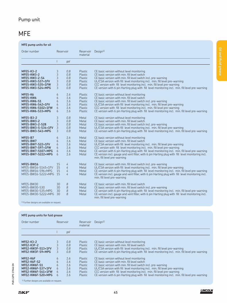
45
PU
B L
S/P
1 1
7046 E
N
Oil a
nd flu
id g
rease
Pump unit
MFE
MFE pump units for oil
Order number Reservoir Reservoir material
Design1)
l gal
MFE5-K3-2 3 0.8 Plastic CE basic version without level monitoringMFE5-KW3-2 3 0.8 Plastic CE basic version with min. fill level switchMFE5-KW3-2-S4 3 0.8 Plastic CE basic version with min. fill level switch incl. pre-warningMFE5-KW3-S37+1FV 3 0.8 Plastic UL/CSA version with fill level monitoring incl. min. fill level pre-warningMFE5-KW3-S35+1FW 3 0.8 Plastic CCC version with fill level monitoring incl. min. fill level pre-warningMFE5-KW3-S24+MPG 3 0.8 Plastic CE version with 6 pin Harting plug with fill level monitoring incl. min. fill level pre-warning
MFE5-K6 6 1.6 Plastic CE basic version without level monitoringMFE5-KW6 6 1.6 Plastic CE basic version with min. fill level switchMFE5-KW6-S1 6 1.6 Plastic CE basic version with min. fill level switch incl. pre-warningMFE5-KW6-S42+1FV 6 1.6 Plastic UL/CSA version with fill level monitoring incl. min. fill level pre-warningMFE5-KW6-S102+1FW 6 1.6 Plastic CCC version with fill level monitoring incl. min. fill level pre-warningMFE5-KW6-S33+MPG 6 1.6 Plastic CE version with 6 pin Harting plug with fill level monitoring incl. min. fill level pre-warning
MFE5-B3-2 3 0.8 Metal CE basic version without level monitoringMFE5-BW3-2 3 0.8 Metal CE basic version with min. fill level switchMFE5-BW3-2-S28 3 0.8 Metal CE basic version with min. fill level switch incl. pre-warningMFE5-BW3-S-S34+1FV 3 0.8 Metal UL/CSA version with fill level monitoring incl. min. fill level pre-warningMFE5-BW3-S41+MPG 3 0.8 Metal CE version with 6 pin Harting plug with fill level monitoring incl. min. fill level pre-warning
MFE5-B7 6 1.6 Metal CE basic version without level monitoringMFE5-BW7 6 1.6 Metal CE basic version with min. fill level switchMFE5-BW7-S22+1FV 6 1.6 Metal UL/CSA version with fill level monitoring incl. min. fill level pre-warningMFE5-BW7-S97+1FW 6 1.6 Metal CCC version with fill level monitoring incl. min. fill level pre-warningMFE5-BW7-S107+MPG 6 1.6 Metal CE version with 6 pin Harting plug with fill level monitoring incl. min. fill level pre-warningMFE5-BW7-S222+MPG 6 1.6 Metal CE version incl. gauge and vent filter, with 6 pin Harting plug with fill level monitoring incl.
min. fill level pre-warning
MFE5-BW16 15 4 Metal CE basic version with min. fill level switch incl. pre-warningMFE5-BW16-S145+1FV 15 4 Metal UL/CSA version with fill level monitoring incl. min. fill level pre-warningMFE5-BW16-S96+MPG 15 4 Metal CE version with 6 pin Harting plug with fill level monitoring incl. min. fill level pre-warningMFE5-BW16-S222+MPG 15 4 Metal CE version incl. gauge and vent filter, with 6 pin Harting plug with fill level monitoring incl.
min. fill level pre-warning
MFE5-BW30 30 8 Metal CE basic version with min. fill level switchMFE5-BW30-S30 30 8 Metal CE basic version with min. fill level switch incl. pre-warningMFE5-BW30-S35+MPG 30 8 Metal CE version with 6 pin Harting plug with fill level monitoring incl. min. fill level pre-warningMFE5-BW30-S222+MPG 30 8 Metal CE version incl. gauge and vent filter, with 6 pin Harting plug with fill level monitoring incl.
min. fill level pre-warning
MFE pump units for fuid grease
Order number Reservoir Reservoir material
Design1)
l gal
MFE2-K3-2 3 0.8 Plastic CE basic version without level monitoringMFE2-K3F-2 3 0.8 Plastic CE basic version with min. fill level switchMFE2-KW3F-S13+1FV 3 0.8 Plastic UL/CSA version with fill level monitoring incl. min. fill level pre-warningMFE2-KW3F-S9+MPG 3 0.8 Plastic CE version with 6 pin Harting plug with fill level monitoring incl. min. fill level pre-warning
MFE2-K6F 6 1.6 Plastic CE basic version without level monitoringMFE2-K6F-S2 6 1.6 Plastic CE basic version with min. fill level switchMFE2-KW6F-S1 6 1.6 Plastic CE basic version with min. fill level switch incl. pre-warningMFE2-KW6F-S37+1FV 6 1.6 Plastic UL/CSA version with fill level monitoring incl. min. fill level pre-warningMFE2-KW6F-S41+1FW 6 1.6 Plastic CCC version with fill level monitoring incl. min. fill level pre-warningMFE2-KW6F-S20+MPG 6 1.6 Plastic CE version with 6 pin Harting plug with fill level monitoring incl. min. fill level pre-warning
1) Further designs are available on request.
1) Further designs are available on request.
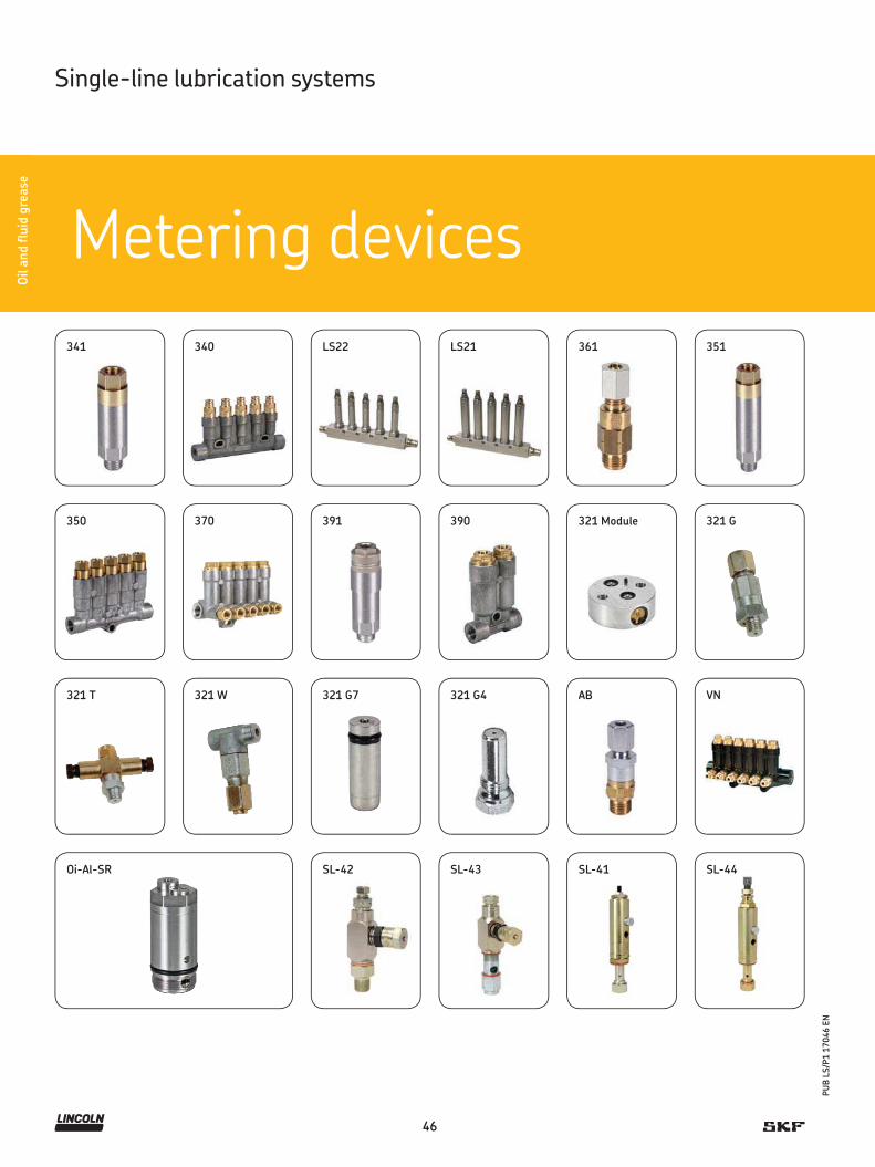
46
PU
B L
S/P
1 1
7046 E
N
Oil a
nd flu
id g
rease
LS21
Metering devices
Oil a
nd flu
id g
rease
Single-line lubrication systems
AB
LS22
SL-41SL-42 SL-43 SL-44
321 G
321 T 321 W 321 G4321 G7
321 Module
340341
350
351361
370 390391
VN
Oi-Al-SR

47
PU
B L
S/P
1 1
7046 E
N
Oil a
nd flu
id g
rease
Overview of oil and fluid grease metering devices
Product finder
Meteringdeviceseries
Category Lubricant Metering quantity Operating pressure Adjustment Function type
Pageoil fluid grease per stroke metering
000/00 quantity
cm 3 in3 bar psi
341 * 1 • – 0,01–0,16 0.0006–0.0097 6–80 87–1 160 – prelubrication 48340 1 • – 0,01–0,16 0.0006–0.0097 6–80 87–1 160 – prelubrication 50LS22 * 1 • – 0,01–0,16 0.0006–0.0097 12–20 174–290 – prelubrication 52LS21 * 1 • – 0,025–0,5 0.0015–0.0305 12–80 174–1 160 • prelubrication 53361 1, 2 • – 0,02–0,10 0.0010–0.0060 8–80 116–1 160 – dynamic pulse type 54351 * 1 • – 0,05–0,60 0.0030–0.0366 6–80 87–1 160 – prelubrication 56350 1 • – 0,05–0,60 0.0030–0.0366 6–80 87–1 160 – prelubrication 58370 1 • – 0,05–1,50 0.0030–0.0915 20–80 290–1 160 – relubrication 60391 1 • – 0,20–1,50 0.0122–0.0915 8–45 116–653 – prelubrication 62390 1 • – 0,20–1,50 0.0122–0.0915 8–80 116–1 160 – prelubrication 64
321 G, G4, T, W, Module
2 • • 0,01–0,10 0.0006–0.0060 12–45 174–653 – special assembly arrangement
66
361 2 • • 0,01–0,20 0.0006–0.0122 8–80 116–1 160 – dynamic pulse type 54321 G7 2 • • 0,01–0,30 0.0006–0.0183 12–45 174–653 – special assembly
arrangement66
AB * 2 • • 0,01–0,60 0.0006–0.0366 18–50 261–725 – prelubrication 68341 2 • • 0,03–0,10 0.0018–0.0061 6–80 87–1 160 – prelubrication 48340 2 • • 0,03–0,10 0.0018–0.0061 6–80 87–1 160 – prelubrication 50VN 2 • • 0,05–1,00 0.0030–0.0610 20–80 290–1 160 – relubrication 70351 2 • • 0,10–0,60 0.0061–0.0366 6–80 87–1 160 – prelubrication 56350 2 • • 0,10–0,30 0.0061–0.0183 6–80 87–1 160 – prelubrication 58
Oi-Al-SR 3 • • 0,02–0,10 0.0012–0.0061 30–100 435–1 450 – cartridge arrangement 72391 3 • • 0,10–0,30 0.0061–0.0183 8–45 116–653 – prelubrication 62390 3 • • 0,10–0,30 0.0061–0.0183 8–80 116–1 160 – prelubrication 64
SL-42 4 • • 0,016–0,049 0.001–0.0029 52–69 750–1 000 • prelubrication 74SL-43 4 • • 0,016–0,131 0.001–0.0080 52–69 750–1 000 • prelubrication 76SL-41 4 • • 0,13–1,31 0.0079–0.0799 52–69 750–1 000 • prelubrication 78SL-44 4 • • 0,13–1,31 0.0079–0.0799 52–69 750–1 000 • prelubrication 80
* Stainless steel or C5M available
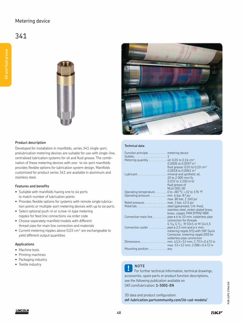
48
PU
B L
S/P
1 1
7046 E
N
Oil a
nd flu
id g
rease
Product description
Developed for installation in manifolds, series 341 single-port,
prelubrication metering devices are suitable for use with single-line,
centralized lubrication systems for oil and fluid grease. The combi-
nation of these metering devices with one- to six-port manifolds
provides flexible options for lubrication system design. Manifolds
customized for product series 341 are available in aluminum and
stainless steel.
Features and benefits
• Suitable with manifolds having one to six ports
to match number of lubrication points
• Provides flexible options for systems with remote single lubrica-
tion points or multiple-port metering devices with up to six ports
• Select optional push-in or screw-in type metering
nipples for feed line connections via order code
• Choose separately manifold models with different
thread sizes for main line connection and materials
• Current metering nipples above 0,03 cm³ are exchangeable to
yield different output quantities
Applications
• Machine tools
• Printing machines
• Packaging industry
• Textile industry
Technical data
Function principle . . . . . . . . . . . metering deviceOutlets. . . . . . . . . . . . . . . . . . . . 1Metering quantity . . . . . . . . . . . oil: 0,01 to 0,16 cm³
0.0006 to 0.0097 in³fluid grease: 0,03 to 0,10 cm³0.0018 to 0.0061 in³
Lubricant. . . . . . . . . . . . . . . . . . mineral and synthetic oil, 20 to 2 000 mm²/s, 0.031 to 3.100 in²/sfluid grease of NLGI 000, 00
Operating temperature . . . . . . . 0 to +80 °C; +32 to 176 °FOperating pressure . . . . . . . . . . min. 6 bar, 87 psi
max. 80 bar, 1 160 psiRelief pressure. . . . . . . . . . . . . . max. 3 bar, 43.5 psiMaterials . . . . . . . . . . . . . . . . . . steel (galvanized, Cr6-free),
stainless steel, nickel-plated brass, brass, copper, FKM (FPM)/ NBR
Connection main line . . . . . . . . . pipe ø 6 to 10 mm, solderless pipe connection for threads G 1/8; G 1/4; M 10×1 or M 14×1,5
Connection outlet . . . . . . . . . . . pipe ø 2,5 mm and ø 4 mm; metering nipple (VS) with SKF Quick Connector, metering nipple (00) for solderless pipe connection
Dimensions . . . . . . . . . . . . . . . . min. 43,5 × 12 mm; 1.713 × 0.472 inmax. 53 × 12 mm; 2.086 × 0.472 in
Mounting position . . . . . . . . . . . any
!NOTE
For further technical information, technical drawings,
accessories, spare parts or product function descriptions,
see the following publication available on
SKF.com/lubrication: 1-5001-EN
3D data and product configuration:
skf-lubrication.partcommunity.com/3d-cad-models/
Metering device
341

49
PU
B L
S/P
1 1
7046 E
N
Oil a
nd flu
id g
rease
Metering device
341
Design and metering quantity
Design code 2 4 8 5 9 1 7 6
Lubricant Oil Oil Oil Fluid grease Fluid grease Oil Fluid grease Oil
ø Outlet [mm] 2,5 4 4 4 4 4 4 4
Distributor body Steel Steel Steel Steel Steel Steel Steel Steel (1.4305)
Metering nipple Brass Brass Brass Brass (n.p.) Brass (n.p.) Brass Brass (n.p.) Steel (1.4305)
Elastomer NBR NBR FKM (FPM) NBR FKM (FPM) NBR NBR FKM (FPM)
Threaded seal FW2) FW2) FW2) FW2) Flat O-ring 3) O-ring 3) O-ring 3)
Connection outlet 00 VS 00 VS 00 VS 00 00 VS 00 VS 00 00
Met
erin
g qu
antity
cod
e 0,01 cm³ 1) 1 1 1 1 1 – – – 1 1 – – 10,02 cm³ 1) – – 6 – 6 – – – – 6 – – –0,03 cm³ 2 2 2 2 2 2 2 2 2 2 2 2 20,06 cm³ 3 3 3 3 3 3 3 3 3 3 3 3 30,10 cm³ 4 4 4 4 4 4 4 4 4 4 4 4 40,16 cm³ 5 5 5 5 5 – – – 5 5 – – 5
Order code 3 4 1 – – 0 0 0 0 – 0 0
Product series
Number of metering points (1)
1) Subsequent modification of the metering quantity is not technically possible. 2) FW=Flat washer must be ordered separately. Order number: DIN7603-A8×11.5-CU 3) O-ring is part of the shipment
Accessory
Manifold
Manifold VLOrder code V L –
Product series
Number of ports
01 = 1 screw-in point02 = 2 screw-in points03 = 3 screw-in points
04 = 4 screw-in points05 = 5 screw-in points06 = 6 screw-in points
(other numbers of ports available on request)
Design of metering device pipe thread
A = Normal profile, M8×1 with counterbore for O-ring D = Small profile, M8×1 without counterbore
Material
A = Aluminum E = Stainless steel (1.4305) (can only be selected for normal profile)
Design of main line connection
G1 = G 1/8 per DIN 3852-2, Form X, smallG2 = G 1/4 per DIN 3852-2, Form X, smallM 3 = M 10×1 with counterbore for solderless pipe connection per DIN 3862
M4 = M 14×1,5 with counterbore for solderless pipe connection per DIN 3862 (can only be selected for normal profile)
Product description
For 341 metering devices, VL-manifold s are
utilized for one to six screw-in points with
thread M8x1 mm for O-ring or flat (copper)
washer sealing. Normal-profile manifolds
are available in aluminum and stainless
steel, while narrow-profile manifolds are
offered in aluminum only.

50
PU
B L
S/P
1 1
7046 E
N
Oil a
nd flu
id g
rease
Product description
Offered in two-, three- and five-port models, series 340 metering
devices were developed for use with single-line, centralized lubrica-
tion systems for oil and fluid grease. These metering devices are de-
signed for installation directly on the machine/system requiring lu-
brication. Series 340 metering devices can be ordered with fittings
for the main line connection by selecting the appropriate order code.
Features and benefits
• Designed for installation directly
on the machine/system requiring lubrication
• Select optional push-in or screw-in type metering
nipples for feed line connections
• Choose optional push-in or screw-in type main line fittings
• Metering nipples above 0,03 cm³ are exchangeable to yield
different output quantities
Applications
• Machine tools
• Printing machines
• Packaging industry
• Textile industry
Technical data
Function principle . . . . . . . metering deviceOutlets. . . . . . . . . . . . . . . . 2, 3 or 5Metering quantity . . . . . . . oil: 0,01 to 0,16 cm 3
0.0006 to 0.0097 in³grease: 0,03 to 0,10 cm 3
0.0018 to 0.0061 in³Lubricant . . . . . . . . . . . . . mineral and synthetic oil,
20 to 2 000 mm²/s and fluid grease NLGI 000, 00
Operating temperature . . . 0 to +80 °C; +32 to 176 °FOperating pressure . . . . . . min. 6 bar, 87 psi; max. 80 bar, 1160 psiRelief pressure. . . . . . . . . . max. 3 bar, 43.5 psiMaterials . . . . . . . . . . . . . . zinc die-cast, brass (oil),
nickel-plated brass (fluid grease), copper, steel, FKM (FPM)/NBR
Connection main line . . . . . different fittings for pipe ø 6 to 10 mm or closure plugs for thread M 10×1
Connection outlet . . . . . . . pipe ø2,5 and ø 4 mm metering nipple (VS) with SKF quick connector, metering nipple (00) for solderless pipe connection
Dimensions . . . . . . . . . . . . min. 48 × 53 × 15 mm min. 1.889 × 2.086 × 0.590 in max. 99 × 58 × 15 mm max. 3.897 × 2.283 × 0.590 in
Mounting position . . . . . . . any
!NOTE
For further technical information, technical drawings,
accessories, spare parts or product function descriptions,
see the following publication available on
SKF.com/lubrication: 1-5001-EN
3D data and product configuration:
skf-lubrication.partcommunity.com/3d-cad-models/
Metering device
340
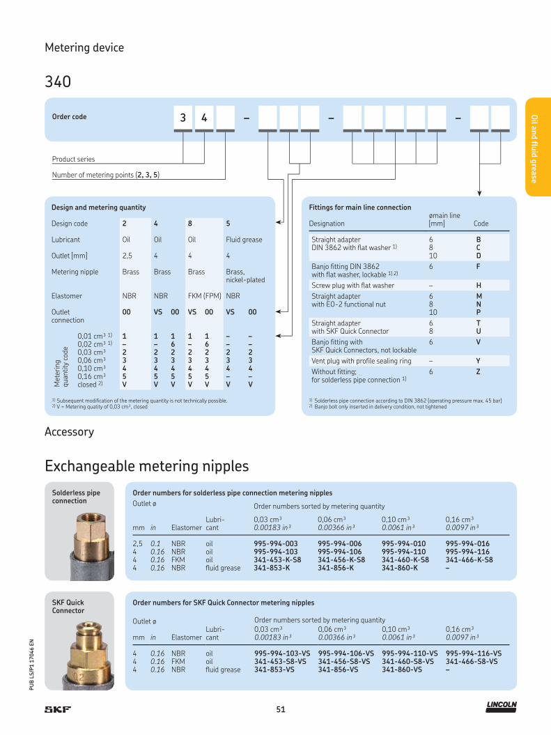
51
PU
B L
S/P
1 1
7046 E
N
Oil a
nd flu
id g
rease
Metering device
340
Design and metering quantity
Design code 2 4 8 5
Lubricant Oil Oil Oil Fluid grease
Outlet [mm] 2,5 4 4 4
Metering nipple Brass Brass Brass Brass, nickel-plated
Elastomer NBR NBR FKM (FPM) NBR
Outlet connection
00 VS 00 VS 00 VS 00
Met
erin
g qu
antity
cod
e
0,01 cm³ 1) 1 1 1 1 1 – –0,02 cm³ 1) – – 6 – 6 – –0,03 cm³ 2 2 2 2 2 2 20,06 cm³ 3 3 3 3 3 3 30,10 cm³ 4 4 4 4 4 4 40,16 cm³ 5 5 5 5 5 – –closed 2) V V V V V V V
Order code 3 4 – – –
Product series
Number of metering points (2, 3, 5)
Fittings for main line connection
Designationømain line [mm] Code
Straight adapter DIN 3862 with flat washer 1)
6 B8 C10 D
Banjo fitting DIN 3862with flat washer, lockable 1) 2)
6 F
Screw plug with flat washer – H
Straight adapter with EO-2 functional nut
6 M8 N10 P
Straight adapter with SKF Quick Connector
6 T8 U
Banjo fitting withSKF Quick Connectors, not lockable
6 V
Vent plug with profile sealing ring – Y
Without fitting; for solderless pipe connection 1)
6 Z
1) Subsequent modification of the metering quantity is not technically possible.2) V = Metering quatity of 0,03 cm³, closed
1) Solderless pipe connection according to DIN 3862 (operating pressure max. 45 bar)2) Banjo bolt only inserted in delivery condition, not tightened
SKF Quick Connector
Solderless pipe connection
Accessory
Exchangeable metering nipples
Order numbers for SKF Quick Connector metering nipples
Outlet ø
ElastomerLubri-cant
Order numbers sorted by metering quantity
mm in0,03 cm³0.00183 in³
0,06 cm³ 0.00366 in³
0,10 cm³ 0.0061 in³
0,16 cm³ 0.0097 in³
4 0.16 NBR oil 995-994-103-VS 995-994-106-VS 995-994-110-VS 995-994-116-VS4 0.16 FKM oil 341-453-S8-VS 341-456-S8-VS 341-460-S8-VS 341-466-S8-VS4 0.16 NBR fluid grease 341-853-VS 341-856-VS 341-860-VS –
Order numbers for solderless pipe connection metering nipples
Outlet ø
ElastomerLubri-cant
Order numbers sorted by metering quantity
mm in0,03 cm³0.00183 in³
0,06 cm³ 0.00366 in³
0,10 cm³ 0.0061 in³
0,16 cm³ 0.0097 in³
2,5 0.1 NBR oil 995-994-003 995-994-006 995-994-010 995-994-0164 0.16 NBR oil 995-994-103 995-994-106 995-994-110 995-994-1164 0.16 FKM oil 341-453-K-S8 341-456-K-S8 341-460-K-S8 341-466-K-S84 0.16 NBR fluid grease 341-853-K 341-856-K 341-860-K –

52
PU
B L
S/P
1 1
7046 E
N
Oil a
nd flu
id g
rease
Product description
Developed for installation in manifolds, LS22 are single-port meter-
ing devices for oil and special lubricants. When used in combination
with one- to five-port manifolds, these volumetric, prelubrication
metering devices provide flexible options for lubrication system de-
sign. Connections with or without (M8x1) a quick-release connector
are offered for feed lines and connections with a quick-release con-
nector are available for main line tubes.
Features and benefits
• For use with manifolds having one to five ports to
match number of lubrication points
• Compatible with ø 4 mm for feed lines and ø 8 for main lines
• Suitable for push-in or screw-in type fittings for dosers
and push-in type fittings for manifolds
• Robust, reliable
• Suitable for up to 200 lubrication points
Applications
• Conveyor chain surfaces and guides
• Food and beverage
• Packaging
Technical data
Function principle . . . . . . . metering deviceOutlets. . . . . . . . . . . . . . . . 1Metering quantity . . . . . . . 0,010 to 0,160 cm³
0.0006 to 0.0097 in³Lubricant . . . . . . . . . . . . . mineral and synthetic oil,
5 to 2 500 mm²/s; 0.007 to 3.875 in²/s or LDTS1 (dry film lubricant with synthetic oil and PTFE additions)
Operating temperature . . . 0 to +50 °C; +32 to 122 °FOperating pressure . . . . . . min. 12 bar; 174 psi
max. 20 bar; 290 psiRelief pressure. . . . . . . . . . max. 3 bar; 43.5 psiMaterials . . . . . . . . . . . . . . stainless steel 303, FKM (FPM),
high phosphorus FDA chem. nickel-plated brass
Connection main line . . . . . push-in connectors for pipe ø 8 mm and thread G 1/4
Connection outlet . . . . . . . with or without push-in connectors for pipe ø 4 mm and thread M 10x1
Dimensions . . . . . . . . . . . . min. 89 × 68,5 × 20 mmmin. 3.5 × 2.67 × 0.8 inmax. 179 × 84 × 20 mmmax. 7.0 × 3.3 × 0.8 in
Mounting position . . . . . . . any
!NOTE
For further technical information, technical drawings,
accessories, spare parts or product function descriptions,
see the following publication available on
SKF.com/lubrication: 15848 EN
Metering device
LS22
Order numbers
Order number. Outlet(s)
LS2210 1LS2220 2LS2230 3LS2240 4LS2250 5

53
PU
B L
S/P
1 1
7046 E
N
Oil a
nd flu
id g
rease
Product description
Developed for installation in manifolds, LS21 are single-port meter-
ing devices for oil and special lubricants. When used in combination
with one- to five-port manifolds, these volumetric, prelubrication
metering devices provide flexible options for lubrication system de-
sign. Connections with or without (M8x1) a quick-release connector
are offered for feed lines, and connections with a quick-release
connector are available for main line tubes.
Features and benefits
• For use with manifolds having one to five ports
to match number of lubrication points
• Compatible with ø 4 mm for feedlines and ø 8 for main lines
• Suitable for push-in type fittings for dosers and manifolds
• Robust, reliable
• Suitable for up to 200 lubrication points
Applications
• Conveyor chain surfaces and guides
• Food and beverage
• Packaging
Technical data
Function principle . . . . . . . adjustable metering deviceOutlets. . . . . . . . . . . . . . . . 1Metering quantity . . . . . . . adjustable 0,025 to 0,5 cm 3
0.0015 to 0.0305 in³Lubricant . . . . . . . . . . . . . mineral and synthetic oil,
5 to 2 500 mm²/s; 0.007 to 3.875 in²/s or LDTS1 (dry film lubricant with synthetic oil and PTFE additions)
Operating temperature . . . 0 to + 50 °C; +32 to 122 °FOperating pressure . . . . . . min. 12 bar; 174 psi
max. 20 bar; 290 psiRelief pressure. . . . . . . . . . max. 3 bar; 43.5 psiMaterials . . . . . . . . . . . . . . stainless steel 303, FKM (FPM), high
phosphorus FDA chem. nickel-plated brassConnection main line . . . . . push-in connectors for pipe
ø 8 mm and thread G 1/4Connection outlet . . . . . . . with or without push-in connectors
for pipe ø 4 mm and thread M 10×1Working frequency . . . . . . ≤ 1 stroke/2 sDimensions . . . . . . . . . . . . min. 89 × 92 × 20 mm
min. 3.5 × 3.622× 0.8 inmax. 179 × 110 × 20 mmmax. 7.0 × 4.330 × 0.8 in
Mounting position . . . . . . . any
!NOTE
For further technical information, technical drawings,
accessories, spare parts or product function descriptions,
see the following publication available on
SKF.com/lubrication: 15848 EN
Metering device
LS21
Order numbers
Order number. Outlet(s)
LS2110 1LS2120 2LS2130 3LS2140 4LS2150 5
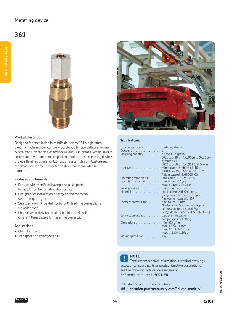
54
PU
B L
S/P
1 1
7046 E
N
Oil a
nd flu
id g
rease
Product description
Designed for installation in manifolds, series 361 single-port,
dynamic metering devices were developed for use with single-line,
centralized lubrication systems for oil and fluid grease. When used in
combination with one- to six-port manifolds, these metering devices
provide flexible options for lubrication system design. Customized
manifolds for series 361 metering devices are available in
aluminum.
Features and benefits
• For use with manifolds having one to six ports
to match number of lubrication points
• Designed for installation directly on the machine/
system requiring lubrication
• Select screw-in type distributor with feed line connections
via order code
• Choose separately optional manifold models with
different thread sizes for main line connection
Applications
• Chain lubrication
• Transport and conveyor belts
Technical data
Function principle . . . . . . . . . . . metering deviceOutlets. . . . . . . . . . . . . . . . . . . . 1Metering quantity . . . . . . . . . . . oil and fluid grease:
0,01 to 0,20 cm³; 0.0006 to 0.012 in³synthetic oil:0,02 to 0,10 cm³; 0.001 to 0.006 in³
Lubricant . . . . . . . . . . . . . . . . . mineral and synthetic oil: 10 to1 000 mm²/s, 0.015 to 1.55 in²/sfluid grease of NLGI 000, 00
Operating temperature . . . . . . . 0 to +80 °C; +32 to 176 °FOperating pressure . . . . . . . . . . min. 8 bar, 116 psi
max. 80 bar, 1 160 psiRelief pressure. . . . . . . . . . . . . . max. 3 bar; 43.5 psiMaterials . . . . . . . . . . . . . . . . . . steel (galvanized, Cr6-free),
(oil, grease), brass (oil), copper, flat washer (copper), NBR
Connection main line . . . . . . . . . pipe ø 6 to 12 mm, 0.236 to 0.472 in; solderless pipeconnection for threads G 1/8; G 1/4; M 10×1 or M 14×1,5 (DIN 3862)
Connection outlet . . . . . . . . . . . pipe ø 4 mm straight compression nut fitting
Dimensions . . . . . . . . . . . . . . . . min. 42 × 14 mmmax. 46,5 × 14 mmmin. 1.653 × 0.551 inmax. 1.830 × 0.551 in
Mounting position . . . . . . . . . . . any
!NOTE
For further technical information, technical drawings,
accessories, spare parts or product function descriptions,
see the following publication available on
SKF.com/lubrication: 1-5001-EN
3D data and product configuration:
skf-lubrication.partcommunity.com/3d-cad-models/
Metering device
361

55
PU
B L
S/P
1 1
7046 E
N
Oil a
nd flu
id g
rease
Metering device
361
Design and metering quantity
Design code 1 2
Lubricant oil, fluid grease Oil
ø Outlet [mm] 4 4
Body steel, galvanized brass
Metering nipple material steel, galvanized brass
Elastomer NBR NBR
Connection outlet 00 00
Met
erin
g qu
antity
cod
e [c
m³]
0,01 1 –0,02 2 20,03 3 30,05 4 40,10 5 50,20 6 –
Order code 3 6 1 – 0 0 – 0 0 0 0 – 0 0
Product series
Number of metering points (1)
* Flat washer must be ordered separately. Order number: 504-019
Accessory
Manifold
Manifold VLOrder code V L –
Product series
Number of ports
01 = 1 screw-in point02 = 2 screw-in points03 = 3 screw-in points
04 = 4 screw-in points05 = 5 screw-in points06 = 6 screw-in points
(other numbers of ports available on request)
Design of metering device pipe thread
B = Normal profile, M 10×1 with counterbore for flat washer or O-ring E = Narrow profile, M 10×1 with counterbore for flat washer
Material
A = Aluminum E = Stainless steel (1.4305) (can only be selected for normal profile)
Design of main line connection
G1 = G 1/8 per DIN 3852-2, Form X, smallG2 = G 1/4 per DIN 3852-2, Form X, smallM 3 = M 10×1 with counterbore for solderless pipe connection per DIN 3862
M4 = M 14×1,5 with counterbore for solderless pipe connection per DIN 3862 (can only be selected for normal profile)
Product description
For 361 metering devices, VL-manifolds
are utilized for one to six screw-in points
with thread M 10×1 mm for flat washer
sealing. Various main line connections
can be selected via order code.

56
PU
B L
S/P
1 1
7046 E
N
Oil a
nd flu
id g
rease
Product description
Designed for installation in manifolds, series 351 single-port,
prelubrication metering devices were developed for use with single-
line, centralized lubrication systems for oil and fluid grease. When
used in combination with one- to six-port manifolds, these metering
devices provide flexible options for lubrication system design. Cus-
tomized manifolds for series 351 metering devices are available in
aluminum and stainless steel.
Features and benefits
• For use with manifolds having one to six ports
to match number of lubrication points
• Provides flexible options for systems with remote single lubrica-
tion points or multiple-port metering devices with up to six ports
• Select optional push-in or screw-in type nipples for feed line
connections
• Choose separately manifold models with different
thread sizes for main line connection and materials
• Current metering nipples are exchangeable to yield
different output quantities
Applications
• Machine tools
• Printing machines
• Packaging industry
• Textile industry
Technical data
Function principle . . . . . . . . . . . metering deviceOutlets. . . . . . . . . . . . . . . . . . . . 1Metering quantity . . . . . . . . . . . oil: 0,05 to 0,60 cm³
0.0030 to 0.0366 in³ fluid grease: 0,10 to 0,60 cm³0.0061 to 0.0366 in³
Lubricant . . . . . . . . . . . . . . . . . mineral and synthetic oil, 20 to 2 000 mm²/s and fluid grease NLGI 000, 00
Operating temperature . . . . . . . 0 to +80 °C; +32 to 176 °FOperating pressure . . . . . . . . . . min. 6 bar, 87 psi;
max. 80 bar, 1 160 psiRelief pressure. . . . . . . . . . . . . . max. 3 bar, 43.5 psiMaterials . . . . . . . . . . . . . . . . . . aluminum, stainless steel, brass (oil),
nickel-plated brass (grease), flat washer (copper, stainless steel), FKM (FPM)/NBR
Connection main line . . . . . . . . . pipe ø 6 to 12 mm solderless pipe connection for threads G 1/8; G 1/4; M 10 × 1 or M 14 × 1,5 (DIN 3862)
Connection outlet . . . . . . . . . . . pipe ø 4 mm metering nipple (VS) with SKF Quick Connector - metering nipple (00) for solderless pipe connection
Dimensions . . . . . . . . . . . . . . . . min. 43,5 × 12 mm; 1.713 × 0.472 in max. 53 × 12 mm; 2.086 × 0.472 in
Mounting position . . . . . . . . . . . any
!NOTE
For further technical information, technical drawings,
accessories, spare parts or product function descriptions,
see the following publication available on
SKF.com/lubrication: 1-5001-EN
3D data and product configuration:
skf-lubrication.partcommunity.com/3d-cad-models/
Metering device
351

57
PU
B L
S/P
1 1
7046 E
N
Oil a
nd flu
id g
rease
Metering device
351
Design and metering quantity
Design code 0 8 4 1 7 2 3 6
Lubricant Oil Oil Oil Fluid grease Fluid grease Oil Fluid grease Oil
ø Outlet [mm] 4 4 4 4 4 4 4 4
Body Aluminum Aluminum Steel (1.4305) Aluminum Aluminum Aluminum Aluminum Steel (1.4305)
Metering nipple Brass Brass Steel (1.4305) Brass (n.p.) Brass (n.p.) Brass Brass (n.p.) Steel (1.4305)
Elastomer NBR FKM (FPM) FKM (FPM) NBR FKM (FPM) NBR NBR FKM (FPM)
Threaded seal FW 1) FW 1) Steel (1.4305) 2) FW 1) FW 1) O-ring 3) O-ring 3) O-ring 3)
Connection outlet VS 00 VS 00 00 VS 00 VS 00 VS 00 VS 00 00
Met
erin
g qu
antity
cod
e 0,05 cm³ 3 3 3 3 – – – – – – – – – –0,10 cm³ 4 4 4 4 4 4 4 4 4 4 4 4 4 40,20 cm³ 5 5 5 5 5 5 5 5 5 5 5 5 5 50,30 cm³ – – – – – 6 6 6 6 – – 6 6 –0,40 cm³ 6 6 6 6 6 – – – – 6 6 – – 60,60 cm³ 7 7 7 7 7 – 7 – – 7 7 – – 7
Order code 3 5 1 – – 0 0 0 0 – 0 0
Product series
Number of metering points (1)
1) Flat washer must be ordered separately. Order number: 504-0192) Stainless steel ring must be ordered separately. Order number: 99-1031-7603 3) O-ring is part of the shipment
Accessory
Manifold
Manifold VLOrder code V L –
Product series
Number of ports
01 = 1 screw-in point02 = 2 screw-in points03 = 3 screw-in points
04 = 4 screw-in points05 = 5 screw-in points06 = 6 screw-in points
(other numbers of ports available on request)
Design of metering device pipe thread
B = Normal profile, M 10×1 with counterbore for flat washer or O-ring E = Narrow profile, M 10×1 with counterbore for flat washer
Material
A = Aluminum E = Stainless steel (1.4305) (can only be selected for normal profile)
Design of main line connection
G1 = G 1/8 per DIN 3852-2, Form X, smallG2 = G 1/4 per DIN 3852-2, Form X, smallM 3 = M 10×1 with counterbore for solderless pipe connection per DIN 3862
M4 = M 14x1,5 with counterbore for solderless pipe connection per DIN 3862 (can only be selected for normal profile)
Product description
For 351 metering devices, VL-manifolds are
utilized for one to six screw-in points with
thread M 10×1 mm for O-ring or flat (cop-
per) washer sealing. Various main line con-
nections can be selected via order code.

58
PU
B L
S/P
1 1
7046 E
N
Oil a
nd flu
id g
rease
Product description
Designed for installation directly on the machine/system requiring
lubrication, series 350 single-line, prelubrication metering devices
are available in two-, three- and five-port models. These metering
devices were developed for use with single-line, centralized lubrica-
tion systems for oil and fluid grease. Series 350 metering devices
can be ordered with fittings for the main line connection by selecting
the appropriate order code.
Features and benefits
• For use with distributor bodies having two, three and
five ports to match number of lubrication points
• Designed for installation directly on
the machine/system requiring lubrication
• Select push-in or screw-in type metering nipples for feed line
connection with metering device bodies
• Choose push-in or screw-in type main line fittings
with metering device bodies
• Current metering nipples above 0,03 cm³ are exchangeable
to yield different output quantities
Applications
• Machine tools
• Printing machines
• Packaging industry
• Textile industry
• Agriculture !NOTE
For further technical information, technical drawings,
accessories, spare parts or product function descriptions,
see the following publication available on
SKF.com/lubrication: 1-5001-EN
3D data and product configuration:
skf-lubrication.partcommunity.com/3d-cad-models/
Technical data
Function principle . . . . . . . . . . . metering deviceOutlets. . . . . . . . . . . . . . . . . . . . 2, 3 or 5Metering quantity . . . . . . . . . . . oil: 0,05 to 0,60 cm³
0.003 to 0.037 in³grease: 0,10 to 0,30 cm³ 0.0061 to 0.0183 in³
Lubricant . . . . . . . . . . . . . . . . . mineral and synthetic oil, 20 to 2 000 mm²/s and fluid grease NLGI 000, 00
Operating temperature . . . . . . . 0 to +80 °C; +32 to 176 °FOperating pressure . . . . . . . . . . min. 6 bar, 87 psi;
max. 80 bar, 1 160 psiRelief pressure. . . . . . . . . . . . . . max. 3 bar, 43.5 psiMaterials . . . . . . . . . . . . . . . . . . zinc die-cast, brass (oil), nickel-plated
brass (fluid grease), copper, steel,FKM (FPM)/NBR
Connection main line . . . . . . . . . different fittings for pipe ø 6 to 10 mm; 0.236 to 0.393 in or closure plugs for thread M 12×1
Connection outlet . . . . . . . . . . . pipe ø 4 mm metering nipple (VS) with SKF Quick Connector - metering nipple (00) for solderless pipe connection
Dimensions . . . . . . . . . . . . . . . . min. 46 × 83 × 18 mmmin. 1.811 × 3.267 × 0.708 inmax. 97 × 86 × 18 mmmax. 3.818 × 3.385 × 0.708 in
Mounting position . . . . . . . . . . . any
Metering device
350

59
PU
B L
S/P
1 1
7046 E
N
Oil a
nd flu
id g
rease
Oil a
nd flu
id g
rease
59
Metering device
350
Order code 3 5 – – –
Product series
Number of metering points (2, 3, 5)
Fittings for main line connection
DesignationMain line [mm] Code
Straight adapter DIN 3862 with flat washer 1)
6 B8 C10 D
Banjo fitting DIN 3862with flat washer, lockable 1) 2)
6 E8 F
Screw plug with flat washer – H
Straight adapter with EO-2 functional nut
6 M8 N10 P12 R
Straight adapter with SKF Quick Connector
6 S8 T
Banjo fitting withSKF Quick Connectors
6 W8 X
Without fitting (M 12x1 thread) – Z
Design and metering quantity
Design code 0 8 1 7
Lubricant Oil Oil Fluid grease Fluid grease
ø Outlet [mm] 4 4 4 4
Metering nipple Brass Brass Brass (n.p.) Brass (n.p.)
Elastomer NBR FKM (FPM) NBR FKM (FPM)
Outlet connection
VS 00 VS 00 VS 00 VS 00
Met
erin
g qu
antity
co
de
0,05 cm³ 3 3 3 3 – – – –0,10 cm³ 4 4 4 4 4 4 4 40,20 cm³ 5 5 5 5 5 5 5 50,30 cm³ – – – – 6 6 6 60,40 cm³ 6 6 6 6 – – – –0,60 cm³ 7 7 7 7 – 7 – –closed * V V V V V V V V
1) Solderless pipe connection according to DIN 3862 (operating pressure max. 45 bar)2) Banjo bolt only inserted in delivery condition, not tightened* V = Metering quatity of 0,20 cm³, closed
Accessory
Exchangeable metering nipples
Order numbers for metering nipples for oil (replaceable)
Outlet øMaterial Elastomer
Metering nipple
Metering quantity
mm in0,05 cm³0.003 in³
0,10 cm³0.006 in³
0,20 cm³0.012 in³
0,40 cm³0.024 in³
0,60 cm³0.036 in³
4 0.16 NBR 00 352-005-K 352-010-K 352-020-K 352-040-K 352-060-K4 0.16 NBR VS 352-005-VS 352-010-VS 352-020-VS 352-040-VS 352-060-VS4 0.16 FKM (FPM) 00 352-005-K-S8 352-010-K-S8 352-020-K-S8 352-040-K-S8 352-060-K-S84 0.16 FKM (FPM) VS 352-005-S8-VS 352-010-S8-VS 352-020-S8-VS 352-040-S8-VS 352-060-S8-VS
Order numbers for metering nipples for fluid grease (replaceable)
Outlet øMaterial Elastomer
Metering nipple
Metering quantity
mm in0,10 cm³0.006 in³
0,20 cm³0.012 in³
0,30 cm³0.018 in³
0,60 cm³0.036 in³
4 0.16 NBR 00 995-993-610 995-993-620 995-993-630 995-993-6604 0.16 NBR VS 995-993-610-VS 995-993-620-VS 995-993-630-VS –4 0.16 FKM (FPM) 00 352-010-K-S82 352-020-K-S82 352-030-K-S82 –4 0.16 FKM (FPM) VS 352-010-S82-VS 352-020-S82-VS 352-030-S82-VS –

60
PU
B L
S/P
1 1
7046 E
N
Oil a
nd flu
id g
rease
Product description
Series 370 relubrication metering devices were developed for use
with single-line, centralized lubrication systems for oil. Designed for
installation directly on the machine/system requiring lubrication,
these metering devices are available in two-, three- and five-port
models. Series 370 metering devices can be ordered with fittings for
the main line connection by selecting the appropriate order code.
Features and benefits
• For use with distributor bodies having two, three and
five ports to match number of lubrication points
• Designed for installation directly on the machine/
system requiring lubrication
• Choose optional metering nipples and push-in or screw-in
type fittings for feed line connections
• Select SKF Quick Connector or screw-in type main line fittings
• Current metering nipples are easily exchangeable
to yield different output quantities
Applications
• Machine tools
• Printing machines
• Packaging industry
• Textile industry
Technical data
Function principle . . . . . . . . . . . metering deviceOutlets. . . . . . . . . . . . . . . . . . . . 2, 3 or 5Metering quantity . . . . . . . . . . . 0,05 to 1,50 cm³
0.003 to 0.091 in³Lubricant . . . . . . . . . . . . . . . . . mineral and synthetic oil
20 to 2 000 mm²/s 0.031 to 3.100 in²/s
Operating temperature . . . . . . . –20 to +80 °C; –4 to 176 °FOperating pressure . . . . . . . . . . min. 20 bar, 290 psi
max. 80 bar, 1 160 psiRelief pressure. . . . . . . . . . . . . . ≤1 bar, 14.5 psiMaterials . . . . . . . . . . . . . . . . . . zinc die-cast, brass, copper, steel, NBR Connection main line . . . . . . . . . different fittings for pipe ø 6 to 12 mm;
0.236 to 0.472 in or closure plugs for thread M 12×1
Connection outlet . . . . . . . . . . . pipe ø 4 mm; 0.16 in - metering nipple (VS) with SKF Quick Connector - metering nipple (00) for solderless pipe connection (DIN 3862)
Dimensions . . . . . . . . . . . . . . . . min. 37 × 75 × 50,5 mm min. 1.456 × 2.952 × 1.988 in max. 88 × 75 × 56,5 mm max. 3.464 × 2.952 × 2.224 in
Mounting position . . . . . . . . . . . any
!NOTE
For further technical information, technical drawings,
accessories, spare parts or product function descriptions,
see the following publication available on
SKF.com/lubrication: 1-5001-EN
3D data and product configuration:
skf-lubrication.partcommunity.com/3d-cad-models/
Metering device
370
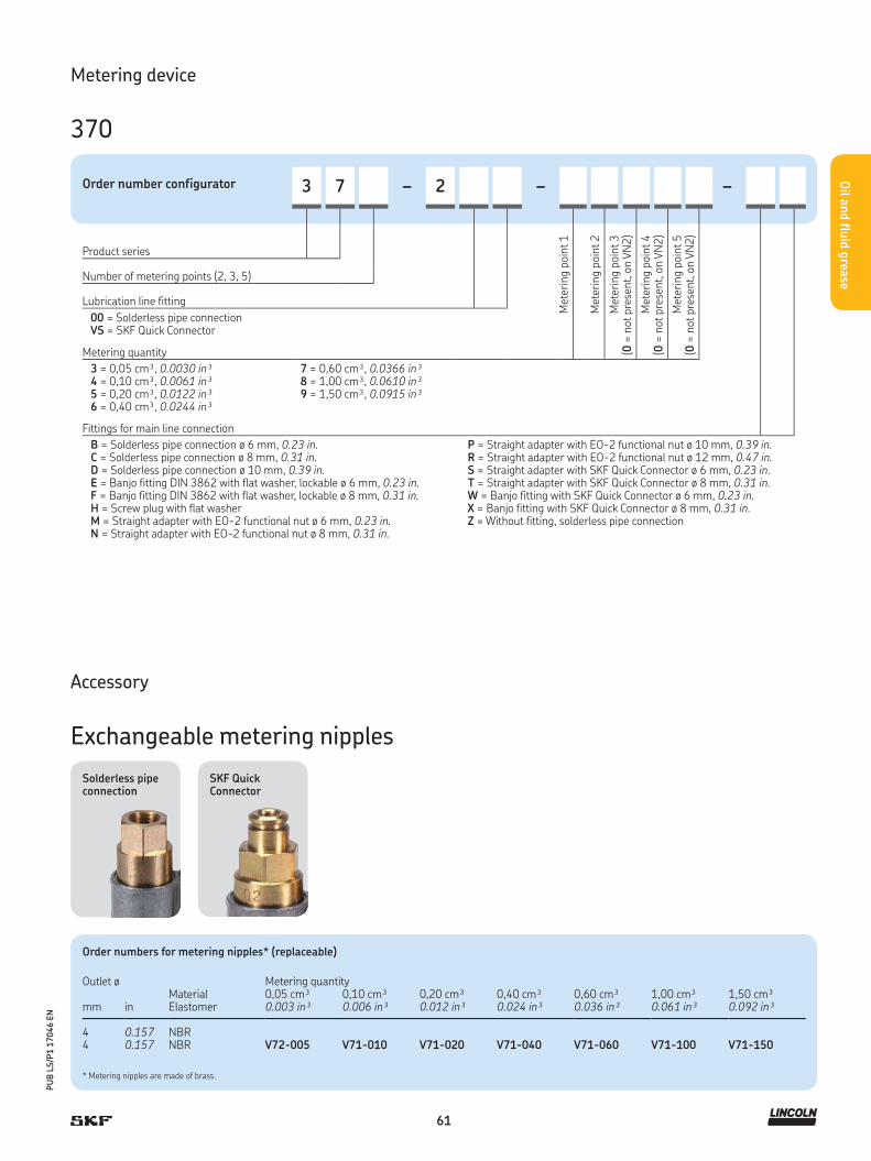
61
PU
B L
S/P
1 1
7046 E
N
Oil a
nd flu
id g
rease
Order number configurator 3 7 – 2 – –
Met
erin
g poi
nt 1
Met
erin
g poi
nt 2
Met
erin
g poi
nt 3
(0 =
not
pre
sent, o
n V
N2)
Met
erin
g poi
nt 4
(0 =
not
pre
sent, o
n V
N2)
Met
erin
g poi
nt 5
(0 =
not
pre
sent, o
n V
N2)
Product series
Number of metering points (2, 3, 5)
Lubrication line fitting
00 = Solderless pipe connectionVS = SKF Quick Connector
Metering quantity
3 = 0,05 cm³, 0.0030 in³4 = 0,10 cm³, 0.0061 in³5 = 0,20 cm³, 0.0122 in³6 = 0,40 cm³, 0.0244 in³
7 = 0,60 cm³, 0.0366 in³8 = 1,00 cm³, 0.0610 in³9 = 1,50 cm³, 0.0915 in³
Fittings for main line connection
B = Solderless pipe connection ø 6 mm, 0.23 in.C = Solderless pipe connection ø 8 mm, 0.31 in.D = Solderless pipe connection ø 10 mm, 0.39 in.E = Banjo fitting DIN 3862 with flat washer, lockable ø 6 mm, 0.23 in. F = Banjo fitting DIN 3862 with flat washer, lockable ø 8 mm, 0.31 in.H = Screw plug with flat washerM = Straight adapter with EO-2 functional nut ø 6 mm, 0.23 in.N = Straight adapter with EO-2 functional nut ø 8 mm, 0.31 in.
P = Straight adapter with EO-2 functional nut ø 10 mm, 0.39 in.R = Straight adapter with EO-2 functional nut ø 12 mm, 0.47 in.S = Straight adapter with SKF Quick Connector ø 6 mm, 0.23 in.T = Straight adapter with SKF Quick Connector ø 8 mm, 0.31 in.W = Banjo fitting with SKF Quick Connector ø 6 mm, 0.23 in. X = Banjo fitting with SKF Quick Connector ø 8 mm, 0.31 in.Z = Without fitting, solderless pipe connection
Metering device
370
Order numbers for metering nipples* (replaceable)
Outlet øMaterial Elastomer
Metering quantity
mm in0,05 cm³0.003 in³
0,10 cm³0.006 in³
0,20 cm³0.012 in³
0,40 cm³0.024 in³
0,60 cm³0.036 in³
1,00 cm³0.061 in³
1,50 cm³0.092 in³
4 0.157 NBR4 0.157 NBR V72-005 V71-010 V71-020 V71-040 V71-060 V71-100 V71-150
* Metering nipples are made of brass.
SKF Quick Connector
Solderless pipe connection
Accessory
Exchangeable metering nipples

62
PU
B L
S/P
1 1
7046 E
N
Oil a
nd flu
id g
rease
Product description
Series 391 single-port prelubrication metering devices were
developed for use with single-line, centralized lubrication systems
for oil and fluid grease. Designed for installation in manifolds, these
metering devices provide flexible system design when combined
with one- to six-port manifolds. Customized manifolds for series
391 are available in aluminum.
Features and benefits
• For use with manifolds having one to six ports
to match number of lubrication points
• Provides flexible options for systems with remote single
lubrication points or multiple-port metering devices
with up to six ports
• Select screw-in type metering nipples with
feed line connections via order code
• Choose separately manifold models with different
thread sizes for main line connection
• Current metering nipples are exchangeable to yield
different output quantities
Applications
• Machine tools
• Printing machines
• Packaging industry
• Textile industry
Technical data
Function principle . . . . . . . . . . . metering deviceOutlets. . . . . . . . . . . . . . . . . . . . 1Metering quantity . . . . . . . . . . . oil: 0,2 to 1,5 cm³; 0.01 to 0.09 in³
fluid grease: 0,1 to 0,3 cm³0.006 to 0.02 in³
Lubricant . . . . . . . . . . . . . . . . . mineral and synthetic oil, 20 to 2 000 mm²/s, fluid grease NLGI 000, 00
Operating temperature . . . . . . . 0 to +80 °C; +32 to 176 °FOperating pressure . . . . . . . . . . min. 8 bar, 116 psi
max. 45 bar, 653 psiRelief pressure. . . . . . . . . . . . . . max. 7 bar; 101.5 psiMaterials . . . . . . . . . . . . . . . . . . aluminum, brass (oil), nickel-plated
brass (fluid grease), copper, FKM (FPM)/NBR
Connection main line . . . . . . . . . pipe ø 6 to 12 mm 0.236 to 0.472 insolderless pipe connection for threads G 1/8; G 1/4; M 10×1 or M 14×1,5 (DIN 3862)
Connection outlet . . . . . . . . . . . pipe ø 4 mm; 0.16 in - metering nipple (00) for solderless pipe connection
Dimensions . . . . . . . . . . . . . . . . min. 67,5 × 22 mm min. 2.657 × 0.866 inmax. 78,5 × 22 mmmax. 3.091 × 0.866 in
Mounting position . . . . . . . . . . . any
!NOTE
For further technical information, technical drawings,
accessories, spare parts or product function descriptions,
see the following publication available on
SKF.com/lubrication: 1-5001-EN
3D data and product configuration:
skf-lubrication.partcommunity.com/3d-cad-models/
Metering device
391

63
PU
B L
S/P
1 1
7046 E
N
Oil a
nd flu
id g
rease
Metering device
391
Design and metering quantity
Design code 0 8 1
Lubricant Oil Oil Fluid grease
ø Outlet [mm] 4 4 4
Body aluminum aluminum aluminum
Metering nipple brass brass brass, nickel-plated
Elastomer NBR FKM (FPM) NBR
Threaded seal Flat washer* Flat washer* Flat washer*
Connection outlet 00 00 00
Met
erin
g qu
antity
cod
e
0,10 cm³ – – 40,20 cm³ 5 5 50,30 cm³ – – 60,40 cm³ 6 6 –0,60 cm³ 7 7 –1,00 cm³ 8 8 –1,50 cm³ 9 9
Order code 3 9 1 – 0 0 – 0 0 0 0 – 0 0
Product series
Number of metering points (1)
* Flat washer must be ordered separately. Order number: DIN7603-A14x18-CU
Accessory
Manifold
Manifold VLOrder code V L – C A
Product series
Number of ports
01 = 1 screw-in point02 = 2 screw-in points03 = 3 screw-in points
04 = 4 screw-in points05 = 5 screw-in points06 = 6 screw-in points
(other numbers of ports available on request)
Design of metering device pipe thread
C = Normal profile, M 14×1,5 with counterbore for flat washer
Material
A = Aluminum
Design of main line connection
G1 = G 1/8 per DIN 3852-2, Form X, schmalG2 = G 1/4 per DIN 3852-2, Form X, schmalM 3 = M 10×1 with counterbore for solderless pipe connection per DIN 3862
M4 = M 14x1,5 with counterbore for solderless pipe connection per DIN 3862 (can only be selected for normal profile)
Product description
For 391 metering devices, VL-manifolds are
utilized for one to six screw-in points with
thread M 14×1,5 mm for flat (copper) wash-
er sealing. Various main line connections
can be selected via order code.

64
PU
B L
S/P
1 1
7046 E
N
Oil a
nd flu
id g
rease
Product description
Series 390 prelubrication metering devices were developed for
use with single-line, centralized lubrication systems for oil and fluid
grease. Designed for installation directly on the machine/system
requiring lubrication, these metering devices can be ordered with
fittings for the main line connection by selecting the appropriate
order code.
Features and benefits
• For use with distributor bodies having two or three ports
to match number of lubrication points
• Designed for installation directly on the machine/
system requiring lubrication
• Select screw-in type metering nipples
for feed line connections
• Choose push-in or screw-in type main line fittings
• Current metering nipples are exchangeable
to yield different output quantities
Applications
• Machine tools
• Printing machines
• Packaging industry
• Textile industry
Technical data
Function principle . . . . . . . . . . . metering deviceOutlets. . . . . . . . . . . . . . . . . . . . 2 or 3Metering quantity . . . . . . . . . . . oil: 0,2 to 1,5 cm³
0.01 to 0.915 in³fluid grease: 0,1 to 0,3 cm³0.006 to 0.0183 in³
Lubricant . . . . . . . . . . . . . . . . . mineral and synthetic oil20 to 2 000 mm²/s0.031 to 3.100 in²/sfluid grease of NLGI 000, 00
Operating temperature . . . . . . . 0 to +80 °C; +32 to 176 °FOperating pressure . . . . . . . . . . min. 8 bar, 116 psi
max. 45 bar, 653 psiRelief pressure. . . . . . . . . . . . . . max. 7 bar, 101.5 psiMaterials . . . . . . . . . . . . . . . . . . zinc die-cast, brass (oil), nickel-plated
brass (fluid grease), copper, steel, FKM (FPM)/NBR
Connection main line . . . . . . . . . different fittings for pipe ø 6 to 12 mm; 0.236 to 0.472 inor closure plugs for thread M 12×1
Connection outlet . . . . . . . . . . . pipe ø 4 mm; 0.16 in - metering nipple (00) for solderless pipe connection (DIN 3862)
Dimensions . . . . . . . . . . . . . . . . min. 50 × 89 × 23 mm min. 1.968 × 3.503 × 0.905 in max. 71 × 89 × 23 mm max. 5.393 × 3.503 × 0.905 in
Mounting position . . . . . . . . . . . any
!NOTE
For further technical information, technical drawings,
accessories, spare parts or product function descriptions,
see the following publication available on
SKF.com/lubrication: 1-5001-EN
3D data and product configuration:
skf-lubrication.partcommunity.com/3d-cad-models/
Metering device
390

65
PU
B L
S/P
1 1
7046 E
N
Oil a
nd flu
id g
rease
Metering device
390
Design and metering quantity
Design code 0 8 1
Lubricant Oil Oil Fluid grease
ø Outlet [mm] 4 4 4
Body aluminum aluminum aluminum
Metering nipple brass brass brass (n.p.)
Elastomer NBR FKM (FPM) NBR
Connection outlet 00 00 00
Met
erin
g q
uan
tity
co
de
0,10 cm³ – – 40,20 cm³ 5 5 50,30 cm³ – – 60,40 cm³ 6 6 –0,60 cm³ 7 7 –1,00 cm³ 8 8 –1,50 cm³ 9 9 –closed * V V V
Order code 3 9 – 0 0 – 0 0 –
Product series
Number of metering points (2, 3)
Fittings for main line connection
Designationømain line [mm] Code
Straight adapter DIN 3862 with flat washer
6 B8 C10 D
Banjo fitting DIN 3862with flat washer, lockable 1)
6 E8 F
Screw plug with flat washer – H
Straight adapter with EO-2 functional nut
6 M8 N10 P12 R
Straight adapter with SKF Quick Connector
6 S8 T
Banjo fitting with SKF Quick Connector, not lockable
6 W8 X
Without fitting (M 12x1 thread) – Z
1) Banjo bolt only inserted in delivery condition, not tightened* V = Metering quatity of 0,20 cm³, closed
Accessory
Exchangeable metering nipples
Order numbers for metering nipples for oil (replaceable)
Outlet øMaterial Elastomer metering nipple
Metering quantity
mm in0,2 cm³0.012 in³
0,4 cm³0.024 in³
0,6 cm³0.036 in³
1,0 cm³0.061 in³
1,5 cm³0.092 in³
4 0.16 NBR brass 391-020-K 391-040-K 391-060-K 391-100-K 391-150-K4 0.16 FKM (FPM) brass 391-020-K-S8 391-040-K-S8 391-060-K-S8 391-100-K-S8 391-150-K-S8
Order numbers for metering nipples for fluid grease (replaceable)
Outlet øMaterial Elastomer metering nipple
Metering quantity
mm in0,1 cm³0.006 in³
0,2 cm³0.012 in³
0,3 cm³0.006 in³
4 0.16 NBR brass, nickel-plated 391-010-K-S1 391-020-K-S1 391-030-K-S1

66
PU
B L
S/P
1 1
7046 E
N
Oil a
nd flu
id g
rease
Product description
Series 321 single-port prelubrication metering devices were devel-
oped for use with single-line, centralized lubrication systems for oil
and fluid grease. These metering devices are designed for installa-
tion directly in a lubrication point, which eliminates feeding lubricant
via a lubrication point line, as well as the lubrication line at the lubri-
cation point. This can be beneficial where space is limited. Choose
from six types to meet application requirements.
Features and benefits
• Specially designed, single-port metering device for prelubrication
• For direct connection to the main line
• No separate lubrication line and fittings are necessary
• Screw-in type can be monitored by a pressure switch
in the main line; suitable for feed line ø 4 mm (oil)
and ø 6 mm (fluid grease)
Applications
• Machine tools
• Printing machines
• Packaging industry
• Textile industry
Technical data
Function principle . . . . . . . . . . . metering deviceOutlets. . . . . . . . . . . . . . . . . . . . 1Metering quantity . . . . . . . . . . . Model G, G4, T, W, Modular:
0,01 to 0,10 cm³; 0.0006 to 0.006 in³Model G7: 0,01 to 0,3 cm³ 0.0006 to 0.018 in³
Lubricant . . . . . . . . . . . . . . . . . mineral and synthetic oil, 20 to 2 000 mm²/s, 0.031 to 3.100 in²/s fluid grease of NLGI 000, 00,0
Operating temperature . . . . . . . 0 to +80 °C; +32 to 176 °FOperating pressure . . . . . . . . . . min. 12 bar, 174 psi
max. 45 bar, 653 psiRelief pressure. . . . . . . . . . . . . . max. 3 bar, max. 43.5 psiMaterials . . . . . . . . . . . . . . . . . . steel (galvanized, Cr6-free) or brass,
NBR , G7 FKM (FPM)Connection main line . . . . . . . . . different fittings for pipe ø 6 to 10 mm;
0.236 to 0.393 in or closure plugs for thread M 10×1
Connection outlet . . . . . . . . . . . pipe ø 4 and ø 6 mm; 0.157 to 0.236 in - straight compression nut fitting- solderless pipe union (DIN 3862)
Dimensions: 321 G . . . . . . . . . . length: 50 mm; 1.968 inø: 16,2 mm; 0.638 inwrench size 14 mm
Dimensions: 321 W. . . . . . . . . . length: 46 mm; 1.811 inwidth: 26 mm; 1.023 inø: 11,5 mm; 0.453 inwrench size 10 mm
Dimensions: 321 G4 . . . . . . . . . length: 40,5 mm; 1.594 inø: 19,6 mm; 0.771 inwrench size 17 mm
Dimensions: 321 T . . . . . . . . . . length: 43 mm; 1.692 inwidth: 61 mm; 2.401 inø: 16,2 mm; 0.638 in wrench size 14 mm
Dimensions: 321 Module. . . . . . ø: 30 mm; 1.181 inheight or thickness: 11 mm; 0.433 in
Dimensions: 321 G7 small . . . . length: 30 mm; 1.181 inø: 10,3 mm; 0.405 in
Dimensions: 321 G7 large . . . . . length: 50 mm; 1.968 inø: 13,5 mm; 0.531 in
Mounting position . . . . . . . . . . . any
!NOTE
For further technical information, technical drawings,
accessories, spare parts or product function descriptions,
see the following publication available on
SKF.com/lubrication: 1-5001-EN
3D data and product configuration:
skf-lubrication.partcommunity.com/3d-cad-models/
Metering device
321 G, T, W, G4, Module, G7
G
T
W
G4
Module
G7

67
PU
B L
S/P
1 1
7046 E
N
Oil a
nd flu
id g
rease
Metering device
321 G, T, W, G4, Module, G7
* Designs G, T, W elastomer material NBR
Order numbers 321 G, T, W
Order number.321 G 321 T 321 W ø Outlet Lubricant
Metering quantity
Pipe thread of lubrication point line
mm in Oil Fluid grease cm³ in³
321-401G1 – – 4 0.157 • – 0,01 0.0006 M8×1 taper 321-401G2 321-401T2 321-401W2 4 0.157 • – 0,01 0.0006 M 10×1 taper
321-401G3 – –4 0.157
•– 0,01 0.0006 R 1/8 taper
321-403G1 321-403T1 321-403W1 4 0.157 • – 0,03 0.0018 M8×1 taper 321-403G2 321-403T2 321-403W2 4 0.157 • – 0,03 0.0018 M 10×1 taper 321-403G3 321-403T3 321-403W3 4 0.157 • – 0,03 0.0018 R 1/8 taper
321-406G1 321-406T1 321-406W1 4 0.157 • – 0,06 0.0036 M8×1 taper 321-406G2 321-406T2 321-406W2 4 0.157 • – 0,06 0.0036 M 10×1 taper 321-406G3 321-406T3 321-406W3 4 0.157 • – 0,06 0.0036 R 1/8 taper
321-410G1 321-410T1 321-410W1 4 0.157 • – 0,10 0.0061 M8×1 taper 321-410G2 321-410T2 321-410W2 4 0.157 • – 0,10 0.0061 M 10×1 taper 321-410G3 321-410T3 321-410W3 4 0.157 • – 0,10 0.0061 R 1/8 taper
321-601G1 – 321-601W1 6 0.236 • • 0,01 0.0006 M8×1 taper 321-601G2 321-601T2 321-601W2 6 0.236 • • 0,01 0.0006 M 10×1 taper – 321-601T3 321-601W3 6 0.236 • • 0,01 0.0006 R 1/8 taper
321-603G1 321-603T1 321-603W1 6 0.236 • • 0,03 0.0018 M8×1 taper 321-603G2 321-603T2 321-603W2 6 0.236 • • 0,03 0.0018 M 10×1 taper 321-603G3 321-603T3 321-603W3 6 0.236 • • 0,03 0.0018 R 1/8 taper
321-606G1 – 321-606W1 6 0.236 • • 0,06 0.0036 M8×1 taper 321-606G2 321-606T2 321-606W2 6 0.236 • • 0,06 0.0036 M 10×1 taper 321-606G3 321-606T3 321-606W3 6 0.236 • • 0,06 0.0036 R 1/8 taper
321-610G1 321-610T1 321-610W1 6 0.236 • • 0,10 0.0061 M8×1 taper 321-610G2 321-610T2 321-610W2 6 0.236 • • 0,10 0.0061 M 10×1 taper 321-610G3 321-610T3 321-610W3 6 0.236 • • 0,10 0.0061 R 1/8 taper
Order numbers 321 G4, Module, G7
Order number.321 G4 321 Module 321 G7 small 321 G7 large ø Outlet Lubricant
Metering quantity
mm in Oil Fluid grease cm³ in³
– 321-101 321-401G7 – 4 0.157 • • 0,01 0.0006321-403G4 321-103 321-403G7 – 4 0.157 • • 0,03 0.0018– – 321-403G7-S8 – 4 0.157 • • 0,03 0.0018
321-406G4 321-106 321-406G7 – 4 0.157 • • 0,06 0.0036– – 321-406G7-S8 – 4 0.157 • • 0,06 0.0036
321-410G4 – 321-410G7 321-610G7 4 0.157 • • 0,10 0.0061– – 321-410G7-S8 – 4 0.157 • • 0,10 0.0061
– – – 321-616G7 6 0.236 • • 0,16 0.0098– – – 321-620G7 6 0.236 • • 0,20 0.0122– – – 321-630G7 6 0.236 • • 0,30 0.0180
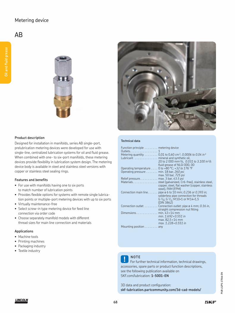
68
PU
B L
S/P
1 1
7046 E
N
Oil a
nd flu
id g
rease
Product description
Designed for installation in manifolds, series AB single-port,
prelubrication metering devices were developed for use with
single-line, centralized lubrication systems for oil and fluid grease.
When combined with one- to six-port manifolds, these metering
devices provide flexibility in lubrication system design. The metering
device body is available in steel and stainless steel versions with
copper or stainless steel sealing rings.
Features and benefits
• For use with manifolds having one to six ports
to match number of lubrication points
• Provides flexible options for systems with remote single lubrica-
tion points or multiple-port metering devices with up to six ports
• Virtually maintenance-free
• Select screw-in type metering device for feed line
connection via order code
• Choose separately manifold models with different
thread sizes for main line connection and materials
Applications
• Machine tools
• Printing machines
• Packaging industry
• Textile industry
Technical data
Function principle . . . . . . . . metering deviceOutlets. . . . . . . . . . . . . . . . . 1Metering quantity . . . . . . . . 0,01 to 0,60 cm 3, 0.0006 to 0.04 in³Lubricant . . . . . . . . . . . . . . mineral and synthetic oil,
20 to 2 000 mm²/s, 0.031 to 3.100 in²/s fluid grease of NLGI 000, 00
Operating temperature . . . . 0 to +80 °C; +32 to 176 °F Operating pressure . . . . . . . min. 18 bar, 260 psi
max. 50 bar, 725 psiRelief pressure. . . . . . . . . . . max. 3 bar, 43.5 psiMaterials . . . . . . . . . . . . . . . steel (galvanized, Cr6-free), stainless steel,
copper, steel, flat washer (copper, stainless steel), FKM (FPM)
Connection main line . . . . . . pipe ø 6 to 10 mm; 0.236 or 0.393 in; solderless pipe connection for threads G 1/8; G 1/4; M 10×1 or M 14×1,5 (DIN 3862)
Connection outlet . . . . . . . . Connection outlet: pipe ø 4 mm; 0.16 in, straight compression nut fitting
Dimensions . . . . . . . . . . . . . min. 43 × 14 mm min. 1.692 × 0.551 in max. 82,5 × 14 mm max. 1.228 × 0.551 in
Mounting position . . . . . . . . any
!NOTE
For further technical information, technical drawings,
accessories, spare parts or product function descriptions,
see the following publication available on
SKF.com/lubrication: 1-5001-EN
3D data and product configuration:
skf-lubrication.partcommunity.com/3d-cad-models/
Metering device
AB
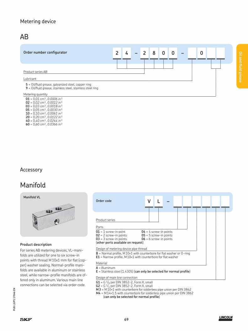
69
PU
B L
S/P
1 1
7046 E
N
Oil a
nd flu
id g
rease
Order number configurator 2 4 – 2 8 0 0 – 0
Product series AB
Lubricant
5 = Oil/fluid grease, galvanized steel, copper ring9 = Oil/fluid grease, stainless steel, stainless steel ring
Metering quantity
01 = 0,01 cm³, 0.0006 in³02 = 0,02 cm³, 0.0012 in³03 = 0,03 cm³, 0.0018 in³05 = 0,05 cm³, 0.0030 in³10 = 0,10 cm³, 0.0061 in³20 = 0,20 cm³, 0.0122 in³40 = 0,40 cm³, 0.0244 in³60 = 0,60 cm³, 0.0366 in³
Metering device
AB
Accessory
Manifold
Manifold VLOrder code V L –
Product series
Ports
01 = 1 screw-in point02 = 2 screw-in points03 = 3 screw-in points
04 = 4 screw-in points05 = 5 screw-in points06 = 6 screw-in points
(other ports available on request)
Design of metering device pipe thread
B = Normal profile, M 10×1 with counterbore for flat washer or O-ring E1 = Narrow profile, M 10×1 with counterbore for flat washer
Material
A = AluminumE = Stainless steel (1.4305) (can only be selected for normal profile)
Design of main line connection
G1 = G 1/8 per DIN 3852-2, Form X, smallG2 = G 1/4 per DIN 3852-2, Form X, smallM 3 = M 10×1 with counterbore for solderless pipe union per DIN 3862M4 = M 14×1.5 with counterbore for solderless pipe union per DIN 3862 (can only be selected for normal profile)
Product description
For series AB metering devices, VL-mani-
folds are utilized for one to six screw-in
points with thread M 10x1 mm for flat (cop-
per) washer sealing. Normal-profile mani-
folds are available in aluminum or stainless
steel, while narrow-profile manifolds are of-
fered only in aluminum. Various main line
connections can be selected via order code.

70
PU
B L
S/P
1 1
7046 E
N
Oil a
nd flu
id g
rease
Product description
Developed for use with single-line, centralized lubrication systems
for fluid grease, series VN relubrication metering devices are offered
with two, four or six ports. These metering devices were designed
for installation directly on the vehicle or construction machine re-
quiring lubrication. Series VN metering devices can be ordered with
fittings for the main line connection via the appropriate order code.
Features and benefits
• Choose metering device with two, four or six points
to match number of lubrication points
• Designed for installation directly on the vehicle/machine
requiring lubrication
• Select metering nipples and push-in or screw-in type
fittings for feed line or main line connections
• Easy metering adjustment by replacing metering nipples
• Black-coloured surface for optimized corrosion protection
Applications
• Commercial vehicles
• Construction machinery
Technical data
Function principle . . . . . . . . . . . metering deviceOutlets. . . . . . . . . . . . . . . . . . . . 2, 4 or 6Metering quantity . . . . . . . . . . . 0,05 to 1,00 cm³
0.003 to 0.061 in³Lubricant . . . . . . . . . . . . . . . . . fluid grease of NLGI 000, 00Operating temperature . . . . . –25 to +80 °C; –13 to +176 °F Operating pressure . . . . . . . . . . min. 20 bar; 290 psi
max. 80 bar; 1160 psiRelief pressure. . . . . . . . . . . . . . ≤1 bar, ≤14.5 psiMaterials . . . . . . . . . . . . . . . . . . zinc die-cast, brass, steel, flat washer
(copper), NBR Connection main line . . . . . . . . . different fittings for pipe ø 6 to 10 mm;
0.236 to 0.393 in or closure plugs for thread M8x1
Connection outlet . . . . . . . . . . . pipe ø 4 mm metering nipple (VS) with SKF Quick Connector - metering nipple (00) for solderless pipe connection
Dimensions . . . . . . . . . . . . . . . . min. 62 × 83,5 × 52 mm max. 130,5 × 83,5 × 58 mmmin. 2.440 × 3.287 × 2.047 inmax. 5.118 × 3.287 × 2.283 in
Mounting position . . . . . . . . . . . any
!NOTE
For further technical information, technical drawings,
accessories, spare parts or product function descriptions,
see the following publication available on
SKF.com/lubrication: 1-5001-EN
3D data and product configuration:
skf-lubrication.partcommunity.com/3d-cad-models/
Metering device
VN

71
PU
B L
S/P
1 1
7046 E
N
Oil a
nd flu
id g
rease
Order number configurator V N – 0 – –
Met
erin
g poi
nt 1
Met
erin
g poi
nt 2
Met
erin
g poi
nt 3
(0 =
not
pre
sent, o
n V
N2)
Met
erin
g poi
nt 4
(0 =
not
pre
sent, o
n V
N2)
Met
erin
g poi
nt 5
(0 =
not
pre
sent, o
n V
N2/4
)
Met
erin
g poi
nt 6
(0 =
not
pre
sent, o
n V
N2/4
)
Product series
Number of metering points (2, 4, 6)
Lubrication line fitting
00 = Solderless pipe connectionVS = SKF Quick Connector
Metering quantity
1 = 0,05 cm³, 0.003 in³2 = 0,10 cm³, 0.006 in³3 = 0,20 cm³, 0.012 in³4 = 0,30 cm³, 0.018 in³
5 = 0,40 cm³, 0.024 in³6 = 0,60 cm³, 0.036 in³7 = 1,00 cm³, 0.061 in³
Fittings for main line connection
A = Solderless pipe connection ø 8 mm, 0.315 inE = Solderless pipe connection ø 6 mm, 0.236 inH = Screw plug with flat washer S = SKF Quick Connector ø 10 mm, 0.01 inZ = Without fitting
Metering device
VN
SKF Quick Connector
Solderless pipe connection
Accessory
Exchangeable metering nipples
Order numbers for metering nipples 1) (replaceable)
Outlet øMaterial Elastomer
Metering quantity
mm in0,05 cm³0.003 in³
0,10 cm³0.006 in³
0,20 cm³0.012 in³
0,30 cm³0.018 in³
0,40 cm³0.024 in³
0,60 cm³0.036 in³
1,00 cm³0.061 in³
4 0.16 NBR VKU005-K VKU010-K VKU020-K VKU030-K VKU040-K VKU060-K VKU100-K
1) Metering nipples are made of brass.
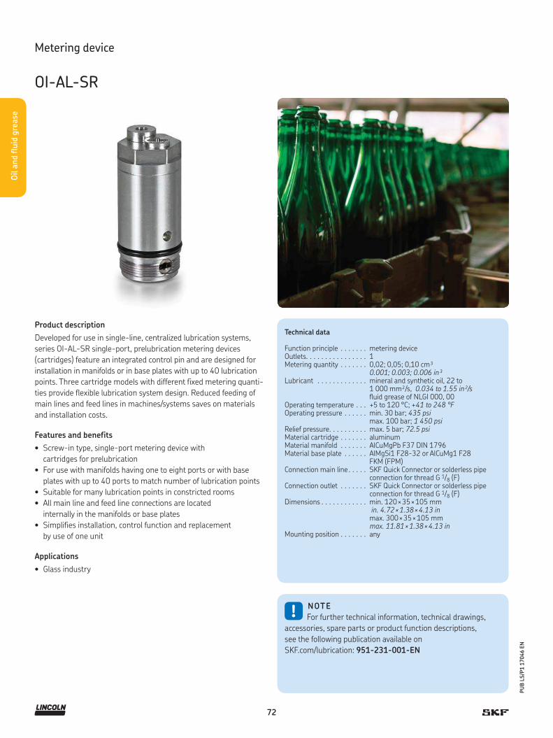
72
PU
B L
S/P
1 1
7046 E
N
Oil a
nd flu
id g
rease
Metering device
OI-AL-SR
Product description
Developed for use in single-line, centralized lubrication systems,
series OI-AL-SR single-port, prelubrication metering devices
(cartridges) feature an integrated control pin and are designed for
installation in manifolds or in base plates with up to 40 lubrication
points. Three cartridge models with different fixed metering quanti-
ties provide flexible lubrication system design. Reduced feeding of
main lines and feed lines in machines/systems saves on materials
and installation costs.
Features and benefits
• Screw-in type, single-port metering device with
cartridges for prelubrication
• For use with manifolds having one to eight ports or with base
plates with up to 40 ports to match number of lubrication points
• Suitable for many lubrication points in constricted rooms
• All main line and feed line connections are located
internally in the manifolds or base plates
• Simplifies installation, control function and replacement
by use of one unit
Applications
• Glass industry
Technical data
Function principle . . . . . . . metering deviceOutlets. . . . . . . . . . . . . . . . 1Metering quantity . . . . . . . 0,02; 0,05; 0,10 cm³
0.001; 0.003; 0.006 in³ Lubricant . . . . . . . . . . . . . mineral and synthetic oil, 22 to
1 000 mm²/s, 0.034 to 1.55 in²/s fluid grease of NLGI 000, 00
Operating temperature . . . +5 to 120 °C; +41 to 248 °FOperating pressure . . . . . . min. 30 bar; 435 psi
max. 100 bar; 1 450 psiRelief pressure. . . . . . . . . . max. 5 bar; 72.5 psiMaterial cartridge . . . . . . . aluminum Material manifold . . . . . . . AlCuMgPb F37 DIN 1796Material base plate . . . . . . AlMgSi1 F28-32 or AlCuMg1 F28
FKM (FPM)Connection main line . . . . . SKF Quick Connector or solderless pipe
connection for thread G 1/8 (F)Connection outlet . . . . . . . SKF Quick Connector or solderless pipe
connection for thread G 1/8 (F)Dimensions . . . . . . . . . . . . min. 120 × 35 × 105 mm
in. 4.72 × 1.38 × 4.13 inmax. 300 × 35 × 105 mm max. 11.81 × 1.38 × 4.13 in
Mounting position . . . . . . . any
!NOTE
For further technical information, technical drawings,
accessories, spare parts or product function descriptions,
see the following publication available on
SKF.com/lubrication: 951-231-001-EN

73
PU
B L
S/P
1 1
7046 E
N
Oil a
nd flu
id g
rease
Metering device
OI-AL-SR
Manifold OI-AL-SR Cartridge OI-AL-SR Base plate OI-AL-SR
Manifolds
Order number Number of ports
447-71901-1 2447-71902-1 3447-71903-1 4447-71904-1 5447-71905-1 6447-71906-1 8
Cartridges
Order number Metering quantity
547-33924-1 0,02 cm³/stroke547-33925-1 0,05 cm³/stroke547-33926-1 0,10 cm³/stroke
Base plate
Order number Number of ports
447-71899-1 40
Accessories
Cartridges, manifolds, base plates
Complete metering devices
Order number Number of outlets
Metering quantity
Outlet 1 Outlet 2 Outlet 3 Outlet 4 Outlet 5 Outlet 6 Outlet 7 Outlet 8
cm³ in³ cm³ in³ cm³ in³ cm³ in³ cm³ in³ cm³ in³ cm³ in³ cm³ in³
647-41151-2 2 0,02 0.001 0,02 0.001 – – – – – – – – – – – –647-41152-2 3 0,02 0.001 0,02 0.001 0,02 0.001 – – – – – – – – – –647-41152-4 3 0,10 0.006 0,05 0.003 0,05 0.003 – – – – – – – – – –647-41153-2 4 0,05 0.003 0,05 0.003 0,05 0.003 – – – – – – – – – –647-41154-4 5 0,02 0.001 0,02 0.001 0,02 0.001 0,02 0.001 0,02 0.001 – – – – – –647-41154-5 5 0,02 0.001 0,02 0.001 0,02 0.001 0,02 0.001 – – – – – – – –647-41154-7 5 0,02 0.001 0,05 0.003 0,05 0.003 0,05 0.003 0,05 0.003 – – – – – –647-41154-6 5 0,05 0.003 0,05 0.003 0,05 0.003 0,05 0.003 – – – – – – – –647-41155-2 6 0,10 0.006 0,05 0.003 0,05 0.003 0,05 0.003 0,05 0.003 0,05 0.003 – – – –647-41156-2 8 0,05 0.003 0,05 0.003 0,05 0.003 0,05 0.003 0,02 0.001 0,02 0.001 0,02 0.001 – –
Cartridge Manifold Base plates
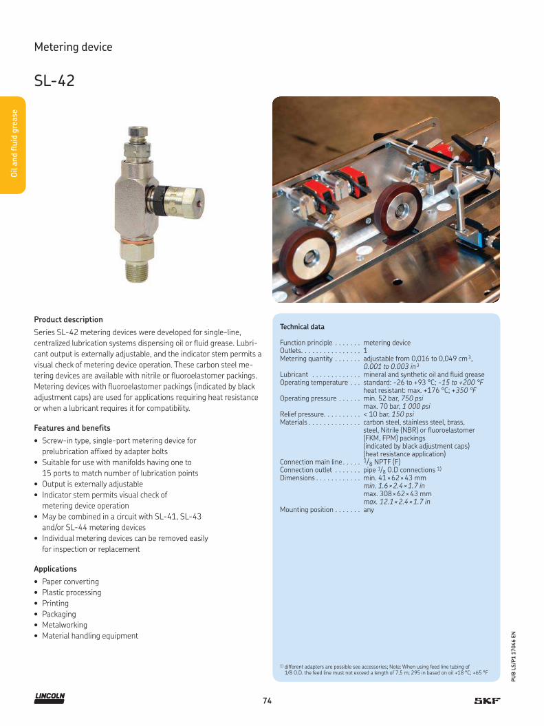
74
PU
B L
S/P
1 1
7046 E
N
Oil a
nd flu
id g
rease
Metering device
SL-42
Product description
Series SL-42 metering devices were developed for single-line,
centralized lubrication systems dispensing oil or fluid grease. Lubri-
cant output is externally adjustable, and the indicator stem permits a
visual check of metering device operation. These carbon steel me-
tering devices are available with nitrile or fluoroelastomer packings.
Metering devices with fluoroelastomer packings (indicated by black
adjustment caps) are used for applications requiring heat resistance
or when a lubricant requires it for compatibility.
Features and benefits
• Screw-in type, single-port metering device for
prelubrication affixed by adapter bolts
• Suitable for use with manifolds having one to
15 ports to match number of lubrication points
• Output is externally adjustable
• Indicator stem permits visual check of
metering device operation
• May be combined in a circuit with SL-41, SL-43
and/or SL-44 metering devices
• Individual metering devices can be removed easily
for inspection or replacement
Applications
• Paper converting
• Plastic processing
• Printing
• Packaging
• Metalworking
• Material handling equipment
Technical data
Function principle . . . . . . . metering deviceOutlets. . . . . . . . . . . . . . . . 1Metering quantity . . . . . . . adjustable from 0,016 to 0,049 cm 3,
0.001 to 0.003 in³Lubricant . . . . . . . . . . . . . mineral and synthetic oil and fluid greaseOperating temperature . . . standard: -26 to +93 °C; -15 to +200 °F
heat resistant: max. +176 °C; +350 °FOperating pressure . . . . . . min. 52 bar, 750 psi
max. 70 bar, 1 000 psi Relief pressure. . . . . . . . . . < 10 bar, 150 psiMaterials . . . . . . . . . . . . . . carbon steel, stainless steel, brass,
steel, Nitrile (NBR) or fluoroelastomer (FKM, FPM) packings (indicated by black adjustment caps) (heat resistance application)
Connection main line . . . . . 1/8 NPTF (F)Connection outlet . . . . . . . pipe 1/8 O.D connections 1) Dimensions . . . . . . . . . . . . min. 41 × 62 × 43 mm
min. 1.6 × 2.4 × 1.7 inmax. 308 × 62 × 43 mm max. 12.1 × 2.4 × 1.7 in
Mounting position . . . . . . . any
1) different adapters are possible see accessories; Note: When using feed line tubing of 1/8 O.D. the feed line must not exceed a length of 7,5 m; 295 in based on oil +18 °C; +65 °F

75
PU
B L
S/P
1 1
7046 E
N
Oil a
nd flu
id g
rease
Order number configurator –
Product series
83311 = standard with nitrile packings84428 = heat resistant with fluoroelastomer packings 85352 = standard with nitrile packings for metric tube connection O.D. 4 and 6 mm, up to 6 outlets
Number of metering devices
1 = 1 metering device, mounted in a manifold2 = 2 metering devices, mounted in a manifold3 = 3 metering devices, mounted in a manifold4 = 4 metering devices, mounted in a manifold5 = 5 metering devices, mounted in a manifold6 = 6 metering devices, mounted in a manifold10 = 10 metering devices, mounted in a manifold15 = 15 metering devices, mounted in a manifold
Metering device
SL-42
Replacement for manifold injectors
Order number Designation
83535 standard single metering device/no manifold, 1 outlet, 1/8 NPTF (M) inlet
83313 metering device for standard manifold
84048 metering device for heat-resistant manifold
249649 metric replacement injector
Accessories
Metering devices, manifolds and adapters
Metering devices
Manifolds
Order number 1) Number of ports
91863-1 191864-1 291865-1 391866-1 414361 591976-1 614312 1014253 15
1) Injectors except replacement injectors for manifold, include compression nut and ferrule for tubing 1/8 in O.D. as standard. Injectors with manifolds include two mounting clips and screws.
Manifolds Adapters
G 1/8 to metric fitting adapters
Order number Pipe ø mm
Material
249281 4 steel249279 4 stainless steel
249282 6 steel249280 6 stainless steel
This picture shows a manifold example. Please note, thatthe real manifold differs in terms of size and design.
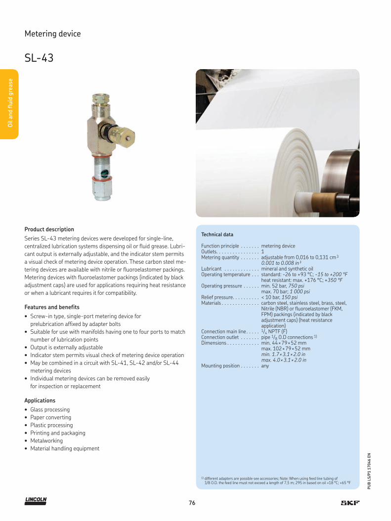
76
PU
B L
S/P
1 1
7046 E
N
Oil a
nd flu
id g
rease
Product description
Series SL-43 metering devices were developed for single-line,
centralized lubrication systems dispensing oil or fluid grease. Lubri-
cant output is externally adjustable, and the indicator stem permits
a visual check of metering device operation. These carbon steel me-
tering devices are available with nitrile or fluoroelastomer packings.
Metering devices with fluoroelastomer packings (indicated by black
adjustment caps) are used for applications requiring heat resistance
or when a lubricant requires it for compatibility.
Features and benefits
• Screw-in type, single-port metering device for
prelubrication affixed by adapter bolts
• Suitable for use with manifolds having one to four ports to match
number of lubrication points
• Output is externally adjustable
• Indicator stem permits visual check of metering device operation
• May be combined in a circuit with SL-41, SL-42 and/or SL-44
metering devices
• Individual metering devices can be removed easily
for inspection or replacement
Applications
• Glass processing
• Paper converting
• Plastic processing
• Printing and packaging
• Metalworking
• Material handling equipment
Technical data
Function principle . . . . . . . metering deviceOutlets. . . . . . . . . . . . . . . . 1Metering quantity . . . . . . . adjustable from 0,016 to 0,131 cm 3
0.001 to 0.008 in³Lubricant . . . . . . . . . . . . . mineral and synthetic oilOperating temperature . . . standard: -26 to +93 °C; -15 to +200 °F
heat resistant: max. +176 °C; +350 °FOperating pressure . . . . . . min. 52 bar, 750 psi
max. 70 bar; 1 000 psiRelief pressure. . . . . . . . . . < 10 bar, 150 psiMaterials . . . . . . . . . . . . . . carbon steel, stainless steel, brass, steel,
Nitrile (NBR) or fluoroelastomer (FKM, FPM) packings (indicated by black adjustment caps) (heat resistance application)
Connection main line . . . . . 1/4 NPTF (F)Connection outlet . . . . . . . pipe 1/8 O.D connections 1)
Dimensions . . . . . . . . . . . . min. 44 × 79 × 52 mmmax. 102 × 79 × 52 mmmin. 1.7 × 3.1 × 2.0 inmax. 4.0 × 3.1 × 2.0 in
Mounting position . . . . . . . any
Metering device
SL-43
1) different adapters are possible see accessories; Note: When using feed line tubing of 1/8 O.D. the feed line must not exceed a length of 7,5 m; 295 in based on oil +18 °C; +65 °F

77
PU
B L
S/P
1 1
7046 E
N
Oil a
nd flu
id g
rease
Order number configurator –
Product series
83661 = standard with nitrile packings 84429 = heat resistant with fluoroelastomer packings
Number of metering devices
1 = 1 metering device, mounted in a manifold2 = 2 metering devices, mounted in a manifold3 = 3 metering devices, mounted in a manifold4 = 4 metering devices, mounted in a manifold
Metering device
SL-43
Replacement for manifold injectors
Order number Designation
83662 standard single metering device/no manifold, 1 outlet, 1/8 NPTF (M) inlet
83660 metering device for standard manifold
84110 metering device for heat-resistant manifold
Accessories
Metering devices, manifolds and adapters
Metering devices
Manifolds
Order number 1) Number of ports
91883-1 1 91884-1 291885-1 391886-1 4
1) Injectors except replacement injectors for manifold, include compression nut and ferrule for tubing 1/8 in O.D. as standard. Injectors with manifolds include two mounting clips and screws.
Manifolds Adapters
G 1/8 to metric fitting adapters
Order number Pipe ø mm
Material
249281 4 steel249279 4 stainless steel
249282 6 steel249280 6 stainless steel
This picture shows a manifold example. Please note, thatthe real manifold differs in terms of size and design.

78
PU
B L
S/P
1 1
7046 E
N
Oil a
nd flu
id g
rease
Product description
Series SL-41 metering devices are designed for use in high-tem-
perature applications, depending on the lubricant. These metering
devices are available installed only in manifolds with 3/8-inch NPT
female inlets and feature a tamper-resistant adjustment screw that
does not incorporate a visual indicator.
Features and benefits
• Screw-in type, single-port metering device
affixed by adapter bolts
• Suitable for use with manifolds having one to
five ports to match number of lubrication points
• Output is externally adjustable.
• Individual injectors can be removed easily for
inspection or replacement
• Carbon steel with fluoroelastomer packings
Applications
• Glass processing
• Metalworking
Technical data
Function principle . . . . . . . metering deviceOutlets. . . . . . . . . . . . . . . . 1 to 5Metering quantity . . . . . . . adjustable from 0,13 to 1,31 cm 3
0.008 to 0.0689 in³Lubricant . . . . . . . . . . . . . mineral and synthetic oilOperating temperature . . . standard: -26 to +93 °C; -15 to 200 °F
heat resistant: max. +176 °C; +350 °FOperating pressure . . . . . . min. 52 bar, 750 psi
max. 70 bar; 1 000 psiRelief pressure. . . . . . . . . . < 10 bar, 150 psiMaterials . . . . . . . . . . . . . . carbon steel, FKM (FPM) Connection main line . . . . . 3/8 NPTF (F)Connection outlet . . . . . . . 1/8 NPTF (F) 1)
Dimensions . . . . . . . . . . . . min. 63 × 163,5 × 52,4 mmmin. 2.5 × 6.4 × 2.1 inmax. 171 × 163,5 × 52,4 mmmax. 6.75 × 6.4 × 2.1 in
Mounting position . . . . . . . any
Metering device
SL-41
1) When using feed line tubing of 1/8 O.D. the feed line must not exceed a length of 7,5 m; 295 in based on oil +18 °C; +64 °F 1/8 NPTF (F). When using feed line tubing of 1/8 O.D. the feed line must not exceed a length of 7,5 m; 295 in based on oil +18 °C; +64 °F

79
PU
B L
S/P
1 1
7046 E
N
Oil a
nd flu
id g
rease
Order number configurator 8 2 2 9 4 –
Product series
82294 = heat resistant with fluoroelastomer packings
Number of metering devices
1 = 1 metering device, mounted in a manifold2 = 2 metering devices, mounted in a manifold3 = 3 metering devices, mounted in a manifold4 = 4 metering devices, mounted in a manifold5 = 5 metering devices, mounted in a manifold
Metering device
SL-41
Replacement for manifold injectors
Order number Designation
82295 metering device for manifold NPTF (F)
82292 single metering device
Accessories
Metering devices and manifolds
Metering devices
Manifolds
Order number 1) Number of ports
12658 111962 211963 311964 411965 5
1) Each injector has two outlets. One is closed by a closure plug, but can be used to increase outlet quantity combined with another injector.
Manifolds
This picture shows a manifold example. Please note, thatthe real manifold differs in terms of size and design.
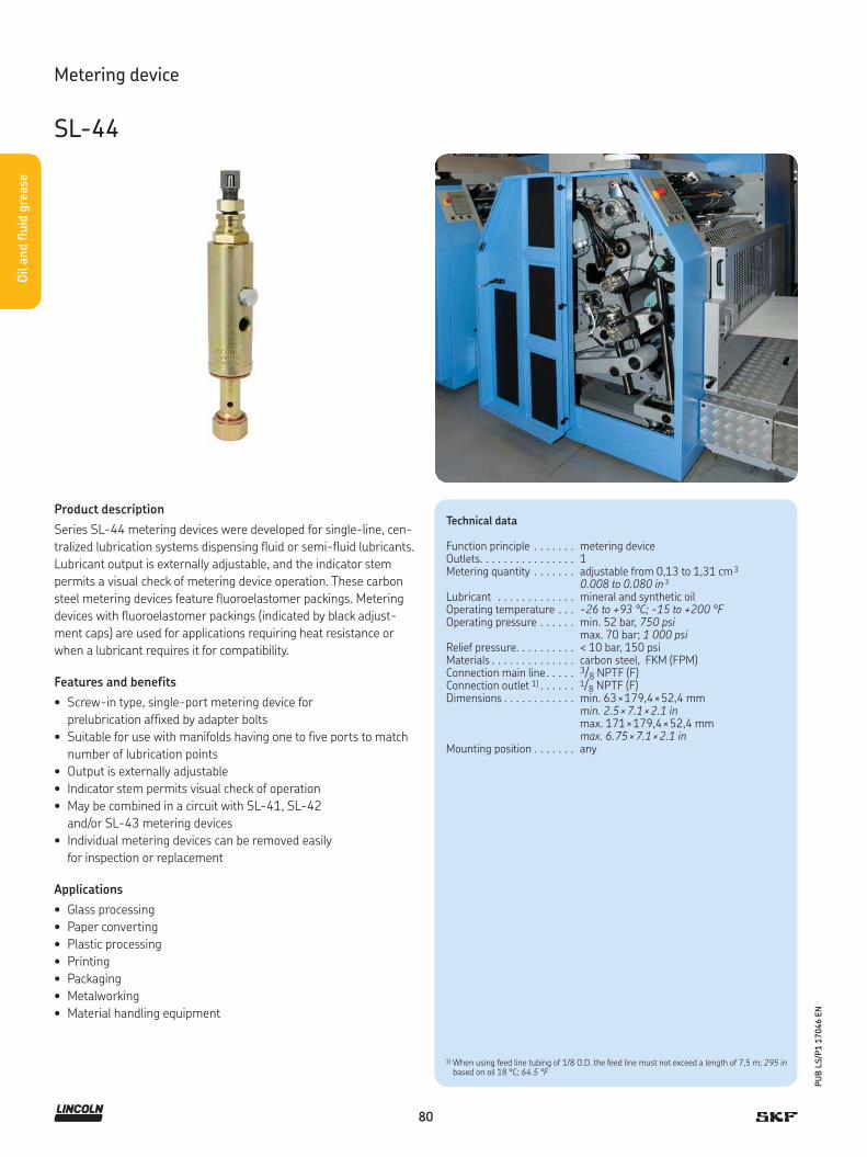
80
PU
B L
S/P
1 1
7046 E
N
Oil a
nd flu
id g
rease
Product description
Series SL-44 metering devices were developed for single-line, cen-
tralized lubrication systems dispensing fluid or semi-fluid lubricants.
Lubricant output is externally adjustable, and the indicator stem
permits a visual check of metering device operation. These carbon
steel metering devices feature fluoroelastomer packings. Metering
devices with fluoroelastomer packings (indicated by black adjust-
ment caps) are used for applications requiring heat resistance or
when a lubricant requires it for compatibility.
Features and benefits
• Screw-in type, single-port metering device for
prelubrication affixed by adapter bolts
• Suitable for use with manifolds having one to five ports to match
number of lubrication points
• Output is externally adjustable
• Indicator stem permits visual check of operation
• May be combined in a circuit with SL-41, SL-42
and/or SL-43 metering devices
• Individual metering devices can be removed easily
for inspection or replacement
Applications
• Glass processing
• Paper converting
• Plastic processing
• Printing
• Packaging
• Metalworking
• Material handling equipment
Technical data
Function principle . . . . . . . metering deviceOutlets. . . . . . . . . . . . . . . . 1Metering quantity . . . . . . . adjustable from 0,13 to 1,31 cm 3
0.008 to 0.080 in³Lubricant . . . . . . . . . . . . . mineral and synthetic oilOperating temperature . . . -26 to +93 °C; -15 to +200 °FOperating pressure . . . . . . min. 52 bar, 750 psi
max. 70 bar; 1 000 psiRelief pressure. . . . . . . . . . < 10 bar, 150 psiMaterials . . . . . . . . . . . . . . carbon steel, FKM (FPM) Connection main line . . . . . 3/8 NPTF (F)Connection outlet 1) . . . . . . 1/8 NPTF (F) Dimensions . . . . . . . . . . . . min. 63 × 179,4 × 52,4 mm
min. 2.5 × 7.1 × 2.1 inmax. 171 × 179,4 × 52,4 mmmax. 6.75 × 7.1 × 2.1 in
Mounting position . . . . . . . any
Metering device
SL-44
1) When using feed line tubing of 1/8 O.D. the feed line must not exceed a length of 7,5 m; 295 in based on oil 18 °C; 64.5 °F

81
PU
B L
S/P
1 1
7046 E
N
Oil a
nd flu
id g
rease
Order number configurator 8 3 7 4 9 –
Product series
83749 = heat resistant with fluoroelastomer packings
Number of metering devices
1 = 1 metering device, mounted in a manifold2 = 2 metering devices, mounted in a manifold3 = 3 metering devices, mounted in a manifold4 = 4 metering devices, mounted in a manifold5 = 5 metering devices, mounted in a manifold
Metering device
SL-44
Replacement for manifold injectors
Order number Designation
83748 metering device for manifold NPTF (F)
Accessories
Metering devices and manifolds
Metering devices
Manifold
Order number 1) Number of ports
12658 1 11962 211963 311964 411965 5
1) Each injector has two outlets. One is closed by a closure plug, but can be used to increase outlet quantity combined with another injector.
Manifolds
This picture shows a manifold example. Please note, thatthe real manifold differs in terms of size and design.

82
PU
B L
S/P
1 1
7046 E
N
Gre
ase
System description
Regardless of the application, the principle
of single-line lubrication remains the same:
a central pump station automatically deliv-
ers lubricant through a single supply line to
the lubricant metering device. Each meter-
ing device serves only one lubrication point
and may be adjusted to deliver the precise
amount of grease or oil required. Systems
can service one machine, different zones on
one machine or even several separate
machines.
All single-line systems include a pump,
injectors, controller and a pressure switch /
transducer. These components are very easy
to install and modify on any application as
needed.
SKF offers two brands of single line paral-
lel lubrication systems: the Lincoln Centro-
Matic and the SKF MonoFlex. These systems
are recognized world wide for their reliability
to lubricate in adverse conditions in virtually
any application.
For planning a lubrication system, condi-
tions the system will be used in need to be
determined first. The number of lubrication
points, back pressures at the lubrication
points, operating temperature range, lubri-
cant, the feed pump’s drive energy, control
and monitoring etc. need to be defined
correctly.
Attention to information on bearing or lu-
brication point specifications need to be paid
too. The sum of all the quantities metered
out by the system’s metering devices needs
to be completed by safety margin and com-
pressibility loss. SKF application engineers,
as well as SKF sales partners and distribu-
tors, are experts in laying out lubrication
systems according to all these specifications.
A lubrication system laid out by SKF and
partners ensures the supply of the correct
amount of lubricant at the best time to lu-
bricate. This reduces wear and it avoids pol-
lution caused by over-lubrication.
Advantages of a single-line
lubrication system:
• Easy to understand, install and maintain
• Fully adjustable or customizable for
any application
• Suitable for almost all lubricants
• Simple system expansion
• System continues to operate if one point
becomes blocked
• Integrated system control and monitoring
• Able to pump long distances within a wide
temperature range
Single-line lubrication systems for grease
83
PU
B L
S/P
1 1
7046 E
N
Grea
seSystem and applications
Applications
Mining applications have been installed
in the far north including the Oil Sands of
Canada and Siberia and in the hot deserts
of Africa and Australia. Major food, beverage,
oil/gas, cement, steel, construction and rail
customers also rely on SKF’s single-line
products. All single-line applications benefit
from SKF’s method of delivering precise
amounts of lubricant at controlled intervals
to the lubrication point.
• Mining
• On/Off-road
• Construction machinery
• Cement industry
• Food and beverage
• Machine tools
• Railroad
• Forestry
• Steel
• And more
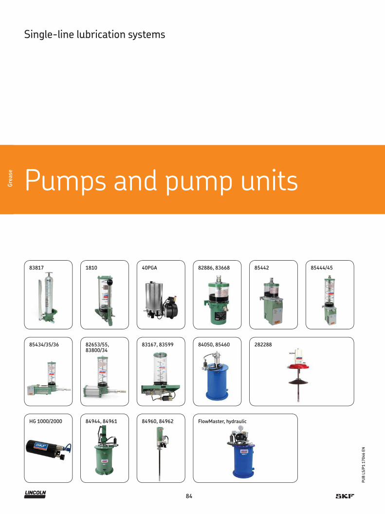
40PGA 82886, 83668 85442 85444/45
85434/35/36
83817 1810
82653/55, 83800/34
83167, 83599 84050, 85460 282288
84
PU
B L
S/P
1 1
7046 E
N
Gre
ase
Pumps and pump unitsGre
ase
Single-line lubrication systems
HG 1000/2000 84944, 84961 84960, 84962 FlowMaster, hydraulic

85
PU
B L
S/P
1 1
7046 E
N
Grea
se
Overview of grease pumps and pump units
Manually operated pumps and pump units
Product Lubricant Metering quantity Reservoir Metering Remarks Pagegrease max. deviceNLGI category 1)
0 1 2 cm 3/ stroke in3/ stroke kg lb
83817 • • • 1,6 0.09 0,5 1 5, 6, 7 multiple stroke possible 881810 • • • 2,6 0.16 2,3 5 5, 6, 7 multiple stroke possible 89
1) Select the recommended fittings, adjust the pump pressure within the recommended metering device pressure range
Hydraulically operated pumps and pump units
Product Lubricant Metering quantity Reservoir Metering Remarks Pagegrease max. deviceNLGI category 1)
0 1 2 cm 3/ stroke in3/ stroke kg lb
HG 1000/2000 • • – 0–1 000(0–2 000)
0–61.02(0–122)
1,0; 2,0 2.2; 4.4 4, 5 single stroke 101
0 1 2 cm 3/ min in3/ min kg lb
84944, 84961 • • • 180 11 30 5, 6, 7 reciprocating 10284960, 84962 • • • 180 11 – – 5, 6, 7 reciprocating drum 103FlowMaster • • • 115–737 7–45 16; 27; 41;
54; 18035; 60; 90; 120; 400
5, 6, 7 drum, solenoid, 24 V DC 104
1) Select the recommended fittings, adjust the pump pressure within the recommended metering device pressure range2) Controller included or optional
Air–operated pumps and pump units
Product Lubricant Metering quantity Reservoir Metering Remarks Pagegrease max. deviceNLGI category 1)
0 1 2 cm 3/ stroke in3/ stroke kg lb
40PGA • • • 40 2.44 1,7; 2; 4; 10 3.7; 4.4; 8.8; 22 5, 6, 7 single stroke 9082886, 83668 • • • 7,4 0.45 0,5; 2,0 1; 4.4 5, 6, 7 single stroke 9285442 2) • • • 7,4 0.45 0,5 1 5, 6, 7 single stroke, 120 V AC 9385444/45 2) • • • 7,4 0.45 1,8 4 5, 6, 7 single stroke, 120/240 V AC 9485434/35/36 2) • • • 18,7; 35,2 1.14; 2.15 2,0 4.5 5, 6, 7 single stroke, 120/240 V AC 9582653/55 • • • 22,9 1.39 2,0 4.5 5, 6, 7 single stroke, 120/240 V AC 9683800/34 • • • 35,2 2.15 2,0 4.5 5, 6, 7 single stroke, 120/240 V AC 96
0 1 2 cm 3/ min in3/ min kg lb
83167 • • • 197 12 5,0 11 5, 6, 7 reciprocating 9783599 • • • 197 12 5,0 11 5, 6, 7 reciprocating 9884050, 85460 • • • 492 30 27 60 5, 6, 7 reciprocating 99282288 2) • • • 492 30 55 120 5, 6, 7 reciprocating drum, 120 V AC 100
1) Select the recommended fittings, adjust the pump pressure within the recommended metering device pressure range2) Controller included or optional

86
PU
B L
S/P
1 1
7046 E
N
Gre
ase
Gre
ase
Single-line lubrication systems
Minilube
Multilube
P603S KFG
FK
P653S
FlowMaster, electric

87
PU
B L
S/P
1 1
7046 E
N
Grea
se
Overview of grease pumps and pump units
Electrically operated pumps and pump units
Product Lubricant Metering quantity Reservoir capacity Metering Remarks Pagegrease max. deviceNLGI category 1)
0 1 2 cm 3/ min in3/ min kg lb
P603S 2), 3) • • • 12 0.7 4; 8; 10; 15; 20 8.8; 18; 22; 33; 44 5, 6, 7 12/24 V DC 106
Minilube 2) • • – 13 0.8 2 4.4 5, 6, 7 12/24 V DC 108
KFG 2), 3) • • • 15 0.9 2; 4; 6; 8; 10; 12; 15; 20
4.4; 8.8; 13; 18;22; 26; 33; 44
5, 6, 7 12/24 V DC, 90…264 V AC 110
Multilube 2) • • – 16 0.976 4; 10 8.8; 22 5, 6, 7 24 V DC, 115/230 V AC 112
P653S 2), 3) • • • 24,6 1.5 4; 8; 15; 20 8.8; 18; 22; 44 5, 6, 7 24 V DC, 120/230 V AC 114
FK 2) • • • 74 4.5 15; 30; 60 22; 66; 132 5, 6, 7 3 phase drive 116
FlowMaster, electric
• • • 103 6.3 16, 25, 28, 35, 40, 55, 180
35, 55, 60, 78, 90, 120, 400
5, 6, 7 12/24 V DC; 120 to 460 V AC
118
1) Select the recommended fittings, adjust the pump pressure within the recommended metering device pressure range2) Controller included or optional3) Stainless steel or C5M available

88
PU
B L
S/P
1 1
7046 E
N
Gre
ase
Product description
This manual pump unit has a metal reservoir and a spring-loaded
follower. The indicator pin in the pump base shows when 172 bar
(2 500 psi) system operating pressure has been achieved.
Features and benefits
• Number of strokes dependent on connected
lubrication points and their dosage
• Metal reservoir with spring-loaded follower also suitable
for replaceable 400 g grease cartridges
• Simple handling
• Low-cost, efficient method of lubricant distribution
• Pump base with built-in check vent valve and indicator pin
for visual control of max. or vent pressure
• Vents when handle is pushed all the way back
• Two different filling couplers available
• For use with metering devices of category 5, 6, 7
Applications
• Construction machinery
• Agriculture
Technical data
Order number . . . . . . . . . . 83817Function principle . . . . . . . manually operated piston pumpOutlets. . . . . . . . . . . . . . . . 1Metering quantity . . . . . . . 1,6 cm 3/ stroke, 0.10 in3/ strokeLubricant. . . . . . . . . . . . . . grease NLGI 0, 1, 2Operating temperature . . . –20 to +65 °C;
–4 to +149 °FOperating pressure . . . . . . min. 82 bar, 1 200 psi
max. 240 bar, 3 500 psiReservoir. . . . . . . . . . . . . . 0,5 kg, 1 lbMaterial . . . . . . . . . . . . . . . steel, brass, copper,
polyurethane, nitrile Filling method . . . . . . . . . . 0,4 kg, 14.5 oz, grease cartridge/bulk fillConnection outlet . . . . . . . 1/8 NPTF (F)Dimensions . . . . . . . . . . . . 387 × 127 × 141 mm
15.25 × 5 × 5.625 inMounting position . . . . . . . vertical or horizontal
Pump unit
83817

89
PU
B L
S/P
1 1
7046 E
N
Grea
se
Product description
The Model 1810 pump unit features a translucent reservoir with
spring-loaded follower. The indicator pin in the pump base shows
when 172 bar (2 500 psi) system operating pressure has been
achieved. It can be refilled via the included fitting using the Model
81834 filler pump or other manual pumps equipped with a Model
645006 coupler.
Features and benefits
• Number of strokes dependent on connected
lubrication points and their dosage
• Reservoir with spring-loaded follower
• Simple handling
• Low-cost, efficient method of lubricant distribution
• Pump base with built-in check vent valve and indicator pin
for visual control of max. or vent pressure
• Vents when handle is pushed all the way back
• Two different filling couplers available
• For use with metering devices of category 5, 6, 7
Applications
• Construction machinery
• Agriculture
Technical data
Order number . . . . . . . . . . 1810Function principle . . . . . . . manually operated piston pumpOutlets. . . . . . . . . . . . . . . . 1Metering quantity . . . . . . . 2,6 cm 3/ stroke, 0.16 in3/ strokeLubricant. . . . . . . . . . . . . . grease NLGI 0, 1, 2Operating temperature . . . -20 to +65 °C; -4 to +149 °FOperating pressure . . . . . . min. 82 bar, 1 200 psi
max. 240 bar, 3 500 psiReservoir. . . . . . . . . . . . . . 2,3 kg, 5 lbMaterial . . . . . . . . . . . . . . . acrylic, steel, brass,
copper, polyurethane, nitrile Connection outlet . . . . . . . 1/4 NPTF (F)Dimensions . . . . . . . . . . . . 413 × 181 × 197 mm
16.25 × 7.125 × 7.75 inMounting position . . . . . . . vertical or horizontal
Pump unit
1810

90
PU
B L
S/P
1 1
7046 E
N
Gre
ase
!NOTE
For further technical information, technical drawings,
accessories, spare parts or product function descriptions,
see the following publication available on
SKF.com/lubrication: 11678 EN, 11390007_40PGA_01_EN
Technical data
Function principle . . . . . . . . . . . pneumatically operated piston pump
Outlet . . . . . . . . . . . . . . . . . . . . 1Metering quantity . . . . . . . . . . . 40 cm 3/ stroke
2.4 in3/ strokeLubricant. . . . . . . . . . . . . . . . . . grease NLGI 0, 1, 2Operating temperature . . . . . . . -20 to +65 °C
-4 to +150 °FOperating pressure . . . . . . . . . . max. 10 bar
145 psiReservoir. . . . . . . . . . . . . . . . . . 1,7; 2; 4 and 10 kg
3.75; 4.4; 8.8 and 22 lbMaterial . . . . . . . . . . . . . . . . . . . stainless steel, plastic, steel
and aluminumConnection outlet . . . . . . . . . . . R 1/4 inOperating voltage . . . . . . . . . . . 24 VTransmission ratio . . . . . . . . . . . 16:1Protection class . . . . . . . . . . . . . IP 65Dimensions (dep. on version). . . min. 270 × 320 × 180 mm
min. 10.63 × 12.59 × 7.0 inmax. 570 × 320 × 245 mmmax. 22.44 × 12.59 × 9.65 in
Mounting position . . . . . . . . . . . vertical and horizontally
Pump unit
40PGA
Product description
Pump Model 40PGA is a compact lubrication pump unit. The splash-
proof pump operates pneumatically and can be controlled and mon-
itored by the remote electric control unit ST-102 or ST-102P. The
pump is available with a choice of different kind of reservoir sizes
and materials, each featuring a spring-loaded intermediate piston.
A low-level alarm is available in aluminum and steel version and
pump is available with an integrated pressure switch.
Features and benefits
• Compact, air-operated lubrication pump unit for
demanding conditions
• Part of a modular and modifiable system
• Splash-proof pump is offered with:
- choice of four different reservoir sizes
- spring-loaded, intermediate piston in reservoir
- steel and aluminum reservoirs are equipped with
low level alarm
- optional an integrated pressure switch
• Mechanical relief valve
• Controlled and monitored by a remote timer continuously
• Safe and environmentally friendly
• For use with metering devices of category 5, 6 and 7
Applications
• Buses and trucks
• Vehicles

91
PU
B L
S/P
1 1
7046 E
N
Grea
se
Pump unit
40PGA
Order number configurator 40PGA – – – 24 – PS
Product series
40PGA = 40PGA Pump unit
Reservoir material
A = AluminiumP = PlasticS = Stainless steel
Reservoir volume
170 = 1,7 kg; 3.74 lb (plastic reservoir)2L = 2 kg; 4.4 lb (stainless steel reservoir)4L = 4 kg; 8.8 lb (aluminum reservoir)10L = 10 kg; 22 lb (aluminum reservoir)
Operating voltage
24 = 24 V DC
Pressure monitoring
PS = integrated pressure switch

92
PU
B L
S/P
1 1
7046 E
N
Gre
ase
Technical data
Order number . . . . . . . . . . 82886, 83668Function principle . . . . . . . pneumatically operated
psiton pump (single-stroke)Outlets. . . . . . . . . . . . . . . . 1Metering quantity . . . . . . . 7,4 cm 3/ stroke, 0.45 in3/ strokeLubricant. . . . . . . . . . . . . . grease NLGI 0, 1, 2Operating temperature . . . –18 to +65 °C; 0 to +150 °FOperating pressure . . . . . . min. 82 bar, 1 200 psi
max. 240 bar, 3 500 psiReservoir. . . . . . . . . . . . . . 0,5 or 2 kg; 1 or 4.4 lbMaterial . . . . . . . . . . . . . . . acrylicConnection outlet . . . . . . . 1/4 NPTF (F)Transmission ratio . . . . . . . 20:1Air inlet . . . . . . . . . . . . . . . 1/4 NPTF (F)Mounting position . . . . . . . vertical
Timer
On time . . . . . . . . . . . . . . . min. 10 sec; max. 1 min. 24 secCycle time . . . . . . . . . . . . . min. 20 sec; max. 24 hVoltage . . . . . . . . . . . . . . . 120 V AC, 60 Hz; 110 V AC, 50 HzOperating temperature . . . –23 to +65 °C; –10 to +150 °F
Pump unit
82886, 83668
Pumps
Order number
Reservoir capacity
Dimensions
kg lb mm in
82886 0,5 1 263 × 133 × 152 10.4 × 5.3 × 6.083668 2 4.4 470 × 133 × 152 18.5 × 5.3 × 6.0
Product description
All models are air-operated, positive-displacement pumps deliver-
ing a maximum volume by means of a single stroke of the pump.
Solenoid air valves and adjustable, solid-state time controls are in-
tegrated into the pump body, and translucent, acrylic reservoirs with
spring-loaded followers are available in several sizes. Integrated
controls feature LED indicators for “Power On”, “Pump On” and
“Alarm,” along with a membrane-type, “Manual Lube” switch. Pump
discharges lubricant on air-powered forward stroke and vents on
spring-powered return stroke through built-in check/vent valve.
Includes filler fitting for refilling reservoir with Model 81834 or
other manual pump equipped with Model 645006 coupler.
Features and benefits
• Remote system components such as 3/2-way valves,
adjustments for air power, and monitoring of pump and
system are available separately on request
• For use with metering devices of category 5, 6 and 7
Applications
• Cement industry
• Wood-working
• Food and beverage

93
PU
B L
S/P
1 1
7046 E
N
Grea
se
Product description
Model 85442 is an air-operated, positive-displacement pump
delivering a maximum volume by means of a single stroke of the
pump. Solenoid air valves and adjustable, solid-state time controls
are integrated into the pump body. This pump unit is designed to
deliver grease to single-line metering devices and includes a special
high-volume refill fitting. Acrylic reservoirs are available in several
sizes. Integrated controls feature LED indicators for “Power On”,
“Pump On” and “Alarm” along with a membrane-type, “Manual
Lube” switch.
Features and benefits
• Reservoir 0,45 kg / 1 lb with spring-loaded follower
• Integrated solenoid air valve
• High-volume refill fitting
• For use with metering devices of category 5, 6 and 7
Applications
• Cement industry
• Wood-working
• Food and beverage
Technical data
Order number . . . . . . . . . . . . . . . 85442Function principle . . . . . . . . . . . . pneumatically operated
piston pump (single-stroke)Outlets. . . . . . . . . . . . . . . . . . . . . 1Metering quantity . . . . . . . . . . . . 7,4 cm 3/ stroke, 0.45 in3/ strokeLubricant. . . . . . . . . . . . . . . . . . . grease NLGI 0, 1, 2Operating temperature . . . . . . . . –23 to +65 °C; –10 to +150 °FOperating pressure . . . . . . . . . . . min. 82 bar, 1 200 psi
max. 240 bar, 3 500 psiReservoir. . . . . . . . . . . . . . . . . . . 0,5 kg, 1.0 lbMaterial . . . . . . . . . . . . . . . . . . . . acrylicConnection outlet . . . . . . . . . . . . 1/4 NPTF (F)Voltage . . . . . . . . . . . . . . . . . . . . 120 V ACTransmission ratio . . . . . . . . . . . . 20:1Dimensions . . . . . . . . . . . . . . . . . 133 × 184 × 305 mm
5.25 × 7.24 × 12.02 inMounting position . . . . . . . . . . . . vertical
Timer and controller
On time . . . . . . . . . . . . . . . . . . . . 10 or 30 secOff time . . . . . . . . . . . . . . . . . . . . 1/2 to 30 min. or 30 min. to 30 hAlarm contacts . . . . . . . . . . . . . . 8 amps at 250 V ACOperating temperature . . . . . . . . –23 to +65 °C; –10 to +150 °F
Pump unit
85442
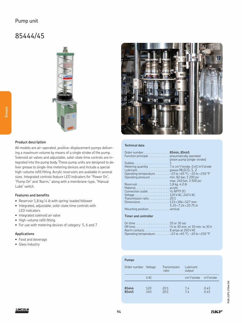
94
PU
B L
S/P
1 1
7046 E
N
Gre
ase
Product description
All models are air-operated, positive-displacement pumps deliver-
ing a maximum volume by means of a single stroke of the pump.
Solenoid air valves and adjustable, solid-state time controls are in-
tegrated into the pump body. These pump units are designed to de-
liver grease to single-line metering devices and include a special
high-volume refill fitting. Acrylic reservoirs are available in several
sizes. Integrated controls feature LED indicators for “Power On”,
“Pump On” and “Alarm,” along with a membrane-type, “Manual
Lube” switch.
Features and benefits
• Reservoir 1,8 kg / 4 lb with spring-loaded follower
• Integrated, adjustable, solid-state time controls with
LED indicators
• Integrated solenoid air valve
• High-volume refill fitting
• For use with metering devices of category 5, 6 and 7
Applications
• Food and beverage
• Glass industry
Technical data
Order number . . . . . . . . . . . . . . . 85444, 85445Function principle . . . . . . . . . . . . pneumatically operated
piston pump (single-stroke)Outlets. . . . . . . . . . . . . . . . . . . . . 1Metering quantity . . . . . . . . . . . . 7,4 cm 3/ stroke, 0.45 in3/ strokeLubricant. . . . . . . . . . . . . . . . . . . grease NLGI 0, 1, 2Operating temperature . . . . . . . . –23 to +65 °C; –10 to +150 °FOperating pressure . . . . . . . . . . . min. 82 bar, 1 200 psi
max. 240 bar, 3 500 psiReservoir. . . . . . . . . . . . . . . . . . . 1,8 kg, 4.0 lbMaterial . . . . . . . . . . . . . . . . . . . . acrylicConnection outlet . . . . . . . . . . . . 1/4 NPTF (F)Voltage . . . . . . . . . . . . . . . . . . . . 120 V AC; 240 V ACTransmission ratio . . . . . . . . . . . . 20:1Dimensions . . . . . . . . . . . . . . . . . 133 × 184 × 527 mm
5.25 × 7.24 × 20.75 inMounting position . . . . . . . . . . . . vertical
Timer and controller
On time . . . . . . . . . . . . . . . . . . . . 10 or 30 secOff time . . . . . . . . . . . . . . . . . . . . 1/2 to 30 min. or 30 min. to 30 hAlarm contacts . . . . . . . . . . . . . . 8 amps at 250 V ACOperating temperature . . . . . . . . –23 to +65 °C; –10 to +150 °F
Pump unit
85444/45
Pumps
Order number Voltage Transmission ratio
Lubricant output
V AC cm 3/ stroke in3/ stroke
85444 120 20:1 7,4 0.4585445 240 20:1 7,4 0.45

95
PU
B L
S/P
1 1
7046 E
N
Grea
se
Product description
All models are air-operated, positive-displacement pumps deliver-
ing a maximum volume by means of a single stroke of the pump.
Solenoid air valves and adjustable, solid-state time controls are in-
tegrated into the pump body. These pumps are designed to deliver
grease to single-line metering devices and include a special high-
volume refill fitting. Acrylic reservoirs are available in several sizes.
Integrated controls feature LED indicators for “Power On”, “Pump
On” and “Alarm,” along with a membrane-type, “Manual Lube”
switch.
Features and benefits
• Integrated, adjustable, solid-state time controls with
LED indicators
• Integrated solenoid air valves
• High-volume refill fitting
• For use with metering devices of category 5, 6 and 7
Applications
• Food and beverage
• Glass industry
• Machine tools
Technical data
Function principle . . . . . . . . . . . . . . . pneumatically operated psiton pump (single-stroke)
Outlet . . . . . . . . . . . . . . . . . . . . . . . . 1Metering quantity . . . . . . . . . . . . . . . depending on model:
18,7 or 35,2 cm 3/ stroke1.14 or 2.15 in3/ stroke
Lubricant. . . . . . . . . . . . . . . . . . . . . . grease NLGI 0, 1, 2Operating temperature . . . . . . . . . . . –23 to +65 °C; –10 to +150 °FOperating pressure . . . . . . . . . . . . . . min. 82 bar, 1 200 psi
max. 240 bar, 3 500 psiReservoir. . . . . . . . . . . . . . . . . . . . . . 2,0 kg, 4.5 lbMaterial . . . . . . . . . . . . . . . . . . . . . . . acrylicConnection outlet . . . . . . . . . . . . . . . 1/4 NPTF (F)Voltage . . . . . . . . . . . . . . . . . . . . . . . 120 V AC; 240 V ACTransmission ratio . . . . . . . . . . . . . . . 31:1; 25:1Dimensions . . . . . . . . . . . . . . . . . . . . 627 × 166 × 460 mm
24.70 × 6.52 × 18.11 inMounting position . . . . . . . . . . . . . . . vertical
Timer and controller
On time . . . . . . . . . . . . . . . . . . . . . . . 10 or 30 secOff time . . . . . . . . . . . . . . . . . . . . . . . 1/2 to 30 min. or 30 min. to 30 hAlarm contacts . . . . . . . . . . . . . . . . . 8 amps at 250 V ACOperating temperature . . . . . . . . . . . –23 to +65 °C; –10 to +150 °F
Pump unit
85434/35/36
Pumps
Order number Voltage Transmission ratio
Metering quantity
V AC cm 3/ stroke in3/ stroke
85434 120 31:1 18,70 1.1485435 240 31:1 18,70 1.1485436 120 25:1 35,20 2.15

96
PU
B L
S/P
1 1
7046 E
N
Gre
ase
Product description
All models are air-operated, positive-displacement pumps
delivering a maximum volume by means of a single stroke of the
pump. Solenoid air valves and adjustable, solid-state time controls
are integrated into the pump body. These pump units are designed
to deliver grease to single-line metering devices and include a spe-
cial high-volume refill fitting. Translucent, acrylic reservoirs with
spring-loaded followers are available in several sizes. Integrated
controls feature LED indicators for “Power On”, “Pump On” and
“Alarm,” along with a membrane-type, “Manual Lube” switch. Pump
uses air for forward and return stroke but dispenses lubricant on
forward stroke only. Return stroke vents lubricant pressure through
included check/vent valve.
Features and benefits
• Remote system components such as 4/2-way valves,
adjustments for air power, and monitoring of pump
and system are available separately on request
• High-volume refill fitting
• For use with metering devices of category 5, 6 and 7
Applications
• Oil and gas industry
• Chain lubrication
Technical data
Order number . . . . . . . . . . 82653, 83834, 82655, 83800Function principle . . . . . . . piston pump (single-stroke)Outlets. . . . . . . . . . . . . . . . 1Metering quantity . . . . . . . 22,9 to 35,2 cm 3/ stroke
1.4 to 2.15 in3/ strokeLubricant. . . . . . . . . . . . . . grease NLGI 0, 1, 2Operating temperature . . . –18 to +65 °C; 0 to +150 °FOperating pressure . . . . . . min. 82 bar, 1 200 psi
max. 240 bar, 3 500 psiReservoir. . . . . . . . . . . . . . 2 kg, 4.5 lbMaterial . . . . . . . . . . . . . . . acrylicConnection outlet . . . . . . . 1/4 NPTF (F)Transmission ratio . . . . . . . 31:1; 25:1Air inlet . . . . . . . . . . . . . . . 1/4 NPTF (F)Dimensions . . . . . . . . . . . . 470 × 146 × 533 mm
18.5 × 5.75 × 20.9 inMounting position . . . . . . . vertical
Timer (for 82655 and 83800 only)
On time . . . . . . . . . . . . . . . min. 10 secmax. 1 minute, 24 sec
Cycle time . . . . . . . . . . . . . min. 20 secmax. 24 h
Operating voltage . . . . . . . 120 V AC, 60 Hz; 110 V AC, 50 HzOperating temperature . . . –23 to +65 °C; –10 to +150 °F
Pump unit
82653/55, 83800/34
Air consumption at 6,9 bar, 100 psi, is 0,004 M 3/min, 0.15 ft3/min, per stroke
Pumps
Order number Ratio Lubricant output Designation
cm 3/ stroke in3/ stroke
82653 31:1 22,9 1.4 bare pump82655 31:1 22,9 1.4 pump with controls83800 25:1 35,2 2.15 pump with controls83834 25:1 35,2 2.15 bare pump

97
PU
B L
S/P
1 1
7046 E
N
Grea
se
Product description
Model 83167 is an air-operated, positive-displacement pump
delivering a maximum volume by means of a single stroke of the
pump. Solenoid air valves and adjustable, solid-state time controls
are integrated into the pump body. This pump unit is designed to
deliver grease to single-line metering devices and includes a special
high-volume refill fitting. Acrylic reservoirs are available in several
sizes. Integrated controls feature LED indicators for “Power On”,
“Pump On” and “Alarm,” along with a membrane-type, “Manual
Lube” switch. Model 83167 includes a transparent reservoir, spring-
loaded follower, vent valve assembly and filler fitting for refilling the
reservoir.
Features and benefits
• 2 1/2 inch air motor
• Vent valve assembly
• Operation by air-powered reciprocating strokes
and vents through included check/vent valve (3-way)
on air-powered return stroke
• Remote system components such as 3/2-way valves,
adjustments for air power, and monitoring of pump are
available separately on request
• Two different filling couplers available
• For use with metering devices of category 5, 6 and 7
Applications
• Cement industry
• Food and beverage
Technical data
Order number . . . . . . . . . . 83167Function principle . . . . . . . pneumatically operated,
reciprocating piston pumpOutlets. . . . . . . . . . . . . . . . 1Metering quantity . . . . . . . 197 cm 3/ min, 12 in3/ minLubricant. . . . . . . . . . . . . . grease NLGI 0, 1, 2Operating temperature . . . –35 to +104 °C
–30 to +220 °FOperating pressure . . . . . . min. 82 bar, 1 200 psi
max. 240 bar, 3 500 psiTransmission ratio . . . . . . . 40:1Reservoir. . . . . . . . . . . . . . 5 kg, 11.0 lbMaterial . . . . . . . . . . . . . . acrylic, nitrile, neoprene,
steel, aluminum, zincConnection outlet . . . . . . . 3/4 NPTF (F)Air inlet . . . . . . . . . . . . . . . 1/8 NPTF (F)Dimensions . . . . . . . . . . . . 413 × 229 × 571,5 mm
16.25 × 9.0 × 22.5 inMounting position . . . . . . . vertical
Pump unit
83167
Pump requires 3-way air valveAir consumption at 6,9 bar, 100 psi, is 0,004 M 3/min, 0.15 ft3/min, per stroke

98
PU
B L
S/P
1 1
7046 E
N
Gre
ase
Product description
Model 83599 is an air-operated, positive-displacement pump deliv-
ering a maximum volume by means of a single stroke of the pump.
Solenoid air valves and adjustable, solid-state time controls are in-
tegrated into the pump body. The pump is designed to deliver grease
to single-line metering devices and includes a special high-volume
refill fitting. Acrylic reservoirs are available in several sizes. Integrat-
ed controls feature LED indicators for “Power On”, “Pump On” and
“Alarm,” along with a membrane-type, “Manual Lube” switch.
Model 83599 is similar to Model 83167 except that it includes a
base-mounting kit and metal reservoir with indicator rod for visual
check of grease level. The reservoir includes a spring-loaded
follower.
Features and benefits
• 2 1/2 inch air motor
• Reservoir with spring-loaded follower
and indicator rod for visual check of grease level
• Vent valve assembly
• Base mounting kit
• Operation by air-powered reciprocating strokes
and vents through included check/vent valve (3-way)
on air-powered return stroke
• Remote system components such as 3/2-way valves,
adjustments for air power, and monitoring of pump
are available separately on request
• Two different filling couplers available
• For use with metering devices of category 5, 6 and 7
Applications
• Machine tools
• Industrial machinery
Technical data
Order number . . . . . . . . . . 83599Function principle . . . . . . . pneumatically operated,
reciprocating piston pumpOutlets. . . . . . . . . . . . . . . . 1Metering quantity . . . . . . . 197 cm 3/ min
12 in3/ minLubricant. . . . . . . . . . . . . . grease NLGI 0, 1, 2Operating temperature . . . –34 to +121 °C
–30 to +250 °FOperating pressure . . . . . . min. 82 bar, 1 200 psi
max. 240 bar, 3 500 psiTransmission ratio . . . . . . . 40:1Reservoir. . . . . . . . . . . . . . 5 kg, 11 lbMaterial . . . . . . . . . . . . . . . acrylic, nitrile, neoprene,
steel, aluminum, zincConnection outlet . . . . . . . 3/4 NPTF (F)Air inlet . . . . . . . . . . . . . . . 1/4 NPTF (F)Dimensions . . . . . . . . . . . . 462 × 229 × 697 mm
18.19 × 9.0 × 27.44 inMounting position . . . . . . . vertical
Pump unit
83599
Pump requires 3-way air valveAir consumption at 6,9 bar, 100 psi, is 0,004 M 3/min, 0.15 ft3/min, per stroke
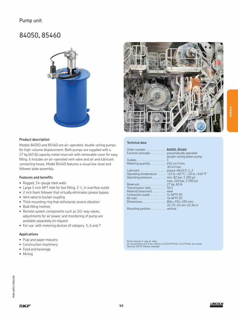
99
PU
B L
S/P
1 1
7046 E
N
Grea
se
Product description
Models 84050 and 85460 are air-operated, double-acting pumps
for high-volume displacement. Both pumps are supplied with a
27 kg (60 lb) capacity metal reservoir with removable cover for easy
filling. It includes an air-operated vent valve and air and lubricant
connecting hoses. Model 85460 features a visual low-level and
follower plate assembly.
Features and benefits
• Rugged, 14-gauge steel walls
• Large 1 inch NPT inlet for fast filling, 1 1/4 in overflow outlet
• 2 inch foam follower that virtually eliminates grease bypass
• Vent valve to bucket coupling
• Thick mounting ring that withstands severe vibration
• Bulk filling method
• Remote system components such as 3/2-way valves,
adjustments for air power, and monitoring of pump are
available separately on request
• For use with metering devices of category 5, 6 and 7
Applications
• Pulp and paper industry
• Construction machinery
• Food and beverage
• Mining
Pump unit
84050, 85460
Technical data
Order number . . . . . . . . . . . . 84050, 85460Function principle . . . . . . . . . pneumatically operated
double-acting piston pumpOutlets. . . . . . . . . . . . . . . . . . 1Metering quantity . . . . . . . . . 492 cm 3/ min
30 in3/ minLubricant. . . . . . . . . . . . . . . . grease xNLGI 0, 1, 2Operating temperature . . . . . –23 to +60 °C; –10 to +140 °FOperating pressure . . . . . . . . min. 82 bar, 1 200 psi
max. 240 bar, 3 500 psiReservoir. . . . . . . . . . . . . . . . 27 kg, 60 lbTransmission ratio . . . . . . . . . 50:1Material (reservoir) . . . . . . . . steelConnection outlet . . . . . . . . . 3/4 NPTF (F)Air inlet . . . . . . . . . . . . . . . . . 3/8 NPTF (F)Dimensions . . . . . . . . . . . . . . 806 × 392 × 395 mm
31.75 × 15.44 × 15.56 inMounting position . . . . . . . . . vertical
Pump requires 3-way air valveAir consumption at 6,9 bar, 100 psi, is 0,012 M 3/min, 0.42 ft3/min, per strokeOptional 92597 follower available

100
PU
B L
S/P
1 1
7046 E
N
Gre
ase
Product description
All models are air-operated, positive-displacement pumps
delivering a maximum volume by means of a single stroke of
the pump. Solenoid air valves and adjustable, solid-state time con-
trols are integrated into the pump body. Designed to deliver grease
to single-line metering devices, these pump models include a special
high-volume refill fitting. Integrated controls feature LED indicators
for “Power On”, “Pump On” and “Alarm,” along with a membrane-
type, “Manual Lube” switch. Model 1823 includes a 2 1/2 inch pneu-
matically driven pump, vent valve assembly, pump elevator, air and
lubricant connecting hoses and control panel. Model 282288 has
the same specifications as Model 1823 but does not include an
elevator or controller.
Features and benefits
• Modular structure consists of 2 1/2 in air motor, pump and vent
assembly, controller, pump elevator, air and lubricant connecting
hoses, as well as an optional control panel
• For U. S. standard refinery drums (removable head)
• For clean and safe drum replacement
• Simplified, modular design
• For use with metering devices of category 5, 6 and 7.
Applications
• Agriculture
• Chemical industry
• Steel industry
Technical data
Order number . . . . . . . . . . . . . . 282288Function principle . . . . . . . . . . . pneumatically operated
reciprocating piston pumpOutlets. . . . . . . . . . . . . . . . . . . . 1Metering quantity . . . . . . . . . . . 492 cm 3/ min, 30 in3/ minLubricant. . . . . . . . . . . . . . . . . . grease NLGI 0, 1, 2Operating temperature . . . . . . . –15 to +121 °C; +5 to 250 °FOperating pressure . . . . . . . . . . min. 82 bar, 1 200 psi
max. 240 bar, 3 500 psiTransmission ratio . . . . . . . . . . . 50:1Reservoir. . . . . . . . . . . . . . . . . . 55 kg, 120 lbDrum size . . . . . . . . . . . . . . . . . standard 120 lb. refinery drumMaterial . . . . . . . . . . . . . . . . . . . nitrile, steel, polyurethaneConnection outlet . . . . . . . . . . . 3/4 NPTF (F)Air inlet . . . . . . . . . . . . . . . . . . . 3/8 NPTF (F)Voltage (controller) . . . . . . . . . . 120 V, 60 Hz; 110 V, 50 HzDimensions . . . . . . . . . . . . . . . . 381 × 381 × 975 mm;
15 × 15 × 38.375 inMounting position . . . . . . . . . . . vertical
Pump unit
282288
Air consumption at 6,9 bar, 100 psi, is 0,004 M 3/min, 0.15 ft3/min, per stroke83371 follower plate is available as an optional accessory

101
PU
B L
S/P
1 1
7046 E
N
Grea
se
Product description
The hydraulic lubricator HG is an lubrication system developed for
a cost-efficient automatic lubrication in machines and implements
having a hydraulic circuit. With the help of the hydraulic lubricator,
centralized automatic lubrication can be adapted to such units as
dismountable hoists, small lift trucks and rear lifts of vehicles.
Features and benefits
• Simple piston pump utilizes self-relieving hydraulic lines
• Provides cost-efficient automatic lubrication
• Suitable for use in vehicles or machines having a safe
hydraulic circuit that is not constantly in operation
• Pressure rise and fall operation in the pump is activated by
powering-on and powering-off the adapted hydraulic circuit
• Pressure rise and fall operation in the lube line, as well
as the amount of lube remaining, can be verified from
the pressure gauge of the pump unit
• Optional low-level limit alarm can be indicated by
a buzzer or indicator lamp 12 or 24 V DC
• Filling coupler with filter
• For use with metering devices of category 4 and 5
Applications
• Vehicles
• Machines
• Dismountable hoists
• Small lift trucks
• Rear lifts of trucks
Technical data
Order number . . . . . . . . . . . . . . HG 1000HG 2000
Function principle . . . . . . . . . . . hydraulically operated piston pump
Outlets. . . . . . . . . . . . . . . . . . . . 1Metering quantity . . . . . . . . . . . depending on the inlet pressureLubricant. . . . . . . . . . . . . . . . . . grease NLGI 0, 1Operating temperature . . . . . . . -25 to +80 °C
-13 to +176 °FOperating pressure . . . . . . . . . . min. 50 bar; 725 psi
max. 150 bar; 2 176 psiReservoir. . . . . . . . . . . . . . . . . . 1 and 2 kg; 2.2 and 4.4 lbMaterial (reservoir) . . . . . . . . . . steelHydraulic inlet connection . . . . . R 1/4 in ZN;
main hose ø 8 mm, 0.341 inGrease outlet connection . . . . . . R 1/4 in ZN;
main hose ø 8 mm, 0.341 inTransmission ratio . . . . . . . . . . . 1:1 Operating voltage . . . . . . . . . . . 12 or 24 V DCDimensions . . . . . . . . . . . . . . . . HG 1000; 345 × 100 × 100 mm
13.58 × 3.94 × 3.94 in HG 2000; 520 × 100 × 100 mm 20.47 × 3.94 × 3.94 in
Mounting position . . . . . . . . . . . vertical or horizontal
Pump unit
HG 1000, HG 2000
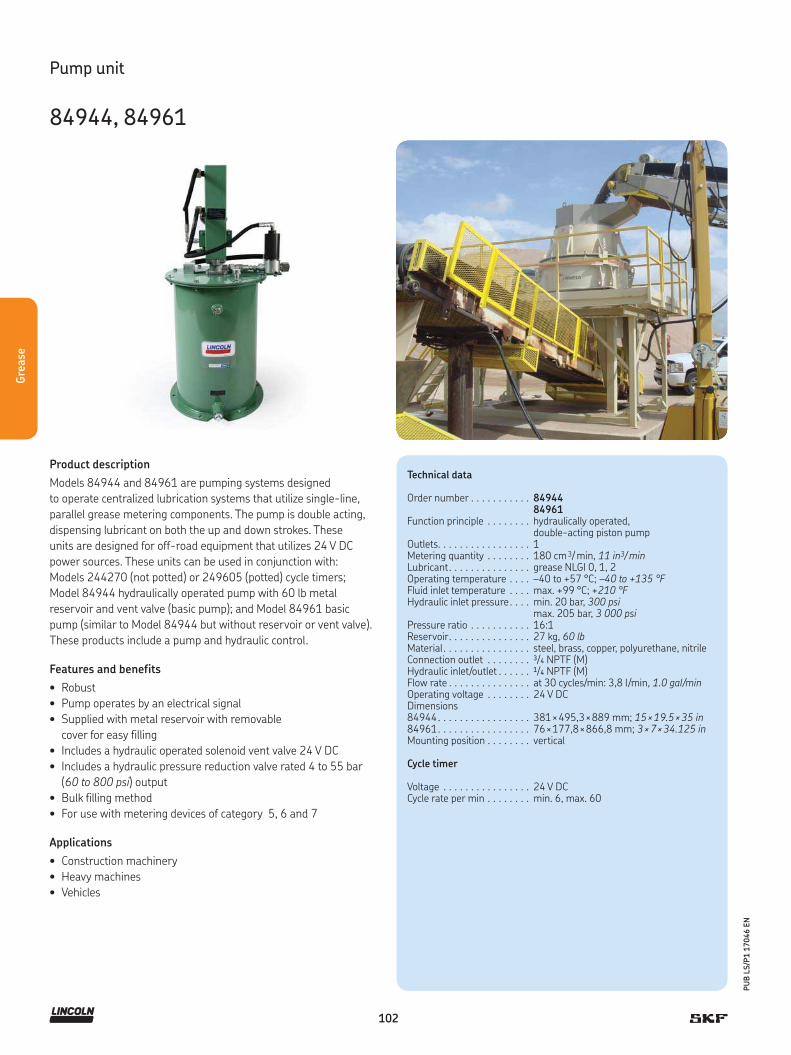
102
PU
B L
S/P
1 1
7046 E
N
Gre
ase
Product description
Models 84944 and 84961 are pumping systems designed
to operate centralized lubrication systems that utilize single-line,
parallel grease metering components. The pump is double acting,
dispensing lubricant on both the up and down strokes. These
units are designed for off-road equipment that utilizes 24 V DC
power sources. These units can be used in conjunction with:
Models 244270 (not potted) or 249605 (potted) cycle timers;
Model 84944 hydraulically operated pump with 60 lb metal
reservoir and vent valve (basic pump); and Model 84961 basic
pump (similar to Model 84944 but without reservoir or vent valve).
These products include a pump and hydraulic control.
Features and benefits
• Robust
• Pump operates by an electrical signal
• Supplied with metal reservoir with removable
cover for easy filling
• Includes a hydraulic operated solenoid vent valve 24 V DC
• Includes a hydraulic pressure reduction valve rated 4 to 55 bar
(60 to 800 psi) output
• Bulk filling method
• For use with metering devices of category 5, 6 and 7
Applications
• Construction machinery
• Heavy machines
• Vehicles
Technical data
Order number . . . . . . . . . . . 8494484961
Function principle . . . . . . . . hydraulically operated, double-acting piston pump
Outlets. . . . . . . . . . . . . . . . . 1Metering quantity . . . . . . . . 180 cm 3/ min, 11 in3/ minLubricant. . . . . . . . . . . . . . . grease NLGI 0, 1, 2Operating temperature . . . . –40 to +57 °C; –40 to +135 °FFluid inlet temperature . . . . max. +99 °C; +210 °FHydraulic inlet pressure. . . . min. 20 bar, 300 psi
max. 205 bar, 3 000 psiPressure ratio . . . . . . . . . . . 16:1Reservoir. . . . . . . . . . . . . . . 27 kg, 60 lbMaterial . . . . . . . . . . . . . . . . steel, brass, copper, polyurethane, nitrileConnection outlet . . . . . . . . 3/4 NPTF (M)Hydraulic inlet/outlet . . . . . . 1/4 NPTF (M)Flow rate . . . . . . . . . . . . . . . at 30 cycles/min: 3,8 l/min, 1.0 gal/minOperating voltage . . . . . . . . 24 V DCDimensions84944. . . . . . . . . . . . . . . . . 381 × 495,3 × 889 mm; 15 × 19.5 × 35 in84961. . . . . . . . . . . . . . . . . 76 × 177,8 × 866,8 mm; 3 × 7 × 34.125 inMounting position . . . . . . . . vertical
Cycle timer
Voltage . . . . . . . . . . . . . . . . 24 V DCCycle rate per min . . . . . . . . min. 6, max. 60
Pump unit
84944, 84961

103
PU
B L
S/P
1 1
7046 E
N
Grea
se
Product description
Models 84960 and 84962 are pumps designed to operate central-
ized lubrication systems that utilize single-line parallel grease me-
tering components. The pumps are double acting, dispensing lubri-
cant on both the up and down strokes. These units are designed for
off-road equipment that utilizes 24 V DC power sources. These units
can be used in conjunction with Models 244270 (not potted) or
249605 (potted) cycle timers. Included hydraulic solenoids require
24 V DC. Model 84960 is a hydraulic pump for use with U.S. stand-
ard 120 lb refinery drums. System components (pump, vent assem-
bly, drum cover and follower plate) must be ordered separately.
Model 84962 is a hydraulic pump for custom lubricant container
installations. Pump length is sized for U.S. standard 400 lb
refinery drum depth.
Features and benefits
• For use with U.S. standard 54 kg/120 lb refinery drum
• Robust
• Includes a hydraulic pressure reduction valve rated
4 to 55 bar (60 to 800 psi) output
• System components (pump, vent valve assembly,
drum cover and follower plate) must be ordered separately
• For use with metering devices of category 5, 6 and 7
Applications
• Mining industry
• Cement industry
Technical data
Order number . . . . . . . . . . . 8496084962
Function principle . . . . . . . . hydraulically operated double-acting piston pump
Outlets. . . . . . . . . . . . . . . . . 1Metering quantity . . . . . . . . 180 cm 3/ min, 11 in3/ minLubricant. . . . . . . . . . . . . . . grease NLGI 0, 1, 2Operating temperature . . . . –40 to +57 °C; –40 to +135 °FFluid inlet temperature . . . . max. +99 °C; +210 °FHydraulic inlet pressure. . . . min. 20 bar, 300 psi
max. 205 bar, 3 000 psiPressure ratio . . . . . . . . . . . 16:1Material . . . . . . . . . . . . . . . . steel, brass, copper, polyurethane, nitrileConnection outlet . . . . . . . . 3/4 NPTF (F)Hydraulic inlet/outlet . . . . . . 1/4 NPTF (M)Flow rate . . . . . . . . . . . . . . . at 30 cycles/min: 3,8 l/min, 1.0 gal/minDimensions84960. . . . . . . . . . . . . . . . . 76 × 177,8 × 1 083 mm; 3 × 7 × 42.625 in84962. . . . . . . . . . . . . . . . . 76 × 177,8 × 862 mm; 3 × 7 × 33.94 inMounting position . . . . . . . . vertical
Cycle timer
Voltage . . . . . . . . . . . . . . . . 24 V DCCycle rate per min . . . . . . . . min. 6, max. 60
Pump unit
84960, 84962
Pumps require a timed electrical signal to operate. Use 244270 (not potted) or 249605 (potted)cycle timer. Included hydraulic solenoids require 24 V DC. All pumps have a hydraulic pressure-
reducing valve rated for 4 to 55 bar, 60 to 800 psi, output. Maximum input is 207 bar, 3 000 psi.

104
PU
B L
S/P
1 1
7046 E
N
Gre
ase
Product description
High-performance FlowMaster hydraulic pumps combine
rotary-driven pump motors with reciprocating pump tubes and
flexible control features that perform in desert heat and arctic cold.
The integrated control manifold adjusts the amount of lubricant and
operating pressure. The pump’s output is adjustable from 115 to
737 cm³/min (7 to 45 in³/min).
Features and benefits
• Increases pump life and simplifies pump installation,
operation and service
• Pump and reservoir combination models are
automatically level-sensor and shut-off system ready
• Premium-choice pump for single-line parallel lubrication systems
• Flexible ranges of use pump only or pump
and bucket with follower low- and high-level detection
• For desert heat and cold climates
• For use with metering devices of category 5, 6 and 7
Applications
• Construction machinery, mining and mineral processing
• Steel mills, paper mills, automotive
• Food and beverage, packaging
Technical data
Function principle . . . . . . . . . . . hydraulically operated piston pumpOutlets. . . . . . . . . . . . . . . . . . . . 1Metering quantity . . . . . . . . . . . adjustable
115 to 737 cm 3/ min 7 to 45 in3/ min
Lubricant. . . . . . . . . . . . . . . . . . grease NLGI 0, 1, 2Hydraulic fluid temperature. . . . max. +93 °C; +200 °FOperating temperature . . . . . . . –29 to +65 °C; –20 to +150 °FOperating inlet pressure . . . . . . 20 to 32 bar, 300 to 420 psiSupply inlet pressure . . . . . . . . . max. 200 bar, 3 000 psiReservoir. . . . . . . . . . . . . . . . . . 16; 27; 41; 54; 180 kg
35; 60; 90; 120; 400 lbMaterial . . . . . . . . . . . . . . . . . . . fluoroelastomer, polyurethane,
steel, aluminum zinc castingConnection outlet . . . . . . . . . . . 1/4 NPTFHydraulic inlet flow . . . . . . . . . . max. 28 l/min, 7 gal/minSolenoid valve coil . . . . . . . . . . . 24 V DCHydraulic inlet port . . . . . . . . . . SAE 4Tank return port . . . . . . . . . . . . SAE 6Transmission ratio with manifold . . . . . . . . . . . . . . 9:1 at low inlet pressure (20 to 25 bar,
300 to 350 psi) and flow (below 7 lpm, 2 gpm); approaches 11:1 at higher inlet pressure and flow
Dimensions:Pump, dip tube length . . . . . . . . min. 348 mm; 13.7 in
max. 864 mm; 34.02 inBasic pump . . . . . . . . . . . . . . . . min. 610 × 231 × 291 mm
min. 24 × 9 × 11.5 inmax. 1 126 × 231 × 291 mm max. 44.3 × 9 × 11.5 in
Pumps with bucket, follower and vent valve . . . . . . . . . . . . . . min. 633 × 496mm
min. 24.9 × 19.5 in max. 1 155 × 496 mm max. 45.44 × 19.5 in
Mounting position . . . . . . . . . . . vertical
Pump unit
FlowMaster, hydraulic

105
PU
B L
S/P
1 1
7046 E
N
Grea
se
Pump unit
FlowMaster, hydraulic
Order number
Order number Designation Reservoir Solenoid manual override
Adjustable flow control
Adjustable pressure control
kg lb
85722 pump and bucket with follower and low-level detection 27 60 – • •85723 reservoir and pump 27 60 – – –85724 reservoir and pump 27 60 – – –85725 pump and bucket with follower and low-level detection 41 90 – • •85726 pump and bucket 41 90 • – –85727 pump and bucket with follower, low- and high-level detection 54 120 – • •
85731 pump only 16 35 – • •85732 pump only 27 60 – • •85733 pump only 54/41 120/90 – • •85734 pump only 180 400 – • •85735 pump only 27 60 – – –85741 pump only 27 60 • – –85742 pump only 54/41 120/90 • – –
Order number
Order number Designation Reservoir
gal lb
84616 drum cover 18 12085492 follower assembly 18 12084990 vent valve assembly 18 120
271606 drum cover 55 400270982 follower assembly 55 400271605 vent valve assembly 55 400
84980 vent valve 18, 55 120, 400
237-11204-8 ultrasonic high/low sensor 18, 55 120, 400
Accessory
Drum covers, follower assemblies and vent valve assemblies

106
PU
B L
S/P
1 1
7046 E
N
Gre
ase
Product description
The simple-to-install, all-in-one design of the P 603S pump in-
cludes the programmable controller, a pressure switch/transducer
and a vent valve. It is quick and easy to change out a metering device
as the main line or nearby metering devices do not have to be re-
moved. The exchange can be performed between lubrication cycles
so that there is no wasted lubricant or excessive costly downtime. An
additional pressure switch at the end of larger systems can be used
for added pressure control to ensure correct lubrication. For rotating
operation in wind turbines, the reservoir is equipped with a follower
plate and stirring paddle, which also facilitates the use of fast-sepa-
rating lubricants. For stationary operations, a stirring and fixed pad-
dle is sufficient.
Features and benefits
• Robust design with easy system layout
• Simple maintenance
• Easy system expandation
• SE1/SE2 suction elements for used lubricant
• QSL / SL metering devices suitable for high pressure
• Suitable for fast-separating lubricants
• For use with metering devices of category 5, 6, 7
Applications
• Wind turbines
• Construction machinery
• Mining and mineral processing
• Commercial vehicles
Technical data
Function principle . . . . . . . electrically operated piston pump
Outlets. . . . . . . . . . . . . . . . 1Metering quantity . . . . . . . 12 cm 3/ min, 0.73 in3/ minLubricant. . . . . . . . . . . . . . grease up to NLGI 2Operating temperature . . . –40 to +70 °C; –40 to +158 °FOperating pressure . . . . . . max. 300 bar; 4 350 psiReservoir. . . . . . . . . . . . . . 4; 8; 10; 15 or 20 kg
9, 18, 22, 33 or 44 lbPumping elements . . . . . . 3 (ø 7 mm, 0.27 in)Paddle . . . . . . . . . . . . . . . . 18 rpmOperating voltage . . . . . . . 24 V DC, 115 V AC, 230 V ACCurrent draw . . . . . . . . . . . max. 2 AProtection class . . . . . . . . . IP 6K9KConnectors . . . . . . . . . . . . 12, 24 V DC: bayonet style
AC: bayonet style plus square typeSwitching power supply. . . 12, 24 V DC: no AC: yesMaterial . . . . . . . . . . . . . . . cast aluminum alloy,
polycarbonate resinConnection outlet . . . . . . . G1/4
Dimensions . . . . . . . . . . . . min. 471 × 240 × 235 mmmax. 949 × 240 × 235 mmmin. 18.54 × 9,44 × 9,25 inmax. 37.08 × 9,44 × 9,25 in
Mounting position . . . . . . . vertical (with follower plate; any)
Pump unit
P 603S

107
PU
B L
S/P
1 1
7046 E
N
Grea
se
Pump unit
P 603S
Order number
Order number Designation Power Reservoir capacity
Follower plate
Internal transducer
kg lb
645-41064-3 P603S-4XLF -3Z7-AC-2A7.16-S13-SE AC 4 9 • •645-41062-3 P603S-8XLF -3Z7-AC-2A7.16-S13-SE AC 8 18 • •645-41110-2 P603S-8XLBO-3Z7-AC-3A7.16-S12-SE AC 8 18 – •645-41062-4 P603S-8XLBO-3Z7-AC-3A7.16-S19-SE AC 8 18 – •645-41073-5 P603S-15XLF -3Z7-AC-2A7.16-S13-SE AC 15 33 • •
645-41064-8 P603S-4XLF1-3Z7-12-1A7.16-S01-SE 12 DC 4 9 • (bayonet) •645-41064-7 P603S-4XNBO-3Z7-12-2A7.16-S01-SE 12 DC 4 9 – •645-41110-3 P603S-8XLF1-3Z7-12-1A7.16-S01-SE 12 DC 8 18 • (bayonet) •645-41062-9 P603S-8XLF -3Z7-24-1A7.16-S01-SE 24 DC 8 18 • •645-41064-4 P603S-4XLBO-3Z7-24-1A7.16-S17-SE 24 DC 4 9 – •
645-41064-6 P603S-4XLF -3Z7-24-1A7.16-S13-SE 24 DC 4 9 • •645-41064-2 P603S-4XNBO-3Z7-24-1A7.16-S01-SE 24 DC 4 9 – •645-41062-8 P603S-8XLBO-3Z7-24-2A7.16-S19-SE 24 DC 8 18 – •645-41062-9 P603S-8XLF -3Z7-24-1A7.16-S01-SE 24 DC 8 18 • •645-41062-7 P603S-8XLF -3Z7-24-1A7.16-S03-SE 24 DC 8 18 • •
645-41119-1 P603S-10XLF -3Z7-24-1A7.16-S13-SE 24 DC 10 22 • •645-41175-5 P603S-4XNBO -3Z7-12-1A7.16-S22-SE 12 DC 4 9 – •645-41119-2 P603S-10XLF -3Z7-AC-2A1.01-S13-SE AC 10 22 • •
Accessory
P653S and P603S reservoir kits
Reservoir kits
Order number Reservoir size Designation
kg lb
276764 15 33 Converts 4 or 8 kg, 9 or 18 lb, reservoirs without follower to 15 kg, 33 lb reservoir276765 20 44 Converts 4 or 8 kg, 9 or 18 lb, reservoirs without follower to 20 kg, 44 lb reservoir
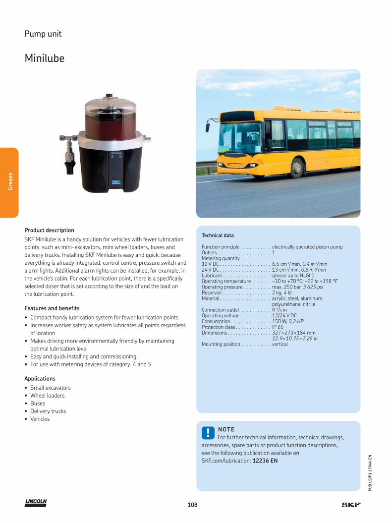
108
PU
B L
S/P
1 1
7046 E
N
Gre
ase
Product description
SKF Minilube is a handy solution for vehicles with fewer lubrication
points, such as mini-excavators, mini wheel loaders, buses and
delivery trucks. Installing SKF Minilube is easy and quick, because
everything is already integrated: control centre, pressure switch and
alarm lights. Additional alarm lights can be installed, for example, in
the vehicle’s cabin. For each lubrication point, there is a specifically
selected doser that is set according to the size of and the load on
the lubrication point.
Features and benefits
• Compact handy lubrication system for fewer lubrication points
• Increases worker safety as system lubricates all points regardless
of location
• Makes driving more environmentally friendly by maintaining
optimal lubrication level
• Easy and quick installing and commissioning
• For use with metering devices of category 4 and 5
Applications
• Small excavators
• Wheel loaders
• Buses
• Delivery trucks
• Vehicles
!NOTE
For further technical information, technical drawings,
accessories, spare parts or product function descriptions,
see the following publication available on
SKF.com/lubrication: 12236 EN
Technical data
Function principle . . . . . . . . . . . electrically operated piston pumpOutlets. . . . . . . . . . . . . . . . . . . . 1Metering quantity12 V DC . . . . . . . . . . . . . . . . . . . 6,5 cm³/ min, 0.4 in³/ min24 V DC . . . . . . . . . . . . . . . . . . . 13 cm³/ min, 0.8 in³/ minLubricant. . . . . . . . . . . . . . . . . . grease up to NLGI 1Operating temperature . . . . . . . –30 to +70 °C; –22 to +158 °FOperating pressure . . . . . . . . . . max. 250 bar, 3 625 psiReservoir. . . . . . . . . . . . . . . . . . 2 kg, 4 lbMaterial . . . . . . . . . . . . . . . . . . . acrylic, steel, aluminum,
polyurethane, nitrile Connection outlet . . . . . . . . . . . R 1/4 inOperating voltage . . . . . . . . . . . 12/24 V DCConsumption. . . . . . . . . . . . . . . 150 W, 0.2 HPProtection class . . . . . . . . . . . . . IP 65Dimensions . . . . . . . . . . . . . . . . 327 × 273 × 184 mm
12.9 × 10.75 × 7.25 inMounting position . . . . . . . . . . . vertical
Pump unit
Minilube
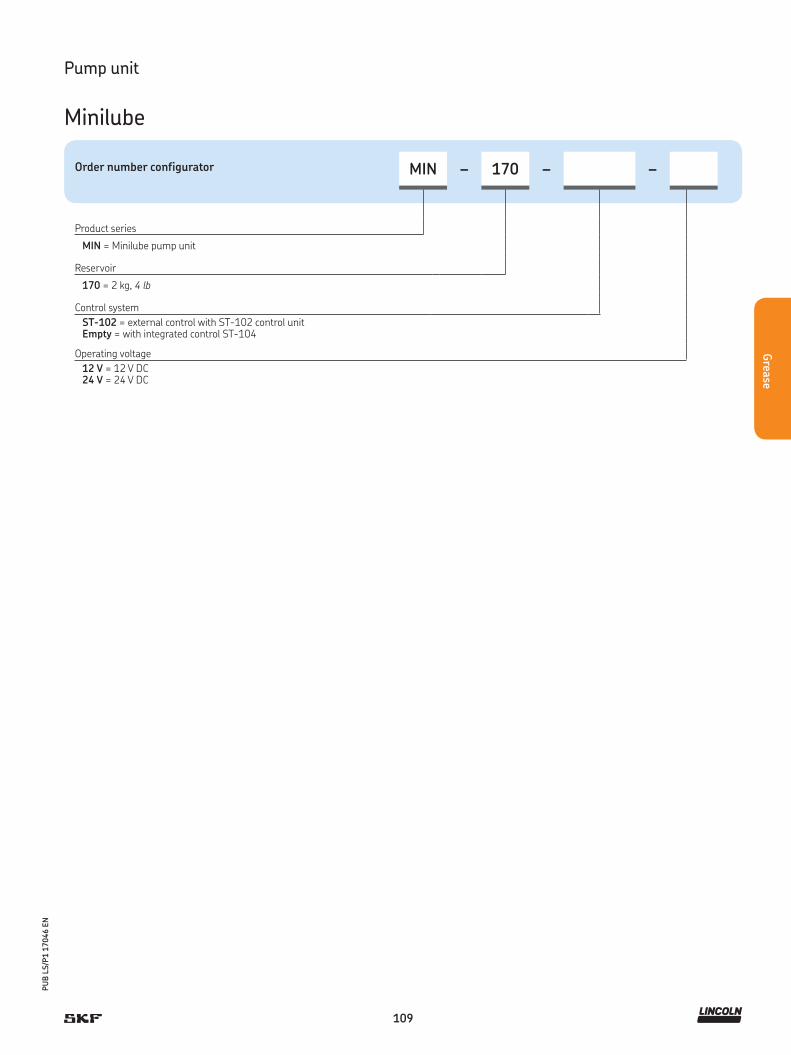
109
PU
B L
S/P
1 1
7046 E
N
Grea
se
Order number configurator MIN – 170 – –
Product series
MIN = Minilube pump unit
Reservoir
170 = 2 kg, 4 lb
Control system
ST-102 = external control with ST-102 control unitEmpty = with integrated control ST-104
Operating voltage
12 V = 12 V DC24 V = 24 V DC
Pump unit
Minilube

110
PU
B L
S/P
1 1
7046 E
N
Gre
ase
Product description
The KFG pump unit is an electrically driven piston pump.
The pump is comprised of four main components: housing with
pump elements; reservoir with fill-level monitoring; internal control
units; and attachments. The housing integrates the motor, the drive
shaft with an eccentric and up to three pump elements for delivering
the lubricant. Positively driven pump elements should be used in or-
der to maintain the delivery rate in areas with extremely low tem-
peratures or in applications where an increased influence of dirt
is unavoidable.
Features and benefits
• Reliable: due to durable materials, robust
components and designs for extreme conditions
(with positively driven pump elements)
• Plug-and-play pump design for reduced installation time
• Application-oriented: individual designs through
user-friendly product customizer
• Versatile: can be used as a single-line (SKF MonoFlex)
and as a progressive pump (SKF ProFlex)
• Safe: through fill-level monitoring, lubrication
system monitoring, pressure relief and control unit
• Options: Top filling, several electronic options, Can bus
• For use with metering devices of category 5, 6 and 7
Applications
• Wind turbines
• Construction machinery
• Vehicle aftermarket
• Rotary applications
• Industry
!NOTE
For further technical information, technical drawings,
accessories, spare parts or product function descriptions,
see the following publication available on
SKF.com/lubrication: 1-3030 -EN, 951-170-211
3D data and product configuration:
skf-lubrication.partcommunity.com/3d-cad-models/
Technical data
Function principle . . . . . . . . . . . . electrically operated piston pumpOutlets. . . . . . . . . . . . . . . . . . . . . 1-3Metering quantity . . . . . . . . . . . . 5,0 to 15 cm³/ min
0.3 to 0.9 in3/minLubricant. . . . . . . . . . . . . . . . . . . NLGI 000 to 2 with EP additives,
compatible with plastics, NBR elastomers, copper and copper alloys
Operating temperature:with spring-return pump element
–25 to +70 °C; –13 to +158 °F
with posit. driven pump element –30 to +70 °C; –22 to +158 °FOperating pressure . . . . . . . . . . . max. 300 bar; 4 351psiFlow pressure . . . . . . . . . . . . . . . 0,45 to 0,7 bar, 6.5 to 10.2 psiReservoir. . . . . . . . . . . . . . . . . . . 2; 4; 6; 8; 10; 12; 15; 20 kg
4, 9, 13, 18, 22, 26, 33, 44 lbMaterial (reservoir) . . . . . . . . . . . polyamide PA 6I, PMMAMaterial (pump housing) . . . . . . . aluminum-silicon cast alloyConnection outlet . . . . . . . . . . . . M 14×1,5 mmOperating voltage . . . . . . . . . . . . 12 V DC, 24 V DC, 230 V AC
(90–264 V AC)Dimensions . . . . . . . . . . . . . . . . . min 229 × 268 × 208mm
min 9.01 × 10.55 × 8.2 inmax 1 170 × 268 × 216 mm max 46 × 10.55 × 8.5 in
Mounting position . . . . . . . . . . . . vertical (with follower plate; any)
Pump unit
KFG
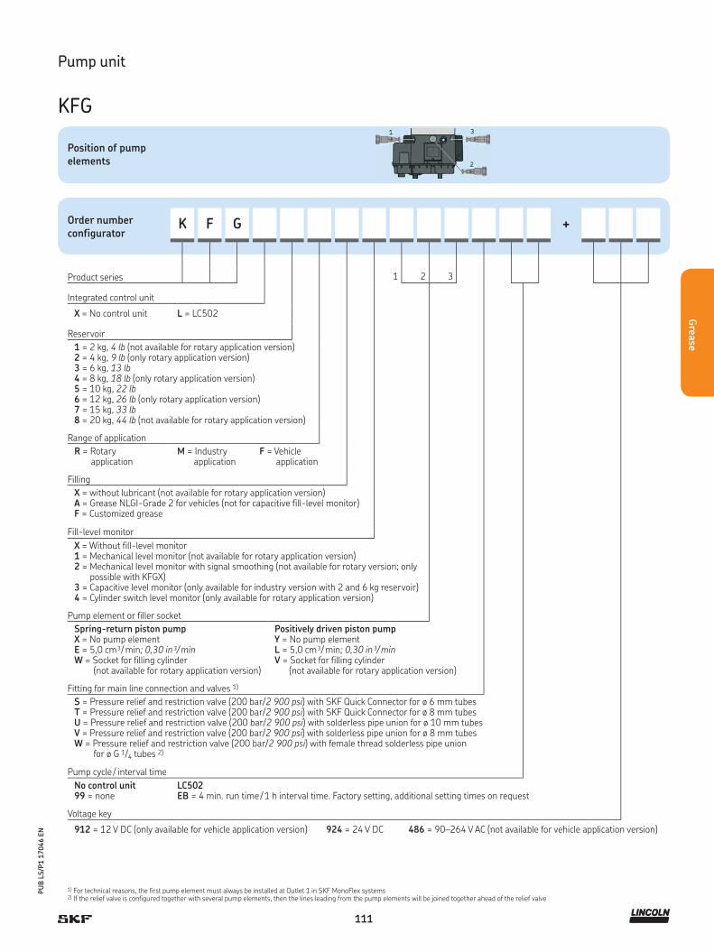
111
PU
B L
S/P
1 1
7046 E
N
Grea
se
Pump unit
KFG
Order numberconfigurator
K F G +
1 2 3Product series
Integrated control unit
X = No control unit L = LC502
Reservoir
1 = 2 kg, 4 lb (not available for rotary application version)2 = 4 kg, 9 lb (only rotary application version)3 = 6 kg, 13 lb4 = 8 kg, 18 lb (only rotary application version)5 = 10 kg, 22 lb6 = 12 kg, 26 lb (only rotary application version)7 = 15 kg, 33 lb8 = 20 kg, 44 lb (not available for rotary application version)
Range of application
R = Rotary application
M = Industry application
F = Vehicle application
Filling
X = without lubricant (not available for rotary application version)A = Grease NLGI-Grade 2 for vehicles (not for capacitive fill-level monitor)F = Customized grease
Fill-level monitor
X = Without fill-level monitor1 = Mechanical level monitor (not available for rotary application version)2 = Mechanical level monitor with signal smoothing (not available for rotary version; only possible with KFGX)3 = Capacitive level monitor (only available for industry version with 2 and 6 kg reservoir) 4 = Cylinder switch level monitor (only available for rotary application version)
Pump element or filler socket
Spring-return piston pumpX = No pump element E = 5,0 cm³/ min; 0,30 in³/ minW = Socket for filling cylinder (not available for rotary application version)
Positively driven piston pumpY = No pump elementL = 5,0 cm³/ min; 0,30 in³/ minV = Socket for filling cylinder (not available for rotary application version)
Fitting for main line connection and valves 1)
S = Pressure relief and restriction valve (200 bar/2 900 psi) with SKF Quick Connector for ø 6 mm tubesT = Pressure relief and restriction valve (200 bar/2 900 psi) with SKF Quick Connector for ø 8 mm tubesU = Pressure relief and restriction valve (200 bar/2 900 psi) with solderless pipe union for ø 10 mm tubesV = Pressure relief and restriction valve (200 bar/2 900 psi) with solderless pipe union for ø 8 mm tubesW = Pressure relief and restriction valve (200 bar/2 900 psi) with female thread solderless pipe union for ø G 1/4 tubes 2)
Pump cycle / interval time
No control unit99 = none
LC502EB = 4 min. run time / 1 h interval time. Factory setting, additional setting times on request
Voltage key
912 = 12 V DC (only available for vehicle application version) 924 = 24 V DC 486 = 90–264 V AC (not available for vehicle application version)
Position of pump elements
1) For technical reasons, the first pump element must always be installed at Outlet 1 in SKF MonoFlex systems2) If the relief valve is configured together with several pump elements, then the lines leading from the pump elements will be joined together ahead of the relief valve

112
PU
B L
S/P
1 1
7046 E
N
Gre
ase
Product description
Multilube pump units help to ensure that the lubrication result is
optimal, while reducing energy and lubricant consumption. All rel-
evant components (control unit, pump, reservoir, directional valve
and pressure monitoring) are integrated into its modular pumping
unit. Built-in heating allows it to be operated even under
demanding and cold circumstances.
Features and benefits
• Compact, all-in-one structure
• Modular and durable design
• Easy to install and start-up
• Can be used in single-line, dual-line and
progressive lubrication systems
• For use in oil and grease lubrication systems
• Two reservoir sizes
• Pumping element equipped with pressure-relief valve
• Filling connection equipped with safety valve
• Visual and electric low-level monitoring in reservoir
• Pumping center is equipped with heating resistor
• Clear and versatile user interface
• Wide operating temperature range
• For use with metering devices of category 5, 6 and 7
Applications
• Stand-alone machines
• Construction machinery
• Mining applications!
NOTE
For further technical information, technical drawings,
accessories, spare parts or product function descriptions,
see the following publication available on
SKF.com/lubrication: 6407/2 EN
Technical data
Function principle . . . . . . . . . . . electrically operated piston pump
Outlets. . . . . . . . . . . . . . . . . . . . 1Metering quantity . . . . . . . . . . . 16 cm³/ min; 0.976 in³/ minLubricant. . . . . . . . . . . . . . . . . . grease up to NLGI 1Operating temperature . . . . . . . –30 to +80 °C; –22 to +176 °FOperating pressure . . . . . . . . . . max. 200 bar, 2 900 psiReservoir. . . . . . . . . . . . . . . . . . 4 or 10 kg,
9 or 22 lb Material . . . . . . . . . . . . . . . . . . . aluminum, polyurethane, nitrile Connection outlet . . . . . . . . . . . G 1/4Operating voltage . . . . . . . . . . . 12/24 V DC, 115 V AC, 230 V ACConsumption. . . . . . . . . . . . . . . 150 W, 0.2 HPProtection class . . . . . . . . . . . . . IP 67 (with user-interface IP 65)Dimensions:with 4 kg reservoir . . . . . . . . . . 539 × 274 × 250 mmwith 9 lb reservoir . . . . . . . . . . . 21.22 × 10.78 × 9.84 inwith 10 kg reservoir . . . . . . . . . 720 × 274 × 250 mmwith 22 lb reservoir . . . . . . . . . . 27.09 × 10.78 × 9.84 inMounting position . . . . . . . . . . . vertical
Pump unit
Multilube, MLP
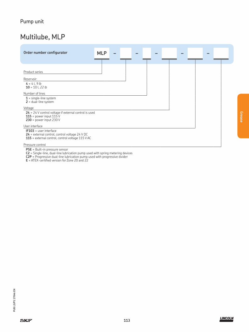
113
PU
B L
S/P
1 1
7046 E
N
Grea
se
Pump unit
Multilube, MLP
Order number configurator MLP – – – – –
Product series
Reservoir
4 = 4 l, 9 lb10 = 10 l, 22 lb
Number of lines
1 = single-line system2 = dual-line system
Voltage
24 = 24 V control voltage if external control is used115 = power input 115 V230 = power input 230 V
User interface
IF103 = user interface24 = external control, control voltage 24 V DC115 = external control, control voltage 115 V AC
Pressure control
PSE = Built-in pressure sensorC2 = Single-line, dual-line lubrication pump used with spring metering devicesC2P = Progressive dual-line lubrication pump used with progressive dividerE = ATEX-certified version for Zone 20 and 22
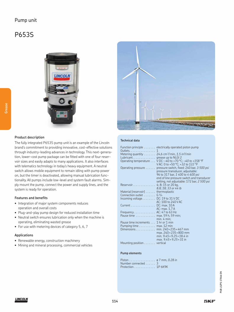
114
PU
B L
S/P
1 1
7046 E
N
Gre
ase
Product description
The fully integrated P653S pump unit is an example of the Lincoln
brand's commitment to providing innovative, cost-effective solutions
through industry-leading advances in technology. This next-genera-
tion, lower-cost pump package can be fitted with one of four reser-
voir sizes and easily adapts to many applications. It also interfaces
with telematics technology in today’s heavy equipment. A neutral
switch allows mobile equipment to remain idling with pump power
on, but the timer is deactivated, allowing manual lubrication func-
tionality. All pumps include low-level and system fault alarms. Sim-
ply mount the pump, connect the power and supply lines, and the
system is ready for operation.
Features and benefits
• Integration of major system components reduces
operation and overall costs
• Plug-and-play pump design for reduced installation time
• Neutral switch ensures lubrication only when the machine is
operating, eliminating wasted grease
• For use with metering devices of category 5, 6, 7
Applications
• Renewable energy, construction machinery
• Mining and mineral processing, commercial vehicles
Technical data
Function principle . . . . . . . electrically operated piston pumpOutlets. . . . . . . . . . . . . . . . 1Metering quantity . . . . . . . 24,6 cm 3/ min, 1.5 in3/ minLubricant. . . . . . . . . . . . . . grease up to NLGI 2Operating temperature . . . V DC: –40 to +70 °C; –40 to +158 °F
V AC: 0 to +50 °C; +32 to 122 °FOperating pressure . . . . . . pressure switch, fixed: 240 bar, 3 500 psi
pressure transducer, adjustable: 96 to 317 bar, 1 400 to 4 600 psiend of line pressure switch and transducer setting, not adjustable: 172 bar, 2 500 psi
Reservoir. . . . . . . . . . . . . . 4; 8; 15 or 20 kg, 8.8; 18; 33 or 44 lb
Material (reservoir) . . . . . . thermoplasticConnection outlet . . . . . . . G 1/4
Incoming voltage . . . . . . . . DC: 19 to 31 V DCAC: 100 to 240 V AC
Current . . . . . . . . . . . . . . . DC: max. 10 AAC: max. 1,7 A
Frequency . . . . . . . . . . . . . AC: 47 to 63 HzPause time . . . . . . . . . . . . max. 59 h, 59 min;
min. 4 min;Pause time increments . . . 1 hr or 1 minPumping time . . . . . . . . . . max. 12 minDimensions . . . . . . . . . . . . min. 240 × 235 × 467 mm
max. 240 × 235 × 800 mmmin. 9.45 × 9.25 × 18.4 inmax. 9.45 × 9.25 × 31 in
Mounting position . . . . . . . vertical
Pump elements
Piston . . . . . . . . . . . . . . . . ø 7 mm, 0.28 inNumber connected . . . . . . 3Protection . . . . . . . . . . . . . 1P 6K9K
Pump unit
P653S
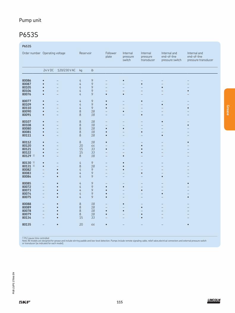
115
PU
B L
S/P
1 1
7046 E
N
Grea
se
Pump unit
P653S
P653S
Order number Operating voltage Reservoir Followerplate
Internal pressure switch
Internal pressure transducer
Internal and end-of-line pressure switch
Internal and end-of-line pressure transducer
24 V DC 120/230 V AC kg lb
80086 • – 4 9 – • – – –80087 • – 4 9 – – • – –80105 • – 4 9 – – – • –80106 • – 4 9 – – – – •80076 • – 4 9 • • – – –
80077 • – 4 9 • – • – –80109 • – 4 9 • – – • –80110 • – 4 9 • – – – •80090 • – 8 18 – • – – –80091 • – 8 18 – – • – –
80107 • – 8 18 – – – • –80108 • – 8 18 – – – – •80080 • – 8 18 • • – – –80081 • – 8 18 • – • – –80111 • – 8 18 • – – • –
80112 • – 8 18 • – – – •80120 • – 20 44 – – • – –80121 • – 15 33 • – • – –80122 • – 15 33 – – • – –80129 1) • – 8 18 – • – – –
80130 1) • – 4 9 – • – – –80131 1) • – 8 18 – • – – –80082 – • 4 9 – • – – –80083 – • 4 9 – – • – –80084 – • 4 9 – – – • –
80085 – • 4 9 – – – – •80072 – • 4 9 • • – – –80073 – • 4 9 • – • – –80074 – • 4 9 • – – • –80075 – • 4 9 • – – – •
80088 – • 8 18 – • – – –80089 – • 8 18 – – • – –80078 – • 8 18 • • – – –80079 – • 8 18 • – • – –80134 – • 15 33 – – • – –
80135 – • 20 44 • – – – •
1) PLC pause time controlledNote: All models are designed for grease and include stirring paddle and low-level detection. Pumps include remote signaling cable, relief valve,electrical connectors and external pressure switch or transducer (as indicated for each model).

116
PU
B L
S/P
1 1
7046 E
N
Gre
ase
Product description
The FK pump unit is a multi-function piston pump with a versatile,
modular structure. The FK pump unit can be used as a single-line,
dual-line or progressive pump unit with or without integrated re-
versing valves. The modular structure of the pump also allows it to
be retrofitted from one of the above-mentioned lubrication systems
to another system without much effort or expense. The pump, which
was designed to handle demanding usage, is available with reservoir
sizes of 15 kg (33 lb), 30 kg (66 lb) and 60 kg (132 lb).
Features and benefits
• Versatile, modular system; easy to retrofit to other systems
• High functional reliability due to positively driven pistons
• Fill-level monitoring (using ultrasonic sensor)
with two adjustable switching points
Applications
• Automotive industry
• Rotary applications
• Assembly lines
• Printing presses
!NOTE
For further technical information, technical drawings,
accessories, spare parts or product function descriptions,
see the following publication available on
SKF.com/lubrication: 1-3033-EN, 951-170-200-EN
Technical data
Function principle . . . . . . . . . . . . electrically operated piston pump
Outlets. . . . . . . . . . . . . . . . . . . . . 1Metering quantity . . . . . . . . . . . . 12,3 to 74 cm³/min
0.75 to 4.5 in³/minLubricant. . . . . . . . . . . . . . . . . . . mineral oils or environmentally
compatible oils from ISO VG 46 to greases of NLGI Class 2 (consultation required for synthetic oils)
Operating temperature . . . . . . . . -25 to +60 °C; -13 to 140 °FOperating pressure . . . . . . . . . . . max. 400 bar, 5 802 psiReservoir. . . . . . . . . . . . . . . . . . . 15; 30 or 60 kg,
33, 66 or 132 lbMaterial . . . . . . . . . . . . . . . . . . . . steel-sheet housing,
steel, aluminumOperating voltage . . . . . . . . . . . . 230/400 V ACPumping elements . . . . . . . . . . . 1 to 6Filling method . . . . . . . . . . . . . . . via filler socket G 1/2 inGear type. . . . . . . . . . . . . . . . . . . screw drive, type 1MGear ratio . . . . . . . . . . . . . . . . . . 40:1Nominal speed . . . . . . . . . . . . . . 1 500 rpmFrequency . . . . . . . . . . . . . . . . . . 50 HzNominal output . . . . . . . . . . . . . . 0,37 kWRated current . . . . . . . . . . . . . . . 1,09 AProtection . . . . . . . . . . . . . . . . . . IP 55-FConnection outlet . . . . . . . . . . . . G 1/2
Dimensions:15 kg (33 lb) . . . . . . . . . . . . . . . . max. 470 × 598 × 335 mm
max. 18.5 × 23.54 × 13.18 in30 kg (66 lb) . . . . . . . . . . . . . . . . max. 665 × 598 × 335 mm
max. 26.2 × 23.54 × 13.18 in60 kg (132 lb) . . . . . . . . . . . . . . . max. 1 035 × 598 × 335 mm
max. 40.74 × 23.54 × 13.18 inMounting position . . . . . . . . . . . . vertical
Pump unit
FK
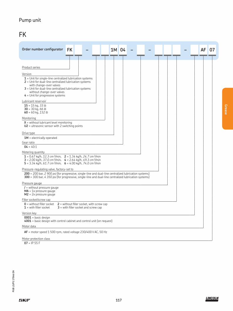
117
PU
B L
S/P
1 1
7046 E
N
Grea
se
Order number configurator FK – 1M 04 – – – AF 07
Product series
Version
1 = Unit for single-line centralized lubrication systems2 = Unit for dual-line centralized lubrication systems
with change-over valves3 = Unit for dual-line centralized lubrication systems
without change-over valves4 = Unit for progressive systems
Lubricant reservoir
15 = 15 kg, 33 lb30 = 30 kg, 66 lb60 = 60 kg, 132 lb
Monitoring
X = without lubricant level monitoringU2 = ultrasonic sensor with 2 switching points
Drive type
1M = electrically operated
Gear ratio
04 = 40:1
Metering quantity
1 = 0.67 kg/h, 12.3 cm 3/min. 2 = 1.34 kg/h, 24.7 cm 3/min3 = 2.00 kg/h, 37.0 cm 3/min. 4 = 2.64 kg/h, 49.3 cm 3/min5 = 3.34 kg/h, 61.7 cm 3/min. 6 = 4.00 kg/h, 74.0 cm 3/min
Pressure-regulating valve, factory-set to
200 = 200 bar, 2 900 psi (for progressive, single-line and dual-line centralized lubrication systems)300 = 300 bar, 4 350 psi (for progressive, single-line and dual-line centralized lubrication systems)
Pressure gauge
/ = without pressure gaugeMA = 1x pressure gaugeM2 = 2x pressure gauge
Filler socket/screw cap
0 = without filler socket 2 = without filler socket, with screw cap1 = with filler socket 3 = with filler socket and screw cap
Version key
0001 = basic design4001 = basic design with control cabinet and control unit (on request)
Motor data
AF = motor speed 1 500 rpm, rated voltage 230/400 V AC, 50 Hz
Motor protection class
07 = IP 55 F
Pump unit
FK

118
PU
B L
S/P
1 1
7046 E
N
Gre
ase
Product description
The high-performance FlowMaster product line is a new generation
of pump technology. Compact and versatile, its unique rotary drive
and modular gear set let you adjust the speed of the pump's motor
to exactly fit your application. FlowMaster pumps can save the cost
of air and plug in 12/24 V DC, 120/230-1ph and 230/460-3ph V AC
models. The motion of pump created by the electric rotary motor is
converted into reciprocating pump motion, providing an efficient
lubricant flow. Because of its rotary drive, the motor can be placed
directly on the pump. As a result, the pump is so compact it fits
almost anywhere.
Features and benefits
• Advanced technology: brushless DC motor
• Temperature and overload protection: durable and
long-lasting product that reduces machinery downtime
for maintenance; less repair costs
• Totally sealed: withstands washdowns
• For use with metering devices of category 5, 6 and 7
Applications
• Mining and mineral processing, construction machinery
• Steel mills, paper mills, food and beverage
!NOTE
For further technical information, technical drawings,
accessories, spare parts or product function descriptions,
see the following publication available on
SKF.com/lubrication: 12938-EN
Pump unit
FlowMaster, electric
Technical data
Function principle . . . . . . . . . electrically operated piston pumpOutlets. . . . . . . . . . . . . . . . . . 1Metering quantity . . . . . . . . . max. 103 cm³/min
max. 6.3 in³/minLubricant. . . . . . . . . . . . . . . . grease NLGI Grade 0, 1, 2Operating temperature . . . . . –40 to +65 °C; –40 to +150 °FOperating pressure:12 V DC . . . . . . . . . . . . . . . . . max. 251 bar; 3 500 psi24 V DC . . . . . . . . . . . . . . . . . max. 345 bar; 5 000 psi120 to 460 V AC . . . . . . . . . . max. 345 bar; 5 000 psiOperating voltage . . . . . . . . . 12/24 V DC; 120 to 460 V ACReservoir. . . . . . . . . . . . . . . . 40, 55, 180 kg; 90, 120, 400 lbMaterial . . . . . . . . . . . . . . . . . fluoroelastomer, polyurethane, steel,
aluminum zinc castingConnection outlet . . . . . . . . . 1/4 NPTFGear ratio . . . . . . . . . . . . . . . 17.8:1; 19:1; 34:1Nominal power . . . . . . . . . . . 5 to 50 and 9,5 to 100 rpmElectric current12/24 V DC . . . . . . . . . . . . . . 1 to 7.5 A120 V AC . . . . . . . . . . . . . . . . 1 to 4.6 A230-460 V AC . . . . . . . . . . . 0,5 to 2,4 A
Dimensions:16, 25, 28, 35, 40 kg . . . . . . 35, 55, 60, 78, 90 lb . . . . . . .
360 × 350 × 170 mm14.17 × 13.78 × 6.7 in
55 Kg . . . . . . . . . . . . . . . . . . 120 lb . . . . . . . . . . . . . . . . . .
408 × 223 × 946 mm 16.07 × 8.78 × 37.24 in
180 kg. . . . . . . . . . . . . . . . . . 400 lb . . . . . . . . . . . . . . . . . .
408 × 223 × 1 111 mm 16.07 × 8.78 × 43.24 in
Mounting position . . . . . . . . . vertical
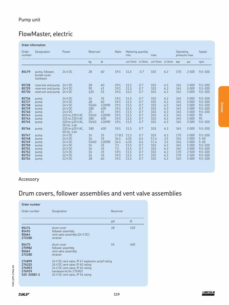
119
PU
B L
S/P
1 1
7046 E
N
Grea
se
Pump unit
FlowMaster, electric
Order information
Order number
Designation Power Reservoir Ratio Metering quantitymin.
max.
Operating pressure max.
Speed
kg lb cm³/min in³/min cm³/min in³/min bar psi rpm
85479 pump, follower,bucket cover, hardware
24 V DC 28 60 19:1 11,5 0.7 103 6.3 170 2 500 9,5-100
85728 reservoir and pump 24 V DC 28 60 19:1 11,5 0.7 103 6.3 345 5 000 9,5-10085729 reservoir and pump 24 V DC 90 41 19:1 11,5 0.7 103 6.3 345 5 000 9,5-10085730 reservoir and pump 24 V DC 120 55 19:1 11,5 0.7 103 6.3 345 5 000 9,5-100
85736 pump 24 V DC 16 35 19:1 11,5 0.7 103 6.3 345 5 000 9,5-10085737 pump 24 V DC 28 60 19:1 11,5 0.7 103 6.3 345 5 000 9,5-10085738 pump 24 V DC 55/40 120/90 19:1 11,5 0.7 103 6.3 345 5 000 9,5-10085739 pump 24 V DC 180 400 19:1 11,5 0.7 103 6.3 345 5 000 9,5-10085740 pump 24 V DC 25 55 19:1 11,5 0.7 103 6.3 345 5 000 9,5-10085743 pump 115 to 230 V AC 55/40 120/90 19:1 11,5 0.7 103 6.3 345 5 000 9585744 pump 115 to 230 V AC 180 400 19:1 11,5 0.7 103 6.3 345 5 000 9585745 pump 220 to 420 V AC,
50 Hz, 3 ph55/40 120/90 19:1 11,5 0.7 103 6.3 345 5 000 9,5-100
85746 pump 220 to 420 V AC, 50 Hz, 3 ph
180 400 19:1 11,5 0.7 103 6.3 345 5 000 9,5-100
85747 pump 24 V DC 16 35 17.8:1 11,5 0.7 103 6.3 170 5 000 9,5-10085748 pump 24 V DC 16 35 34:1 6,55 0.4 57,4 3.5 345 5 000 5-5085749 pump 24 V DC 55/40 120/90 34:1 6,55 0.4 57,4 3.5 345 5 000 5-5085750 pump 24 V DC 16 35 7:1 11,5 0.7 103 6.3 345 5 000 9,5-10085751 pump 24 V DC 16 35 7:1 11,5 0.7 103 6.3 345 5 000 9,5-10085752 pump 12 V DC 16 35 19:1 11,5 0.7 103 6.3 170 2 500 9,5-10085753 pump 12 V DC 16 35 19:1 11,5 0.7 103 6.3 170 2 500 9,5-10085754 pump 12 V DC 28 60 19:1 11,5 0.7 103 6.3 345 5 000 9,5-100
Order number
Order number Designation Reservoir
gal lb
85474 drum cover 18 12085492 follower assembly85664 vent valve assembly (24 V DC)272180 strainer
85475 drum cover 55 400270982 follower assembly85665 vent valve assembly272180 strainer
274899 24 V DC vent valve, IP 67 explosion-proof rating276325 24 V DC vent valve, IP 65 rating276903 24 V DC vent valve, IP 65 rating276919 hardware kit for 276903525-32083-1 24 V DC vent valve, IP 54 rating
Accessory
Drum covers, follower assemblies and vent valve assemblies
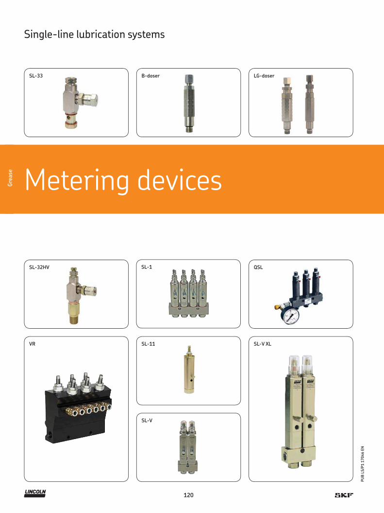
120
PU
B L
S/P
1 1
7046 E
N
Gre
ase
Metering devicesGre
ase
Single-line lubrication systems
SL-V
SL-V XL
QSL
VR SL-11
LG-doser
SL-32HV SL-1
SL-33 B-doser
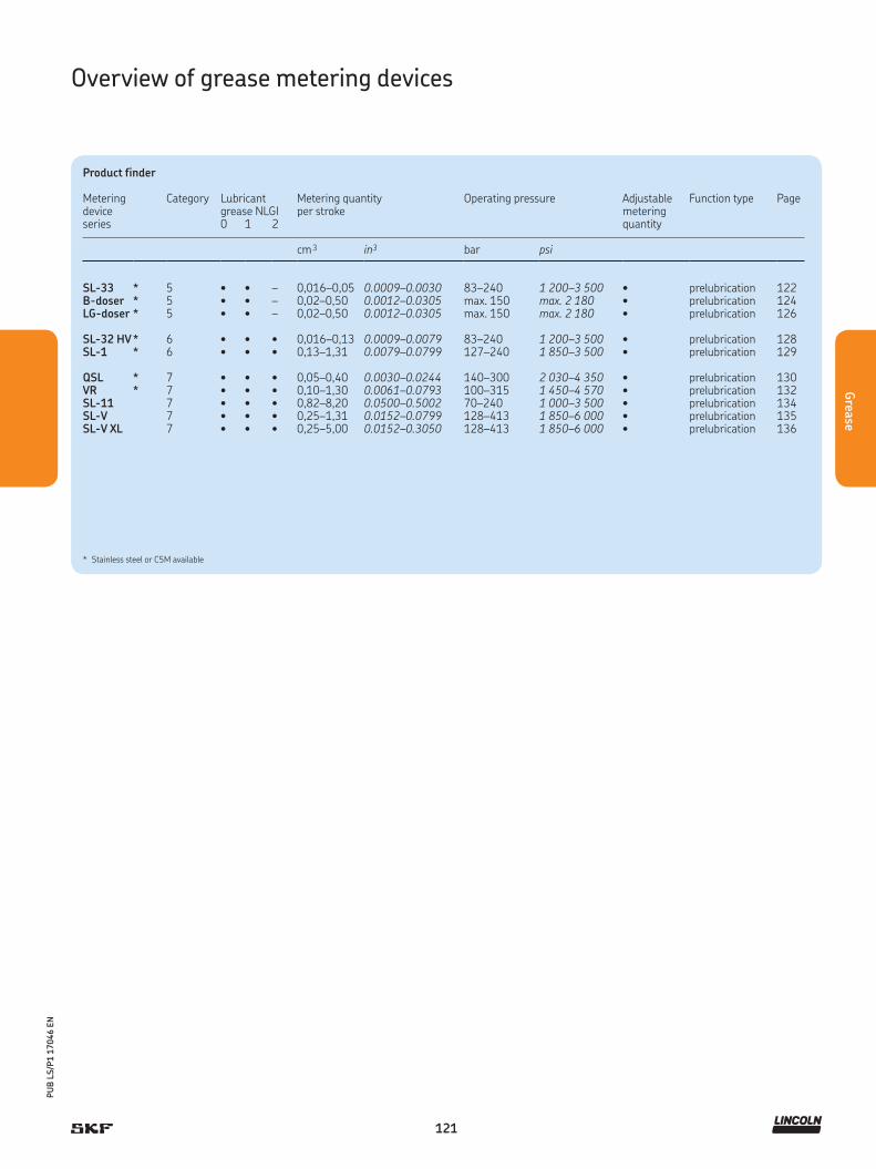
121
PU
B L
S/P
1 1
7046 E
N
Grea
se
Overview of grease metering devices
Product finder
Metering device series
Category Lubricant Metering quantity Operating pressure Adjustable Function type Pagegrease NLGI per stroke metering0 1 2 quantity
cm 3 in3 bar psi
SL-33 * 5 • • – 0,016–0,05 0.0009–0.0030 83–240 1 200–3 500 • prelubrication 122B-doser * 5 • • – 0,02–0,50 0.0012–0.0305 max. 150 max. 2 180 • prelubrication 124LG-doser * 5 • • – 0,02–0,50 0.0012–0.0305 max. 150 max. 2 180 • prelubrication 126
SL-32 HV * 6 • • • 0,016–0,13 0.0009–0.0079 83–240 1 200–3 500 • prelubrication 128SL-1 * 6 • • • 0,13–1,31 0.0079–0.0799 127–240 1 850–3 500 • prelubrication 129
QSL * 7 • • • 0,05–0,40 0.0030–0.0244 140–300 2 030–4 350 • prelubrication 130VR * 7 • • • 0,10–1,30 0.0061–0.0793 100–315 1 450–4 570 • prelubrication 132SL-11 7 • • • 0,82–8,20 0.0500–0.5002 70–240 1 000–3 500 • prelubrication 134SL-V 7 • • • 0,25–1,31 0.0152–0.0799 128–413 1 850–6 000 • prelubrication 135SL-V XL 7 • • • 0,25–5,00 0.0152–0.3050 128–413 1 850–6 000 • prelubrication 136
* Stainless steel or C5M available

122
PU
B L
S/P
1 1
7046 E
N
Gre
ase
Technical data
Function principle . . . . . . . metering deviceOutlets. . . . . . . . . . . . . . . . 1 to 4Metering quantity . . . . . . . 0,016 to 0,049 cm 3
0.001 to 0.003 in³Lubricant . . . . . . . . . . . . . grease NLGI 0, 1Operating temperature . . . max. +93 °C; +200 °F Operating pressure . . . . . .
Relief pressure. . . . . . . . . .
83 to 240 bar, 1 200 to 3 500 psi typical: 100 bar, 1 500 psi14 bar, 200 psi
Materials . . . . . . . . . . . . . . carbon steel, stainless steel 304Connection main line . . . . . 1/8 NPTF (F), 1/8 NPTF (M)Connection outlet 1/8 in O.D. tubeLubricant point . . . . . . . . . solderless pipe connection (DIN 3862)
or plug connectorDimensions . . . . . . . . . . . . min. 41 × 62 × 43 mm
max. 156 × 62 × 43 mmmin. 1.6 × 2.4 × 1.7 inmax. 6.1 × 2.4 × 1.7 in
Mounting position . . . . . . . any
Metering device
SL-33
Metering devices, except replacement metering devices for manifold, include compression nut and ferrule for tubing, 3,175 mm (0.125 in) O.D. as standard. Other outlet connectors for feedline optional; metering devices with manifolds include two mounting clips and screws; meteringdevices have nitrile packings. Check packing compatibility with synthetic lubricants; output withindicator cap hand-tightened is 0,016 cm³ (0.001 in³). Maximum output is achieved with twoturns at 0,016 cm³ / turn (0.001 in³ / turn)
Product description
The series SL-33 metering devices are for single-line, high-pres-
sure centralized lubrication systems dispensing petroleum-based
lubricants with a viscosity up to NLGI 2. Output is externally adjust-
able. Its indicator stem permits visual check of metering device op-
eration. May be combined in a circuit of metering devices SL-32,
SL-V, SL-V XL, SL-1 and/or SL-11. Individual metering devices can
be removed easily for inspection or replacement. Available in stain-
less steel SAE 304 for applications where environmental conditions
are hazardous to carbon steel or in industries preferring stainless
steel.
Features and benefits
• For use with manifolds from 1 to 7 ports to match
number of lube points
• Output is externally adjustable
• Can be removed easily for inspection or replacement
Applications
• Food and beverage

123
PU
B L
S/P
1 1
7046 E
N
Grea
se
SL-33
Order number 1) Designation Material Outlets Manifold inlet
83309-1 metering device including manifold carbon steel 1 1/8 NPTF (F)83309-2 metering device including manifold carbon steel 2 1/8 NPTF (F)83309-3 metering device including manifold carbon steel 3 1/8 NPTF (F)83309-4 metering device including manifold carbon steel 4 1/8 NPTF (F)83309-5 metering device including manifold carbon steel 5 1/8 NPTF (M)83309-6 metering device including manifold carbon steel 6 1/8 NPTF (F)
83900 single metering device, no manifold needed carbon steel 1 1/8 NPTF (M)83314 single metering device for replacement carbon steel – –
83715-1 metering device including manifold stainless steel 304 1 1/8 NPTF (F)83715-2 metering device including manifold stainless steel 304 2 1/8 NPTF (F)83715-3 metering device including manifold stainless steel 304 3 1/8 NPTF (F)83715-4 metering device including manifold stainless steel 304 4 1/8 NPTF (F)
83715-6 metering device including manifold stainless steel 304 6 1/8 NPTF (F)83715-7 metering device including manifold stainless steel 304 7 1/8 NPTF (F)83900-9 single metering device, no manifold needed stainless steel 304 1 1/8 NPTF (M)83314-9 single metering device for replacement stainless steel 304 – –
Metering device
SL-33

124
PU
B L
S/P
1 1
7046 E
N
Gre
ase
Product description
B-dosers are used in single-line, heavy vehicle and industrial
lubrication applications. The doser group consists of a mounting rail
with one or more dosers attached to it. Dosing modules and mount-
ing rails are made of zinc-coated and yellow-passivated steel.
The dosage ranges of B-dosers are from 20 to 500 mm 3.
Features and benefits
• The output quantity of the used dosers is visible
on amount of notches at the housing
• Suitable with optionally manifold sizes for 2-, 3- and
6-ports to match amout of lube points (1-6)
• Material of manifold : stainless steel AISI 303
• Suits for ø 4 and 6 mm of feedlines
Applications
• Heavy vehicles
• Heavy industrial application
Technical data
Function principle . . . . . . . metering deviceOutlets. . . . . . . . . . . . . . . . 1 to 6Metering quantity . . . . . . . 0,02 to 0,50 cm 3, 0.0012 to 0.0305 in³Lubricant . . . . . . . . . . . . . oil and grease NLGI 000 to 1Operating temperature . . . –25 to +80 °C; –13 to +176 °FOperating pressure . . . . . . max. 150 bar, 2 180 psi Relief pressure. . . . . . . . . . B1, B2=15 bar; 218 psi
B3, B4=10 bar; 145 psiB5, B6=5 bar; 72 psi
Materials . . . . . . . . . . . . . . zinc-coated and yellow-passivated steelConnection main line(manifold) . . . . . . . . . . . . . R 1/4 for ø 8 mm or pipe ø 1/2 inConnection outlet . . . . . . . 1/8 NPT(F) for ø 4 and 6 mm feedlinesLubricant point . . . . . . . . . solderless pipe connection, DIN 3862Dimensions . . . . . . . . . . . . min. 15 × 90 × 15 mm
max. 17 × 110 × 17 mmmin. 0.6 × 3.5 × 0.6 inmax. 0.7 × 4.3 × 0.7 in
Mounting position . . . . . . . any
!NOTE
For further technical information, technical drawings,
accessories, spare parts or product function descriptions,
see the following publication available on
SKF.com/lubrication: 11276 EN
Metering device
B-doser

125
PU
B L
S/P
1 1
7046 E
N
Grea
se
Metering device
B-doser
Order number configurator B – G 1 / 8 – Z N –
Product series
Metering quantity
1 = 0,02 cm 3, 0.0012 in3
2 = 0,05 cm 3, 0.0030 in3
3 = 0,10 cm 3, 0.0061 in3
4 = 0,15 cm 3, 0.0091 in3
5 = 0,20 cm 3, 0.0122 in3
6 = adjustable 0,2 to 0,5 cm³; 0.012 to 0.03 in³
Mounting rail fitting
G1/8 = G 1/8 fitting
Material
ZN = zinc-coated steel
Lubricant outlet
4 = pipe connector ø 4 mm6 = pipe connector ø 6 mm- = pipe connector mmU = female thread NPT 1/8
Order number configurator B P L D – –
Mounting rail, baseplate
Lubrication system type, LD
Mounting rail size
02 = 2-place mounting rail04 = 4-place mounting rail06 = 6-place mounting rail0202 = 4-place mounting rail, 2 places on opposite sides0303 = 6-place mounting rail, 3 places on opposite sides
Material mounting rail
ZN = Zinc-coated and yellow-passivated steel
Accessory
Manifold
Product description
For B-doser metering devices, manifolds
utilized are for 1 to 6 screw-in points with
thread G 1/8 for O-ring sealing . Mainline
fitting for G 1/4 for ø 8 mm or pipe ø 1/2 in.
Normal profile and opposite-side profile de-
sign manifolds are available in zinc-coated
and yellow-passivated steel. Various designs
of main line and feed line connection can be
selected by order code.

126
PU
B L
S/P
1 1
7046 E
N
Gre
ase
Product description
LG-dosers are used in single-line lubrication applications. The doser
group consists of a mounting rail with one or more dosers attached
to it. Dosing modules and mounting rails are made of stainless steel.
Features and benefits
• Two adjustable doser sizes are selectable
by the used output quantity
• Manifold material: stainless steel AISI 303
• Compatible with for screw-in type fittings
for dosers and manifolds
• Suitable for feed line ø 4 and ø 6 mm
• Robust and reliable
Applications
• Food and beverage
Technical data
Function principle . . . . . . . metering deviceOutlets. . . . . . . . . . . . . . . . 1 to 6 Metering quantity . . . . . . . 0,02 to 0,50 cm 3; 0.0012 to 0.0305 in³Lubricant . . . . . . . . . . . . . oil and grease NLGI 000 to 1Operating temperature . . . –25 to +80 °C; –13 to +176 °FOperating pressure . . . . . . max. 150 bar, 2 180 psi Relief pressure. . . . . . . . . . LG001=10 bar; 145 psi
LG002=5 bar; 72 psiMaterials . . . . . . . . . . . . . . stainless steel AISI 304Connection main line . . . . . manifold: R 1/4 inConnection outlet . . . . . . . pipe connector ø 4 and 6 mm
or pipe ø 1/4 inConnection lubricant point. solderless pipe connection (DIN 3862)Material . . . . . . . . . . . . . . . stainless steel AISI 303Dimensions . . . . . . . . . . . . min. 15 × 112 × 15 mm
max. 17 × 110 × 17 mm min. 0.6 × 4.4 × 0.6 inmax. 0.7 × 4.3 × 0.7 in
Mounting position . . . . . . . any
!NOTE
For further technical information, technical drawings,
accessories, spare parts or product function descriptions,
see the following publication available on
SKF.com/lubrication: 11276 EN
Metering device
LG-doser
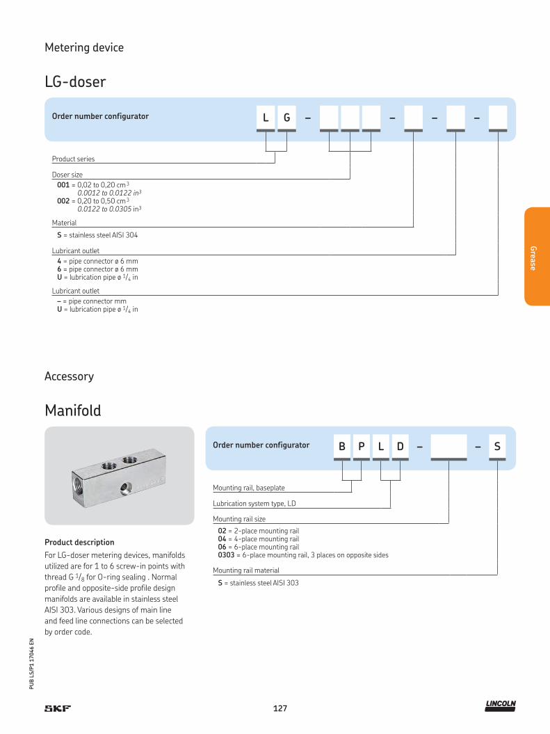
127
PU
B L
S/P
1 1
7046 E
N
Grea
se
Metering device
LG-doser
Order number configurator L G – – – –
Product series
Doser size
001 = 0,02 to 0,20 cm 3 0.0012 to 0.0122 in3
002 = 0,20 to 0,50 cm 3 0.0122 to 0.0305 in3
Material
S = stainless steel AISI 304
Lubricant outlet
4 = pipe connector ø 6 mm6 = pipe connector ø 6 mmU = lubrication pipe ø 1/4 in
Lubricant outlet
– = pipe connector mmU = lubrication pipe ø 1/4 in
Order number configurator B P L D – – S
Mounting rail, baseplate
Lubrication system type, LD
Mounting rail size
02 = 2-place mounting rail04 = 4-place mounting rail06 = 6-place mounting rail0303 = 6-place mounting rail, 3 places on opposite sides
Mounting rail material
S = stainless steel AISI 303
Accessory
Manifold
Product description
For LG-doser metering devices, manifolds
utilized are for 1 to 6 screw-in points with
thread G 1/8 for O-ring sealing . Normal
profile and opposite-side profile design
manifolds are available in stainless steel
AISI 303. Various designs of main line
and feed line connections can be selected
by order code.
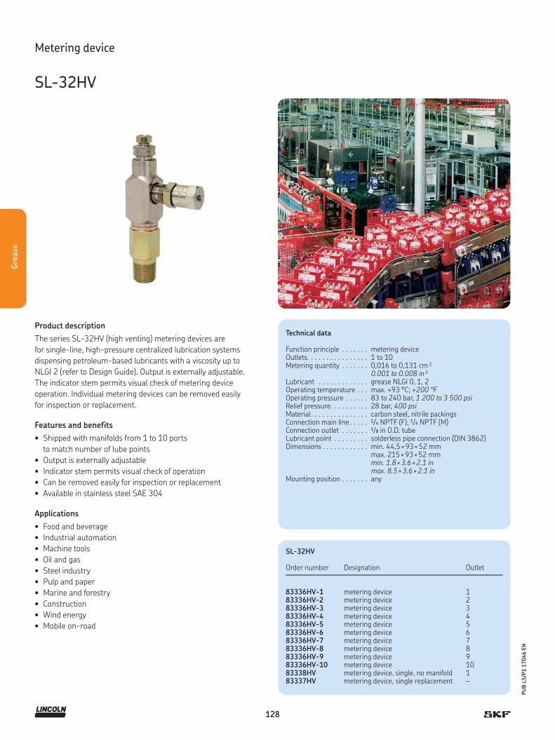
128
PU
B L
S/P
1 1
7046 E
N
Gre
ase
Product description
The series SL-32HV (high venting) metering devices are
for single-line, high-pressure centralized lubrication systems
dispensing petroleum-based lubricants with a viscosity up to
NLGI 2 (refer to Design Guide). Output is externally adjustable.
The indicator stem permits visual check of metering device
operation. Individual metering devices can be removed easily
for inspection or replacement.
Features and benefits
• Shipped with manifolds from 1 to 10 ports
to match number of lube points
• Output is externally adjustable
• Indicator stem permits visual check of operation
• Can be removed easily for inspection or replacement
• Available in stainless steel SAE 304
Applications
• Food and beverage
• Industrial automation
• Machine tools
• Oil and gas
• Steel industry
• Pulp and paper
• Marine and forestry
• Construction
• Wind energy
• Mobile on-road
Technical data
Function principle . . . . . . . metering deviceOutlets. . . . . . . . . . . . . . . . 1 to 10Metering quantity . . . . . . . 0,016 to 0,131 cm 3
0.001 to 0.008 in³Lubricant . . . . . . . . . . . . . grease NLGI 0, 1, 2Operating temperature . . . max. +93 °C; +200 °F Operating pressure . . . . . . 83 to 240 bar, 1 200 to 3 500 psiRelief pressure. . . . . . . . . . 28 bar, 400 psiMaterial . . . . . . . . . . . . . . . carbon steel, nitrile packingsConnection main line . . . . . 1/4 NPTF (F), 1/4 NPTF (M)Connection outlet . . . . . . . 1/8 in O.D. tubeLubricant point . . . . . . . . . solderless pipe connection (DIN 3862)Dimensions . . . . . . . . . . . . min. 44,5 × 93 × 52 mm
max. 215 × 93 × 52 mmmin. 1.8 × 3.6 × 2.1 inmax. 8.5 × 3.6 × 2.1 in
Mounting position . . . . . . . any
Metering device
SL-32HV
SL-32HV
Order number Designation Outlet
83336HV-1 metering device 183336HV-2 metering device 283336HV-3 metering device 383336HV-4 metering device 483336HV-5 metering device 583336HV-6 metering device 683336HV-7 metering device 783336HV-8 metering device 883336HV-9 metering device 983336HV-10 metering device 1083338HV metering device, single, no manifold 183337HV metering device, single replacement –
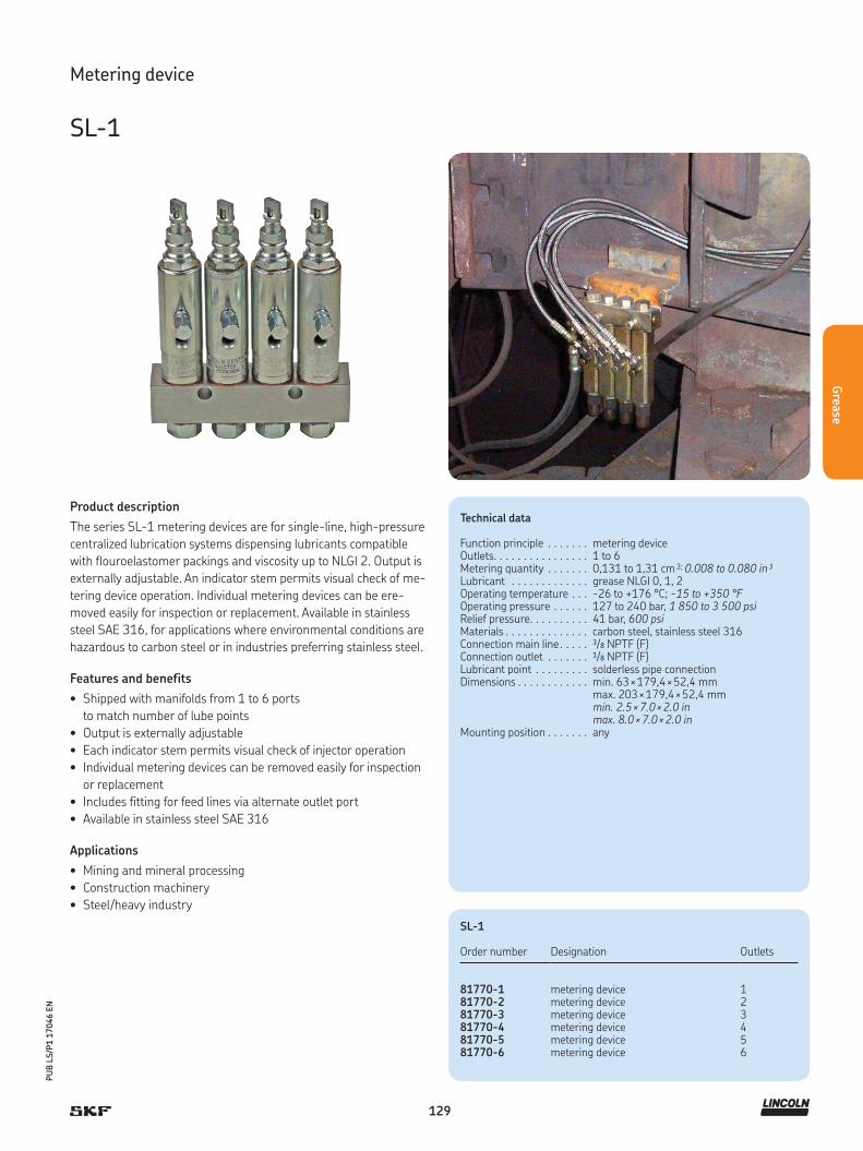
129
PU
B L
S/P
1 1
7046 E
N
Grea
se
Product description
The series SL-1 metering devices are for single-line, high-pressure
centralized lubrication systems dispensing lubricants compatible
with flouroelastomer packings and viscosity up to NLGI 2. Output is
externally adjustable. An indicator stem permits visual check of me-
tering device operation. Individual metering devices can be ere-
moved easily for inspection or replacement. Available in stainless
steel SAE 316, for applications where environmental conditions are
hazardous to carbon steel or in industries preferring stainless steel.
Features and benefits
• Shipped with manifolds from 1 to 6 ports
to match number of lube points
• Output is externally adjustable
• Each indicator stem permits visual check of injector operation
• Individual metering devices can be removed easily for inspection
or replacement
• Includes fitting for feed lines via alternate outlet port
• Available in stainless steel SAE 316
Applications
• Mining and mineral processing
• Construction machinery
• Steel/heavy industry
Technical data
Function principle . . . . . . . metering deviceOutlets. . . . . . . . . . . . . . . . 1 to 6Metering quantity . . . . . . . 0,131 to 1,31 cm 3; 0.008 to 0.080 in³Lubricant . . . . . . . . . . . . . grease NLGI 0, 1, 2Operating temperature . . . -26 to +176 °C; -15 to +350 °F Operating pressure . . . . . . Relief pressure. . . . . . . . . .
127 to 240 bar, 1 850 to 3 500 psi 41 bar, 600 psi
Materials . . . . . . . . . . . . . . carbon steel, stainless steel 316Connection main line . . . . . 3/8 NPTF (F)Connection outlet . . . . . . . 1/8 NPTF (F)Lubricant point . . . . . . . . . solderless pipe connectionDimensions . . . . . . . . . . . . min. 63 × 179,4 × 52,4 mm
max. 203 × 179,4 × 52,4 mmmin. 2.5 × 7.0 × 2.0 inmax. 8.0 × 7.0 × 2.0 in
Mounting position . . . . . . . any
Metering device
SL-1
SL-1
Order number Designation Outlets
81770-1 metering device 181770-2 metering device 281770-3 metering device 381770-4 metering device 481770-5 metering device 581770-6 metering device 6
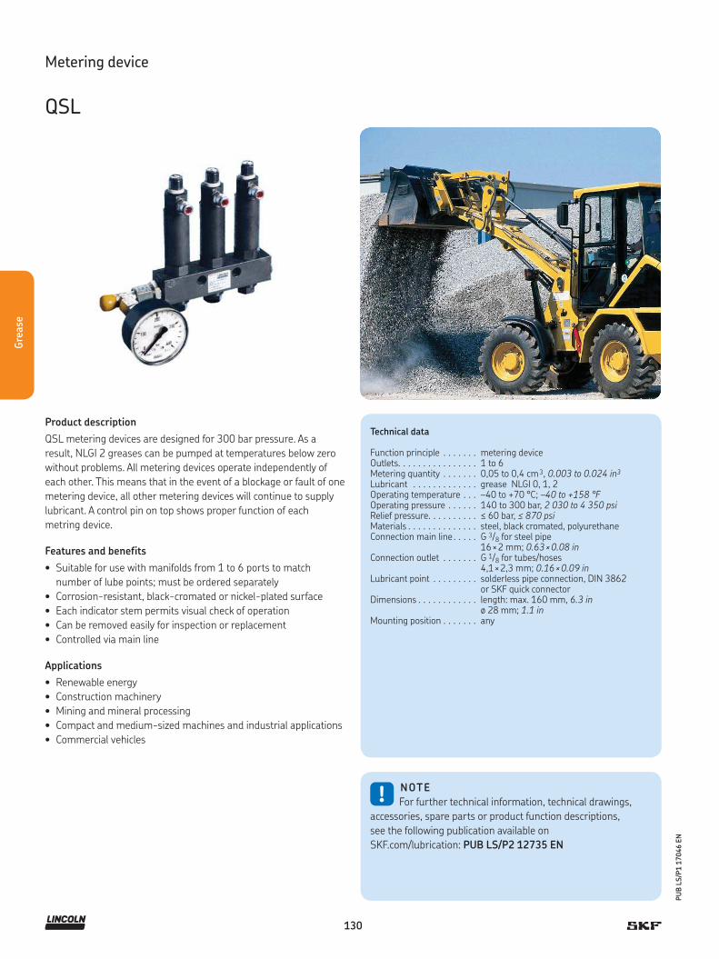
130
PU
B L
S/P
1 1
7046 E
N
Gre
ase
Product description
QSL metering devices are designed for 300 bar pressure. As a
result, NLGI 2 greases can be pumped at temperatures below zero
without problems. All metering devices operate independently of
each other. This means that in the event of a blockage or fault of one
metering device, all other metering devices will continue to supply
lubricant. A control pin on top shows proper function of each
metring device.
Features and benefits
• Suitable for use with manifolds from 1 to 6 ports to match
number of lube points; must be ordered separately
• Corrosion-resistant, black-cromated or nickel-plated surface
• Each indicator stem permits visual check of operation
• Can be removed easily for inspection or replacement
• Controlled via main line
Applications
• Renewable energy
• Construction machinery
• Mining and mineral processing
• Compact and medium-sized machines and industrial applications
• Commercial vehicles
!NOTE
For further technical information, technical drawings,
accessories, spare parts or product function descriptions,
see the following publication available on
SKF.com/lubrication: PUB LS/P2 12735 EN
Metering device
QSL
Technical data
Function principle . . . . . . . metering deviceOutlets. . . . . . . . . . . . . . . . 1 to 6Metering quantity . . . . . . . 0,05 to 0,4 cm 3, 0.003 to 0.024 in3
Lubricant . . . . . . . . . . . . . grease NLGI 0, 1, 2Operating temperature . . . –40 to +70 °C; –40 to +158 °FOperating pressure . . . . . . 140 to 300 bar, 2 030 to 4 350 psiRelief pressure. . . . . . . . . . ≤ 60 bar, ≤ 870 psiMaterials . . . . . . . . . . . . . . steel, black cromated, polyurethaneConnection main line . . . . . G 3/8 for steel pipe
16 × 2 mm; 0.63 × 0.08 inConnection outlet . . . . . . . G 1/8 for tubes/hoses
4,1 × 2,3 mm; 0.16 × 0.09 inLubricant point . . . . . . . . . solderless pipe connection, DIN 3862
or SKF quick connectorDimensions . . . . . . . . . . . . length: max. 160 mm, 6.3 in
ø 28 mm; 1.1 inMounting position . . . . . . . any

131
PU
B L
S/P
1 1
7046 E
N
Grea
se
OSL
Order number 1) DesignationInjectors
Metering quantity per stroke
Ring color
cm 3 in3
554-32810-1 QSL 0,05 0,05 0.00305 blue554-32811-1 QSL 0,1 0,10 0.00610 white554-32812-1 QSL 0,2 0,20 0.01220 yellow554-32813-1 QSL 0,3 0,30 0.01830 red554-32814-1 QSL 0,4 0,40 0.02440 green
Metering device
QSL
Check valves and closure kit
Order number Designation
223-12289-7 check valves for connection at lubrication point outlets
554-34387-1 closure kit 5
Accessory
Manifold, check valves and closure kit
Manifolds 1)
Order number Designation Dimensionsfixing hole length, total
mm in mm in
454-71505-1 divider bar, 2-fold 74 2.91 130 5.11454-71506-1 divider bar, 3-fold 42 1.65 130 5.11454-71507-1 divider bar, 4-fold 84 3.30 172 6.77454-71508-1 divider bar, 5-fold 126 4.96 214 8.42454-71509-1 divider bar, 6-fold 84 1) 3.30 256 10.07
1) Instead of the planned injectors a divider bar can also be equipped with a closure kit 5, order number: 554-34387-12) 3 bores
Product description
For QLS metering devices, manifolds utilized
are for 1 to 6 push-in points tightened by a
hollow screw with thread G 3/8 for O-ring
sealing. Normal profile design manifolds are
available in steel. The main line connection
G 3/8 is for steel pipe 16 × 2 mm (0.63 × 0.08
in). The lubrication connection is for plastic
tube 4,1 × 2,3 mm; (0.16 × 0.09 in) .
1) In the case of backpressures in lubrication point lines of ≥ 100 bar or if several injectors are combined to one lubrication point, use check valves, order number 223-12289-7.
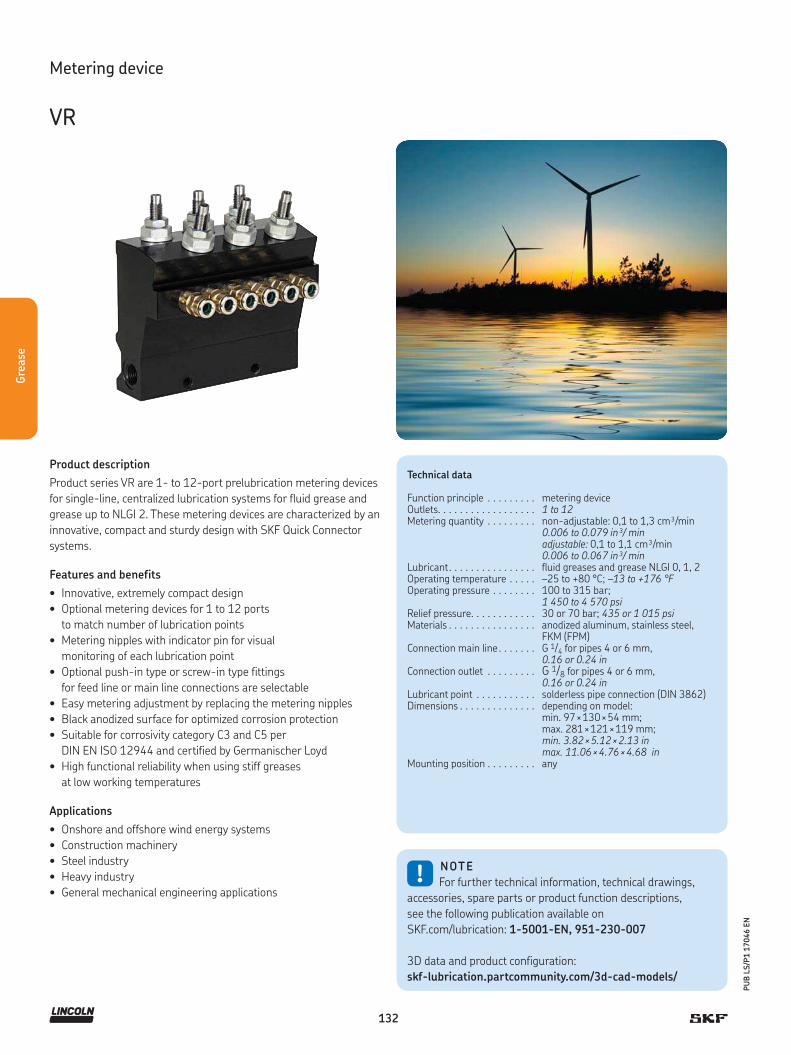
132
PU
B L
S/P
1 1
7046 E
N
Gre
ase
Product description
Product series VR are 1- to 12-port prelubrication metering devices
for single-line, centralized lubrication systems for fluid grease and
grease up to NLGI 2. These metering devices are characterized by an
innovative, compact and sturdy design with SKF Quick Connector
systems.
Features and benefits
• Innovative, extremely compact design
• Optional metering devices for 1 to 12 ports
to match number of lubrication points
• Metering nipples with indicator pin for visual
monitoring of each lubrication point
• Optional push-in type or screw-in type fittings
for feed line or main line connections are selectable
• Easy metering adjustment by replacing the metering nipples
• Black anodized surface for optimized corrosion protection
• Suitable for corrosivity category C3 and C5 per
DIN EN ISO 12944 and certified by Germanischer Loyd
• High functional reliability when using stiff greases
at low working temperatures
Applications
• Onshore and offshore wind energy systems
• Construction machinery
• Steel industry
• Heavy industry
• General mechanical engineering applications
Technical data
Function principle . . . . . . . . . metering deviceOutlets. . . . . . . . . . . . . . . . . . 1 to 12Metering quantity . . . . . . . . . non-adjustable: 0,1 to 1,3 cm³/min
0.006 to 0.079 in³/ minadjustable: 0,1 to 1,1 cm³/min0.006 to 0.067 in³/ min
Lubricant. . . . . . . . . . . . . . . . fluid greases and grease NLGI 0, 1, 2Operating temperature . . . . . –25 to +80 °C; –13 to +176 °FOperating pressure . . . . . . . . 100 to 315 bar;
1 450 to 4 570 psiRelief pressure. . . . . . . . . . . . 30 or 70 bar; 435 or 1 015 psiMaterials . . . . . . . . . . . . . . . . anodized aluminum, stainless steel,
FKM (FPM)Connection main line . . . . . . . G 1/4 for pipes 4 or 6 mm,
0.16 or 0.24 inConnection outlet . . . . . . . . . G 1/8 for pipes 4 or 6 mm,
0.16 or 0.24 inLubricant point . . . . . . . . . . . solderless pipe connection (DIN 3862)Dimensions . . . . . . . . . . . . . . depending on model:
min. 97 × 130 × 54 mm; max. 281 × 121 × 119 mm;min. 3.82 × 5.12 × 2.13 inmax. 11.06 × 4.76 × 4.68 in
Mounting position . . . . . . . . . any
!NOTE
For further technical information, technical drawings,
accessories, spare parts or product function descriptions,
see the following publication available on
SKF.com/lubrication: 1-5001-EN, 951-230-007
3D data and product configuration:
skf-lubrication.partcommunity.com/3d-cad-models/
Metering device
VR

133
PU
B L
S/P
1 1
7046 E
N
Grea
se
Metering device
VR
Order code V R
Product series
Number of metering points 1 2 3 4 5 6 7 8 9 10 11 12
01 = 102 = 203 = 304 = 405 = 506 = 6
07 = 708 = 809 = 910 = 1011 = 1112 = 12
Design for fluid grease and grease
Design code letter A B C D E F G H N P
Max. relief pressure [bar] 30 70 30 70 30 70 30 70 30 70
Secondary line connection G 1/8 G 1/8 VS VS VS VS G 1/8 G 1/8 SRV1) SRV1)
Secondary line ø[mm] – – 4 4 6 6 – – 6 6
Corrosivity category 2) C3 C3 C3 C3 C3 C3 C5-M C5-M C5-M C5-M
Fittings for main line connection
Left fitting Right fittingø Mainline [mm] Code
Cutting-sleevescrew union*
Cutting-sleevescrew union*
810
AG
Cutting-sleevescrew union*
Closed 810
BH
Closed Cutting-sleevescrew union
810
CJ
EO-2 screw union EO-2 screw union 8 D10 K
EO-2 screw union Closed 8 E10 L
Closed EO-2 screw union 8 F10 M
G 1/4 G 1/4 – Z
Cod
e le
tter
Met
erin
g qu
antity
lett
er(0
= n
ot p
rese
nt, e
.g. f
or V
R06 a
ssig
n 0
for
met
erin
g poi
nts
7–1
2)
Metering
Metering quantity letter A 1) B 1) D 1) F 1) H 1) J 1) M 1) R 2) X
Metering [cm³] 0,1 0,2 0,4 0,6 0,8 1 1,3 0,1–1,1 Closed
Cod
e fo
r fit
tings
for
mai
n li
ne
connec
tion
1) SRV = cutting-sleeve screw union, see page 22) Corrosivity categories per DIN EN ISO 12944 (certified by Germanischer Lloyd)
1) Fixed metering with indicator pin for visual function monitoring2) Adjustable metering with indicator pin for visual function monitoring
Order example
VR06FFFFFFF000000Z• Single-line distributor, 6-port• Relief pressure max. 70 bar• Lubrication point line connection using SKF plug connector
for pipe ø 6 mm• Metering quantity 1 – 6 = 0,6 cm³• Without fitting for main line connection (G 1/4 thread)
Left Right
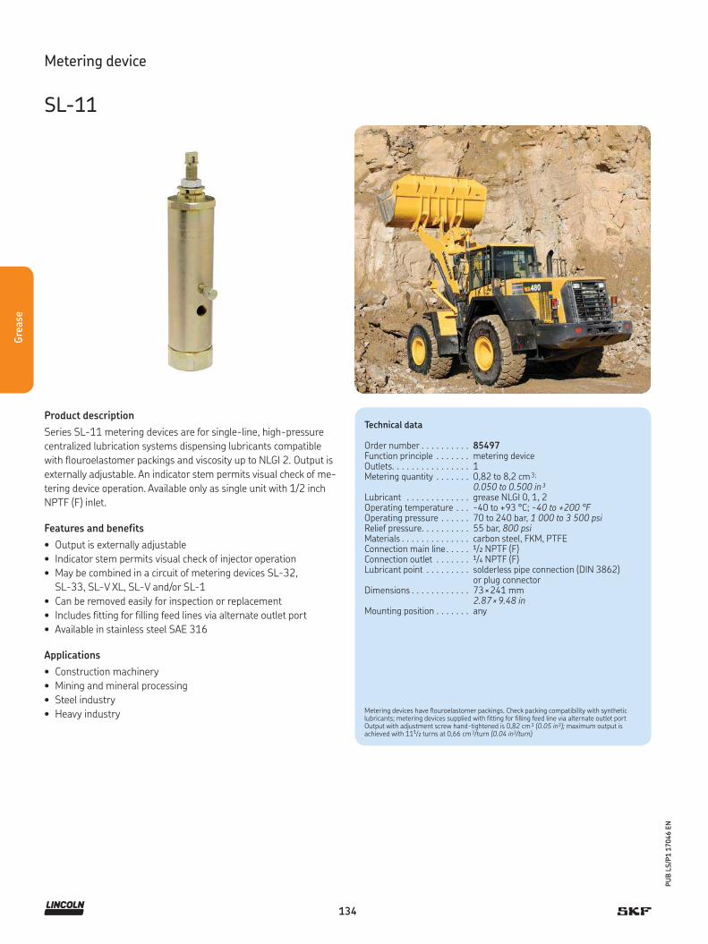
134
PU
B L
S/P
1 1
7046 E
N
Gre
ase
Product description
Series SL-11 metering devices are for single-line, high-pressure
centralized lubrication systems dispensing lubricants compatible
with flouroelastomer packings and viscosity up to NLGI 2. Output is
externally adjustable. An indicator stem permits visual check of me-
tering device operation. Available only as single unit with 1/2 inch
NPTF (F) inlet.
Features and benefits
• Output is externally adjustable
• Indicator stem permits visual check of injector operation
• May be combined in a circuit of metering devices SL-32,
SL-33, SL-V XL, SL-V and/or SL-1
• Can be removed easily for inspection or replacement
• Includes fitting for filling feed lines via alternate outlet port
• Available in stainless steel SAE 316
Applications
• Construction machinery
• Mining and mineral processing
• Steel industry
• Heavy industry
Technical data
Order number . . . . . . . . . . 85497Function principle . . . . . . . metering deviceOutlets. . . . . . . . . . . . . . . . 1Metering quantity . . . . . . . 0,82 to 8,2 cm 3;
0.050 to 0.500 in³Lubricant . . . . . . . . . . . . . grease NLGI 0, 1, 2Operating temperature . . . -40 to +93 °C; -40 to +200 °FOperating pressure . . . . . . Relief pressure. . . . . . . . . .
70 to 240 bar, 1 000 to 3 500 psi 55 bar, 800 psi
Materials . . . . . . . . . . . . . . carbon steel, FKM, PTFEConnection main line . . . . . 1/2 NPTF (F)Connection outlet . . . . . . . 1/4 NPTF (F)Lubricant point . . . . . . . . . solderless pipe connection (DIN 3862)
or plug connectorDimensions . . . . . . . . . . . . 73 × 241 mm
2.87 × 9.48 inMounting position . . . . . . . any
Metering device
SL-11
Metering devices have flouroelastomer packings. Check packing compatibility with syntheticlubricants; metering devices supplied with fitting for filling feed line via alternate outlet portOutput with adjustment screw hand-tightened is 0,82 cm 3 (0.05 in3); maximum output isachieved with 111/2 turns at 0,66 cm 3/turn (0.04 in3/turn)

135
PU
B L
S/P
1 1
7046 E
N
Grea
se
Product description
Series SL-V metering devices are for single-line, high-pressure
centralized lubrication systems dispensing lubricants compatible
with polyurethane seals up to NLGI 2. Output is externally adjust-
able. An indicator stem permits visual check of metering device op-
eration. Individual metering devices can be removed easily for in-
spection or replacement. Each SL-V metering device includes a
clear, polycarbonate protective cap.
Features and benefits
• Shipped with manifolds from 1 to 6 ports
• Output is externally adjustable
• Clear, polycarbonate protected cap over indicator stem permits
visual check of operation
• Can be removed easily for inspection or replacement
• Available in carbon steel or stainless steel SAE 304
• Output setting system by a set of color-coded sleeves
Applications
• Construction machinery
• Mining and mineral processing
• Steel industry
Technical data
Function principle . . . . . . . metering deviceOutlets. . . . . . . . . . . . . . . . 1 to 6Metering quantity . . . . . . . 0,25 to 1,31 cm 3
0.015 to 0.08 in³Lubricant . . . . . . . . . . . . . greases up to NLGI 0, 1, 2Operating temperature . . . max. +82 °C; +180 °F Operating pressure . . . . . . 128 to 413 bar, 1 850 to 6 000 psi
typical: 172 bar, 2 500 psiRelief pressure. . . . . . . . . . 70 bar, 1 000 psiMaterials . . . . . . . . . . . . . . carbon steelConnection main line . . . . . 3/8 NPTF (F)Connection outlet . . . . . . . 1/8 NPTF (F)Dimensions . . . . . . . . . . . . min. 63 × 222 × 35 mm
max. 203 × 222 × 35 mmmin. 2.5 × 8.7 × 1.4 inmax. 6.1 × 8.7 × 1.4 in
Mounting position . . . . . . . any
Metering device
SL-V
Metering device manifolds have 10,3 mm (0.4 in) dia. mounting holes for 9,5 mm (0.375 in) bolt;metering devices have polyurethane seals; check compatibility with synthetic lubricants; metering devices include fitting for filling feedlines via alternate outlet port; output with adjustment screw hand-tightened is 0,246 cm 3 (0.015 in3); maximum output is achieved with five turns at 0,229 cm 3/turn (0.014 in3/turn)
SL-V
Order number Outlets Designation
85770-1 1 One metering device manifold85770-2 2 Two metering device manifold85770-3 3 Three metering device manifold85770-4 4 Four metering device manifold85770-5 5 Five metering device manifold85770-6 6 Six metering device manifold85771 – Replacement for manifold metering device85772 – Single metering device, no manifold,
3/8 NPTF (M)

136
PU
B L
S/P
1 1
7046 E
N
Gre
ase
Product description
Series SL-V XL high-output metering devices are for single-line,
high-pressure centralized lubrication systems dispensing lubricants
compatible with polyurethane seals up to NLGI 2. Output is exter-
nally adjustable. An indicator stem permits visual check of metering
device operation. Individual metering devices can be removed easily
for inspection or replacement. Two SL-V XL metering devices are
required to replace one SL-11 metering device. Each SL-V XL
metering device includes a clear, polycarbonate protective cap.
Features and benefits
• Suitable for use with manifolds from 1 to 6 ports to
match number of lubrication points
• Output is externally adjustable
• Includes a clear, polycarbonate protective cap over indicator stem
that permits visual check of operation
• Can be removed easily for inspection or replacement
• Includes fitting for filling feed lines via alternate outlet port
• Available in carbon steel or stainless steel SAE 304
Applications
• Construction machinery
• Mining and mineral processing
• Heavy industry
Technical data
Function principle . . . . . . . metering deviceOutlets. . . . . . . . . . . . . . . . 1 to 6Metering quantity . . . . . . . 0,25 to 5,00 cm 3, 0.015 to 0.305 in³Lubricant . . . . . . . . . . . . . grease NLGI 0, 1, 2Operating temperature . . . –40 to +82 °C; –40 to +180 °FOperating pressure . . . . . . 128 to 413 bar; 1 850 to 6 000 psiRelief pressure. . . . . . . . . . 70 bar, 1 000 psiMaterials . . . . . . . . . . . . . . carbon steelConnection main line . . . . . 3/8 NPTF (F)Connection outlet . . . . . . . 1/8 NPTF (F)Lubricant point . . . . . . . . . solderless pipe connection (DIN 3862)
or plug connectorDimensions . . . . . . . . . . . . min. 63 × 284 × 35 mm
max. 203 × 284 × 35 mm min. 2.5 × 11.2 × 1.4 inmax. 6.1 × 11.2 × 1.4 in
Mounting position . . . . . . . any
Metering device
SL-V XL
Metering device manifolds have 10,3 mm (0.4 in) dia. mounting holes for 9,5 mm (0.375 in) bolt;metering devices have polyurethane seals. Check compatibility with synthetic lubricants; metering devices include fitting for filling feed lines via alternate outlet port; output with adjustment screw hand-tightened is 0,246 cm 3 (0.015 in3); maximum output is achieved with 20.5 turns at 0,229 cm 3/turn (0.014 in3/turn).

137
PU
B L
S/P
1 1
7046 E
N
Grea
se
Order number configurator 8 5 7 8 0 –
Product series, carbon steel
85781 = replacement for manifold metering device85782 = single metering device, no manifold; 9,5 mm NPTF (M), 0.375 NPTF (M) inlet
Outlets
1 = 12 = 23 = 34 = 45 = 56 = 6
Metering device
SL-V XL

138
Acc
esso
ries
PU
B L
S/P
1 1
7046 E
N
Controllers
Accessories for single-line lubrication systems
Acc
esso
ries
EXZT / IGZ IG502-2-E LC502 ST-1440 ST-1240-GRAPH ST-1100i
ST-102 84501 84015 85520 85535 85530
LMC 101 EOT-1/2 LMC 301 LMC 2
85525 85208 / 85209 HCC Flow sensor

139
PU
B L
S/P
1 1
7046 E
N
Accesso
ries
Overview of controllers
Controllers
Product Operating temperature
Voltage Adjustable Level Pagemonitoring
°C °F V DC V AC
EXZT2A02 0 to 60 32 to 140 12/24 120 • – 140EXZT2A05 0 to 60 32 to 140 12/24 120 • • 140EXZT2A07 0 to 60 32 to 140 12/24 120 • • 140
IGZ36-20 0 to 60 32 to 140 12/24 120 • – 140IGZ36-20-S6 0 to 60 32 to 140 12/24 120 • • 140IGZ38-30 0 to 60 32 to 140 12/24 120 – • 140IGZ38-30-S1 0 to 60 32 to 140 12/24 120 – • 140IGZ51-20-S3 0 to 60 32 to 140 12/24 120 – – 140
IG502-2-E -25 to +75 -13 to +167 12/24 – • • 142LC502 0 to 60 32 to 140 12/24 – • • 143
ST-1440 0 to 60 32 to 140 – 93–264 • • 144ST-1340 0 to 60 32 to 140 – 93–264 • • 144ST-1240-GRAPH 0 to 50 32 to 140 – 93–264 • • 145ST-1240-GRAPH-4 0 to 50 32 to 140 – 93–264 • • 145ST-1100i -20 to +60 -4 to +142 – 93-264 • • 146ST-102 -40 to +80 -40 to +176 12/24 – • • 147ST-102P -40 to +80 -40 to +176 12/24 – • • 148
84501 -18 to +54 0 to 130 – 120/230 • – 14984015 -18 to +55 0 to 131 12/24 – • – 15085520 -25 to +65 -13 to +150 – 120 • • 15185535 -40 to +65 -40 to +150 12/24 – • • 15285530 0 to 50 32 to 122 12/24 – • • 153
LMC 101 -40 to +65 -40 to +150 12/24 – • • 154EOT-1 -25 to +70 -13 to +158 12/24 – • • 155EOT-2 -25 to +70 -13 to +158 12/24 – • • 155
LMC 301 -40 to +70 -40 to +158 12/24 90–264 • • 156LMC 2 -10 to +70 14 to 158 12/24 230 • • 157
Connection and flow controllers
Product Designation Operating temperature
Voltage Page
°C °F V DC V AC
HCC Hose tear-off -25 to +70 -58 to +158 12/24 – 160Flow sensor Flow sensor +10 to +50 50 to 122 12/24 – 161
Controller kits
Product Designation Operating temperature
Voltage Adjustable Level Pagemonitoring
°C °F V DC V AC
85525 Kit: controller and pressure sensor -25 to +65 -13 to +150 – 120 • • 15885208 Kit: controller, pressure sensor, solenoid valve 0 to 50 32 to 122 – 110/120 • • 15985209 Kit: controller, pressure sensor, solenoid valve 0 to 50 32 to 122 – 220 • • 159

140
PU
B L
S/P
1 1
7046 E
N
Acc
esso
ries
Controller
EXZT / IGZ
Product description
Universal electronic control and monitoring devices are used in
single- line and progressive lubrication systems for stationary
industrial applications, installed in a switching cabinet or internally
in a compact lubrication unit. Two different versions are required:
+471 for 100 to 120 V AC and 200 to 240 V AC; and +472 for 24 V
DC and 24 V AC. The universal devices can be used as time-depend-
ent or pulse-dependent controllers. The main task is to initiate a
lubrication cycle after a set time. The devices also monitor the piston
strokes and run the pump during the lubrication time in clogged
operation. All devices have custom-built functions integrated and
can be configured to meet the requirements of the application.
Mentioned device models must be selected based on their special
function configuration and additional features according to the
user manual.
Features and benefits
• Easy installation via top hat rail mounting
• One unit for different operating modes such as timer,
counter and monitoring functions; other
features are adjustable
• Pulse generator/counter with adjustable interval time
• Time operation or machine clogged operation
• Pump run time limitation
• Monitoring of pressure build-up, contact (NO)
• Low-level control and EEPROM as an additional feature
Applications
• All single-line lubrication systems for stationary
industrial applications
!NOTE
For further technical information, technical drawings,
accessories, spare parts or product function descriptions,
see the following publication available on
SKF.com/lubrication: 1-1700-4-EN
Technical data
Function principle . . . . . . . . . . . Universal electronic control and monitoring device
Operating temperature . . . . . . . 0 to 60 °C 32 to 140 °F
Output voltage. . . . . . . . . . . . . . 24 V DC +10% /-15%Connector for class . . . . . . . . . . IIProtection class . . . . . . . . . . . . IP 30, clamps IP 20Dimensions . . . . . . . . . . . . . . . 70 × 75 × 110 mm
2.7 × 3 × 4.3 in
Version + 471Input voltage . . . . . . . . . . . . . . 100 – 120 V AC; 200 – 240 V ACInput current rated . . . . . . . . . . 70 mA / 35 mAPower input . . . . . . . . . . . . . . . 8 WFrequency . . . . . . . . . . . . . . . . . 50 – 60 HzFuse . . . . . . . . . . . . . . . . . . . . . max. 6.3 ASwitching current . . . . . . . . . . . max. 5 AInput voltage sensors . . . . . . . . 24 V DC
Version + 472Input voltage . . . . . . . . . . . . . . 20 to 24 V DC; 20 to 24 V ACInput current rated . . . . . . . . . . 75 mA at max. fan-out of 250 mAPower input . . . . . . . . . . . . . . . 5 WFrequency . . . . . . . . . . . . . . . . . DC or 50 – 60 HzFuse . . . . . . . . . . . . . . . . . . . . . max. 6.3 ASwitching current . . . . . . . . . . . max. 5 AInput voltage sensors . . . . . . . . 24 V DC

141
PU
B L
S/P
1 1
7046 E
N
Accesso
ries
Controller
EXZT / IGZ
Models
Order numberInput voltage
Adjustable monitoring time
Adjustable pump delay time
Monitoring of pressure relief, contact
Lubricant level monitoring, contact
Interval time extension
Early lubricant levelwarning, contact
Pulse monitoring
Activatable failure memory EEPROM
EXZT2A02+471 120 V DC • • NO 1) NO 1) • – – –
EXZT2A02+472 24 V AC • • NO 1) NO 1) • – – –
EXZT2A05+471 120 V DC • • – NC 2) • – • –
EXZT2A05+472 24 V AC • • – NC 2) • – • –
EXZT2A07+471 120 V DC • • – NC 2) • • – –
EXZT2A07+472 24 V AC • • – NC 2) • • – –
IGZ36-20+471 120 V DC • • NC 2) NO 1) – – – –
IGZ36-20+472 24 V AC • • NC 2) NO 1) – – – –
IGZ36-20-S6+471 120 V DC • • NC 2) NC 2) – – – –
IGZ36-20-S6+472 24 V DC • • NC 2) NC 2) – – – –
IGZ38-30+471 120 V DC – – – NC 2) – – – –
IGZ38-30+472 24 V DC – – – NC 2) – – – –
IGZ38-30-S1+471 120 V DC – – – NO 1) – – – –
IGZ38-30-S1+472 24 V DC – – – NO 1) – – – –
IGZ51-20-S3+471 120 V DC • • NC 2) NO 1) • – – •
IGZ51-20-S3+472 24 V DC • • NC 2) NO 1) • – – •
1) NO = contact normally open2) NC = contact normally closed

142
PU
B L
S/P
1 1
7046 E
N
Acc
esso
ries
Controller
IG502-2-E
Product description
The IG 502-2-E is a universal control and monitoring device for
centralized lubrication in single-line and progressive lubrication
systems. The compact device is equipped with a display panel for
parameter settings and function monitoring. Different operating
modes such as timer, counter and monitoring functions for pressure
and cycle switches are programmable in their individual functions.
The display panel is protected against moisture and dirt. A red LED
shows faults as a collective message. Two integrated electronic
counters are used for permanent operation control and failed hours,
where pump could not operate properly. In both counters, saved
times cannot be deleted. The working-hour meter summarizes
times when supply voltage at the device is switched on. The device
has its own database independent of supply voltage for saving con-
figuration and parameters. To avoid environmental influences, it is
advisible to install the device inside of a cabin.
Features and benefits
• Universal control and monitoring device
• Compact design
• Easy to handle operations
• Different operating modes such as timer,
counter and monitoring functions
• Red LED for failure indication and cause
• Integrated counters for permanent operation, failed hours and
working-hour meter show complete life cycle of system
Applications
• Commercial vehicles
• Construction machinery
• Agriculture
!NOTE
For further technical information, technical drawings,
accessories, spare parts or product function descriptions,
see the following publication available on
SKF.com/lubrication: 1-1703-EN
Technical data
Order number . . . . . . . . . . . . . . . . IG502-2-EWire set. . . . . . . . . . . . . . . . . . . . . 997-000-185Function principle . . . . . . . . . . . . . controllerControl voltage . . . . . . . . . . . . . . . max. 12 or 24 V DCContact load connector M . . . . . . . 5 A at 12 or 24 V DCSL-output . . . . . . . . . . . . . . . . . . . 4 WProtection class . . . . . . . . . . . . . . IP 20 DIN 40050, plug IP 00Temperature range . . . . . . . . . . . . –25 to +75 °C; -13 to +167 °FStorage temperature . . . . . . . . . . –40 to +75 °C; -40 to +167 °FFuse protection . . . . . . . . . . . . . . . max. 5 AAdjustable pause time . . . . . . . . . 0,1 h to 99,9 h Adjustable pump running time . . . 0,1 min to 99,9 minAdjustable pulse time . . . . . . . . . . 1 to 999 Operation hours storage . . . . . . . . 0 to 99999,9 hOperation- failed hours storage . . 0 to 99999,9 hDimensions . . . . . . . . . . . . . . . . . 138 × 65 × 40 mm
5.43 × 2.56 × 1.57 in
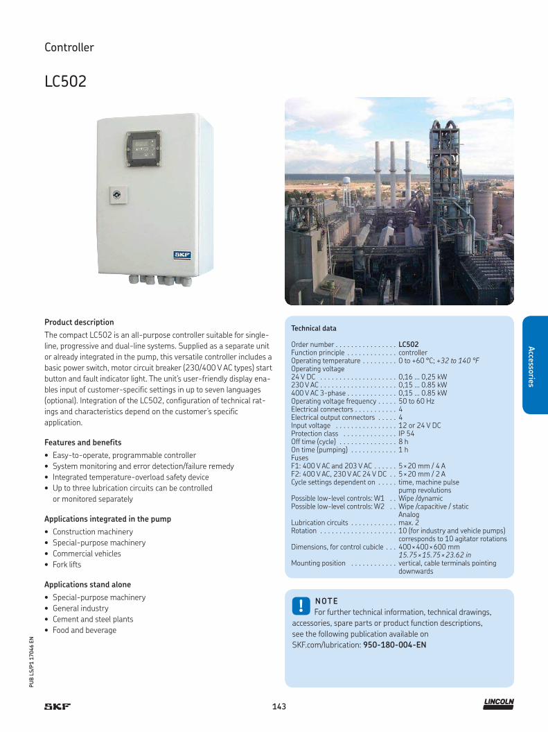
143
PU
B L
S/P
1 1
7046 E
N
Accesso
ries
Controller
LC502
!NOTE
For further technical information, technical drawings,
accessories, spare parts or product function descriptions,
see the following publication available on
SKF.com/lubrication: 950-180-004-EN
Technical data
Order number . . . . . . . . . . . . . . . . LC502Function principle . . . . . . . . . . . . . controllerOperating temperature . . . . . . . . . 0 to +60 °C; +32 to 140 °FOperating voltage 24 V DC . . . . . . . . . . . . . . . . . . . . 0,16 ... 0,25 kW230 V AC . . . . . . . . . . . . . . . . . . . . 0,15 ... 0.85 kW400 V AC 3-phase . . . . . . . . . . . . . 0,15 ... 0.85 kWOperating voltage frequency . . . . . 50 to 60 HzElectrical connectors . . . . . . . . . . . 4Electrical output connectors . . . . . 4Input voltage . . . . . . . . . . . . . . . . 12 or 24 V DCProtection class . . . . . . . . . . . . . . IP 54Off time (cycle) . . . . . . . . . . . . . . . 8 hOn time (pumping) . . . . . . . . . . . . 1 hFusesF1: 400 V AC and 203 V AC . . . . . . 5 × 20 mm / 4 AF2: 400 V AC, 230 V AC 24 V DC . . 5 × 20 mm / 2 ACycle settings dependent on . . . . . time, machine pulse
pump revolutionsPossible low-level controls: W1 . . Wipe /dynamic Possible low-level controls: W2 . . Wipe /capacitive / static
AnalogLubrication circuits . . . . . . . . . . . . max. 2Rotation . . . . . . . . . . . . . . . . . . . . 10 (for industry and vehicle pumps)
corresponds to 10 agitator rotationsDimensions, for control cubicle . . . 400 × 400 × 600 mm
15.75 × 15.75 × 23.62 inMounting position . . . . . . . . . . . . vertical, cable terminals pointing
downwards
Product description
The compact LC502 is an all-purpose controller suitable for single-
line, progressive and dual-line systems. Supplied as a separate unit
or already integrated in the pump, this versatile controller includes a
basic power switch, motor circuit breaker (230/400 V AC types) start
button and fault indicator light. The unit’s user-friendly display ena-
bles input of customer-specific settings in up to seven languages
(optional). Integration of the LC502, configuration of technical rat-
ings and characteristics depend on the customer’s specific
application.
Features and benefits
• Easy-to-operate, programmable controller
• System monitoring and error detection/failure remedy
• Integrated temperature-overload safety device
• Up to three lubrication circuits can be controlled
or monitored separately
Applications integrated in the pump
• Construction machinery
• Special-purpose machinery
• Commercial vehicles
• Fork lifts
Applications stand alone
• Special-purpose machinery
• General industry
• Cement and steel plants
• Food and beverage

144
PU
B L
S/P
1 1
7046 E
N
Acc
esso
ries
Controller
ST–1340 and ST–1440
Product description
SKF ST-1340 and ST-1440 CPUs are microprocessor-based
control centres for use in single-line lubrication systems, as well
as dual-line and progressive lubrication systems. Featuring an
alphanumeric keypad and display, the two units are identical with
the exception of case size and maximum number of lubrication
channels served. The ST–1340 controls up to four separate lubrica-
tion channels, while the ST–1440 controls up to 14 channels, each
having independent lubrication parameters and/or lubricants. The
lubrication system is expandable by installing new channel modules,
and configuration is determined in the field by the user. Pressure
switches and transmitters or piston detectors can be used in all
channels.
Features and benefits
• Versatile and durable
• Modular units provide easy system modification
• Automatic pump change (Dualset)
• Grease-spraying control with air monitoring
• Compatible with SKF Doser monitor
• Works with SKF Online 1440 control software
• Program status and lubrication history data
are protected by a back-up battery
ST–1340 and ST–1440
Order number Designation
VGEV 12380695 ST–1340 control centreVGEV 12501254 1 channel module
VGEV 12380700 ST–1440 control centreVGEV 12501254 4 channel module
Technical data
Function principle . . . . . . . . . . . control centreOperating temperature . . . . . . . 0 to +60 °C; +32 to +140 °FLubricant. . . . . . . . . . . . . . . . . . oil and greaseLubricant channels . . . . . . . . . . ST–1340: up to 4
ST–1440: up to 14Operating voltage . . . . . . . . . . . 93 to 132 V AC, 186 to 264 V ACOperating voltage frequency . . . 47 to 63 HzOperating current . . . . . . . . . . . 5,4 A/115 V AC, 2,2 A/ 230 V ACControl voltage . . . . . . . . . . . . . 24 V DC, ± 10%Overload protection . . . . . . . . . . automatic fuse, 6 ACable connection . . . . . . . . . . . . screw terminals for 2,5 mm2 wiresProtection class . . . . . . . . . . . . . IP 65Interface . . . . . . . . . . . . . . . . . . alphanumeric keypad and display,
4 × 20 characters, RS-422 Modbus port
Dimensions:ST-1340 . . . . . . . . . . . . . . . . . .
600 × 380 × 210 mm23.6 × 14.9 × 8.3 in
ST-1440 . . . . . . . . . . . . . . . . . . 600 × 600 × 210 mm23.6 × 23.6 × 8.3 in
Options . . . . . . . . . . . . . . . . . . . SMS control featureOff time (cycle). . . . . . . . . . . . . .On time (pumping) . . . . . . . . . .Mounting positions . . . . . . . . . .
1 min to 999 h 59 min0 s to 9 999 svertical
!NOTE
For further technical information, technical drawings,
accessories, spare parts or product function descriptions, see
the following publication available on SKF.com/lubrication:
PUB LS/P8 13166 EN
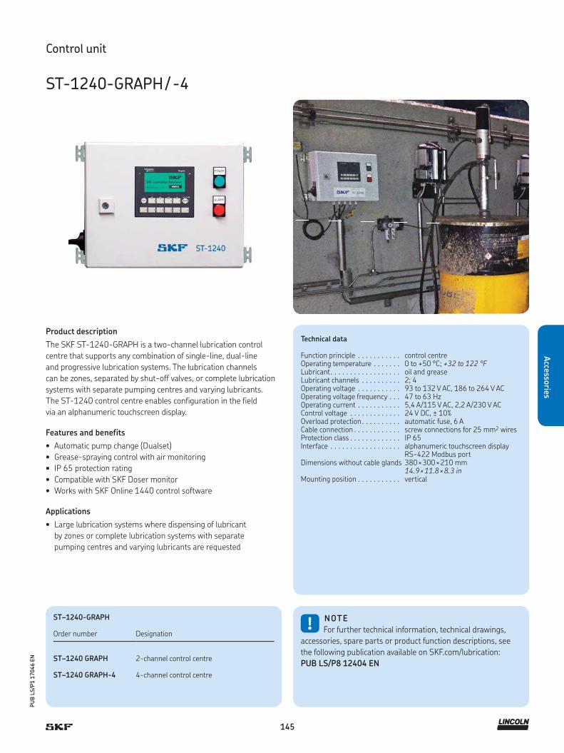
145
PU
B L
S/P
1 1
7046 E
N
Accesso
ries
Product description
The SKF ST-1240-GRAPH is a two-channel lubrication control
centre that supports any combination of single-line, dual-line
and progressive lubrication systems. The lubrication channels
can be zones, separated by shut-off valves, or complete lubrication
systems with separate pumping centres and varying lubricants.
The ST-1240 control centre enables configuration in the field
via an alphanumeric touchscreen display.
Features and benefits
• Automatic pump change (Dualset)
• Grease-spraying control with air monitoring
• IP 65 protection rating
• Compatible with SKF Doser monitor
• Works with SKF Online 1440 control software
Applications
• Large lubrication systems where dispensing of lubricant
by zones or complete lubrication systems with separate
pumping centres and varying lubricants are requested
ST–1240-GRAPH
Order number Designation
ST–1240 GRAPH 2-channel control centre
ST–1240 GRAPH-4 4-channel control centre
Control unit
ST-1240-GRAPH / -4
Technical data
Function principle . . . . . . . . . . . control centreOperating temperature . . . . . . . 0 to +50 °C; +32 to 122 °FLubricant. . . . . . . . . . . . . . . . . . oil and greaseLubricant channels . . . . . . . . . . 2; 4Operating voltage . . . . . . . . . . . 93 to 132 V AC, 186 to 264 V ACOperating voltage frequency . . . 47 to 63 HzOperating current . . . . . . . . . . . 5,4 A/115 V AC, 2,2 A/230 V ACControl voltage . . . . . . . . . . . . . 24 V DC, ± 10%Overload protection . . . . . . . . . . automatic fuse, 6 ACable connection . . . . . . . . . . . . screw connections for 25 mm2 wiresProtection class . . . . . . . . . . . . . IP 65Interface . . . . . . . . . . . . . . . . . . alphanumeric touchscreen display
RS-422 Modbus portDimensions without cable glands 380 × 300 × 210 mm
14.9 × 11.8 × 8.3 inMounting position . . . . . . . . . . . vertical
!NOTE
For further technical information, technical drawings,
accessories, spare parts or product function descriptions, see
the following publication available on SKF.com/lubrication:
PUB LS/P8 12404 EN
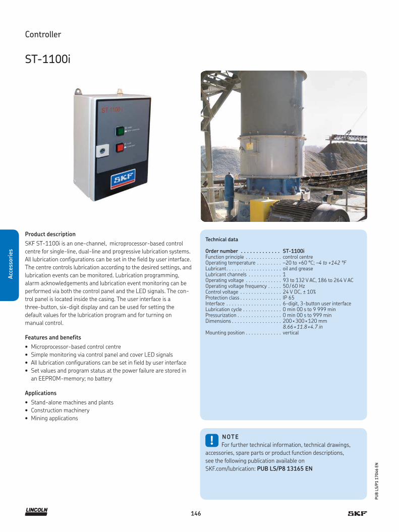
146
PU
B L
S/P
1 1
7046 E
N
Acc
esso
ries
Technical data
Order number . . . . . . . . . . . . . ST-1100iFunction principle . . . . . . . . . . . . . control centreOperating temperature . . . . . . . . . –20 to +60 °C; –4 to +142 °FLubricant. . . . . . . . . . . . . . . . . . . . Lubricant channels . . . . . . . . . . . .
oil and grease1
Operating voltage . . . . . . . . . . . . . 93 to 132 V AC, 186 to 264 V ACOperating voltage frequency . . . . . 50 / 60 HzControl voltage . . . . . . . . . . . . . . . 24 V DC, ± 10%Protection class . . . . . . . . . . . . . . . IP 65Interface . . . . . . . . . . . . . . . . . . . . 6-digit, 3-button user interfaceLubrication cycle . . . . . . . . . . . . . . 0 min 00 s to 9 999 minPressurization . . . . . . . . . . . . . . . . 0 min 00 s to 999 minDimensions . . . . . . . . . . . . . . . . . . 200 × 300 × 120 mm
8.66 × 11.8 × 4.7 inMounting position . . . . . . . . . . . . . vertical
Controller
ST-1100i
Product description
SKF ST-1100i is an one-channel, microprocessor-based control
centre for single-line, dual-line and progressive lubrication systems.
All lubrication configurations can be set in the field by user interface.
The centre controls lubrication according to the desired settings, and
lubrication events can be monitored. Lubrication programming,
alarm acknowledgements and lubrication event monitoring can be
performed via both the control panel and the LED signals. The con-
trol panel is located inside the casing. The user interface is a
three-button, six-digit display and can be used for setting the
default values for the lubrication program and for turning on
manual control.
Features and benefits
• Microprocessor-based control centre
• Simple monitoring via control panel and cover LED signals
• All lubrication configurations can be set in field by user interface
• Set values and program status at the power failure are stored in
an EEPROM-memory; no battery
Applications
• Stand-alone machines and plants
• Construction machinery
• Mining applications
!NOTE
For further technical information, technical drawings,
accessories, spare parts or product function descriptions,
see the following publication available on
SKF.com/lubrication: PUB LS/P8 13165 EN

147
PU
B L
S/P
1 1
7046 E
N
Accesso
ries
Controller
ST-102
Product description
The ST-102 controller is designed for the control and monitoring
of single-line, dual-line and progressive lubrication systems in
vehicles with a 12 or 24 V DC power supply. It is a one-channel
lubrication control centre for systems with pneumatic or electrical
pumps. The ST-102 is suitable for environments with temperatures
ranging from -40 to +80 °C (-40 to +176 °F) and features an IP 40
protection class. All lubrication configurations can be set in the field
by the user.
Features and benefits
• Available for 12 or 24V DC
• Suitable for operational environments
with extreme temperatures
• One-button user interface
• Power failure memory
Applications
• Vehicles
• Construction machinery
• Agriculture
ST–102
Order number Designation
11500607 V1 for progressive and single-line systems
11500610 V2 for progressive, dual- and single-line systems
Technical data
Function principle . . . . . . . . . . . . control and monitoring deviceOperating temperature . . . . . . . . -40 to +80 °C; -40 to +176 °FPower supply. . . . . . . . . . . . . . . . 12 and 24 V DC; (10,5 to 32 V DC)Pump output control . . . . . . . . . . max. 5 AProtection class . . . . . . . . . . . . . IP 30Self-setting fuse . . . . . . . . . . . . . 4 A on pcbTime, cycle settings:Max. pressurization time . . . . . . . 1 to 20 minInterval time . . . . . . . . . . . . . . . . 5, 10…120 minPressurization time . . . . . . . . . . . 1,2,3…10 minInterface . . . . . . . . . . . . . . . . . . . 1-button user interface, 3 LED’sInput . . . . . . . . . . . . . . . . . . . . . . 4 digitalOutput. . . . . . . . . . . . . . . . . . . . . 4 digitalStandard . . . . . . . . . . . . . . . . . . . CEDimensions . . . . . . . . . . . . . . . . . 26 × 60 × 160 mm
1.02 × 2.36 × 6.3 inMounting position . . . . . . . . . . . . vertical
!NOTE
For further technical information, technical drawings,
accessories, spare parts or product function descriptions,
see the following publication available on SKF.com/lubrication:
6408 EN

148
PU
B L
S/P
1 1
7046 E
N
Acc
esso
ries
Controller
ST-102P
Product description
The ST-102P one-channel lubrication control centre is designed for
the control and monitoring of lubrication systems in 12V DC or 24V
DC vehicles. It supports single-line and dual-line lubrication sys-
tems. All lubrication configurations can be set in the field by the user.
The ST-102P casing has an IP 65 rating.
Features and benefits
• Designed for control and monitoring in
12/24 V DC lubrication systems
• Reliable and durable, one-channel lubrication controller
• Supports single-line and dual-line lubrication systems
• All lubrication configurations can be set in the field by user
• IP 65 rating
Applications
• Control of lubrication systems with pneumatic pump
SKF 40PGAS and electrical pump SKF Minilube
• Small excavators
• Wheel loaders
• Delivery trucks
• Buses, vehicles
!NOTE
For further technical information, technical drawings,
accessories, spare parts or product function descriptions,
see the following publication available on
SKF.com/lubrication: 13165 EN
Technical data
Order number . . . . . . . . . . . . . . . . ST-102PFunction principle . . . . . . . . . . . . . controllerOperating temperature . . . . . . . . . –40 to +80 °C
–40 to +176 °FOperating voltage . . . . . . . . . . . . . 12 or 24 V DC, (10,5 to 32 V DC)Pump output control . . . . . . . . . . . max. 5 AProtection class . . . . . . . . . . . . . . IP 65 Self-setting fuse . . . . . . . . . . . . . . 4 A on printed circuit boardTime, cycle settings:Pressurization time . . . . . . . . . . . . 1 to 20 minInterval time . . . . . . . . . . . . . . . . . 5, 10…120 minInterface . . . . . . . . . . . . . . . . . . . . 1-button user interface, 3 LEDsDimensions . . . . . . . . . . . . . . . . . 67 × 80 × 170 mm
2.64 × 3.14 × 6.7 inMounting position . . . . . . . . . . . . . vertical
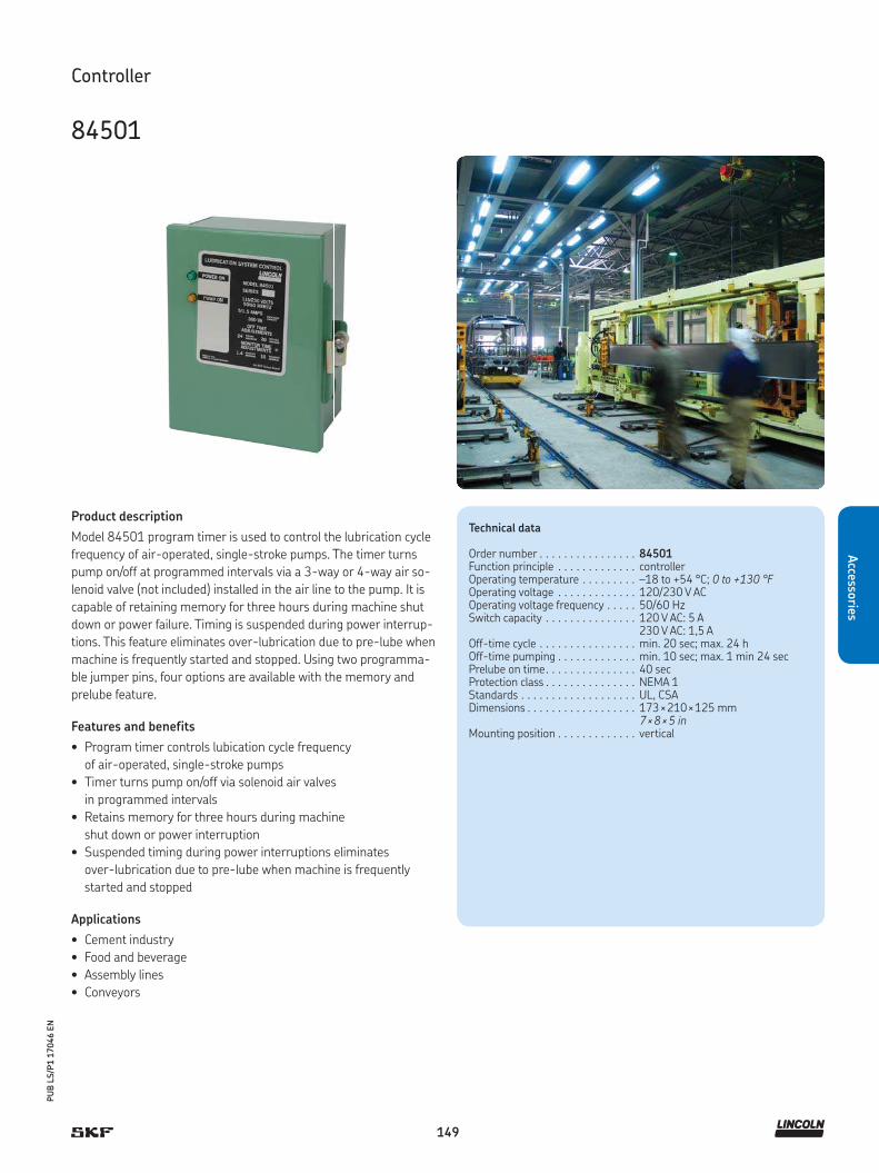
149
PU
B L
S/P
1 1
7046 E
N
Accesso
ries
Controller
84501
Product description
Model 84501 program timer is used to control the lubrication cycle
frequency of air-operated, single-stroke pumps. The timer turns
pump on/off at programmed intervals via a 3-way or 4-way air so-
lenoid valve (not included) installed in the air line to the pump. It is
capable of retaining memory for three hours during machine shut
down or power failure. Timing is suspended during power interrup-
tions. This feature eliminates over-lubrication due to pre-lube when
machine is frequently started and stopped. Using two programma-
ble jumper pins, four options are available with the memory and
prelube feature.
Features and benefits
• Program timer controls lubication cycle frequency
of air-operated, single-stroke pumps
• Timer turns pump on/off via solenoid air valves
in programmed intervals
• Retains memory for three hours during machine
shut down or power interruption
• Suspended timing during power interruptions eliminates
over-lubrication due to pre-lube when machine is frequently
started and stopped
Applications
• Cement industry
• Food and beverage
• Assembly lines
• Conveyors
Technical data
Order number . . . . . . . . . . . . . . . . 84501Function principle . . . . . . . . . . . . . controllerOperating temperature . . . . . . . . . –18 to +54 °C; 0 to +130 °FOperating voltage . . . . . . . . . . . . . 120/230 V ACOperating voltage frequency . . . . . 50/60 HzSwitch capacity . . . . . . . . . . . . . . . 120 V AC: 5 A
230 V AC: 1,5 AOff-time cycle . . . . . . . . . . . . . . . . min. 20 sec; max. 24 hOff-time pumping . . . . . . . . . . . . . min. 10 sec; max. 1 min 24 secPrelube on time. . . . . . . . . . . . . . . 40 secProtection class . . . . . . . . . . . . . . . NEMA 1Standards . . . . . . . . . . . . . . . . . . . UL, CSADimensions . . . . . . . . . . . . . . . . . . 173 × 210 × 125 mm
7 × 8 × 5 in Mounting position . . . . . . . . . . . . . vertical

150
PU
B L
S/P
1 1
7046 E
N
Acc
esso
ries
Product description
Model 84015 is a 12/24 V DC-powered, solid-state controller for
lubrication systems. It is microprocessor-based and can be used
for automatic lubrication systems on mobile equipment or where
AC power is not available. Its rugged construction with liquid- and
dust-tight enclosure includes a manual push-button for remote
initiation of a lubrication cycle. The controller always will start with
an “off-time” period.
Features and benefits
• 12/24 V DC-powered, solid-state controller
• Microprocessor-based
• For automatic lubrication systems on mobile equipment
• Rugged construction with liquid- and dust-tight enclosure
Applications
• Construction machinery
• Delivery trucks
• Buses, vehicles
Controller
84015
Technical data
Order number . . . . . . . . . . . . . . . . 84015Function principle . . . . . . . . . . . . . controllerOperating temperature . . . . . . . . . –18 to +55 °C; 0 to +131 °FOperating voltage . . . . . . . . . . . . . 24 V DC, (10-30 V DC) Operating current . . . . . . . . . . . . . 25 mA 1)
Switch capacity . . . . . . . . . . . . . . . 5 AOff-time cycle . . . . . . . . . . . . . . . . min. 2,5 min; max. 80 minOff-time pumping . . . . . . . . . . . . . fixed: 75 secProtection class . . . . . . . . . . . . . . . NEMA 12Off-time (cycle) 2). . . . . . . . . . . . . . min. 90 sec
max. 80 minOn-time (pumping) . . . . . . . . . . . . fixed, 75 secDimensions . . . . . . . . . . . . . . . . . . 79 × 133 × 76 mm
3.1 × 5.2 × 3 in Mounting position . . . . . . . . . . . . . vertical or horizontal
1) Less load2) Available selections are 2.5, 5, 10, 20, 40 or 80 min
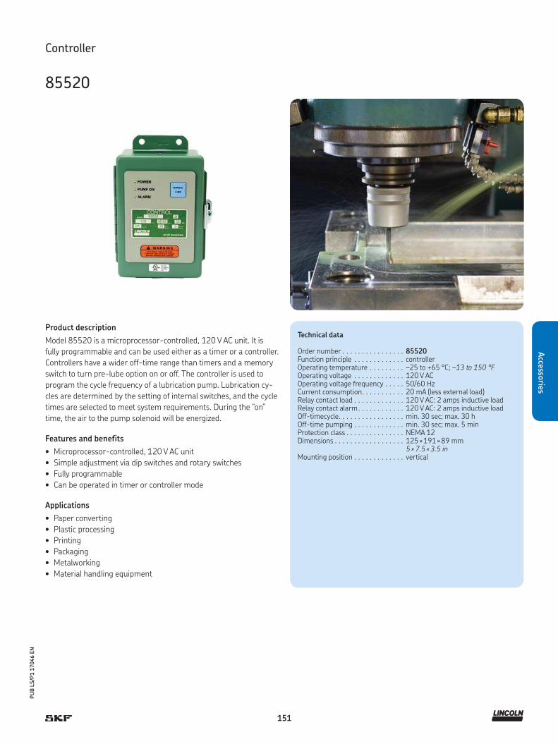
151
PU
B L
S/P
1 1
7046 E
N
Accesso
ries
Controller
85520
Product description
Model 85520 is a microprocessor-controlled, 120 V AC unit. It is
fully programmable and can be used either as a timer or a controller.
Controllers have a wider off-time range than timers and a memory
switch to turn pre-lube option on or off. The controller is used to
program the cycle frequency of a lubrication pump. Lubrication cy-
cles are determined by the setting of internal switches, and the cycle
times are selected to meet system requirements. During the “on”
time, the air to the pump solenoid will be energized.
Features and benefits
• Microprocessor-controlled, 120 V AC unit
• Simple adjustment via dip switches and rotary switches
• Fully programmable
• Can be operated in timer or controller mode
Applications
• Paper converting
• Plastic processing
• Printing
• Packaging
• Metalworking
• Material handling equipment
Technical data
Order number . . . . . . . . . . . . . . . . 85520Function principle . . . . . . . . . . . . . controllerOperating temperature . . . . . . . . . –25 to +65 °C; –13 to 150 °FOperating voltage . . . . . . . . . . . . . 120 V ACOperating voltage frequency . . . . . 50/60 HzCurrent consumption. . . . . . . . . . . 20 mA (less external load)Relay contact load . . . . . . . . . . . . . 120 V AC: 2 amps inductive load Relay contact alarm. . . . . . . . . . . . 120 V AC: 2 amps inductive load Off-timecycle. . . . . . . . . . . . . . . . . min. 30 sec; max. 30 hOff-time pumping . . . . . . . . . . . . . min. 30 sec; max. 5 minProtection class . . . . . . . . . . . . . . . NEMA 12Dimensions . . . . . . . . . . . . . . . . . . 125 × 191 × 89 mm
5 × 7.5 × 3.5 in Mounting position . . . . . . . . . . . . . vertical

152
PU
B L
S/P
1 1
7046 E
N
Acc
esso
ries
Technical data
Order number . . . . . . . . . . . . . . . . 85535Function principle . . . . . . . . . . . . . controllerOperating temperature . . . . . . . . . -40 to +65 °C; -40 to 150 °FOperating voltage . . . . . . . . . . . . . 24 V DC; (21 to 30 V DC)Operating voltage frequency . . . . . 50/60 HzCurrent consumption. . . . . . . . . . . 100 mA (less external load)Relay contact load . . . . . . . . . . . . . 30 V DC: 2 amps inductive loadExternal alarm load . . . . . . . . . . . . 30 V DC: 2 amps inductive loadOff-time cycle . . . . . . . . . . . . . . . . min. 30 sec; max. 30 hOn-time pumping . . . . . . . . . . . . . min. 30 sec; max. 120 secProtection class . . . . . . . . . . . . . . . NEMA 12Dimensions . . . . . . . . . . . . . . . . . . 125 × 191 × 89 mm
5 × 7.5 × 3.5 inMounting position . . . . . . . . . . . . . vertical
Controller
85535
Product description
Model 85535 is a microprocessor-controlled, 24 V DC unit. It is fully
programmable and can be used either as a timer or a controller.
Controllers have a wider off-time range than timers and a memory
switch to turn pre-lube option on or off. The controller is used to
program the cycle frequency of a lubrication pump. Lube cycles are
determined by the setting of internal switches, and the cycle times
are selected to meet system requirements. During the “on” time, the
air to the pump solenoid will be energized.
Features and benefits
• Microprocessor-controlled, 24 V DC unit
• Simple adjustment via dip switches and rotary switches
• Fully programmable
• Can be operated in timer or controller mode
Applications
• Paper converting
• Plastic processing
• Printing
• Packaging
• Metalworking
• Material handling equipment

153
PU
B L
S/P
1 1
7046 E
N
Accesso
ries
Technical data
Order number . . . . . . . . . . . . . . . . 85530Function principle . . . . . . . . . . . . . controllerOperating temperature . . . . . . . . . 0 to +50 °C; +32 to 122 °FOperating voltage . . . . . . . . . . . . . 24 V DC, 120 and 230 V ACOperating voltage frequency . . . . . 50/60 HzOperating current (less load) . . . . . 24 V DC: 250 mA
120 V DC: 85 mA230 V DC: 45 mA
External pump load . . . . . . . . . . . . 360 VA pilot duty rating at 120/230 V AC
External alarm load . . . . . . . . . . . . 24 V DC: 5 AAmpacity to terminal strip B . . . . . 15 V DC: 8 mAOff-time cycle . . . . . . . . . . . . . . . . min. 1 min; max. 9 900 minAlarm time . . . . . . . . . . . . . . . . . . min. 1 min; max. 99 minTiming accuracy . . . . . . . . . . . . . . 0,01% (crystal controlled)Off-time counts . . . . . . . . . . . . . . . min. 1 min; max. 9 900 countsCount rate . . . . . . . . . . . . . . . . . . . 30 counts/sec at 50% duty cycleProtection class . . . . . . . . . . . . . . . NEMA 12 enclosureDimensions . . . . . . . . . . . . . . . . . . 227 × 241 × 105 mm
9 × 9.5 × 4 inMounting position . . . . . . . . . . . . . vertical
Controller
85530
Product description
Model 85530 will have complete control of your lubrication system.
The system status is continuously updated and displayed on a two-
line, liquid crystal display. Due to the numerous options available,
the customer can program the controller to match system require-
ments in the field. Programming is accomplished easily by following
a user-friendly menu displayed on the LCD and pressing the active
buttons beneath the display. An internal jumper pin provides security
against unauthorized programming. All programmed parameters
are stored automatically in a non-volatile memory. A review screen
can be activated to display what has been programmed, and these
can be changed whenever necessary. Three lights on the enclosure
door indicate system status.
Features and benefits
• Simple programming via user-friendly
menu on LCD and active buttons
• Security against unauthorized programming
via an internal jumper pin
• All programmed parameters are stored
automatically in a non-volatile memory
• Programmed parameters can be reviewed easily
• Programmed values can be changed whenever necessary
• Three lights indicate system status
Applications
• Paper converting
• Plastic processing
• Printing
• Packaging
• Metalworking
• Material handling equipment

154
PU
B L
S/P
1 1
7046 E
N
Acc
esso
ries
Technical data
Order number . . . . . . . . . . . . . . . . LMC 101Function principle . . . . . . . . . . . . . control unitIVoltage input . . . . . . . . . . . . . . . . 12 V DC and 24 V DC -20%/ +30%Current consumption. . . . . . . . . . . 60 mA (less external load)Vent relay contact . . . . . . . . . . . . . 20 A at 30 V DCPump relay contact . . . . . . . . . . . . 2 A at 30 V DCAlarm relay contact . . . . . . . . . . . . 2 A at 30 V DCEnclosure rating . . . . . . . . . . . . . . NEMA 12Operating temperature . . . . . . . . . –40 to +65 °C; –40 to +150 °FNet weight. . . . . . . . . . . . . . . . . . . 0,9 kg, 2 lbsOff-time adjustable . . . . . . . . . . . . 15 sec to 99 hOn-time adjustable . . . . . . . . . . . . 15 sec to 99 hLubrication systems. . . . . . . . . . . . single-line and progressive systemsEnclosure size . . . . . . . . . . . . . . . . 209 × 127 × 89 mm
8.25 × 5 × 3.50 inMounting dimensions . . . . . . . . . . 222 × 95 mm
8.75 × 3.75 in
Controller
LMC 101
Product description
LMC 101 is a universal control and monitoring device for single-line
and progressive lubrication systems. In single-line systems, pressure
switches or pressure transducers can be installed at the pump and/
or end of the supply line. While designed for off-the-road and mo-
bile equipment use, the controller can be used for any low-voltage
lubrication application. Timer or controller mode can be set for both
systems. The device features various alarm condition settings, in-
cluding cycle frequency or alarm triggers. Programming, data log-
ging and reporting are possible, including system resets, downloads
to controllers, lubrication activity, lubrication cycles and alarms. The
controller must be programmed via USB connection to PC. In timer
mode, the lubrication cycle ends when pre-assigned time has ex-
pired. In controller mode, the lubrication cycle ends when pressure
switch, pressure transducer or piston detector actuates. System al-
lows pressure to dissipate to end of supply line once pressure at
pump is reached.
Features and benefits
• Various alarm condition settings including cycle
frequency and alarm triggers
• Programming, data logging and reporting, including
system resets, downloads to controllers, lubrication activity,
lubrication cycles and alarms
• Display: LEDs, pump on and system fault (alarm)
• Controller must be programmed via USB connection to PC
• Manual lubrication push-button
Applications
• Off-highway vehicles
• Mobile equipment use
!NOTE
For further technical information, technical drawings,
accessories, spare parts or product function descriptions,
see the following publication available on
SKF.com/lubrication: 15625 EN
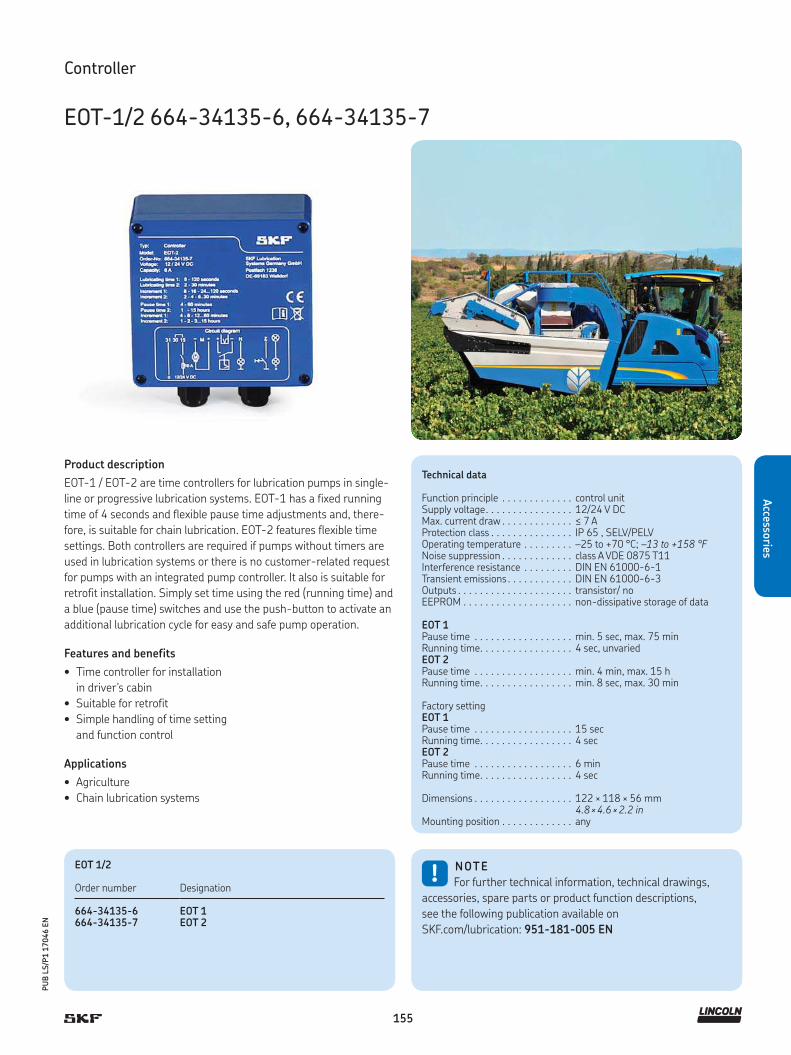
155
PU
B L
S/P
1 1
7046 E
N
Accesso
ries
Technical data
Function principle . . . . . . . . . . . . . control unitSupply voltage. . . . . . . . . . . . . . . . 12/24 V DCMax. current draw . . . . . . . . . . . . . ≤ 7 AProtection class . . . . . . . . . . . . . . . IP 65 , SELV/PELVOperating temperature . . . . . . . . . –25 to +70 °C; –13 to +158 °F Noise suppression . . . . . . . . . . . . . class A VDE 0875 T11Interference resistance . . . . . . . . . DIN EN 61000-6-1Transient emissions . . . . . . . . . . . . DIN EN 61000-6-3 Outputs . . . . . . . . . . . . . . . . . . . . . transistor/ noEEPROM . . . . . . . . . . . . . . . . . . . . non-dissipative storage of data
EOT 1Pause time . . . . . . . . . . . . . . . . . . min. 5 sec, max. 75 min Running time. . . . . . . . . . . . . . . . . 4 sec, unvariedEOT 2Pause time . . . . . . . . . . . . . . . . . . min. 4 min, max. 15 h Running time. . . . . . . . . . . . . . . . . min. 8 sec, max. 30 min
Factory settingEOT 1Pause time . . . . . . . . . . . . . . . . . . 15 secRunning time. . . . . . . . . . . . . . . . . 4 secEOT 2Pause time . . . . . . . . . . . . . . . . . . 6 min Running time. . . . . . . . . . . . . . . . . 4 sec
Dimensions . . . . . . . . . . . . . . . . . . 122 × 118 × 56 mm 4.8 × 4.6 × 2.2 in
Mounting position . . . . . . . . . . . . . any
Controller
EOT-1/2 664-34135-6, 664-34135-7
Product description
EOT-1 / EOT-2 are time controllers for lubrication pumps in single-
line or progressive lubrication systems. EOT-1 has a fixed running
time of 4 seconds and flexible pause time adjustments and, there-
fore, is suitable for chain lubrication. EOT-2 features flexible time
settings. Both controllers are required if pumps without timers are
used in lubrication systems or there is no customer-related request
for pumps with an integrated pump controller. It also is suitable for
retrofit installation. Simply set time using the red (running time) and
a blue (pause time) switches and use the push-button to activate an
additional lubrication cycle for easy and safe pump operation.
Features and benefits
• Time controller for installation
in driver's cabin
• Suitable for retrofit
• Simple handling of time setting
and function control
Applications
• Agriculture
• Chain lubrication systems
!NOTE
For further technical information, technical drawings,
accessories, spare parts or product function descriptions,
see the following publication available on
SKF.com/lubrication: 951-181-005 EN
EOT 1/2
Order number Designation
664-34135-6 EOT 1664-34135-7 EOT 2

156
PU
B L
S/P
1 1
7046 E
N
Acc
esso
ries
Product description
The LMC 301 is a compact, modularly expandable control and
monitoring device. The device is equipped with an LCD display and
six functional keys for programming, parameter setting and signali-
zation. The user is guided through the setting menu. Also, there is a
simple-to-use PC software for parameter setting and diagnostics
available.
Features and benefits
• Integrated, flexible lubrication programs
• Basic device with 10 digital inputs, of which two
can be used analogously, and eight outputs
• Up to seven extension modules can be added, whereby each
module has 10 E 8 A just like the basic device
• Three lubrication pumps can be controlled and monitored,
each of which provides up to three lubrication circuits
• Single modules are connected by a bus interface
Applications
• Cement ans steel industry
• Mining; stationary and mobile excavators
• Food and beverage
Technical data
Function principle . . . . . . . . . . . . . electronic controllerOperating temperature V AC . . . . . –10 to +50 °C; +14 to +122 °FOperating temperature V DC . . . . . –40 to +70 °C; –40 to +158 °FInputs . . . . . . . . . . . . . . . . . . . . . . 10 count, short-ciruitOutputs . . . . . . . . . . . . . . . . . . . . . 8 counts, relay outputs NO-contact
8 A, 2 of which up to 20 ASupply voltage depending on model . . . . . . . . . . . 90-264 V AC, 24 V DC ± 20% Protection class . . . . . . . . . . . . . . . IP 64Dimensions . . . . . . . . . . . . . . . . . . 270 × 170 × 90 mm
10.7 × 6.7 × 3.5 inMounting position . . . . . . . . . . . . . vertical
Controller
LMC 301
!NOTE
For further technical information, technical drawings,
accessories, spare parts or product function descriptions,
see the following publication available on
SKF.com/lubrication: 15967 EN
LMC 301
Order number Designation
86500 LMC 301 230 AC (230 V AC)86501 LMC 301 24 DC (24 V DC)
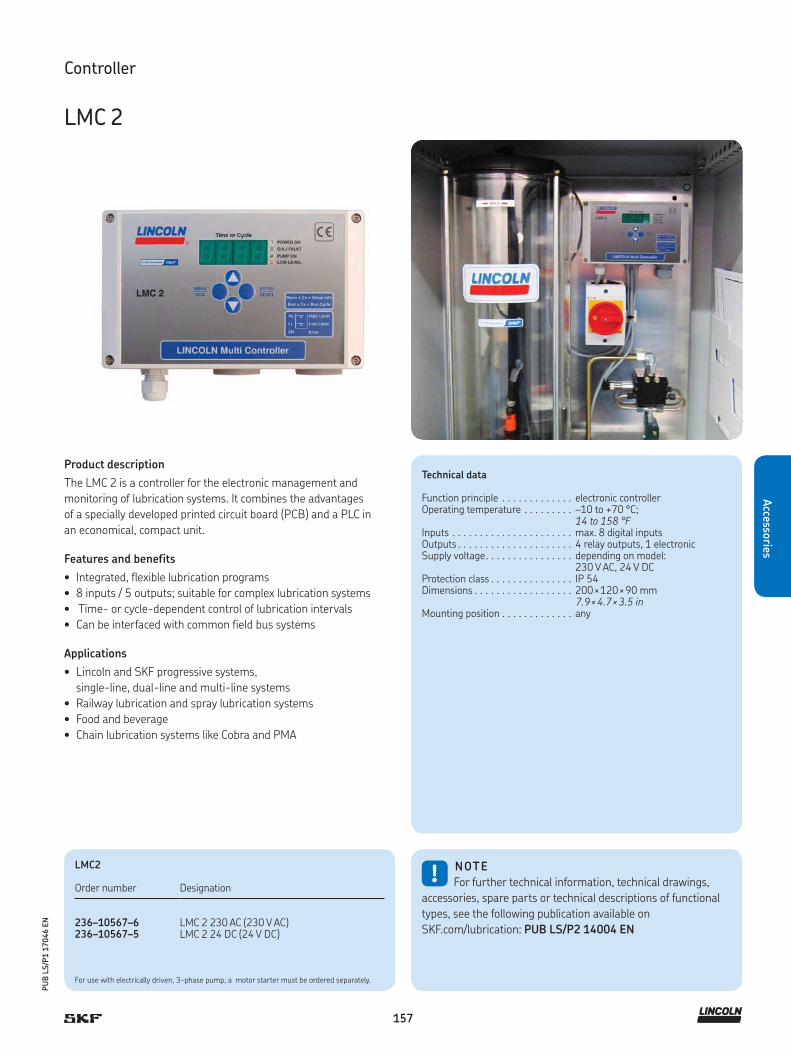
157
PU
B L
S/P
1 1
7046 E
N
Accesso
ries
Product description
The LMC 2 is a controller for the electronic management and
monitoring of lubrication systems. It combines the advantages
of a specially developed printed circuit board (PCB) and a PLC in
an economical, compact unit.
Features and benefits
• Integrated, flexible lubrication programs
• 8 inputs / 5 outputs; suitable for complex lubrication systems
• Time- or cycle-dependent control of lubrication intervals
• Can be interfaced with common field bus systems
Applications
• Lincoln and SKF progressive systems,
single-line, dual-line and multi-line systems
• Railway lubrication and spray lubrication systems
• Food and beverage
• Chain lubrication systems like Cobra and PMA
LMC2
Order number Designation
236–10567–6 LMC 2 230 AC (230 V AC)236–10567–5 LMC 2 24 DC (24 V DC)
!NOTE
For further technical information, technical drawings,
accessories, spare parts or technical descriptions of functional
types, see the following publication available on
SKF.com/lubrication: PUB LS/P2 14004 EN
For use with electrically driven, 3-phase pump, a motor starter must be ordered separately.
Controller
LMC 2
Technical data
Function principle . . . . . . . . . . . . . electronic controllerOperating temperature . . . . . . . . . –10 to +70 °C;
14 to 158 °FInputs . . . . . . . . . . . . . . . . . . . . . . max. 8 digital inputsOutputs . . . . . . . . . . . . . . . . . . . . . 4 relay outputs, 1 electronicSupply voltage. . . . . . . . . . . . . . . . depending on model:
230 V AC, 24 V DCProtection class . . . . . . . . . . . . . . . IP 54Dimensions . . . . . . . . . . . . . . . . . . 200 × 120 × 90 mm
7.9 × 4.7 × 3.5 inMounting position . . . . . . . . . . . . . any

158
PU
B L
S/P
1 1
7046 E
N
Acc
esso
ries
Product description
Model 85525 is a microprocessor-controlled, 120 V AC unit
that includes a pressure switch and mounting brackets. It is fully
programmable and can be used either as a timer or a controller.
Controllers have a wider off-time range than timers and a memory
switch to turn pre-lube option on or off. The controller is used to
program the cycle frequency of a lubrication pump. Lubrication
cycles are determined by the setting of internal switches, and the
cycle times are selected to meet system requirements. During the
“on” time, the air to the pump solenoid will be energized. The en-
closed pressure switch senses supply line pressure rise/fall to
signal system operation to controller or system alarm.
Features and benefits
• Microprocessor-controlled, 120 V AC unit
• Includes pressure switch and brackets
• Simple setting via dip switches and rotary switches
• Fully programmable
• Can be operated in timer or controller mode
Applications
• Paper converting
• Plastic processing
• Printing
• Packaging
• Metalworking
• Material handling equipment
Controller kit
85525
Technical data
Order number . . . . . . . . . . . . . . . . 85525Function principle . . . . . . . . . . . . . control unitOperating temperature . . . . . . . . . –25 to +65 °C; –13 to 150 °FOperating voltage . . . . . . . . . . . . . 120 V ACOperating voltage frequency . . . . . 50/60 HzOperating current . . . . . . . . . . . . . 20 mA (less external load)Relay contact load . . . . . . . . . . . . . 2 amps inductive load at 120 V ACRelay contact alarm . . . . . . . . . . . 2 amps inductive load at 120 V ACOff-time (cycle) . . . . . . . . . . . . . . . min. 30 s, max. 30 hOn-time (pumping) . . . . . . . . . . . . min. 30 s, max. 5 minProtection class . . . . . . . . . . . . . . . NEMA 12 Dimensions . . . . . . . . . . . . . . . . . . 125 × 191 × 89 mm, 5 × 7.5 × 3.5 inMounting position . . . . . . . . . . . . . vertical
Pressure switch . . . . . . . . . . . . . . . 69630
Protection class . . . . . . . . . . . . . . . housing and UL-listed switching elements: NEMA 3
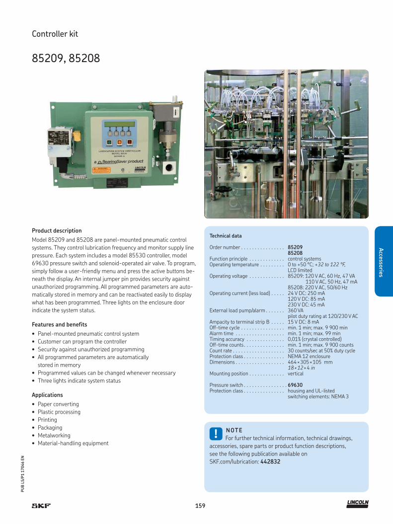
159
PU
B L
S/P
1 1
7046 E
N
Accesso
ries
Technical data
Order number . . . . . . . . . . . . . . . . 8520985208
Function principle . . . . . . . . . . . . . control systemsOperating temperature . . . . . . . . . 0 to +50 °C; +32 to 122 °F,
LCD limitedOperating voltage . . . . . . . . . . . . . 85209: 120 V AC, 60 Hz, 47 VA
110 V AC, 50 Hz, 47 mA85208: 220 V AC, 50/60 Hz
Operating current (less load) . . . . . 24 V DC: 250 mA120 V DC: 85 mA230 V DC: 45 mA
External load pump/alarm . . . . . . . 360 VA pilot duty rating at 120/230 V AC
Ampacity to terminal strip B . . . . . 15 V DC: 8 mAOff-time cycle . . . . . . . . . . . . . . . . min. 1 min; max. 9 900 minAlarm time . . . . . . . . . . . . . . . . . . min. 1 min; max. 99 minTiming accuracy . . . . . . . . . . . . . . 0,01% (crystal controlled)Off-time counts . . . . . . . . . . . . . . . min. 1 min; max. 9 900 countsCount rate . . . . . . . . . . . . . . . . . . . 30 counts/sec at 50% duty cycleProtection class . . . . . . . . . . . . . . . NEMA 12 enclosureDimensions . . . . . . . . . . . . . . . . . . 464 × 305 × 105 mm
18 × 12 × 4 inMounting position . . . . . . . . . . . . . vertical
Pressure switch . . . . . . . . . . . . . . . . 69630Protection class . . . . . . . . . . . . . . . housing and UL-listed
switching elements: NEMA 3
Controller kit
85209, 85208
Product description
Model 85209 and 85208 are panel-mounted pneumatic control
systems. They control lubrication frequency and monitor supply line
pressure. Each system includes a model 85530 controller, model
69630 pressure switch and solenoid-operated air valve. To program,
simply follow a user-friendly menu and press the active buttons be-
neath the display. An internal jumper pin provides security against
unauthorized programming. All programmed parameters are auto-
matically stored in memory and can be reactivated easily to display
what has been programmed. Three lights on the enclosure door
indicate the system status.
Features and benefits
• Panel-mounted pneumatic control system
• Customer can program the controller
• Security against unauthorized programming
• All programmed parameters are automatically
stored in memory
• Programmed values can be changed whenever necessary
• Three lights indicate system status
Applications
• Paper converting
• Plastic processing
• Printing
• Packaging
• Metalworking
• Material-handling equipment!
NOTE
For further technical information, technical drawings,
accessories, spare parts or product function descriptions,
see the following publication available on
SKF.com/lubrication: 442832

160
PU
B L
S/P
1 1
7046 E
N
Acc
esso
ries
Hosse connection control
HCC
Product description
The hose connection control (HCC) is intended to monitor electrically
conductive, high-pressure lubrication hoses for line breakage. If
there is a fault in the main line or feed lines, the unit alerts the ma-
chine operator immediately. Operation of the HCC is not affected by
line lengths, ambient temperature, pressure differential or pressure
losses. Utilizing non-conductive lubricants or hydraulic fluids, this
monitoring system has an operating pressure of up to 300 bar
(4 350 psi) and can be used in temperatures ranging from
–40 to +70 °C (–40 to +158 °F).
Features and benefits
• Immediately detects hose ruptures
• Expandable at any time
• Easy retrofit in existing lubrication systems
• Monitors difficult-to-access hoses to lubrication points
• Common LED signal of all connected hoses on the display
Applications
• Construction and mining machines; cranes
• Wood-handling machines
• Forklifts, reach stackers and machines with
movable units or accessories
• Agriculture
Technical data
Function principle . . . . . . . . . . . control and monitoring device for hose connections
Operating temperature . . . . . . . Isolator:–50 to +70 °C; –58 to +158 °FController:–25 to +70 °C; –13 to +158 °FController storage:–40 to +70 °C; –40 to +158 °F
Power supply. . . . . . . . . . . . . . . 12/24 V DCMonitored hose per monitoring unit . . . . . . . . . . . . . max. 15 pieces at 12 V DC
max. 24 pieces at 24 V DCPositive ok signal . . . . . . . . . . . . 12/24 V PNPSignal cable to one cut-off connector . . . . . . . . 20 m; 65 ftSignal cable at cut-off . . . . . . . . approx. 150 mm; 5.90 inProtection class . . . . . . . . . . . . . IP 65Dimensions . . . . . . . . . . . . . . . . 100 × 85 × 40 mm
3.93 × 3.34 × 1.57 in
!NOTE
For further technical information, technical drawings,
accessories, spare parts or product function descriptions,
see the following publication available online
at SKF.com/lubrication: 13615 EN
HCC Hose connection control
Order number Designation
236-10986-1 HCC, evaluation unit236-10153-3 HCC, with cable 20 m532-34839-2 HCC, endlink HCC DN 8-10L-E
532-37731-1 basic kit consisting of above three parts
532-34839-6 HCC, endlink HCC DN 4-6L-E
532-34839-3 HCC, interlink HCC DN 8-10L-I
532-34839-5 HCC, Interlink HCC DN 4-6L-I

161
PU
B L
S/P
1 1
7046 E
N
Accesso
ries
Flow controller
Flow sensor
Product description
Flow sensors keep an eye on the flow of oil from a metering point to
the lubrication point, metering out a small amount of oil for only a
short period of time. They are suitable for intermittent, centralized
lubrication systems e. g. with piston metering devices, metering ele-
ments, injection oilers, oil and air centralized lubrication systems.
Features and benefits
• Provide simple control
• Monitor flow of lubricant from the metering point
to the lubrication point
• Meter out a small amount of oil for only
a short period of time
Applications
• Machine tools
• Automotive manufacturing
• Industrial assembly and automation
Technical data
Ordner number . . . . . . . . . . . . . . . . GS304PFunction principle . . . . . . . . . . . . . . flow sensorMeasuring principle . . . . . . . . . . . . calorimetricalLubricant1 ) . . . . . . . . . . . . . . . . . . . oil (10 to 2 000 mm²/s)Metering quantity . . . . . . . . . . . . . . 0,01 - 0,6 cm³/pulse
0.0006 - 0.03in³/pulseClock frequency2) . . . . . . . . . . . . . . max. 4 pulse/minOperating temperature . . . . . . . . . . 10 to 50 °C, 50 to 122 °FOperating pressure . . . . . . . . . . . . . max. 40 bar; 580 psiRated voltage . . . . . . . . . . . . . . . . . 24 V DCResidual ripple . . . . . . . . . . . . . . . . 10%Working range UA . . . . . . . . . . . . . . 18 to 30 V DCMax. power consumption IE . . . . . . 25 mAPulse output . . . . . . . . . . . . . . . . . . 3 sLoad current IA for GS300 . . . . . . . max. 10 mAfor GS304 . . . . . . . . . . . . . . . . . . . . max. 500 mA per outputOutput protection . . . . . . . . . . . . . . short-circuit protectionBuilt-in plug . . . . . . . . . . . . . . . . . . circular connector with
M12×1 screw plugFluid connection . . . . . . . . . . . . . . . M 8x1 mm, port tapped for
solderless Ø 4 mm tubeconnection
Dimensions . . . . . . . . . . . . . . . . . . . 95 × 50 × 20 mm3.74 × 1.96 × 0.78 in
Mounting position . . . . . . . . . . . . . . directly upstream of lubrication pointVibration resistance . . . . . . . . . . . . 20 g
(DIN / IEC 68-2-27, 10-2000 Hz)Impact resistance . . . . . . . . . . . . . . 50 g (DIN / IEC 68-2-27, 11 ms)
!NOTE
For further technical information, technical drawings,
accessories, spare parts or product function descriptions,
see the following publication available on
SKF.com/lubrication: 1-1704-EN
1) Sensor needs 30 sec. of warm-up time2) The use of oils containing corrosive and/or abrasive additives may impair
sensor function and possibly damage the sensor

162
PU
B L
S/P
1 1
7046 E
N
Acc
esso
ries
Acc
esso
ries
Acc
esso
ries
Acc
esso
ries
Accessories for single-line lubrication systems
Pressure sensors
234-10825-8
DSA 247333
69630 234-10663-1
DSC1DSB1 DSC3
DSD 234-10330-4234-13161-5/9234-11145-3/4/5/9
DSC2
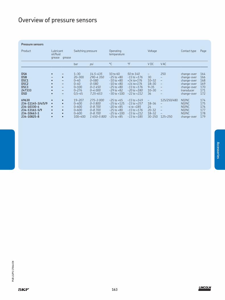
163
PU
B L
S/P
1 1
7046 E
N
Accesso
ries
Overview of pressure sensors
Pressure sensors
Product Lubricant Switching pressure Operating temparature
Voltage Contact type Pageoil/fluidgrease grease
bar psi °C °F V DC V AC
DSA • – 1–30 14.5–435 10 to 60 50 to 140 – 250 change-over 164DSB – • 20–300 290–4 350 -25 to +80 -13 to +176 30 – change-over 166DSC1 • – 0–40 0–580 -10 to +80 +14 to+176 10–32 – change-over 168DSC2 • – 0–40 0–580 -10 to +80 +14 to+176 18–30 – change-over 169DSC3 • – 0–100 0–1 450 -25 to +80 -13 to +176 9–35 – change-over 170247333 • – 0–276 0–4 000 -29 to +82 -20 to +180 10–30 – transducer 171DSD • – 0,5–45 7.25–653 -30 to +100 -22 to +212 36 – change-over 172
69630 • • 19–207 275–3 000 -25 to +65 -13 to +149 – 125/250/480 NO/NC 174234-11145-3/4/5/9 • • 0–400 0–5 800 -25 to +125 -13 to +257 18–36 – NO/NC 175234-10330-4 • – 0–600 0–8 700 -20 to +85 -4 to +185 24 – NO/NC 176234-13161-5/9 • • 0–600 0–8 700 -25 to +80 -13 to +176 20-32 – NO/NC 177234-10663-1 • • 0–600 0–8 700 -25 to +100 -13 to +212 18–32 – NO/NC 178234-10825-8 • • 100–400 1 450–5 800 -25 to +85 -13 to +185 30-250 125–250 change-over 179

164
PU
B L
S/P
1 1
7046 E
N
Acc
esso
ries
Pressure sensor
DSA
Product description
SKF pressure switches of the DSA series monitor the pressure of a
centralized lubrication system to assess and help to ensure its prop-
er function. Important monitoring parameters in an intermittently
operated centralized lubrication system with single-line metering
devices are pressure buildup, pressure head and pressure reduction.
Features and benefits
• Inexpensive mechanical diaphragm pressure switches
• Micro switch is designed as a change-over switch and can
be used as both a normally closed contact (NC) and
a normally open contact (NO)
• Switches are available for rising and falling pressures from
1 to 30 bar (14.5 to 435 psi) and have non-adjustable increments
Applications
• Machine tools
• Printing machines
• Wind
• Vehicle
• Steel and heavy industries
!NOTE
For further technical information, technical drawings,
accessories, spare parts or product function descriptions,
see the following publication available on
SKF.com/lubrication: 1-1701-EN
3D data and product configuration:
skf-lubrication.partcommunity.com/3d-cad-models/
1) A pressure regulating valve must be installed in the system to prevent operating pressure from exceeding the permissible level.
Technical data
Function principle . . . . . . . . . . . . . . pressure switchLubricant. . . . . . . . . . . . . . . . . . . . . oil and fluid grease NLGI 000, 00, 0
oiled compressed airOperating temperature . . . . . . . . . . 10 to 60 °C; 50 to 140 °FOperating pressure 1). . . . . . . . . . . . max. 45 bar; max. 650 psiSwitching pressure range . . . . . . . . 1 to 30 bar; 14.5 to 435 psiSwitch type . . . . . . . . . . . . . . . . . . . micro switchContact type . . . . . . . . . . . . . . . . . . change-overContact rating . . . . . . . . . . . . . . . . . max. 125 VASwitch current. . . . . . . . . . . . . . . . . min. 2 mA , max. 300 mASwitching rate . . . . . . . . . . . . . . . . . max. 30 per minSwitching voltage . . . . . . . . . . . . . . max. 250 V AC / 30 V DCElectrical connection 2). . . . . . . . . . . DIN EN 175301-803, plug Connection fitting . . . . . . . . . . . . . . ø 6 mm; connector DIN 3862,
for solderless pipe union, plug connector for pipe
Materials:Housing. . . . . . . . . . . . . . . . . . . . . .Contact . . . . . . . . . . . . . . . . . . . . . .Membrane. . . . . . . . . . . . . . . . . . . .
PA6 6GF30AuAg25Pt6FKM (FPM)
Protection class with cable box . . . . IP 65Safety class . . . . . . . . . . . . . . . . . . . IIDimensions . . . . . . . . . . . . . . . . . . . min. 76 × 120 × 41 mm
min. 3.0 × 4.7 × 1.6 in max. 83 × 129 × 41 mmmax. 3.3 × 5.1 × 1.6 in
Mounting position . . . . . . . . . . . . . . any
1) A pressure-regulating valve must be installed in the system to prevent operating pressure from exceeding the permissible level
2) M 12x1 circular plug, only for design with electrical connection center

165
PU
B L
S/P
1 1
7046 E
N
Accesso
ries
Order number configurator D S A 1 – W – A
Product series DS
Pressure switch type A
Switching direction
S = switch on increasing pressureF = switch on decreasing pressure
Rated switching pressure
01 = 1 bar02 = 2 bar03 = 3 bar05 = 5 bar08 = 8 bar12 = 12 bar20 = 20 bar25 = 25 bar30 = 30 bar
Type of contact
W = change-over
Pressure port
1 = DIN 3862, ø 6 mm for solderless pipe union2 = plug connector for pipe ø 6 mm
Position of electrical connection
M = middleR = rightL = left
Electrical connection
1 = DIN EN 175301-803 A (DIN plug)2 = M 12×1 circular plug (only for design with electrical connection in center)
Switching voltage, max.
A = 250 V AC, 30 V DC
Pressure sensor
DSA

166
PU
B L
S/P
1 1
7046 E
N
Acc
esso
ries
Technical data
Function principle . . . . . . . . . . . . . pressure switchLubricant. . . . . . . . . . . . . . . . . . . . grease NLGI 1, 2Operating temperature . . . . . . . . . –25 to +80 °C; –13 to +176 °FOperating pressure . . . . . . . . . . . . . max. 300 bar; 4 350 psiOperating voltage . . . . . . . . . . . . . max. 30 V AC; max. 36 V DCOperating current . . . . . . . . . . . . . max. 50 mA, min. 1 mABreaking capacity . . . . . . . . . . . . . max. 1,2 VA Mechanical service life . . . . . . . . . . 105 switching cyclesPressure port . . . . . . . . . . . . . . . . G 1/4 (F)Electrical connection . . . . . . . . . . . connector socket 3+PE:
DIN EN 175 301-803 Acable: ø 4.5 to 7 mm; ø 0.177 to 0.275 in
Switch type . . . . . . . . . . . . . . . . . . micro switchContact type . . . . . . . . . . . . . . . . . change-overSwitching pressure range . . . . . . . 20 to 300 bar; 290 to 4 350 psi;
increasing and decreasingMaterials:Housing. . . . . . . . . . . . . . . . . . . . . Contact . . . . . . . . . . . . . . . . . . . . .
aluminum, anodizedsilver alloy, hard gold plating
Protection class . . . . . . . . . . . . . . . IP 65; DIN EN 60529Dimensions . . . . . . . . . . . . . . . . . . depending on model
min. 60 × 105 × 76 mm; max. 150 × 153 × 76 mm; min. 2.36 × 4.13 × 2.99 inmax. 5.90 × 6.02 × 2.99 in
Mounting position . . . . . . . . . . . . . . anyCertification. . . . . . . . . . . . . . . . . . . Germanischer Lloyd (GL)
Pressure sensor
DSB1
Product description
SKF pressure switches of product series DSB are mechanical piston
pressure switches that are specially designed for use with NLGI 1-2
greases. The location of the actuating piston inside the pressure
switch housing helps to ensure a continuous exchange of grease
around the measuring point (pressurization point between grease
and actuating piston). This reliably prevents the same grease from
being pressurized repeatedly, which could cause grease bleeding
(separation of the soap skeleton of the grease from the stored oil).
Pressure switches of product series DSB are designed for
corrosivity category C3 or C5M per ISO 12944.
Features and benefits
• Adaptable to VR lubricant metering devices due to same
hole pattern, wall distance and connections
• Micro switch is designed as a change-over switch; can be
used as both a normally closed contact (NC) and a normally
open contact (NO)
• Available for rising and falling pressures from
20 to 300 bar in 10-bar increments
• No grease bleeding at measuring point
Pressure switch permits continuous lubricant flow
without dead space
• Suitable for use with unstable greases with a tendency to sepa-
rate into soap and oil under high pressure
Applications
• Machine tools
• Printing machines
• Wind
• Vehicle
• Steel and heavy industries
!NOTE
For further technical information, technical drawings,
accessories, spare parts or product function descriptions,
see the following publication available on
SKF.com/lubrication: 1-1701-EN
3D data and product configuration:
skf-lubrication.partcommunity.com/3d-cad-models/
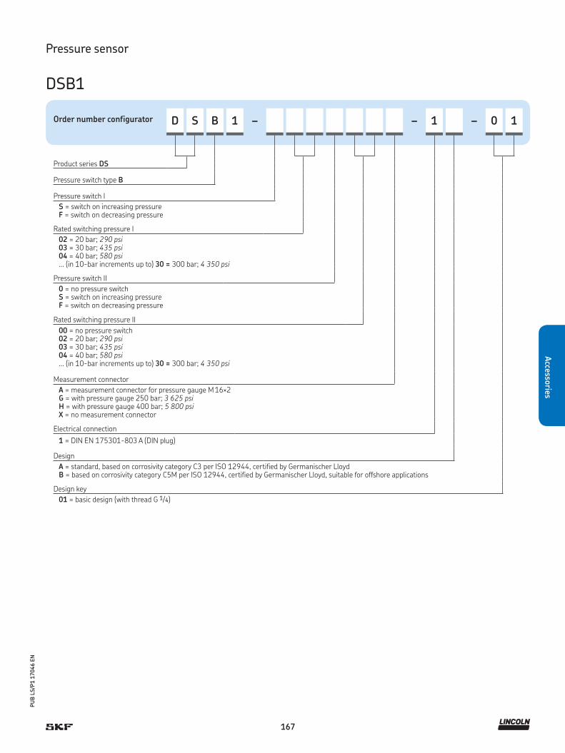
167
PU
B L
S/P
1 1
7046 E
N
Accesso
ries
Order number configurator D S B 1 – – 1 – 0 1
Product series DS
Pressure switch type B
Pressure switch I
S = switch on increasing pressureF = switch on decreasing pressure
Rated switching pressure I
02 = 20 bar; 290 psi03 = 30 bar; 435 psi04 = 40 bar; 580 psi... (in 10-bar increments up to) 30 = 300 bar; 4 350 psi
Pressure switch II
0 = no pressure switch S = switch on increasing pressureF = switch on decreasing pressure
Rated switching pressure II
00 = no pressure switch 02 = 20 bar; 290 psi03 = 30 bar; 435 psi04 = 40 bar; 580 psi... (in 10-bar increments up to) 30 = 300 bar; 4 350 psi
Measurement connector
A = measurement connector for pressure gauge M 16×2G = with pressure gauge 250 bar; 3 625 psiH = with pressure gauge 400 bar; 5 800 psiX = no measurement connector
Electrical connection
1 = DIN EN 175301-803 A (DIN plug)
Design
A = standard, based on corrosivity category C3 per ISO 12944, certified by Germanischer LloydB = based on corrosivity category C5M per ISO 12944, certified by Germanischer Lloyd, suitable for offshore applications
Design key
01 = basic design (with thread G 1/4)
Pressure sensor
DSB1

168
PU
B L
S/P
1 1
7046 E
N
Acc
esso
ries
Technical data
Order number . . . . . . . . . . . . . . . . . DSC1–A040A–1A2AFunction principle . . . . . . . . . . . . . . pressure switchLubricant. . . . . . . . . . . . . . . . . . . . . oil and fluid grease NLGI 000, 00, 0Operating temperature . . . . . . . . . . –10 to +80 °C
14 to 176 °FOperating pressure . . . . . . . . . . . . . max. 100 bar
max. 1 450 psiSwitch type . . . . . . . . . . . . . . . . . . . micro switchContact type . . . . . . . . . . . . . . . . . . change-overOperating voltage . . . . . . . . . . . . . . 10 to 32 V DCPower consumption. . . . . . . . . . . . . max. 50 mAOutput signal. . . . . . . . . . . . . . . . . . 2, PNP transistor stagesVibration resistance. . . . . . . . . . . . . 10 g (5-500 Hz)Service life. . . . . . . . . . . . . . . . . . . . 100 × 106 pressure changesMaterials:Housing. . . . . . . . . . . . . . . . . . . . . .Control panel . . . . . . . . . . . . . . . . .
aluminum, stainless steelpolycarbonate
Electrical connection . . . . . . . . . . . . M 12 × 1, 5-pinPressure port . . . . . . . . . . . . . . . . . G 1/8 (F)Protection class . . . . . . . . . . . . . . . . IP 65Dimensions . . . . . . . . . . . . . . . . . . . 34 × 90,7 × 49,4 mm;
1.33 × 3.57 × 37.4 inMounting position . . . . . . . . . . . . . . any
Pressure sensor
DSC1
Product description
DSC1 pressure switches are electronic pressure switches with inte-
grated digital display for relative pressure measurement. They are
used primarily for pressure monitoring. Depending on the design,
they also can assume control functions. Pressure switch points,
pressure indication, and the switching logic can be configured and
programmed easily. A backlit, four-digit, digital display indicates
switching with LEDs. DSC1 can operate in switching point, hysteresis
and window function modes. The switching mode can be pro-
grammed separately for each output.
Features and benefits
• Available for rising and falling pressures from
0 to 40 bar in 0.2-bar increments
• Micro switch is designed as a change-over switch, can be
used as both a normally closed contact (NC) and
a normally open contact (NO)
• Backlit, four-digit digital display indicates switching
with LEDs on a backlit
• Can operate in switching point, hysteresis and window function
modes
• Encodable access protection
• Digital and analog output
Applications
• Machine tools
• Printing machines
• Wind
• Vehicle
• Steel and heavy industries
!NOTE
For further technical information, technical drawings,
accessories, spare parts or product function descriptions,
see the following publication available on
SKF.com/lubrication: 1-1701-EN
3D data and product configuration:
skf-lubrication.partcommunity.com/3d-cad-models/

169
PU
B L
S/P
1 1
7046 E
N
Accesso
ries
!NOTE
For further technical information, technical drawings,
accessories, spare parts or product function descriptions,
see the following publication available on
SKF.com/lubrication: 1-1701-EN
3D data and product configuration:
skf-lubrication.partcommunity.com/3d-cad-models/
Pressure sensor
DSC2
Product description
DSC2 sensors are electronic pressure switches with an integrated
digital display for relative pressure measurement. They are used pri-
marily for pressure monitoring. Depending on the design, they also
can assume control functions. Pressure switch points, pressure indi-
cation and the switching logic can be configured and programmed
easily. The four-digit, digital display that indicates switching with
LEDs. DSC2 can operate in switching point, hysteresis and window
function modes. The switching mode can be programmed separately
for each output.
Features and benefits
• Available for rising and falling pressures
from 0 to 100 bar in 0.5-bar increments
• Micro switch is designed as a change-over switch; can be
used as both a normally closed contact (NC) and a normally
open contact (NO)
• Four-digit, digital display indicates switching with LEDs
• Can operate in switching point, hysteresis and window
function modes
• Diagnostic output based on the DESINA specification
• UL certification
Applications
• Machine tools
• Printing machines
• Wind
• Vehicle
• Steel and heavy industries
Technical data
Order number . . . . . . . . . . . . . . . . DSC2–A100E–2A2BFunction principle . . . . . . . . . . . . . pressure switchLubricant. . . . . . . . . . . . . . . . . . . . oil and fluid grease: 000–0Operating temperature . . . . . . . . . –10 to +80 °C
14 to 176 °FOperating pressure . . . . . . . . . . . . max. 300 bar
max. 4 350 psiSwitch type . . . . . . . . . . . . . . . . . . micro switchContact type . . . . . . . . . . . . . . . . . change-overOperating voltage . . . . . . . . . . . . . 18 to 30 V DCPower consumption. . . . . . . . . . . . max. 35 mAOutput signal. . . . . . . . . . . . . . . . . 2, PNP/NPNVibration resistance. . . . . . . . . . . . 20 g (10–2 000 Hz)Service life. . . . . . . . . . . . . . . . . . . 100 × 106 pressure changes
Material:Housing . . . . . . . . . . . . . . . . . . . . Control panel . . . . . . . . . . . . . . . . .
aluminum, stainless steelpolyester film
Electrical connection . . . . . . . . . . . M 12 × 1, 4-pinPressure port . . . . . . . . . . . . . . . . G 1/4 (F)Protection class . . . . . . . . . . . . . . . IP 67Dimensions . . . . . . . . . . . . . . . . . . 34 × 90,7 × 49,4 mm;
1.33 × 3.57 × 37.4 inMounting position . . . . . . . . . . . . . . any
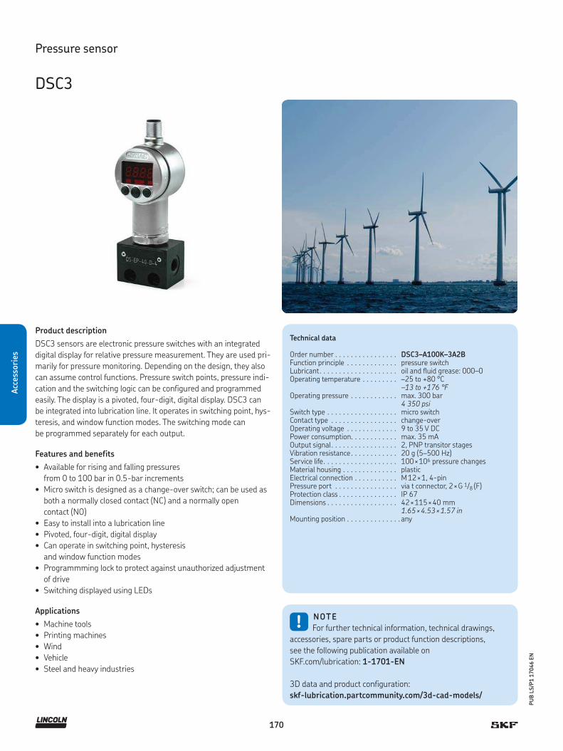
170
PU
B L
S/P
1 1
7046 E
N
Acc
esso
ries
!NOTE
For further technical information, technical drawings,
accessories, spare parts or product function descriptions,
see the following publication available on
SKF.com/lubrication: 1-1701-EN
3D data and product configuration:
skf-lubrication.partcommunity.com/3d-cad-models/
Pressure sensor
DSC3
Product description
DSC3 sensors are electronic pressure switches with an integrated
digital display for relative pressure measurement. They are used pri-
marily for pressure monitoring. Depending on the design, they also
can assume control functions. Pressure switch points, pressure indi-
cation and the switching logic can be configured and programmed
easily. The display is a pivoted, four-digit, digital display. DSC3 can
be integrated into lubrication line. It operates in switching point, hys-
teresis, and window function modes. The switching mode can
be programmed separately for each output.
Features and benefits
• Available for rising and falling pressures
from 0 to 100 bar in 0.5-bar increments
• Micro switch is designed as a change-over switch; can be used as
both a normally closed contact (NC) and a normally open
contact (NO)
• Easy to install into a lubrication line
• Pivoted, four-digit, digital display
• Can operate in switching point, hysteresis
and window function modes
• Programmming lock to protect against unauthorized adjustment
of drive
• Switching displayed using LEDs
Applications
• Machine tools
• Printing machines
• Wind
• Vehicle
• Steel and heavy industries
Technical data
Order number . . . . . . . . . . . . . . . . DSC3–A100K–3A2BFunction principle . . . . . . . . . . . . . pressure switchLubricant. . . . . . . . . . . . . . . . . . . . oil and fluid grease: 000–0Operating temperature . . . . . . . . . –25 to +80 °C
–13 to +176 °FOperating pressure . . . . . . . . . . . . max. 300 bar
4 350 psiSwitch type . . . . . . . . . . . . . . . . . . micro switchContact type . . . . . . . . . . . . . . . . . change-overOperating voltage . . . . . . . . . . . . . 9 to 35 V DCPower consumption. . . . . . . . . . . . max. 35 mAOutput signal. . . . . . . . . . . . . . . . . 2, PNP transitor stagesVibration resistance. . . . . . . . . . . . 20 g (5–500 Hz)Service life. . . . . . . . . . . . . . . . . . . 100 × 106 pressure changesMaterial housing . . . . . . . . . . . . . . plastic Electrical connection . . . . . . . . . . . M 12 × 1, 4-pinPressure port . . . . . . . . . . . . . . . . via t connector, 2 × G 1/8 (F)Protection class . . . . . . . . . . . . . . . IP 67Dimensions . . . . . . . . . . . . . . . . . . 42 × 115 × 40 mm
1.65 × 4.53 × 1.57 inMounting position . . . . . . . . . . . . . . any

171
PU
B L
S/P
1 1
7046 E
N
Accesso
ries
Pressure sensor
247333
Product description
The 24733 analog pressure transducer signals actual system pres-
sure to a monitoring controller. It can be installed in end of single-
line metering device manifolds or by the use of adapters. Comes
with 1,8 m (72 in), shielded, shielded 24-gauge connecting wire.
Maximum length of wire between transducer and monitor
is 9,1 m (30 ft).
Features and benefits
• Analog pressure transducer signals actual system pressure
from 0 bar to 276 bar (0 to 4 000 psi)
• Complete unit with 1,8 m (72 in), shielded,
24-gauge connecting wire
• Installable on end of single-line metering
device manifolds or by the use of adapters
• Sturdy, easy-to-handle product
• Cost-saving alternative to high-end sensors
Applications
• Metalworking
• Material handling equipment
• Off-road applications
• Mobile equipment use
• Food and beverage
Technical data
Order number . . . . . . . . . . . . . . . . . 247333Function principal . . . . . . . . . . . . . . analog pressure transducerLubricant . . . . . . . . . . . . . . . . . . . . oil and fluid grease:
NLGI 000, 00, 0; grease: NLGI 1, 2
Switching pressure range . . . . . . . . 0 to 275 bar 0 to 4 000 psi
Accuracy . . . . . . . . . . . . . . . . . . . . . ±1%Operating pressure . . . . . . . . . . . . . max. 515 bar
max. 7 500 psiOperating temperature . . . . . . . . . . –29 to +82 °C
–20 to +180 °FElectrical input . . . . . . . . . . . . . . . . 10 to 30 V DCVoltage output . . . . . . . . . . . . . . . . 1-6 V DCOffset . . . . . . . . . . . . . . . . . . . . . . . 1 V DCEnclosure . . . . . . . . . . . . . . . . . . . . NEMA 4X RatingPressure port . . . . . . . . . . . . . . . . . 1/4 NPT (m)Electrical connection . . . . . . . . . . . . 24 AWG 360° PVC shielded UL
approvedMaterials . . . . . . . . . . . . . . . . . . . . stainless steelDimensions . . . . . . . . . . . . . . . . . . 16 × 76,2 mm; 0.625 × 3 000 inMounting position . . . . . . . . . . . . . . any

172
PU
B L
S/P
1 1
7046 E
N
Acc
esso
ries
Pressure sensor
DSD
Product description
DSD sensors are single, mechanical-diaphragm pressure switches.
They are used for pressure monitoring and are dependent upon the
mechanical design of resulting pressure and preloaded spring force
of the pressure spring. Under pressure, a pressure plunger carries
the contact washer and moves it to the opposing contact and closes
the electrical circuit. If the pressure is reduced by the amount of hys-
teresis, the switch opens again. On an NC contact, contacts are
made in the opposite way. In single-line systems, it can be integrat-
ed into metering devices at the end of the lubrication line.
Features and benefits
• Available for a pressure rating from 0 to 45 bar
in fixed increments
• Electrical connection is established via screwed contacts, tab
connectors, circular connectors or rectangular plug connectors
• Pressure monitoring, dependent upon the mechanical design of
resulting pressure and preloaded spring force of the
pressure spring
• Mechanical switch can be used as both a normally closed
contact (NC) and a normally open contact (NO)
Applications
• Machine tools, printing machines, vehicles
!NOTE
For further technical information, technical drawings,
accessories, spare parts or product function descriptions,
see the following publication available on
SKF.com/lubrication: 1-1701-EN
3D data and product configuration:
skf-lubrication.partcommunity.com/3d-cad-models/
Technical data
Function principle . . . . . . . . . . . . . pressure switchLubricant. . . . . . . . . . . . . . . . . . . . oil and fluid grease NLGI 000, 00, 0Operating temperature . . . . . . . . . –30 to +100 °C
–22 to +212 °FOperating pressure . . . . . . . . . . . . . static: max. 300 bar
max. 4 350 psidynamic: max. 150 barmax. 2 175 psi
Switch type . . . . . . . . . . . . . . . . . . mechanical diaphragm pressure switch
Contact type . . . . . . . . . . . . . . . . . No, NC (change-over with rectangular plug connector only)
Switching pressure . . . . . . . . . . . . 0,5 to 45 bar; 7.25 to 653 psiContact rating . . . . . . . . . . . . . . . . max. 18 VA, 90 VA, 100 VASwitching voltage/current . . . . . . . 36 V DC / 2.5 A / 0,5 A
250 V AC / 5 AElectrical connection . . . . . . . . . . . M 3 or M 12 × 1 or
DIN EN 175301-803-APressure port . . . . . . . . . . . . . . . . M 10 × 1 taper
Materials:Contact . . . . . . . . . . . . . . . . . . . . . Housing. . . . . . . . . . . . . . . . . . . . . Membrane. . . . . . . . . . . . . . . . . . .
silver platedsteel, galvanized, Cr6-freeNBR
Protection class . . . . . . . . . . . . . . . IP 65Dimensions . . . . . . . . . . . . . . . . . . depending on model, ø × h
27,7 × 50 mm; 1.09 × 1.97 in31,2 × 85 mm; 1.23 × 3.35 in
Mounting position . . . . . . . . . . . . . . any
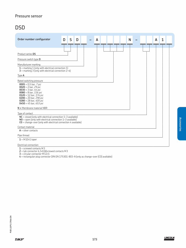
173
PU
B L
S/P
1 1
7046 E
N
Accesso
ries
Order number configurator D S D – A N – A 1
Product series DS
Pressure switch type D
Manufacturer marking
1 = marking 1 (only with electrical connection 1)3 = marking 3 (only with electrical connection 2–4)
Type A
Rated switching pressure
0005 = 0,5 bar, 7 psi0020 = 2 bar, 29 psi0030 = 3 bar, 44 psi0080 = 8 bar, 116 psi0120 = 12 bar, 174 psi0200 = 20 bar, 290 psi0280 = 28 bar, 405 psi0450 = 45 bar, 653 psi
N = Membrane material NBR
Type of contact
NC = closed (only with electrical connection 1–3 available)NO = open (only with electrical connection 1–3 available)CO = change-over (only with electrical connection 4 available)
Contact material
A = silver contacts
Pipe thread
1 = M 10×1 taper
Electrical connection
1 = screwed contacts M 32 = tab connector 6,3×0,8/screwed contacts M 33 = circular connector M 12×14 = rectangular plug connector DIN EN 175301-803-A (only as change-over (CO) available)
Pressure sensor
DSD
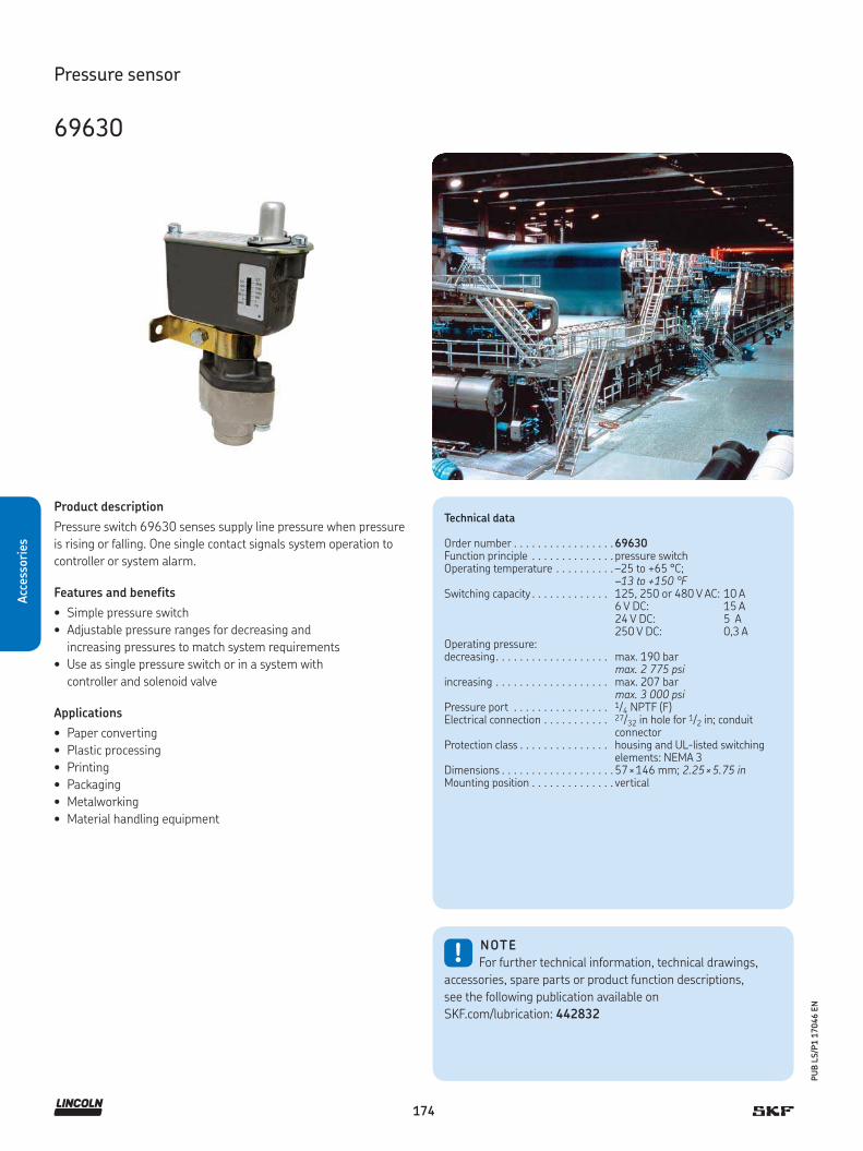
174
PU
B L
S/P
1 1
7046 E
N
Acc
esso
ries
Pressure sensor
69630
Product description
Pressure switch 69630 senses supply line pressure when pressure
is rising or falling. One single contact signals system operation to
controller or system alarm.
Features and benefits
• Simple pressure switch
• Adjustable pressure ranges for decreasing and
increasing pressures to match system requirements
• Use as single pressure switch or in a system with
controller and solenoid valve
Applications
• Paper converting
• Plastic processing
• Printing
• Packaging
• Metalworking
• Material handling equipment
!NOTE
For further technical information, technical drawings,
accessories, spare parts or product function descriptions,
see the following publication available on
SKF.com/lubrication: 442832
Technical data
Order number . . . . . . . . . . . . . . . . . 69630Function principle . . . . . . . . . . . . . . pressure switchOperating temperature . . . . . . . . . . –25 to +65 °C;
–13 to +150 °F Switching capacity . . . . . . . . . . . . . 125, 250 or 480 V AC: 10 A
6 V DC: 15 A 24 V DC: 5 A 250 V DC: 0,3 A
Operating pressure:decreasing. . . . . . . . . . . . . . . . . . . max. 190 bar
max. 2 775 psiincreasing . . . . . . . . . . . . . . . . . . . max. 207 bar
max. 3 000 psiPressure port . . . . . . . . . . . . . . . . 1/4 NPTF (F)Electrical connection . . . . . . . . . . . 27/32 in hole for 1/2 in; conduit
connectorProtection class . . . . . . . . . . . . . . . housing and UL-listed switching
elements: NEMA 3Dimensions . . . . . . . . . . . . . . . . . . . 57 × 146 mm; 2.25 × 5.75 inMounting position . . . . . . . . . . . . . . vertical

175
PU
B L
S/P
1 1
7046 E
N
Accesso
ries
Pressure sensor
234-11145-3, -4, -5, -9
Product description
These maintenance-free electronic pressure sensors are suitable for
pressure measurements for gases and fluids. They are user friendly
and can be applied easily in standard or superior applications. The
space-saving housing is pivotable up to 320° for optimal readability
of the 4-digit, digital display. One or two switching outputs and an
analog output signal for switching point and hysteresis. Both can be
adjusted via push buttons. Different value units such as bar, mbar,
psi or MPa can be selected.
Features and benefits
• Menu-guided adjustments via 2 push buttons
• Indication of status of outputs
• Pre-adjustable hysteresis
• Programmable parameters
• Password protected
• Reverse polarity protection of the supply voltage, excess voltage,
override and short circuit protection are provided
• Compact housing with 320 (degree symbol) pivot
• For standard and superior applications
Applications
• Marine
• Off-shore applications
• Wind
• Vehicle
• Steel and heavy industries
Technical data
Order number.. . . . . . . . . . . . . . . . . 234-11145-...Function principle . . . . . . . . . . . . . . digital pressure switchLubricant. . . . . . . . . . . . . . . . . . . . oil and fluid grease NLGI 000–00,
grease NLGI 1 ,2Operating temperature . . . . . . . . . . –25 to +125 °C; –134 to +185 °FOperating pressure . . . . . . . . . . . . . max. 600 bar; max. 8 700 psi
234-11145-5:max. 400 bar; max. 5 800 psi
Operating voltage . . . . . . . . . . . . . . 18–36 V DCOperating current . . . . . . . . . . . . . . max. 500 mACurrent draw . . . . . . . . . . . . . . . . . . ≤ 50 mAOutput signal. . . . . . . . . . . . . . . . . . 1 or 2 × PNP; 1 analog, digital,
NO or NC adjustableSwitching frequency . . . . . . . . . . . . max. 200 HzSwitching point adjusted . . . . . . . . . 234-1145-5: 175 bar; 2 465 psi Material:Housing . . . . . . . . . . . . . . . . . . . . . PA6.6, stainless steel, FKMMeasuring cell . . . . . . . . . . . . . . . . ceramics AI203Apapter . . . . . . . . . . . . . . . . . . . . . . stainless steel
Electrical connection . . . . . . . . . . . . M 12 × 1; 4 pin plugPressure port . . . . . . . . . . . . . . . . . G 1/4 or G 3/8; DIN3852Protection class . . . . . . . . . . . . . . . . IP 67; EC 60529Dimensions . . . . . . . . . . . . . . . . . . . min. 34 × 94 × 49 mm
min. 1.34 × 3.7 × 1.9 inmax. 34 × 134,5 × 49 mm max. 1.34 × 5.3 × 1.9 in
Mounting position . . . . . . . . . . . . . . any
Order number
Order number Designation
234-11145-3 1 × PNP, 4-20 MA, with adapter G 1/4 and connector234-11145-4 1 × PNP, 4-20 MA, basic model234-11145-5 2 × PNP, 0-20 MA, with adapter G 1/4 and connector,
front flushed234-11145-9 1 × PNP, 4-20 MA, with adapter G3/8 and connector

176
PU
B L
S/P
1 1
7046 E
N
Acc
esso
ries
Pressure sensor
234-10330-4
Product description
This electronic pressure switch has a 4-digit, digital display, two
switching outputs and an analog output signal for switching point
and hysteresis. Both can be adjusted via push buttons. The water-
proofed housing is pivotable up to 290° for optimal readability of
digital display. The pressure switch is virtually maintenance free.
Features and benefits
• Menu-guided adjustments via 3 push buttons indicating
status of outputs
• Peak value storage
• Adjustable hysteresis and absorption
• Programmable parameters
• Password protected
• Reverse polarity and overvoltage protected; short-circuit proof
Applications
• Machine tools
• Printing machines
• Wind
• Vehicles
• Steel and heavy industries
Technical data
Order number.. . . . . . . . . . . . . . . . . 234-10330-4Function principle . . . . . . . . . . . . . . digital pressure switchLubricant. . . . . . . . . . . . . . . . . . . . oil, fluid grease NLGI 00, 000, 0,
grease NLGI 1 ,2Operating temperature . . . . . . . . . . –20 to +85 °C ; –4 to +185 °FOperating pressure . . . . . . . . . . . . . max. 1 000 bar; max. 14 500 psiAnalog output signal . . . . . . . . . . . . 0/4–20 mA,
apparent ohmic resistance ≤ 500 ΩOperating voltage . . . . . . . . . . . . . . 15–30 V DC, nominal 24 V DCSignal output type . . . . . . . . . . . . . . PNP-TransistorSwitching current . . . . . . . . . . . . . . max. 0,7 ACurrent consumption. . . . . . . . . . . . < 100 mASwitching cycle. . . . . . . . . . . . . . . . . ≥ 20 Mio.Electrical connection . . . . . . . . . . . . M12 × 1; 5 pinPressure port . . . . . . . . . . . . . . . . . G 1/4 (BSPP)
Materials:Housing. . . . . . . . . . . . . . . . . . . . . .Control panel . . . . . . . . . . . . . . . . . .
stainless steel 1.4404, NBRzinc die casting, surface treated
Protection class . . . . . . . . . . . . . . . . IP 67Dimensions . . . . . . . . . . . . . . . . . . . 39,5 × 105,5 × 46,3 mm
1.55 × 4.15 × 1.82 inMounting position . . . . . . . . . . . . . . any
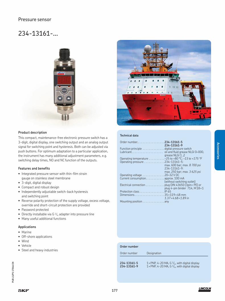
177
PU
B L
S/P
1 1
7046 E
N
Accesso
ries
Pressure sensor
234-13161-...
Product description
This compact, maintenance-free electronic pressure switch has a
3-digit, digital display, one switching output and an analog output
signal for switching point and hysteresis. Both can be adjusted via
push buttons. For optimum adaptation to a particular application,
the instrument has many additional adjustment parameters, e.g.
switching delay times, NO and NC function of the outputs.
Features and benefits
• Integrated pressure sensor with thin-film strain
gauge on stainless steel membrane
• 3-digit, digital display
• Compact and robust design
• Independently adjustable switch-back hysteresis
and switching point
• Reverse polarity protection of the supply voltage, excess voltage,
override and short-circuit protection are provided
• Password protected
• Directly installable via G 1/4 adapter into pressure line
• Many useful additional functions
Applications
• Marine
• Off-shore applications
• Wind
• Vehicle
• Steel and heavy industries
Technical data
Order number.. . . . . . . . . . . . . . . . . 234-13161-5234-13161-9
Function principle . . . . . . . . . . . . . . digital pressure switchLubricant. . . . . . . . . . . . . . . . . . . . oil and fluid grease NLGI 0–000,
grease NLGI 1 ,2Operating temperature . . . . . . . . . . –25 to +80 °C; –13 to +175 °FOperating pressure . . . . . . . . . . . . . 234-13161-5:
max. 600 bar; max. 8 700 psi234-13161-9:max. 250 bar; max. 3 625 psi
Operating voltage . . . . . . . . . . . . . . 20–32 V DCCurrent consumption. . . . . . . . . . . . approx. 100 mA
(without switching outlet)Electrical connection . . . . . . . . . . . . plug DIN 43650 (3pin+ PE) or
plug 4-pin binder 714, M 18 × 1Protection class . . . . . . . . . . . . . . . . IP 65Dimensions . . . . . . . . . . . . . . . . . . . 35 × 119 × 48 mm
1.37 × 4.68 × 1.89 inMounting position . . . . . . . . . . . . . . any
Order number
Order number Designation
234-13161-5 1 × PNP, 4-20 MA, G 1/4, with digital display234-13161-9 1 × PNP, 4-20 MA, G 1/4, with digital display

178
PU
B L
S/P
1 1
7046 E
N
Acc
esso
ries
Pressure sensor
234-10663-1
Product description
This maintenance-free electronic pressure switch is suitable for
pressure control using its internal, stainless steel diaphragm. It has a
4-digit, digital display, two solid state contacts and one analog out-
put for switching point and hysteresis. Both can be adjusted via push
buttons. The housing is pivotable for optimal readability of the digital
display.
Features and benefits
• Alphanumeric, 4-digit display
• Microprocessor controlled
• Self monitoring with error display
• Scalable analog output
• Programmable parameters via keypad
• Adjustable password protection
• Reverse polarity and over-voltage protected; short-circuit proof
• Rugged, stainless steel construction
Applications
• Machine tools
• Chemical techniques
• Wind, vehicle, steel and heavy industries
• Automation technics
Technical data
Order number.. . . . . . . . . . . . . . . . . 234-10663-1Function principal . . . . . . . . . . . . . . digital pressure switchLubricant . . . . . . . . . . . . . . . . . . . . oil and fluid grease NLGI 00, 000, 0
grease NLGI 1, 2Operating temperature . . . . . . . . . . –25 to +100 °C ; –13 to +212°FOpreating pressure . . . . . . . . . . . . . max. 600 bar; max. 8 700 psiOperating elements . . . . . . . . . . . . . 3 easy-response push buttonsProtection class . . . . . . . . . . . . . . . . IP 65 with plugPressure port . . . . . . . . . . . . . . . . . G 1/4 M flush diaphragm
for viscous mediaPre-adjusted pressure metering . . . 220 bar; 3 190 psiMeasuring ranges . . . . . . . . . . . . . . 0.2-50 bar; 2.9-725 psi Electrical connection . . . . . . . . . . . . M12 × 1; 4 pin for plugCurrent output. . . . . . . . . . . . . . . . . 4-20 mA, apparent ohmic
resistance 600 Ω at 24 V DCPower supply. . . . . . . . . . . . . . . . . . 18-32 V DC reversed
polarity protected (SELV, PELV)Digital display . . . . . . . . . . . . . . . . . 4-digit dot-matrix displayPower consumption. . . . . . . . . . . . . approx. 40 mA at 24 V DCMaterials:Wetted parts . . . . . . . . . . . . . . . . . . stainless steel 1.4301Electronics housing . . . . . . . . . . . . . stainless steel 1.4571Seals . . . . . . . . . . . . . . . . . . . . . . . . FKMDimensions (WxH). . . . . . . . . . . . . . 32 × 120 mm
1.26 × 4.72 inMounting position . . . . . . . . . . . . . . any

179
PU
B L
S/P
1 1
7046 E
N
Accesso
ries
Pressure sensor
234-10825-8
Product description
This pressure switch reliably monitors pressure in single-line lubri-
cation systems at a pre-adjusted pressure value. When adjusted val-
ue is reached, pressure switch opens or closes an electric circuit via
a defined piston stroke (depending on pressure power and pre-load
spring). A micro switch can be used for DC or AC voltage. The switch's
housing can be pivoted up to 360 (degree symbol). The pre-adjusted
switching point pressure value is set at the factory.
Features and benefits
• Simple, mechanically operated pressure switch
• Designed as a change-over pressure switch
• Monitors a pre-adjusted pressure value
• Suitable for DC and AC voltage
• Pivotable housing up to 360°
• Maintenance free
Applications
• Machine tools
• Construction machinery
• Wind energy
• Vehicle
• Steel and heavy industries
Technical data
Order number.. . . . . . . . . . . . . . . . . 234-10825-8Function principle . . . . . . . . . . . . . . rotatable pressure switchLubricant. . . . . . . . . . . . . . . . . . . . oil and fluid grease NLGI 000, 00Operating temperature . . . . . . . . . . –25 to +85 °C
–40 to +185 °FOperating pressure . . . . . . . . . . . . . max. 400 bar
max. 5 800 psiSwitching pressure . . . . . . . . . . . . . 100 to 400 bar
1 450 to 5 800 psiAdjustability. . . . . . . . . . . . . . . . . . . under pressureOperating voltage . . . . . . . . . . . . . . adjustable:
30 to 250 V DC; 125; 250 V ACLoad resistance . . . . . . . . . . . . . . . . 0,25-5 ALoad inductive . . . . . . . . . . . . . . . . . 0,25-5 ASwitch type . . . . . . . . . . . . . . . . . . . micro switch with spring-loaded
pistonContact type . . . . . . . . . . . . . . . . . . change-overContact electrical . . . . . . . . . . . . . . . plug connector DIN72585
ø 2,5 mmMaterial:Housing. . . . . . . . . . . . . . . . . . . . . .Contact electrical . . . . . . . . . . . . . . .
zinc-coated steel, URelectroplated silver gilt
Protection class . . . . . . . . . . . . . . . . IP 67, IP 6K9KDimensions . . . . . . . . . . . . . . . . . . . 30 × 74 mm; 1.18 × 2.91 inMounting position . . . . . . . . . . . . . . any, but preferably vertical

Accessories for single-line lubrication systems
180
PU
B L
S/P
1 1
7046 E
N
Acc
esso
ries
Acc
esso
ries
Solenoid valves
Acc
esso
ries
35028335024 ... 253-14076-X
525-320-XX-1 161-110-031
35024 ...
161-140-050

181
PU
B L
S/P
1 1
7046 E
N
Accesso
ries
PU
B L
S/P
2 X
XX
XX E
N
Overview of solenoid valves
Solenoid valves
Product Type Operating pressuremax.
Operating temperature Voltage Page
bar psi °C °F V DC V AC
350241 3-way 10,3 150 -18 to +60 0 to 140 – 110–240 182350242 3-way 10,3 150 -18 to +60 0 to 140 – 110–240 182350244 4-way 10,3 150 -18 to +49 0 to 120 – 110–240 182350245 4-way 10,3 150 -18 to +49 0 to 120 – 110–240 182
350282 3-way 10,3 150 -18 to +60 0 to 140 12 – 183350283 3-way 10,3 150 -18 to +60 0 to 140 24 – 183
253-14076-6 3/2-way 0,5–16 7.3–232 -10 to +55 14 to 131 – 110 184253-14076-7 3/2-way 0,5–16 7.3–232 -10 to +55 14 to 131 – 230 184
525-32085-1 3/2-way 0–400 0–5 800 -20 to +60 -4 to +140 24 – 185525-32086-1 3/2-way 0–400 0–5 800 -20 to +60 -4 to +140 – 110 185525-32087-1 3/2-way 0–400 0–5 800 -20 to +60 -4 to +140 – 230 185
161-110-031 2/2-way max. 500 max. 7 250 -25 to +80 -13 to +176 24 – 186161-140-050 4/2-way max. 320 max. 4 350 -25 to +80 -13 to +176 24 220 187

182
PU
B L
S/P
1 1
7046 E
N
Acc
esso
ries
Solenoid valve
35024 ...
Product description
Electric solenoid-operated air valves 350241 to 350245 operate
as 3-way or 4-way solenoid air valves. They are used to operate sin-
gle-stroke or reciprocating-stroke, air-controlled pumps in single-
line systems. Timer- and pressure-controlled air is supplied to the
pumps, activating air-powered forward strokes and spring-
(3-way) or air-powered (4-way) return strokes. In doing so, pumps
discharge lubricant to the connected metering devices.
Features and benefits
• Timer- and pressure-controlled pump operation
• Use as 3-way or 4-way solenoid valves
• For operation of single-stroke or reciprocating-stroke pumps
• Flexible usage selectable on electrical V AC power requirements
Applications
• Mining and mineral processing
• Heavy machines
Technical data
Function principle Model 350241, 350242 . . . . . 3-way, solenoid-operated air valveModel 350244, 350245 . . . . . 4-way, solenoid-operated air valve
Operating temperature350241, 350242 . . . . . . . . . . –18 to +60 °C, 0 to +140 °F350244, 350245 . . . . . . . . . . –18 to +49 °C, 0 to +120 °FOperating pressure . . . . . . . . . max. 10 bar; 150 psiOperating voltage . . . . . . . . . . 110–240 V ACCurrent . . . . . . . . . . . . . . . . . . 8,4 A
Current inrush Model 350241, 350244 . . . . . 0,11 AModel 350242, 350245 . . . . . 0,055 A
Current holding Model 350241, 350244 . . . . . 0,7 AModel 350242, 350245 . . . . . 0,35 AAir inlet/outlet . . . . . . . . . . . . . 1/4 NPT (F)Conduit connection . . . . . . . . . 1/2 NPS (F)Mounting position . . . . . . . . . . any
Order number
Order number Operating voltage Type
350241 110 V AC, 50 Hz, 120 V AC, 60 Hz, 8,4 VA 3-way350242 220 V AC, 50 Hz, 240 V AC, 60 Hz, 8,4 VA 3-way350244 110 V AC, 50 Hz, 120 V AC, 60 Hz, 8,4 VA 4-way350245 220 V AC, 50 Hz, 240 V AC, 60 Hz, 8.4 VA 4-way

183
PU
B L
S/P
1 1
7046 E
N
Accesso
ries
Solenoid valve
350282, 350283
Product description
Electric solenoid-operated air valves 350282 and 350283 operate
as DC 3-way solenoid air valves. They are used to operate single-
stroke, air-controlled pumps in single-line systems.Timer- and
pressure-controlled air is supplied to the pumps, activating air-pow-
ered forward strokes and spring- (3-way) return strokes. In doing
so, pumps discharge lubricant to the connected metering devices.
Features and benefits
• Timer- and pressure-controlled pump operation
• Use as 3-way solenoid valves
• For operation of single-stroke pumps
• Flexible usage selectable on electrical 12 or
24 V DC power requirements
Applications
• Mining and mineral processing
• Heavy machines
!NOTE
For further technical information, technical drawings,
accessories, spare parts or product function descriptions,
see the following publication available on
SKF.com/lubrication: 442832
Technical data
Order number . . . . . . . . . . . . . . . . . . . . 350282, 350283Function principle . . . . . . . . . . . . . . . . . 3-way solenoid air valve
Voltage supply:350282. . . . . . . . . . . . . . . . . . . . . . . . . 12 V DC, 6 VA350283. . . . . . . . . . . . . . . . . . . . . . . . . 24V DC, 6 VAOperating temperature . . . . . . . . . . . . . –18 to +60 °C, 0 to +140 °FOperating pressure . . . . . . . . . . . . . . . . max. 10 bar; 150 psiAir inlet/outlet . . . . . . . . . . . . . . . . . . . . 1/8 NPT (F)Cv factor . . . . . . . . . . . . . . . . . . . . . . . . 0.18Mounting position . . . . . . . . . . . . . . . . . any
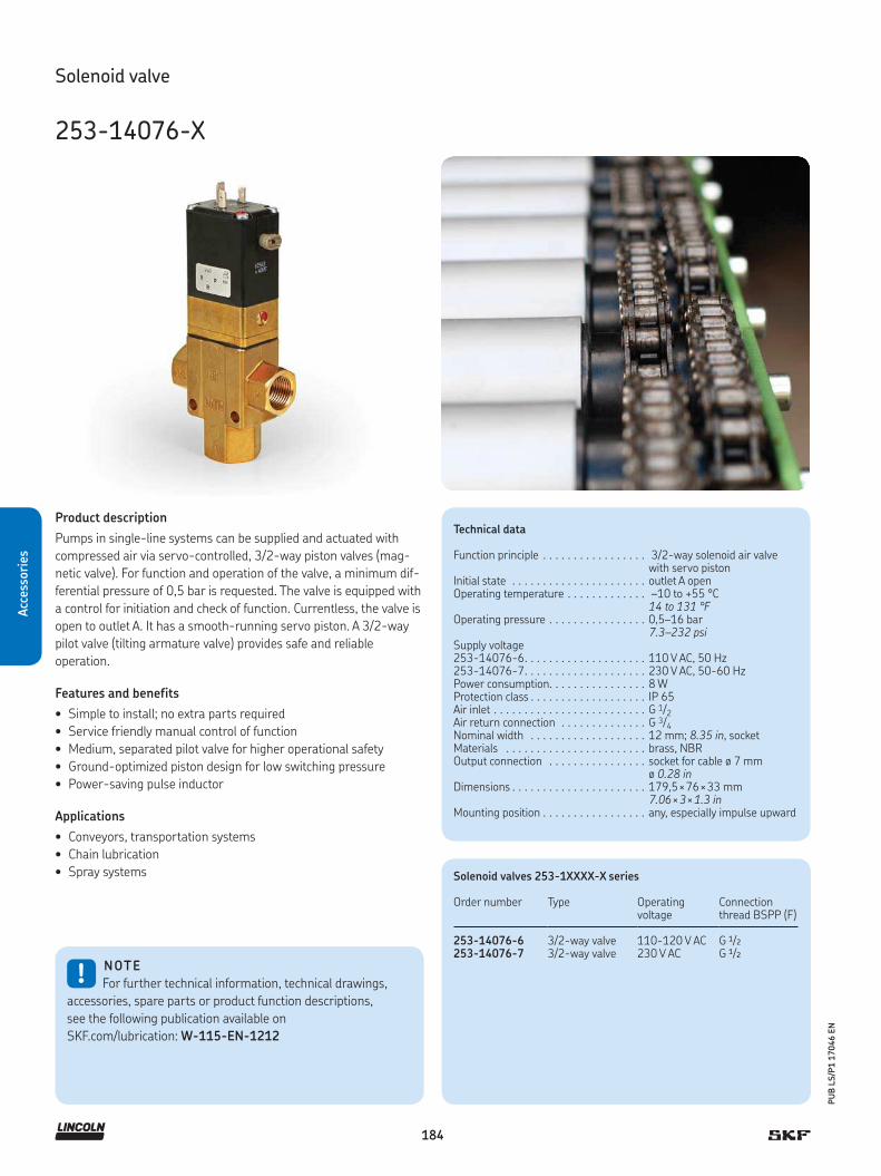
184
PU
B L
S/P
1 1
7046 E
N
Acc
esso
ries
Solenoid valve
253-14076-X
Product description
Pumps in single-line systems can be supplied and actuated with
compressed air via servo-controlled, 3/2-way piston valves (mag-
netic valve). For function and operation of the valve, a minimum dif-
ferential pressure of 0,5 bar is requested. The valve is equipped with
a control for initiation and check of function. Currentless, the valve is
open to outlet A. It has a smooth-running servo piston. A 3/2-way
pilot valve (tilting armature valve) provides safe and reliable
operation.
Features and benefits
• Simple to install; no extra parts required
• Service friendly manual control of function
• Medium, separated pilot valve for higher operational safety
• Ground-optimized piston design for low switching pressure
• Power-saving pulse inductor
Applications
• Conveyors, transportation systems
• Chain lubrication
• Spray systems
!NOTE
For further technical information, technical drawings,
accessories, spare parts or product function descriptions,
see the following publication available on
SKF.com/lubrication: W-115-EN-1212
Technical data
Function principle . . . . . . . . . . . . . . . . . 3/2-way solenoid air valve with servo piston
Initial state . . . . . . . . . . . . . . . . . . . . . . outlet A openOperating temperature . . . . . . . . . . . . . –10 to +55 °C
14 to 131 °FOperating pressure . . . . . . . . . . . . . . . . 0,5–16 bar
7.3–232 psiSupply voltage253-14076-6. . . . . . . . . . . . . . . . . . . . 110 V AC, 50 Hz253-14076-7. . . . . . . . . . . . . . . . . . . . 230 V AC, 50-60 HzPower consumption. . . . . . . . . . . . . . . . 8 WProtection class . . . . . . . . . . . . . . . . . . . IP 65Air inlet . . . . . . . . . . . . . . . . . . . . . . . . . G 1/2Air return connection . . . . . . . . . . . . . . G 3/4Nominal width . . . . . . . . . . . . . . . . . . . 12 mm; 8.35 in, socketMaterials . . . . . . . . . . . . . . . . . . . . . . . brass, NBROutput connection . . . . . . . . . . . . . . . . socket for cable ø 7 mm
ø 0.28 inDimensions . . . . . . . . . . . . . . . . . . . . . . 179,5 × 76 × 33 mm
7.06 × 3 × 1.3 inMounting position . . . . . . . . . . . . . . . . . any, especially impulse upward
Solenoid valves 253-1XXXX-X series
Order number Type Operating voltage
Connection thread BSPP (F)
253-14076-6 3/2-way valve 110-120 V AC G 1/2
253-14076-7 3/2-way valve 230 V AC G 1/2
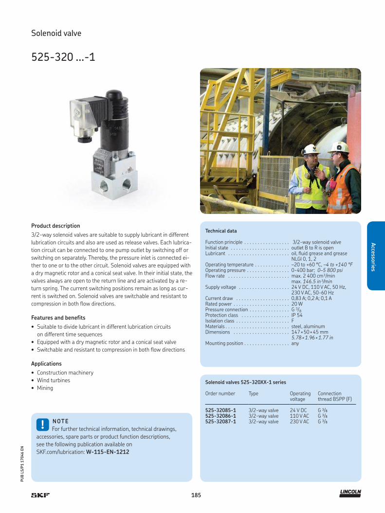
185
PU
B L
S/P
1 1
7046 E
N
Accesso
ries
Solenoid valve
525-320 ...-1
Product description
3/2-way solenoid valves are suitable to supply lubricant in different
lubrication circuits and also are used as release valves. Each lubrica-
tion circuit can be connected to one pump outlet by switching off or
switching on separately. Thereby, the pressure inlet is connected ei-
ther to one or to the other circuit. Solenoid valves are equipped with
a dry magnetic rotor and a conical seat valve. In their initial state, the
valves always are open to the return line and are activated by a re-
turn spring. The current switching positions remain as long as cur-
rent is switched on. Solenoid valves are switchable and resistant to
compression in both flow directions.
Features and benefits
• Suitable to divide lubricant in different lubrication circuits
on different time sequences
• Equipped with a dry magnetic rotor and a conical seat valve
• Switchable and resistant to compression in both flow directions
Applications
• Construction machinery
• Wind turbines
• Mining
!NOTE
For further technical information, technical drawings,
accessories, spare parts or product function descriptions,
see the following publication available on
SKF.com/lubrication: W-115-EN-1212
Technical data
Function principle . . . . . . . . . . . . . . . . . 3/2-way solenoid valve Initial state . . . . . . . . . . . . . . . . . . . . . . outlet B to R is openLubricant . . . . . . . . . . . . . . . . . . . . . . . oil, fluid grease and grease
NLGI 0, 1, 2Operating temperature . . . . . . . . . . . . . –20 to +60 °C, –4 to +140 °FOperating pressure . . . . . . . . . . . . . . . . 0-400 bar; 0–5 800 psiFlow rate . . . . . . . . . . . . . . . . . . . . . . . max. 2 400 cm³/min
max. 146.5 in³/minSupply voltage . . . . . . . . . . . . . . . . . . . 24 V DC, 110 V AC, 50 Hz,
230 V AC, 50-60 HzCurrent draw . . . . . . . . . . . . . . . . . . . . 0,83 A; 0,2 A; 0,1 ARated power . . . . . . . . . . . . . . . . . . . . . 20 WPressure connection . . . . . . . . . . . . . . . G 3/8Protection class . . . . . . . . . . . . . . . . . . IP 54Isolation class . . . . . . . . . . . . . . . . . . . . FMaterials . . . . . . . . . . . . . . . . . . . . . . . . steel, aluminumDimensions . . . . . . . . . . . . . . . . . . . . . 147 × 50 × 45 mm
5.78 × 1.96 × 1.77 inMounting position . . . . . . . . . . . . . . . . . any
Solenoid valves 525-320XX-1 series
Order number Type Operating voltage
Connection thread BSPP (F)
525-32085-1 3/2-way valve 24 V DC G 3/8
525-32086-1 3/2-way valve 110 V AC G 3/8
525-32087-1 3/2-way valve 230 V AC G 3/8
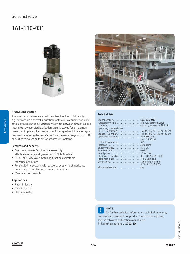
186
PU
B L
S/P
1 1
7046 E
N
Acc
esso
ries
Soleonid valve
161-110-031
Product description
The directional valves are used to control the flow of lubricants,
e.g. to divide up a central lubrication system into a number of lubri-
cation circuits (zoned actuation) or to switch between circulating and
intermittently operated lubrication circuits. Valves for a maximum
pressure of up to 45 bar can be used for single-line lubrication sys-
tems with metering devices. Valves for a pressure range of up to 300
or 500 bar also are suitable for progressive systems.
Features and benefits
• Directional valves for oil with a low or high
effective viscosity and greases up to NLGI Grade 2
• 2-, 4- or 5-way valve switching functions selectable
for zoned actuations
• For single-line systems with sectional supplying of lubricants
dependent upon different times and quantities
• Manual action possible
Applications
• Paper industry
• Steel industry
• Heavy industry
!NOTE
For further technical information, technical drawings,
accessories, spare parts or product function descriptions,
see the following publication available on
SKF.com/lubrication: 1-1703-EN
Technical data
Order number . . . . . . . . . . . . . . . . . . . . 161-110-031Function principle . . . . . . . . . . . . . . . . . 2/2-way solenoid valveLubricant. . . . . . . . . . . . . . . . . . . . . . . . oil and grease up to NLGI 2Operating temperatures:Oil, 4–1 500 mm/s². . . . . . . . . . . . . . . . –40 to +80 °C; –40 to +176°FGrease, 700 mbar . . . . . . . . . . . . . . . . . –25 to +80 °C; –13 to +176°FOperating pressure . . . . . . . . . . . . . . . . max. 500 bar,
max. 7 250 psiHydraulic connector. . . . . . . . . . . . . . . . G1/4Materials . . . . . . . . . . . . . . . . . . . . . . . . aluminumSupply voltage. . . . . . . . . . . . . . . . . . . . Rated current . . . . . . . . . . . . . . . . . . . . Rated power . . . . . . . . . . . . . . . . . . . . . Electrical connection . . . . . . . . . . . . . . .
24 V DC0,67 A16 W, 5 WDIN EN175301-803
Protection class . . . . . . . . . . . . . . . . . . . IP 65 with plugDimensions . . . . . . . . . . . . . . . . . . . . . . 146,5 × 55 × 45 mm
5.77 × 2.17 × 1.77 inMounting position . . . . . . . . . . . . . . . . . any
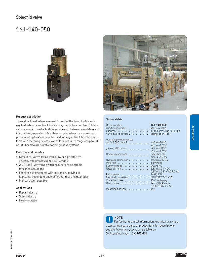
187
PU
B L
S/P
1 1
7046 E
N
Accesso
ries
Soleonid valve
161-140-050
Product description
These directional valves are used to control the flow of lubricants,
e.g. to divide up a central lubrication system into a number of lubri-
cation circuits (zoned actuation) or to switch between circulating and
intermittently operated lubrication circuits. Valves for a maximum
pressure of up to 45 bar can be used for single-line lubrication sys-
tems with metering devices. Valves for a pressure range of up to 300
or 500 bar also are suitable for progressive systems.
Features and benefits
• Directional valves for oil with a low or high effective
viscosity and greases up to NLGI Grade 2
• 2-, 4- or 5-way valve switching functions selectable
for zoned actuations
• For single-line systems with sectional supplying of
lubricants dependent upon different times and quantities
• Manual action possible
Applications
• Paper industry
• Steel industry
• Heavy industry
!NOTE
For further technical information, technical drawings,
accessories, spare parts or product function descriptions,
see the following publication available on
SKF.com/lubrication: 1-1703-EN
Technical data
Order number 161-140-050Function principle . . . . . . . . . . . . . . . . . 4/2-way valveLubricant. . . . . . . . . . . . . . . . . . . . . . . . oil and grease up to NLGI 2Valve, basic position. . . . . . . . . . . . . . . . sliding, open P to A
Operating temperatures:oil, 4-1 500 mm/s² . . . . . . . . . . . . . . . . –40 to +80 °C
–40 to +176°Fgrease, 700 mbar . . . . . . . . . . . . . . . . . –25 to +80 °C
–13 to +176°FOperating pressure . . . . . . . . . . . . . . . . max. 320 bar
max. 4 350 psiHydraulic connector . . . . . . . . . . . . . . . base plate G 1/4Materials . . . . . . . . . . . . . . . . . . . . . . . aluminumSupply voltage . . . . . . . . . . . . . . . . . . . DC and ACRated current . . . . . . . . . . . . . . . . . . . . 1,33 A at 24 V DC;
0,17 A at 220 V AC, 50 HzRated power . . . . . . . . . . . . . . . . . . . . . 16 W, 5 WElectrical connection . . . . . . . . . . . . . . DIN EN175301-803Protection class . . . . . . . . . . . . . . . . . . IP 65 with plugDimensions . . . . . . . . . . . . . . . . . . . . . . 148 × 58 × 45 mm
5.83 × 2.28 × 1.77 inMounting position . . . . . . . . . . . . . . . . . any

188
Index of order numbers
40PGA . . . . . . . . . . . . . . . . . . . . 85
161-120-067+910 . . . . . . . . . . 23
161/120-067+924. . . . . . . . . . . 23
223-12289-7 . . . . . . . . . . . . . 131
234-10330-4 . . . . . . . . . . . . . 163
234-10330-4 . . . . . . . . . . . . . 176
234-10663-1 . . . . . . . . . . . . . 163
234-10663-1 . . . . . . . . . . . . . 178
234-10825-8 . . . . . . . . . . . . . 163
234-10825-8 . . . . . . . . . . . . . 179
234-11145-... . . . . . . . . . . . . . 175
234-11145-3/4/5/9 . . . . . . . . 163
234-13161-5 . . . . . . . . . . . . . 177
234-13161-5/9 . . . . . . . . . . . . 163
234-13161-5
234-13161-9 . . . . . . . . . . . . . 177
234-13161-9 . . . . . . . . . . . . . 177
236-10153-3 . . . . . . . . . . . . . 160
236-10986-1 . . . . . . . . . . . . . 160
237-11204-8 . . . . . . . . . . . . . 105
321-401G1 . . . . . . . . . . . . . . . . 67
321-401G2 . . . . . . . . . . . . . . . . 67
321-401G3 . . . . . . . . . . . . . . . . 67
321-401T2 . . . . . . . . . . . . . . . . 67
321-401W2 . . . . . . . . . . . . . . . . 67
321-403G1 . . . . . . . . . . . . . . . . 67
321-403G2 . . . . . . . . . . . . . . . . 67
321-403G3 . . . . . . . . . . . . . . . . 67
321-403G4 . . . . . . . . . . . . . . . . 67
321-403T1 . . . . . . . . . . . . . . . . 67
321-403T2 . . . . . . . . . . . . . . . . 67
321-403T3 . . . . . . . . . . . . . . . . 67
321-403W1 . . . . . . . . . . . . . . . . 67
321-403W2 . . . . . . . . . . . . . . . . 67
321-403W3 . . . . . . . . . . . . . . . . 67
321-406G1 . . . . . . . . . . . . . . . . 67
321-406G2 . . . . . . . . . . . . . . . . 67
321-406G3 . . . . . . . . . . . . . . . . 67
321-406G4 . . . . . . . . . . . . . . . . 67
321-406T1 . . . . . . . . . . . . . . . . 67
321-406T2 . . . . . . . . . . . . . . . . 67
321-406T3 . . . . . . . . . . . . . . . . 67
321-406W1 . . . . . . . . . . . . . . . . 67
321-406W2 . . . . . . . . . . . . . . . . 67
321-406W3 . . . . . . . . . . . . . . . . 67
321-410G1 . . . . . . . . . . . . . . . . 67
321-410G2 . . . . . . . . . . . . . . . . 67
321-410G3 . . . . . . . . . . . . . . . . 67
321-410G4 . . . . . . . . . . . . . . . . 67
321-410T1 . . . . . . . . . . . . . . . . 67
321-410T2 . . . . . . . . . . . . . . . . 67
321-410T3 . . . . . . . . . . . . . . . . 67
321-410W1 . . . . . . . . . . . . . . . . 67
321-410W2 . . . . . . . . . . . . . . . . 67
321-410W3 . . . . . . . . . . . . . . . . 67
321-601G1 . . . . . . . . . . . . . . . . 67
321-601G2 . . . . . . . . . . . . . . . . 67
321-601T2 . . . . . . . . . . . . . . . . 67
321-601T3 . . . . . . . . . . . . . . . . 67
321-601W1 . . . . . . . . . . . . . . . . 67
321-601W2 . . . . . . . . . . . . . . . . 67
321-601W3 . . . . . . . . . . . . . . . . 67
321-603G1 . . . . . . . . . . . . . . . . 67
321-603G2 . . . . . . . . . . . . . . . . 67
321-603G3 . . . . . . . . . . . . . . . . 67
321-603T1 . . . . . . . . . . . . . . . . 67
321-603T2 . . . . . . . . . . . . . . . . 67
321-603T3 . . . . . . . . . . . . . . . . 67
321-603W1 . . . . . . . . . . . . . . . . 67
321-603W2 . . . . . . . . . . . . . . . . 67
321-603W3 . . . . . . . . . . . . . . . . 67
321-606G1 . . . . . . . . . . . . . . . . 67
321-606G2 . . . . . . . . . . . . . . . . 67
321-606G3 . . . . . . . . . . . . . . . . 67
321-606T2 . . . . . . . . . . . . . . . . 67
321-606T3 . . . . . . . . . . . . . . . . 67
321-606W1 . . . . . . . . . . . . . . . . 67
321-606W2 . . . . . . . . . . . . . . . . 67
321-606W3 . . . . . . . . . . . . . . . . 67
321-610G1 . . . . . . . . . . . . . . . . 67
321-610G2 . . . . . . . . . . . . . . . . 67
321-610G3 . . . . . . . . . . . . . . . . 67
321-610T1 . . . . . . . . . . . . . . . . 67
321-610T2 . . . . . . . . . . . . . . . . 67
321-610T3 . . . . . . . . . . . . . . . . 67
321-610W1 . . . . . . . . . . . . . . . . 67
321-610W2 . . . . . . . . . . . . . . . . 67
321-610W3 . . . . . . . . . . . . . . . . 67
321 G7 . . . . . . . . . . . . . . . . . . . . 47
321 G, G4,
T, W, Module . . . . . . . . . . . . . . . . 47
340 . . . . . . . . . . . . . . . . . . . . . . . 47
340 . . . . . . . . . . . . . . . . . . . . . . . 47
341 . . . . . . . . . . . . . . . . . . . . . . . 47
341 * . . . . . . . . . . . . . . . . . . . . . 47
341-453-K-S8 . . . . . . . . . . . . . . 51
341-456-K-S8 . . . . . . . . . . . . . . 51
341-460-K-S8 . . . . . . . . . . . . . . 51
341-466-K-S8 . . . . . . . . . . . . . . 51
341-853-K . . . . . . . . . . . . . . . . . 51
341-856-K . . . . . . . . . . . . . . . . . 51
341-860-K . . . . . . . . . . . . . . . . . 51
350 . . . . . . . . . . . . . . . . . . . . . . . 47
350 . . . . . . . . . . . . . . . . . . . . . . . 47
351 . . . . . . . . . . . . . . . . . . . . . . . 47
351 * . . . . . . . . . . . . . . . . . . . . . 47
352-005-K . . . . . . . . . . . . . . . . . 59
352-005-K-S8 . . . . . . . . . . . . . . 59
352-005-S8-VS . . . . . . . . . . . . 59
352-005-VS. . . . . . . . . . . . . . . . 59
352-010-K . . . . . . . . . . . . . . . . . 59
352-010-K-S8 . . . . . . . . . . . . . . 59
352-010-K-S82 . . . . . . . . . . . . . 59
352-010-S8-VS . . . . . . . . . . . . 59
352-010-S82-VS . . . . . . . . . . . 59
352-010-VS. . . . . . . . . . . . . . . . 59
352-020-K . . . . . . . . . . . . . . . . . 59
352-020-K-S8 . . . . . . . . . . . . . . 59
352-020-K-S82 . . . . . . . . . . . . . 59
352-020-S8-VS . . . . . . . . . . . . 59
352-020-S82-VS . . . . . . . . . . . 59
352-020-VS. . . . . . . . . . . . . . . . 59
352-030-K-S82 . . . . . . . . . . . . . 59
352-030-S82-VS . . . . . . . . . . . 59
352-040-K . . . . . . . . . . . . . . . . . 59
352-040-K-S8 . . . . . . . . . . . . . . 59
352-040-S8-VS . . . . . . . . . . . . 59
352-040-VS. . . . . . . . . . . . . . . . 59
352-060-K . . . . . . . . . . . . . . . . . 59
352-060-K-S8 . . . . . . . . . . . . . . 59
352-060-S8-VS . . . . . . . . . . . . 59
352-060-VS. . . . . . . . . . . . . . . . 59
361 . . . . . . . . . . . . . . . . . . . . . . . 47
361 . . . . . . . . . . . . . . . . . . . . . . . 47
370 . . . . . . . . . . . . . . . . . . . . . . . 47
390 . . . . . . . . . . . . . . . . . . . . . . . 47
390 . . . . . . . . . . . . . . . . . . . . . . . 47
391 . . . . . . . . . . . . . . . . . . . . . . . 47
391 . . . . . . . . . . . . . . . . . . . . . . . 47
391-010-K-S1 . . . . . . . . . . . . . . 65
391-020-K . . . . . . . . . . . . . . . . . 65
391-020-K-S1 . . . . . . . . . . . . . . 65
391-020-K-S8 . . . . . . . . . . . . . . 65
391-030-K-S1 . . . . . . . . . . . . . . 65
391-040-K . . . . . . . . . . . . . . . . . 65
391-040-K-S8 . . . . . . . . . . . . . . 65
391-060-K . . . . . . . . . . . . . . . . . 65

189
Index of order numbers
391-060-K-S8 . . . . . . . . . . . . . . 65
391-100-K . . . . . . . . . . . . . . . . . 65
391-100-K-S8 . . . . . . . . . . . . . . 65
391-150-K . . . . . . . . . . . . . . . . . 65
391-150-K-S8 . . . . . . . . . . . . . . 65
406-004-VS. . . . . . . . . . . . . . . . 23
408-004-VS. . . . . . . . . . . . . . . . 23
447-71899-1 . . . . . . . . . . . . . . 73
447-71901-1 . . . . . . . . . . . . . . 73
447-71902-1 . . . . . . . . . . . . . . 73
447-71903-1 . . . . . . . . . . . . . . 73
447-71904-1 . . . . . . . . . . . . . . 73
447-71905-1 . . . . . . . . . . . . . . 73
447-71906-1 . . . . . . . . . . . . . . 73
454-71505-1 . . . . . . . . . . . . . 131
454-71506-1 . . . . . . . . . . . . . 131
454-71507-1 . . . . . . . . . . . . . 131
454-71508-1 . . . . . . . . . . . . . 131
454-71509-1 . . . . . . . . . . . . . 131
466-421-001 . . . . . . . . . . . . . . 23
506-140-VS. . . . . . . . . . . . . . . . 23
525-32083-1 . . . . . . . . . . . . . 119
532-34839-2 . . . . . . . . . . . . . 160
532-34839-3 . . . . . . . . . . . . . 160
532-34839-5 . . . . . . . . . . . . . 160
532-34839-6 . . . . . . . . . . . . . 160
532-37731-1 . . . . . . . . . . . . . 160
547-33924-1 . . . . . . . . . . . . . 73
547-33925-1 . . . . . . . . . . . . . . 73
547-33926-1 . . . . . . . . . . . . . . 73
554-32810-1 . . . . . . . . . . . . . 131
554-32811-1 . . . . . . . . . . . . . 131
554-32812-1 . . . . . . . . . . . . . 131
554-32813-1 . . . . . . . . . . . . . 131
554-32814-1 . . . . . . . . . . . . . 131
554-34387-1 . . . . . . . . . . . . . 131
645-41062-3 . . . . . . . . . . . . . 107
645-41062-4 . . . . . . . . . . . . . 107
645-41062-7 . . . . . . . . . . . . . 107
645-41062-8 . . . . . . . . . . . . . 107
645-41062-9 . . . . . . . . . . . . . 107
645-41062-9 . . . . . . . . . . . . . 107
645-41064-2 . . . . . . . . . . . . . 107
645-41064-3 . . . . . . . . . . . . . 107
645-41064-4 . . . . . . . . . . . . . 107
645-41064-6 . . . . . . . . . . . . . 107
645-41064-7 . . . . . . . . . . . . . 107
645-41064-8 . . . . . . . . . . . . . 107
645-41073-5 . . . . . . . . . . . . . 107
645-41110-2 . . . . . . . . . . . . . 107
645-41110-3 . . . . . . . . . . . . . 107
645-41119-1 . . . . . . . . . . . . . 107
645-41119-2 . . . . . . . . . . . . . 107
645-41175-5 . . . . . . . . . . . . . 107
647-41151-2 . . . . . . . . . . . . . . 73
647-41152-2 . . . . . . . . . . . . . . 73
647-41152-4 . . . . . . . . . . . . . . 73
647-41153-2 . . . . . . . . . . . . . . 73
647-41154-4 . . . . . . . . . . . . . . 73
647-41154-5 . . . . . . . . . . . . . . 73
647-41154-6 . . . . . . . . . . . . . . 73
647-41154-7 . . . . . . . . . . . . . . 73
647-41155-2 . . . . . . . . . . . . . . 73
647-41156-2 . . . . . . . . . . . . . . 73
664-34135-6 . . . . . . . . . . . . . 155
664-34135-7 . . . . . . . . . . . . . 155
995-901-061 . . . . . . . . . . . . . . 23
995-901-063 . . . . . . . . . . . . . . 23
995-993-610 . . . . . . . . . . . . . . 59
995-993-610-VS . . . . . . . . . . . 59
995-993-620 . . . . . . . . . . . . . . 59
995-993-620-VS . . . . . . . . . . . 59
995-993-630 . . . . . . . . . . . . . . 59
995-993-630-VS . . . . . . . . . . . 59
995-993-660 . . . . . . . . . . . . . . 59
995-994-003 . . . . . . . . . . . . . . 51
995-994-006 . . . . . . . . . . . . . . 51
995-994-010 . . . . . . . . . . . . . . 51
995-994-016 . . . . . . . . . . . . . . 51
995-994-103 . . . . . . . . . . . . . . 51
995-994-103-VS . . . . . . . . . . . 51
995-994-106 . . . . . . . . . . . . . . 51
995-994-110 . . . . . . . . . . . . . . 51
995-994-116 . . . . . . . . . . . . . . 51
1810 . . . . . . . . . . . . . . . . . . . . . . 85
1810 . . . . . . . . . . . . . . . . . . . . . . 89
1826 . . . . . . . . . . . . . . . . . . . . . . 29
11962 . . . . . . . . . . . . . . . . . . . . . 79
11962 . . . . . . . . . . . . . . . . . . . . . 81
11963 . . . . . . . . . . . . . . . . . . . . . 79
11963 . . . . . . . . . . . . . . . . . . . . . 81
11964 . . . . . . . . . . . . . . . . . . . . . 79
11964 . . . . . . . . . . . . . . . . . . . . . 81
11965 . . . . . . . . . . . . . . . . . . . . . 79
11965 . . . . . . . . . . . . . . . . . . . . . 81
12658 . . . . . . . . . . . . . . . . . . . . . 79
12658 . . . . . . . . . . . . . . . . . . . . . 81
14253 . . . . . . . . . . . . . . . . . . . . . 75
14312 . . . . . . . . . . . . . . . . . . . . . 75
14361 . . . . . . . . . . . . . . . . . . . . . 75
69630 . . . . . . . . . . . . . . . . . . . . 158
69630 . . . . . . . . . . . . . . . . . . . . 163
69630 . . . . . . . . . . . . . . . . . . . . 174
80072 . . . . . . . . . . . . . . . . . . . . 115
80073 . . . . . . . . . . . . . . . . . . . . 115
80074 . . . . . . . . . . . . . . . . . . . . 115
80075 . . . . . . . . . . . . . . . . . . . . 115
80076 . . . . . . . . . . . . . . . . . . . . 115
80077 . . . . . . . . . . . . . . . . . . . . 115
80078 . . . . . . . . . . . . . . . . . . . . 115
80079 . . . . . . . . . . . . . . . . . . . . 115
80080 . . . . . . . . . . . . . . . . . . . . 115
80081 . . . . . . . . . . . . . . . . . . . . 115
80082 . . . . . . . . . . . . . . . . . . . . 115
80083 . . . . . . . . . . . . . . . . . . . . 115
80084 . . . . . . . . . . . . . . . . . . . . 115
80085 . . . . . . . . . . . . . . . . . . . . 115
80086 . . . . . . . . . . . . . . . . . . . . 115
80087 . . . . . . . . . . . . . . . . . . . . 115
80088 . . . . . . . . . . . . . . . . . . . . 115
80089 . . . . . . . . . . . . . . . . . . . . 115
80090 . . . . . . . . . . . . . . . . . . . . 115
80091 . . . . . . . . . . . . . . . . . . . . 115
80105 . . . . . . . . . . . . . . . . . . . . 115
80106 . . . . . . . . . . . . . . . . . . . . 115
80107 . . . . . . . . . . . . . . . . . . . . 115
80108 . . . . . . . . . . . . . . . . . . . . 115
80109 . . . . . . . . . . . . . . . . . . . . 115
80110 . . . . . . . . . . . . . . . . . . . . 115
80111 . . . . . . . . . . . . . . . . . . . . 115
80112 . . . . . . . . . . . . . . . . . . . . 115
80120 . . . . . . . . . . . . . . . . . . . . 115
80121 . . . . . . . . . . . . . . . . . . . . 115
80122 . . . . . . . . . . . . . . . . . . . . 115
80127 . . . . . . . . . . . . . . . . . . . . . 33
80128 . . . . . . . . . . . . . . . . . . . . . 33
80129 . . . . . . . . . . . . . . . . . . . . 115
80130 . . . . . . . . . . . . . . . . . . . . 115
80131 . . . . . . . . . . . . . . . . . . . . 115
80134 . . . . . . . . . . . . . . . . . . . . 115
80135 . . . . . . . . . . . . . . . . . . . . 115
81770-1 . . . . . . . . . . . . . . . . . . 129
81770-2 . . . . . . . . . . . . . . . . . . 129
81770-3 . . . . . . . . . . . . . . . . . . 129
81770-4 . . . . . . . . . . . . . . . . . . 129
81770-5 . . . . . . . . . . . . . . . . . . 129
81770-6 . . . . . . . . . . . . . . . . . . 129

190
82292 . . . . . . . . . . . . . . . . . . . . . 79
82295 . . . . . . . . . . . . . . . . . . . . . 79
82570 . . . . . . . . . . . . . . . . . . . . . 25
82653 . . . . . . . . . . . . . . . . . . . . . 96
82653/55 . . . . . . . . . . . . . . . . . . 85
82655 . . . . . . . . . . . . . . . . . . . . . 96
82676 . . . . . . . . . . . . . . . . . . . . . 24
82886 . . . . . . . . . . . . . . . . . . . . . 92
82886, . . . . . . . . . . . . . . . . . . . . 85
83167 . . . . . . . . . . . . . . . . . . . . 85
83167 . . . . . . . . . . . . . . . . . . . . . 97
83309-1 . . . . . . . . . . . . . . . . . . 123
83309-2 . . . . . . . . . . . . . . . . . . 123
83309-3 . . . . . . . . . . . . . . . . . . 123
83309-4 . . . . . . . . . . . . . . . . . . 123
83309-5 . . . . . . . . . . . . . . . . . . 123
83309-6 . . . . . . . . . . . . . . . . . . 123
83313 . . . . . . . . . . . . . . . . . . . . . 75
83314 . . . . . . . . . . . . . . . . . . . . 123
83314-9 . . . . . . . . . . . . . . . . . . 123
83336HV-1 . . . . . . . . . . . . . . . 128
83336HV-2 . . . . . . . . . . . . . . . 128
83336HV-3 . . . . . . . . . . . . . . . 128
83336HV-4 . . . . . . . . . . . . . . . 128
83336HV-5 . . . . . . . . . . . . . . . 128
83336HV-6 . . . . . . . . . . . . . . . 128
83336HV-7 . . . . . . . . . . . . . . . 128
83336HV-8 . . . . . . . . . . . . . . . 128
83336HV-9 . . . . . . . . . . . . . . . 128
83336HV-10 . . . . . . . . . . . . . . 128
83337HV . . . . . . . . . . . . . . . . . 128
83338HV . . . . . . . . . . . . . . . . . 128
83535 . . . . . . . . . . . . . . . . . . . . . 75
83599 . . . . . . . . . . . . . . . . . . . . . 85
83599 . . . . . . . . . . . . . . . . . . . . . 98
83660 . . . . . . . . . . . . . . . . . . . . . 77
83662 . . . . . . . . . . . . . . . . . . . . . 77
83668 . . . . . . . . . . . . . . . . . . . . . 85
83668 . . . . . . . . . . . . . . . . . . . . . 92
83715-1 . . . . . . . . . . . . . . . . . . 123
83715-2 . . . . . . . . . . . . . . . . . . 123
83715-3 . . . . . . . . . . . . . . . . . . 123
83715-4 . . . . . . . . . . . . . . . . . . 123
83715-6 . . . . . . . . . . . . . . . . . . 123
83715-7 . . . . . . . . . . . . . . . . . . 123
83748 . . . . . . . . . . . . . . . . . . . . . 81
83800 . . . . . . . . . . . . . . . . . . . . . 96
83800/34 . . . . . . . . . . . . . . . . . 85
83817 . . . . . . . . . . . . . . . . . . . . . 85
83817 . . . . . . . . . . . . . . . . . . . . . 88
83834 . . . . . . . . . . . . . . . . . . . . . 96
83900 . . . . . . . . . . . . . . . . . . . . 123
83900-9 . . . . . . . . . . . . . . . . . . 123
84015 . . . . . . . . . . . . . . . . . . . . 139
84015 . . . . . . . . . . . . . . . . . . . . 150
84048 . . . . . . . . . . . . . . . . . . . . . 75
84050, . . . . . . . . . . . . . . . . . . . . 85
84050, 85460 . . . . . . . . . . . . . . 99
84110 . . . . . . . . . . . . . . . . . . . . . 77
84501 . . . . . . . . . . . . . . . . . . . . 139
84501 . . . . . . . . . . . . . . . . . . . . 149
84616 . . . . . . . . . . . . . . . . . . . . 105
84944, . . . . . . . . . . . . . . . . . . . . 85
84960, . . . . . . . . . . . . . . . . . . . . 85
84961 . . . . . . . . . . . . . . . . . . . . . 85
84962 . . . . . . . . . . . . . . . . . . . . . 85
84980 . . . . . . . . . . . . . . . . . . . . 105
84990 . . . . . . . . . . . . . . . . . . . . 105
85208 . . . . . . . . . . . . . . . . . . . . 139
85208 . . . . . . . . . . . . . . . . . . . . 159
85209 . . . . . . . . . . . . . . . . . . . . 139
85209 . . . . . . . . . . . . . . . . . . . . 159
85430 . . . . . . . . . . . . . . . . . . . . . 26
85431 . . . . . . . . . . . . . . . . . . . . . 26
85432 . . . . . . . . . . . . . . . . . . . . . 26
85433 . . . . . . . . . . . . . . . . . . . . . 26
85434 . . . . . . . . . . . . . . . . . . . . . 95
85434/35/36 . . . . . . . . . . . . . . . 85
85435 . . . . . . . . . . . . . . . . . . . . . 95
85436 . . . . . . . . . . . . . . . . . . . . . 95
85438 . . . . . . . . . . . . . . . . . . . . . 18
85440 . . . . . . . . . . . . . . . . . . . . . 18
85441 . . . . . . . . . . . . . . . . . . . . . 18
85442 . . . . . . . . . . . . . . . . . . . . 85
85442 . . . . . . . . . . . . . . . . . . . . . 93
85444 . . . . . . . . . . . . . . . . . . . . . 94
85444/45 . . . . . . . . . . . . . . . . . . 85
85445 . . . . . . . . . . . . . . . . . . . . . 94
85460 . . . . . . . . . . . . . . . . . . . . . 85
85474 . . . . . . . . . . . . . . . . . . . . 119
85475 . . . . . . . . . . . . . . . . . . . . 119
85479 . . . . . . . . . . . . . . . . . . . . 119
85492 . . . . . . . . . . . . . . . . . . . . 105
85492 . . . . . . . . . . . . . . . . . . . . 119
85497 . . . . . . . . . . . . . . . . . . . . 134
85520 . . . . . . . . . . . . . . . . . . . . 139
85520 . . . . . . . . . . . . . . . . . . . . 151
85525 . . . . . . . . . . . . . . . . . . . . 139
85525 . . . . . . . . . . . . . . . . . . . . 158
85530 . . . . . . . . . . . . . . . . . . . . 139
85530 . . . . . . . . . . . . . . . . . . . . 153
85535 . . . . . . . . . . . . . . . . . . . . 139
85535 . . . . . . . . . . . . . . . . . . . . 152
85664 . . . . . . . . . . . . . . . . . . . . 119
85665 . . . . . . . . . . . . . . . . . . . . 119
85722 . . . . . . . . . . . . . . . . . . . . 105
85723 . . . . . . . . . . . . . . . . . . . . 105
85724 . . . . . . . . . . . . . . . . . . . . 105
85725 . . . . . . . . . . . . . . . . . . . . 105
85726 . . . . . . . . . . . . . . . . . . . . 105
85727 . . . . . . . . . . . . . . . . . . . . 105
85728 . . . . . . . . . . . . . . . . . . . . 119
85729 . . . . . . . . . . . . . . . . . . . . 119
85730 . . . . . . . . . . . . . . . . . . . . 119
85731 . . . . . . . . . . . . . . . . . . . . 105
85732 . . . . . . . . . . . . . . . . . . . . 105
85733 . . . . . . . . . . . . . . . . . . . . 105
85734 . . . . . . . . . . . . . . . . . . . . 105
85735 . . . . . . . . . . . . . . . . . . . . 105
85736 . . . . . . . . . . . . . . . . . . . . 119
85737 . . . . . . . . . . . . . . . . . . . . 119
85738 . . . . . . . . . . . . . . . . . . . . 119
85739 . . . . . . . . . . . . . . . . . . . . 119
85740 . . . . . . . . . . . . . . . . . . . . 119
85741 . . . . . . . . . . . . . . . . . . . . 105
85742 . . . . . . . . . . . . . . . . . . . . 105
85743 . . . . . . . . . . . . . . . . . . . . 119
85744 . . . . . . . . . . . . . . . . . . . . 119
85745 . . . . . . . . . . . . . . . . . . . . 119
85746 . . . . . . . . . . . . . . . . . . . . 119
85747 . . . . . . . . . . . . . . . . . . . . 119
85748 . . . . . . . . . . . . . . . . . . . . 119
85749 . . . . . . . . . . . . . . . . . . . . 119
85750 . . . . . . . . . . . . . . . . . . . . 119
85751 . . . . . . . . . . . . . . . . . . . . 119
85752 . . . . . . . . . . . . . . . . . . . . 119
85753 . . . . . . . . . . . . . . . . . . . . 119
85754 . . . . . . . . . . . . . . . . . . . . 119
85770-1 . . . . . . . . . . . . . . . . . . 135
85770-2 . . . . . . . . . . . . . . . . . . 135
85770-3 . . . . . . . . . . . . . . . . . . 135
85770-4 . . . . . . . . . . . . . . . . . . 135
85770-5 . . . . . . . . . . . . . . . . . . 135
85770-6 . . . . . . . . . . . . . . . . . . 135
85771 . . . . . . . . . . . . . . . . . . . . 135
85772 . . . . . . . . . . . . . . . . . . . . 135
91863-1 . . . . . . . . . . . . . . . . . . . 75
Index of order numbers

191
91864-1 . . . . . . . . . . . . . . . . . . . 75
91865-1 . . . . . . . . . . . . . . . . . . . 75
91866-1 . . . . . . . . . . . . . . . . . . . 75
91883-1 . . . . . . . . . . . . . . . . . . . 77
91884-1 . . . . . . . . . . . . . . . . . . . 77
91885-1 . . . . . . . . . . . . . . . . . . . 77
91886-1 . . . . . . . . . . . . . . . . . . . 77
91976-1 . . . . . . . . . . . . . . . . . . . 75
247333 . . . . . . . . . . . . . . . . . . 163
247333 . . . . . . . . . . . . . . . . . . 171
249279 . . . . . . . . . . . . . . . . . . . 75
249279 . . . . . . . . . . . . . . . . . . . 77
249280 . . . . . . . . . . . . . . . . . . . 75
249280 . . . . . . . . . . . . . . . . . . . 77
249281 . . . . . . . . . . . . . . . . . . . 75
249281 . . . . . . . . . . . . . . . . . . . 77
249282 . . . . . . . . . . . . . . . . . . . 75
249282 . . . . . . . . . . . . . . . . . . . 77
249649 . . . . . . . . . . . . . . . . . . . 75
270982 . . . . . . . . . . . . . . . . . . 105
270982 . . . . . . . . . . . . . . . . . . 119
271605 . . . . . . . . . . . . . . . . . . 105
271606 . . . . . . . . . . . . . . . . . . 105
272180 . . . . . . . . . . . . . . . . . . 119
272180 . . . . . . . . . . . . . . . . . . 119
274899 . . . . . . . . . . . . . . . . . . 119
276325 . . . . . . . . . . . . . . . . . . 119
276903 . . . . . . . . . . . . . . . . . . 119
276919 . . . . . . . . . . . . . . . . . . 119
282288 . . . . . . . . . . . . . . . . . . . 85
282288 . . . . . . . . . . . . . . . . . . 100
283167 . . . . . . . . . . . . . . . . . . . 28
AB * . . . . . . . . . . . . . . . . . . . . . . 47
B-doser . . . . . . . . . . . . . . . . . . 121
DSA . . . . . . . . . . . . . . . . . . . . . . 163
DSB . . . . . . . . . . . . . . . . . . . . . 163
DSC1 . . . . . . . . . . . . . . . . . . . . 163
DSC1–A040A–1A2A . . . . . . . . . 168
DSC2 . . . . . . . . . . . . . . . . . . . . 163
DSC2–A100E–2A2B . . . . . . . . . 169
DSC3 . . . . . . . . . . . . . . . . . . . . 163
DSC3–A100K–3A2B . . . . . . . . . 170
DSD . . . . . . . . . . . . . . . . . . . . . 163
EOT-1 . . . . . . . . . . . . . . . . . . . . 139
EOT-2 . . . . . . . . . . . . . . . . . . . . 139
EXZT2A02 . . . . . . . . . . . . . . . . 139
EXZT2A02+471 . . . . . . . . . . . . 141
EXZT2A02+472 . . . . . . . . . . . . 141
EXZT2A05 . . . . . . . . . . . . . . . . 139
EXZT2A05+471 . . . . . . . . . . . 141
EXZT2A05+472 . . . . . . . . . . . 141
EXZT2A07 . . . . . . . . . . . . . . . . 139
EXZT2A07+471 . . . . . . . . . . . . 141
EXZT2A07+472 . . . . . . . . . . . . 141
FK . . . . . . . . . . . . . . . . . . . . . . . . 87
FlowMaster . . . . . . . . . . . . . . . . . 85
FlowMaster,
electric . . . . . . . . . . . . . . . . . . . . 87
HG 1000 . . . . . . . . . . . . . . . . . . 101
HG 1000/2000 . . . . . . . . . . . . . . 85
HG 2000 . . . . . . . . . . . . . . . . . . 101
IG502-2-E . . . . . . . . . . . . . . . . 139
IGZ36-20 . . . . . . . . . . . . . . . . . 139
IGZ36-20+471 . . . . . . . . . . . . . 141
IGZ36-20+472 . . . . . . . . . . . . . 141
IGZ36-20-S6 . . . . . . . . . . . . . . 139
IGZ36-20-S6+471 . . . . . . . . . 141
IGZ36-20-S6+472 . . . . . . . . . 141
IGZ38-30 . . . . . . . . . . . . . . . . . 139
IGZ38-30+471 . . . . . . . . . . . . . 141
IGZ38-30+472 . . . . . . . . . . . . . 141
IGZ38-30-S1 . . . . . . . . . . . . . . 139
IGZ38-30-S1+471 . . . . . . . . . . 141
IGZ38-30-S1+472 . . . . . . . . . . 141
IGZ51-20-S3 . . . . . . . . . . . . . . 139
IGZ51-20-S3+471 . . . . . . . . . . 141
IGZ51-20-S3+472 . . . . . . . . . . 141
KFB1 2) . . . . . . . . . . . . . . . . . . . . . . . . . . . . . . 35
KFB1-4-S1 2) . . . . . . . . . . . . . . . . . . . . . . . 35
KFB1-6-S1 2) . . . . . . . . . . . . . . . . . . . . . . . 35
KFB1-M+924 . . . . . . . . . . . . . . . 37
KFB1-M-W+924 . . . . . . . . . . . . 37
KFB1-M-W-S1+924 . . . . . . . . . 37
KFB1-W 2) . . . . . . . . . . . . . . . . . . . . . . . . . . . 35
KFB1-W-4-S1 2) . . . . . . . . . . . . . . . . . . . . 35
KFB1-W-6-S1 2) . . . . . . . . . . . . . . . . . . . . 35
KFBS1 2) . . . . . . . . . . . . . . . . . . . . . . . . . . . . . 35
KFBS1-4-S1 2) . . . . . . . . . . . . . . . . . . . . . . 35
KFBS1-6-S1 2) . . . . . . . . . . . . . . . . . . . . . . 35
KFBS1-M+924 . . . . . . . . . . . . . . 37
KFBS1-M-W+924 . . . . . . . . . . . 37
KFBS1-W 2) . . . . . . . . . . . . . . . . . . . . . . . . . 35
KFBS1-W-4-S1 2) . . . . . . . . . . . . . . . . . . 35
KFBS1-W-6-S1 2) . . . . . . . . . . . . . . . . . . 35
KFG . . . . . . . . . . . . . . . . . . . . . . . 87
KFU2-40+912 . . . . . . . . . . . . . . 39
KFU2-40+924 . . . . . . . . . . . . . . 39
KFU6-20+912 . . . . . . . . . . . . . . 39
KFU6-20+924 . . . . . . . . . . . . . . 39
KFUS2-64+912 . . . . . . . . . . . . . 39
KFUS2-64+924 . . . . . . . . . . . . . 39
LC502 . . . . . . . . . . . . . . . . . . . . 139
LC502 . . . . . . . . . . . . . . . . . . . . 143
LG-doser . . . . . . . . . . . . . . . . . . 121
LMC 2 . . . . . . . . . . . . . . . . . . . . 139
LMC 101 . . . . . . . . . . . . . . . . . . 139
LMC 101 . . . . . . . . . . . . . . . . . . 154
LMC 301 . . . . . . . . . . . . . . . . . . 139
LS21 * . . . . . . . . . . . . . . . . . . . . 47
LS22 * . . . . . . . . . . . . . . . . . . . . 47
LS2110 . . . . . . . . . . . . . . . . . . . . 53
LS2120 . . . . . . . . . . . . . . . . . . . . 53
LS2130 . . . . . . . . . . . . . . . . . . . . 53
LS2140 . . . . . . . . . . . . . . . . . . . . 53
LS2150 . . . . . . . . . . . . . . . . . . . . 53
LS2210 . . . . . . . . . . . . . . . . . . . . 52
LS2220 . . . . . . . . . . . . . . . . . . . . 52
LS2230 . . . . . . . . . . . . . . . . . . . . 52
LS2240 . . . . . . . . . . . . . . . . . . . . 52
LS2250 . . . . . . . . . . . . . . . . . . . . 52
MFE2-K3-2 . . . . . . . . . . . . . . . . 45
MFE2-K3F-2 . . . . . . . . . . . . . . . 45
MFE2-K6F . . . . . . . . . . . . . . . . . 45
MFE2-K6F-S2 . . . . . . . . . . . . . . 45
MFE2-KW3F-S9+MPG . . . . . . . . 45
MFE2-KW3F-S13+1FV . . . . . . . 45
MFE2-KW6F-S1 . . . . . . . . . . . . . 45
MFE2-KW6F-S20+MPG . . . . . . . 45
MFE2-KW6F-S37+1FV . . . . . . . 45
MFE2-KW6F-S41+1FW . . . . . . . 45
MFE5-B3-2 . . . . . . . . . . . . . . . . 45
MFE5-B7 . . . . . . . . . . . . . . . . . . 45
MFE5-BW3-2 . . . . . . . . . . . . . . . 45
MFE5-BW3-2-S28 . . . . . . . . . . 45
MFE5-BW3-S41+MPG . . . . . . . . 45
MFE5-BW3-S-S34+1FV . . . . . . 45
MFE5-BW7 . . . . . . . . . . . . . . . . . 45
MFE5-BW7-S22+1FV . . . . . . . . 45
MFE5-BW7-S97+1FW . . . . . . . . 45
MFE5-BW7-S107+MPG . . . . . . . 45
MFE5-BW7-S222+MPG . . . . . . . 45
MFE5-BW16 . . . . . . . . . . . . . . . 45
MFE5-BW16-S96+MPG . . . . . . . 45
MFE5-BW16-S145+1FV . . . . . . 45
MFE5-BW16-S222+MPG . . . . . 45
MFE5-BW30 . . . . . . . . . . . . . . . 45
MFE5-BW30-S30 . . . . . . . . . . . 45
Index of order numbers

192
MFE5-BW30-S35+MPG . . . . . . . 45
MFE5-BW30-S222+MPG . . . . . 45
MFE5-K3-2 . . . . . . . . . . . . . . . . 45
MFE5-K6 . . . . . . . . . . . . . . . . . . 45
MFE5-KW3-2 . . . . . . . . . . . . . . . 45
MFE5-KW3-2-S4 . . . . . . . . . . . . 45
MFE5-KW3-S24+MPG . . . . . . . . 45
MFE5-KW3-S35+1FW . . . . . . . . 45
MFE5-KW3-S37+1FV . . . . . . . . 45
MFE5-KW6 . . . . . . . . . . . . . . . . . 45
MFE5-KW6-S1 . . . . . . . . . . . . . . 45
MFE5-KW6-S33+MPG . . . . . . . . 45
MFE5-KW6-S42+1FV . . . . . . . . 45
MFE5-KW6-S102+1FW . . . . . . . 45
Minilube . . . . . . . . . . . . . . . . . . . 87
Multilube . . . . . . . . . . . . . . . . . . . 87
Oi-Al-SR . . . . . . . . . . . . . . . . . . 47
P603S . . . . . . . . . . . . . . . . . . . . 87
P653S . . . . . . . . . . . . . . . . . . . . 87
PEF-90 . . . . . . . . . . . . . . . . . . . . 27
PEF-99W . . . . . . . . . . . . . . . . . . 27
PEF-99W-S1 . . . . . . . . . . . . . . . 27
PEF-99W-S2 . . . . . . . . . . . . . . . 27
PEF-99W-S3 . . . . . . . . . . . . . . . 27
PEU-99 . . . . . . . . . . . . . . . . . . . . 27
PEU-99-S2 . . . . . . . . . . . . . . . . 27
PEU-99-S3 . . . . . . . . . . . . . . . . 27
PFEP-15-0.5 . . . . . . . . . . . . . . . 21
PFEP-15-1.0 . . . . . . . . . . . . . . . 21
PFEP-15-1.0W2 . . . . . . . . . . . . 21
PFEP-15-1.7 . . . . . . . . . . . . . . . 21
PFEP-15-1.7W2 . . . . . . . . . . . . 21
QSL . . . . . . . . . . . . . . . . . . . . . 121
SL-1 . . . . . . . . . . . . . . . . . . . . . 121
SL-11 . . . . . . . . . . . . . . . . . . . . 121
SL-32 HV . . . . . . . . . . . . . . . . . 121
SL-33 . . . . . . . . . . . . . . . . . . . . 121
SL-41 . . . . . . . . . . . . . . . . . . . . 47
SL-42 . . . . . . . . . . . . . . . . . . . . 47
SL-43 . . . . . . . . . . . . . . . . . . . . 47
SL-44 . . . . . . . . . . . . . . . . . . . . 47
SL-V . . . . . . . . . . . . . . . . . . . . . 121
SL-V XL . . . . . . . . . . . . . . . . . . . 121
ST-102 . . . . . . . . . . . . . . . . . . . 139
ST-102P . . . . . . . . . . . . . . . . . . 139
ST-102P . . . . . . . . . . . . . . . . . . 148
ST-1100i . . . . . . . . . . . . . . . . . 139
ST-1100i . . . . . . . . . . . . . . . . . 146
ST-1240-GRAPH . . . . . . . . . . . 139
ST-1240-GRAPH-4 . . . . . . . . . 139
ST-1340 . . . . . . . . . . . . . . . . . . 139
ST-1440 . . . . . . . . . . . . . . . . . . 139
V71-010 . . . . . . . . . . . . . . . . . . . 61
V71-020 . . . . . . . . . . . . . . . . . . . 61
V71-040 . . . . . . . . . . . . . . . . . . . 61
V71-060 . . . . . . . . . . . . . . . . . . . 61
V71-100 . . . . . . . . . . . . . . . . . . . 61
V71-150 . . . . . . . . . . . . . . . . . . . 61
V72-005 . . . . . . . . . . . . . . . . . . . 61
VKU005-K . . . . . . . . . . . . . . . . . 71
VKU010-K . . . . . . . . . . . . . . . . . 71
VKU020-K . . . . . . . . . . . . . . . . . 71
VKU030-K . . . . . . . . . . . . . . . . . 71
VKU040-K . . . . . . . . . . . . . . . . . 71
VKU060-K . . . . . . . . . . . . . . . . . 71
VKU100-K . . . . . . . . . . . . . . . . . 71
VN . . . . . . . . . . . . . . . . . . . . . . . 47
VR . . . . . . . . . . . . . . . . . . . . . . 121
Index of order numbers

193
Notes
194
Notes

195

skf.com/lubrication


