Hitachi Data Ingestor Single Node Administrator's Guide MK-90HDI039-10 Product Version Getting Help Contents

Hitachi Data IngestorSingle Node Administrator's Guide
MK-90HDI039-10
Product Version
Getting Help
Contents
© 2013 - 2015 Hitachi, Ltd. All rights reserved.
No part of this publication may be reproduced or transmitted in any form or by any means,electronic or mechanical, including photocopying and recording, or stored in a database or retrievalsystem for any purpose without the express written permission of Hitachi, Ltd.
Hitachi, Ltd., reserves the right to make changes to this document at any time without notice andassumes no responsibility for its use. This document contains the most current information availableat the time of publication. When new or revised information becomes available, this entiredocument will be updated and distributed to all registered users.
Some of the features described in this document might not be currently available. Refer to the mostrecent product announcement for information about feature and product availability, or contactHitachi Data Systems Corporation at https://portal.hds.com.
Notice: Hitachi, Ltd., products and services can be ordered only under the terms and conditions ofthe applicable Hitachi Data Systems Corporation agreements. The use of Hitachi, Ltd., products isgoverned by the terms of your agreements with Hitachi Data Systems Corporation.
Hitachi is a registered trademark of Hitachi, Ltd., in the United States and other countries. HitachiData Systems is a registered trademark and service mark of Hitachi, Ltd., in the United States andother countries.
Archivas, Essential NAS Platform, HiCommand, Hi-Track, ShadowImage, Tagmaserve, Tagmasoft,Tagmasolve, Tagmastore, TrueCopy, Universal Star Network, and Universal Storage Platform areregistered trademarks of Hitachi Data Systems Corporation.
AIX, AS/400, DB2, Domino, DS8000, Enterprise Storage Server, ESCON, FICON, FlashCopy, IBM,Lotus, OS/390, RS6000, S/390, System z9, System z10, Tivoli, VM/ESA, z/OS, z9, zSeries, z/VM, z/VSE are registered trademarks and DS6000, MVS, and z10 are trademarks of International BusinessMachines Corporation.
All other trademarks, service marks, and company names in this document or website areproperties of their respective owners.
Microsoft product screen shots are reprinted with permission from Microsoft Corporation.
iiHitachi Data Ingestor Single Node Administrator's Guide
Contents
Preface..................................................................................................ixIntended audience.....................................................................................................xProduct version..........................................................................................................xRelease notes............................................................................................................xOrganization of HDI manuals......................................................................................xAbbreviation conventions...........................................................................................xiDocument conventions..............................................................................................xiiConvention for storage capacity values......................................................................xiiiGetting help............................................................................................................xivComments..............................................................................................................xiv
1 Logging on...........................................................................................1-1Logging on to the system........................................................................................1-2
2 Managing system administrator accounts...............................................2-1Changing an account password................................................................................2-2Changing account security settings..........................................................................2-2
3 Managing shared directories..................................................................3-1Creating a shared directory......................................................................................3-2Sharing HCP data migrated from HDI as read-only....................................................3-3Changing the policy and schedule for migrating data to HCP......................................3-4Setting conditions for preventing certain files from turning into stub files....................3-4Expanding the capacity of a file system....................................................................3-5Importing data from another file server....................................................................3-6
Importing data from another file server by using the CIFS protocol......................3-6Importing data from another file server by using the NFS protocol.....................3-10
4 Setting up the access environment from clients.......................................4-1Setting up the access environment from CIFS clients.................................................4-2
Joining a node to an Active Directory domain.....................................................4-2Rejoining an Active Directory domain.................................................................4-5Joining a node to an NT domain........................................................................4-5Configuring a workgroup...................................................................................4-7
iiiHitachi Data Ingestor Single Node Administrator's Guide

Identifying users by user mapping...........................................................................4-8Collecting CIFS client access logs...........................................................................4-10Setting up the access environment from NFS clients................................................4-11
5 Showing previous data..........................................................................5-1Showing previous data on HCP................................................................................5-2
6 Managing disk capacity.........................................................................6-1Increasing the number of disks................................................................................6-2
Adding internal hard disks to a node..................................................................6-2Adding LUs to a running storage system.............................................................6-3
Changing the use of disks........................................................................................6-4Deleting a volume group...................................................................................6-4Deleting LUs that are not being used by file systems from a volume group...........6-4
7 Protecting user data..............................................................................7-1Setting up virus scanning........................................................................................7-2Backing up data to a tape device.............................................................................7-2Restoring data from a tape device............................................................................7-4
8 Backing up system configuration............................................................8-1Manually backing up the system configuration..........................................................8-2Regularly backing up system configuration...............................................................8-2
9 Changing the network configuration.......................................................9-1Changing the IP address of a node...........................................................................9-2Changing the host name of a node...........................................................................9-3Adding and deleting routing information................................................................... 9-4
Adding routing information................................................................................9-4Deleting routing information..............................................................................9-4
Changing the negotiation mode...............................................................................9-5Changing the negotiation mode (for a non-cascaded trunk port).......................... 9-5Changing the negotiation mode (for a cascaded trunk port).................................9-6
Setting up redundant link configuration....................................................................9-7Setting link aggregation....................................................................................9-7Setting link alternation......................................................................................9-8Performing manual link alternation.....................................................................9-9
Setting up a VLAN...................................................................................................9-9
10 Monitoring the system.......................................................................10-1Using SNMPv2......................................................................................................10-2Using SNMPv3......................................................................................................10-3Using error email notifications................................................................................10-6
11 Setting up an environment for command and GUI operations...............11-1Setting up the SSH environment to use commands..................................................11-2Setting up a public key certificate...........................................................................11-2
ivHitachi Data Ingestor Single Node Administrator's Guide

12 Performing an update installation.......................................................12-1Updating software.................................................................................................12-2
Updating software (using the installation file registered in an HCP system).........12-2Updating software (using an installation media)................................................12-3
A Operations provided by the GUI............................................................A-1List of operations....................................................................................................A-2
B Basic GUI operation..............................................................................B-1Window configuration.............................................................................................B-2Notes on using the GUI...........................................................................................B-5
C GUI reference......................................................................................C-1Task Management dialog box..................................................................................C-4
Task List page..................................................................................................C-4Setup Schedule page........................................................................................C-7Edit Policy page................................................................................................C-8Summary page...............................................................................................C-11Details (success-list) page...............................................................................C-15Details (failure-list) page.................................................................................C-15Details (history) page......................................................................................C-16
System Configuration Wizard.................................................................................C-17Service Configuration Wizard.................................................................................C-19Download Chargeback Report dialog box................................................................C-20Import Files dialog box..........................................................................................C-21Configure Proxy Server dialog box..........................................................................C-29Change User Password dialog box..........................................................................C-29Update HCP Anywhere Credentials dialog box.........................................................C-30Login Security dialog box.......................................................................................C-31Check for Errors dialog box....................................................................................C-32
List of RAS Information page...........................................................................C-32List of RAS Information page (for List of messages).................................C-33List of RAS Information page (for List of system logs)..............................C-34List of RAS Information page (for List of other log files)...........................C-35List of RAS Information page (for Batch-download).................................C-35List of RAS Information page (for List of core files)..................................C-36List of RAS Information page (for Server check)......................................C-37Transfer All Files page...........................................................................C-37
Dashboard tab......................................................................................................C-38System Information panel...............................................................................C-39Capacity Usage panel......................................................................................C-40Namespace Information panel.........................................................................C-41Tasks panel....................................................................................................C-41Panel Configuration dialog box........................................................................C-44
host-name window................................................................................................C-44Shares window.....................................................................................................C-46File Systems window.............................................................................................C-49
File Systems tab.............................................................................................C-50Cache Resident tab.........................................................................................C-52
file-system-name window......................................................................................C-53
vHitachi Data Ingestor Single Node Administrator's Guide
Monitor tab....................................................................................................C-54Shares tab.....................................................................................................C-55Namespace tab..............................................................................................C-57Properties tab.................................................................................................C-58Cache Resident Policy tab................................................................................C-60
Volume Groups window.........................................................................................C-60Hardware window.................................................................................................C-62
Hardware tab.................................................................................................C-65Network tab...................................................................................................C-67Memory tab....................................................................................................C-69
tenant-name window............................................................................................C-69Namespaces tab.............................................................................................C-70Properties tab.................................................................................................C-71
Import Files window..............................................................................................C-71Restart Node dialog box........................................................................................C-74System Software Installation dialog box.................................................................C-75Local Users dialog box...........................................................................................C-75
List of Users / Groups page.............................................................................C-75Change Password page...................................................................................C-77Edit User page................................................................................................C-77Add User page................................................................................................C-78Batch Operation page.....................................................................................C-79
CSV file format......................................................................................C-80Execution results file format...................................................................C-82
Edit Group page.............................................................................................C-85Add Group page.............................................................................................C-86
Backup Configuration dialog box............................................................................C-87Save System Settings Menu page....................................................................C-88Save All System Settings page.........................................................................C-88Schedule Settings for Saving All System Settings page......................................C-90List of Mounted File Systems page...................................................................C-92Upload Saved Data page.................................................................................C-92
Network & System Configuration dialog box............................................................C-93System Setup Menu page................................................................................C-93List of Data Ports page....................................................................................C-94Negotiation Mode Setup page..........................................................................C-96List of Trunking Configurations page..............................................................C-100Link Aggregation Setup page.........................................................................C-102Link Alternation Setup page...........................................................................C-102List of Interfaces page..................................................................................C-103Edit Interface page.......................................................................................C-104Add Interface page.......................................................................................C-105DNS, NIS, LDAP Setup page..........................................................................C-106List of Routings page....................................................................................C-108Add Routing page.........................................................................................C-109Time Setup page..........................................................................................C-110Syslog Setup page........................................................................................C-111Edit Syslog Setup page..................................................................................C-112Add Syslog Setup page..................................................................................C-112Log File Capacity Setup page.........................................................................C-113Edit File Capacity page..................................................................................C-113Core File Auto. Deletion Setup page...............................................................C-114
viHitachi Data Ingestor Single Node Administrator's Guide
Edit System File page....................................................................................C-115Performance Tuning page.............................................................................C-117List of SNMPs page.......................................................................................C-118Edit SNMP page............................................................................................C-119Add SNMP page............................................................................................C-120
Access Protocol Configuration dialog box..............................................................C-121List of Services page.....................................................................................C-121CIFS Service Management (Basic) page..........................................................C-123CIFS Service Management (User mapping) page.............................................C-125CIFS Service Management (Security) page......................................................C-131CIFS Service Management (Performance) page...............................................C-135CIFS Service Management (Administration) page............................................C-137Select Authentication Mode page...................................................................C-138Local Authentication page..............................................................................C-139NT Server Authentication page......................................................................C-140NT Domain Authentication page.....................................................................C-140Active Directory Authentication page..............................................................C-141Setting Events Logged to the CIFS Access Log page........................................C-144FTP Service Management page......................................................................C-145List of Mounted File Systems page.................................................................C-148Select FTP Users page...................................................................................C-149NFS Service Management page......................................................................C-150SFTP Service Management page....................................................................C-153Select SFTP Users page.................................................................................C-156Public Key List page......................................................................................C-157Add Public Key page.....................................................................................C-158CIFS Service Maintenance page.....................................................................C-158
Virus Scan Server Configuration dialog box...........................................................C-167List of Scanner Servers page..........................................................................C-167Edit Scanner Server page..............................................................................C-170Add Scanner Server page..............................................................................C-170Scan Conditions page....................................................................................C-171Scanning software page................................................................................C-177
CIFS Protocol Settings dialog box.........................................................................C-177NFS Protocol Settings dialog box..........................................................................C-178Edit Share dialog box..........................................................................................C-179Release Share(s) dialog box.................................................................................C-183Edit CIFS Share Host or Network dialog box..........................................................C-184Add CIFS Share Host or Network dialog box..........................................................C-184Edit NFS Share Host or Network dialog box...........................................................C-185Add NFS Share Host or Network dialog box...........................................................C-186Add Share dialog box..........................................................................................C-187Create File System dialog box..............................................................................C-193Edit File System dialog box..................................................................................C-204Delete File System dialog box..............................................................................C-210Advanced ACL Settings dialog box........................................................................C-211Add Cache Resident Policy dialog box...................................................................C-212Edit Cache Resident Policy dialog box...................................................................C-213Delete Cache Resident Policy dialog box...............................................................C-214Provisioning Wizard.............................................................................................C-214
viiHitachi Data Ingestor Single Node Administrator's Guide
D Operation performed by end users........................................................D-1List of operations....................................................................................................D-2Logging on.............................................................................................................D-2Basic GUI operations..............................................................................................D-2
GUI layout.......................................................................................................D-2Notes about using the GUI................................................................................D-3
GUI reference........................................................................................................D-3List of File Shares page (for List of NFS file shares)............................................D-3List of File Shares page (for List of CIFS File Shares)..........................................D-4Display Quota page (for User Quota Info.).........................................................D-4Display Quota page (for Group Quota Info.).......................................................D-6Password Setup page.......................................................................................D-8User Info. Setup page......................................................................................D-8
E Reserved words....................................................................................E-1List of reserved words.............................................................................................E-2
F MIB objects..........................................................................................F-1List of MIB objects..................................................................................................F-2MIB objects for responding to SNMP get requests.....................................................F-3MIB objects used for SNMP traps...........................................................................F-66
G Operation reference information...........................................................G-1List of reference information...................................................................................G-2
H Node maintenance...............................................................................H-1Starting and forcibly stopping a node OS..................................................................H-2
Starting an OS.................................................................................................H-2Forcibly Stopping an OS....................................................................................H-2
Replacing the internal RAID battery.........................................................................H-2Managing the RAID card.........................................................................................H-3
I Terminology used in messages and related documents.............................I-1Viewing messages and related documents.................................................................I-2
J Acronyms..............................................................................................J-1Acronyms used in the HDI manuals..........................................................................J-2
Glossary
Index
viiiHitachi Data Ingestor Single Node Administrator's Guide

Preface
This manual explains how to operate a Hitachi Data Ingestor (HDI) in asingle-node configuration.
Notice: The use of Hitachi Data Ingestor and all other Hitachi Data Systemsproducts is governed by the terms of your agreement(s) with Hitachi DataSystems.
This preface includes the following information:
□ Intended audience
□ Product version
□ Release notes
□ Organization of HDI manuals
□ Abbreviation conventions
□ Document conventions
□ Convention for storage capacity values
□ Getting help
□ Comments
Preface ixHitachi Data Ingestor Single Node Administrator's Guide
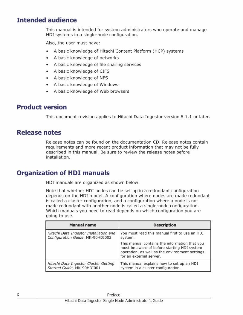
Intended audienceThis manual is intended for system administrators who operate and manageHDI systems in a single-node configuration.
Also, the user must have:
• A basic knowledge of Hitachi Content Platform (HCP) systems
• A basic knowledge of networks
• A basic knowledge of file sharing services
• A basic knowledge of CIFS
• A basic knowledge of NFS
• A basic knowledge of Windows
• A basic knowledge of Web browsers
Product versionThis document revision applies to Hitachi Data Ingestor version 5.1.1 or later.
Release notesRelease notes can be found on the documentation CD. Release notes containrequirements and more recent product information that may not be fullydescribed in this manual. Be sure to review the release notes beforeinstallation.
Organization of HDI manualsHDI manuals are organized as shown below.
Note that whether HDI nodes can be set up in a redundant configurationdepends on the HDI model. A configuration where nodes are made redundantis called a cluster configuration, and a configuration where a node is notmade redundant with another node is called a single-node configuration.Which manuals you need to read depends on which configuration you aregoing to use.
Manual name Description
Hitachi Data Ingestor Installation andConfiguration Guide, MK-90HDI002
You must read this manual first to use an HDIsystem.
This manual contains the information that youmust be aware of before starting HDI systemoperation, as well as the environment settingsfor an external server.
Hitachi Data Ingestor Cluster GettingStarted Guide, MK-90HDI001
This manual explains how to set up an HDIsystem in a cluster configuration.
x PrefaceHitachi Data Ingestor Single Node Administrator's Guide

Manual name Description
Hitachi Data Ingestor ClusterAdministrator's Guide, MK-90HDI038
This manual provides procedures for using HDIsystems in a cluster configuration, as well asprovides GUI references.
Hitachi Data Ingestor ClusterTroubleshooting Guide, MK-90HDI029
This manual provides troubleshootinginformation for HDI systems in a clusterconfiguration.
Hitachi Data Ingestor Single NodeGetting Started Guide, MK-90HDI028
This manual explains how to set up an HDIsystem in a single-node configuration.
Hitachi Data Ingestor Single NodeAdministrator's Guide (This manual)
This manual explains the procedures for usingHDI systems in a single-node configuration, aswell as provides GUI references.
Hitachi Data Ingestor Single NodeTroubleshooting Guide, MK-90HDI030
This manual provides troubleshootinginformation for HDI systems in a single-nodeconfiguration.
Hitachi Data Ingestor CLIAdministrator's Guide, MK-90HDI034
This manual describes the syntax of thecommands that can be used for HDI systems ina cluster configuration or a single-nodeconfiguration.
Hitachi Data Ingestor API References,MK-90HDI026
This manual explains how to use the API for HDIsystems in a cluster configuration or a single-node configuration.
Hitachi Data Ingestor Error Codes,MK-90HDI005
This manual contains messages for HDI systemsin a cluster configuration or a single-nodeconfiguration.
Hitachi Data Ingestor File SystemProtocols (CIFS/NFS) Administrator'sGuide, MK-90HDI035
This manual contains the things to keep in mindbefore using the CIFS or NFS service of an HDIsystem in a cluster configuration or a single-node configuration from a CIFS or NFS client.
The Cluster Administrator's Guide and the Single Node Administrator's Guideare available in HTML and PDF formats. All other manuals are available inonly PDF format.
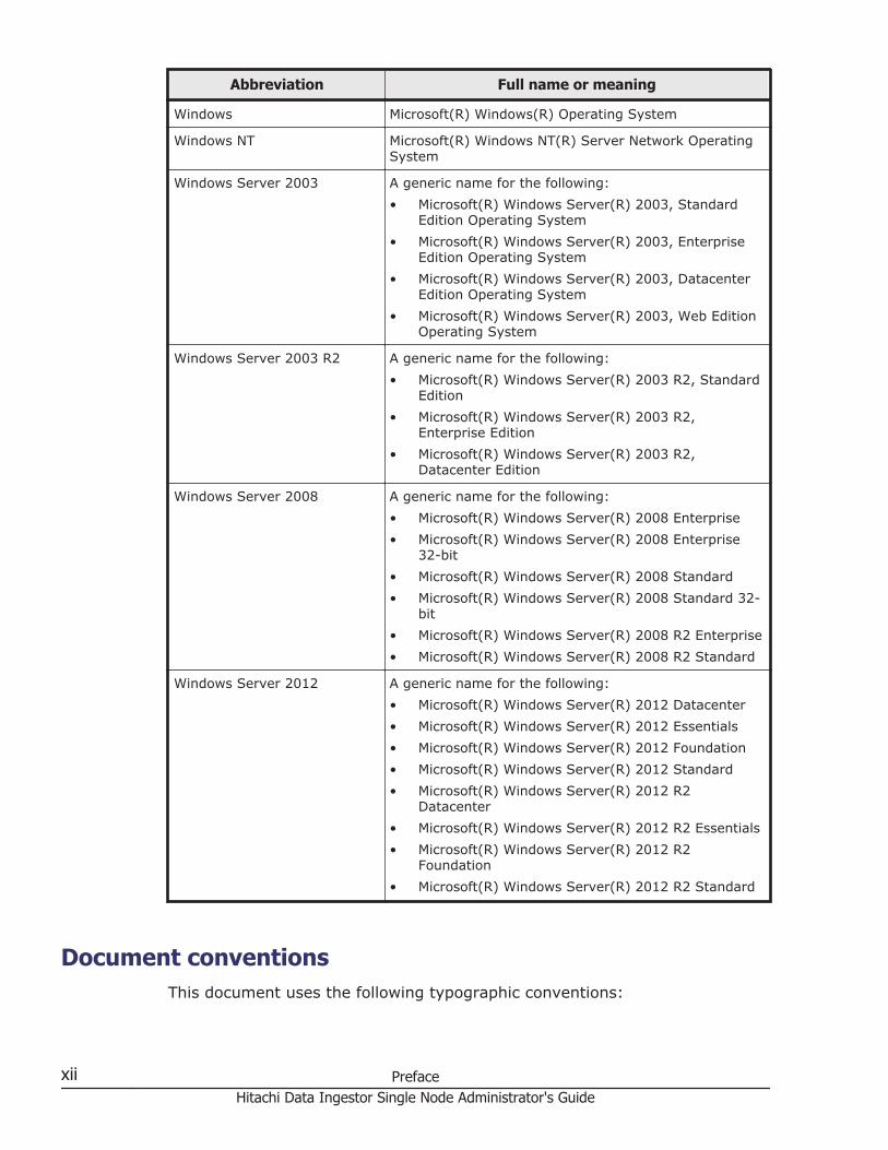
Abbreviation conventionsThis manual uses the following abbreviations for product names:
Abbreviation Full name or meaning
Active Directory Active Directory(R)
Dynamic Provisioning Hitachi Dynamic Provisioning
Dynamic Tiering Hitachi Dynamic Tiering
HCP Hitachi Content Platform
HDI Hitachi Data Ingestor
Internet Explorer Windows(R) Internet Explorer(R)
Preface xiHitachi Data Ingestor Single Node Administrator's Guide
Abbreviation Full name or meaning
Windows Microsoft(R) Windows(R) Operating System
Windows NT Microsoft(R) Windows NT(R) Server Network OperatingSystem
Windows Server 2003 A generic name for the following:
• Microsoft(R) Windows Server(R) 2003, StandardEdition Operating System
• Microsoft(R) Windows Server(R) 2003, EnterpriseEdition Operating System
• Microsoft(R) Windows Server(R) 2003, DatacenterEdition Operating System
• Microsoft(R) Windows Server(R) 2003, Web EditionOperating System
Windows Server 2003 R2 A generic name for the following:
• Microsoft(R) Windows Server(R) 2003 R2, StandardEdition
• Microsoft(R) Windows Server(R) 2003 R2,Enterprise Edition
• Microsoft(R) Windows Server(R) 2003 R2,Datacenter Edition
Windows Server 2008 A generic name for the following:
• Microsoft(R) Windows Server(R) 2008 Enterprise
• Microsoft(R) Windows Server(R) 2008 Enterprise32-bit
• Microsoft(R) Windows Server(R) 2008 Standard
• Microsoft(R) Windows Server(R) 2008 Standard 32-bit
• Microsoft(R) Windows Server(R) 2008 R2 Enterprise
• Microsoft(R) Windows Server(R) 2008 R2 Standard
Windows Server 2012 A generic name for the following:
• Microsoft(R) Windows Server(R) 2012 Datacenter
• Microsoft(R) Windows Server(R) 2012 Essentials
• Microsoft(R) Windows Server(R) 2012 Foundation
• Microsoft(R) Windows Server(R) 2012 Standard
• Microsoft(R) Windows Server(R) 2012 R2Datacenter
• Microsoft(R) Windows Server(R) 2012 R2 Essentials
• Microsoft(R) Windows Server(R) 2012 R2Foundation
• Microsoft(R) Windows Server(R) 2012 R2 Standard
Document conventionsThis document uses the following typographic conventions:
xii PrefaceHitachi Data Ingestor Single Node Administrator's Guide

Convention Description
Bold Indicates text on a window, other than the window title,including menus, menu options, buttons, fields, and labels.Example: Click OK.
Italic Indicates a variable, which is a placeholder for actual textprovided by the user or system. Example: copy source-filetarget-file
Note: Angled brackets (< >) are also used to indicatevariables.
screen/code Indicates text that is displayed on screen or entered by theuser. Example: # pairdisplay -g oradb
< > angled brackets Indicates a variable, which is a placeholder for actual textprovided by the user or system. Example: # pairdisplay-g <group>Note: Italic font is also used to indicate variables.
[ ] square brackets Indicates optional values. Example: [ a | b ] indicatesthat you can choose a, b, or nothing.
This document uses the following icons to draw attention to information:
Icon Label Description
Note Calls attention to important and/oradditional information.
Tip Provides helpful information, guidelines, orsuggestions for performing tasks moreeffectively.
Convention for storage capacity valuesStorage capacity values (e.g., drive capacity) are calculated based on thefollowing values:
Capacity Unit Physical Value Logical Value
1 KB 1,000 bytes 1,024 (210) bytes
1 MB 1,000 KB or 1,0002 bytes 1,024 KB or 1,0242 bytes
1 GB 1,000 MB or 1,0003 bytes 1,024 MB or 1,0243 bytes
1 TB 1,000 GB or 1,0004 bytes 1,024 GB or 1,0244 bytes
1 PB 1,000 TB or 1,0005 bytes 1,024 TB or 1,0245 bytes
1 EB 1,000 PB or 1,0006 bytes 1,024 PB or 1,0246 bytes
1 block - 512 bytes
Preface xiiiHitachi Data Ingestor Single Node Administrator's Guide
Getting helpThe Hitachi Data Systems customer support staff is available 24 hours a day,seven days a week. If you need technical support, log on to the Hitachi DataSystems Portal for contact information: https://portal.hds.com
CommentsPlease send us your comments on this document: [email protected] the document title, number, and revision, and refer to specificsection(s) and paragraph(s) whenever possible.
Thank you! (All comments become the property of Hitachi Data SystemsCorporation.)
xiv PrefaceHitachi Data Ingestor Single Node Administrator's Guide
1Logging on
This chapter describes how to log on the system.
□ Logging on to the system
Logging on 1-1Hitachi Data Ingestor Single Node Administrator's Guide
Logging on to the systemA system administrator can operate and manage a Hitachi Data Ingestor(HDI) system from a Web browser by logging on to the system.
To log on to the system
1. If you are using UPnP, click the HDI icon in Other Devices, whichappears in the network list in the management console.If you are not using UPnP, enter the URL in your web browser's addressbar, in the following format:https://HDI-IP-address-or-host-name/admin/The Login window appears.
2. Specify a user ID and the password in the Login window, and then clickLogin.The main window is displayed.
Note:
• If you are accessing the GUI for the first time, use the followingaccount to log on.User ID: adminPassword: chang3me! (default)
When you access the GUI for the first time, the Change UserPassword dialog box is displayed (Change User Password dialog boxon page C-29). Be sure to change the password to preventunpermitted access.
• The user ID and password here are shared with the HDI APIadministrator account. If the password is changed from the API, usethe new password.
1-2 Logging onHitachi Data Ingestor Single Node Administrator's Guide
2Managing system administrator
accounts
This chapter describes how to manage system administrator accounts.
□ Changing an account password
□ Changing account security settings
Managing system administrator accounts 2-1Hitachi Data Ingestor Single Node Administrator's Guide
Changing an account passwordA system administrator can change his or her own password.
GUI used for this operation
• Change User Password dialog box on page C-29
To change an account password
1. In the top-left corner of the GUI, select Action, select ChangePassword, and then select Change User Password.
2. In the Change User Password dialog box, specify the requiredinformation, and then click OK.
3. Make sure that the processing results are correct, and then click Close.
Note:
• Specify a new password that meets the conditions set in the LoginSecurity dialog box, such as the minimum number of characters and thecombination of the characters that can be used as a password.
• The password set here is required for the operation and management ofthe HDI system. Be sure not to forget this password.
• The password is shared with the HDI API administrator account. If thepassword is changed from the GUI, use the new password in the API.
• If the current password is lost, use the adminpasswd command to resetthe password and then specify a new password.
Changing account security settingsYou can change the session timeout time and the automatic account lockoutsettings. You can also change the conditions for specifying the systemadministrator's password to prevent discovery by a third party. Theseconditions include the minimum number of characters and the combination ofthe characters that can be specified for the system administrator's password.
GUI used for this operation
• Login Security dialog box on page C-31
To change the account security settings
1. In the top-left corner of the GUI, select Action, and then LoginSecurity.
2. In the Login Security dialog box, specify the required information, andthen click OK.
3. Make sure that the processing results are correct, and then click Close.
2-2 Managing system administrator accountsHitachi Data Ingestor Single Node Administrator's Guide
3Managing shared directories
This chapter describes how to manage shared directories.
□ Creating a shared directory
□ Sharing HCP data migrated from HDI as read-only
□ Changing the policy and schedule for migrating data to HCP
□ Setting conditions for preventing certain files from turning into stub files
□ Expanding the capacity of a file system
□ Importing data from another file server
Managing shared directories 3-1Hitachi Data Ingestor Single Node Administrator's Guide

Creating a shared directoryThis section explains how to create a shared directory.
GUI used for this operation
• Create File System dialog box on page C-193
To create a shared directory
1. In the top-left corner of the GUI, choose the Resources tab.
2. In the General Tasks area, click Create File System.
3. In the Create File System dialog box, specify a file system name, howto link to the HCP system, the access protocols to be used (CIFS, NFS, orboth), the capacity, and other options.Specify File system or Subtree for Namespace type, and then specifyhow to share the HCP data for Content sharing. If you are onlymigrating data to the HCP system and you are not using HCP datamigrated from other HDI systems, select Off for Content sharing. If youspecify File system for Namespace type, also specify the quota to beallocated to the migration-destination namespace. To share the HCP datawith end users of other HDI systems (by creating a home-directory-roaming file system), select Home directory for Content sharing, andthen specify the information about the migration-destination namespace.When you create a home-directory-roaming file system, you must specifyFile system for Namespace type and specify CIFS for the accessprotocol.
Note: If a file system is linked to the HCP system at the share level, youcannot use the Create File System dialog box to create a share orallocate the namespace. After creating the file system, use the AddShare dialog box to add the file share directly below the mount point,and then allocate the namespace to the file share.You can also enable single instancing to eliminate duplicate data and savecapacity. Single instancing can be enabled by clicking the Enable singleinstancing. By default, single instancing is enabled on files that are morethan 128 KB in size and have not been changed for one week or more.After creating the shared directory, change the setting as necessary in theTask Management dialog box (see Task Management dialog box onpage C-4). If execution of the single instancing task takes too muchtime after system operation starts, use the arcfilterpolicysetcommand to set the conditions for excluding files from the singleinstancing targets (filtering policy). However, if you specify Homedirectory for Content sharing, you cannot enable single instancing.Enable Enable the WORM function if you want to apply WORM whichkeeps files from being deleted for a specific period of time andautomatically sets files that are not accessed for a specific period of timeas read-only. However, if you specify Home directory for Contentsharing, you cannot enable the WORM functionality.
3-2 Managing shared directoriesHitachi Data Ingestor Single Node Administrator's Guide

To use version management and allow clients to view the past data as ofthe time the data was migrated to the HCP system, enable Use fileversion restore and specify the period of time during which the pastdata is to be retained.To use CIFS bypass traverse checking, enable CIFS bypass traversechecking. However, if you specify Home directory for Contentsharing, you cannot enable CIFS bypass traverse checking.
4. Click OK.
5. Verify the information displayed in the confirmation dialog box, and thenclick Apply.
6. Make sure that the processing results are correct, and then click Close.
Sharing HCP data migrated from HDI as read-onlyThis section describes sharing HCP data migrated from HDI as read-only.
GUI used for this operation
• Create File System dialog box on page C-193
To share HCP data migrated from HDI as read-only
1. In the top-left corner of the GUI, choose the Resources tab.
2. In the General Tasks area, click Create File System.
3. In the Create File System dialog box, specify a file system name, howto link to the HCP system, the access protocols to be used (CIFS, NFS, orboth), and the capacity.
Note: If a file system is linked to the HCP system at the share level, youcannot use the Create File System dialog box to create a share orallocate the namespace. After creating the file system, use the AddShare dialog box to add the file share directly below the mount point,and then allocate the namespace to the file share.
4. Select On for Content sharing.
5. If you select File System for Namespace type, specify the HCPnamespace information that refers to the data.Specify the system information for the HCP namespace whose data youwant to show and specify a namespace-access account.If you are using the replication functionality in the HCP system, alsospecify the system information for the replica HCP system.Click Test Connection to check whether you can connect to the HCP.
6. Click OK.
7. Verify the information displayed in the confirmation dialog box, and thenclick Apply.
8. Make sure that the processing results are correct, and then click Close.
Managing shared directories 3-3Hitachi Data Ingestor Single Node Administrator's Guide
Changing the policy and schedule for migrating data to HCPThis section explains how to change the policy and schedule for migratingdata to the HCP system.
GUI used for this operation
• Task Management dialog box on page C-4
To change a migration policy
1. In the top-left corner of the GUI, select Action, and then Manage Tasksand Policies.
2.In the Task List page in the Task Management dialog box, click (Edit) for a task.
3. In 1. Policy Name in the Edit Policy page in the Task Managementdialog box, change the policy description as necessary, and click Next.
4. Change the migration condition in 2. Criteria in the Edit Policy page, asnecessary.
5. Click Confirm.
To change a migration schedule
1. In the top-left corner of the GUI, select Action, and then Manage Tasksand Policies.
2.In the Task List page in the Task Management dialog box, click (Start) for a task.
3. On the Setup Schedule page in the Task Management dialog box,specify the required information.
4. Click Confirm.
Setting conditions for preventing certain files from turninginto stub files
This section explains how to set conditions (cache resident policies) so thatcertain files are not turned into stub files when the data in the file system ismigrated to the HCP system.
After you set conditions for preventing certain files from turning into stubfiles, file data that satisfies the conditions is always retained in the HDIsystem (cache residency). This causes the access time for these files to beshorter than for stub files.
GUI used for this operation
• file-system-name window on page C-53
• Add Cache Resident Policy dialog box on page C-212
3-4 Managing shared directoriesHitachi Data Ingestor Single Node Administrator's Guide
To set conditions for preventing certain files from turning into stubfiles
1. In the top-left corner of the GUI, choose the Resources tab.
2. In a tree on the left side of the GUI, select the triangle icon to the left ofthe host-name.
3. In a tree on the left side of the GUI, select the triangle icon to the left ofFile Systems, and then click a file system name.
4. In the file-system-name window, click the Cache Resident Policy tab.
5. In the Cache Resident Policy tab, click the Add.
6. In the Add Cache Resident Policy dialog box, specify the necessaryinformation.
Tip: Only files that meet all the conditions set for a policy are preventedfrom being turned into stub files. If multiple policies are set up, a file isnot turned into a stub file if all the conditions in at least one of thepolicies are met.
7. Click OK.
8. Verify the information displayed in the confirmation dialog box, and thenclick Apply.
9. Make sure that the processing results are correct, and then click Close.
After cache resident policies are set up, tasks for suppressing or recallingstub files are executed everyday at midnight to prevent the files that satisfythe specified conditions from turning into stub files.
Expanding the capacity of a file systemThis section explains how to expand the capacity of a file system in which ashared directory was created.
If you want to expand the capacity of a volume group used by a file system,you need to increase the number of disks. For details about how to increasethe number of disks, see Increasing the number of disks on page 6-2.
GUI used for this operation
• File Systems window on page C-49
• Edit File System dialog box on page C-204
To expand the capacity of a file system
1. In the top-left corner of the GUI, choose the Resources tab.
2. In a tree on the left side of the GUI, select the triangle icon to the left ofthe host-name, and then click File Systems.
3. In the File Systems window, select the file system, and then click Edit.
4. In the Edit File System dialog box, specify the size in Allocatecapacity.
Managing shared directories 3-5Hitachi Data Ingestor Single Node Administrator's Guide

5. Click OK.
6. Verify the information displayed in the confirmation dialog box, and thenclick Apply.
7. Make sure that the processing results are correct, and then click Close.
Importing data from another file serverThis section describes how to use GUIs to import file shares data that is usedin another file server to the HDI system. You can import data from multiplefile servers at the same time. A maximum of 20 file shares can be importedat the same time per HDI system. The way of importing data depends on theprotocol being used. If you use the CIFS protocol, see Importing data fromanother file server by using the CIFS protocol on page 3-6. If you use theNFS protocol, see Importing data from another file server by using the NFSprotocol on page 3-10. If the share type of the import-source file serverdiffers from the protocol used for importing data, information including theattribute might not be imported correctly. Use the same protocol as the sharetype when importing data.
Note: To set capacity limitations for each file share, user, or group,command settings are required when an importation starts. Therefore, werecommend you to use commands for importing data if you want to setcapacity limitation. For details about how to use commands for importingdata from another file server, see the Cluster Administrator's Guide.
Importing data from another file server by using the CIFS protocolThis section describes how to import data from another file server by usingthe CIFS protocol.
Before importing data, you must set the configuration definitions of the CIFSservice. Only files that are in non-WORM file system and are accessed byCIFS clients can be imported. The directory path of each file must be no morethan 4,095 bytes including the file name.
The following information and objects are not imported:
• File system attributes such as quota and share settings
• Symbolic links
• SACL (System ACL) and quota information for files and directories
• Encryption, compression, and non-indexed attributes for files anddirectories (The settings are removed.)
• Accounts that are not registered on the domain controller and accountsother than Everyone, CREATOR_OWNER, or CREATOR_GROUP (when domainauthentication is used)
• The directories and files of the followingnames: .history, .snaps, .arc, .system_gi, .system_reorganize, .backupdates, .temp_backupdates, lost+found, .lost+found
3-6 Managing shared directoriesHitachi Data Ingestor Single Node Administrator's Guide

System directories that are used by the server and that are in the import-source CIFS shares sometimes fail to be imported. If this happens, revise theowner accounts as well as any other accounts for which file accesspermissions for the directories that failed to be imported are set, and thenperform the importation again.
No more than 700 ACEs set for files and directories can be imported. Theimported files have archive attributes as DOS attributes. Also, the attributesfor NTFS ACL are converted into the corresponding attributes for AdvancedACL. For details about correspondence between NTFS ACL and Advanced ACLattributes, see the File System Protocols (CIFS/NFS) Administrator's Guide.
Before importation, download the Microsoft Visual C++ 2010 RedistributablePackage (x86) from Microsoft Download Center, and then install it on theimport-source file server.
For details about the user mapping method used when data is imported, seeIdentifying users by user mapping on page 4-8.
GUI used for this operation
• Import Files dialog box on page C-21
• List of RAS Information page on page C-32
• Shares window on page C-46
• Local Users dialog box on page C-75
• DNS, NIS, LDAP Setup page on page C-106
• Create File System dialog box on page C-193
To import data from another file server by using the CIFS protocol
1. Create a data access account for importation.Create an account for accessing shared data in an external authenticationserver. Set up an account so that the account can access all data in theshares to be imported. Specify the account name using no more than 256characters and the password using no more than 128 characters. You canuse alphanumeric characters, sign characters except backslashes (\), andmulti-byte characters that are encoded in UTF-8.
2. If some of the import-source files are owned by local accounts, on theimport-source file server, verify the local accounts, and then create amapping file for using the accounts in the HDI system.For Microsoft(R) Windows Server(R), use the mapping generation tool(sidlist.exe) to create a mapping file. The mapping generation tool isstored at the following location on the HDI installation media.installation-media-drive:\tool\sidlistCopy sidlist.exe to a desired directory on the import-source file server,and then run it by specifying the absolute path of sidlist.exe and themapping file.Example for when sidlist.exe is stored in the tool directory on the Ddrive:
Managing shared directories 3-7Hitachi Data Ingestor Single Node Administrator's Guide
D:\>d:\tool\sidlist.exe >d:\tool\mappingfile.txt
Verify the character encoding of the mapping file, and then save the filein the UTF-8 format.The entries are output to a mapping file as follows:[MAPDEF]SID=account-SIDSRC_NAME=import-source-account-nameKIND=account-type (u (user) or g (group))DST_NAME=import-target-account-nameIf you want to use different account names in the HDI system than theones that have been used on the import-source file server, edit theDST_NAME for those accounts. If you use domain accounts, specify thenames in domain-name\account-name format.
For servers other than Microsoft(R) Windows Server(R), manually createa mapping file containing the above entries for each local account.Verify the character encoding of the mapping file (use UTF-8).
3. Connect the HDI system to the network in which the HDI system canaccess the import-source file server.
4. Perform the necessary settings depending on how the import-source fileswill be accessed.
When domain authentication is usedSet the same DNS, NIS, and LDAP information for the HDI system asthe one set for the import-source file server.Set the information so that the name resolution and userauthentication work when clients access the HDI system in the sameway as when clients access the import-source file server. Also set upuser and group mapping by the external authentication server.
When local authentication is usedRegister the local accounts that were used on the import-source fileserver to the HDI system.Register the users and groups by using the names for DST_NAME instep 2 and specifying desired UIDs and GIDs.
When both domain authentication and local authentication are usedPerform the settings necessary for both domain authentication andlocal authentication.
5. Create and share the import-target file system in the HDI system.Note that this step is unnecessary if the import-target file system and fileshare have already been created.Create a non-WORM file system.In addition, set information about the namespace and a migrationschedule. Content sharing must be set to off.If you want to migrate data that is stored in the file system and updatedduring an importation to an HCP, configure settings to periodicallymigrate the data. However, if data migration starts during an importation,
3-8 Managing shared directoriesHitachi Data Ingestor Single Node Administrator's Guide
importation of all data is temporarily stopped, and then the importationmethod is changed to on-demand. This increases the time needed forimporting data. To reduce the time needed for importing data, set amigration schedule in step 18 after the importation is completed.Do not create any files or directories in the import-target file system untila importation is started in step 14. If a file or directory path is the sameas one in the import-source file system, the file or directorycorresponding to that path in the import-source file system is notimported.
6. In the Shares window, select the shared directory created in step 5, andthen click Import Files.
7. In the Import Files dialog box, specify the necessary information, andthen click Show Plan.
8. Make sure that the information displayed in the confirmation dialog box iscorrect, and then click Start Scan.Make sure that verification of the import-source files has started, and, ifnecessary, click Close.
9. In the top-left corner of the GUI, select the Tasks tab.The Import Files window appears.
10. In the Import Files window, check the status of the defined tasks.Make sure that Status is Scan finished.
If the Caution icon ( ) is displayed, an error occurred during verification,or some files could not be recognized as verification targets. Click thetask name, and display the Import Files dialog box. In the dialog box,click Display Scan Failure List or Display Read Failure List, andcheck the details about the error. Also, take any necessary action.
11. Notify clients who are using the import-source file server of theimportation schedule.
12. Set shares in the import-source file server as read-only.If an import-source file or directory is updated after the import starts, thefile or directory might not be properly imported.
13. Use MMC (Microsoft Management Console) (or some other similar tool) todisconnect the session connected to the import-source file server.For details about how to disconnect sessions, see the documentation forthe import-source file server.
14. In the Import Files window, select a task, and then click Start Import.
15. Make sure that the information displayed in the confirmation dialog box iscorrect, and then click Apply.
16. Inform clients that they can start accessing shares in the HDI system.Clients can access the shares in the HDI system during data importation.To check the progress of the import, from the Tasks tab, check theImport Files window. In the Import Files window, Import finished isdisplayed for Status if the import is completed.
17. In the Import Files window, check the results of the import.
Managing shared directories 3-9Hitachi Data Ingestor Single Node Administrator's Guide
If the Caution icon ( ) is displayed, an error occurred during the import,or some files could not be recognized as import sources. Click the taskname, and display the Import Files dialog box. In the dialog box, clickDisplay Import Failure List or Display Read Failure List, and checkthe details about the error.If files or directories are moved while a importation is being performed,those files might not have been imported. Confirm that all the files wereimported.If importation failed for some files, take action according to the recoveryprocedure described in the Single Node Troubleshooting Guide.If no files failed, but the number of import-source files differs from thenumber of files that were successfully imported, redo this procedure fromstep 14. The files that were not imported will be imported.If a node failure occurs or the file system capacity is insufficient whileimporting data from another file server, the import process might fail. Ifthis happens, a message is still output to prompt users to import dataagain even after an all-file import is performed again. Run thedatamigratestatus command with the --incompletionlist option toverify that the displayed files are all imported. If the files have beenimported, no action is necessary. If some files have not been imported,take action by, for example, manually copying the files one-by-one.
18. Set a migration schedule.Configure this setting if the schedule is not set in step 5. If a migrationschedule is set in step 5 and migration has never been performed,execute the arcmodectl command with the --init-migration enableoption specified to enable the initial mode. If 1,000,000 or more files areto be imported, execute the arcmodectl command with the --init-migration enable and -t repeat options specified to enable initial modeevery time a task is executed. If you specify the -t repeat option, whenthe number of files to be migrated drops below 1,000,000, disable initialmode.
19. Remove the import-source file server.
If a failure occurred during data importation, take action according to therecovery procedure described in the Single Node Troubleshooting Guide.
Importing data from another file server by using the NFS protocolThis section describes how to import data from another file server by usingthe NFS protocol.
Before importing data, you must set the configuration definitions of the NFSservice on the node. Only files that are in non-WORM file systems and areaccessed by NFS clients can be imported. The directory path of each file mustbe no more than 4,095 characters, including the file name.
The following information and objects are not imported:
• Quota information and ACL for files and directories
• File system attributes such as quota and share settings
3-10 Managing shared directoriesHitachi Data Ingestor Single Node Administrator's Guide

• Socket files
• The directories and files of the followingnames: .history, .snaps, .arc, .system_gi, .system_reorganize, .backupdates, .temp_backupdates, lost+found, .lost+found
GUI used for this operation
• Import Files dialog box on page C-21
• List of RAS Information page on page C-32
• Shares window on page C-46
• DNS, NIS, LDAP Setup page on page C-106
• Create File System dialog box on page C-193
To import data from another file server by using the NFS protocol
1. Connect the HDI system to the network in which the HDI system canaccess the import-source file server.
2. Set the same DNS, NIS, and LDAP information for the HDI system as setfor the import-source file server.Configure the settings so that name resolution and user authenticationused when a client accesses to the HDI system will operate in the sameway as when a client accesses the import-source file server.
3. Configure the shared directory on the import-source file server so that thedirectory can be accessed from the HDI system.
¢ Set the HDI IP address as a client that can access the shareddirectory.
¢ Set the directory as read-only, and enable clients to access thedirectory by using the root permissions that clients start with.
4. Create and share the import-target file system in the HDI system.Note that this step is unnecessary if the import-target file system and fileshare have already been created.Create a non-WORM file system.In addition, set information about the namespace and a migrationschedule. Content sharing must be set to off.If you want to migrate data that is stored in the file system and updatedduring an importation to an HCP, configure settings to periodicallymigrate the data. However, if data migration starts during an importation,importation of all data is temporarily stopped, and then the importationmethod is changed to on-demand. This increases the time needed forimporting data. To reduce the time needed for importing data, set amigration schedule in step 16 after the importation is completed.Do not create any files or directories in the import-target file system untilan import is started in step 12. If a file or directory path is the same asone in the import-source file system, the file or directory corresponding tothat path in the import-source file system is not imported.
Managing shared directories 3-11Hitachi Data Ingestor Single Node Administrator's Guide

5. In the Shares window, select the shared directory created in step 4, andthen click Import Files.
6. In the Import Files dialog box, specify the necessary information, andthen click Show Plan.
7. Make sure that the information displayed in the confirmation dialog box iscorrect, and then click Start Scan.Make sure that verification of the import-source files has started, and, ifnecessary, click Close.
8. In the top-left corner of the GUI, select the Tasks tab.The Import Files window appears.
9. In the Import Files window, check the status of the defined tasks.Make sure that Status is Scan finished.
If the Caution icon ( ) is displayed, an error occurred during verification,or some files could not be recognized as verification targets. Click thetask name, and display the Import Files dialog box. In the dialog box,click Display Scan Failure List or Display Read Failure List and checkthe details about the error. Also, take any necessary action.
10. Notify clients who are using the import-source file server of theimportation schedule.
11. Set shares in the import-source file server as read-only.If an import-source file or directory is updated after the import starts, thefile or directory might not be properly imported.
12. In the Import Files window, select a task, and then click Start Import.
13. Make sure that the information displayed in the confirmation dialog box iscorrect, and then click Apply.
14. Inform clients that they can start accessing shares in the HDI system.Clients can access the shares in the HDI system during data importation.To check the progress of the import, from the Tasks tab, check theImport Files window. In the Import Files window, Import finished isdisplayed for Status if the import is completed.
15. In the Import Files window, check the results of the import.
If the Caution icon ( ) is displayed, an error occurred during the import,or some files could not be recognized as import sources. Click the taskname, and display the Import Files dialog box. In the dialog box, clickDisplay Import Failure List or Display Read Failure List, and checkthe details about the error.If files or directories are moved while a importation is being performed,those files might not have been imported. Confirm that all the files wereimported.If importation failed for some files, take action according to the recoveryprocedure described in the Single Node Troubleshooting Guide.If no files failed, but the number of import-source files differs from thenumber of files that were successfully imported, redo this procedure fromstep 12. The files that were not imported will be imported.
3-12 Managing shared directoriesHitachi Data Ingestor Single Node Administrator's Guide

If a node failure occurs or the file system capacity is insufficient whileimporting data from another file server, the import process might fail. Ifthis happens, a message is still output to prompt users to import dataagain even after an all-file import is performed again. Run thedatamigratestatus command with the --incompletionlist option toverify that the displayed files are all imported. If the files have beenimported, no action is necessary. If some files have not been imported,take action by, for example, manually copying the files one-by-one. Notethat, if hard links for which different subtree quotas are set have not beenimported to the import source and import target, check, and if necessary,revise the quota settings, and then create hard links for each.
16. Set a migration schedule.Configure this setting if the schedule is not set in step 4. If a migrationschedule is set in step 4 and migration has never been performed,execute the arcmodectl command with the --init-migration enableoption specified to enable the initial mode. If 1,000,000 or more files areto be imported, execute the arcmodectl command with the --init-migration enable and -t repeat options specified to enable initial modeevery time a task is executed. If you specify the -t repeat option, whenthe number of files to be migrated drops below 1,000,000, disable initialmode.
17. Remove the import-source file server.
If a failure occurred during data importation, take action according to therecovery procedure described in the Single Node Troubleshooting Guide.
Managing shared directories 3-13Hitachi Data Ingestor Single Node Administrator's Guide

3-14 Managing shared directoriesHitachi Data Ingestor Single Node Administrator's Guide
4Setting up the access environment from
clients
This chapter describes how to set up the HDI system regarding the accessenvironment from clients that use shared directories.
□ Setting up the access environment from CIFS clients
□ Identifying users by user mapping
□ Collecting CIFS client access logs
□ Setting up the access environment from NFS clients
Setting up the access environment from clients 4-1Hitachi Data Ingestor Single Node Administrator's Guide
Setting up the access environment from CIFS clientsThis section describes how CIFS client access environments are applied tosystems according to the network model that is used.
Joining a node to an Active Directory domainA node can join an Active Directory domain to allow users belonging to thesame domain or trusted domains to access HDI shared directories.
Prerequisites for joining a node to an Active Directory domain
Acquire the following Active Directory domain information that will be usedduring the joining procedure:
• DNS name and NetBIOS name of the domain that the node is joining
• Domain controller server name. Another name (alias) cannot be specified.
• Name and password of the domain controller user
• IP address of the DNS server used by the domain
Make sure that the DNS server used by the domain is configured as follows:
• IP addresses for the node and the corresponding host names have beenregistered.
• The SRV records required for deploying the Active Directory service havebeen registered.
• All the IP addresses registered for the host names of the domaincontrollers can be used to communicate with the node.
• An IP address is not dynamically added to the host name for the domaincontroller.
If all the following conditions are satisfied, edit the /etc/cifs/lmhosts fileon the Edit System File page in the Network & System Configurationdialog box so that the nodes can search for the domain controller of thedomain with which a trust relationship has been established:
• The domain to which the node belongs has a trust relationship withanother domain.
• Either the domain to which the node belongs or a domain with which thenode has a trust relationship is an NT domain.
• The node and a domain that has a trust relationship with the node existon different network segments.
In the HDI system, create a shared folder that can use the CIFS protocol.
GUI used for this operation
• host-name window on page C-44
• System Setup Menu page on page C-93
• DNS, NIS, LDAP Setup page on page C-106
4-2 Setting up the access environment from clientsHitachi Data Ingestor Single Node Administrator's Guide

• List of Services page on page C-121
• CIFS Service Management (Basic) page on page C-123
• Select Authentication Mode page on page C-138
• Active Directory Authentication page on page C-141
To join a node to an Active Directory domain
1. In the top-left corner of the GUI, choose the Dashboard tab.
2.
In the System Information panel, click .
3. From the host-name window, click Network & System Configuration inthe Settings area.
4. In the Network & System Configuration dialog box, select network inthe Setting Type drop-down list, and then click Display.
5. In the System Setup Menu page (Setting Type: network), click DNS,NIS, LDAP Setup.
6. In the DNS, NIS, LDAP Setup page, specify information about the DNSserver used for the Active Directory domain, and click OK.If a confirmation dialog box is displayed, click OK.
7. In the System Setup Menu page, click Close.
8. From the host-name window, click Access Protocol Configuration inthe Settings area.
9. In the List of Services page of the Access Protocol Configurationdialog box, select CIFS, and then click Modify Configuration.
10. In the CIFS Service Management (Basic) page, click ChangeAuthentication Mode.
11. In the Select Authentication Mode page, select Active Directoryauthentication from the options, and then click OK.
12. In the Active Directory Authentication page, specify the necessaryinformation, and then click OK.
13. On the CIFS Service Management (Basic) page, click OK.
14. On each page of CIFS Service Management, specify the necessaryinformation, and then click OK.Select the Setting Type drop-down list, and click Display for thenecessary information. If you change Setting Type, click OK afterspecifying information.When an Active Directory domain is joined, Hitachi Data Systemsrecommend that you use user mapping to manage user information. Fordetails about how to use user mapping, see Identifying users by usermapping on page 4-8.
15. Click End of Settings on the confirm settings page.
16. On the List of Services page, restart the CIFS service. Also restart theNFS, FTP, or SFTP service as needed.Inform any clients using the service of the temporary stoppage beforestarting. Select the target service and click Restart to restart the service.
Setting up the access environment from clients 4-3Hitachi Data Ingestor Single Node Administrator's Guide

For details about whether the NFS, FTP, and SFTP services need to berestarted, see Conditions that the NFS, FTP, and SFTP services need to berestarted on page 4-4.
17. Restart the node.
Notes on after joining a node to an Active Directory domain
• If the Active Directory authentication is set, make sure that the systemtimes of the domain controller, the HDI system, and CIFS clients are thesame. If there is a time difference of more than 5 minutes among thesesystems, authentication might fail when CIFS clients access the HDIsystem.
• After changing the Active Directory domain, if you immediately changethe settings to rejoin the nodes to their previous Active Directory domain,authentication of a CIFS client might result in an error even though theprocessing was successful. In this case, in the CIFS ServiceMaintenance page, click Rejoin Active Directory Domain to rejoin thenodes to the Active Directory domain.
• If you join the nodes to another Active Directory domain that has thesame name as the previous one, an unnecessary computer account mightremain in the previous Active Directory domain. Use the domain controllerof the previous Active Directory domain to delete the unnecessarycomputer account.
• When a user registered in a domain attempts to access the CIFS share ofan HDI system from a client machine that is not registered in the domain,user authentication might fail. In this case, use the CIFS ServiceMaintenance page to check whether the NetBIOS name of the ActiveDirectory domain has been set correctly.
• If Active Directory is used for user authentication, only usersauthenticated by Active Directory can access CIFS shares. Users locallyauthenticated by the HDI system cannot access CIFS shares.
Conditions that the NFS, FTP, and SFTP services need to be restarted
The NFS service needs to be restarted in the following cases.
• If you change the authentication mode from a mode other than ActiveDirectory to Active Directory
• If you change the Active Directory domain name or the server name forthe Active Directory domain controller
• When using an Active Directory domain controller and KDC servertogether, and a different name is set than that of the domain to which theKDC server using the NFS service belongs, or that of the KDC server
The FTP or SFTP service needs to be restarted in the following cases.
• If the FTP or SFTP service settings allow users authenticated with ActiveDirectory to log on, and the authentication type is changed from ActiveDirectory to another type or from another type to Active Directory.
4-4 Setting up the access environment from clientsHitachi Data Ingestor Single Node Administrator's Guide
Rejoining an Active Directory domainIf a domain controller failure or a domain configuration change occurs whileActive Directory is being joined, connection to the CIFS share might not bepossible. In this case, the node can join the Active Directory domain again torestore the connection to the CIFS share.
GUI used for this operation
• host-name window on page C-44
• List of Services page on page C-121
• CIFS Service Maintenance page on page C-158
To rejoin an Active Directory domain
1. In the top-left corner of the GUI, choose the Dashboard tab.
2.
In the System Information panel, click .
3. From the host-name window, click Access Protocol Configuration inthe Settings area.
4. In the List of Services page of the Access Protocol Configurationdialog box, select CIFS, and then click Service Maintenance.
5. In the CIFS Service Maintenance page, click Rejoin Active DirectoryDomain.The selected CIFS service is rejoined to the Active Directory domain.
Note: If an attempt to rejoin the Active Directory domain fails, manuallydelete any computer accounts remaining on the Active Directory domain,and try again.
Joining a node to an NT domainA node can join an NT domain to allow users belonging to the same domainor trusted domains to access HDI shared directories.
Prerequisites for joining a node to an NT domain
Acquire the following NT domain information that will be used during thejoining procedure:
• DNS name and NetBIOS name of the domain that the node is joining
• Domain controller server name. Another name (alias) cannot be specified.
• User name and password of the domain controller administrator
• IP address of the DNS server used by the domain
If all the following conditions are satisfied, edit the /etc/cifs/lmhosts fileon the Edit System File page in the Network & System Configurationdialog box so that the nodes can search for the domain controller of thedomain with which a trust relationship has been established:
Setting up the access environment from clients 4-5Hitachi Data Ingestor Single Node Administrator's Guide
• The domain to which the node belongs has a trust relationship withanother domain.
• Either the domain to which the node belongs or a domain with which thenode has a trust relationship is an NT domain.
• The node and a domain that has a trust relationship with the node existon different network segments.
Make sure that the network segment to which the node is connected does notcontain computers that are not servers and whose names are the same asthe domain controller server name specified in the NT DomainAuthentication page. When the nodes are connected to multiple networksegments (including VLANs), check the above condition for all the networksegments to be connected.
In the HDI system, create a shared folder that can use the CIFS protocol.
GUI used for this operation
• host-name window on page C-44
• List of Services page on page C-121
• CIFS Service Management (Basic) page on page C-123
• Select Authentication Mode page on page C-138
• NT Domain Authentication page on page C-140
To join a node to an NT domain
1. In the top-left corner of the GUI, choose the Dashboard tab.
2.
In the System Information panel, click .
3. From the host-name window, click Access Protocol Configuration inthe Settings area.
4. In the List of Services page of the Access Protocol Configurationdialog box, select CIFS from the options, and then click ModifyConfiguration.
5. In the CIFS Service Management (Basic) page, click ChangeAuthentication Mode.
6. In the Select Authentication Mode page, select NT domainauthentication from the options, and then click OK.
7. On the NT Domain Authentication page, specify the necessaryinformation, and then click OK.
8. On the CIFS Service Management (Basic) page, click OK.
9. On each page of CIFS Service Management, specify the necessaryinformation, and then click OK.Select the Setting Type drop-down list, and click Display for thenecessary information. If you change Setting Type, click OK afterspecifying the information.
4-6 Setting up the access environment from clientsHitachi Data Ingestor Single Node Administrator's Guide

When an NT domain is joined, Hitachi Data Systems recommend that youuse user mapping to manage user information. For details about how touse user mapping, see Identifying users by user mapping on page 4-8.
10. Click End of Settings on the settings confirmation page.
11. In the List of Services page, restart the CIFS service. Also, restart theFTP or SFTP service as needed.Inform any clients using the service of the temporary stoppage beforestarting. Select the target service and click Restart to restart the service.The FTP or SFTP service needs to be restarted if the FTP or SFTP servicesettings allow users authenticated with Active Directory to log on, and theauthentication type is changed from Active Directory.
12. Restart the node.
Configuring a workgroupIn a workgroup, nodes authenticate users who access nodes.
GUI used for this operation
• host-name window on page C-44
• List of Users / Groups page on page C-75
• Add User page on page C-78
• Add Group page on page C-86
• List of Services page on page C-121
• CIFS Service Management (Basic) page on page C-123
• Select Authentication Mode page on page C-138
• Local Authentication page on page C-139
To configure a workgroup
1. In the top-left corner of the GUI, choose the Dashboard tab.
2.
In the System Information panel, click .
3. From the host-name window, click Access Protocol Configuration inthe Settings area.
4. In the List of Services page of the Access Protocol Configurationdialog box, select CIFS from the options, and then click ModifyConfiguration.
5. In the CIFS Service Management (Basic) page, click ChangeAuthentication Mode.
6. In the Select Authentication Mode page, select Local authenticationfrom the options, and then click OK.
7. In the Local Authentication page, specify the necessary information,and then click OK.
8. On the CIFS Service Management (Basic) page, click OK.
Setting up the access environment from clients 4-7Hitachi Data Ingestor Single Node Administrator's Guide
9. On each page of CIFS Service Management, specify the necessaryinformation, and then click OK.Select the Setting Type drop-down list, and click Display, for thenecessary information. If you change Setting Type, click OK afterspecifying the information.
10. Click End of Settings on the settings confirmation page.
11. In the List of Services page, restart the CIFS service. Also, restart theFTP or SFTP service as needed.Inform any clients using the service of the temporary stoppage beforestarting. Select the service to be restarted and click Restart to restartthe service. The FTP or SFTP service needs to be restarted if the FTP orSFTP service settings allow users authenticated with Active Directory tolog on, and the authentication type is changed from Active Directory.
12. Restart the node.
13. From the host-name window, click Local Users in the Settings area.
14. On the List of Users / Groups page (for List of users) of the LocalUsers dialog box, select List of groups from the drop-down list, andthen click Display.
15. On the List of Users / Groups page (for List of groups), click AddNew Group.
16. On the Add Group page, add groups that access shared directories onthe node, and then click OK.To enable the group to access CIFS shared directories, select Apply toCIFS ACL environment.
17. On the List of Users / Groups page (for List of groups), select Listof users from the drop-down list, and then click Display.
18. On the List of Users / Groups page (for List of users), click AddNew User.
19. On the Add User page, add users that access shared directories on thenode, and then click OK.To enable the user to access CIFS shared directories, select Apply toCIFS environment.
Identifying users by user mappingWhen user mapping is used, since the user ID and group ID are assigned forthe CIFS clients managed by the Active Directory domain and NT domain, theHDI system can identify users.
User-mapping methods
User mapping using RIDsWhen a CIFS client accesses the HDI file system, the RIDs (relativeidentifiers) comprising the SID are converted, and the user ID and groupID are automatically assigned.
4-8 Setting up the access environment from clientsHitachi Data Ingestor Single Node Administrator's Guide
User mapping using LDAPUser IDs and group IDs are assigned according to the user informationregistered in the LDAP server database. These can be registered manuallyin advance, or automatically in the LDAP server database when a CIFSclient accesses the HDI.
User mapping using Active Directory schemaWhen Active Directory authentication is used, correspondence fordifferent identify IDs between NFS clients and CIFS clients can bemanaged as a user attribute. User IDs and group IDs are assignedaccording to the user information already registered in the domaincontroller.
Prerequisites for user mapping
• To change the user mapping method that you use, you need to re-createthe file systems after you migrate the data by using Windows backupfunction.
• When a user ID or group ID is assigned, it can no longer be reused, evenif you delete the user information from the domain controller.
• Make sure that the user IDs and group IDs used for user mapping do notoverlap with those registered for the HDI system, NIS server, or userauthentication LDAP server.
• If the RID or LDAP method is used to automatically assign user IDs andgroup IDs, the range of used IDs is reserved. The ID range can only havethe maximum value changed.To prevent the ID range used for user mapping from becoming non-extensible due to overlap with IDs registered for the HDI system, NISserver, or user authentication LDAP server, Hitachi Data Systemsrecommend that numerical IDs larger than those used for user mappingnot be used for the HDI system, NIS server, or user authentication LDAPserver.
• When using LDAP user mapping, create a tree on the LDAP server thatcontains the user IDs and group IDs, before performing HDI settings.
GUI used for this operation
• host-name window on page C-44
• List of Services page on page C-121
• CIFS Service Management (Basic) page on page C-123
• CIFS Service Management (User mapping) page on page C-125
To use user mapping
1. In the top-left corner of the GUI, choose the Dashboard tab.
2.
In the System Information panel, click .
Setting up the access environment from clients 4-9Hitachi Data Ingestor Single Node Administrator's Guide
3. From the host-name window, click Access Protocol Configuration inthe Settings area.
4. In the List of Services page of the Access Protocol Configurationdialog box, select CIFS, and then click Modify Configuration.
5. Select User mapping from the Setting Type drop-down list on the CIFSService Management (Basic) page, and click Display.
6. On the CIFS Service Management (User mapping) page, specify thenecessary information, and click OK.
7. Click End of Settings on the settings confirmation page.
8. Restart the CIFS service.Inform any clients using the service of the temporary stoppage beforestarting. Select the target service and click the Restart to restart theservice.
Note:
• Even if a user registered by the domain controller is registered withthe same name as for the HDI, the NIS server, or the LDAP server foruser authentication, the user ID and group ID assigned by usermapping will be used when the user accesses a CIFS share.
• You can use commands to view information about users and groupsmapped by the RID method. For details about how to view usermapping information, see the CLI Administrator's Guide.
Collecting CIFS client access logsYou can specify when CIFS client access logs should be collected.
Specified settings are applied to the entire CIFS service. However, if eventsthat are recorded as the CIFS access log are specified for each CIFS share byusing the cifscreate command or the cifsedit command, the settings foreach CIFS share are given priority over the settings for the entire CIFSservice. When the settings for the CIFS service are changed, verify thesettings for each CIFS share as well as the settings for the entire CIFSservice.
GUI used for this operation
• host-name window on page C-44
• List of Services page on page C-121
• CIFS Service Management (Basic) page on page C-123
• CIFS Service Management (Security) page on page C-131
• Setting Events Logged to the CIFS Access Log page on page C-144
To collect CIFS client access logs
1. In the top-left corner of the GUI, choose the Dashboard tab.
4-10 Setting up the access environment from clientsHitachi Data Ingestor Single Node Administrator's Guide

2.
In the System Information panel, click .
3. From the host-name window, click Access Protocol Configuration inthe Settings area.
4. In the List of Services page of the Access Protocol Configurationdialog box, select CIFS from the options, and then click ModifyConfiguration.
5. Select Security from the Setting Type drop-down list in the CIFSService Management (Basic) page, and click Display.
6. In the CIFS Service Management (Security) page, select Use forCIFS access log, and then click Set Up in Events logged to the CIFSaccess log.
7. In the Setting Events Logged to the CIFS Access Log page, selectevents that you want to record as the CIFS access log, and then click OK.
8. Click OK on the CIFS Service Management (Security) page.
9. Click End of Settings on the settings confirmation page.
Setting up the access environment from NFS clientsThis section explains how to enable NFS clients to access shared directories.
If Kerberos authentication is used, set up an NTP server to synchronize thetimes of the HDI system and the NFS client hosts.
GUI used for this operation
• host-name window on page C-44
• List of Services page on page C-121
• NFS Service Management page on page C-150
To enable NFS clients to access shared directories
1. In the top-left corner of the GUI, choose the Dashboard tab.
2.
In the System Information panel, click .
3. From the host-name window, click Access Protocol Configuration inthe Settings area.
4. In the List of Services page of the Access Protocol Configurationdialog box, select NFS from the options, and then click ModifyConfiguration.
5. In the NFS Service Management page, specify the requiredinformation, and then click OK.
6. In the List of Services page, select NFS, and then click Restart torestart the NFS service.
Setting up the access environment from clients 4-11Hitachi Data Ingestor Single Node Administrator's Guide

4-12 Setting up the access environment from clientsHitachi Data Ingestor Single Node Administrator's Guide

5Showing previous data
This chapter describes how to show clients the previous data of files in shareddirectories.
□ Showing previous data on HCP
Showing previous data 5-1Hitachi Data Ingestor Single Node Administrator's Guide

Showing previous data on HCPThis section explains how to show clients previous data that was migrated tothe HCP system.
GUI used for this operation
• File Systems window on page C-49
• Edit File System dialog box on page C-204
To show previous data on HCP
1. In the top-left corner of the GUI, choose the Resources tab.
2. In a tree on the left side of the GUI, select the triangle icon to the left ofthe host-name, and then click File Systems.
3. In the File Systems window, select the target file system, and then clickEdit.
4. In the Edit File System dialog box, select the Yes check box for Use fileversion restore, and then specify the retention period for previous data.
5. Click OK.
6. Verify the information displayed in the confirmation dialog box, and thenclick Apply.
7. Make sure that the processing results are correct, and then click Close.
8. Change the CIFS client settings for the shared directory so that all filesand folders are displayed.This allows CIFS clients to view to the .history folder in the shareddirectory in which previous data is shown.
5-2 Showing previous dataHitachi Data Ingestor Single Node Administrator's Guide
6Managing disk capacity
This chapter describes how to manage disk capacity.
To manage disk capacity, you might need to use commands. See Setting upthe SSH environment to use commands on page 11-2 to set up a properenvironment.
□ Increasing the number of disks
□ Changing the use of disks
Managing disk capacity 6-1Hitachi Data Ingestor Single Node Administrator's Guide

Increasing the number of disksThis section describes how to increase the number of disks that can beassigned to a file system to create or expand a volume group that can beused for the file system. Work with maintenance personnel or the storagesystem administrator to perform this task.
Tip: A maximum of 32 MB is used as a management area per LU. Therefore,the total capacity of a volume group differs from the total capacity of internalhard disks or storage system's LUs.
For details about how to add internal hard disks to a node, see Addinginternal hard disks to a node on page 6-2. For details about how to addLUs to a running storage system, see Adding LUs to a running storage systemon page 6-3.
Adding internal hard disks to a nodeThis section describes how to add internal hard disks to a node to increasethe number of disks.
To add internal hard disk to a node
1. Notify clients of a temporary stoppage of the service.
2. Execute the nasshutdown command to stop the OS running on the node.
3. Add disks to the node.
4. Use the node power switch to turn on the node.For details about the node power switch, see Starting and forciblystopping a node OS on page H-2.
5. Execute the lumaplist command and then the hwstatus command tocheck the status of the internal hard disks.Make sure that the disks have been added and no problem has occurredon the disks.
6. From a browser, log on to the system.A dialog box appears that asks you whether to automatically assign theadded disks to a volume group.
7. Click Yes.The added disks are automatically assigned to an existing or createdvolume group.If there is a volume group with the same drive type as that of the disksadded to the internal hard disk, the disks are assigned to the volumegroup. For other cases, a volume group is created for each drive type witha different name (vg four-digit-number) from those of the existing volumegroups.
Tip: If you click No, you need to use the vgrcreate command to create avolume group to which the disks are to be assigned or to use thevgrexpand command to assign the disks to an existing volume group.
6-2 Managing disk capacityHitachi Data Ingestor Single Node Administrator's Guide
8. Make sure that the processing results are correct, and then click Close.
Adding LUs to a running storage systemThis section describes how to add LUs to a running storage system toincrease the number of disks.
Before adding LUs to a running storage system to increase thenumber of disks
If you are using the LUs of the target storage system on HDI for the firsttime, perform the following procedure first:
1. Ask the administrator of the storage system to set the host group and thepaths for the LUs on the storage system side.
2. If HDI and the storage system are not connected, work with theadministrator of the storage system to connect HDI and the storagesystem.
If you connected HDI and the storage system before configuring the settingson the storage system side, perform one of the following:
• Disconnect and then reconnect the FC cable that connects the node andthe storage system.
• Disable and then re-enable the port connected to the storage system onthe FC switch located between the node and the storage system.
• Restart the node.
To add LUs to a running storage system
1. Ask the storage system's administrator to create LUs to be used in theHDI system and to add the paths for the LUs.
2. Execute the lumaplist command to view the LU information.
If a problem occurs with the LU paths, contact the storage systemadministrator.
3. From a browser, log on to the system.A dialog box appears that asks you whether to automatically assign theadded LUs to a volume group.
4. Click Yes.The added LUs are automatically assigned to an existing or createdvolume group.If there is a volume group with the same drive type (same pool for virtualLUs) as that of the LUs added to the same storage system, the LUs areassigned to the volume group. For other cases, a volume group is createdfor each drive type (pool for virtual LUs) with a different name (vgfour-digit-number) from those of the existing volume groups.
Managing disk capacity 6-3Hitachi Data Ingestor Single Node Administrator's Guide
Tip: If you click No, you need to use the vgrcreate command to create avolume group to which the LUs are to be assigned or to use thevgrexpand command to assign the LUs to an existing volume group.
5. Make sure that the processing results are correct, and then click Close.
Changing the use of disksThis section explains how to perform the necessary tasks when changing theuse of disks for an HDI system.
Deleting a volume groupThis section explains how to delete a volume group. When using a storagesystem, perform the operation together with the storage systemadministrator.
To delete a volume group
1. Delete all file systems using the target volume group.
2. Execute the vgrdelete command to delete the target volume group.
3. When using a storage system, ask the storage administrator to delete theLU paths.Delete the paths to all the LUs that make up the volume group.
4. Execute the lumaplist command to view the LU information.
If a problem occurs with the LU paths, contact the storage systemadministrator.
Deleting LUs that are not being used by file systems from a volumegroup
This section explains how to delete LUs from a volume group when using astorage system. You can delete only LUs that are not being used by filesystems. Perform this operation together with the storage systemadministrator.
To delete LUs that are not being used by file systems from a volumegroup
1. Execute the lumaplist command with the -v option specified, and thenconfirm the name of the volume group assigned to the LU.
2. Execute the vgrrepair command with --list and --lu options specified,and then confirm that the LU is not used by the file system.
3. Ask the storage system administrator to delete the LU path.
4. Execute the vgrrepair command to repair the volume group.
5. Execute the lumaplist command to view the LU information.
6-4 Managing disk capacityHitachi Data Ingestor Single Node Administrator's Guide

If a problem occurs with the LU paths, contact the storage systemadministrator.
Managing disk capacity 6-5Hitachi Data Ingestor Single Node Administrator's Guide

6-6 Managing disk capacityHitachi Data Ingestor Single Node Administrator's Guide
7Protecting user data
This chapter describes how to set up virus scanning and back up and restoreuser data.
□ Setting up virus scanning
□ Backing up data to a tape device
□ Restoring data from a tape device
Protecting user data 7-1Hitachi Data Ingestor Single Node Administrator's Guide

Setting up virus scanningThis section explains how to set up virus scanning that is performed whenCIFS clients access files.
GUI used for this operation
• host-name window on page C-44
• List of Scanner Servers page on page C-167
• Add Scanner Server page on page C-170
• Scan Conditions page on page C-171
• Scanning software page on page C-177
To set up virus scanning
1. In the top-left corner of the GUI, choose the Dashboard tab.
2.
In the System Information panel, click .
3. From the host-name window, click Virus Scan Server Configuration inthe Settings area.
4. On the List of Scanner Servers page of the Virus Scan ServerConfiguration dialog box, click Scanning Software.
5. On the Scanning software page, select the desired software, and thenclick OK.
6. On the List of Scanner Servers page, click Add Server.
7. On the Add Scanner Server page, specify the IP address, domain name,or host name of the scan server, and a port number of the scan server,and then click Add.
8. On the List of Scanner Servers page, click Scan Conditions.
9. View the Scan Conditions page, change settings as necessary, and clickOK.
Note: Real-time scanning is not performed for the clients who are accessingthe CIFS share before scanning is enabled. In this case, restart the CIFSservice, or ask the clients to reconnect to the CIFS service.
Backing up data to a tape deviceThis section explains how to back up data to a tape device.
If either of the following conditions is met, backup processing might end withan error:
• The total size of the length of the directory and file names to be backedup at the same time exceeds 1 GB.
7-2 Protecting user dataHitachi Data Ingestor Single Node Administrator's Guide
• The total size of the length of the directory and file names in the directoryimmediately under the directories to be backed up at the same timeexceeds 1 GB.
When calculating the sum, add 1 byte as the delimiter between each directoryand file.
Make sure the total length of the names of the directories and files to bebacked up does not exceed 1 GB by reducing the number of directories andfiles to be backed up, or by adjusting the hierarchy.
To back up data to a tape device
1. Estimate the required backup media capacity.Estimate the required backup media capacity from the amount of data tobe backed up, and then prepare a tape device. For details on how toestimate the backup media capacity, see the Installation andConfiguration Guide.
2. Set up the operating environment for the backup management software.For details on how to set up an operating environment for the backupmanagement software, see Backup Restore, supplementary materialprovided with the HDI system.
Note: Some backup management software products might not workcorrectly if the length of the path for data to be backed up is too long.Before starting formal operations, perform a test to make sure thatbackup and restore operations are performed correctly.If the interruption for an offline backup is configured so that backupprocessing continues even if a file is modified or deleted during the offlinebackup, go to step 6. To view and change the interruption settings, usethe ndmpfsconfig command.
3. Stop the NFS, CIFS, FTP, SFTP, and TFTP services.
4. Use the cifsbackup command or the nfsbackup command to back up thefile share information, as necessary.For details about how to back up file share information, see the CLIAdministrator's Guide.
5. Unmount and then remount the file system.
6. Verify that the file system that you want to back up is mounted, and ifnot, mount it.
7. Restart the NDMP server if you performed any of the following operationsafter the last restart:
¢ Set or change the IP address or subnet mask of the node
¢ Set or change the IP address or host name of the gateway
¢ Add or change backup server information in the /etc/hosts file
8. Verify that the NDMP server is running normally.
Protecting user data 7-3Hitachi Data Ingestor Single Node Administrator's Guide

9. Record the file system attributes such as the ACL type and thepermissions and ACLs of all the directories above and for the directoryused as the base point for the backup.
10. Use backup management software to perform the backup operation.
11. If you stopped the NFS, CIFS, FTP, SFTP, and TFTP services in step 3,start the services.
Restoring data from a tape deviceThis section explains how to restore data from a tape device.
When restoring files by specifying each file, if you specify more than 10,000directories and files individually as restoration targets, restoration processingmight end with an error. Make sure that the total number of directories andfiles does not exceed 10,000 by reducing the number of directories and filesor by batch restoration of the data.
Before restoring data from backup media, use the arcrestore command torestore the HCP system data.
To restore data from a tape device
1. Set up the operating environment for the backup management software.For details on how to set up the operating environment for the backupmanagement software, see Backup Restore, supplementary materialprovided with the HDI system.
2. Prepare the restore-destination file system.For the restore-destination file system, specify a capacity that is 105% ormore of the size of the restore data and use the same ACL type as theone used when the data has been backed up. If you need to restorebackup data of the Classic ACL type to a file system of the Advanced ACLtype, you must take into account the amount of space required for ACLconversion. For details about migrating to a file system that uses theAdvanced ACL type, see the Installation and Configuration Guide.If you want to restore the data of the WORM file system, and the originalfile system can be used normally, restore the data to the original filesystem.The data of a file system that supported 64-bit inodes needs to berestored in a file system that supports 64-bit inodes. If you restore thedata in a file system that does not support 64-bit inodes, the number offiles might exceed the maximum number of files that can be created in afile system.To restore data to a file system that is different from the backup source,create a new file system. If you restore data in an existing file system,the number of files might exceed the maximum number of files that canbe created in a file system.
3. Prepare the restore-destination directory.Create the same directory hierarchy from the mount point to the parentdirectory of the restoration target, and set the same permissions for all
7-4 Protecting user dataHitachi Data Ingestor Single Node Administrator's Guide

the directories in the hierarchy as in the backup data. If the samedirectory hierarchy does not exist, directories from the mount point to theparent directory will automatically be created during the restore operationbut might be assigned different permissions or ACLs from those presentwhen a backup is performed.To restore data to a WORM file system, the structure of the directoriesand files in the file system must be the same as when the data wasbacked up.If you created a new file system, go to step 5.
4. Stop the NFS, CIFS, FTP, SFTP, and TFTP services, on the node thatcontains the file systems of the restore destination.
5. Verify that the file system that you want to back up is mounted with theread and write permissions enabled.If not mounted, mount it in that manner.
6. Restart the NDMP server if you performed any of the following operationsafter the last restart:
¢ Set or change the IP address or subnet mask of the node
¢ Set or change the IP address or host name of the gateway
¢ Add or change backup server information in the /etc/hosts file
7. Use backup management software to perform the restore operation.If data for multiple file systems exists in the data to be restored, restorethe data for each file system. If multiple directories and files with thesame relative paths exist within the selected data, the data might berestored to an unintended state.
Note: When the restore operation is performed for a file or directorywithout using the DAR function, the processing time increases dependingon the amount of backup data, not depending on the amount of data tobe restored.
8. If you stopped the NFS, CIFS, FTP, SFTP, and TFTP services in step 4,start the services.
9. Create a file share on the file system.
Protecting user data 7-5Hitachi Data Ingestor Single Node Administrator's Guide

7-6 Protecting user dataHitachi Data Ingestor Single Node Administrator's Guide

8Backing up system configuration
This chapter explains how to back up the system configuration.
□ Manually backing up the system configuration
□ Regularly backing up system configuration
Backing up system configuration 8-1Hitachi Data Ingestor Single Node Administrator's Guide
Manually backing up the system configurationThis section explains how to manually back up the system configurationwithin the system and download the system configuration file to a diskoutside of the system.
GUI used for this operation
• System Information panel on page C-39
• host-name window on page C-44
• Save System Settings Menu page on page C-88
• Save All System Settings page on page C-88
To manually back up the system configuration
1. In the top-left corner of the GUI, choose the Dashboard tab.
2.
In the System Information panel, click .
3. From the host-name window, click Backup Configuration in theSettings area.
4. On the Save System Settings Menu page of the BackupConfiguration dialog box, click Save All System Settings.
5. On the Save All System Settings page, click Download.
6. Click OK.
Regularly backing up system configurationThis section explains how to regularly (automatically) back up systemconfiguration.
GUI used for this operation
• System Information panel on page C-39
• host-name window on page C-44
• Save System Settings Menu page on page C-88
• Save All System Settings page on page C-88
• Schedule Settings for Saving All System Settings page on page C-90
• List of Mounted File Systems page on page C-92
To regularly back up system configuration
1. In the top-left corner of the GUI, choose the Dashboard tab.
2.
In the System Information panel, click .
3. From the host-name window, click Backup Configuration in theSettings area.
8-2 Backing up system configurationHitachi Data Ingestor Single Node Administrator's Guide
4. On the Save System Settings Menu page of the BackupConfiguration dialog box, click Save All System Settings.
5. On the Save All System Settings page, click Modify Schedule.
6. On the Schedule Settings for Saving All System Settings page,specify the backup interval, backup time, and output setting.Select Transfer to HCP, Output directory, Output to homedirectory, or Transfer to FTP server for the output setting. If youselect Output directory, click Select, select the file system to which youwant to back up the system configuration file on the List of MountedFile Systems page, and then click OK.
7. Click OK.
Backing up system configuration 8-3Hitachi Data Ingestor Single Node Administrator's Guide

8-4 Backing up system configurationHitachi Data Ingestor Single Node Administrator's Guide
9Changing the network configuration
This chapter describes how to change the network configuration.
To change the data port setting, perform the necessary operations on themanagement console connected to mng0.
□ Changing the IP address of a node
□ Changing the host name of a node
□ Adding and deleting routing information
□ Changing the negotiation mode
□ Setting up redundant link configuration
□ Setting up a VLAN
Changing the network configuration 9-1Hitachi Data Ingestor Single Node Administrator's Guide

Changing the IP address of a nodeThis section explains how to change the IP address of a node.
GUI used for this operation
• System Configuration Wizard on page C-17
• System Information panel on page C-39
• host-name window on page C-44
• Network & System Configuration dialog box on page C-93
• System Setup Menu page on page C-93
• List of Interfaces page on page C-103
• Edit Interface page on page C-104
To change the IP address of a node
1. In the top-left corner of the GUI, select Action, choose ConfigurationWizards, and then System Configuration Wizard, to change the IPaddress of the mng0 interface.
To change the IP address of an interface other than the mng0 interface, goto step 8.
2. Click Next to display the 3. Basic Settings page.
3. Click the IPv4 tab and then change the IP address.
4. If you want to use IPv6, click the IPv6 tab, and then change the IPaddress.
5. Click Next.
6. Verify the information displayed in the confirmation dialog box, and thenclick Apply.
7. Make sure that the processing results are correct, and then click Finish.
8.
In the System Information panel, click .
9. From the host-name window, click Network & System Configuration inthe Settings area.
10. In the Network & System Configuration dialog box, select networkfrom the Setting Type drop-down list, and then click Display.
11. On the System Setup Menu page (Setting Type: network), clickInterface Management.
12. On the List of Interfaces page, select the protocol version for which youwant to edit the information from the Protocol version drop-down list,and then click Display.
13. Select the interface with which the IP address is changed, and click Edit.
14. On the Edit Interface page, change the IP address, and click OK.
9-2 Changing the network configurationHitachi Data Ingestor Single Node Administrator's Guide
Changing the host name of a nodeThis section explains how to change the host name of a node.
GUI used for this operation
• System Configuration Wizard on page C-17
• System Information panel on page C-39
• host-name window on page C-44
• Save System Settings Menu page on page C-88
• Save All System Settings page on page C-88
To change the host name of a node
1. In the top-left corner of the GUI, choose the Dashboard tab.
2.
In the System Information panel, click .
3. From the host-name window, click Backup Configuration in theSettings area.
4. On the Save System Settings Menu page of the BackupConfiguration dialog box, click Save All System Settings.
5. On the Save All System Settings page, click Download.
6. When the download confirmation dialog box opens, click OK, anddownload the system settings file to storage media outside the system.
7. In the top-left corner of the GUI, select Action, choose ConfigurationWizards, and then System Configuration Wizard.
8. Click Next to display the 3. Basic Settings page.
9. Change the host name.
10. Click Next.
11. Verify the information displayed in the confirmation dialog box, and thenclick Apply.
12. Make sure that the processing results are correct, and then click Finish.
13. In the top-left corner of the GUI, choose the Dashboard tab, and thenclick Refresh.The new host name is displayed in the System Information panel.
14.
In the System Information panel, click .
15. In the host-name window, click Backup Configuration in the Settingsarea.
16. On the Save System Settings Menu page of the BackupConfiguration dialog box, click Save All System Settings.
17. On the Save All System Settings page, click Download.
18. When the download confirmation dialog box opens, click OK, anddownload the system settings file to storage media outside the system.
Changing the network configuration 9-3Hitachi Data Ingestor Single Node Administrator's Guide

Adding and deleting routing informationThis section explains how to add and delete routing information.
Adding routing information
GUI used for this operation
• System Information panel on page C-39
• host-name window on page C-44
• Network & System Configuration dialog box on page C-93
• System Setup Menu page on page C-93
• List of Routings page on page C-108
• Add Routing page on page C-109
To add routing information
1. In the top-left corner of the GUI, choose the Dashboard tab.
2.
In the System Information panel, click .
3. From the host-name window, click Network & System Configuration inthe Settings area.
4. In the Network & System Configuration dialog box, select networkfrom the Setting Type drop-down list, and then click Display.
5. On the System Setup Menu page (Setting Type: network), clickRouting Setup.
6. On the List of Routings page, select the protocol version for which youwant to add the information from the Protocol version drop-down list,and then click Display.
7. Click Add.
8. On the Add Routing page, enter the required information, and then clickOK.
Deleting routing informationIf the host name specified for the routing target or gateway cannot beresolved, you might not be able to delete the routing information correctly. Ifa host name is specified for the routing target or gateway, make sure thatthe host name can be resolved before you delete routing information.
GUI used for this operation
• System Information panel on page C-39
• host-name window on page C-44
• Network & System Configuration dialog box on page C-93
• System Setup Menu page on page C-93
9-4 Changing the network configurationHitachi Data Ingestor Single Node Administrator's Guide

• List of Routings page on page C-108
To delete routing information
1. In the top-left corner of the GUI, choose the Dashboard tab.
2.
In the System Information panel, click .
3. From the host-name window, click Network & System Configuration inthe Settings area.
4. In the Network & System Configuration dialog box, select networkfrom the Setting Type drop-down list, and then click Display.
5. On the System Setup Menu page (Setting Type: network), clickRouting Setup.
6. Select the protocol version for which you want to delete the informationfrom the Protocol version drop-down list, and then click Display.
7. Select the routing information you want to delete, and then click Delete.
8. Click OK.
If the mng0 routing information is deleted, the dialog box might not be able tobe opened from the Settings area in the host-name window. Log on to theGUI from other management console on the same network as the node, andset up the necessary routing information.
Changing the negotiation modeThis section explains how to change the negotiation mode of network ports.
If cascaded trunking is not set up for the port, see Changing the negotiationmode (for a non-cascaded trunk port) on page 9-5. If it is set up for theport, see Changing the negotiation mode (for a cascaded trunk port) on page9-6.
Changing the negotiation mode (for a non-cascaded trunk port)This section describes how to change the negotiation mode of a non-cascadedtrunk port.
GUI used for this operation
• System Information panel on page C-39
• host-name window on page C-44
• Network & System Configuration dialog box on page C-93
• System Setup Menu page on page C-93
• List of Data Ports page on page C-94
• Negotiation Mode Setup page on page C-96
Changing the network configuration 9-5Hitachi Data Ingestor Single Node Administrator's Guide
To change the negotiation mode of a non-cascaded trunk port
1. In the top-left corner of the GUI, choose the Dashboard tab.
2.
In the System Information panel, click .
3. From the host-name window, click Network & System Configuration inthe Settings area.
4. In the Network & System Configuration dialog box, select networkfrom the Setting Type drop-down list, and then click Display.
5. In the System Setup Menu page (Setting Type: network), click DataPort Setup.
6. In the List of Data Ports page, select a port, and then click NegotiationMode Setup.If link alternation is set up for the port, make sure beforehand that theport is in standby status. The status of a link alternation port can beconfirmed on the List of Trunking Configurations page (see List ofTrunking Configurations page on page C-100).
7. In the Negotiation Mode Setup page, change the negotiation mode,and then click OK.After changing the setting on HDI, reconfigure the connected switchaccordingly.
Note: When the connected switch is reconfigured, the port mighttemporarily link down with the KAQG01013-W message.
8. In the List of Data Ports page, confirm that the negotiation mode of theport has been changed.
9. If trunking is set up for the port, repeat steps 6 to 8 so that all ports ofthe trunk have the same negotiation mode.For a link alternation port, after changing the negotiation mode, wait 10seconds or so, and then perform manual link alternation before repeatingsteps 6 to 8. For information about how to perform manual linkalternation, see Performing manual link alternation on page 9-9.
Changing the negotiation mode (for a cascaded trunk port)This section describes how to change the negotiation mode of a cascadedtrunk port.
GUI used for this operation
• System Information panel on page C-39
• host-name window on page C-44
• Network & System Configuration dialog box on page C-93
• System Setup Menu page on page C-93
• List of Data Ports page on page C-94
• Negotiation Mode Setup page on page C-96
9-6 Changing the network configurationHitachi Data Ingestor Single Node Administrator's Guide
To change the negotiation mode of a cascaded trunk port
1. In the top-left corner of the GUI, choose the Dashboard tab.
2.
In the System Information panel, click .
3. From the host-name window, click Network & System Configuration inthe Settings area.
4. In the Network & System Configuration dialog box, select networkfrom the Setting Type drop-down list, and then click Display.
5. In the System Setup Menu page (Setting Type: network), click DataPort Setup.
6. In the List of Data Ports page, select a port of the link aggregation thatis in standby status, and then click Negotiation Mode Setup.The status of a link alternation port can be confirmed on the List ofTrunking Configurations page (see List of Trunking Configurations pageon page C-100).
7. In the Negotiation Mode Setup page, change the negotiation mode,and then click OK.After changing the setting on HDI, reconfigure the connected switchaccordingly.
Note: When the connected switch is reconfigured, the port mighttemporarily link down with the KAQG01013-W message.
8. In the List of Data Ports page, confirm that the negotiation mode of theport has been changed.
9. Repeat steps 6 to 8 so that all ports of the link aggregation that is instandby status have the same negotiation mode.
10. After changing the negotiation mode, wait 10 seconds or so, and thenperform manual link alternation.For information about how to perform manual link alternation, seePerforming manual link alternation on page 9-9.
11. Repeat steps 6 to 9 for each port of the link aggregation that is now instandby status.
Setting up redundant link configurationThis section explains how set up redundant link configuration.
Setting link aggregation
GUI used for this operation
• System Information panel on page C-39
• host-name window on page C-44
• Network & System Configuration dialog box on page C-93
Changing the network configuration 9-7Hitachi Data Ingestor Single Node Administrator's Guide
• System Setup Menu page on page C-93
• Link Aggregation Setup page on page C-102
To set link aggregation
1. In the top-left corner of the GUI, choose the Dashboard tab.
2.
In the System Information panel, click .
3. From the host-name window, click Network & System Configuration inthe Settings area.
4. In the Network & System Configuration dialog box, select networkfrom the Setting Type drop-down list, and then click Display.
5. On the System Setup Menu page (Setting Type: network), clickTrunking Setup.
6. On the List of Trunking Configurations page, select the ports for whichyou want to set link aggregation, and then click Create LinkAggregation.
7. On the Link Aggregation Setup page, click OK.
8. Click OK.
Note: From the Add Interface page of the Network & SystemConfiguration dialog box, you must add interfaces for the ports for whichlink aggregation is set (Add Interface page on page C-105).
Setting link alternation
GUI used for this operation
• System Information panel on page C-39
• host-name window on page C-44
• Network & System Configuration dialog box on page C-93
• System Setup Menu page on page C-93
• Link Alternation Setup page on page C-102
To set link alternation
1. In the top-left corner of the GUI, choose the Dashboard tab.
2.
In the System Information panel, click .
3. From the host-name window, click Network & System Configuration inthe Settings area.
4. In the Network & System Configuration dialog box, select networkfrom the Setting Type drop-down list, and then click Display.
5. On the System Setup Menu page (Setting Type: network), clickTrunking Setup.
9-8 Changing the network configurationHitachi Data Ingestor Single Node Administrator's Guide
6. On the List of Trunking Configurations page, select two ports forwhich you want to set link alternation, and then click Create LinkAlternation.
7. On the Link Alternation Setup page, select the default active port, andthen click OK.
8. Click OK.
Note: From the Add Interface page of the Network & SystemConfiguration dialog box, you must add interfaces for the ports for whichlink alternation is set (Add Interface page on page C-105).
Performing manual link alternation
GUI used for this operation
• System Information panel on page C-39
• host-name window on page C-44
• Network & System Configuration dialog box on page C-93
• System Setup Menu page on page C-93
• List of Trunking Configurations page on page C-100
To perform manual link alternation
1. In the top-left corner of the GUI, choose the Dashboard tab.
2.
In the System Information panel, click .
3. From the host-name window, click Network & System Configuration inthe Settings area.
4. In the Network & System Configuration dialog box, select networkfrom the Setting Type drop-down list, and then click Display.
5. On the System Setup Menu page (Setting Type: network), clickTrunking Setup.
6. On the List of Trunking Configurations page, select a link alternationport, and then click Change Active Port Status.
7. Click OK.
Setting up a VLANTo use a VLAN in an HDI system, a switch supporting an IEEE802.1Q taggedVLAN is required. When a VLAN is used, a virtual interface (a VLAN interface)is created for the data port. An identifier called a VLAN ID must be assignedto the VLAN interface.
GUI used for this operation
• System Information panel on page C-39
Changing the network configuration 9-9Hitachi Data Ingestor Single Node Administrator's Guide
• host-name window on page C-44
• Network & System Configuration dialog box on page C-93
• System Setup Menu page on page C-93
• List of Interfaces page on page C-103
• Add Interface page on page C-105
• List of Routings page on page C-108
• Add Routing page on page C-109
To set up a VLAN
1. In the top-left corner of the GUI, choose the Dashboard tab.
2.
In the System Information panel, click .
3. From the host-name window, click Network & System Configuration inthe Settings area.
4. In the Network & System Configuration dialog box, select networkfrom the Setting Type drop-down list, and then click Display.
5. On the System Setup Menu page (Setting Type: network), clickInterface Management.
6. On the List of Interfaces page, select the protocol version for which youwant to set the information from the Protocol version drop-down list,and then click Display.
7. Click Add.
8. On the Add Interface page, select a port that uses VLAN, specify a VLANID from 1 to 4094, specify other information, and then click OK.
9. On the System Setup Menu page (Setting Type: network), clickRouting Setup.
10. On the List of Routings page, select the protocol version for which youwant to add the information from the Protocol version drop-down list,and then click Display.
11. Click Add.
12. On the Add Routing page, select the port and VLAN ID, specify otherinformation, and then click OK.
9-10 Changing the network configurationHitachi Data Ingestor Single Node Administrator's Guide
10Monitoring the system
This chapter describes how to use SNMPv2, v3, or email notifications tomonitor the system.
□ Using SNMPv2
□ Using SNMPv3
□ Using error email notifications
Monitoring the system 10-1Hitachi Data Ingestor Single Node Administrator's Guide

Using SNMPv2This section explains how to use SNMPv2.
GUI used for this operation
• System Information panel on page C-39
• host-name window on page C-44
• System Setup Menu page on page C-93
• Edit System File page on page C-115
To use SNMPv2
1. In the top-left corner of the GUI, choose the Dashboard tab.
2.
In the System Information panel, click .
3. From the host-name window, click Network & System Configuration inthe Settings area.
4. In the Network & System Configuration dialog box, select systemfrom the Setting Type drop-down list, and then click Display.
5. On the System Setup Menu page (Setting Type: system), click SNMPSetup.
6. On the List of SNMPs page, click Add.
7. On the Add SNMP page, enter the required information, and then clickAdd.
8. On the List of SNMPs page, click Back
9. On the System Setup Menu page (Setting Type: system), click EditSystem File.
10. On the Edit System File page, from the File type drop-down list, selectthe snmpd.conf file, and then click Display.
11. To enable SNMP trap notification, append the following line to this file.trap2sink SNMP-manager-host-name-or-IP-address [community-name [port-number]]Example: trap2sink 10.213.76.194 stdDefComm1If you use IPv6, specify the host name or IP address and the port numberof the SNMP manager as follows (The port number is required.):udp6:host-name:port-number
udp6:[IP-address]:port-number
The default community name is private, and the default port number is162.
12. Specify the server name of the SNMP manager that accesses MIBs.source of com2sec (for IPv4) and com2sec6 (for IPv6) in Access Controlare set as default. This means that MIBs can be accessed from any hostin the network. If you want to limit access, specify the name of the SNMPmanager server that accesses MIBs. If you do not access MIBs, specify
10-2 Monitoring the systemHitachi Data Ingestor Single Node Administrator's Guide
the local host. If you removed the setting for com2sec6 or changed thesetting into a comment by adding a hash mark (#) to the beginning of theline, com2sec6 is reset to the default setting when you perform an updateinstallation. Respecify the setting as necessary. Specify com2sec on theList of SNMPs page. To add the local host (localhost), temporarilydelete all entries, and then display the local host on the top of the List ofSNMPs page.
13. Click OK.
14. Confirm that the cold start trap is issued.
If the trap is not issued, check the contents of the file. If you omit thecommunity name for trap2sink, public is set for the community nameof the cold start and nsNotifyShutdown traps that are issued whensnmpd is started and stopped.
Tip: To stop error notifications, place a hash mark (#) at the beginning ofeach entry line in the snmpd.conf file.
Using SNMPv3This section explains how to use SNMPv3.
GUI used for this operation
• System Information panel on page C-39
• host-name window on page C-44
• System Setup Menu page on page C-93
• Edit System File page on page C-115
To use SNMPv3
1. In the top-left corner of the GUI, choose the Dashboard tab.
2.
In the System Information panel, click .
3. From the host-name window, click Network & System Configuration inthe Settings area.
4. In the Network & System Configuration dialog box, select systemfrom the Setting Type drop-down list, and then click Display.
5. On the System Setup Menu page (Setting Type: system), click EditSystem File.
6. On the Edit System File page, from the File type drop-down list, selectthe snmpd.conf file, and then click Display.
7. Append the following two lines as SNMP management user information.rouser user-name [security-level [OID]]createUser user-name [authentication-type authentication-password [encryption-type encryption-password]]Example:
Monitoring the system 10-3Hitachi Data Ingestor Single Node Administrator's Guide
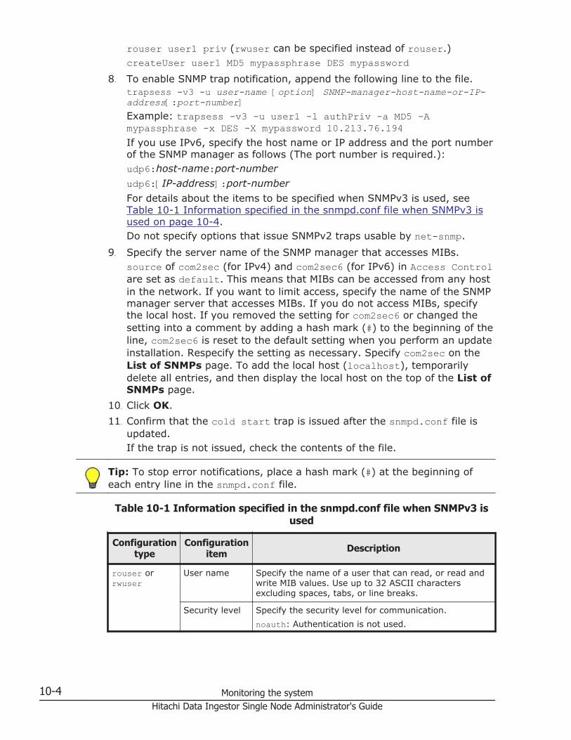
rouser user1 priv (rwuser can be specified instead of rouser.)createUser user1 MD5 mypassphrase DES mypassword
8. To enable SNMP trap notification, append the following line to the file.trapsess -v3 -u user-name [option] SNMP-manager-host-name-or-IP-address[:port-number]Example: trapsess -v3 -u user1 -l authPriv -a MD5 -Amypassphrase -x DES -X mypassword 10.213.76.194If you use IPv6, specify the host name or IP address and the port numberof the SNMP manager as follows (The port number is required.):udp6:host-name:port-number
udp6:[IP-address]:port-number
For details about the items to be specified when SNMPv3 is used, seeTable 10-1 Information specified in the snmpd.conf file when SNMPv3 isused on page 10-4.Do not specify options that issue SNMPv2 traps usable by net-snmp.
9. Specify the server name of the SNMP manager that accesses MIBs.source of com2sec (for IPv4) and com2sec6 (for IPv6) in Access Controlare set as default. This means that MIBs can be accessed from any hostin the network. If you want to limit access, specify the name of the SNMPmanager server that accesses MIBs. If you do not access MIBs, specifythe local host. If you removed the setting for com2sec6 or changed thesetting into a comment by adding a hash mark (#) to the beginning of theline, com2sec6 is reset to the default setting when you perform an updateinstallation. Respecify the setting as necessary. Specify com2sec on theList of SNMPs page. To add the local host (localhost), temporarilydelete all entries, and then display the local host on the top of the List ofSNMPs page.
10. Click OK.
11. Confirm that the cold start trap is issued after the snmpd.conf file isupdated.If the trap is not issued, check the contents of the file.
Tip: To stop error notifications, place a hash mark (#) at the beginning ofeach entry line in the snmpd.conf file.
Table 10-1 Information specified in the snmpd.conf file when SNMPv3 isused
Configurationtype
Configurationitem Description
rouser orrwuser
User name Specify the name of a user that can read, or read andwrite MIB values. Use up to 32 ASCII charactersexcluding spaces, tabs, or line breaks.
Security level Specify the security level for communication.
noauth: Authentication is not used.
10-4 Monitoring the systemHitachi Data Ingestor Single Node Administrator's Guide

Configurationtype
Configurationitem Description
auth: Authentication is used but encryption is notused.
priv: Authentication and encryption are used.
This item can be omitted.
OID When the security level is specified, specify the objectID that can be accessed by the user. This item can beomitted.
createUser User name Specify the user name that is used for SNMPcommunication. Use the user name specified forrouser or rwuser.
Authenticationtype
If you specify auth or priv for the security level forrouser or rwuser, specify the type of userauthentication.
MD5: The HMAC-MD5-96 hash function is used.
SHA: The HMAC-SHA1-96 hash function is used.
Authenticationpassword
If you specify the authentication type, specify theauthentication password by using 8 or more ASCIIcharacters excluding spaces, tabs, or line breaks.
Encryptiontype
If you specify priv for the security level for rouser orrwuser, specify the encryption type for the commonkey.
DES: CBC-DES is used.
AES: CFB-AES-128 is used.
Encryptionpassword
If you specify the encryption type, specify thepassword for encryption by using 8 or more ASCIIcharacters excluding spaces, tabs, or line breaks.
trapsess -v3 -u User name Specify the user name that is used for trap notification.Use the user name specified for rouser or rwuser.
-l Security level If you specify the security level for rouser or rwuser,specify the same security level here. However, thespecified strings are different from the ones specifiedfor rouser or rwuser.
noAuthNoPriv: Authentication is not used.
authNoPriv: Authentication is used but encryption isnot used.
authPriv: Authentication and encryption are used.
-aAuthenticationtype
If you specify the authentication type for createUser,specify the same authentication type (MD5 or SHA).
-AAuthenticationpassword
Specify the authentication password that is specifiedfor createUser.
-x Encryptiontype
If you specify the encryption type for createUser,specify the same encryption type (DES or AES).
Monitoring the system 10-5Hitachi Data Ingestor Single Node Administrator's Guide

Configurationtype
Configurationitem Description
-X Encryptionpassword
Specify the password for encryption that is specifiedfor createUser.
Host name orIP address ofthe SNMPmanager
Specify the host name or IP address of the SNMPmanager to which trap notification is sent.
Port number Specify the port number that is used for trapnotification in the following format:SNMP-manager-host-name-or-IP-address:port-numberThe default is 162. This item can be omitted.
Using error email notificationsThis section explains how to use email for the notification of errorinformation.
GUI used for this operation
• System Information panel on page C-39
• host-name window on page C-44
• System Setup Menu page on page C-93
• Edit System File page on page C-115
To use email notifications
1. In the top-left corner of the GUI, choose the Dashboard tab.
2.
In the System Information panel, click .
3. From the host-name window, click Network & System Configuration inthe Settings area.
4. In the Network & System Configuration dialog box, select systemfrom the Setting Type drop-down list, and then click Display.
5. On the System Setup Menu page (Setting Type: system), click EditSystem File.
6. On the Edit System File page, from the File type drop-down list, selectthe email_alert.conf file, and then click Display.
7. Append the mail server information and the recipient and sender emailaddresses to this file.
8. Click OK.
9. Confirm that the test email is received.A test email is sent with the title HDI Alert (node-host-nameKAQM09112-I).
10-6 Monitoring the systemHitachi Data Ingestor Single Node Administrator's Guide
If you do not receive the test email within five minutes after clicking OKat the specified recipient email address, verify the following and takeaction as appropriate:
¢ The definitions in the email_alert.conf file are valid.
¢ The mail server settings are correct.
¢ The system message KAQM09113-E is not output to the List of RASInformation page (for List of messages) (see List of RASInformation page on page C-32).
Error information emails are sent with the title HDI Alert (node-host-name message-ID).
Note: If you unable to receive error email notifications after enabling them,verify the following and take action as appropriate:
• The system messages KAQM09113-E, KAQM09114-E, KAQM09115-E,KAQM09116-E, and KAQM09117-E are not output to the List of RASInformation page (for List of messages) (see List of RAS Informationpage on page C-32).
• The definitions in the email_alert.conf file are valid.
• The mail server settings have not changed.
Tip: To stop error notifications, place a hash mark (#) at the beginning ofeach entry line in the email_alert.conf file.
Monitoring the system 10-7Hitachi Data Ingestor Single Node Administrator's Guide

10-8 Monitoring the systemHitachi Data Ingestor Single Node Administrator's Guide

11Setting up an environment forcommand and GUI operations
This chapter describes how to set up an environment for command and GUIoperations.
□ Setting up the SSH environment to use commands
□ Setting up a public key certificate
Setting up an environment for command and GUI operations 11-1Hitachi Data Ingestor Single Node Administrator's Guide

Setting up the SSH environment to use commandsThis section explains how to register a public key to use commands.
Prerequisites for registering a public key
SSH2 is supported in HDI systems. Use a key creation tool to create theprivate key and public key that are used in the SSH authentication. Createthe public key in OpenSSH format. For details about how to install therelevant software and create those keys, see the documentation providedwith the software. The passphrase specified when creating the keys is usedas the SSH log on password. You can omit a passphrase.
GUI used for this operation
• System Information panel on page C-39
• host-name window on page C-44
• List of Services page on page C-121
• Local Authentication page on page C-139
• Add Public Key page on page C-158
To register a public key to use commands
1. In the top-left corner of the GUI, choose the Dashboard tab.
2.
In the System Information panel, click .
3. From the host-name window, click Access Protocol Configuration inthe Settings area.
4. On the List of Services page of the Access Protocol Configurationdialog box, select SSH, and then click Modify Configuration.
5. On the Public Key List page, click Add.
6. On the Add Public Key page, specify the public key file, and then clickAdd.The public key is registered for the SSH account nasroot.
For details about how to use commands, see the CLI Administrator'sGuide.
Setting up a public key certificateThis section describes how to set up a public key certificate issued by acertification authority (CA) for a node.
A self-signed certificate has been set up in the node using the default settingbecause communication between a node and GUI is based on SSL. To use apublic key certificate issued by a certificate authority, obtain a certificate froma certificate authority and set the certificate up for a node.
11-2 Setting up an environment for command and GUI operationsHitachi Data Ingestor Single Node Administrator's Guide

Public key certificates and intermediate certificate authority certificates canbe set for a node. Cross certificates cannot be applied.
The execution of commands is required for this operation. See Setting up theSSH environment to use commands on page 11-2 to set up a properenvironment. For details about how to use commands, see the CLIAdministrator's Guide.
To set up a public key certificate issued by a certificate authority fora node
1. Execute the certctl command by using the --create-cert option tocreate a certificate signing request (CSR) and private key.
certctl --create-cert --dest-key private-key-file-name --dest-csr CSR-file-name --key-passwd private-key-password [--country country-name] [--state-province state-or-province-name] [--locality locality-name] [--organization company-or-organization-name] [--unit organization-or-department-unit-name] [--common-name host-name-of-node] [--email E-mail-address] [--challenge-passwd challenge-password] [--optional-company other-company-or-organization-name]
The certificate signing request and private key file will be output to theSSH account home directory (/home/nasroot).
2. Use the scp command or any other method to transfer the CSR file to thelocal disk of the management console or any other appropriate location.
3. Send the certificate signing request to a certificate authority to obtain apublic key certificate.
4. Use the scp command or any other method to transfer the public keycertificate to the HDI.Transfer the file to the home directory for the SSH account (/home/nasroot).
5. Execute the certctl command by using the --create-pkcs option tocreate a keystore in PKCS #12 format.
certctl --create-pkcs --key private-key-file-name --cert public-key-certificate-file-name [--intermediate-cert intermediate-certificate-authority-certificate-file-name] --dest-keystore keystore-file-name --passwd keystore-password --key-passwd private-key-password
The keystore file in PKCS #12 format will be output to the SSH accounthome directory (/home/nasroot).
6. Use the scp command or any other method to transfer the keystore file inPKCS #12 format to the local disk of a machine that has Oracle JDK 6 orlater installed.
7. Import the keystore in PKCS #12 format to a keystore in JKS format.To do this, the machine you are using must have Oracle JDK6 or laterinstalled.Here is an example of creating a keystore file on a Windows machine.
keytool.exe -alias certificate -importkeystore -srckeystore path-of-keystore-in-PKCS-#12-format -destkeystore path-of-keystore-in-JKS-format -
Setting up an environment for command and GUI operations 11-3Hitachi Data Ingestor Single Node Administrator's Guide

srcstoretype pkcs12 -deststoretype jks -destalias alias-name-of-your-choice -destkeypass changeit
If you are prompted to enter the password for the destination keystore,enter the changeit. If you are prompted to enter a password for thesource keystore, enter the password that you specified when you createdthe keystore in PKCS #12 format.
8. Use the scp command or any other method to transfer the keystore file inJKS format to the HDI.Transfer the file to the home directory for the SSH account (/home/nasroot).
9. Execute the certctl command by using the --set-cert option to set upthe following for the node: the certificate obtained from the certificateauthority, the created private key, and the keystore in JKS format.
certctl --set-cert --key private-key-file-name --cert public-key-certificate-file-name [--intermediate-cert intermediate-certificate-authority-certificate-file-name] --keystore keystore-file-name --key-passwd private-key-password [-y]
Tip: To initialize the setting of a public key certificate set up in a node,execute the certctl command by using the --reset option.
11-4 Setting up an environment for command and GUI operationsHitachi Data Ingestor Single Node Administrator's Guide

12Performing an update installation
This chapter describes how to perform an update installation for software.
□ Updating software
Performing an update installation 12-1Hitachi Data Ingestor Single Node Administrator's Guide

Updating softwareThis section explains how to update software running on a node. To updateby using the installation file registered in an HCP system, see Updatingsoftware (using the installation file registered in an HCP system) on page12-2. To update by using the installation media, see Updating software (usingan installation media) on page 12-3.
Note:You cannot use the GUI or a command to execute other operations duringa software update.
Updating software (using the installation file registered in an HCPsystem)
This subsection explains how to use the installation file registered in an HCPsystem to update the software running on a node.
GUI used for this operation
• System Information panel on page C-39
• host-name window on page C-44
• System Software Installation dialog box on page C-75
• Save System Settings Menu page on page C-88
• Save All System Settings page on page C-88
To update the software running on a node by using the installationfile registered in an HCP system:
1. In the top-left corner of the GUI, choose the Dashboard tab.
2.
In the System Information panel, click .
3. From the host-name window, click Software Update in the Settingsarea.
4. If the HCP Anywhere is not linked, click Backup Configuration in theSystem Software Installation dialog box.If the HCP Anywhere is linked, go to step 9.
5. On the Save System Settings Menu page of the BackupConfiguration dialog box, click Save All System Settings.
6. On the Save All System Settings page, click Download.
7. If the information displayed in the confirmation dialog box is correct, clickOK, and then download the system configuration file to a disk outside ofthe system.
8. On the Save All System Settings page, click Close.
9. In the System Software Installation dialog box, select the softwareversion to be installed and the check box, and then click Install.
12-2 Performing an update installationHitachi Data Ingestor Single Node Administrator's Guide
Updating software (using an installation media)This subsection explains how to use an installation media to update thesoftware running on a node.
Before updating the software on a node
• Download all the log files, core files, and dump files before performing theinstallation. After downloading the log files, core files, and dump files,delete the files on the HDI node.
• The node OS must be stopped. To stop the node OS, execute thenasshutdown command before performing the installation.
• Make sure that node services are stopped during installation.
To update the software running on a node by using an installationmedia:
1. Connect the devices (such as the keyboard and monitor) that were usedwhen the system was first set up to the node.
2. Use the power switch on the node to turn on the node.For details about how to use the power switch on the node, see Startingand forcibly stopping a node OS on page H-2.
3. If Press <DEL> to enter setup is displayed in the window, press theDelete key.
4. Select Boot from the Main Menu window.
5. Verify the information displayed in the Boot Menu window.Verify that the items under Boot Option Priorities are displayed in thefollowing order:Boot Option PrioritiesBoot Option #1 [xxxxxxxxxxxxxxxx#]Boot Option #2 [(Bus xx Dev xx)PCI ...]Boot Option #3 [Built-in EFI Shell]If the displayed order is different from the order shown above, change thedisplayed order to the order shown above by selecting the item whoseorder you want to change, and then press the Enter key.#: Information about the external DVD drive is displayed.
6. Insert the installation disc into the node's optical drive.
7. From the Boot Menu window, select Save & Exit.
8. From the Exit Menu window, select Save Changes and Reset if thesettings were changed. From the Exit Menu window, select DiscardChanges and Exit if the settings were not changed.
A confirmation message appears. Select Yes, and then press the Enterkey. If you select Save Changes and Reset, the node restarts.
After then, the installation menu is displayed on the monitor that isconnected to the node.
9. Enter 2 in the installation mode selection window.
Performing an update installation 12-3Hitachi Data Ingestor Single Node Administrator's Guide
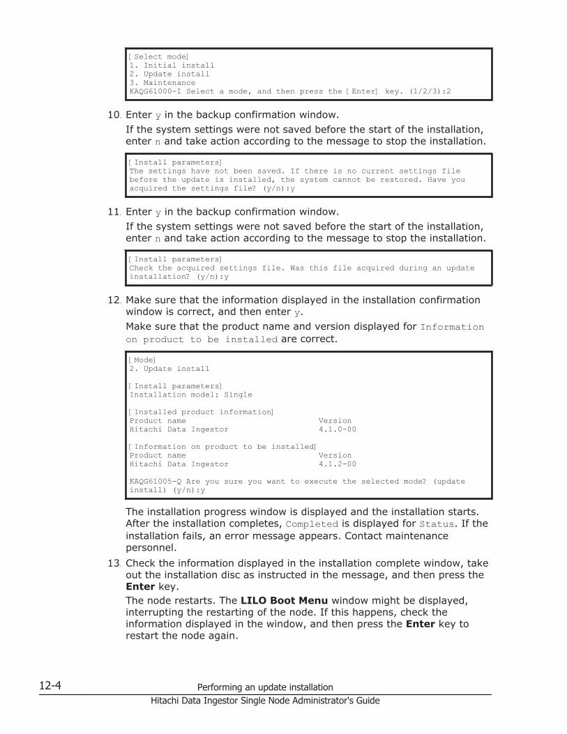
[Select mode]1. Initial install2. Update install3. MaintenanceKAQG61000-I Select a mode, and then press the [Enter] key. (1/2/3):2
10. Enter y in the backup confirmation window.
If the system settings were not saved before the start of the installation,enter n and take action according to the message to stop the installation.
[Install parameters]The settings have not been saved. If there is no current settings file before the update is installed, the system cannot be restored. Have you acquired the settings file? (y/n):y
11. Enter y in the backup confirmation window.
If the system settings were not saved before the start of the installation,enter n and take action according to the message to stop the installation.
[Install parameters]Check the acquired settings file. Was this file acquired during an update installation? (y/n):y
12. Make sure that the information displayed in the installation confirmationwindow is correct, and then enter y.
Make sure that the product name and version displayed for Informationon product to be installed are correct.
[Mode]2. Update install
[Install parameters]Installation model: Single
[Installed product information]Product name VersionHitachi Data Ingestor 4.1.0-00
[Information on product to be installed]Product name VersionHitachi Data Ingestor 4.1.2-00
KAQG61005-Q Are you sure you want to execute the selected mode? (update install) (y/n):y
The installation progress window is displayed and the installation starts.After the installation completes, Completed is displayed for Status. If theinstallation fails, an error message appears. Contact maintenancepersonnel.
13. Check the information displayed in the installation complete window, takeout the installation disc as instructed in the message, and then press theEnter key.The node restarts. The LILO Boot Menu window might be displayed,interrupting the restarting of the node. If this happens, check theinformation displayed in the window, and then press the Enter key torestart the node again.
12-4 Performing an update installationHitachi Data Ingestor Single Node Administrator's Guide
14. Confirm that the login window is displayed on the monitor that isconnected to the node.If the node is restarted and the login window is displayed on the monitor,the installation is complete.
Note: Make sure that the conditions below are satisfied after the installationis completed. If there are problems, see the Single Node TroubleshootingGuide and take the necessary measures.
• There are no problems with the FC paths when a storage system isconnected to the node. (See Hardware window on page C-62 or thedescription of the fpstatus command.)
• There are no problems with the status of the file system. (See FileSystems window on page C-49 or the description of the fslistcommand.)
• The system version is up-to-date. (See host-name window on pageC-44 or the description of the versionlist command.)
• The node is running normally. (See host-name window on page C-44 orthe description of the rgstatus command.)
• There are no problems with the hardware status of the node. (SeeHardware window on page C-62 or the description of the hwstatuscommand.)
If you are using a front bezel, carefully attach the front bezel according to themanual. If you do not know how to attach the front bezel, contactmaintenance personnel.
Performing an update installation 12-5Hitachi Data Ingestor Single Node Administrator's Guide

12-6 Performing an update installationHitachi Data Ingestor Single Node Administrator's Guide
AOperations provided by the GUI
This appendix describes the operation of the GUI.
□ List of operations
Operations provided by the GUI A-1Hitachi Data Ingestor Single Node Administrator's Guide

List of operationsThe following operations can be performed using the GUI.
Table A-1 Operations provided by the GUI
Operation See
ManagingSystemAdministratorAccounts
Changing the password of asystem administrator
Change User Password dialog boxon page C-29
Changing the account securitysettings
Login Security dialog box on pageC-31
Managing aNode
Viewing the status of a node host-name window on page C-44
Changing the settings for a node System Configuration Wizard onpage C-17
Restarting a node Restart Node dialog box on pageC-74
Managing HCPs Setting HCP information Service Configuration Wizard onpage C-19
Setting proxy server information Configure Proxy Server dialog boxon page C-29
Managing FileSystems
Creating a file system Create File System dialog box onpage C-193
Deleting a file system Delete File System dialog box onpage C-210
Changing the settings for a filesystem
Edit File System dialog box onpage C-204
Managing FileShares
Adding a file share Add Share dialog box on pageC-187
Releasing a file share Release Share(s) dialog box onpage C-183
Editing the attributes of a fileshare
Edit Share dialog box on pageC-179
Managing Tasks Managing single-instancing tasksand migration tasks
Task Management dialog box onpage C-4
Managing a task for importing files Import Files window on pageC-71
Importing files Import Files dialog box on pageC-21
Adding a cache resident policy Add Cache Resident Policy dialogbox on page C-212
Editing a cache resident policy Edit Cache Resident Policy dialogbox on page C-213
Deleting a cache resident policy Delete Cache Resident Policydialog box on page C-214
A-2 Operations provided by the GUIHitachi Data Ingestor Single Node Administrator's Guide
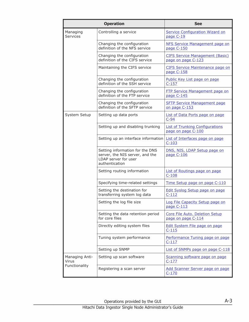
Operation See
ManagingServices
Controlling a service Service Configuration Wizard onpage C-19
Changing the configurationdefinition of the NFS service
NFS Service Management page onpage C-150
Changing the configurationdefinition of the CIFS service
CIFS Service Management (Basic)page on page C-123
Maintaining the CIFS service CIFS Service Maintenance page onpage C-158
Changing the configurationdefinition of the SSH service
Public Key List page on pageC-157
Changing the configurationdefinition of the FTP service
FTP Service Management page onpage C-145
Changing the configurationdefinition of the SFTP service
SFTP Service Management pageon page C-153
System Setup Setting up data ports List of Data Ports page on pageC-94
Setting up and disabling trunking List of Trunking Configurationspage on page C-100
Setting up an interface information List of Interfaces page on pageC-103
Setting information for the DNSserver, the NIS server, and theLDAP server for userauthentication
DNS, NIS, LDAP Setup page onpage C-106
Setting routing information List of Routings page on pageC-108
Specifying time-related settings Time Setup page on page C-110
Setting the destination fortransferring system log data
Edit Syslog Setup page on pageC-112
Setting the log file size Log File Capacity Setup page onpage C-113
Setting the data retention periodfor core files
Core File Auto. Deletion Setuppage on page C-114
Directly editing system files Edit System File page on pageC-115
Tuning system performance Performance Tuning page on pageC-117
Setting up SNMP List of SNMPs page on page C-118
Managing Anti-VirusFunctionality
Setting up scan software Scanning software page on pageC-177
Registering a scan server Add Scanner Server page on pageC-170
Operations provided by the GUI A-3Hitachi Data Ingestor Single Node Administrator's Guide

Operation See
Changing the settings of aregistered scan server
Edit Scanner Server page on pageC-170
Deleting a registered scan server List of Scanner Servers page onpage C-167
Setting scan conditions Scan Conditions page on pageC-171
Enabling or disabling real-timescanning
List of Scanner Servers page onpage C-167
Managing LocalUsers andGroups
Managing local users Local Users dialog box on pageC-75
Managing local groups Local Users dialog box on pageC-75
ViewingHardwareInformation
Viewing hardware information Hardware window on page C-62
ManagingSoftware
Updating software installed on anode
System Software Installationdialog box on page C-75
CollectingSystemConfigurationInformation
Saving system settings Save All System Settings page onpage C-88
Downloading system settings files Save All System Settings page onpage C-88
Uploading system settings files Upload Saved Data page on pageC-92
Setting periodic saving of thesystem settings
Schedule Settings for Saving AllSystem Settings page on pageC-90
Managing NodeErrorInformation
Managing system messages List of RAS Information page (forList of messages) on page C-33
Managing system logs List of RAS Information page (forList of system logs) on pageC-34
Managing other log files List of RAS Information page (forList of other log files) on pageC-35
Downloading or deleting log filesall at one time
List of RAS Information page (forBatch-download) on page C-35
Managing core and dump files List of RAS Information page (forList of core files) on page C-36
Viewing the status of theconnections with external servers
List of RAS Information page (forServer check) on page C-37
Using SNMP to send errorinformation
Edit System File page on pageC-115
Using email to send errorinformation
Edit System File page on pageC-115
A-4 Operations provided by the GUIHitachi Data Ingestor Single Node Administrator's Guide
BBasic GUI operation
This appendix describes basic GUI operations.
□ Window configuration
□ Notes on using the GUI
Basic GUI operation B-1Hitachi Data Ingestor Single Node Administrator's Guide
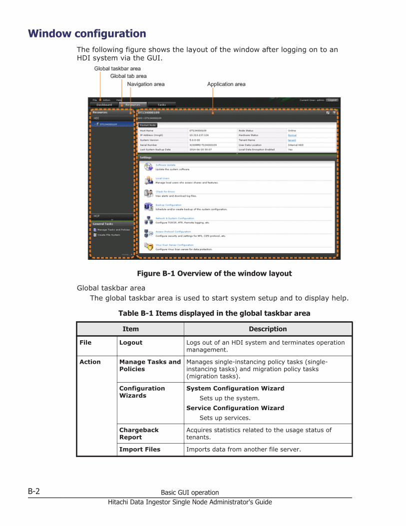
Window configurationThe following figure shows the layout of the window after logging on to anHDI system via the GUI.
Figure B-1 Overview of the window layout
Global taskbar areaThe global taskbar area is used to start system setup and to display help.
Table B-1 Items displayed in the global taskbar area
Item Description
File Logout Logs out of an HDI system and terminates operationmanagement.
Action Manage Tasks andPolicies
Manages single-instancing policy tasks (single-instancing tasks) and migration policy tasks(migration tasks).
ConfigurationWizards
System Configuration Wizard
Sets up the system.
Service Configuration Wizard
Sets up services.
ChargebackReport
Acquires statistics related to the usage status oftenants.
Import Files Imports data from another file server.
B-2 Basic GUI operationHitachi Data Ingestor Single Node Administrator's Guide
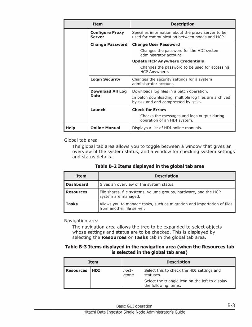
Item Description
Configure ProxyServer
Specifies information about the proxy server to beused for communication between nodes and HCP.
Change Password Change User Password
Changes the password for the HDI systemadministrator account.
Update HCP Anywhere Credentials
Changes the password to be used for accessingHCP Anywhere.
Login Security Changes the security settings for a systemadministrator account.
Download All LogData
Downloads log files in a batch operation.
In batch downloading, multiple log files are archivedby tar and and compressed by gzip.
Launch Check for Errors
Checks the messages and logs output duringoperation of an HDI system.
Help Online Manual Displays a list of HDI online manuals.
Global tab areaThe global tab area allows you to toggle between a window that gives anoverview of the system status, and a window for checking system settingsand status details.
Table B-2 Items displayed in the global tab area
Item Description
Dashboard Gives an overview of the system status.
Resources File shares, file systems, volume groups, hardware, and the HCPsystem are managed.
Tasks Allows you to manage tasks, such as migration and importation of filesfrom another file server.
Navigation areaThe navigation area allows the tree to be expanded to select objectswhose settings and status are to be checked. This is displayed byselecting the Resources or Tasks tab in the global tab area.
Table B-3 Items displayed in the navigation area (when the Resources tabis selected in the global tab area)
Item Description
Resources HDI host-name
Select this to check the HDI settings andstatuses.
Select the triangle icon on the left to displaythe following items:
Basic GUI operation B-3Hitachi Data Ingestor Single Node Administrator's Guide
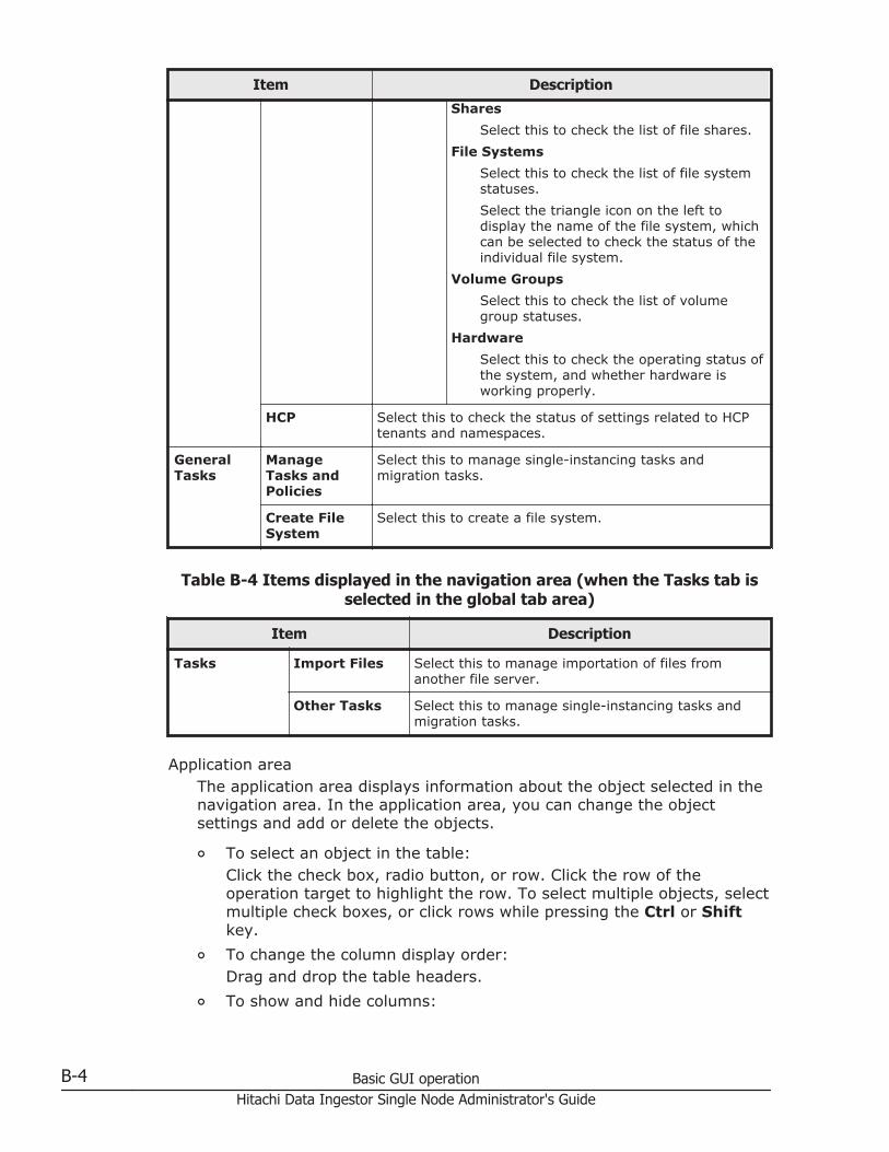
Item Description
Shares
Select this to check the list of file shares.
File Systems
Select this to check the list of file systemstatuses.
Select the triangle icon on the left todisplay the name of the file system, whichcan be selected to check the status of theindividual file system.
Volume Groups
Select this to check the list of volumegroup statuses.
Hardware
Select this to check the operating status ofthe system, and whether hardware isworking properly.
HCP Select this to check the status of settings related to HCPtenants and namespaces.
GeneralTasks
ManageTasks andPolicies
Select this to manage single-instancing tasks andmigration tasks.
Create FileSystem
Select this to create a file system.
Table B-4 Items displayed in the navigation area (when the Tasks tab isselected in the global tab area)
Item Description
Tasks Import Files Select this to manage importation of files fromanother file server.
Other Tasks Select this to manage single-instancing tasks andmigration tasks.
Application areaThe application area displays information about the object selected in thenavigation area. In the application area, you can change the objectsettings and add or delete the objects.
¢ To select an object in the table:Click the check box, radio button, or row. Click the row of theoperation target to highlight the row. To select multiple objects, selectmultiple check boxes, or click rows while pressing the Ctrl or Shiftkey.
¢ To change the column display order:Drag and drop the table headers.
¢ To show and hide columns:
B-4 Basic GUI operationHitachi Data Ingestor Single Node Administrator's Guide
Click the Column Settings button to specify the names of thecolumns to be displayed. From the dialog box that is displayed whenthe Column Settings button is clicked, you can see item descriptionsas well as drag and drop rows to change the display order.
¢ To sort the displayed items:Click the table header to toggle between ascending and descendingorder.
¢ To filter displayed items:Click the Filter button, and then specify conditions. Select either Onor Off for the filtering option to hide or show the filtered displayitems.
¢ To display information page by page:From the Rows/page drop-down list, select the number of lines to bedisplayed per page. In the Page text box, the page number of thecurrently displayed page and the total number of pages are displayed.You can move to the specified page by entering the page number inthe text box and pressing the Enter key. You can also click buttons todisplay the first page, the previous page, the next page, or the finalpage.
¢ To update displayed information:
Click (update).
¢ To get help:
Click (help).
¢ To maximize or minimize a dialog box:
Click (maximize) or (minimize).
Notes on using the GUINote the following when using the GUI:
• Do not open multiple windows to perform operations simultaneously.
• Some time might be required to display recently updated information inthe GUI.
• If a window is closed while a page is loading, an error sometimes occursthe next time a window is opened, and no operations can be performed. Ifthis happens, close all open Web browsers, and then start over from thebeginning.
• If you perform an operation in a dialog box while the network load is high,some information might not be displayed in the dialog box. If thishappens, close and re-open the dialog box, confirm the status, and thenperform the intended operation.
Basic GUI operation B-5Hitachi Data Ingestor Single Node Administrator's Guide

B-6 Basic GUI operationHitachi Data Ingestor Single Node Administrator's Guide
CGUI reference
This appendix describes items displayed in the GUI and how to use eachwindow.
□ Task Management dialog box
□ System Configuration Wizard
□ Service Configuration Wizard
□ Download Chargeback Report dialog box
□ Import Files dialog box
□ Configure Proxy Server dialog box
□ Change User Password dialog box
□ Update HCP Anywhere Credentials dialog box
□ Login Security dialog box
□ Check for Errors dialog box
□ Dashboard tab
□ host-name window
□ Shares window
□ File Systems window
GUI reference C-1Hitachi Data Ingestor Single Node Administrator's Guide
□ file-system-name window
□ Volume Groups window
□ Hardware window
□ tenant-name window
□ Import Files window
□ Restart Node dialog box
□ System Software Installation dialog box
□ Local Users dialog box
□ Backup Configuration dialog box
□ Network & System Configuration dialog box
□ Access Protocol Configuration dialog box
□ Virus Scan Server Configuration dialog box
□ CIFS Protocol Settings dialog box
□ NFS Protocol Settings dialog box
□ Edit Share dialog box
□ Release Share(s) dialog box
□ Edit CIFS Share Host or Network dialog box
□ Add CIFS Share Host or Network dialog box
□ Edit NFS Share Host or Network dialog box
□ Add NFS Share Host or Network dialog box
□ Add Share dialog box
□ Create File System dialog box
C-2 GUI referenceHitachi Data Ingestor Single Node Administrator's Guide
□ Edit File System dialog box
□ Delete File System dialog box
□ Advanced ACL Settings dialog box
□ Add Cache Resident Policy dialog box
□ Edit Cache Resident Policy dialog box
□ Delete Cache Resident Policy dialog box
□ Provisioning Wizard
GUI reference C-3Hitachi Data Ingestor Single Node Administrator's Guide
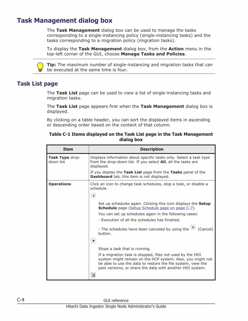
Task Management dialog boxThe Task Management dialog box can be used to manage the taskscorresponding to a single-instancing policy (single-instancing tasks) and thetasks corresponding to a migration policy (migration tasks).
To display the Task Management dialog box, from the Action menu in thetop-left corner of the GUI, choose Manage Tasks and Policies.
Tip: The maximum number of single-instancing and migration tasks that canbe executed at the same time is four.
Task List pageThe Task List page can be used to view a list of single-instancing tasks andmigration tasks.
The Task List page appears first when the Task Management dialog box isdisplayed.
By clicking on a table header, you can sort the displayed items in ascendingor descending order based on the content of that column.
Table C-1 Items displayed on the Task List page in the Task Managementdialog box
Item Description
Task Type drop-down list
Displays information about specific tasks only. Select a task typefrom the drop-down list. If you select All, all the tasks aredisplayed.
If you display the Task List page from the Tasks panel of theDashboard tab, this item is not displayed.
Operations Click an icon to change task schedules, stop a task, or disable aschedule.
Set up schedules again. Clicking this icon displays the SetupSchedule page (Setup Schedule page on page C-7).
You can set up schedules again in the following cases:
- Execution of all the schedules has finished.
- The schedules have been canceled by using the (Cancel)button.
Stops a task that is running.
If a migration task is stopped, files not used by the HDIsystem might remain on the HCP system. Also, you might notbe able to use the data to restore the file system, view thepast versions, or share the data with another HDI system.
C-4 GUI referenceHitachi Data Ingestor Single Node Administrator's Guide
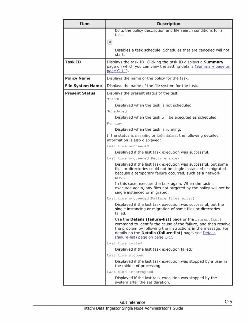
Item Description
Edits the policy description and file search conditions for atask.
Disables a task schedule. Schedules that are canceled will notstart.
Task ID Displays the task ID. Clicking the task ID displays a Summarypage on which you can view the setting details (Summary page onpage C-11).
Policy Name Displays the name of the policy for the task.
File System Name Displays the name of the file system for the task.
Present Status Displays the present status of the task.
StandbyDisplayed when the task is not scheduled.
ScheduledDisplayed when the task will be executed as scheduled.
RunningDisplayed when the task is running.
If the status is Standby or Scheduled, the following detailedinformation is also displayed:
Last time succeededDisplayed if the last task execution was successful.
Last time succeeded(Retry enable)Displayed if the last task execution was successful, but somefiles or directories could not be single instanced or migratedbecause a temporary failure occurred, such as a networkerror.
In this case, execute the task again. When the task isexecuted again, any files not targeted by the policy will not besingle instanced or migrated.
Last time succeeded(Failure files exist)Displayed if the last task execution was successful, but thesingle instancing or migration of some files or directoriesfailed.
Use the Details (failure-list) page or the arcresultctlcommand to identify the cause of the failure, and then resolvethe problem by following the instructions in the message. Fordetails on the Details (failure-list) page, see Details(failure-list) page on page C-15.
Last time failedDisplayed if the last task execution failed.
Last time stoppedDisplayed if the last task execution was stopped by a user inthe middle of processing.
Last time interruptedDisplayed if the last task execution was stopped by thesystem after the set duration.
GUI reference C-5Hitachi Data Ingestor Single Node Administrator's Guide
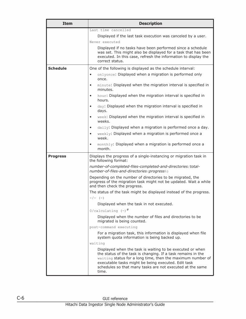
Item DescriptionLast time cancelled
Displayed if the last task execution was canceled by a user.
Never executedDisplayed if no tasks have been performed since a schedulewas set. This might also be displayed for a task that has beenexecuted. In this case, refresh the information to display thecorrect status.
Schedule One of the following is displayed as the schedule interval:
• onlyonce: Displayed when a migration is performed onlyonce.
• minute: Displayed when the migration interval is specified inminutes.
• hour: Displayed when the migration interval is specified inhours.
• day: Displayed when the migration interval is specified indays.
• week: Displayed when the migration interval is specified inweeks.
• daily: Displayed when a migration is performed once a day.
• weekly: Displayed when a migration is performed once aweek.
• monthly: Displayed when a migration is performed once amonth.
Progress Displays the progress of a single-instancing or migration task inthe following format:
number-of-completed-files-completed-and-directories/total-number-of-files-and-directories(progress%)Depending on the number of directories to be migrated, theprogress of the migration task might not be updated. Wait a whileand then check the progress.
The status of the task might be displayed instead of the progress.
-/- (-)Displayed when the task in not executed.
0/calculating (-)#
Displayed when the number of files and directories to bemigrated is being counted.
post-command executingFor a migration task, this information is displayed when filesystem quota information is being backed up.
waitingDisplayed when the task is waiting to be executed or whenthe status of the task is changing. If a task remains in thewaiting status for a long time, then the maximum number ofexecutable tasks might be being executed. Edit taskschedules so that many tasks are not executed at the sametime.
C-6 GUI referenceHitachi Data Ingestor Single Node Administrator's Guide

Item Description
Refresh button Click this button to refresh the displayed information.
#: If you perform a task for a file system that contains a million or more files anddirectories, the status might not change from the state in which files and directories arebeing counted. If this happens, do the following:
1. Stop the task being performed.
2. Use the arcmodectl command to enable initial mode every time the task is executed.
3. Verify that initial mode is enabled, and then perform the task.
If the number of files and directories falls below 1,000,000, use the arcmodectlcommand to disable initial mode.
Setup Schedule pageYou can set up task schedules.
Note: You can change only the settings of the tasks for which execution of allthe schedules has been completed or whose schedules have been disabled. Ifa schedule is running, wait until it finishes, or on the Task List page, click
. To disable a schedule, on the Task List page, click .
To display the Setup Schedule page, click on the Task List page.
Table C-2 Items displayed on the Setup Schedule page in the TaskManagement dialog box
Item Description
Policy Name Displays the policy name corresponding to the selected task.
Initial ScheduledDate and Time
Set a date and time for executing the initial task depending on theserver time zone.
To execute immediately, select the Run immediately. check box.
Date To execute on a specific date and time, specifythe date in YYYY-MM-DD format, or select adate by using the calendar icon to the right.
Time To execute on a specific date and time, specifythe time in HH:MM format.
Repetitive TaskScheduling
Specify the interval and the number of single-instancing ormigration tasks to perform.
Interval unit Select an interval from the drop-down list.
• Only Once: Executed only once
• Minute (fixed interval): For specifying aninterval in minutes
• Hour (fixed interval): For specifying aninterval in hours
• Day (fixed interval): For specifying aninterval in days
GUI reference C-7Hitachi Data Ingestor Single Node Administrator's Guide

Item Description
• Week (fixed interval): For specifying aninterval in weeks
• Daily (fixed time): Every day
• Weekly (fixed time): Every week
• Monthly (fixed time): Every month
Interval If Minute (fixed interval), Hour (fixedinterval), Day (fixed interval), or Week(fixed interval) is selected for Interval unit,specify a number for that unit within thefollowing range:
• Minute (fixed interval) or Hour (fixedinterval): 1 to 1000
• Day (fixed interval): 1 to 500• Week (fixed interval): 1 to 50For example, to execute a task every five hours,select Hour (fixed interval) for Interval unit,and then specify 5 for Interval.
Stop after firstnumberoccurrences
Specify the number of tasks to execute, in therange from 0 to 99. If you do not want to limitthe number of migrations, omit this item orspecify 0. If you select Only Once for Intervalunit, you do not need to specify this item.
Maximumduration
Specify the time from when a task is started towhen it will be stopped (the maximumexecution time), in the range from 0 to 999hours. To apply no time limit, either omit thissetting or specify 0.
Edit Policy page
To display the Edit Policy page, on the Task List page, click for thetarget task. The 1. Policy Name page first appears.
Table C-3 Pages displayed on the Edit Policy page
Page Description
1. Policy Name Specify the policy description as necessary, and then click Next.
• Policy Name: Displays the name of the policy correspondingto the task.
• Policy Description: Enter a policy description in 256 orfewer characters. You cannot use forward slashes (/), doublequotation marks ("), or line feed characters. This item can beomitted.
2. Criteria Specify the required information, and then click Confirm.
• Condition: Specifies conditions for a file to be searched for.
C-8 GUI referenceHitachi Data Ingestor Single Node Administrator's Guide

Page Description
Match All: Searches for a file that satisfies all of theconditions.
Match Any: Searches for a file that satisfies a condition.
• Each condition to be defined: Use the drop-down list or textbox to specify the conditions for selecting a file to be searchesfor.
This condition consists of the type, comparison operator, andoperand from the left. For details about the values that can bespecified for each item, see Table C-4 Conditions that can bespecified for the Condition in the Edit Policy page on pageC-9.
Note that you can use the + button to the right of eachcondition to add a new condition. You can use the - button todelete a condition. A maximum of 100 conditions can becreated.
Table C-4 Conditions that can be specified for the Condition in the EditPolicy page
Type Comparison operator Operand
File Is All (all files)
File Extension Is
Is not
Specify the file extension in 400characters or less. Use a comma (,) toseparate multiple file extensions.Upper-case and lower-case letters aredistinguished.
File Name Is
Is not
When editing the migration policy,specify a file name by using no morethan 1,023 characters. Upper-caseand lower-case letters aredistinguished.
You can specify asterisks (*) orquestion marks (?) as wildcards. Anasterisk can correspond to zero ormore characters, and a question markcorresponds to exactly one character.
For multi-byte characters, onlyUnicode (UTF-8) characters aretargeted for search.
Directory Path Starts with
Does not start with
When editing the migration policy,specify a directory path by using nomore than 4,095 characters. Upper-case and lower-case letters aredistinguished. All files under thespecified directory are targeted forsearch (or not targeted for search inthe case of Does not start with).
For example, specify example/tmpwhen targeting files under /mnt/fs01/example/tmp/.
GUI reference C-9Hitachi Data Ingestor Single Node Administrator's Guide
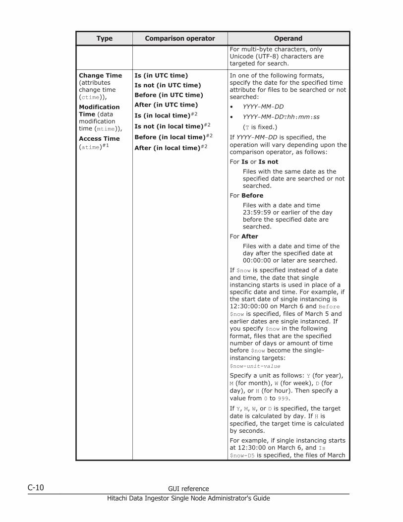
Type Comparison operator Operand
For multi-byte characters, onlyUnicode (UTF-8) characters aretargeted for search.
Change Time(attributeschange time(ctime)),
ModificationTime (datamodificationtime (mtime)),
Access Time(atime)#1
Is (in UTC time)
Is not (in UTC time)
Before (in UTC time)
After (in UTC time)
Is (in local time)#2
Is not (in local time)#2
Before (in local time)#2
After (in local time)#2
In one of the following formats,specify the date for the specified timeattribute for files to be searched or notsearched:
• YYYY-MM-DD
• YYYY-MM-DDThh:mm:ss
(T is fixed.)
If YYYY-MM-DD is specified, theoperation will vary depending upon thecomparison operator, as follows:
For Is or Is not
Files with the same date as thespecified date are searched or notsearched.
For Before
Files with a date and time23:59:59 or earlier of the daybefore the specified date aresearched.
For After
Files with a date and time of theday after the specified date at00:00:00 or later are searched.
If $now is specified instead of a dateand time, the date that singleinstancing starts is used in place of aspecific date and time. For example, ifthe start date of single instancing is12:30:00:00 on March 6 and Before$now is specified, files of March 5 andearlier dates are single instanced. Ifyou specify $now in the followingformat, files that are the specifiednumber of days or amount of timebefore $now become the single-instancing targets:$now-unit-valueSpecify a unit as follows: Y (for year),M (for month), W (for week), D (forday), or H (for hour). Then specify avalue from 0 to 999.
If Y, M, W, or D is specified, the targetdate is calculated by day. If H isspecified, the target time is calculatedby seconds.
For example, if single instancing startsat 12:30:00 on March 6, and Is$now-D5 is specified, the files of March
C-10 GUI referenceHitachi Data Ingestor Single Node Administrator's Guide
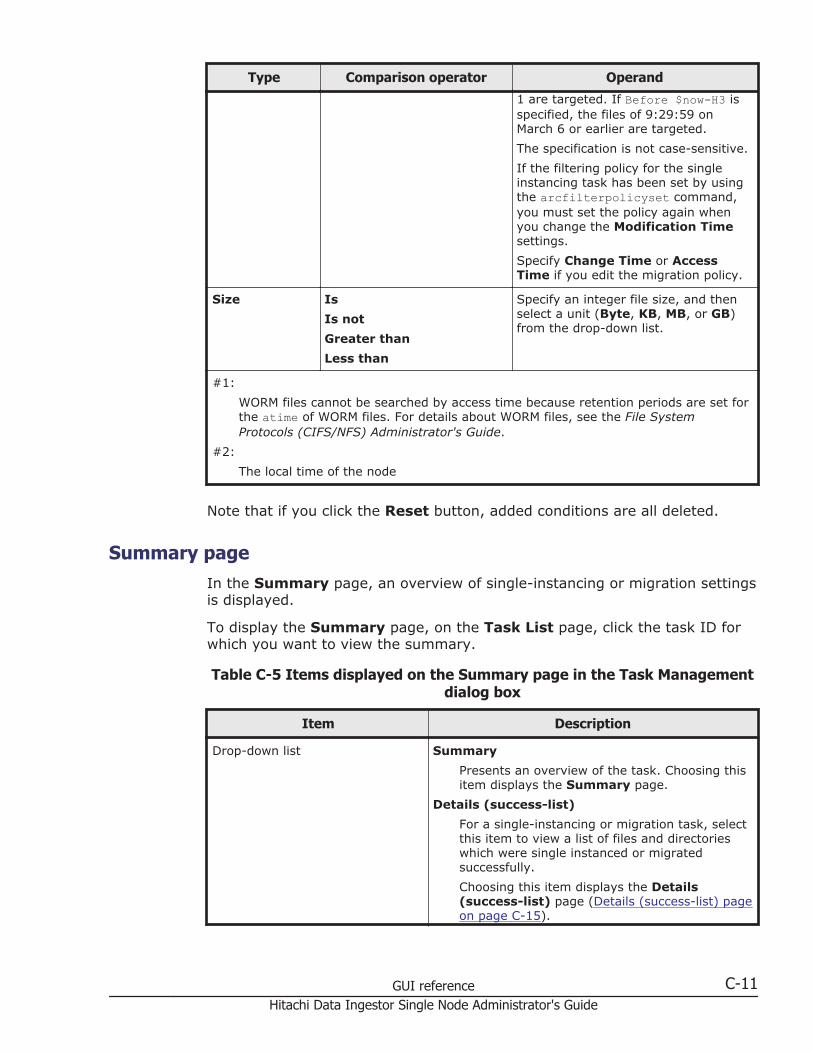
Type Comparison operator Operand
1 are targeted. If Before $now-H3 isspecified, the files of 9:29:59 onMarch 6 or earlier are targeted.
The specification is not case-sensitive.
If the filtering policy for the singleinstancing task has been set by usingthe arcfilterpolicyset command,you must set the policy again whenyou change the Modification Timesettings.
Specify Change Time or AccessTime if you edit the migration policy.
Size Is
Is not
Greater than
Less than
Specify an integer file size, and thenselect a unit (Byte, KB, MB, or GB)from the drop-down list.
#1:
WORM files cannot be searched by access time because retention periods are set forthe atime of WORM files. For details about WORM files, see the File SystemProtocols (CIFS/NFS) Administrator's Guide.
#2:
The local time of the node
Note that if you click the Reset button, added conditions are all deleted.
Summary pageIn the Summary page, an overview of single-instancing or migration settingsis displayed.
To display the Summary page, on the Task List page, click the task ID forwhich you want to view the summary.
Table C-5 Items displayed on the Summary page in the Task Managementdialog box
Item Description
Drop-down list Summary
Presents an overview of the task. Choosing thisitem displays the Summary page.
Details (success-list)
For a single-instancing or migration task, selectthis item to view a list of files and directorieswhich were single instanced or migratedsuccessfully.
Choosing this item displays the Details(success-list) page (Details (success-list) pageon page C-15).
GUI reference C-11Hitachi Data Ingestor Single Node Administrator's Guide
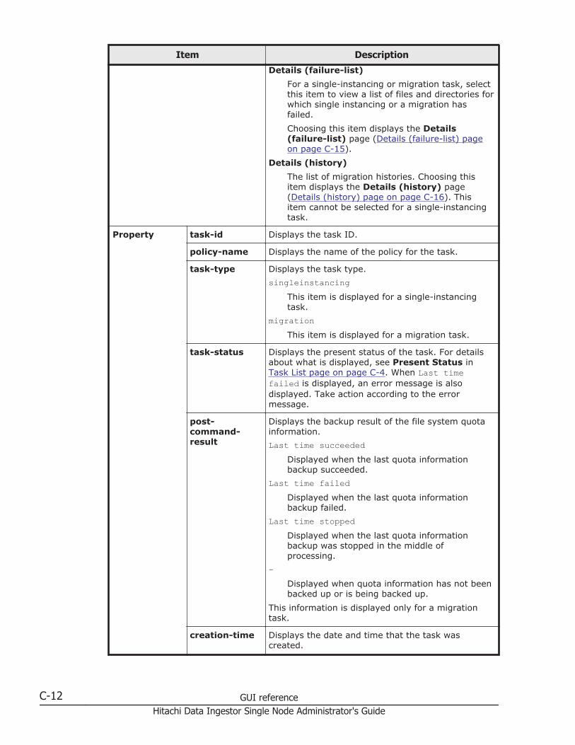
Item Description
Details (failure-list)
For a single-instancing or migration task, selectthis item to view a list of files and directories forwhich single instancing or a migration hasfailed.
Choosing this item displays the Details(failure-list) page (Details (failure-list) pageon page C-15).
Details (history)
The list of migration histories. Choosing thisitem displays the Details (history) page(Details (history) page on page C-16). Thisitem cannot be selected for a single-instancingtask.
Property task-id Displays the task ID.
policy-name Displays the name of the policy for the task.
task-type Displays the task type.
singleinstancingThis item is displayed for a single-instancingtask.
migrationThis item is displayed for a migration task.
task-status Displays the present status of the task. For detailsabout what is displayed, see Present Status inTask List page on page C-4. When Last timefailed is displayed, an error message is alsodisplayed. Take action according to the errormessage.
post-command-result
Displays the backup result of the file system quotainformation.
Last time succeededDisplayed when the last quota informationbackup succeeded.
Last time failedDisplayed when the last quota informationbackup failed.
Last time stoppedDisplayed when the last quota informationbackup was stopped in the middle ofprocessing.
-Displayed when quota information has not beenbacked up or is being backed up.
This information is displayed only for a migrationtask.
creation-time Displays the date and time that the task wascreated.
C-12 GUI referenceHitachi Data Ingestor Single Node Administrator's Guide
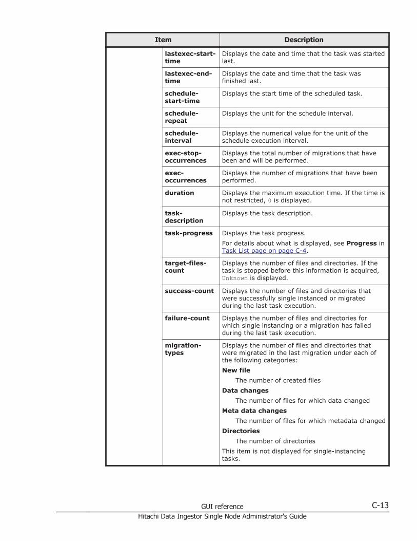
Item Description
lastexec-start-time
Displays the date and time that the task was startedlast.
lastexec-end-time
Displays the date and time that the task wasfinished last.
schedule-start-time
Displays the start time of the scheduled task.
schedule-repeat
Displays the unit for the schedule interval.
schedule-interval
Displays the numerical value for the unit of theschedule execution interval.
exec-stop-occurrences
Displays the total number of migrations that havebeen and will be performed.
exec-occurrences
Displays the number of migrations that have beenperformed.
duration Displays the maximum execution time. If the time isnot restricted, 0 is displayed.
task-description
Displays the task description.
task-progress Displays the task progress.
For details about what is displayed, see Progress inTask List page on page C-4.
target-files-count
Displays the number of files and directories. If thetask is stopped before this information is acquired,Unknown is displayed.
success-count Displays the number of files and directories thatwere successfully single instanced or migratedduring the last task execution.
failure-count Displays the number of files and directories forwhich single instancing or a migration has failedduring the last task execution.
migration-types
Displays the number of files and directories thatwere migrated in the last migration under each ofthe following categories:
New file
The number of created files
Data changes
The number of files for which data changed
Meta data changes
The number of files for which metadata changed
Directories
The number of directories
This item is not displayed for single-instancingtasks.
GUI reference C-13Hitachi Data Ingestor Single Node Administrator's Guide
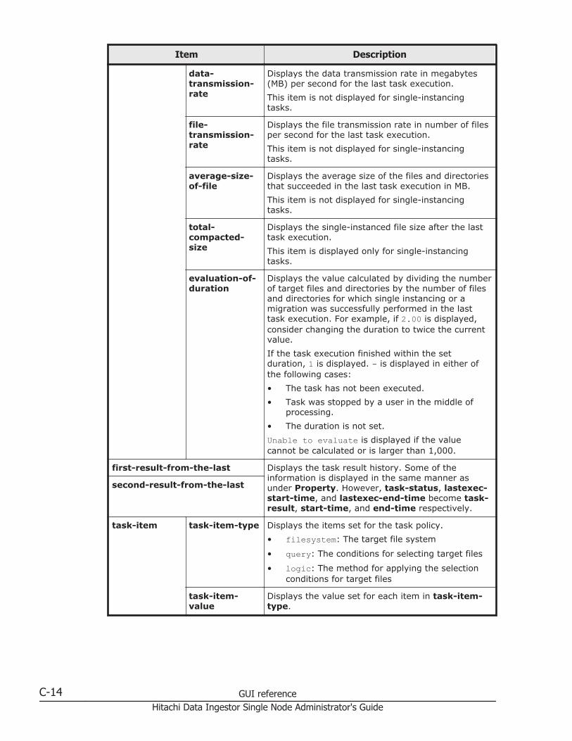
Item Description
data-transmission-rate
Displays the data transmission rate in megabytes(MB) per second for the last task execution.
This item is not displayed for single-instancingtasks.
file-transmission-rate
Displays the file transmission rate in number of filesper second for the last task execution.
This item is not displayed for single-instancingtasks.
average-size-of-file
Displays the average size of the files and directoriesthat succeeded in the last task execution in MB.
This item is not displayed for single-instancingtasks.
total-compacted-size
Displays the single-instanced file size after the lasttask execution.
This item is displayed only for single-instancingtasks.
evaluation-of-duration
Displays the value calculated by dividing the numberof target files and directories by the number of filesand directories for which single instancing or amigration was successfully performed in the lasttask execution. For example, if 2.00 is displayed,consider changing the duration to twice the currentvalue.
If the task execution finished within the setduration, 1 is displayed. - is displayed in either ofthe following cases:
• The task has not been executed.
• Task was stopped by a user in the middle ofprocessing.
• The duration is not set.
Unable to evaluate is displayed if the valuecannot be calculated or is larger than 1,000.
first-result-from-the-last Displays the task result history. Some of theinformation is displayed in the same manner asunder Property. However, task-status, lastexec-start-time, and lastexec-end-time become task-result, start-time, and end-time respectively.
second-result-from-the-last
task-item task-item-type Displays the items set for the task policy.
• filesystem: The target file system
• query: The conditions for selecting target files
• logic: The method for applying the selectionconditions for target files
task-item-value
Displays the value set for each item in task-item-type.
C-14 GUI referenceHitachi Data Ingestor Single Node Administrator's Guide

Details (success-list) pageThe Details (success-list) page displays a list of files and directories (atotal of up to one million successful or failed files and directories) that weresingle instanced or migrated successfully.
Note:
• If you stop a task that is being executed, only the files and directories forwhich single instancing or a migration has completed at the time that thetask is stopped are displayed.
• If you enter a string in the Filter text box, only the paths that containthat string are displayed in value-list, and the number of paths thatcontain the string is displayed in total-count. Use only Unicode (UTF-8)when specifying multi-byte characters for a filter.
• You can download a UTF-8-format text file that contains the list ofselected files by specifying Offset and Max-count in Download value-list and then clicking Download. If the value-list is filtered, unfilter itbefore downloading a file.
• The file paths that contain multi-byte characters other than Unicode(UTF-8) characters are not correctly displayed.
To display the Details (success-list) page, choose Details (success-list)from the drop-down list on the Summary page.
Table C-6 Items displayed on the Details (success-list) page in the TaskManagement dialog box
Item Description
Filter If you specify a character string, only the paths that containthat character string are displayed in value-list. The totalnumber of paths that contain the character string is displayedin total-count.
Property view-count
Displays the number of files and directories displayed invalue-list on the current page.
offset-range
Displays the offset range from the top of the list, for files anddirectories displayed in value-list on the current page. Forexample, if the first 10 items are displayed on the currentpage, 0-9 is displayed.
none is displayed if there are no files and directories to display.
total-count
Displays the total number of target files and directories.
value-list Displays the paths to target files and directories.
Details (failure-list) pageThe Details (failure-list) page displays a list of files and directories (a totalof up to one million successful or failed files and directories) for which singleinstancing or a migration failed.
GUI reference C-15Hitachi Data Ingestor Single Node Administrator's Guide
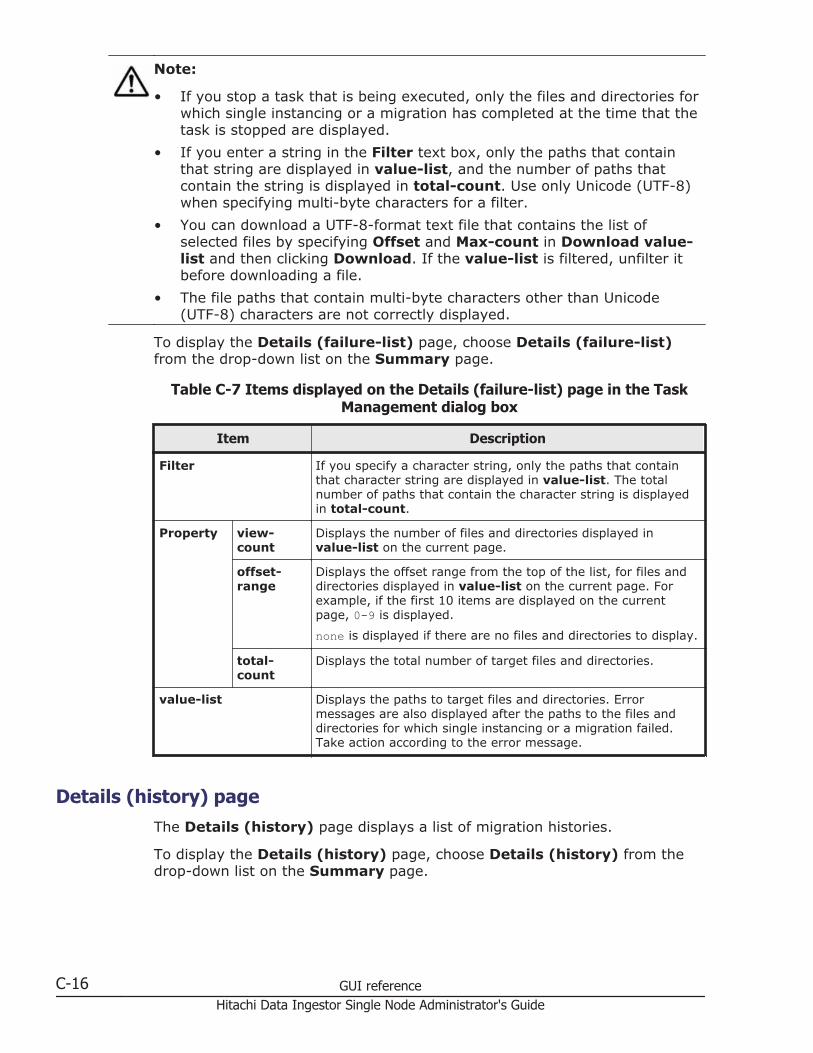
Note:
• If you stop a task that is being executed, only the files and directories forwhich single instancing or a migration has completed at the time that thetask is stopped are displayed.
• If you enter a string in the Filter text box, only the paths that containthat string are displayed in value-list, and the number of paths thatcontain the string is displayed in total-count. Use only Unicode (UTF-8)when specifying multi-byte characters for a filter.
• You can download a UTF-8-format text file that contains the list ofselected files by specifying Offset and Max-count in Download value-list and then clicking Download. If the value-list is filtered, unfilter itbefore downloading a file.
• The file paths that contain multi-byte characters other than Unicode(UTF-8) characters are not correctly displayed.
To display the Details (failure-list) page, choose Details (failure-list)from the drop-down list on the Summary page.
Table C-7 Items displayed on the Details (failure-list) page in the TaskManagement dialog box
Item Description
Filter If you specify a character string, only the paths that containthat character string are displayed in value-list. The totalnumber of paths that contain the character string is displayedin total-count.
Property view-count
Displays the number of files and directories displayed invalue-list on the current page.
offset-range
Displays the offset range from the top of the list, for files anddirectories displayed in value-list on the current page. Forexample, if the first 10 items are displayed on the currentpage, 0-9 is displayed.
none is displayed if there are no files and directories to display.
total-count
Displays the total number of target files and directories.
value-list Displays the paths to target files and directories. Errormessages are also displayed after the paths to the files anddirectories for which single instancing or a migration failed.Take action according to the error message.
Details (history) pageThe Details (history) page displays a list of migration histories.
To display the Details (history) page, choose Details (history) from thedrop-down list on the Summary page.
C-16 GUI referenceHitachi Data Ingestor Single Node Administrator's Guide
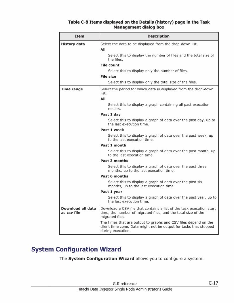
Table C-8 Items displayed on the Details (history) page in the TaskManagement dialog box
Item Description
History data Select the data to be displayed from the drop-down list.
All
Select this to display the number of files and the total size ofthe files.
File count
Select this to display only the number of files.
File size
Select this to display only the total size of the files.
Time range Select the period for which data is displayed from the drop-downlist.
All
Select this to display a graph containing all past executionresults.
Past 1 day
Select this to display a graph of data over the past day, up tothe last execution time.
Past 1 week
Select this to display a graph of data over the past week, upto the last execution time.
Past 1 month
Select this to display a graph of data over the past month, upto the last execution time.
Past 3 months
Select this to display a graph of data over the past threemonths, up to the last execution time.
Past 6 months
Select this to display a graph of data over the past sixmonths, up to the last execution time.
Past 1 year
Select this to display a graph of data over the past year, up tothe last execution time.
Download all dataas csv file
Download a CSV file that contains a list of the task execution starttime, the number of migrated files, and the total size of themigrated files.
The times that are output to graphs and CSV files depend on theclient time zone. Data might not be output for tasks that stoppedduring execution.
System Configuration WizardThe System Configuration Wizard allows you to configure a system.
GUI reference C-17Hitachi Data Ingestor Single Node Administrator's Guide

To display the System Configuration Wizard, click the Action menu in thetop-left corner of the GUI, and then choose Configuration Wizards-SystemConfiguration Wizard.
Table C-9 Pages displayed in the System Configuration Wizard
Pages Description
1. Introduction Check the contents displayed on the page, and then click Next.
2. License Settings Set the license for using the HDI software, and then click Next.
There are two ways to set the license key: specifying a license keyfile, and directly entering a license key string into the dialog box.
Note that this page does not appear if the System ConfigurationWizard is displayed by using the Provisioning Wizard.
3. Basic Settings Specify the following information, and then click Next.
• Registering node network information: host name#, systemmanagement IP address, netmask or prefix length, IP addressof the default gateway (optional)
When Use DHCP is selected, you can use DHCP to assign thesystem management IP address, netmask, and IP address ofthe default gateway.
• Registering the DNS server: IP address of the primary server(optional when Use DHCP is selected), IP address of thesecondary server (optional), default domain name (optional)
• Setting the time on the node: Specify a time zone and theneither specify the NTP server name, or specify the timemanually.
• Encryption setting: Specify whether to encrypt internal harddisks that contain user data. You can specify this setting if anencryption license is set.
If you are using DHCP and the DNS server is already registered tothe DHCP server, the information obtained from the DHCP serveris set as the DNS server information. In this case, manuallyspecified information is ignored.
If the common key used for encryption is corrupted or cannot beobtained, user data will no longer be available. We recommendthat you use the encdisplaykey command to display the key, andsave the key on external media.
4. Confirmation Check the information displayed on the page, select the checkbox, and then click Apply.
5. Execution Displays the execution status of system configuration.
6. Completion Make sure that the processing results are correct, and then clickFinish.
#: Specify a host name that has 15 or fewer characters. You can use alphanumericcharacters and hyphens (-). The host name must begin with an alphabetic character,and must not end with a hyphen (-). System-reserved words cannot be specifiedregardless of the case of letters. For system-reserved words, see List of reserved wordson page E-2. In the initial settings, a unique name is assigned to each node.
C-18 GUI referenceHitachi Data Ingestor Single Node Administrator's Guide
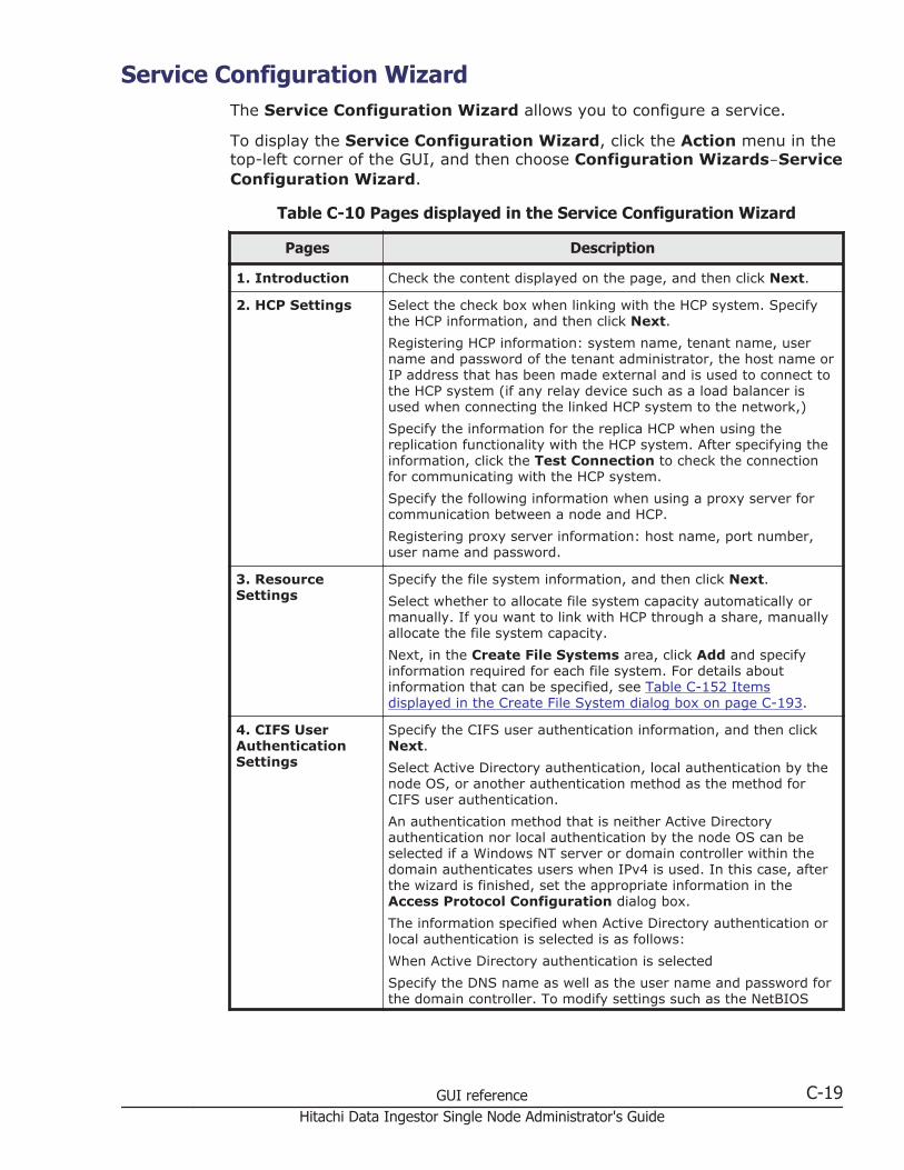
Service Configuration WizardThe Service Configuration Wizard allows you to configure a service.
To display the Service Configuration Wizard, click the Action menu in thetop-left corner of the GUI, and then choose Configuration Wizards-ServiceConfiguration Wizard.
Table C-10 Pages displayed in the Service Configuration Wizard
Pages Description
1. Introduction Check the content displayed on the page, and then click Next.
2. HCP Settings Select the check box when linking with the HCP system. Specifythe HCP information, and then click Next.
Registering HCP information: system name, tenant name, username and password of the tenant administrator, the host name orIP address that has been made external and is used to connect tothe HCP system (if any relay device such as a load balancer isused when connecting the linked HCP system to the network,)
Specify the information for the replica HCP when using thereplication functionality with the HCP system. After specifying theinformation, click the Test Connection to check the connectionfor communicating with the HCP system.
Specify the following information when using a proxy server forcommunication between a node and HCP.
Registering proxy server information: host name, port number,user name and password.
3. ResourceSettings
Specify the file system information, and then click Next.
Select whether to allocate file system capacity automatically ormanually. If you want to link with HCP through a share, manuallyallocate the file system capacity.
Next, in the Create File Systems area, click Add and specifyinformation required for each file system. For details aboutinformation that can be specified, see Table C-152 Itemsdisplayed in the Create File System dialog box on page C-193.
4. CIFS UserAuthenticationSettings
Specify the CIFS user authentication information, and then clickNext.
Select Active Directory authentication, local authentication by thenode OS, or another authentication method as the method forCIFS user authentication.
An authentication method that is neither Active Directoryauthentication nor local authentication by the node OS can beselected if a Windows NT server or domain controller within thedomain authenticates users when IPv4 is used. In this case, afterthe wizard is finished, set the appropriate information in theAccess Protocol Configuration dialog box.
The information specified when Active Directory authentication orlocal authentication is selected is as follows:
When Active Directory authentication is selected
Specify the DNS name as well as the user name and password forthe domain controller. To modify settings such as the NetBIOS
GUI reference C-19Hitachi Data Ingestor Single Node Administrator's Guide
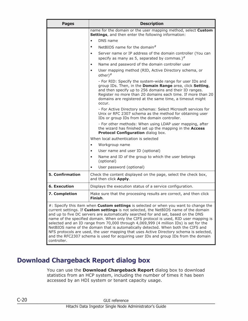
Pages Description
name for the domain or the user mapping method, select CustomSettings, and then enter the following information:
• DNS name
• NetBIOS name for the domain#
• Server name or IP address of the domain controller (You canspecify as many as 5, separated by commas.)#
• Name and password of the domain controller user
• User mapping method (RID, Active Directory schema, orother)#
- For RID: Specify the system-wide range for user IDs andgroup IDs. Then, in the Domain Range area, click Setting,and then specify up to 256 domains and their ID ranges.Register no more than 20 domains each time. If more than 20domains are registered at the same time, a timeout mightoccur.
- For Active Directory schemas: Select Microsoft services forUnix or RFC 2307 schema as the method for obtaining userIDs or group IDs from the domain controller.
- For other methods: When using LDAP user mapping, afterthe wizard has finished set up the mapping in the AccessProtocol Configuration dialog box.
When local authentication is selected
• Workgroup name
• User name and user ID (optional)
• Name and ID of the group to which the user belongs(optional)
• User password (optional)
5. Confirmation Check the content displayed on the page, select the check box,and then click Apply.
6. Execution Displays the execution status of a service configuration.
7. Completion Make sure that the processing results are correct, and then clickFinish.
#: Specify this item when Custom settings is selected or when you want to change thecurrent settings. If Custom settings is not selected, the NetBIOS name of the domainand up to five DC servers are automatically searched for and set, based on the DNSname of the specified domain. When only the CIFS protocol is used, RID user mapping isselected and an ID range from 70,000 through 4,069,999 (4 million IDs) is set for theNetBIOS name of the domain that is automatically detected. When both the CIFS andNFS protocols are used, the user mapping that uses Active Directory schema is selected,and the RFC2307 schema is used for acquiring user IDs and group IDs from the domaincontroller.
Download Chargeback Report dialog boxYou can use the Download Chargeback Report dialog box to downloadstatistics from an HCP system, including the number of times it has beenaccessed by an HDI system or tenant capacity usage.
C-20 GUI referenceHitachi Data Ingestor Single Node Administrator's Guide

Note: Information for each tenant is obtained from the HDI system. Fordetails about chargeback reports, contact the administrator of the HCPsystem.
To display the Download Chargeback Report dialog box, click the Actionmenu in the top-left corner of the GUI, and then choose ChargebackReport.
Table C-11 Items displayed in the Download Chargeback Report dialogbox
Item Description
Report interval Specifies the interval at which statistics are acquired.
DailyObtains the daily status.
HourlyObtains the hourly status.
Start date Specifies the start date of the period for which information isdownloaded.
End date Specifies the end date of the period for which information isdownloaded.
Download button Downloads information. A dialog for specifying the downloaddestination is displayed.
Import Files dialog boxYou can import files from the shared directory on the another file server tothe shared directory in the HDI system.
To display the Import Files dialog box, in the top-left corner of the GUI,choose Action, and then Import Files.
Tip: A maximum of 20 tasks for importing files can be executed at the sametime.
Table C-12 Operations that can be performed in the Import Files dialogbox
Operation Description See
Defining tasks You can define tasks for importing data.Specify information, such as a shareddirectory in the HDI system to whichfiles are to be imported, or the fileserver where the files to be importedare stored.
Table C-13 Itemsspecified when a task isdefined on page C-22
Verifying files You can verify whether the source filescan be imported.
Table C-14 Itemsdisplayed when files areverified on page C-24
GUI reference C-21Hitachi Data Ingestor Single Node Administrator's Guide

Operation Description See
Starting theimportation of files
You can import files on another fileserver to the HDI system.
Table C-15 Itemsdisplayed whenimportation of files startson page C-25
Checking files forwhich an erroroccurred
You can check whether there were anyerrors or cautions while files were beingverified or imported.
Table C-16 Itemsdisplayed in the ScanFailure List dialog box, theImport Failure List dialogbox, or the Read FailureList dialog box on pageC-28
Table C-18 Itemsdisplayed in the WarningList dialog box on pageC-29
Table C-13 Items specified when a task is defined
Item Description
Importtarget
Host name Specify an HDI node to which files are to be imported.
Share name Specify a shared directory in the HDI system to which filesare to be imported. Use the Select Share button to selectthe shared directory.
Export point The path to the shared directory is displayed.
Importsource
Host name Specify the host where the files to be imported are stored.
Protocol Select the protocol used for importing data.
Share name Specify the shared directory where the files to be importedare stored.
User name If CIFS is selected for Protocol, specify a user name to beused for connecting to the CIFS share where the files to beimported are stored.
Specify the user name using no more than 256 characters.You can use alphanumeric characters.
Password If CIFS is selected for Protocol, specify a password to beused for connecting to the CIFS share where the files to beimported are stored.
Specify the password using no more than 128 characters.You can use alphanumeric characters.
TestConnectionbutton
Checks whether the file share that has been specified asthe import-source is accessible.
CIFS ShareSettings
Nameresolution
If CIFS is selected for Protocol, specify how to access thefiles to be imported.
The system automatically switches the authenticationmethod. Local authentication, Active Directoryauthentication, and the default account are used to accessfiles in that order.
C-22 GUI referenceHitachi Data Ingestor Single Node Administrator's Guide
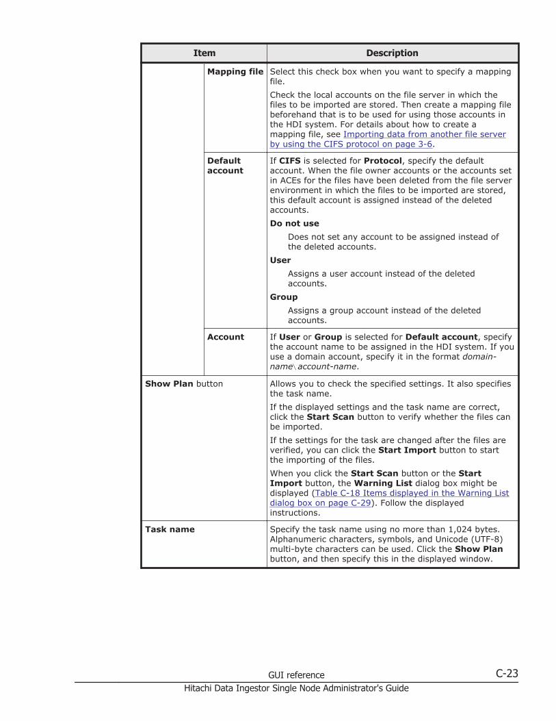
Item Description
Mapping file Select this check box when you want to specify a mappingfile.
Check the local accounts on the file server in which thefiles to be imported are stored. Then create a mapping filebeforehand that is to be used for using those accounts inthe HDI system. For details about how to create amapping file, see Importing data from another file serverby using the CIFS protocol on page 3-6.
Defaultaccount
If CIFS is selected for Protocol, specify the defaultaccount. When the file owner accounts or the accounts setin ACEs for the files have been deleted from the file serverenvironment in which the files to be imported are stored,this default account is assigned instead of the deletedaccounts.
Do not use
Does not set any account to be assigned instead ofthe deleted accounts.
User
Assigns a user account instead of the deletedaccounts.
Group
Assigns a group account instead of the deletedaccounts.
Account If User or Group is selected for Default account, specifythe account name to be assigned in the HDI system. If youuse a domain account, specify it in the format domain-name\account-name.
Show Plan button Allows you to check the specified settings. It also specifiesthe task name.
If the displayed settings and the task name are correct,click the Start Scan button to verify whether the files canbe imported.
If the settings for the task are changed after the files areverified, you can click the Start Import button to startthe importing of the files.
When you click the Start Scan button or the StartImport button, the Warning List dialog box might bedisplayed (Table C-18 Items displayed in the Warning Listdialog box on page C-29). Follow the displayedinstructions.
Task name Specify the task name using no more than 1,024 bytes.Alphanumeric characters, symbols, and Unicode (UTF-8)multi-byte characters can be used. Click the Show Planbutton, and then specify this in the displayed window.
GUI reference C-23Hitachi Data Ingestor Single Node Administrator's Guide
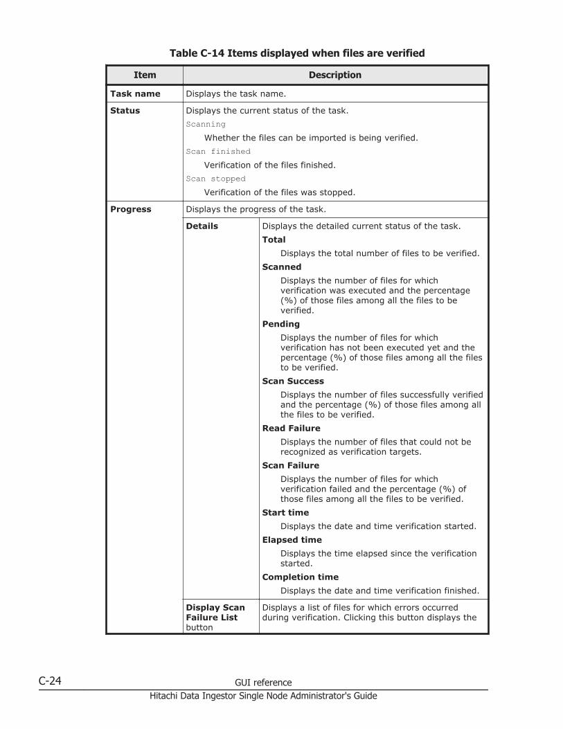
Table C-14 Items displayed when files are verified
Item Description
Task name Displays the task name.
Status Displays the current status of the task.
ScanningWhether the files can be imported is being verified.
Scan finishedVerification of the files finished.
Scan stoppedVerification of the files was stopped.
Progress Displays the progress of the task.
Details Displays the detailed current status of the task.
Total
Displays the total number of files to be verified.
Scanned
Displays the number of files for whichverification was executed and the percentage(%) of those files among all the files to beverified.
Pending
Displays the number of files for whichverification has not been executed yet and thepercentage (%) of those files among all the filesto be verified.
Scan Success
Displays the number of files successfully verifiedand the percentage (%) of those files among allthe files to be verified.
Read Failure
Displays the number of files that could not berecognized as verification targets.
Scan Failure
Displays the number of files for whichverification failed and the percentage (%) ofthose files among all the files to be verified.
Start time
Displays the date and time verification started.
Elapsed time
Displays the time elapsed since the verificationstarted.
Completion time
Displays the date and time verification finished.
Display ScanFailure Listbutton
Displays a list of files for which errors occurredduring verification. Clicking this button displays the
C-24 GUI referenceHitachi Data Ingestor Single Node Administrator's Guide

Item Description
Scan Failure List dialog box (Table C-16 Itemsdisplayed in the Scan Failure List dialog box, theImport Failure List dialog box, or the Read FailureList dialog box on page C-28).
Display ReadFailure Listbutton
Displays a list of files that could not be recognized asverification targets. Clicking this button displays theRead Failure List dialog box (Table C-16 Itemsdisplayed in the Scan Failure List dialog box, theImport Failure List dialog box, or the Read FailureList dialog box on page C-28).
More ActionsClick and choose the necessary operation.
Download Scan Failure List
Downloads a text file that contains a list of filesfor which errors occurred during verification.
Download Read Failure List
Downloads a text file that contains a list of filesthat could not be recognized as verificationtargets.
Settings Displays information (that was specified when the task was defined) ofthe shared directory to which the files are to be imported and of thefile server in which the files to be imported are stored.
CIFS ShareSettings
Displays the settings that were specified when the task was definedand that are used for importing data in the CIFS share.
Start Importbutton
Starts importing files. This button becomes active after the verificationof the files to be imported finishes.
Edit Settings &Start Importbutton
or
Edit Settings &Retry Scanbutton
Changes the task settings. Clicking this button displays the itemsshown in Table C-13 Items specified when a task is defined on pageC-22. Check and, if necessary, revise the settings. Then, click theShow Plan button and make sure that the settings are correct. Next,click the Start Import button to start importing files or click the StartScan button to re-execute verification of the files to be imported.When you click the Start Scan button or the Start Import button,the Warning List dialog box might be displayed (Table C-18 Itemsdisplayed in the Warning List dialog box on page C-29). Follow thedisplayed instructions.
You can click this button when Status is Scan finished or Scanstopped. If you want to change the task settings, wait until verificationfinishes, or click the Cancel Scan button to cancel verification.
Cancel Scanbutton
Cancels the verification of the files to be imported.
Table C-15 Items displayed when importation of files starts
Item Description
Task name Displays the task name.
Status Displays the current status of the task.
Importing
GUI reference C-25Hitachi Data Ingestor Single Node Administrator's Guide
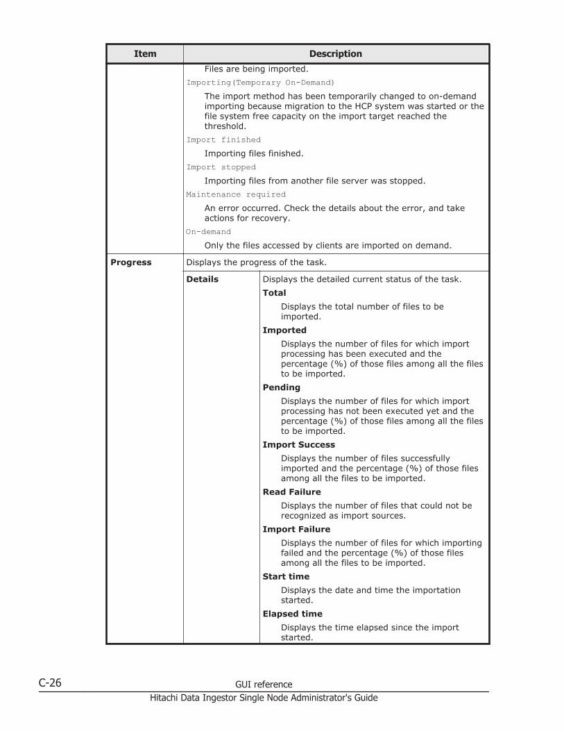
Item Description
Files are being imported.
Importing(Temporary On-Demand)The import method has been temporarily changed to on-demandimporting because migration to the HCP system was started or thefile system free capacity on the import target reached thethreshold.
Import finishedImporting files finished.
Import stoppedImporting files from another file server was stopped.
Maintenance requiredAn error occurred. Check the details about the error, and takeactions for recovery.
On-demandOnly the files accessed by clients are imported on demand.
Progress Displays the progress of the task.
Details Displays the detailed current status of the task.
Total
Displays the total number of files to beimported.
Imported
Displays the number of files for which importprocessing has been executed and thepercentage (%) of those files among all the filesto be imported.
Pending
Displays the number of files for which importprocessing has not been executed yet and thepercentage (%) of those files among all the filesto be imported.
Import Success
Displays the number of files successfullyimported and the percentage (%) of those filesamong all the files to be imported.
Read Failure
Displays the number of files that could not berecognized as import sources.
Import Failure
Displays the number of files for which importingfailed and the percentage (%) of those filesamong all the files to be imported.
Start time
Displays the date and time the importationstarted.
Elapsed time
Displays the time elapsed since the importstarted.
C-26 GUI referenceHitachi Data Ingestor Single Node Administrator's Guide
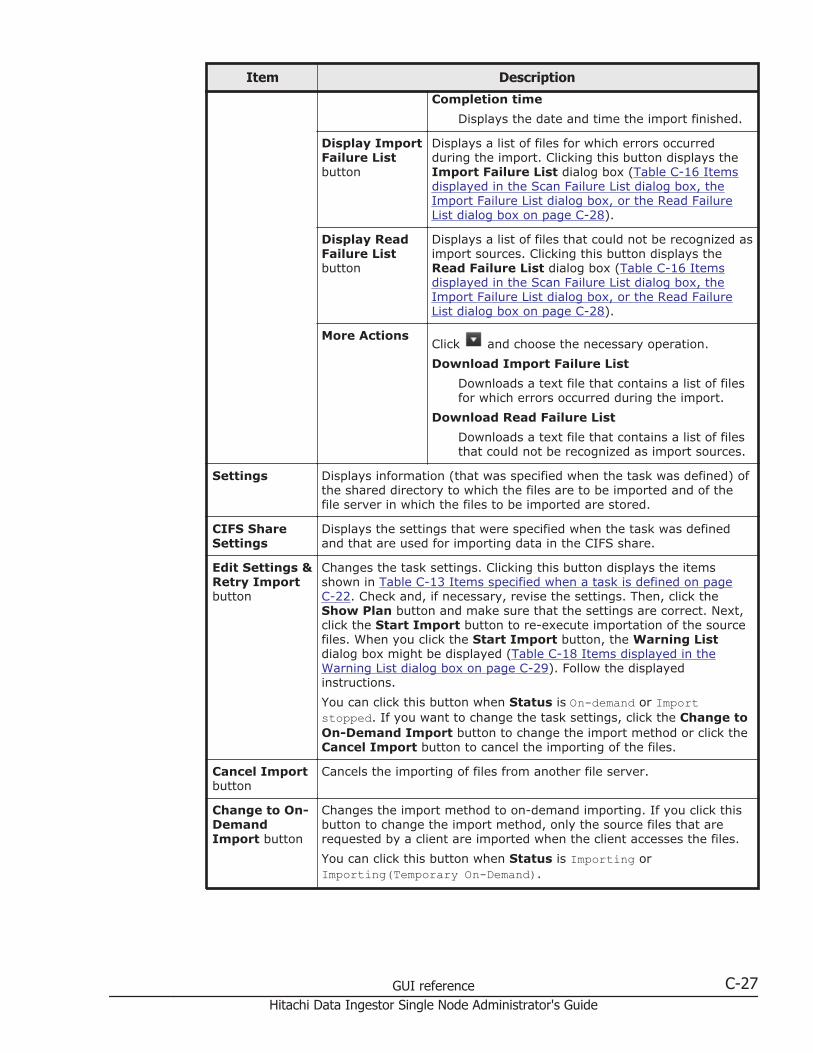
Item Description
Completion time
Displays the date and time the import finished.
Display ImportFailure Listbutton
Displays a list of files for which errors occurredduring the import. Clicking this button displays theImport Failure List dialog box (Table C-16 Itemsdisplayed in the Scan Failure List dialog box, theImport Failure List dialog box, or the Read FailureList dialog box on page C-28).
Display ReadFailure Listbutton
Displays a list of files that could not be recognized asimport sources. Clicking this button displays theRead Failure List dialog box (Table C-16 Itemsdisplayed in the Scan Failure List dialog box, theImport Failure List dialog box, or the Read FailureList dialog box on page C-28).
More ActionsClick and choose the necessary operation.
Download Import Failure List
Downloads a text file that contains a list of filesfor which errors occurred during the import.
Download Read Failure List
Downloads a text file that contains a list of filesthat could not be recognized as import sources.
Settings Displays information (that was specified when the task was defined) ofthe shared directory to which the files are to be imported and of thefile server in which the files to be imported are stored.
CIFS ShareSettings
Displays the settings that were specified when the task was definedand that are used for importing data in the CIFS share.
Edit Settings &Retry Importbutton
Changes the task settings. Clicking this button displays the itemsshown in Table C-13 Items specified when a task is defined on pageC-22. Check and, if necessary, revise the settings. Then, click theShow Plan button and make sure that the settings are correct. Next,click the Start Import button to re-execute importation of the sourcefiles. When you click the Start Import button, the Warning Listdialog box might be displayed (Table C-18 Items displayed in theWarning List dialog box on page C-29). Follow the displayedinstructions.
You can click this button when Status is On-demand or Importstopped. If you want to change the task settings, click the Change toOn-Demand Import button to change the import method or click theCancel Import button to cancel the importing of the files.
Cancel Importbutton
Cancels the importing of files from another file server.
Change to On-DemandImport button
Changes the import method to on-demand importing. If you click thisbutton to change the import method, only the source files that arerequested by a client are imported when the client accesses the files.
You can click this button when Status is Importing orImporting(Temporary On-Demand).
GUI reference C-27Hitachi Data Ingestor Single Node Administrator's Guide
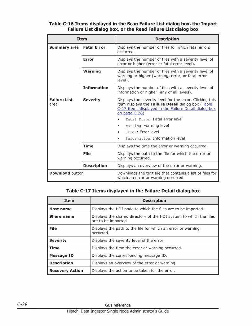
Table C-16 Items displayed in the Scan Failure List dialog box, the ImportFailure List dialog box, or the Read Failure List dialog box
Item Description
Summary area Fatal Error Displays the number of files for which fatal errorsoccurred.
Error Displays the number of files with a severity level oferror or higher (error or fatal error level).
Warning Displays the number of files with a severity level ofwarning or higher (warning, error, or fatal errorlevel).
Information Displays the number of files with a severity level ofinformation or higher (any of all levels).
Failure Listarea
Severity Displays the severity level for the error. Clicking thisitem displays the Failure Detail dialog box (TableC-17 Items displayed in the Failure Detail dialog boxon page C-28).
• Fatal Error: Fatal error level
• Warning: warning level
• Error: Error level
• Information: Information level
Time Displays the time the error or warning occurred.
File Displays the path to the file for which the error orwarning occurred.
Description Displays an overview of the error or warning.
Download button Downloads the text file that contains a list of files forwhich an error or warning occurred.
Table C-17 Items displayed in the Failure Detail dialog box
Item Description
Host name Displays the HDI node to which the files are to be imported.
Share name Displays the shared directory of the HDI system to which the filesare to be imported.
File Displays the path to the file for which an error or warningoccurred.
Severity Displays the severity level of the error.
Time Displays the time the error or warning occurred.
Message ID Displays the corresponding message ID.
Description Displays an overview of the error or warning.
Recovery Action Displays the action to be taken for the error.
C-28 GUI referenceHitachi Data Ingestor Single Node Administrator's Guide

Table C-18 Items displayed in the Warning List dialog box
Item Description
Message ID Displays the message ID indicating the contents of the warning.
Description Displays an explanation.
Edit Settingsbutton
Changes the task settings. Clicking this button displays the itemsshown in Table C-13 Items specified when a task is defined onpage C-22.
Start Scan button Verifies whether the files can be imported.
This button is displayed if the Warning List dialog box isdisplayed while you are verifying files.
Start Importbutton
Starts the importing of the files.
This button is displayed if the Warning List dialog box isdisplayed while you are importing files.
Configure Proxy Server dialog boxThis dialog box allows you to specify information about the proxy server to beused for communication between nodes and HCP.
To display the Configure Proxy Server dialog box, click the Action menu inthe top-left corner of the GUI, and then choose Configure Proxy Server.
Table C-19 Items displayed in the Configure Proxy Server dialog box
Item Description
Proxyserver
Use Select this if you want to use a proxy serverfor communication between nodes and HCP.
Host name Specify the host name of the proxy server.
Port Specify the port number to be used on theproxy server.
Userauthentication
User name If you are using a proxy server that requiresuser authentication, specify the user name.
Password If you are using a proxy server that requiresuser authentication, specify the password.
The entered password is displayed by usingasterisks (*).
Change User Password dialog boxIn the Change User Password dialog box, a system administrator canchange his or her own password.
GUI reference C-29Hitachi Data Ingestor Single Node Administrator's Guide

Note: The password set here is required for the operation and managementof the HDI system. Be sure not to forget this password.The password is shared with the HDI API administrator account. If thepassword is changed from the GUI, use the new password in the API.If the current password is lost, use the adminpasswd command to initializethe password and then specify a new password.
To display the Change User Password dialog box, click the Action menu inthe top-left corner of the GUI, choose Change Password, and then chooseChange User Password.
Table C-20 Items displayed in the Change User Password dialog box
Item Description
User name Displays the user name.
Currentpassword
Enter the current password.
The entered password is displayed by using asterisks (*).
New password Enter a new password in 256 or fewer characters. If you specify two ormore words as a password, delimit the words by a space.
You can use alphanumeric characters and the following symbols:
! # $ % & ' ( ) * + - . = @ \ ^ _ |Specify a new password that meets conditions set in the LoginSecurity dialog box, such as the minimum number of characters andcombination of the characters that can be used as a password. Fordetails about the Login Security dialog box, see Login Security dialogbox on page C-31.
The entered password is displayed by using asterisks (*).
Confirm newpassword
Enter the character string you entered for New password.
The entered password is displayed by using asterisks (*).
Update HCP Anywhere Credentials dialog boxThis dialog box allows you to change the password to be used for accessingHCP Anywhere.
To display the Update HCP Anywhere Credentials dialog box, click theAction menu in the top-left corner of the GUI, choose Change Password,and then choose Update HCP Anywhere Credentials.
Table C-21 Items displayed in the Update HCP Anywhere Credentialsdialog box
Item Description
Password Enter a new password.
The entered password is displayed by using asterisks (*).
C-30 GUI referenceHitachi Data Ingestor Single Node Administrator's Guide

Login Security dialog boxYou can change the timeout time, automatic account lock-related settings,and password policy for a system administrator account.
To display the Login Security dialog box, in the top-left corner of the GUI,choose Action and then Login Security.
Table C-22 Items displayed in the Login Security dialog box
Item Description
Session timeout Specify the session timeout time in minutes. If youdo not want to limit the timeout time, specify 0.
Passwordpolicy
Enableaccountlockout
Select Yes check box to enable auto-locking ofaccounts.
An account will be locked when the number ofconsecutive unsuccessful log on attempts exceedsthe number specified in Maximum number oflogin attempts.
Maximum number of login attempts
Specify the number of consecutive unsuccessfullog on attempts allowed before an account islocked. The specified value must be in the rangefrom 1 to 100.
Time at which to cancel account lockout
Specify the length of time (in minutes) beforeunlocking the automatically locked account. Thespecified value must be in the range from 1 to999.
Minimumlength
Specify the minimum number of characters for apassword in the range from 1 to 256.
Minimumnumber ofcharacters
Specify the conditions for the combinations ofcharacters that can be used for a password.
Uppercase
Specify the minimum number of uppercasecharacters that must be included in a passwordin the range from 0 to 256. If you do not wantto limit the number of uppercase characters,specify 0.
Lowercase
Specify the minimum number of lowercasecharacters that must be included in a passwordin the range from 0 to 256. If you do not wantto limit the number of lowercase characters,specify 0.
Numbers
Specify the minimum number of numericcharacters that must be included in a passwordin the range from 0 to 256. If you do not wantto limit the number of numeric characters,specify 0.
GUI reference C-31Hitachi Data Ingestor Single Node Administrator's Guide
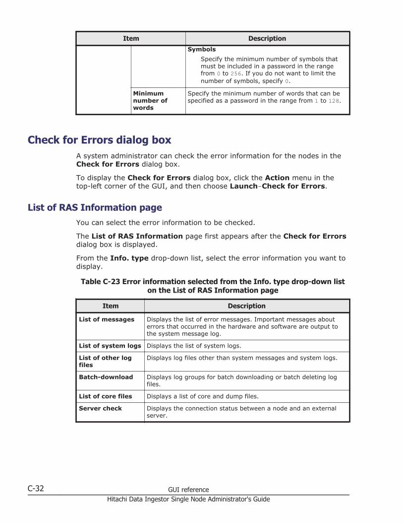
Item Description
Symbols
Specify the minimum number of symbols thatmust be included in a password in the rangefrom 0 to 256. If you do not want to limit thenumber of symbols, specify 0.
Minimumnumber ofwords
Specify the minimum number of words that can bespecified as a password in the range from 1 to 128.
Check for Errors dialog boxA system administrator can check the error information for the nodes in theCheck for Errors dialog box.
To display the Check for Errors dialog box, click the Action menu in thetop-left corner of the GUI, and then choose Launch-Check for Errors.
List of RAS Information pageYou can select the error information to be checked.
The List of RAS Information page first appears after the Check for Errorsdialog box is displayed.
From the Info. type drop-down list, select the error information you want todisplay.
Table C-23 Error information selected from the Info. type drop-down liston the List of RAS Information page
Item Description
List of messages Displays the list of error messages. Important messages abouterrors that occurred in the hardware and software are output tothe system message log.
List of system logs Displays the list of system logs.
List of other logfiles
Displays log files other than system messages and system logs.
Batch-download Displays log groups for batch downloading or batch deleting logfiles.
List of core files Displays a list of core and dump files.
Server check Displays the connection status between a node and an externalserver.
C-32 GUI referenceHitachi Data Ingestor Single Node Administrator's Guide

List of RAS Information page (for List of messages)
The List of RAS Information page (for List of messages) displays thesystem message. For the system message, important messages related toerrors occurring in the hardware or software are output.
To view past system messages, select a file for list generation from the Filesdrop-down list, and then click the Display button on the right of the page. Tonarrow down the displayed messages by severity level, select the severitylevel from the Conditions drop-down list, and then click the Display buttonon the right of the page.
To display the List of RAS Information page (for List of messages), inthe Check for Errors dialog box, select List of messages from the Info.type drop-down list on the List of RAS Information page, and then clickDisplay.
Table C-24 Items displayed on the List of RAS Information page (for List ofmessages)
Item Description
Info. typedrop-down list
Select the type of information to be displayed. For details about theitems displayed, see Table C-23 Error information selected from theInfo. type drop-down list on the List of RAS Information page on pageC-32.
Files drop-downlist
Select the message file to be displayed.
• em_alertfile
Displays the latest error messages.
• em_alertfile.generation-number
Displays messages about past errors.
Saved messages, such as em_alertfile.1 or em_alertfile.2, canbe selected. The larger the generation number, the older themessages. Note that 0 might be suffixed to the file name,depending on the system status.
Conditionsdrop-down list
Narrow down the messages to be displayed by severity level.
• Information
Select this option to display messages at the information andhigher levels (all levels).
• Warning
Select this option to display messages at the warning and higherlevels (warning, error, and fatal error levels).
• Error
Select this option to display messages at the error and higherlevel (error and fatal error levels).
• Fatal error
Select this option to display messages at the fatal error level only.
Display button Displays the messages.
Importance Displays messages by severity level.
• Information
GUI reference C-33Hitachi Data Ingestor Single Node Administrator's Guide
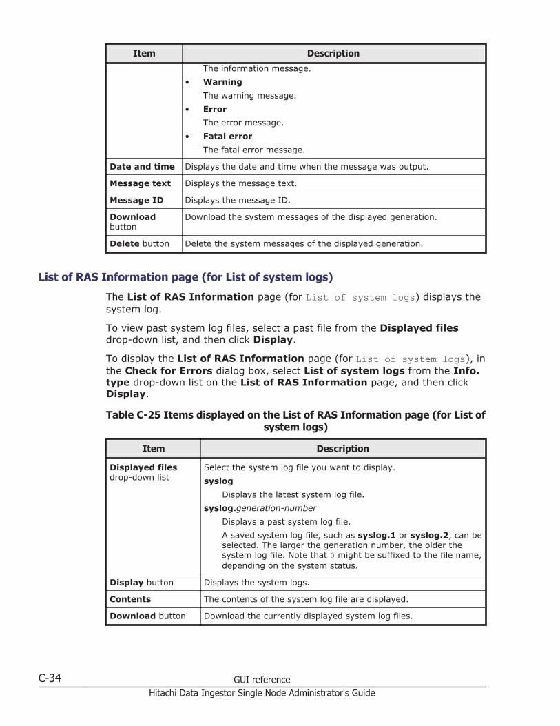
Item Description
The information message.
• Warning
The warning message.
• Error
The error message.
• Fatal error
The fatal error message.
Date and time Displays the date and time when the message was output.
Message text Displays the message text.
Message ID Displays the message ID.
Downloadbutton
Download the system messages of the displayed generation.
Delete button Delete the system messages of the displayed generation.
List of RAS Information page (for List of system logs)
The List of RAS Information page (for List of system logs) displays thesystem log.
To view past system log files, select a past file from the Displayed filesdrop-down list, and then click Display.
To display the List of RAS Information page (for List of system logs), inthe Check for Errors dialog box, select List of system logs from the Info.type drop-down list on the List of RAS Information page, and then clickDisplay.
Table C-25 Items displayed on the List of RAS Information page (for List ofsystem logs)
Item Description
Displayed filesdrop-down list
Select the system log file you want to display.
syslog
Displays the latest system log file.
syslog.generation-number
Displays a past system log file.
A saved system log file, such as syslog.1 or syslog.2, can beselected. The larger the generation number, the older thesystem log file. Note that 0 might be suffixed to the file name,depending on the system status.
Display button Displays the system logs.
Contents The contents of the system log file are displayed.
Download button Download the currently displayed system log files.
C-34 GUI referenceHitachi Data Ingestor Single Node Administrator's Guide

Item Description
Delete button Delete the currently displayed system log files.
List of RAS Information page (for List of other log files)
The List of RAS Information page (for List of other log files) displaysthe log files that are not system messages or system logs.
When you select the type of log file from the File type drop-down list andthen click Display, the latest information for the selected log file is displayed.To view past log files, select a specific past file from the Displayed filesdrop-down list, and then click Display. For past log files, a generationnumber is added to the end of the name or before the file extension. Thelarger the generation number becomes, the older the log file.
To display the List of RAS Information page (for List of other logfiles), in the Check for Errors dialog box, select List of other log filesfrom the Info. type drop-down list on the List of RAS Information page,and then click Display.
Table C-26 Items displayed on the List of RAS Information page (for List ofother log files)
Item Description
File type drop-downlist
Select the type of the log file you want to display.
Displayed files drop-down list
Select the log file you want to display.
Display button Displays the log files.
Contents The contents of the log file selected from the File type drop-down list and the Displayed files drop-down list are displayed.
Download button Download the log files of the displayed generation.
Delete button Delete the log files of the displayed generation.
Note that Delete is not displayed for some log files, and youcannot delete these log files.
List of RAS Information page (for Batch-download)
You can download and delete log files in a batch operation.
To display the List of RAS Information page (for Batch-download), in theCheck for Errors dialog box, select Batch-download from the Info. typedrop-down list on the List of RAS Information page, and then clickDisplay.
GUI reference C-35Hitachi Data Ingestor Single Node Administrator's Guide

Table C-27 Items displayed on the List of RAS Information page (forBatch-download)
Item Description
Radio button Select a log group to download.
Log group Displays log names of groups.
File type Displays the types of log files that belong to a log group.
Number offiles
Displays the total number of log files currently saved (the total numberof the latest log file and the past log files).
Explanation Displays the description of a log file.
Downloadbutton
Batch download all past log files that belong to the log group selected.
In batch downloading, log files are archived by tar and compressed bygzip.
When you perform batch downloading, some data might be missed ifthe disk selected to store the Temporary Internet files folder forInternet Explorer has insufficient space. In this situation, InternetExplorer does not generate an error or message.
Delete button Batch delete all past log files that belong to the log group selected.
List of RAS Information page (for List of core files)
The List of RAS Information page (for List of core files) displays corefiles and dump files.
To display the List of RAS Information page (for List of core files), inthe Check for Errors dialog box, select List of core files from the Info.type drop-down list on the List of RAS Information page, and then clickDisplay.
Note:
• Expired core files are deleted automatically. If a core file is generated,download it and send it to maintenance personnel.
• Delete downloaded core files manually.
• The dump files are listed along with the core files if the OS dump files areoutput. A dump file is required only when the vendor requests you tocollect dump files. In such a case, download dump files and then contactmaintenance personnel. Also, there are three levels of dump files, 1, 3,and 4. The names of dump files contain a string such as the following:lvdump-file-level (1, 3, or 4)
Maintenance personnel can obtain level 1 files, but cannot obtain level 3or 4 files because they contain access data for the file system (NFS andCIFS services). Depending on the error level, you might be asked bymaintenance personnel to collect dump files, but since level 3 and 4 dumpfiles contain user information, be especially careful when managing thesefiles.
C-36 GUI referenceHitachi Data Ingestor Single Node Administrator's Guide
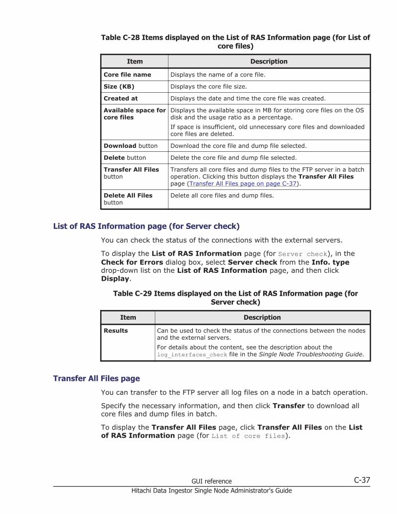
Table C-28 Items displayed on the List of RAS Information page (for List ofcore files)
Item Description
Core file name Displays the name of a core file.
Size (KB) Displays the core file size.
Created at Displays the date and time the core file was created.
Available space forcore files
Displays the available space in MB for storing core files on the OSdisk and the usage ratio as a percentage.
If space is insufficient, old unnecessary core files and downloadedcore files are deleted.
Download button Download the core file and dump file selected.
Delete button Delete the core file and dump file selected.
Transfer All Filesbutton
Transfers all core files and dump files to the FTP server in a batchoperation. Clicking this button displays the Transfer All Filespage (Transfer All Files page on page C-37).
Delete All Filesbutton
Delete all core files and dump files.
List of RAS Information page (for Server check)
You can check the status of the connections with the external servers.
To display the List of RAS Information page (for Server check), in theCheck for Errors dialog box, select Server check from the Info. typedrop-down list on the List of RAS Information page, and then clickDisplay.
Table C-29 Items displayed on the List of RAS Information page (forServer check)
Item Description
Results Can be used to check the status of the connections between the nodesand the external servers.
For details about the content, see the description about thelog_interfaces_check file in the Single Node Troubleshooting Guide.
Transfer All Files page
You can transfer to the FTP server all log files on a node in a batch operation.
Specify the necessary information, and then click Transfer to download allcore files and dump files in batch.
To display the Transfer All Files page, click Transfer All Files on the Listof RAS Information page (for List of core files).
GUI reference C-37Hitachi Data Ingestor Single Node Administrator's Guide

Table C-30 Items displayed on the Transfer All Files page
Item Description
FTP Server Specify the IP address or the host name of the FTP server.
User name Specify the name of the user who logs on to the FTP server.
Password Specify the password of the user.
Directory Specify the directory of the transfer destination. You cannot specify acharacter string including non-ASCII characters.
Create a directory on the FTP server before transferring files.
Transfer button Transfer all log files to the FTP server in a batch operation.
Dashboard tabIn the Dashboard tab, a system administrator can understand the overallstatus of the system.
To display the Dashboard tab, choose Dashboard in the top-left corner ofthe GUI.
Table C-31 Items displayed in the Dashboard tab
Item Description See
DashboardSettings button
Click this button to change the panelsdisplayed in the Dashboard tab.
Panel Configurationdialog box on pageC-44
SystemInformation
Displays information such as the nodestatus and system version.
System Informationpanel on page C-39
C-38 GUI referenceHitachi Data Ingestor Single Node Administrator's Guide
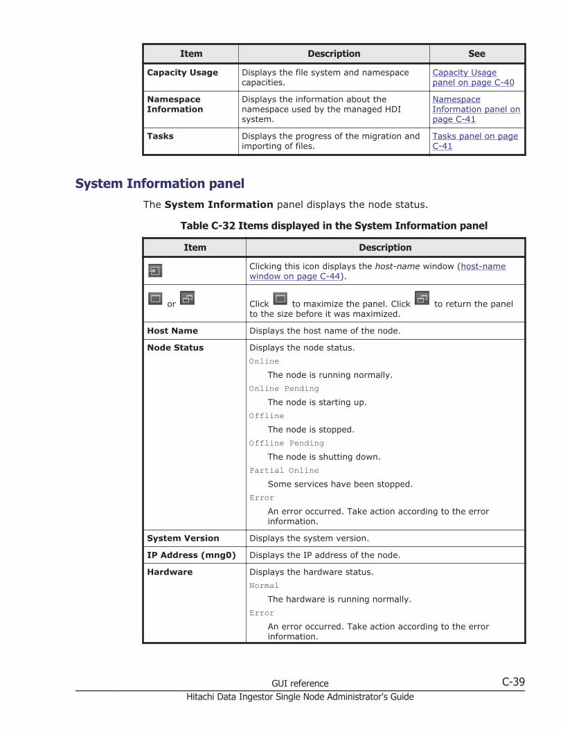
Item Description See
Capacity Usage Displays the file system and namespacecapacities.
Capacity Usagepanel on page C-40
NamespaceInformation
Displays the information about thenamespace used by the managed HDIsystem.
NamespaceInformation panel onpage C-41
Tasks Displays the progress of the migration andimporting of files.
Tasks panel on pageC-41
System Information panelThe System Information panel displays the node status.
Table C-32 Items displayed in the System Information panel
Item Description
Clicking this icon displays the host-name window (host-namewindow on page C-44).
or Click to maximize the panel. Click to return the panelto the size before it was maximized.
Host Name Displays the host name of the node.
Node Status Displays the node status.
OnlineThe node is running normally.
Online PendingThe node is starting up.
OfflineThe node is stopped.
Offline PendingThe node is shutting down.
Partial OnlineSome services have been stopped.
ErrorAn error occurred. Take action according to the errorinformation.
System Version Displays the system version.
IP Address (mng0) Displays the IP address of the node.
Hardware Displays the hardware status.
NormalThe hardware is running normally.
ErrorAn error occurred. Take action according to the errorinformation.
GUI reference C-39Hitachi Data Ingestor Single Node Administrator's Guide

Item DescriptionUnknown error
An error occurred for which information cannot be obtained.
Last System BackupDate
Displays the date and time the system configuration informationwas saved.
Displays Now saving if the system configuration information isbeing saved. Displays Not saving if the system configurationinformation is not saved.
Local DataEncryption Enabled
Displays whether encryption is used if an encryption license isset.
Capacity Usage panelThe Capacity Usage panel displays the file system and namespacecapacities.
Table C-33 Items displayed in the Capacity Usage panel
Item Description
Clicking this icon displays the File Systems window (FileSystems window on page C-49).
or Click to maximize the panel. Click to return the panelto the size before it was maximized.
File SystemUsage
Pie graph Displays the capacity allocated to file systems as usage.
Table HDI -host-name
Displays the host name for HDI.
Cache Total
Displays the total capacity of volume groups that can beused for file systems.
Allocated Capacity
Displays the amount of total volume group capacityallocated to file systems as a percentage.
NamespaceUsage
Pie graph Displays namespace usage.
Table Tenant - tenant-name
Displays the tenant name.
Quota
Displays the total capacity of the tenant.
Storage Capacity Used
Displays the tenant capacity usage.
C-40 GUI referenceHitachi Data Ingestor Single Node Administrator's Guide
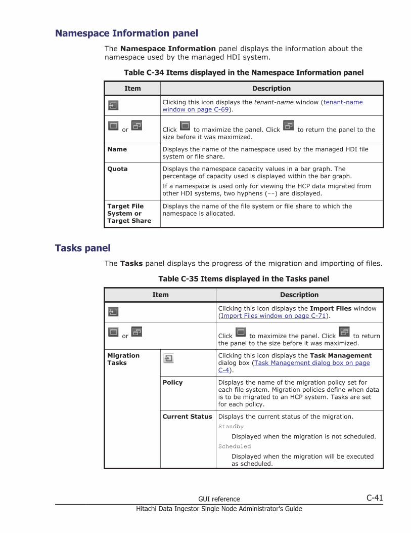
Namespace Information panelThe Namespace Information panel displays the information about thenamespace used by the managed HDI system.
Table C-34 Items displayed in the Namespace Information panel
Item Description
Clicking this icon displays the tenant-name window (tenant-namewindow on page C-69).
or Click to maximize the panel. Click to return the panel to thesize before it was maximized.
Name Displays the name of the namespace used by the managed HDI filesystem or file share.
Quota Displays the namespace capacity values in a bar graph. Thepercentage of capacity used is displayed within the bar graph.
If a namespace is used only for viewing the HCP data migrated fromother HDI systems, two hyphens (--) are displayed.
Target FileSystem orTarget Share
Displays the name of the file system or file share to which thenamespace is allocated.
Tasks panelThe Tasks panel displays the progress of the migration and importing of files.
Table C-35 Items displayed in the Tasks panel
Item Description
Clicking this icon displays the Import Files window(Import Files window on page C-71).
or Click to maximize the panel. Click to returnthe panel to the size before it was maximized.
MigrationTasks
Clicking this icon displays the Task Managementdialog box (Task Management dialog box on pageC-4).
Policy Displays the name of the migration policy set foreach file system. Migration policies define when datais to be migrated to an HCP system. Tasks are setfor each policy.
Current Status Displays the current status of the migration.
StandbyDisplayed when the migration is not scheduled.
ScheduledDisplayed when the migration will be executedas scheduled.
GUI reference C-41Hitachi Data Ingestor Single Node Administrator's Guide
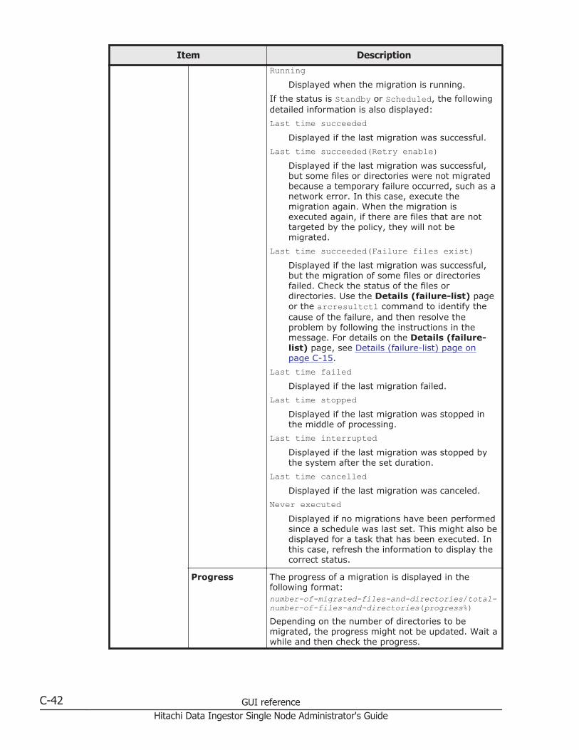
Item DescriptionRunning
Displayed when the migration is running.
If the status is Standby or Scheduled, the followingdetailed information is also displayed:
Last time succeededDisplayed if the last migration was successful.
Last time succeeded(Retry enable)Displayed if the last migration was successful,but some files or directories were not migratedbecause a temporary failure occurred, such as anetwork error. In this case, execute themigration again. When the migration isexecuted again, if there are files that are nottargeted by the policy, they will not bemigrated.
Last time succeeded(Failure files exist)Displayed if the last migration was successful,but the migration of some files or directoriesfailed. Check the status of the files ordirectories. Use the Details (failure-list) pageor the arcresultctl command to identify thecause of the failure, and then resolve theproblem by following the instructions in themessage. For details on the Details (failure-list) page, see Details (failure-list) page onpage C-15.
Last time failedDisplayed if the last migration failed.
Last time stoppedDisplayed if the last migration was stopped inthe middle of processing.
Last time interruptedDisplayed if the last migration was stopped bythe system after the set duration.
Last time cancelledDisplayed if the last migration was canceled.
Never executedDisplayed if no migrations have been performedsince a schedule was last set. This might also bedisplayed for a task that has been executed. Inthis case, refresh the information to display thecorrect status.
Progress The progress of a migration is displayed in thefollowing format:number-of-migrated-files-and-directories/total-number-of-files-and-directories(progress%)Depending on the number of directories to bemigrated, the progress might not be updated. Wait awhile and then check the progress.
C-42 GUI referenceHitachi Data Ingestor Single Node Administrator's Guide

Item Description
A hyphen (-) is displayed if the task is not running.In addition, one of the following statuses might bedisplayed instead of the progress:
0/calculating (-)Displayed when the number of files anddirectories to be migrated is being counted.
If you perform a task for a file system thatcontains a million or more files and directories,the status might not change from the state inwhich files and directories are being counted.Take action according to the note in Table C-1Items displayed on the Task List page in theTask Management dialog box on page C-4.
post-command executingDisplayed when file system quota information isbeing backed up.
waitingDisplayed when the task is waiting to beexecuted or when the status of the task ischanging. Wait a while, and then update thisinformation. If the status does not change, thenumber of tasks being executed at the sametime might have reached the maximum. Edittask schedules so that many tasks are notexecuted at the same time.
Last End Time Displays the date and time the last executedmigration task finished.
Number ofErrors
Displays the number of files and directories forwhich migration failed for the most recent migrationtask displayed.
Import-FileTasks
Clicking this icon displays the Import Files window(Import Files window on page C-71).
Task status Displays the number of tasks in each of the followingstatuses among the tasks for importing files fromanother file server:
Scanning
Whether the files can be imported is beingverified.
Scan finished
Verification of the files finished.
Importing
Files are being imported.
Import finished
Importing of files has finished.
GUI reference C-43Hitachi Data Ingestor Single Node Administrator's Guide
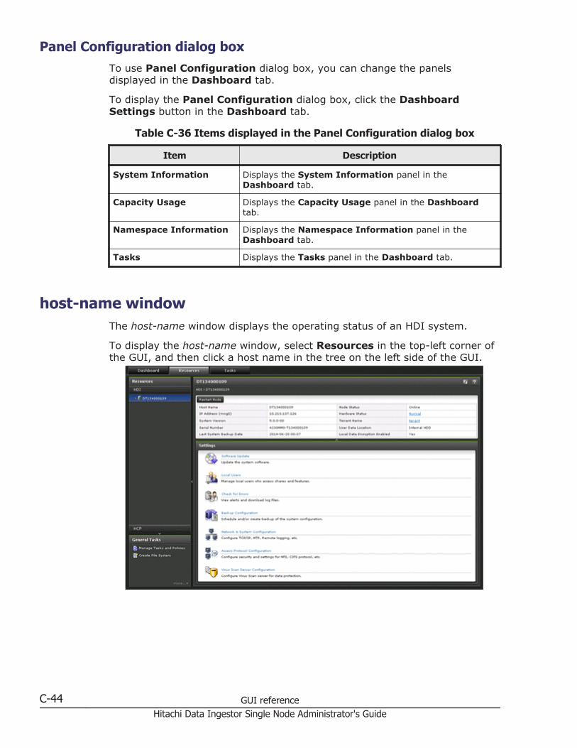
Panel Configuration dialog boxTo use Panel Configuration dialog box, you can change the panelsdisplayed in the Dashboard tab.
To display the Panel Configuration dialog box, click the DashboardSettings button in the Dashboard tab.
Table C-36 Items displayed in the Panel Configuration dialog box
Item Description
System Information Displays the System Information panel in theDashboard tab.
Capacity Usage Displays the Capacity Usage panel in the Dashboardtab.
Namespace Information Displays the Namespace Information panel in theDashboard tab.
Tasks Displays the Tasks panel in the Dashboard tab.
host-name windowThe host-name window displays the operating status of an HDI system.
To display the host-name window, select Resources in the top-left corner ofthe GUI, and then click a host name in the tree on the left side of the GUI.
C-44 GUI referenceHitachi Data Ingestor Single Node Administrator's Guide

Table C-37 Items displayed in the host-name window
Item Description
Restart Node button Restarts the node, and displays the Restart Nodedialog box (Restart Node dialog box on page C-74).
Host Name Displays the host name.
IP Address (mng0) Displays the IP address.
System Version Displays version information for the system.
Serial Number Displays the device identification number.
Last System Backup Date Displays the date and time when the systemconfiguration information is saved.
Displays Now saving if the system configurationinformation is being saved. Displays Not saving if thesystem configuration information is not saved.
Node Status Displays the node status.
OnlineThe node is running normally.
Online PendingThe node is starting up.
OfflineThe node is stopped.
Offline PendingThe node is shutting down.
Partial OnlineSome services have been stopped.
ErrorAn error occurred. Take action according to theerror information.
Hardware Status Displays the hardware status.
NormalThe hardware is running normally.
ErrorAn error occurred. Take action according to theerror information.
Unknown errorAn error occurred for which information cannot beobtained.
Tenant Name Displays the tenant name.
User Data Location Displays the storage location of the user data.
Internal HDDStored on the internal hard disk.
Storage systemStored in storage systems.
GUI reference C-45Hitachi Data Ingestor Single Node Administrator's Guide

Item DescriptionInternal HDD and Storage system
Stored on the internal hard disk and in storagesystems.
Local Data EncryptionEnabled
Displays whether encryption is used if an encryptionlicense is set.
Settingsarea
Software Update Updates the software running on the node. Clickingthis menu displays the System SoftwareInstallation dialog box (System Software Installationdialog box on page C-75).
Local Users Manages the information about the users who canaccess a file system. Clicking this menu displays theLocal Users dialog box (Local Users dialog box onpage C-75).
Check for Errors Checks the error information for the node. Clicking thismenu displays the Check for Errors dialog box(Check for Errors dialog box on page C-32).
BackupConfiguration
Downloads the system configuration file and uploadsthe downloaded system configuration file. Clicking thismenu displays the Backup Configuration dialog box(Backup Configuration dialog box on page C-87).
Network & SystemConfiguration
Changes the network and system configurations.Clicking this menu displays the Network & SystemConfiguration dialog box (Network & SystemConfiguration dialog box on page C-93).
Access ProtocolConfiguration
Performs operations such as changing the clientauthentication method. Clicking this menu displays theAccess Protocol Configuration dialog box (AccessProtocol Configuration dialog box on page C-121).
Virus Scan ServerConfiguration
Registers the scan server and sets scan conditions forreal-time scans. Clicking this menu displays the VirusScan Server Configuration dialog box (Virus ScanServer Configuration dialog box on page C-167).
Shares windowThe Shares window displays a list of file shares.
To display the Shares window, select Resources in the top-left corner of theGUI, select the triangle icon next to a host name in the tree on the left side ofthe GUI, and then click Shares.
C-46 GUI referenceHitachi Data Ingestor Single Node Administrator's Guide
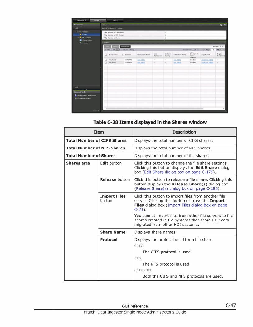
Table C-38 Items displayed in the Shares window
Item Description
Total Number of CIFS Shares Displays the total number of CIFS shares.
Total Number of NFS Shares Displays the total number of NFS shares.
Total Number of Shares Displays the total number of file shares.
Shares area Edit button Click this button to change the file share settings.Clicking this button displays the Edit Share dialogbox (Edit Share dialog box on page C-179).
Release button Click this button to release a file share. Clicking thisbutton displays the Release Share(s) dialog box(Release Share(s) dialog box on page C-183).
Import Filesbutton
Click this button to import files from another fileserver. Clicking this button displays the ImportFiles dialog box (Import Files dialog box on pageC-21).
You cannot import files from other file servers to fileshares created in file systems that share HCP datamigrated from other HDI systems.
Share Name Displays share names.
Protocol Displays the protocol used for a file share.
CIFSThe CIFS protocol is used.
NFSThe NFS protocol is used.
CIFS,NFSBoth the CIFS and NFS protocols are used.
GUI reference C-47Hitachi Data Ingestor Single Node Administrator's Guide

Item Description
File SystemName
Displays the name of the file system in which the fileshare is created. Clicking the name of a file systemopens the file-system-name window for the filesystem (file-system-name window on page C-53).
UseNamespace
Displays whether the HCP namespace is allocated tothe share.
If a file system is not linked to the HCP system atthe share level, two hyphens (--) are displayed.
ContentSharing
Displays how the HCP data is shared.
OffData in the share is migrated to the HCPsystem. HCP data migrated from other HDIsystems is not shared.
OnHCP data migrated from other HDI systems ismade public as read-only.
If the share is not linked to the HCP system at theshare level, two hyphens (--) are displayed.
CIFS ShareName
Displays CIFS share names. Clicking a CIFS sharename displays the CIFS Protocol Settings dialogbox (CIFS Protocol Settings dialog box on pageC-177). If the CIFS protocol is not used, two hyphens(--) are displayed.
Auto Creationof HomeDirectory
Displays whether the function for automaticallycreating a home directory is used in the CIFS share.
Export Point Displays the absolute path to the shared directory.Clicking the absolute path when the settings arespecified to use the NFS protocol displays the NFSProtocol Settings dialog box (NFS ProtocolSettings dialog box on page C-178).
TargetNamespace
Displays the name of the namespace allocated to theshare.
To check the status of the migration-destinationnamespace, click namespace-name to display thetenant-name window (tenant-name window on pageC-69).
If the namespace is not allocated to the share, twohyphens (--) are displayed.
External HCPHost Name
If HCP data is made available as read-only at theshare level, the host name or IP address that hasbeen made external and is used to connect to theHCP system is displayed.
If no host name or IP address is specified, twohyphens (--) are displayed.
Namespace-accessAccount
Displays the user name of the account used forviewing the namespace for making HCP data
C-48 GUI referenceHitachi Data Ingestor Single Node Administrator's Guide

Item Description
migrated from other HDI systems public as read-only.
This item is displayed if HCP data is made availableas read-only or if data that is to be made availableon other HDI systems is migrated to the HCP systemat the share level.
ReplicaSystem Name
If replica HCP system information is specified at theshare level, the name of the replica HCP system isdisplayed.
ExternalReplica HCPHost Name
If replica HCP system information is specified at theshare level, the host name or IP address that hasbeen made external and is used to connect to thereplica HCP system is displayed.
If no host name or IP address is specified, twohyphens (--) are displayed.
File Systems windowThe File Systems window displays the status of all files systems.
To display the File Systems window, select Resources in the top-left cornerof the GUI, select the triangle icon next to a host name in the tree on the leftside of the GUI, and then click File Systems.
Table C-39 Items displayed in the File Systems window
Item Description See
No. of FileSystems
Displays the total number of file systems. --
GUI reference C-49Hitachi Data Ingestor Single Node Administrator's Guide
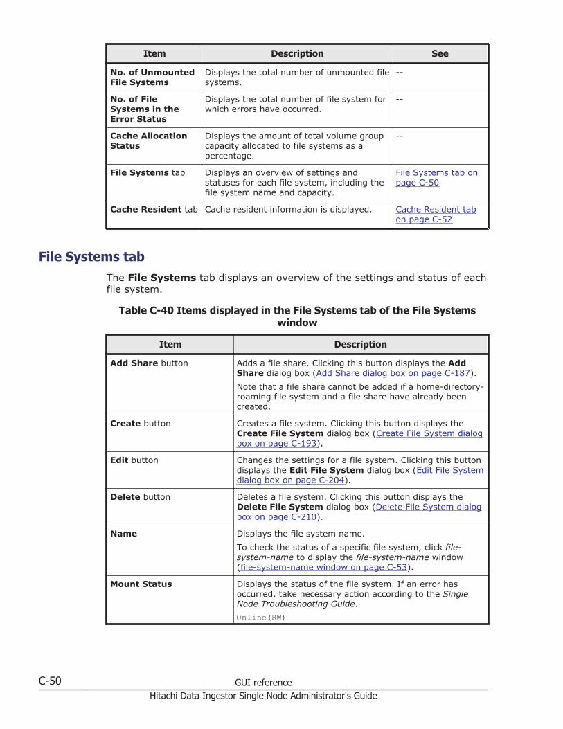
Item Description See
No. of UnmountedFile Systems
Displays the total number of unmounted filesystems.
--
No. of FileSystems in theError Status
Displays the total number of file system forwhich errors have occurred.
--
Cache AllocationStatus
Displays the amount of total volume groupcapacity allocated to file systems as apercentage.
--
File Systems tab Displays an overview of settings andstatuses for each file system, including thefile system name and capacity.
File Systems tab onpage C-50
Cache Resident tab Cache resident information is displayed. Cache Resident tabon page C-52
File Systems tabThe File Systems tab displays an overview of the settings and status of eachfile system.
Table C-40 Items displayed in the File Systems tab of the File Systemswindow
Item Description
Add Share button Adds a file share. Clicking this button displays the AddShare dialog box (Add Share dialog box on page C-187).
Note that a file share cannot be added if a home-directory-roaming file system and a file share have already beencreated.
Create button Creates a file system. Clicking this button displays theCreate File System dialog box (Create File System dialogbox on page C-193).
Edit button Changes the settings for a file system. Clicking this buttondisplays the Edit File System dialog box (Edit File Systemdialog box on page C-204).
Delete button Deletes a file system. Clicking this button displays theDelete File System dialog box (Delete File System dialogbox on page C-210).
Name Displays the file system name.
To check the status of a specific file system, click file-system-name to display the file-system-name window(file-system-name window on page C-53).
Mount Status Displays the status of the file system. If an error hasoccurred, take necessary action according to the SingleNode Troubleshooting Guide.
Online(RW)
C-50 GUI referenceHitachi Data Ingestor Single Node Administrator's Guide
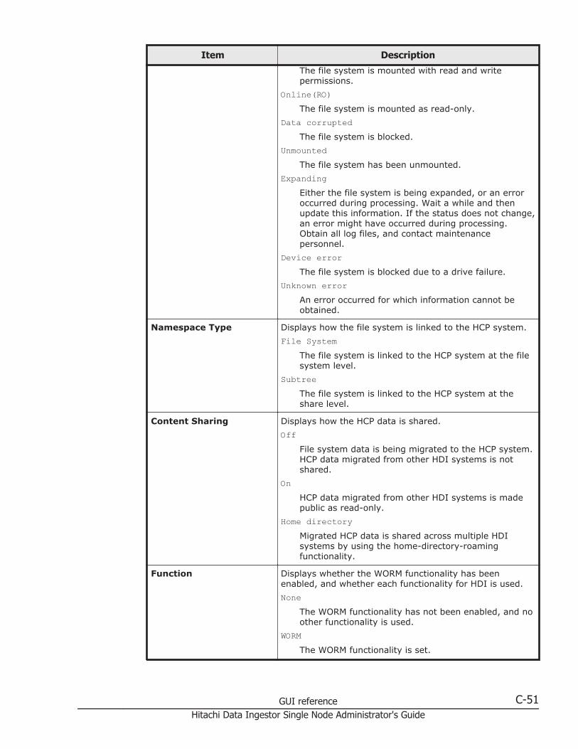
Item Description
The file system is mounted with read and writepermissions.
Online(RO)The file system is mounted as read-only.
Data corruptedThe file system is blocked.
UnmountedThe file system has been unmounted.
ExpandingEither the file system is being expanded, or an erroroccurred during processing. Wait a while and thenupdate this information. If the status does not change,an error might have occurred during processing.Obtain all log files, and contact maintenancepersonnel.
Device errorThe file system is blocked due to a drive failure.
Unknown errorAn error occurred for which information cannot beobtained.
Namespace Type Displays how the file system is linked to the HCP system.
File SystemThe file system is linked to the HCP system at the filesystem level.
SubtreeThe file system is linked to the HCP system at theshare level.
Content Sharing Displays how the HCP data is shared.
OffFile system data is being migrated to the HCP system.HCP data migrated from other HDI systems is notshared.
OnHCP data migrated from other HDI systems is madepublic as read-only.
Home directoryMigrated HCP data is shared across multiple HDIsystems by using the home-directory-roamingfunctionality.
Function Displays whether the WORM functionality has beenenabled, and whether each functionality for HDI is used.
NoneThe WORM functionality has not been enabled, and noother functionality is used.
WORMThe WORM functionality is set.
GUI reference C-51Hitachi Data Ingestor Single Node Administrator's Guide
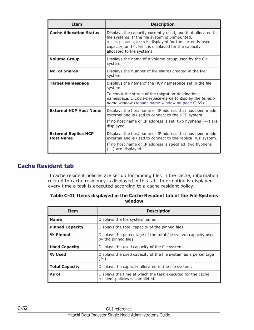
Item Description
Cache Allocation Status Displays the capacity currently used, and that allocated tofile systems. If the file system is unmounted,0.00%(0.00GB)Used is displayed for the currently usedcapacity, and 0.00GB is displayed for the capacityallocated to file systems.
Volume Group Displays the name of a volume group used by the filesystem.
No. of Shares Displays the number of file shares created in the filesystem.
Target Namespace Displays the name of the HCP namespace set in the filesystem.
To check the status of the migration-destinationnamespace, click namespace-name to display the tenant-name window (tenant-name window on page C-69).
External HCP Host Name Displays the host name or IP address that has been madeexternal and is used to connect to the HCP system.
If no host name or IP address is set, two hyphens (--) aredisplayed.
External Replica HCPHost Name
Displays the host name or IP address that has been madeexternal and is used to connect to the replica HCP system.
If no host name or IP address is specified, two hyphens(--) are displayed.
Cache Resident tabIf cache resident policies are set up for pinning files in the cache, informationrelated to cache residency is displayed in this tab. Information is displayedevery time a task is executed according to a cache resident policy.
Table C-41 Items displayed in the Cache Resident tab of the File Systemswindow
Item Description
Name Displays the file system name.
Pinned Capacity Displays the total capacity of the pinned files.
% Pinned Displays the percentage of the total file system capacity usedby the pinned files.
Used Capacity Displays the used capacity of the file system.
% Used Displays the used capacity of the file system as a percentage(%).
Total Capacity Displays the capacity allocated to the file system.
As of Displays the time at which the task executed for the cacheresident policies is completed.
C-52 GUI referenceHitachi Data Ingestor Single Node Administrator's Guide
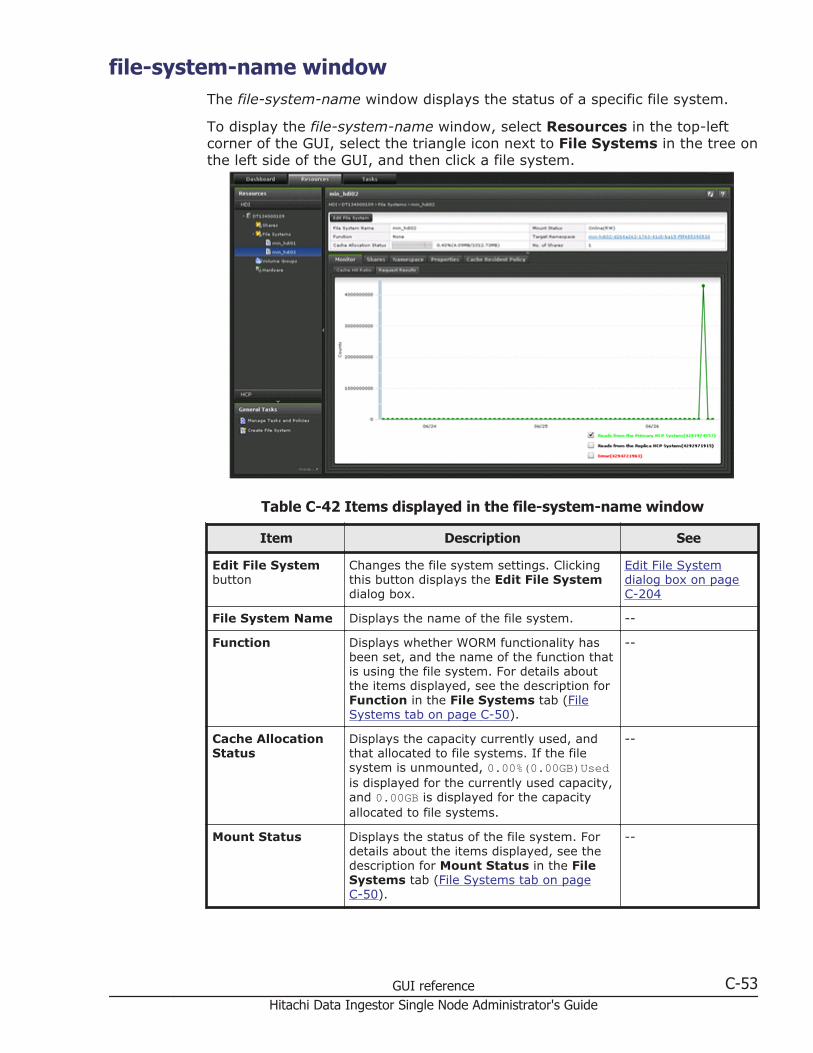
file-system-name windowThe file-system-name window displays the status of a specific file system.
To display the file-system-name window, select Resources in the top-leftcorner of the GUI, select the triangle icon next to File Systems in the tree onthe left side of the GUI, and then click a file system.
Table C-42 Items displayed in the file-system-name window
Item Description See
Edit File Systembutton
Changes the file system settings. Clickingthis button displays the Edit File Systemdialog box.
Edit File Systemdialog box on pageC-204
File System Name Displays the name of the file system. --
Function Displays whether WORM functionality hasbeen set, and the name of the function thatis using the file system. For details aboutthe items displayed, see the description forFunction in the File Systems tab (FileSystems tab on page C-50).
--
Cache AllocationStatus
Displays the capacity currently used, andthat allocated to file systems. If the filesystem is unmounted, 0.00%(0.00GB)Usedis displayed for the currently used capacity,and 0.00GB is displayed for the capacityallocated to file systems.
--
Mount Status Displays the status of the file system. Fordetails about the items displayed, see thedescription for Mount Status in the FileSystems tab (File Systems tab on pageC-50).
--
GUI reference C-53Hitachi Data Ingestor Single Node Administrator's Guide

Item Description See
Target Namespace Displays the name of the HCP namespaceset in the file system.
To check the status of the migration-destination namespace, click namespace-name to display the tenant-name window(tenant-name window on page C-69).
--
No. of Shares Displays the number of file shares createdin the file system.
--
Monitor tab Displays the usage of a client. Monitor tab on pageC-54
Shares tab Displays file share settings. Shares tab on pageC-55
Namespace tab Displays HCP namespace information. Namespace tab onpage C-57
Properties tab Displays the file system settings, such asWORM and version management.
Properties tab onpage C-58
Cache ResidentPolicy tab
Displays the settings for the cache residentpolicies.
Cache ResidentPolicy tab on pageC-60
Monitor tabThe Monitor tab displays the usage of a client.
Table C-43 Items displayed in the Monitor tab of the file-system-namewindow
Item Description
Cache Hit Ratio Displays the percentage of times that a client accesses an HDI systemfile and is able to view that file without recalling data from an HCPsystem.
Note that data is recalled from the HCP system in 1 MB units. If the I/O for a file being temporarily accessed is less than 1 MB, then allsubsequent access to the file might reference the file cached on theHDI system, instead of recalling the file again. This can cause thecache hit ratio to appear higher than it really is.
When importing files from another file server, the cache hit ratiomight appear lower than it really is until the file import processcompletes.
RequestResults
Displays the number of times that data is recalled from an HCPsystem when a client accesses an HDI system file. You can toggle thegraph by selecting the check box in the bottom-right corner of thegraph.
Reads from the Primary HCP System
Displays the number of times data has been recalled from theprimary HCP.
Reads from the Replica HCP System
C-54 GUI referenceHitachi Data Ingestor Single Node Administrator's Guide
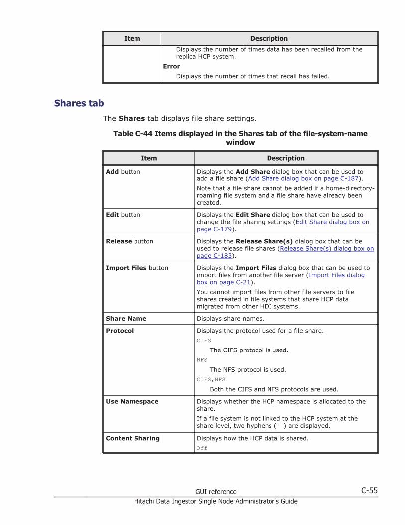
Item Description
Displays the number of times data has been recalled from thereplica HCP system.
Error
Displays the number of times that recall has failed.
Shares tabThe Shares tab displays file share settings.
Table C-44 Items displayed in the Shares tab of the file-system-namewindow
Item Description
Add button Displays the Add Share dialog box that can be used toadd a file share (Add Share dialog box on page C-187).
Note that a file share cannot be added if a home-directory-roaming file system and a file share have already beencreated.
Edit button Displays the Edit Share dialog box that can be used tochange the file sharing settings (Edit Share dialog box onpage C-179).
Release button Displays the Release Share(s) dialog box that can beused to release file shares (Release Share(s) dialog box onpage C-183).
Import Files button Displays the Import Files dialog box that can be used toimport files from another file server (Import Files dialogbox on page C-21).
You cannot import files from other file servers to fileshares created in file systems that share HCP datamigrated from other HDI systems.
Share Name Displays share names.
Protocol Displays the protocol used for a file share.
CIFSThe CIFS protocol is used.
NFSThe NFS protocol is used.
CIFS,NFSBoth the CIFS and NFS protocols are used.
Use Namespace Displays whether the HCP namespace is allocated to theshare.
If a file system is not linked to the HCP system at theshare level, two hyphens (--) are displayed.
Content Sharing Displays how the HCP data is shared.
Off
GUI reference C-55Hitachi Data Ingestor Single Node Administrator's Guide

Item Description
Data in the share is migrated to the HCP system. HCPdata migrated from other HDI systems is not shared.
OnHCP data migrated from other HDI systems is madepublic as read-only.
If a file system is not linked to the HCP system at theshare level, two hyphens (--) are displayed.
CIFS Share Name Displays CIFS share names. Clicking a CIFS share namedisplays the CIFS Protocol Settings dialog box (CIFSProtocol Settings dialog box on page C-177). If the CIFSprotocol is not used, two hyphens (--) are displayed.
Auto Creation of HomeDirectory
Displays whether the function for automatically creating ahome directory is used in the CIFS share. If the CIFSprotocol is not used, two hyphens (--) are displayed.
Export Point Displays the absolute path to the shared directory. Clickthe absolute path when the settings are specified to usethe NFS protocol to display the NFS Protocol Settingsdialog box (NFS Protocol Settings dialog box on pageC-178).
Target Namespace Displays the name of the namespace allocated to theshare.
To check the status of the migration-destinationnamespace, click namespace-name to display the tenant-name window (tenant-name window on page C-69).
If the namespace is not allocated to the share, twohyphens (--) are displayed.
External HCP Host Name Displays the host name or IP address that has been madeexternal and is used to connect to the HCP system.
If no host name or IP address is specified, two hyphens(--) are displayed.
Namespace-accessAccount
Displays the user name of the account used for viewingthe namespace for making HCP data migrated from otherHDI systems public as read-only.
This item is displayed if HCP data is made available asread-only or if data that is to be made available on otherHDI systems is migrated to the HCP system at the sharelevel.
Replica System Name Displays the name of the replica HCP system.
If no replica HCP system information is set, two hyphens(--) are displayed.
External Replica HCPHost Name
Displays the host name or IP address that has been madeexternal and is used to connect to the replica HCP system.
If no host name or IP address is specified, two hyphens(--) are displayed.
C-56 GUI referenceHitachi Data Ingestor Single Node Administrator's Guide
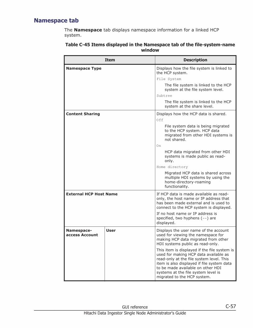
Namespace tabThe Namespace tab displays namespace information for a linked HCPsystem.
Table C-45 Items displayed in the Namespace tab of the file-system-namewindow
Item Description
Namespace Type Displays how the file system is linked tothe HCP system.
File SystemThe file system is linked to the HCPsystem at the file system level.
SubtreeThe file system is linked to the HCPsystem at the share level.
Content Sharing Displays how the HCP data is shared.
OffFile system data is being migratedto the HCP system. HCP datamigrated from other HDI systems isnot shared.
OnHCP data migrated from other HDIsystems is made public as read-only.
Home directoryMigrated HCP data is shared acrossmultiple HDI systems by using thehome-directory-roamingfunctionality.
External HCP Host Name If HCP data is made available as read-only, the host name or IP address thathas been made external and is used toconnect to the HCP system is displayed.
If no host name or IP address isspecified, two hyphens (--) aredisplayed.
Namespace-access Account
User Displays the user name of the accountused for viewing the namespace formaking HCP data migrated from otherHDI systems public as read-only.
This item is displayed if the file system isused for making HCP data available asread-only at the file system level. Thisitem is also displayed if file system datato be made available on other HDIsystems at the file system level ismigrated to the HCP system.
GUI reference C-57Hitachi Data Ingestor Single Node Administrator's Guide
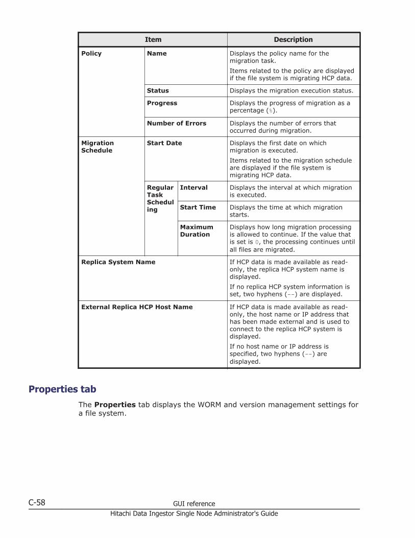
Item Description
Policy Name Displays the policy name for themigration task.
Items related to the policy are displayedif the file system is migrating HCP data.
Status Displays the migration execution status.
Progress Displays the progress of migration as apercentage (%).
Number of Errors Displays the number of errors thatoccurred during migration.
MigrationSchedule
Start Date Displays the first date on whichmigration is executed.
Items related to the migration scheduleare displayed if the file system ismigrating HCP data.
RegularTaskScheduling
Interval Displays the interval at which migrationis executed.
Start Time Displays the time at which migrationstarts.
MaximumDuration
Displays how long migration processingis allowed to continue. If the value thatis set is 0, the processing continues untilall files are migrated.
Replica System Name If HCP data is made available as read-only, the replica HCP system name isdisplayed.
If no replica HCP system information isset, two hyphens (--) are displayed.
External Replica HCP Host Name If HCP data is made available as read-only, the host name or IP address thathas been made external and is used toconnect to the replica HCP system isdisplayed.
If no host name or IP address isspecified, two hyphens (--) aredisplayed.
Properties tabThe Properties tab displays the WORM and version management settings fora file system.
C-58 GUI referenceHitachi Data Ingestor Single Node Administrator's Guide
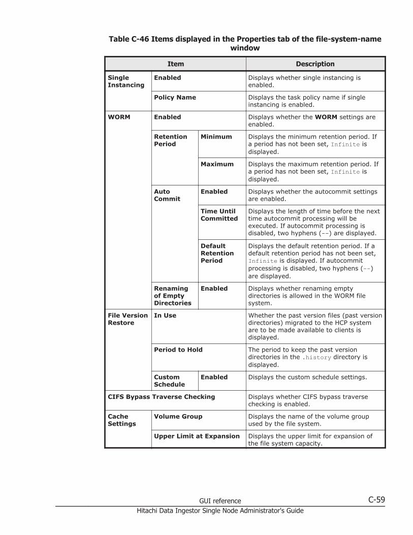
Table C-46 Items displayed in the Properties tab of the file-system-namewindow
Item Description
SingleInstancing
Enabled Displays whether single instancing isenabled.
Policy Name Displays the task policy name if singleinstancing is enabled.
WORM Enabled Displays whether the WORM settings areenabled.
RetentionPeriod
Minimum Displays the minimum retention period. Ifa period has not been set, Infinite isdisplayed.
Maximum Displays the maximum retention period. Ifa period has not been set, Infinite isdisplayed.
AutoCommit
Enabled Displays whether the autocommit settingsare enabled.
Time UntilCommitted
Displays the length of time before the nexttime autocommit processing will beexecuted. If autocommit processing isdisabled, two hyphens (--) are displayed.
DefaultRetentionPeriod
Displays the default retention period. If adefault retention period has not been set,Infinite is displayed. If autocommitprocessing is disabled, two hyphens (--)are displayed.
Renamingof EmptyDirectories
Enabled Displays whether renaming emptydirectories is allowed in the WORM filesystem.
File VersionRestore
In Use Whether the past version files (past versiondirectories) migrated to the HCP systemare to be made available to clients isdisplayed.
Period to Hold The period to keep the past versiondirectories in the .history directory isdisplayed.
CustomSchedule
Enabled Displays the custom schedule settings.
CIFS Bypass Traverse Checking Displays whether CIFS bypass traversechecking is enabled.
CacheSettings
Volume Group Displays the name of the volume groupused by the file system.
Upper Limit at Expansion Displays the upper limit for expansion ofthe file system capacity.
GUI reference C-59Hitachi Data Ingestor Single Node Administrator's Guide

Item Description
If the initial capacity of a created filesystem is equal to or less than 32 GB, themaximum capacity after expansion will beless than the displayed value. For detailsabout the initial capacity of a created filesystem and the maximum capacity afterexpansion, see the CLI Administrator'sGuide.
Cache Resident Policy tabThe Cache Resident Policy tab displays policy information when cacheresident policies are set up to prevent files from turning into stub files.
Table C-47 Items displayed in the Cache Resident Policy tab of the file-system-name window
Item Description
Total Pinned Capacity Displays the total capacity of pinned files.
Add button Click to add a policy. Clicking this button displays the AddCache Resident Policy dialog box (Add Cache ResidentPolicy dialog box on page C-212).
Edit button Click to edit the conditions for a policy. Clicking thisbutton displays the Edit Cache Resident Policy dialogbox (Edit Cache Resident Policy dialog box on pageC-213).
Delete button Click to delete a policy. Clicking this button displays theDelete Cache Resident Policy dialog box (Delete CacheResident Policy dialog box on page C-214).
Download List of PinnedFiles button
Click to download a text file containing a list of pinnedfiles.
Policy Name Displays the policy name.
Directory Displays the directory name.
File Types Displays file type conditions.
File Size Range Min Displays minimum file size conditions.
Max Displays maximum file size conditions.
Comments Displays comments about the policy.
Volume Groups windowThe Volume Groups window displays the status of volume groups.
To display the Volume Groups window, select Resources in the top-leftcorner of the GUI, select the triangle icon next to host-name in the tree onthe left side of the GUI, and then click Volume Groups.
C-60 GUI referenceHitachi Data Ingestor Single Node Administrator's Guide
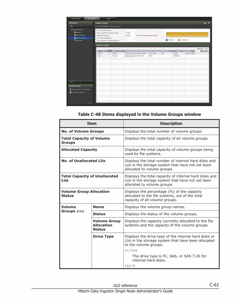
Table C-48 Items displayed in the Volume Groups window
Item Description
No. of Volume Groups Displays the total number of volume groups.
Total Capacity of VolumeGroups
Displays the total capacity of all volume groups.
Allocated Capacity Displays the total capacity of volume groups beingused by file systems.
No. of Unallocated LUs Displays the total number of internal hard disks andLUs in the storage system that have not yet beenallocated to volume groups.
Total Capacity of UnallocatedLUs
Displays the total capacity of internal hard disks andLUs in the storage system that have not yet beenallocated to volume groups.
Volume Group AllocationStatus
Displays the percentage (%) of the capacityallocated to the file systems, out of the totalcapacity of all volume groups.
VolumeGroups area
Name Displays the volume group names.
Status Displays the status of the volume groups.
Volume GroupAllocationStatus
Displays the capacity currently allocated to the filesystems and the capacity of the volume groups.
Drive Type Displays the drive type of the internal hard disks orLUs in the storage system that have been allocatedto the volume groups.
FC/SASThe drive type is FC, SAS, or SAS 7.2K forinternal hard disks.
SAS7K
GUI reference C-61Hitachi Data Ingestor Single Node Administrator's Guide

Item Description
The drive type is SAS 7.2K.
SATAThe drive type is SATA.
SSDThe drive type is SSD.
MixedMultiple drive types coexist.
Also, -- is displayed if the LU is a virtual LU thatuses Dynamic Tiering.
Pool If virtual LUs for Dynamic Provisioning have beenallocated to the volume group, the number of thepool to which the virtual LUs belong is displayed. Ifvirtual LUs belong to multiple pools, Mixed isdisplayed.
If no virtual LUs are allocated, -- is displayed.
Model Displays the model of the storage system thatcontains the LUs allocated to the volume groups. Forinternal hard disks, INTERNAL is displayed.
Serial Number Displays the serial number of the storage systemthat contains the LUs allocated to the volumegroups. For internal hard disks, -- is displayed.
Hardware windowThe Hardware window displays the hardware and network statuses.
To display the Hardware window, select Resources in the top-left corner ofthe GUI, select the triangle icon next to a host name in the tree on the leftside of the GUI, and then click Hardware.
C-62 GUI referenceHitachi Data Ingestor Single Node Administrator's Guide
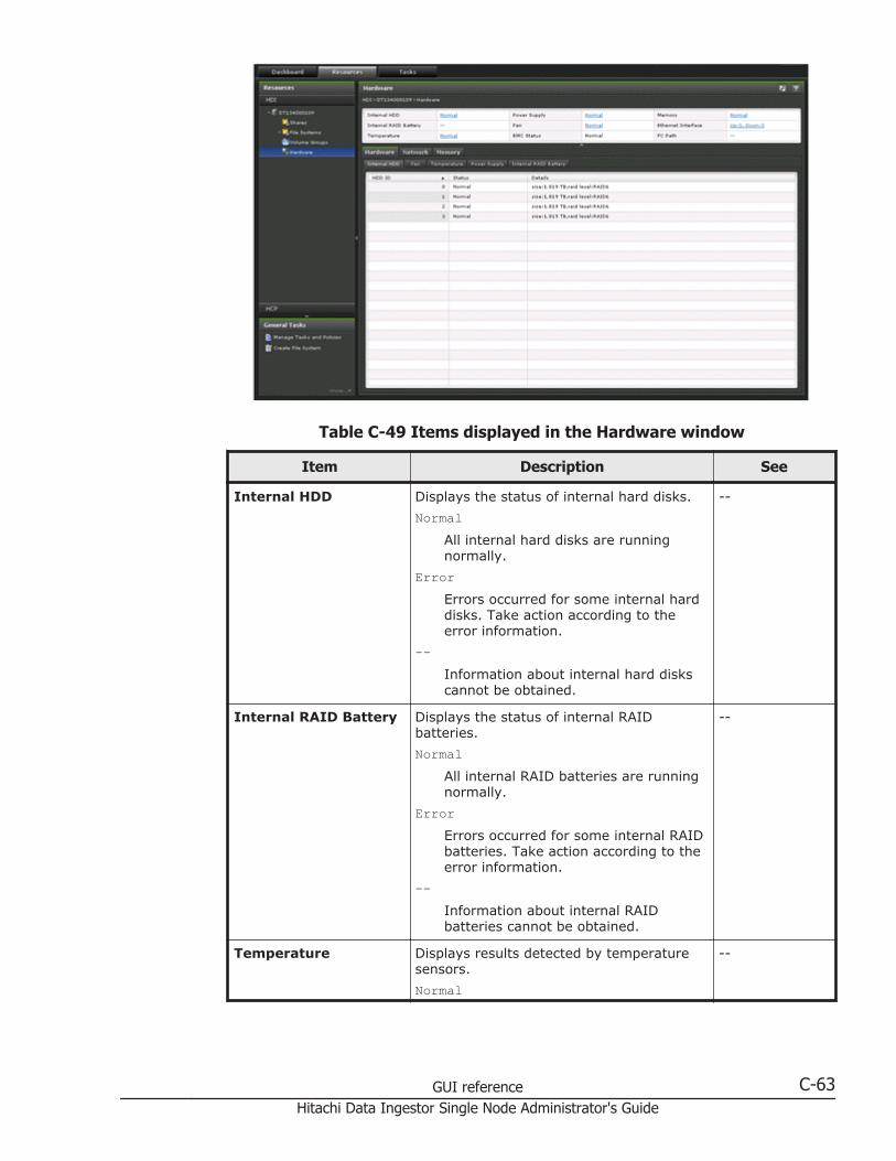
Table C-49 Items displayed in the Hardware window
Item Description See
Internal HDD Displays the status of internal hard disks.
NormalAll internal hard disks are runningnormally.
ErrorErrors occurred for some internal harddisks. Take action according to theerror information.
--Information about internal hard diskscannot be obtained.
--
Internal RAID Battery Displays the status of internal RAIDbatteries.
NormalAll internal RAID batteries are runningnormally.
ErrorErrors occurred for some internal RAIDbatteries. Take action according to theerror information.
--Information about internal RAIDbatteries cannot be obtained.
--
Temperature Displays results detected by temperaturesensors.
Normal
--
GUI reference C-63Hitachi Data Ingestor Single Node Administrator's Guide

Item Description See
All temperature sensors are detectingnormal temperatures.
ErrorSome temperature sensors detectedabnormal temperatures. Take actionaccording to the error information.
--Information about temperature sensorscannot be obtained.
Power Supply Displays power unit statuses.
NormalAll power units are running normally.
ErrorErrors occurred for some power units.Take action according to the errorinformation.
--Information about power units cannotbe obtained.
--
Fan Displays the fan status.
NormalAll fans are running normally.
ErrorErrors occurred for some fans. Takeaction according to the errorinformation.
--Information about fans cannot beobtained.
--
BMC Status Displays BMC statuses.
NormalAll BMCs are running normally.
ErrorErrors occurred for some BMCs. Takeaction according to the errorinformation.
--Information about BMCs could not beobtained.
--
Memory Displays the memory status.
NormalAll memory is running normally.
Error
--
C-64 GUI referenceHitachi Data Ingestor Single Node Administrator's Guide

Item Description See
Errors occurred for some memory.Take action according to the errorinformation.
--Information about memory cannot beobtained.
Ethernet Interface Displays the status of Ethernet interfaces(ethn, mng0, and pm0).
The display format is as follows:Up: number-of-ports-with-Up-link-status, Down: number-of-ports-with-Down-link-status
--
FC Path Displays the FC path status if a storagesystem is to be connected. If no storagesystems will be connected to, two hyphens(--) are displayed.
--
Hardware tab Displays the hardware status for a node. Hardware tabon page C-65
Network tab Displays the network status. Network tab onpage C-67
Memory tab Displays the memory information. Memory tab onpage C-69
Hardware tabThe Hardware tab displays the hardware status for a node.
Table C-50 Items displayed in the Hardware tab of the Hardware window
Item Description
Internal HDD tab Displays detailed information about the status of the internal harddisk.
HDD ID
Displays the ID of the internal hard disk.
Status
Displays the status of the internal hard disk.
Normal: The internal hard disk is running normally.
Error: An error has occurred for the internal hard disk.
Rebuild: The internal hard disk is currently being formattedor RAID is being constructed.
Not supported: The program that collects information hasnot been installed.
Removed: The internal hard disk was removed from the RAIDgroup.
Nodevice: The internal hard disk was removed from thenode.
GUI reference C-65Hitachi Data Ingestor Single Node Administrator's Guide

Item Description
Setup: The internal hard disk installed on the node is notincluded in the RAID group.
--: Information about the internal hard disk cannot beobtained.
Details
Displays information about the internal hard disk.
Fan tab Displays detailed information about the status of the fan.
Fan ID
Displays the fan ID.
Status
Displays the fan status.
Normal: The fan is running normally.
Error: An error has occurred for the fan.
--: Information about the fan cannot be obtained.
Details
Displays detailed information about the fan.
Temperature tab Displays detailed information about the status of the temperaturesensor.
Sensor ID
Displays the ID of the temperature sensor.
Status
Displays the status of the temperature sensor.
Normal: The temperature sensor is running normally.
Error: An error has occurred for the temperature sensor.
--: Information about the temperature sensor cannot beobtained.
Details
Displays detailed information about the temperature sensor.
Power Supply tab Displays detailed information about the status of the power unit.
Power Supply ID
Displays the ID of the power unit.
Status
Displays the status of the power unit.
Normal: The power unit is running normally.
Error: An error occurred for the power unit.
Not installed: No power units are installed.
--: Information about the power unit cannot be obtained.
Details
Displays detailed information about the power unit.
Internal RAIDBattery tab
Displays detailed information about the internal RAID battery.
Battery ID
Displays the ID of the internal RAID battery.
C-66 GUI referenceHitachi Data Ingestor Single Node Administrator's Guide
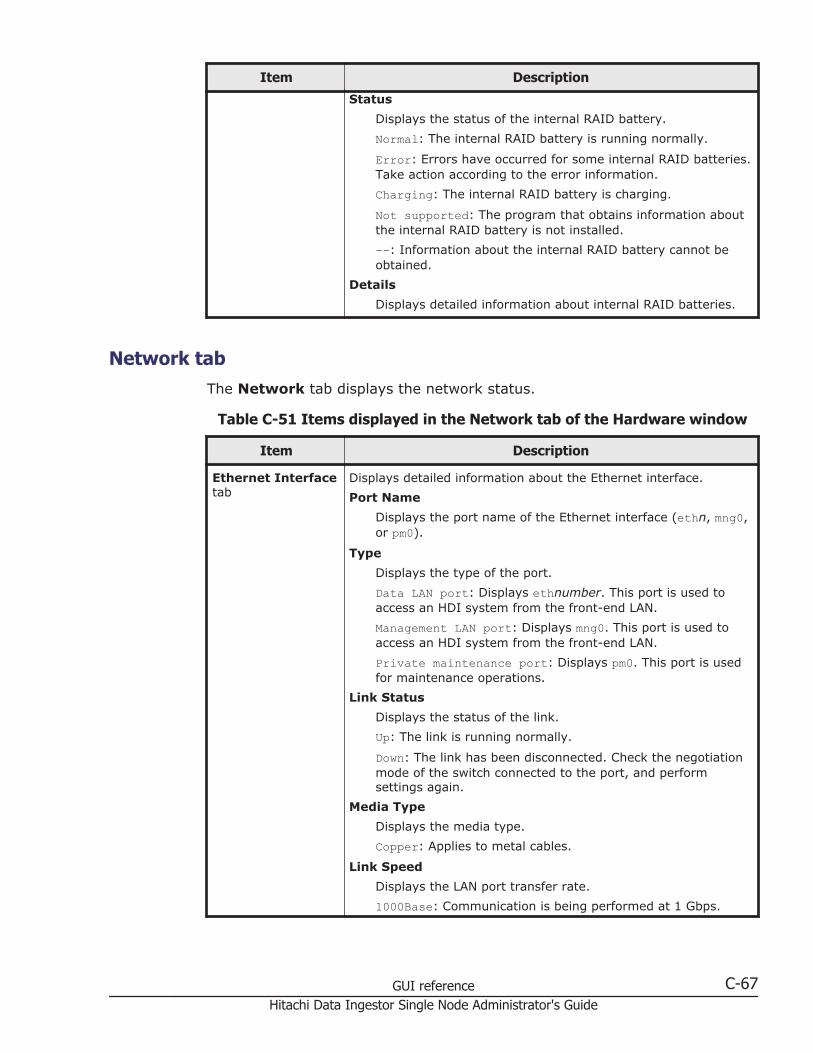
Item Description
Status
Displays the status of the internal RAID battery.
Normal: The internal RAID battery is running normally.
Error: Errors have occurred for some internal RAID batteries.Take action according to the error information.
Charging: The internal RAID battery is charging.
Not supported: The program that obtains information aboutthe internal RAID battery is not installed.
--: Information about the internal RAID battery cannot beobtained.
Details
Displays detailed information about internal RAID batteries.
Network tabThe Network tab displays the network status.
Table C-51 Items displayed in the Network tab of the Hardware window
Item Description
Ethernet Interfacetab
Displays detailed information about the Ethernet interface.
Port Name
Displays the port name of the Ethernet interface (ethn, mng0,or pm0).
Type
Displays the type of the port.
Data LAN port: Displays ethnumber. This port is used toaccess an HDI system from the front-end LAN.
Management LAN port: Displays mng0. This port is used toaccess an HDI system from the front-end LAN.
Private maintenance port: Displays pm0. This port is usedfor maintenance operations.
Link Status
Displays the status of the link.
Up: The link is running normally.
Down: The link has been disconnected. Check the negotiationmode of the switch connected to the port, and performsettings again.
Media Type
Displays the media type.
Copper: Applies to metal cables.
Link Speed
Displays the LAN port transfer rate.
1000Base: Communication is being performed at 1 Gbps.
GUI reference C-67Hitachi Data Ingestor Single Node Administrator's Guide
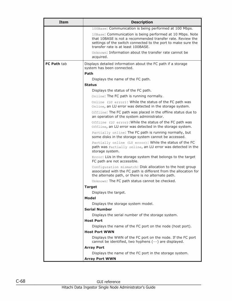
Item Description
100Base: Communication is being performed at 100 Mbps.
10Base: Communication is being performed at 10 Mbps. Notethat 10BASE is not a recommended transfer rate. Review thesettings of the switch connected to the port to make sure thetransfer rate is at least 100BASE.
Unknown: Information about the transfer rate cannot beacquired.
FC Path tab Displays detailed information about the FC path if a storagesystem has been connected.
Path
Displays the name of the FC path.
Status
Displays the status of the FC path.
Online: The FC path is running normally.
Online (LU error): While the status of the FC path wasOnline, an LU error was detected in the storage system.
Offline: The FC path was placed in the offline status due toan operation of the system administrator.
Offline (LU error):While the status of the FC path wasOffline, an LU error was detected in the storage system.
Partially online: The FC path is running normally, butsome disks in the storage system cannot be accessed.
Partially online (LU error): While the status of the FCpath was Partially online, an LU error was detected in thestorage system.
Error: LUs in the storage system that belongs to the targetFC path are not accessible.
Configuration mismatch: Disk allocation to the host groupassociated with the FC path is different from the allocation forthe alternate path, or there is no alternate path.
Unknown: The FC path status cannot be checked.
Target
Displays the target.
Model
Displays the storage system model.
Serial Number
Displays the serial number of the storage system.
Host Port
Displays the name of the FC port on the node (host port).
Host Port WWN
Displays the WWN of the FC port on the node. If the FC portcannot be identified, two hyphens (--) are displayed.
Array Port
Displays the name of the FC port in the storage system.
Array Port WWN
C-68 GUI referenceHitachi Data Ingestor Single Node Administrator's Guide

Item Description
Displays the WWN of the FC port in the storage system. If anerror occurred in the FC path, two hyphens (--) aredisplayed.
Memory tabThe Memory tab displays the memory information.
Table C-52 Items displayed in the Memory tab of the Hardware window
Item Description
Memory Total tab Displays details about the memory size.
Size
Displays the memory size in the following format:
size:amount-of-memory-recognized-by-system
Details tab Displays the detailed memory status information.
Memory ID
Displays the ID of a memory slot.
Status
Displays the memory status.
Installed: The memory is installed.
Not installed: No memory is installed.
--: The memory information cannot be obtained.
Details
The detailed memory information is displayed.
tenant-name windowThe tenant-name window displays tenant information for a linked HCPsystem.
To display the tenant-name window, select Resources in the top-left cornerof the GUI, and then click HCP in the tree on the left side of the GUI.
GUI reference C-69Hitachi Data Ingestor Single Node Administrator's Guide

Table C-53 Items displayed in the tenant-name window
Item Description See
Name Displays the tenant name. --
System Name Displays the HCP system name. --
Quota Displays the maximum capacity that canbe used by the linked tenant.
--
Storage Capacity Used Displays the current capacity used by thelinked tenant and the percentage of themaximum capacity that the tenant canuse.
--
Namespaces tab Displays a list of migration-destinationnamespaces.
Namespacestab on pageC-70
Properties tab Displays the tenant settings. Properties tabon page C-71
Namespaces tabThe Namespaces tab displays the used capacity of a namespace and thename of a migration-source file system.
Table C-54 Items displayed in the Namespaces tab of the tenant-namewindow
Item Description
Name The name of the namespace.
C-70 GUI referenceHitachi Data Ingestor Single Node Administrator's Guide
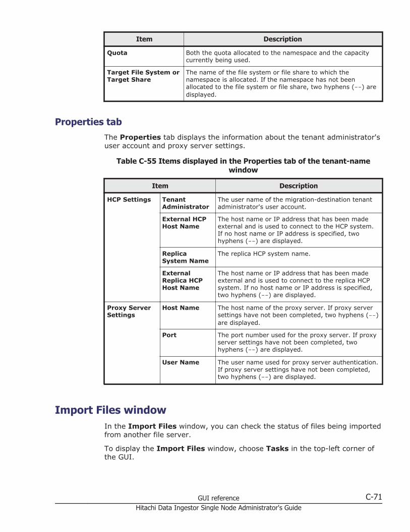
Item Description
Quota Both the quota allocated to the namespace and the capacitycurrently being used.
Target File System orTarget Share
The name of the file system or file share to which thenamespace is allocated. If the namespace has not beenallocated to the file system or file share, two hyphens (--) aredisplayed.
Properties tabThe Properties tab displays the information about the tenant administrator'suser account and proxy server settings.
Table C-55 Items displayed in the Properties tab of the tenant-namewindow
Item Description
HCP Settings TenantAdministrator
The user name of the migration-destination tenantadministrator's user account.
External HCPHost Name
The host name or IP address that has been madeexternal and is used to connect to the HCP system.If no host name or IP address is specified, twohyphens (--) are displayed.
ReplicaSystem Name
The replica HCP system name.
ExternalReplica HCPHost Name
The host name or IP address that has been madeexternal and is used to connect to the replica HCPsystem. If no host name or IP address is specified,two hyphens (--) are displayed.
Proxy ServerSettings
Host Name The host name of the proxy server. If proxy serversettings have not been completed, two hyphens (--)are displayed.
Port The port number used for the proxy server. If proxyserver settings have not been completed, twohyphens (--) are displayed.
User Name The user name used for proxy server authentication.If proxy server settings have not been completed,two hyphens (--) are displayed.
Import Files windowIn the Import Files window, you can check the status of files being importedfrom another file server.
To display the Import Files window, choose Tasks in the top-left corner ofthe GUI.
GUI reference C-71Hitachi Data Ingestor Single Node Administrator's Guide

Table C-56 Items displayed in the Import Files window
Item Description
Start Importbutton
Starts the importing of files. This button becomes active afterverification of files finishes.
Clicking this button displays a confirmation dialog box (Table C-57Items displayed in the confirmation dialog box for task operationson page C-73).
Cancel Importbutton
Stops the importing of files.
Clicking this button displays a confirmation dialog box (Table C-57Items displayed in the confirmation dialog box for task operationson page C-73).
Cancel Scan button Stops the verification of files.
Clicking this button displays a confirmation dialog box (Table C-57Items displayed in the confirmation dialog box for task operationson page C-73).
Show Detail button Checks the details about the task.
Clicking this button displays the Import Files dialog box (ImportFiles dialog box on page C-21).
More ActionsClick and perform the necessary operation.
Change to On-Demand Import
Changes the import method to on-demand importing. If youclick this button to change the import method, only thesource files that are requested by a client are imported whenthe client accesses the files.
Clone Task
Defines a task that has the same settings as the selectedtask.
Delete Task
C-72 GUI referenceHitachi Data Ingestor Single Node Administrator's Guide
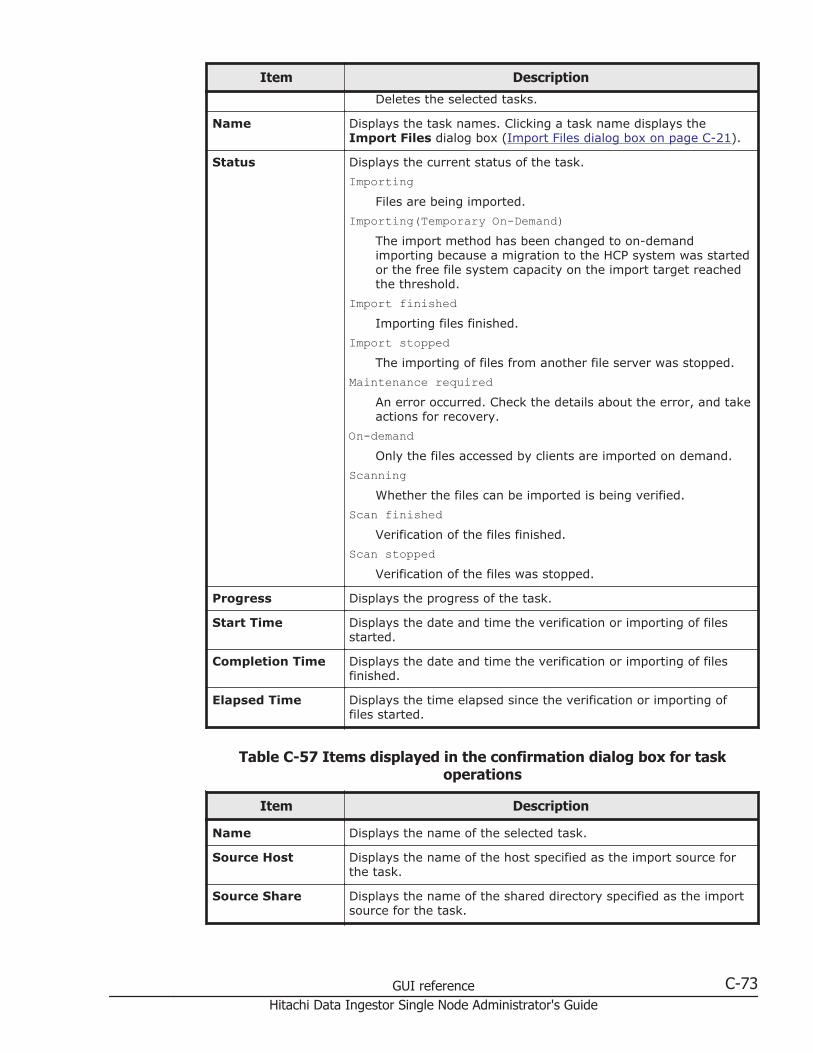
Item Description
Deletes the selected tasks.
Name Displays the task names. Clicking a task name displays theImport Files dialog box (Import Files dialog box on page C-21).
Status Displays the current status of the task.
ImportingFiles are being imported.
Importing(Temporary On-Demand)The import method has been changed to on-demandimporting because a migration to the HCP system was startedor the free file system capacity on the import target reachedthe threshold.
Import finishedImporting files finished.
Import stoppedThe importing of files from another file server was stopped.
Maintenance requiredAn error occurred. Check the details about the error, and takeactions for recovery.
On-demandOnly the files accessed by clients are imported on demand.
ScanningWhether the files can be imported is being verified.
Scan finishedVerification of the files finished.
Scan stoppedVerification of the files was stopped.
Progress Displays the progress of the task.
Start Time Displays the date and time the verification or importing of filesstarted.
Completion Time Displays the date and time the verification or importing of filesfinished.
Elapsed Time Displays the time elapsed since the verification or importing offiles started.
Table C-57 Items displayed in the confirmation dialog box for taskoperations
Item Description
Name Displays the name of the selected task.
Source Host Displays the name of the host specified as the import source forthe task.
Source Share Displays the name of the shared directory specified as the importsource for the task.
GUI reference C-73Hitachi Data Ingestor Single Node Administrator's Guide

Item Description
Target Host Displays the HDI node specified as the import target of files forthe task.
Target Share Displays the name of the shared directory of the HDI specified asthe import target of files for the task.
Apply button Execute the operation.
Restart Node dialog boxYou can restart a node.
To display the Restart Node dialog box, click the Restart Node button inthe host-name window.
Note: If you are using encryption, when you save system settings to the HCPsystem, confirm that the HCP system is running normally and that the HDIand HCP systems can communicate normally before restarting the node.
Table C-58 Items displayed in the Restart Node dialog box
Item Description
NodeInformation
Host Name The name of the host on the node
Node status The node status.
OnlineThe node is operating normally.
Online PendingThe node is being started.
OfflineThe node is not running.
Offline PendingThe node is being stopped.
Partial OnlineSome services are not running.
ErrorAn error has occurred. See the errorinformation, and take appropriate action.
IP Address(mng0)
The IP address
Yes, I have read the abovewarning. check box
Select this check box if you want to restart the node.
Apply button Restarts the node. The Yes, I have read theabove warning. check box must be selected beforeyou click this button.
C-74 GUI referenceHitachi Data Ingestor Single Node Administrator's Guide

System Software Installation dialog boxYou can update the software running on the node. You can also checkwhether the latest software has been installed.
To display the System Software Installation dialog box, click SoftwareUpdate in the Settings area of the host-name window.
Table C-59 Items displayed on the System Software Installation dialogbox
Item Description
Product name Displays the name of the installed product.
Current version Displays the version of the software that is currentlyinstalled.
Backup Configurationbutton
Saves the system configuration information beforeinstalling the software. Click this button to display theBackup Configuration dialog box (Backup Configurationdialog box on page C-87).
This button appears when the HCP Anywhere is not linked.
AvailableVersions
SystemVersion
Displays a list of the software versions that can beinstalled.
I want to update thesystem software. or Yes,I backed up the systemsettings and wish toupdate the systemsoftware. check box
Checks information before installing the software.
Install button Installs the software. Select the software version that youwant to install, select I want to update the systemsoftware. or Yes, I backed up the system settingsand wish to update the system software., and thenclick this button.
Local Users dialog boxYou can manage information about the users who can access a file system.
To display the Local Users dialog box, click Local Users in the Settingsarea of the host-name window.
List of Users / Groups pageYou can view the information about the users registered in an HDI systemand the groups containing users.
The List of Users / Groups page appears first when the Local Users dialogbox is displayed.
GUI reference C-75Hitachi Data Ingestor Single Node Administrator's Guide
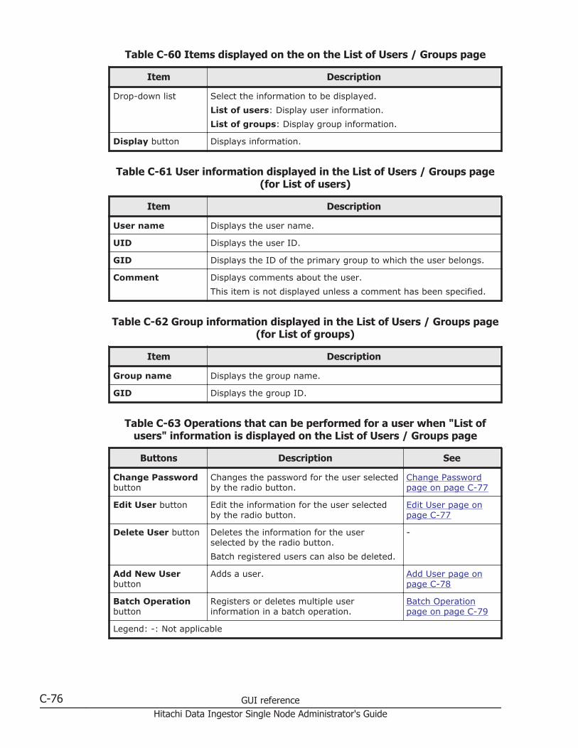
Table C-60 Items displayed on the on the List of Users / Groups page
Item Description
Drop-down list Select the information to be displayed.
List of users: Display user information.
List of groups: Display group information.
Display button Displays information.
Table C-61 User information displayed in the List of Users / Groups page(for List of users)
Item Description
User name Displays the user name.
UID Displays the user ID.
GID Displays the ID of the primary group to which the user belongs.
Comment Displays comments about the user.
This item is not displayed unless a comment has been specified.
Table C-62 Group information displayed in the List of Users / Groups page(for List of groups)
Item Description
Group name Displays the group name.
GID Displays the group ID.
Table C-63 Operations that can be performed for a user when "List ofusers" information is displayed on the List of Users / Groups page
Buttons Description See
Change Passwordbutton
Changes the password for the user selectedby the radio button.
Change Passwordpage on page C-77
Edit User button Edit the information for the user selectedby the radio button.
Edit User page onpage C-77
Delete User button Deletes the information for the userselected by the radio button.
Batch registered users can also be deleted.
-
Add New Userbutton
Adds a user. Add User page onpage C-78
Batch Operationbutton
Registers or deletes multiple userinformation in a batch operation.
Batch Operationpage on page C-79
Legend: -: Not applicable
C-76 GUI referenceHitachi Data Ingestor Single Node Administrator's Guide

Table C-64 Operations that can be performed for a user when "List ofgroups" information is displayed on the List of Users / Groups page
Buttons Description See
Edit Group button Edits the information for the group selectedby the radio button.
Edit Group page onpage C-85
Delete Groupbutton
Deletes the information for the groupselected by the radio button.
-
Add New Groupbutton
Adds a group. Add Group page onpage C-86
Legend: -: Not applicable
Change Password pageYou can change the password of a user.
To display the Change Password page, select List of users from the drop-down list on the List of Users / Groups page, click the Display button,select the user, and then click the Change Password button.
Table C-65 Items displayed on the Change Password page
Item Description
User name Displays the user name whose password you want tochange.
New password Enter the new password.
Re-enter new password Re-enter the password you set in New password.
Edit User pageYou can edit user information.
To display the Edit User page, select List of users from the drop-down liston the List of Users / Groups page, click the Display button, select theuser, and then click the Edit User button.
Note: Items whose information is not changed retain their current settings.
Table C-66 Items displayed on the Edit User page
Item Description
User name Displays the user name.
UID Displays the user ID.
GID Change the ID of the primary group to which the user belongs.
GUI reference C-77Hitachi Data Ingestor Single Node Administrator's Guide
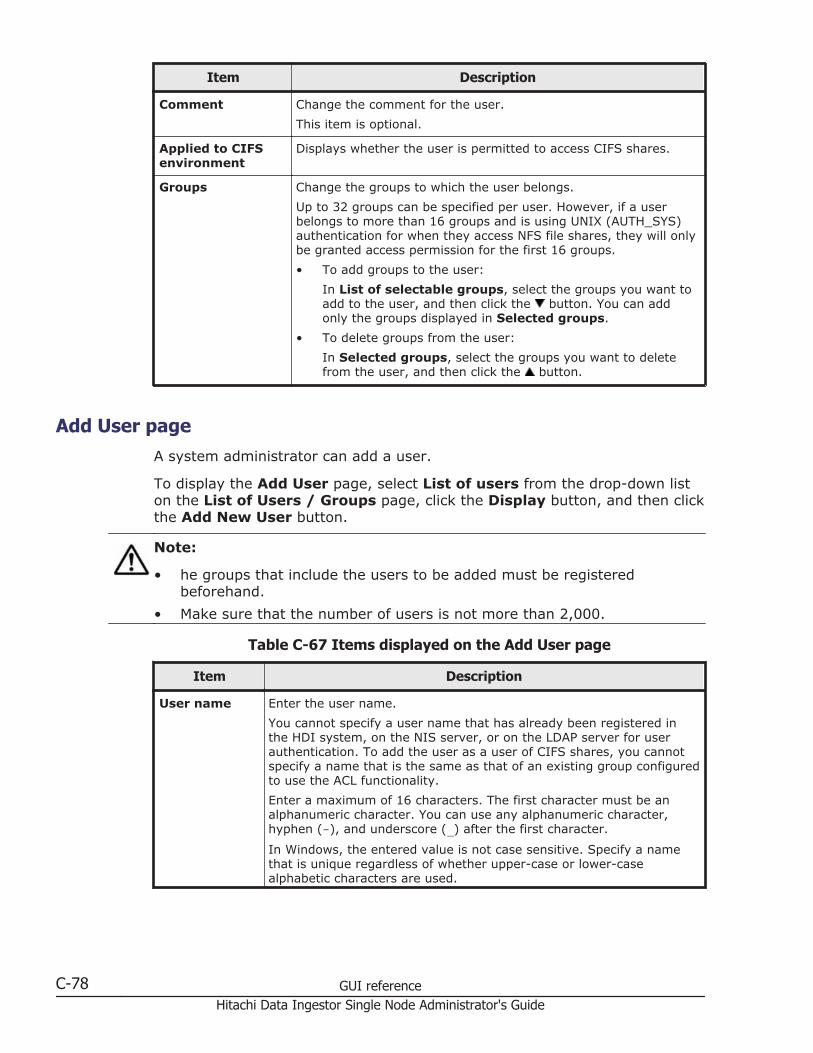
Item Description
Comment Change the comment for the user.
This item is optional.
Applied to CIFSenvironment
Displays whether the user is permitted to access CIFS shares.
Groups Change the groups to which the user belongs.
Up to 32 groups can be specified per user. However, if a userbelongs to more than 16 groups and is using UNIX (AUTH_SYS)authentication for when they access NFS file shares, they will onlybe granted access permission for the first 16 groups.
• To add groups to the user:
In List of selectable groups, select the groups you want toadd to the user, and then click the button. You can addonly the groups displayed in Selected groups.
• To delete groups from the user:
In Selected groups, select the groups you want to deletefrom the user, and then click the button.
Add User pageA system administrator can add a user.
To display the Add User page, select List of users from the drop-down liston the List of Users / Groups page, click the Display button, and then clickthe Add New User button.
Note:
• he groups that include the users to be added must be registeredbeforehand.
• Make sure that the number of users is not more than 2,000.
Table C-67 Items displayed on the Add User page
Item Description
User name Enter the user name.
You cannot specify a user name that has already been registered inthe HDI system, on the NIS server, or on the LDAP server for userauthentication. To add the user as a user of CIFS shares, you cannotspecify a name that is the same as that of an existing group configuredto use the ACL functionality.
Enter a maximum of 16 characters. The first character must be analphanumeric character. You can use any alphanumeric character,hyphen (-), and underscore (_) after the first character.
In Windows, the entered value is not case sensitive. Specify a namethat is unique regardless of whether upper-case or lower-casealphabetic characters are used.
C-78 GUI referenceHitachi Data Ingestor Single Node Administrator's Guide

Item Description
Also, you cannot specify the user name already shown in Table E-2 Listof reserved words for the user name on page E-2 because the username is reserved by the OS.
UID Enter the user ID.
Specify a value from 200 to 2147483147. You cannot specify 65534 orthe user ID that has already been registered in the HDI system, on theNIS server, or on the LDAP server for user authentication. In addition,when user mapping is being used, you cannot specify the user IDswithin the ID range set by user mapping.
GID Specify the ID of the primary group to which the user belongs.
Password Enter the user password. Specify from 6 to 20 (inclusive) characters.You can specify alphanumeric characters and the following symbols:
! " # $ % & ' ( ) * + , - . / : ; < = > ? @ [ \ ] ^ _ `{ | } ~
Re-enterpassword
Re-enter the password you set in Password.
Comment Enter a comment for the user. Use a maximum of 32 characters. Youcan specify alphanumeric characters and the following symbols:
# % & ' ( ) * + - . / ; < > ? @ [ ] ^ _ { | } ~You can also specify spaces, but not at the beginning or end of thecharacter string.
This item is optional.
When the user uses CIFS shares, this comment is used for displayingACLs.
Apply to CIFSenvironment
Select this check box when you want to add the user as a user of CIFSshares.
Groups Specify groups to which the user belongs.
Select, in List of selectable groups, the groups you want to add tothe user, and then click the button. You can add only groups thatare displayed in Selected groups.
Up to 32 groups can be specified per user. However, if a user belongsto more than 16 groups and is using UNIX (AUTH_SYS) authenticationfor when they access NFS file shares, they will only be granted accesspermission for the first 16 groups.
To delete groups from a user, select the user in Selected users, andthen click the button.
Batch Operation pageUse a CSV file containing user information to register or delete informationabout multiple users in a batch operation.
Note:
• Prepare the CSV file containing user information in advance. For detailsabout the CSV file format, see CSV file format on page C-80.
GUI reference C-79Hitachi Data Ingestor Single Node Administrator's Guide
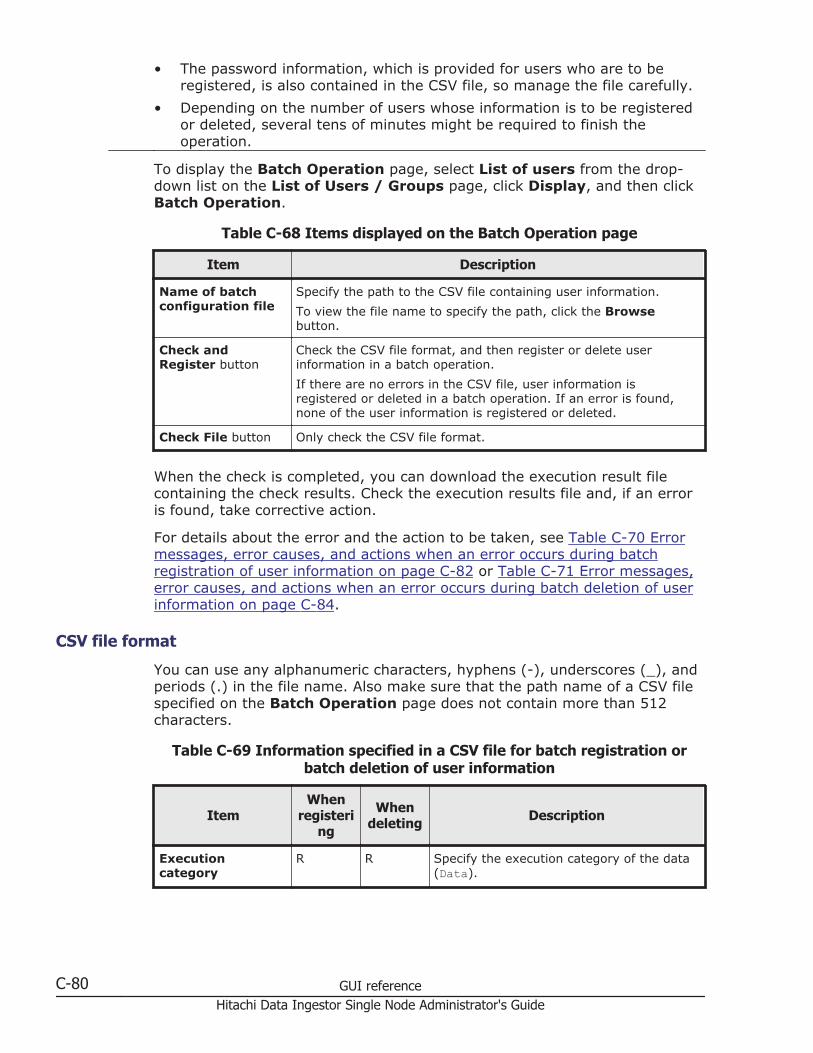
• The password information, which is provided for users who are to beregistered, is also contained in the CSV file, so manage the file carefully.
• Depending on the number of users whose information is to be registeredor deleted, several tens of minutes might be required to finish theoperation.
To display the Batch Operation page, select List of users from the drop-down list on the List of Users / Groups page, click Display, and then clickBatch Operation.
Table C-68 Items displayed on the Batch Operation page
Item Description
Name of batchconfiguration file
Specify the path to the CSV file containing user information.
To view the file name to specify the path, click the Browsebutton.
Check andRegister button
Check the CSV file format, and then register or delete userinformation in a batch operation.
If there are no errors in the CSV file, user information isregistered or deleted in a batch operation. If an error is found,none of the user information is registered or deleted.
Check File button Only check the CSV file format.
When the check is completed, you can download the execution result filecontaining the check results. Check the execution results file and, if an erroris found, take corrective action.
For details about the error and the action to be taken, see Table C-70 Errormessages, error causes, and actions when an error occurs during batchregistration of user information on page C-82 or Table C-71 Error messages,error causes, and actions when an error occurs during batch deletion of userinformation on page C-84.
CSV file format
You can use any alphanumeric characters, hyphens (-), underscores (_), andperiods (.) in the file name. Also make sure that the path name of a CSV filespecified on the Batch Operation page does not contain more than 512characters.
Table C-69 Information specified in a CSV file for batch registration orbatch deletion of user information
ItemWhen
registering
Whendeleting Description
Executioncategory
R R Specify the execution category of the data(Data).
C-80 GUI referenceHitachi Data Ingestor Single Node Administrator's Guide

ItemWhen
registering
Whendeleting Description
Data classification R R The processing classification of the data.Note that UA01 and UD01 cannot existwithin the same file.
UA01Batch-register the data.
UD01Batch-delete the data.
Data registrationdestination
R R To register user information:
Specify where the user information is to beregistered or reflected.
1Register in the HDI system.
3Register the users in the HDI systemas users who access CIFS shares.
To delete user information:
Use the information directly below thistable to create a CSV file for deleting userinformation.
User name R R Specify the user name.
The values that can be specified are thesame as those that can be specified inUser name, in the Add User page.
UID R N/R Specify the user ID.
The values that can be specified are thesame as those that can be specified in UID,in the Add User page.
GID R N/R Specify the ID of the primary group towhich the user belongs.
Password R N/R Specify the user password.
The values that can be specified are thesame as those that can be specified inPassword, in the Add User page.
Comment I N/R Specify a comment for the user.
The values that can be specified are thesame as those that can be specified inComment, in the Add User page.
Groups I N/R Use a group name or group ID to specifythe other groups to which the user belongs.
Use commas (,) to delimit multiple groupnames or group IDs, and enclose the entirestring with double quotation marks (").
Legend: R: Required. I: If necessary. N/R: Not required.
GUI reference C-81Hitachi Data Ingestor Single Node Administrator's Guide
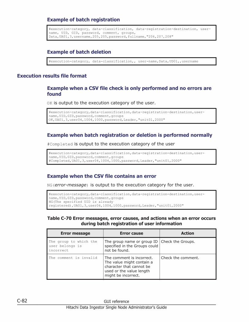
Example of batch registration
#execution-category, data-classification, data-registration-destination, user-name, UID, GID, password, comment, groups, Data,UA01,3,username,205,205,password,fullname,"206,207,208"
Example of batch deletion
#execution-category, data-classification,, user-name,Data,UD01,,username
Execution results file format
Example when a CSV file check is only performed and no errors arefound
OK is output to the execution category of the user.
#execution-category,data-classification,data-registration-destination,user-name,UID,GID,password,comment,groupsOK,UA01,3,user04,1004,1000,password,Leader,"unit01,2000"
Example when batch registration or deletion is performed normally
#Completed is output to the execution category of the user
#execution-category,data-classification,data-registration-destination,user-name,UID,GID,password,comment,groups#Completed,UA01,3,user04,1004,1000,password,Leader,"unit01,2000"
Example when the CSV file contains an error
NG(error-message) is output to the execution category for the user.
#execution-category,data-classification,data-registration-destination,user-name,UID,GID,password,comment,groupsNG(The specified UID is already registered),UA01,3,user04,1004,1000,password,Leader,"unit01,2000"
Table C-70 Error messages, error causes, and actions when an error occursduring batch registration of user information
Error message Error cause Action
The group to which theuser belongs isincorrect
The group name or group IDspecified in the Groups couldnot be found.
Check the Groups.
The comment is invalid The comment is incorrect.The value might contain acharacter that cannot beused or the value lengthmight be incorrect.
Check the comment.
C-82 GUI referenceHitachi Data Ingestor Single Node Administrator's Guide
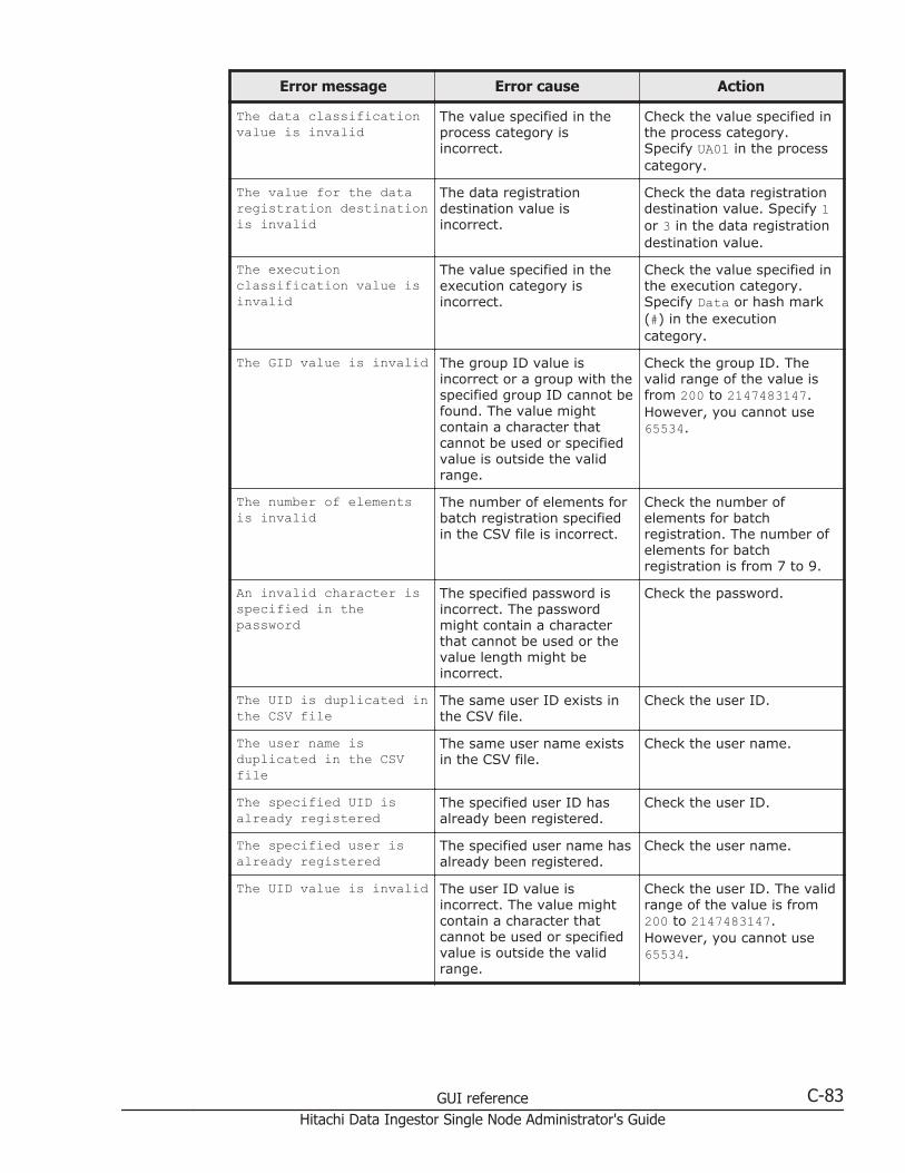
Error message Error cause Action
The data classificationvalue is invalid
The value specified in theprocess category isincorrect.
Check the value specified inthe process category.Specify UA01 in the processcategory.
The value for the dataregistration destinationis invalid
The data registrationdestination value isincorrect.
Check the data registrationdestination value. Specify 1or 3 in the data registrationdestination value.
The executionclassification value isinvalid
The value specified in theexecution category isincorrect.
Check the value specified inthe execution category.Specify Data or hash mark(#) in the executioncategory.
The GID value is invalid The group ID value isincorrect or a group with thespecified group ID cannot befound. The value mightcontain a character thatcannot be used or specifiedvalue is outside the validrange.
Check the group ID. Thevalid range of the value isfrom 200 to 2147483147.However, you cannot use65534.
The number of elementsis invalid
The number of elements forbatch registration specifiedin the CSV file is incorrect.
Check the number ofelements for batchregistration. The number ofelements for batchregistration is from 7 to 9.
An invalid character isspecified in thepassword
The specified password isincorrect. The passwordmight contain a characterthat cannot be used or thevalue length might beincorrect.
Check the password.
The UID is duplicated inthe CSV file
The same user ID exists inthe CSV file.
Check the user ID.
The user name isduplicated in the CSVfile
The same user name existsin the CSV file.
Check the user name.
The specified UID isalready registered
The specified user ID hasalready been registered.
Check the user ID.
The specified user isalready registered
The specified user name hasalready been registered.
Check the user name.
The UID value is invalid The user ID value isincorrect. The value mightcontain a character thatcannot be used or specifiedvalue is outside the validrange.
Check the user ID. The validrange of the value is from200 to 2147483147.However, you cannot use65534.
GUI reference C-83Hitachi Data Ingestor Single Node Administrator's Guide
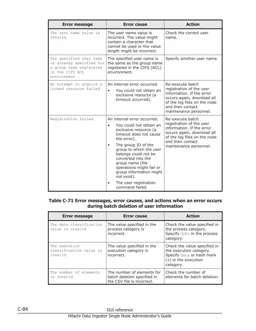
Error message Error cause Action
The user name value isinvalid
The user name value isincorrect. The value mightcontain a character thatcannot be used or the valuelength might be incorrect.
Check the correct username.
The specified user nameis already specified fora group name registeredin the CIFS ACLenvironment
The specified user name isthe same as the group nameregistered in the CIFS (ACL)environment.
Specify another user name.
An attempt to acquire alocked resource failed
An internal error occurred.
• You could not obtain anexclusive resource (atimeout occurred).
Re-execute batchregistration of the userinformation. If the erroroccurs again, download allof the log files on the nodeand then contactmaintenance personnel.
Registration failed An internal error occurred.
• You could not obtain anexclusive resource (atimeout does not causethe error).
• The group ID of thegroup to which the userbelongs could not beconverted into thegroup name (fileoperations might fail orgroup information mightnot exist).
• The user registrationcommand failed.
Re-execute batchregistration of the userinformation. If the erroroccurs again, download allof the log files on the nodeand then contactmaintenance personnel.
Table C-71 Error messages, error causes, and actions when an error occursduring batch deletion of user information
Error message Error cause Action
The data classificationvalue is invalid
The value specified in theprocess category isincorrect.
Check the value specified inthe process category.Specify UD01 in the processcategory.
The executionclassification value isinvalid
The value specified in theexecution category isincorrect.
Check the value specified inthe execution category.Specify Data or hash mark(#) in the executioncategory.
The number of elementsis invalid
The number of elements forbatch deletion specified inthe CSV file is incorrect.
Check the number ofelements for batch deletion.
C-84 GUI referenceHitachi Data Ingestor Single Node Administrator's Guide
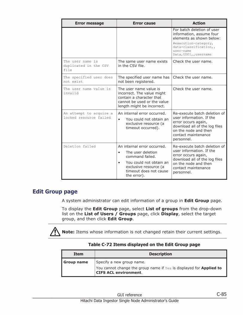
Error message Error cause Action
For batch deletion of userinformation, assume fourelements as shown below:#execution-category, data-classification,, user-nameData,UD01,,username
The user name isduplicated in the CSVfile
The same user name existsin the CSV file.
Check the user name.
The specified user doesnot exist
The specified user name hasnot been registered.
Check the user name.
The user name value isinvalid
The user name value isincorrect. The value mightcontain a character thatcannot be used or the valuelength might be incorrect.
Check the user name.
An attempt to acquire alocked resource failed
An internal error occurred.
• You could not obtain anexclusive resource (atimeout occurred).
Re-execute batch deletion ofuser information. If theerror occurs again,download all of the log fileson the node and thencontact maintenancepersonnel.
Deletion failed An internal error occurred.
• The user deletioncommand failed.
• You could not obtain anexclusive resource (atimeout does not causethe error).
Re-execute batch deletion ofuser information. If theerror occurs again,download all of the log fileson the node and thencontact maintenancepersonnel.
Edit Group pageA system administrator can edit information of a group in Edit Group page.
To display the Edit Group page, select List of groups from the drop-downlist on the List of Users / Groups page, click Display, select the targetgroup, and then click Edit Group.
Note: Items whose information is not changed retain their current settings.
Table C-72 Items displayed on the Edit Group page
Item Description
Group name Specify a new group name.
You cannot change the group name if Yes is displayed for Applied toCIFS ACL environment.
GUI reference C-85Hitachi Data Ingestor Single Node Administrator's Guide

Item Description
GID Displays the group ID.
Applied toCIFS ACLenvironment
Displays whether ACLs are set for the group.
Users in group Change the users who belong to the group.
• To add users to the group:
In List of selectable users, select the users you want to add,and then click the button. You can select only the usersdisplayed in Selected users.
• To delete users from the group:
In Selected users, select the users you want to delete, and thenclick the button.
Add Group pageA system administrator can add a group in Add Group page.
To display the Add Group page, select List of groups from the drop-downlist on the List of Users / Groups page, click Display, and then click AddNew Group.
Note: Make sure that the number of groups is not more than 2,000.
Table C-73 Items displayed in the Add Group page
Item Description
Group name Enter the group name.
You cannot enter any group name that has already been registered inthe HDI system, on the NIS server, or on the LDAP server for userauthentication.
Enter a maximum of 16 characters. The first character must be analphanumeric character. You can use any alphanumeric character,hyphen (-), and underscore (_) after the first character.
In Windows, the entered value is not case sensitive. Specify a namethat is unique regardless of whether upper-case or lower-casealphabetic characters are used.
If ACL functionality is to be used for the group being added, youcannot specify a name that is the same as that of any user configuredto access CIFS shares.
Also, you cannot specify the group name shown in Table E-3 List ofreserved words for the group name on page E-3 because the groupname is reserved by the OS.
GID Enter the group ID.
Specify a value from 200 to 2147483147. You cannot specify 65534 orthe group ID that has already been registered in the HDI system, onthe NIS server, or on the LDAP server for user authentication. In
C-86 GUI referenceHitachi Data Ingestor Single Node Administrator's Guide

Item Description
addition, when user mapping is being used, you cannot specify thegroup IDs within the ID range set by user mapping.
Apply to CIFSACLenvironment
Select this check box when setting an ACL for the adding group.
Users in group Specify the users you want to add to the group.
In List of selectable users, select the users you want to add to thegroup, and then click the button. You can add only the usersdisplayed in Selected users.
To delete users from the group, in Selected users, select the usersyou want to delete, and then click the button.
Backup Configuration dialog boxYou can download the system configuration file (the file in which systemconfiguration information is archived) and save it in storage media outsidethe system, and upload the downloaded system configuration file if an erroroccurs.
Note:
• If the system configuration file (the file in which system configurationinformation is archived) is not downloaded, you might not be able toproperly restore the system after a failure occurs in a system disk orstorage system. Therefore, download the system configuration file, andthen save the file to storage media outside of the system.
• If the periodic saving of system configuration information is enabled andyou change the system configuration, you need to manually save thesystem configuration information and download the system configurationinformation file.
• If an error occurs while periodic saving of system configurationinformation is enabled, and you can still display the BackupConfiguration dialog box, disable periodic saving. Periodic saving mightoverwrite correct data with incorrect data generated after the failure.
• The system configuration information file contains password informationfor system administrators, end users, and administrators of externalservers. Be especially careful when managing a downloaded systemconfiguration information file.
• The system administrator cannot edit a downloaded system configurationfile. In addition, the system configuration file cannot be used in a differentversion of the HDI system.
• Make sure that you set the time for periodic saving to a time periodduring which no jobs of the NDMP functionality are running. In addition,make sure that you do not execute a command or use the GUI at the timewhen periodic saving is performed.
GUI reference C-87Hitachi Data Ingestor Single Node Administrator's Guide

To display the Backup Configuration dialog box, click BackupConfiguration in the Settings area of the host-name window.
Save System Settings Menu pageYou can download the system configuration information file, and upload thesystem configuration information file that has been downloaded.
The Save System Settings Menu page appears first when the BackupConfiguration dialog box is displayed.
Table C-74 Items displayed on the Save System Settings Menu page
Buttons Description See
Save AllSystemSettings button
Saves system configuration information anddownloads the system configuration information file.Settings related to periodic saving can also bespecified.
Save All SystemSettings pageon page C-88
Upload SavedData button
Upload the system configuration information file onthe node according to the instructions frommaintenance personnel, or delete the uploaded filefrom the node.
Upload SavedData page onpage C-92
Save All System Settings pageYou can download the system configuration information file.
Note: It takes about 4 minutes to save the system configuration information.When there is a heavy load on a node, a save operation for the system diskmight automatically stop to reduce the load on the node (The processing ofOS disks times out after about 5 minutes from the start of the saveprocessing.). In this case, after the load on the node is reduced andstabilized, retry the save operation.
To display the Save All System Settings page, click the Save All SystemSettings button on the Save System Settings Menu page.
Table C-75 Items displayed on the Save All System Settings page
Item Description
Save status Status Displays the save and restore status of thesystem configuration information.
NormalThe processing to save or restore thesystem configuration information hascompleted.
Now saving...The system configuration information isbeing saved.
Now restoring...
C-88 GUI referenceHitachi Data Ingestor Single Node Administrator's Guide

Item Description
The system configuration information isbeing restored.
Do not attempt to save or download the file ifthe displayed status is not Normal.
Last save date Displays the date and time when the systemconfiguration information was last saved. If nodata has been saved, a hyphen (-) isdisplayed.
Saveschedule
Schedule settingstatus
Displays whether the periodic saving of systemconfiguration information is enabled.
OnPeriodic saving is enabled.
OffPeriodic saving is disabled.
Schedule interval Displays the interval at which the periodicsaving of system configuration information isexecuted.
DailyPeriodic saving is executed every day.
WeeklyPeriodic saving is executed on the specifiedday of the week. The specified day of theweek is also displayed.
MonthlyPeriodic saving is executed on the specifieddate every month. The specified date isalso displayed.
Schedule time Displays the time that the periodic saving ofsystem configuration information starts.
Output setting Displays the location in which the systemconfiguration information file will be savedwhen periodic saving is executed.
Server transfer(HCP)The system configuration information filewill be saved in the HCP system.
Server transfer(FTP)The system configuration information filewill be transferred to the FTP server.
directory-path
The system configuration information filewill be saved in the displayed directory inthe home directory or file system.
If the system configuration information file isnot to be output, a hyphen (-) is displayed.
FTP server Displays the IP address or host name of theFTP server to which the system configurationinformation file is to be transferred when the
GUI reference C-89Hitachi Data Ingestor Single Node Administrator's Guide

Item Description
periodic saving of system configurationinformation is executed.
If no information has been set, a hyphen (-) isdisplayed.
User name Displays the name of the user who logs on tothe FTP server for the periodic saving ofsystem configuration information.
If no information has been set, a hyphen (-) isdisplayed.
Directory Displays the directory on the FTP server towhich the system configuration information fileis to be transferred when the periodic saving ofsystem configuration information is executed.
If no information has been set, a hyphen (-) isdisplayed.
Download button Downloads the system configurationinformation.
Enable Scheduling button or DisableScheduling button
Enables or disables the periodic saving ofsystem configuration information.
You can check the settings in Schedulesetting status on the Save All SystemSettings page.
Modify Schedule button Sets the periodic saving interval for systemconfiguration information. The ScheduleSettings for Saving All System Settingspage is displayed (Schedule Settings for SavingAll System Settings page on page C-90).
Schedule Settings for Saving All System Settings pageYou can set the periodic saving interval for system configuration information.
Note: Saving system configuration information imposes heavy loads on thenode. When specifying a date and time for an interval for periodic saving,avoid time periods during which you expect heavy access to the node (suchas when the system administrator performs maintenance tasks or when endusers use file systems).When the start time of periodic saving is set in the switchover time zone forDaylight Saving Time, save operations might be performed twice or might notbe performed on the day of the switch to or from Daylight Saving Time.
To display the Schedule Settings for Saving All System Settings page,click Modify Schedule on the Save All System Settings page.
C-90 GUI referenceHitachi Data Ingestor Single Node Administrator's Guide
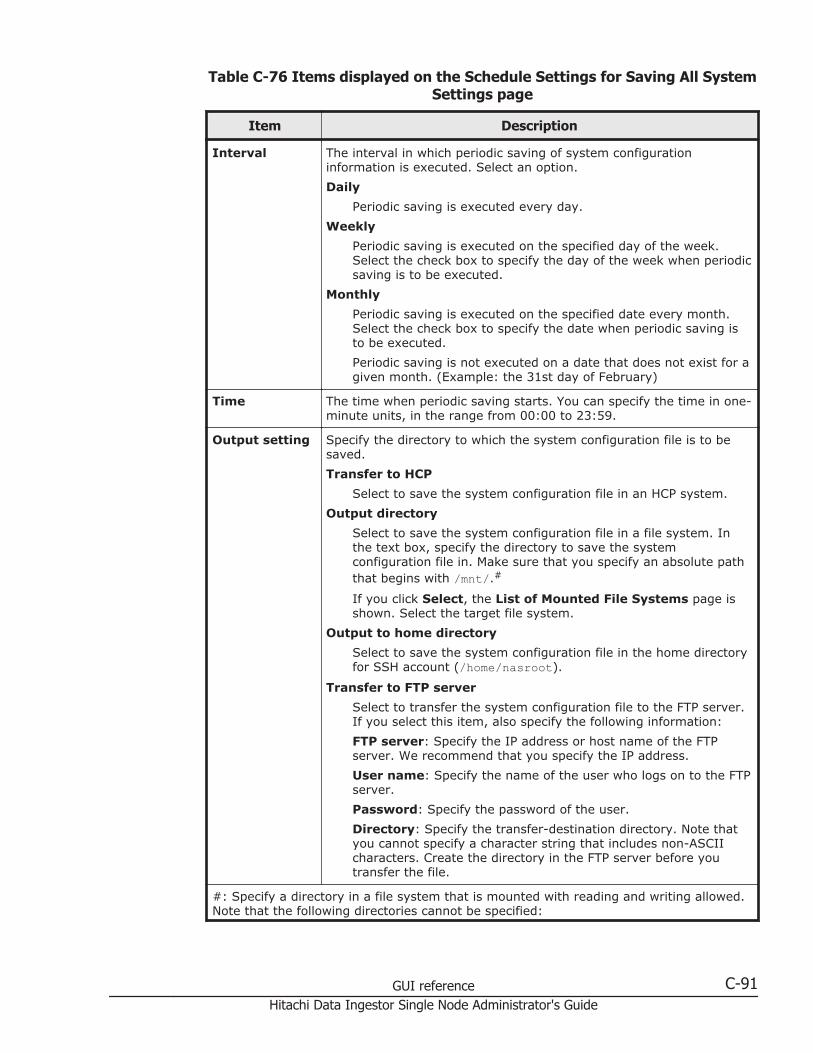
Table C-76 Items displayed on the Schedule Settings for Saving All SystemSettings page
Item Description
Interval The interval in which periodic saving of system configurationinformation is executed. Select an option.
Daily
Periodic saving is executed every day.
Weekly
Periodic saving is executed on the specified day of the week.Select the check box to specify the day of the week when periodicsaving is to be executed.
Monthly
Periodic saving is executed on the specified date every month.Select the check box to specify the date when periodic saving isto be executed.
Periodic saving is not executed on a date that does not exist for agiven month. (Example: the 31st day of February)
Time The time when periodic saving starts. You can specify the time in one-minute units, in the range from 00:00 to 23:59.
Output setting Specify the directory to which the system configuration file is to besaved.
Transfer to HCP
Select to save the system configuration file in an HCP system.
Output directory
Select to save the system configuration file in a file system. Inthe text box, specify the directory to save the systemconfiguration file in. Make sure that you specify an absolute paththat begins with /mnt/.#
If you click Select, the List of Mounted File Systems page isshown. Select the target file system.
Output to home directory
Select to save the system configuration file in the home directoryfor SSH account (/home/nasroot).
Transfer to FTP server
Select to transfer the system configuration file to the FTP server.If you select this item, also specify the following information:
FTP server: Specify the IP address or host name of the FTPserver. We recommend that you specify the IP address.
User name: Specify the name of the user who logs on to the FTPserver.
Password: Specify the password of the user.
Directory: Specify the transfer-destination directory. Note thatyou cannot specify a character string that includes non-ASCIIcharacters. Create the directory in the FTP server before youtransfer the file.
#: Specify a directory in a file system that is mounted with reading and writing allowed.Note that the following directories cannot be specified:
GUI reference C-91Hitachi Data Ingestor Single Node Administrator's Guide
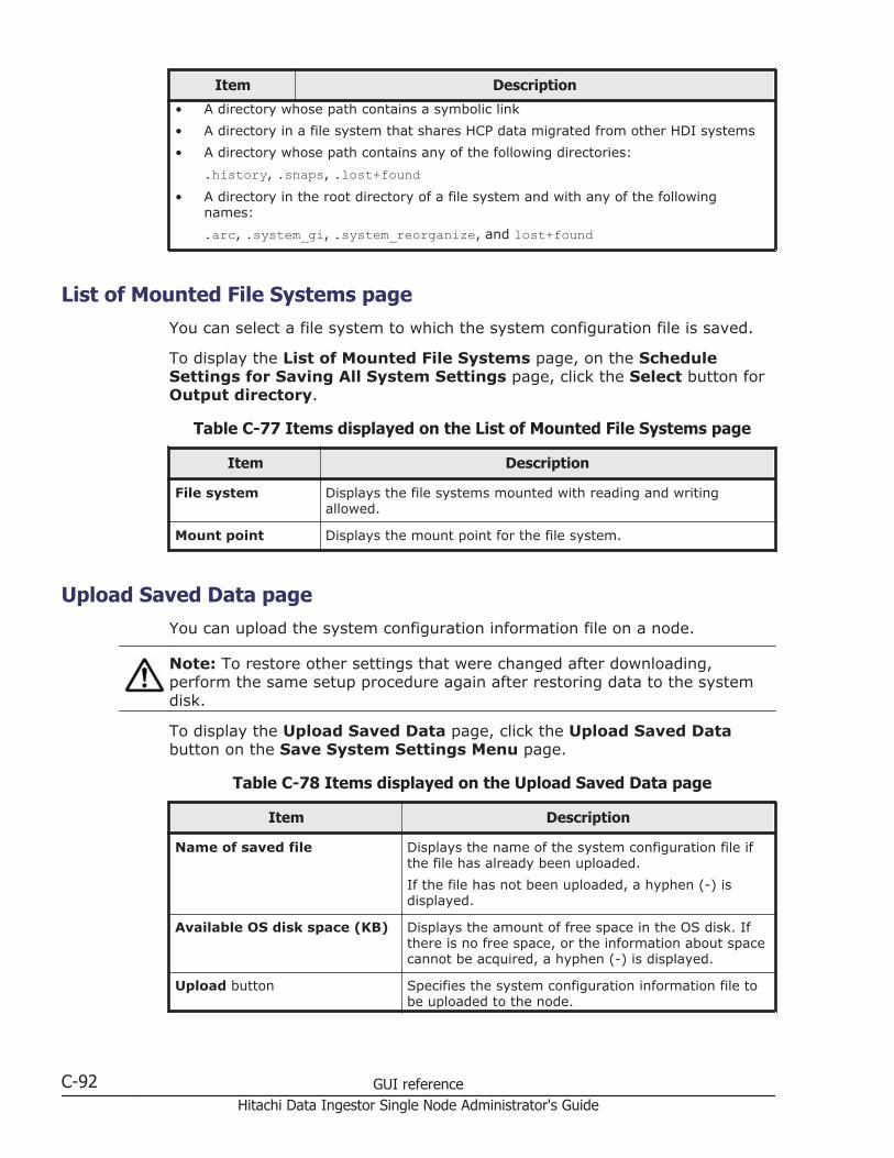
Item Description
• A directory whose path contains a symbolic link
• A directory in a file system that shares HCP data migrated from other HDI systems
• A directory whose path contains any of the following directories:
.history, .snaps, .lost+found• A directory in the root directory of a file system and with any of the following
names:
.arc, .system_gi, .system_reorganize, and lost+found
List of Mounted File Systems pageYou can select a file system to which the system configuration file is saved.
To display the List of Mounted File Systems page, on the ScheduleSettings for Saving All System Settings page, click the Select button forOutput directory.
Table C-77 Items displayed on the List of Mounted File Systems page
Item Description
File system Displays the file systems mounted with reading and writingallowed.
Mount point Displays the mount point for the file system.
Upload Saved Data pageYou can upload the system configuration information file on a node.
Note: To restore other settings that were changed after downloading,perform the same setup procedure again after restoring data to the systemdisk.
To display the Upload Saved Data page, click the Upload Saved Databutton on the Save System Settings Menu page.
Table C-78 Items displayed on the Upload Saved Data page
Item Description
Name of saved file Displays the name of the system configuration file ifthe file has already been uploaded.
If the file has not been uploaded, a hyphen (-) isdisplayed.
Available OS disk space (KB) Displays the amount of free space in the OS disk. Ifthere is no free space, or the information about spacecannot be acquired, a hyphen (-) is displayed.
Upload button Specifies the system configuration information file tobe uploaded to the node.
C-92 GUI referenceHitachi Data Ingestor Single Node Administrator's Guide
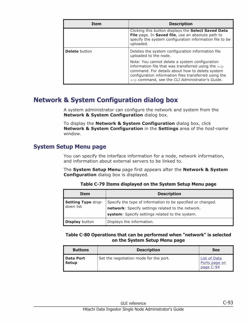
Item Description
Clicking this button displays the Select Saved DataFile page. In Saved file, use an absolute path tospecify the system configuration information file to beuploaded.
Delete button Deletes the system configuration information fileuploaded to the node.
Note: You cannot delete a system configurationinformation file that was transferred using the scpcommand. For details about how to delete systemconfiguration information files transferred using thescp command, see the CLI Administrator's Guide.
Network & System Configuration dialog boxA system administrator can configure the network and system from theNetwork & System Configuration dialog box.
To display the Network & System Configuration dialog box, clickNetwork & System Configuration in the Settings area of the host-namewindow.
System Setup Menu pageYou can specify the interface information for a node, network information,and information about external servers to be linked to.
The System Setup Menu page first appears after the Network & SystemConfiguration dialog box is displayed.
Table C-79 Items displayed on the System Setup Menu page
Item Description
Setting Type drop-down list
Specify the type of information to be specified or changed.
network: Specify settings related to the network.
system: Specify settings related to the system.
Display button Displays the information.
Table C-80 Operations that can be performed when "network" is selectedon the System Setup Menu page
Buttons Description See
Data PortSetup
Set the negotiation mode for the port. List of DataPorts page onpage C-94
GUI reference C-93Hitachi Data Ingestor Single Node Administrator's Guide
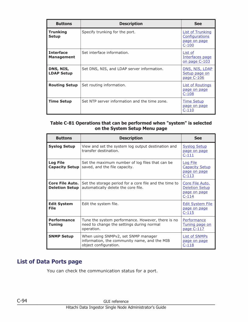
Buttons Description See
TrunkingSetup
Specify trunking for the port. List of TrunkingConfigurationspage on pageC-100
InterfaceManagement
Set interface information. List ofInterfaces pageon page C-103
DNS, NIS,LDAP Setup
Set DNS, NIS, and LDAP server information. DNS, NIS, LDAPSetup page onpage C-106
Routing Setup Set routing information. List of Routingspage on pageC-108
Time Setup Set NTP server information and the time zone. Time Setuppage on pageC-110
Table C-81 Operations that can be performed when "system" is selectedon the System Setup Menu page
Buttons Description See
Syslog Setup View and set the system log output destination andtransfer destination.
Syslog Setuppage on pageC-111
Log FileCapacity Setup
Set the maximum number of log files that can besaved, and the file capacity.
Log FileCapacity Setuppage on pageC-113
Core File Auto.Deletion Setup
Set the storage period for a core file and the time toautomatically delete the core file.
Core File Auto.Deletion Setuppage on pageC-114
Edit SystemFile
Edit the system file. Edit System Filepage on pageC-115
PerformanceTuning
Tune the system performance. However, there is noneed to change the settings during normaloperation.
PerformanceTuning page onpage C-117
SNMP Setup When using SNMPv2, set SNMP managerinformation, the community name, and the MIBobject configuration.
List of SNMPspage on pageC-118
List of Data Ports pageYou can check the communication status for a port.
C-94 GUI referenceHitachi Data Ingestor Single Node Administrator's Guide

To display the List of Data Ports page, select network from the drop-downlist on the System Setup Menu page, click the Display button, and thenclick the Data Port Setup button.
Table C-82 Items displayed on the List of Data Ports page
Item Description
Data port The name of the port (either mng0 or ethn).
Media type The media type of the port.
CopperMetal cables are supported.
Negotiation mode The negotiation mode used by the port.
AutoDisplayed if auto negotiation is used forcommunication on a port that supports metal cables.
1000Base Full Duplex(Auto Negotiation)Displayed if 1000Base full duplex communication isused. Auto negotiation is also used.
100Base Full DuplexDisplayed if 100Base full duplex communication isused. The negotiation mode is fixed.
100Base Full Duplex(Auto Negotiation)#
Displayed if 100Base full duplex communication isused. Auto negotiation is also used.
100Base Half DuplexDisplayed if 100Base half duplex communication isused. The negotiation mode is fixed.
100Base Half Duplex(Auto Negotiation)#
Displayed if 100Base half duplex communication isused. Auto negotiation is also used.
Connectedstatus
Link status The link status.
UpThe link is operating normally.
DownThe link is disconnected. Check the negotiation modeof the switch connected to the port, and then set thenegotiation mode again.
ErrorThe link cannot be recognized. An error might haveoccurred in the HDI system. Download all log files,and contact maintenance personnel.
Speed The current transfer rate.
1000BaseCommunication is being performed at 1 Gbps.
100BaseCommunication is being performed at 100 Mbps.
GUI reference C-95Hitachi Data Ingestor Single Node Administrator's Guide

Item Description10Base
Communication is being performed at 10 Mbps. Notethat 10BASE is not a recommended transfer rate.Review the settings of the switch connected to theport to make sure the transfer rate is at least100BASE.
-Communication is not being performed (Link statusis Down).
Duplex The current communication method.
FullFull duplex communication is used.
This is also displayed when the negotiation mode ofthe connected switch is auto negotiation andNegotiation mode of the HDI port is Auto.
HalfHalf duplex communication is used.
This is also displayed when the negotiation mode ofthe connected switch is fixed mode (non-auto-negotiation 100Base half duplex or 100Base fullduplex) and Negotiation mode of the HDI port isAuto.
-Communication is not being performed (Link statusis Down).
Negotiation Mode Setupbutton
Changes the negotiation mode of a port. Select the checkbox for the port whose negotiation mode you want tochange, and then click the button. The Negotiation ModeSetup page opens (Negotiation Mode Setup page on pageC-96).
#: If the negotiation mode is set to 100Base Full Duplex or 100Base Half Duplex inversions earlier than 3.2.3, then after an upgrade installation, the negotiation mode isdisplayed as 100Base Full Duplex(Auto Negotiation) or 100Base Half Duplex(AutoNegotiation).
Negotiation Mode Setup pageYou can change the negotiation mode for a port.
Note: Before you use this page, see Before changing the negotiation modefor the port: on page C-97.
To display the Negotiation Mode Setup page, select network from thedrop-down list on the System Setup Menu page, click the Display button,and then click the Data Port Setup button. Then, on the List of Data Portspage, select the check box for the port for which you want to change thenegotiation mode, and then click the Negotiation Mode Setup button.
C-96 GUI referenceHitachi Data Ingestor Single Node Administrator's Guide
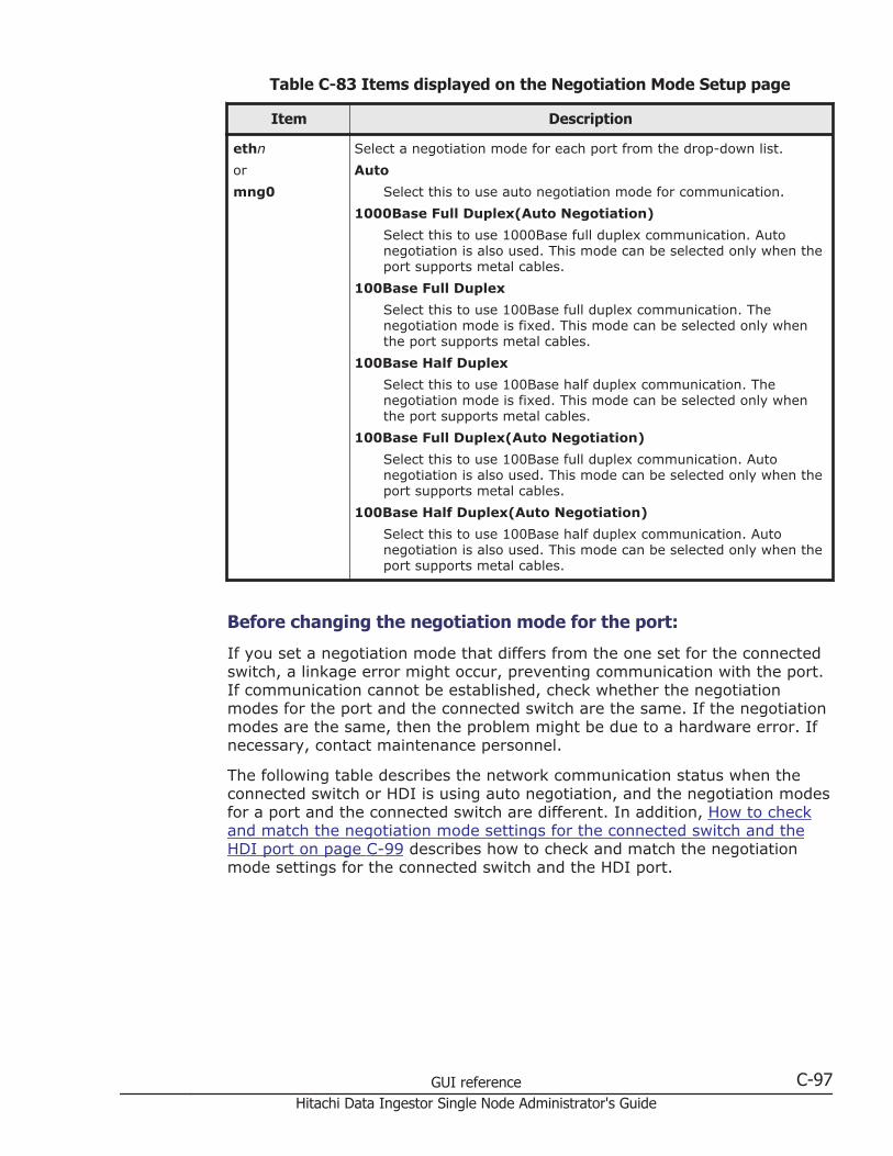
Table C-83 Items displayed on the Negotiation Mode Setup page
Item Description
ethn
or
mng0
Select a negotiation mode for each port from the drop-down list.
Auto
Select this to use auto negotiation mode for communication.
1000Base Full Duplex(Auto Negotiation)
Select this to use 1000Base full duplex communication. Autonegotiation is also used. This mode can be selected only when theport supports metal cables.
100Base Full Duplex
Select this to use 100Base full duplex communication. Thenegotiation mode is fixed. This mode can be selected only whenthe port supports metal cables.
100Base Half Duplex
Select this to use 100Base half duplex communication. Thenegotiation mode is fixed. This mode can be selected only whenthe port supports metal cables.
100Base Full Duplex(Auto Negotiation)
Select this to use 100Base full duplex communication. Autonegotiation is also used. This mode can be selected only when theport supports metal cables.
100Base Half Duplex(Auto Negotiation)
Select this to use 100Base half duplex communication. Autonegotiation is also used. This mode can be selected only when theport supports metal cables.
Before changing the negotiation mode for the port:
If you set a negotiation mode that differs from the one set for the connectedswitch, a linkage error might occur, preventing communication with the port.If communication cannot be established, check whether the negotiationmodes for the port and the connected switch are the same. If the negotiationmodes are the same, then the problem might be due to a hardware error. Ifnecessary, contact maintenance personnel.
The following table describes the network communication status when theconnected switch or HDI is using auto negotiation, and the negotiation modesfor a port and the connected switch are different. In addition, How to checkand match the negotiation mode settings for the connected switch and theHDI port on page C-99 describes how to check and match the negotiationmode settings for the connected switch and the HDI port.
GUI reference C-97Hitachi Data Ingestor Single Node Administrator's Guide

Table C-84 Network communication status when auto negotiation is beingused, and the negotiation modes for a port and the connected switch are
different
Negotiation mode for theport
Negotiation mode for theconnected switch
Value displayed inConnected status on theList of Data Ports page
Auto negotiation mode
(when Auto is set)
Auto negotiation mode The communication status ischosen, in the followingorder, depending on thenegotiation modes of theport and the connectedswitch:#1
1. 1000Base full duplex
2. 1000Base half duplex
3. 100Base full duplex
4. 100Base half duplex
5. 10Base full duplex
6. 10Base half duplex
Note that 10Base is not arecommendedcommunication speed.Correct the setting of theconnected switch so that thecommunication speed is100Base or greater.
100Base half duplex 100Base half duplex
100Base full duplex 100Base half duplex#2
100Base half duplex
(when 100Base HalfDuplex is set)
Auto negotiation mode 100Base half duplex
100Base full duplex
(when 100Base FullDuplex is set)
Auto negotiation mode 100Base full duplex#2
Auto negotiation mode:
• 1000Base full duplex
(when 1000Base FullDuplex(Auto Negotiation)is set)
Auto negotiation mode 1000Base full duplex
Auto negotiation mode:
• 100Base half duplex
(when 100Base HalfDuplex(Auto Negotiation)is set)
Auto negotiation mode 100Base half duplex
100Base half duplex 100Base half duplex
100Base full duplex 100Base half duplex#2
Auto negotiation mode:
• 100Base full duplex
Auto negotiation mode 100Base full duplex
C-98 GUI referenceHitachi Data Ingestor Single Node Administrator's Guide
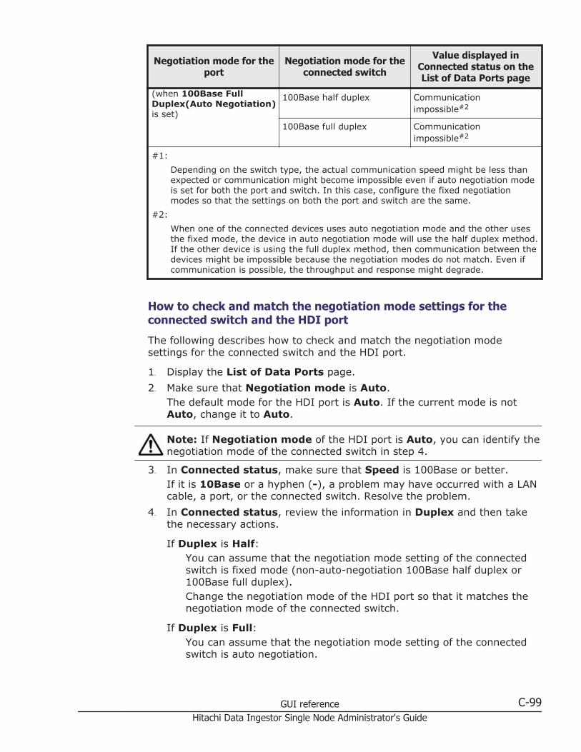
Negotiation mode for theport
Negotiation mode for theconnected switch
Value displayed inConnected status on theList of Data Ports page
(when 100Base FullDuplex(Auto Negotiation)is set)
100Base half duplex Communicationimpossible#2
100Base full duplex Communicationimpossible#2
#1:
Depending on the switch type, the actual communication speed might be less thanexpected or communication might become impossible even if auto negotiation modeis set for both the port and switch. In this case, configure the fixed negotiationmodes so that the settings on both the port and switch are the same.
#2:
When one of the connected devices uses auto negotiation mode and the other usesthe fixed mode, the device in auto negotiation mode will use the half duplex method.If the other device is using the full duplex method, then communication between thedevices might be impossible because the negotiation modes do not match. Even ifcommunication is possible, the throughput and response might degrade.
How to check and match the negotiation mode settings for theconnected switch and the HDI port
The following describes how to check and match the negotiation modesettings for the connected switch and the HDI port.
1. Display the List of Data Ports page.
2. Make sure that Negotiation mode is Auto.The default mode for the HDI port is Auto. If the current mode is notAuto, change it to Auto.
Note: If Negotiation mode of the HDI port is Auto, you can identify thenegotiation mode of the connected switch in step 4.
3. In Connected status, make sure that Speed is 100Base or better.If it is 10Base or a hyphen (-), a problem may have occurred with a LANcable, a port, or the connected switch. Resolve the problem.
4. In Connected status, review the information in Duplex and then takethe necessary actions.
If Duplex is Half:You can assume that the negotiation mode setting of the connectedswitch is fixed mode (non-auto-negotiation 100Base half duplex or100Base full duplex).Change the negotiation mode of the HDI port so that it matches thenegotiation mode of the connected switch.
If Duplex is Full:You can assume that the negotiation mode setting of the connectedswitch is auto negotiation.
GUI reference C-99Hitachi Data Ingestor Single Node Administrator's Guide

If you already changed Negotiation mode of the HDI port to Auto instep 2, you do not need to cancel the change.
List of Trunking Configurations pageYou can check the trunking settings.
Note:
• When an interface has been created for a port on which trunking will beset up, edited, or deleted, make sure that the resource group is runningnormally or was stopped without any problems.
• When you edit the trunking settings, you will temporarily be unable tocommunicate with or use any services via the interface of the target port.
• If trunking settings are configured during operation, the system deletesthe interface information (including VLAN settings) set for the port to betrunked and the routing information set for the interface.
• If trunking is released, the system automatically deletes the interfaceinformation (including VLAN settings) and routing information set for theport for which trunking is to be released.
• If you have changed the trunking settings, review the interfaceinformation, routing information, and VLAN settings.
• You cannot trunk ports that have different negotiation modes or differentcommunication speeds or methods. Check the List of Data Ports page inthe Network & System Configuration dialog box, and trunk only portsthat have identical Negotiation mode, Speed, and Duplex settings.
To display the List of Trunking Configurations page, select network fromthe drop-down list on the System Setup Menu page, click the Displaybutton, and then click the Trunking Setup button.
Table C-85 Items displayed on the List of Trunking Configurations page
Item Description
Trunking configuration A trunking configuration
Port A port name.
agrnumber
The port is a link aggregation port.
rdnnumber
The port is a link alternation port.
ethnumber
The name of a port. When trunking is used, the namesof the ports making up trunking are displayed.
Trunking type The type of trunking being used.
Link AggregationThe port is a link aggregation port.
Link Alternation
C-100 GUI referenceHitachi Data Ingestor Single Node Administrator's Guide
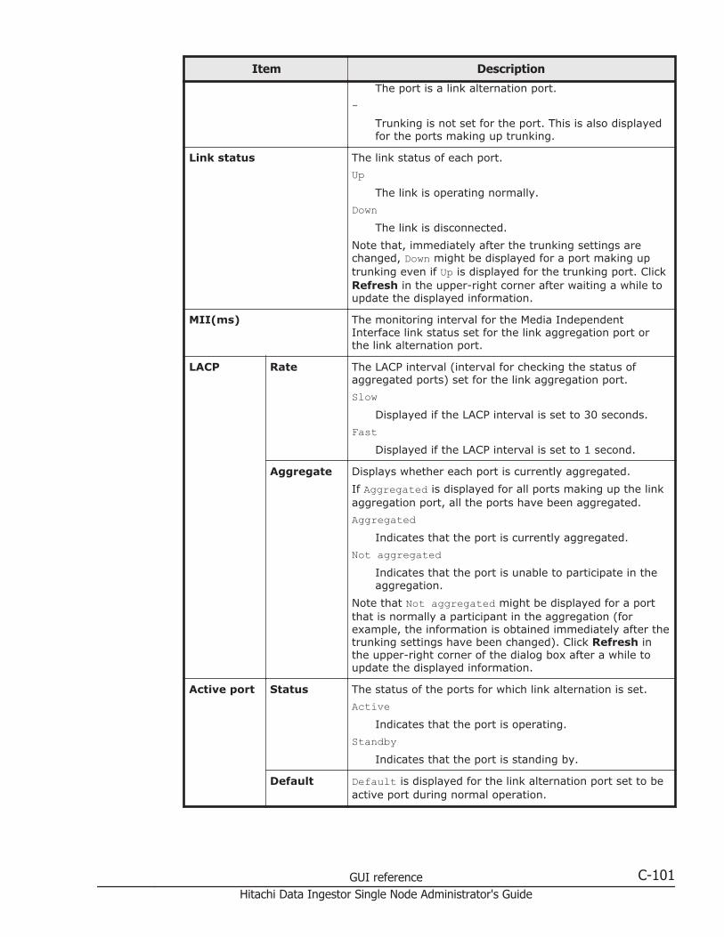
Item Description
The port is a link alternation port.
-Trunking is not set for the port. This is also displayedfor the ports making up trunking.
Link status The link status of each port.
UpThe link is operating normally.
DownThe link is disconnected.
Note that, immediately after the trunking settings arechanged, Down might be displayed for a port making uptrunking even if Up is displayed for the trunking port. ClickRefresh in the upper-right corner after waiting a while toupdate the displayed information.
MII(ms) The monitoring interval for the Media IndependentInterface link status set for the link aggregation port orthe link alternation port.
LACP Rate The LACP interval (interval for checking the status ofaggregated ports) set for the link aggregation port.
SlowDisplayed if the LACP interval is set to 30 seconds.
FastDisplayed if the LACP interval is set to 1 second.
Aggregate Displays whether each port is currently aggregated.
If Aggregated is displayed for all ports making up the linkaggregation port, all the ports have been aggregated.
AggregatedIndicates that the port is currently aggregated.
Not aggregatedIndicates that the port is unable to participate in theaggregation.
Note that Not aggregated might be displayed for a portthat is normally a participant in the aggregation (forexample, the information is obtained immediately after thetrunking settings have been changed). Click Refresh inthe upper-right corner of the dialog box after a while toupdate the displayed information.
Active port Status The status of the ports for which link alternation is set.
ActiveIndicates that the port is operating.
StandbyIndicates that the port is standing by.
Default Default is displayed for the link alternation port set to beactive port during normal operation.
GUI reference C-101Hitachi Data Ingestor Single Node Administrator's Guide

Item Description
Create Link Aggregationbutton
Click to set link aggregation. Select the ports you want tospecify for link aggregation, and then click this button. TheLink Aggregation Setup page opens (Link AggregationSetup page on page C-102).
Create Link Alternationbutton
Click to set link alternation. Select the two ports you wantto specify for link alternation, and then click this button.The Link Alternation Setup page opens (Link AlternationSetup page on page C-102).
Edit Trunking button Click to change the trunking settings. Select the portswhose settings you want to change, and then click thisbutton. The Link Aggregation Setup page or the LinkAlternation Setup page opens (Link Aggregation Setuppage on page C-102 or Link Alternation Setup page onpage C-102).
Release Trunking button Click to release trunking. Select the trunking you want torelease, and then click this button.
Change Active PortStatus button
Click to change the link. Select the port whose link statusyou want to change, and then click this button.
Link Aggregation Setup pageYou can set up link aggregation.
To display the Link Aggregation Setup page, select network from thedrop-down list on the System Setup Menu page, click the Display button,and then click the Trunking Setup button. Then, on the List of TrunkingConfigurations page, select the ports for which you want to set up linkaggregation, and then click the Create Link Aggregation button.
Table C-86 Items displayed on the Link Aggregation Setup page
Item Description
LACP ratedrop-down list
Use this drop-down list to select the interval for checking the status ofthe ports making up a link aggregation port.
Slow: Checks the status every 30 seconds.
Fast: Checks the status every second.
MII Specify the interval at which the status of the Media IndependentInterface link is checked. You can specify a value from 1 to 100 in 10-ms units.
Link Alternation Setup pageYou can set up link alternation.
To display the Link Alternation Setup page, select network from the drop-down list on the System Setup Menu page, click the Display button, andthen click the Trunking Setup button. Then, on the List of Trunking
C-102 GUI referenceHitachi Data Ingestor Single Node Administrator's Guide
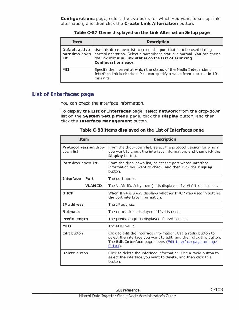
Configurations page, select the two ports for which you want to set up linkalternation, and then click the Create Link Alternation button.
Table C-87 Items displayed on the Link Alternation Setup page
Item Description
Default activeport drop-downlist
Use this drop-down list to select the port that is to be used duringnormal operation. Select a port whose status is normal. You can checkthe link status in Link status on the List of TrunkingConfigurations page.
MII Specify the interval at which the status of the Media IndependentInterface link is checked. You can specify a value from 1 to 100 in 10-ms units.
List of Interfaces pageYou can check the interface information.
To display the List of Interfaces page, select network from the drop-downlist on the System Setup Menu page, click the Display button, and thenclick the Interface Management button.
Table C-88 Items displayed on the List of Interfaces page
Item Description
Protocol version drop-down list
From the drop-down list, select the protocol version for whichyou want to check the interface information, and then click theDisplay button.
Port drop-down list From the drop-down list, select the port whose interfaceinformation you want to check, and then click the Displaybutton.
Interface Port The port name.
VLAN ID The VLAN ID. A hyphen (-) is displayed if a VLAN is not used.
DHCP When IPv4 is used, displays whether DHCP was used in settingthe port interface information.
IP address The IP address
Netmask The netmask is displayed if IPv4 is used.
Prefix length The prefix length is displayed if IPv6 is used.
MTU The MTU value.
Edit button Click to edit the interface information. Use a radio button toselect the interface you want to edit, and then click this button.The Edit Interface page opens (Edit Interface page on pageC-104).
Delete button Click to delete the interface information. Use a radio button toselect the interface you want to delete, and then click thisbutton.
GUI reference C-103Hitachi Data Ingestor Single Node Administrator's Guide

Item Description
Add button Click to set interface information. The Add Interface pageopens (Add Interface page on page C-105).
Edit Interface pageYou can change the interface information.
Note: After changing the interface information, perform the following ifnecessary:
• If you have changed the MTU value, make sure that communication canbe performed between the client and the node at the highest MTU value.To do this, use the ping command from the client after making thechange. If the MTU value is set correctly, but the client cannotcommunicate with the node, a peripheral device or client might be thecause of the problem. Check the peripheral device and client settings.
• If you have changed the IP address, Netmask, or Prefix length valuefor mng0, after clicking the OK button, click the Close button in the dialogbox that appears. To continue operation, wait a while, and then log on tothe GUI.
• If the GUI does not respond, click the x button in the title bar to close thewindow.
To display the Edit Interface page, select network from the drop-down liston the System Setup Menu page, click the Display button, and then clickthe Interface Management button. Then, on the List of Interfaces page,select the radio button for the interface for which you want to edit theinformation, and then click the Edit button.
Table C-89 Items displayed on the Edit Interface page
Item Description
Port The port name.
VLAN ID The VLAN ID. A hyphen (-) is displayed if a VLAN is not used.
If the mng0 information is edited, this item is not displayed.
IP address# Specify the IP address.
Netmask Specify the netmask if IPv4 is used.
Prefix length Specify the prefix length if IPv6 is used.
MTU Specify the MTU value of an interface. Changing the MTU value of theinterface allows you to use the Jumbo Frame packet. Specify a valueranging from 1280 to 9216. The value specified here is applied to boththe IPv4 and IPv6 environments.
Note that the MTU value for mng0 cannot be changed.
#: The IP addresses of the networks listed below cannot be specified. If specifying one ofthese is unavoidable, contact the Technical Support Center.
C-104 GUI referenceHitachi Data Ingestor Single Node Administrator's Guide
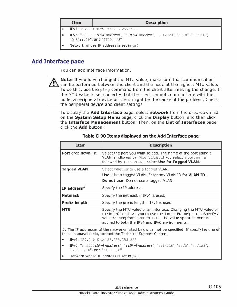
Item Description
• IPv4: 127.0.0.0 to 127.255.255.255• IPv6: "::ffff:IPv4-address", "::IPv4-address", "::1/128", "::/0", "::/128",
"fe80::/10", and "ff00::/8"
• Network whose IP address is set in pm0
Add Interface pageYou can add interface information.
Note: If you have changed the MTU value, make sure that communicationcan be performed between the client and the node at the highest MTU value.To do this, use the ping command from the client after making the change. Ifthe MTU value is set correctly, but the client cannot communicate with thenode, a peripheral device or client might be the cause of the problem. Checkthe peripheral device and client settings.
To display the Add Interface page, select network from the drop-down liston the System Setup Menu page, click the Display button, and then clickthe Interface Management button. Then, on the List of Interfaces page,click the Add button.
Table C-90 Items displayed on the Add Interface page
Item Description
Port drop-down list Select the port you want to add. The name of the port using aVLAN is followed by (Use VLAN). If you select a port namefollowed by (Use VLAN), select Use for Tagged VLAN.
Tagged VLAN Select whether to use a tagged VLAN.
Use: Use a tagged VLAN. Enter any VLAN ID for VLAN ID.
Do not use: Do not use a tagged VLAN.
IP address# Specify the IP address.
Netmask Specify the netmask if IPv4 is used.
Prefix length Specify the prefix length if IPv6 is used.
MTU Specify the MTU value of an interface. Changing the MTU value ofthe interface allows you to use the Jumbo Frame packet. Specify avalue ranging from 1280 to 9216. The value specified here isapplied to both the IPv4 and IPv6 environments.
#: The IP addresses of the networks listed below cannot be specified. If specifying one ofthese is unavoidable, contact the Technical Support Center.
• IPv4: 127.0.0.0 to 127.255.255.255• IPv6: "::ffff:IPv4-address", "::IPv4-address", "::1/128", "::/0", "::/128",
"fe80::/10", and "ff00::/8"
• Network whose IP address is set in pm0
GUI reference C-105Hitachi Data Ingestor Single Node Administrator's Guide
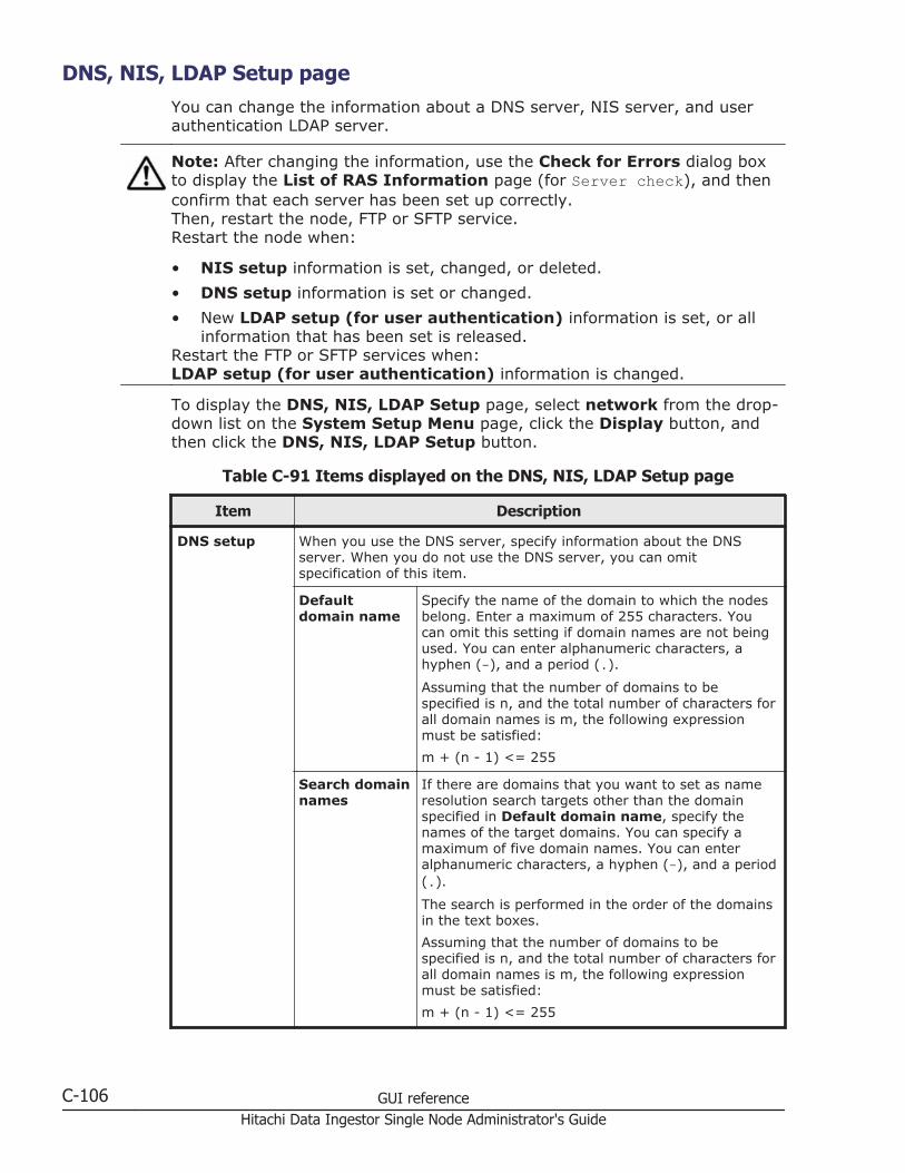
DNS, NIS, LDAP Setup pageYou can change the information about a DNS server, NIS server, and userauthentication LDAP server.
Note: After changing the information, use the Check for Errors dialog boxto display the List of RAS Information page (for Server check), and thenconfirm that each server has been set up correctly.Then, restart the node, FTP or SFTP service.Restart the node when:
• NIS setup information is set, changed, or deleted.
• DNS setup information is set or changed.
• New LDAP setup (for user authentication) information is set, or allinformation that has been set is released.
Restart the FTP or SFTP services when:LDAP setup (for user authentication) information is changed.
To display the DNS, NIS, LDAP Setup page, select network from the drop-down list on the System Setup Menu page, click the Display button, andthen click the DNS, NIS, LDAP Setup button.
Table C-91 Items displayed on the DNS, NIS, LDAP Setup page
Item Description
DNS setup When you use the DNS server, specify information about the DNSserver. When you do not use the DNS server, you can omitspecification of this item.
Defaultdomain name
Specify the name of the domain to which the nodesbelong. Enter a maximum of 255 characters. Youcan omit this setting if domain names are not beingused. You can enter alphanumeric characters, ahyphen (-), and a period (.).
Assuming that the number of domains to bespecified is n, and the total number of characters forall domain names is m, the following expressionmust be satisfied:
m + (n - 1) <= 255
Search domainnames
If there are domains that you want to set as nameresolution search targets other than the domainspecified in Default domain name, specify thenames of the target domains. You can specify amaximum of five domain names. You can enteralphanumeric characters, a hyphen (-), and a period(.).
The search is performed in the order of the domainsin the text boxes.
Assuming that the number of domains to bespecified is n, and the total number of characters forall domain names is m, the following expressionmust be satisfied:
m + (n - 1) <= 255
C-106 GUI referenceHitachi Data Ingestor Single Node Administrator's Guide
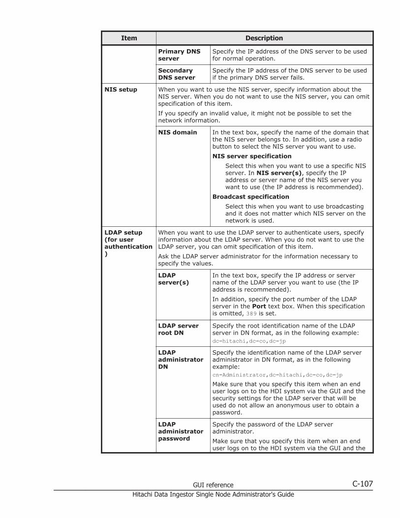
Item Description
Primary DNSserver
Specify the IP address of the DNS server to be usedfor normal operation.
SecondaryDNS server
Specify the IP address of the DNS server to be usedif the primary DNS server fails.
NIS setup When you want to use the NIS server, specify information about theNIS server. When you do not want to use the NIS server, you can omitspecification of this item.
If you specify an invalid value, it might not be possible to set thenetwork information.
NIS domain In the text box, specify the name of the domain thatthe NIS server belongs to. In addition, use a radiobutton to select the NIS server you want to use.
NIS server specification
Select this when you want to use a specific NISserver. In NIS server(s), specify the IPaddress or server name of the NIS server youwant to use (the IP address is recommended).
Broadcast specification
Select this when you want to use broadcastingand it does not matter which NIS server on thenetwork is used.
LDAP setup(for userauthentication)
When you want to use the LDAP server to authenticate users, specifyinformation about the LDAP server. When you do not want to use theLDAP server, you can omit specification of this item.
Ask the LDAP server administrator for the information necessary tospecify the values.
LDAPserver(s)
In the text box, specify the IP address or servername of the LDAP server you want to use (the IPaddress is recommended).
In addition, specify the port number of the LDAPserver in the Port text box. When this specificationis omitted, 389 is set.
LDAP serverroot DN
Specify the root identification name of the LDAPserver in DN format, as in the following example:dc=hitachi,dc=co,dc=jp
LDAPadministratorDN
Specify the identification name of the LDAP serveradministrator in DN format, as in the followingexample:cn=Administrator,dc=hitachi,dc=co,dc=jpMake sure that you specify this item when an enduser logs on to the HDI system via the GUI and thesecurity settings for the LDAP server that will beused do not allow an anonymous user to obtain apassword.
LDAPadministratorpassword
Specify the password of the LDAP serveradministrator.
Make sure that you specify this item when an enduser logs on to the HDI system via the GUI and the
GUI reference C-107Hitachi Data Ingestor Single Node Administrator's Guide

Item Description
security settings for the LDAP server that will beused do not allow an anonymous user to obtain apassword.
List of Routings pageA system administrator can check the routing information in the List ofRoutings page.
To display the List of Routings page, select network from the drop-downlist on the System Setup Menu page, click the Display button, and thenclick the Routing Setup button.
Table C-92 Items displayed on the List of Routings page
Item Description
Protocol version drop-down list
From the drop-down list, select the protocol version whoserouting information you want to check, and then click theDisplay button.
Port drop-down list From the drop-down list, select the port whose routinginformation you want to check, and then click the Displaybutton.
Interface Port The port name
VLAN ID The VLAN ID is displayed if a VLAN is used. A hyphen (-) isdisplayed if a VLAN is not used.
DHCP When IPv4 is used, displays whether DHCP was used in settingthe port routing information.
Target The routing destination. The IP address, host name, or networkname of the target is displayed. If the default route has beenspecified, default is displayed.
Netmask If IPv4 is used, the netmask is displayed for a network. For ahost, a hyphen (-) is displayed. If the default route is set forthe routing destination, 0.0.0.0 is displayed.
Prefix length If IPv6 is used, the prefix length is displayed for a network. Fora host, a hyphen (-) is displayed. If the default route is set forthe routing destination, 0 is displayed.
Gateway The IP address or host name of the gateway through whichnetwork data is routed
Method of specifyingroute
Displays whether a route has been set or denied for therouting target.
AllowA route has been set for the routing target.
RejectA route has been denied for the routing target.
C-108 GUI referenceHitachi Data Ingestor Single Node Administrator's Guide

Item Description
MSS If IPv4 is used, the maximum segment size for the TCPconnection on the route is displayed.
Delete button Click to delete the routing information. Use a radio button toselect the routing information you want to delete, and thenclick this button.
Add button Click to add routing information. The Add Routing page opens(Add Routing page on page C-109).
Add Routing pageA system administrator can add a routing information.
Note:
• Make sure that there are no more than 512 items of routing information.
• Do not add more than one item of routing information for the samedestination. If you do so, the routing information might not be deletedcorrectly.
• Do not set routing information whose settings (except for the gatewaysetting) are the same as those of existing routing information. If you doso, the routing information might not be deleted correctly.
To display the Add Routing page, select network from the drop-down liston the System Setup Menu page, click the Display button, and then clickthe Routing Setup button. Then, from the Protocol version drop-down liston the List of Routings page, select the protocol version for which you wantto add information, and then click the Add button.
Table C-93 Items displayed on the Add Routing page
Item Description
Interface Select the target interface information.
Port
Select the target port from the drop-down list.
VLAN ID
If you select a port using a VLAN for Port, select the targetVLAN ID from the drop-down list. This item is blank if a VLANis not used.
How to specifytarget#1
Select the method to be used to specify the routing destination.
Only one default route can be specified.
Network
Specify the destination by using the network address.
Host
Specify the target by using the host name or IP address.
Default route
GUI reference C-109Hitachi Data Ingestor Single Node Administrator's Guide

Item Description
Specify the default route.
Target#2 Specify the routing destination in the format you selected in Howto specify target. If you select Default route in How tospecify target, default is displayed.
Netmask#1 If IPv4 is used and Network is selected in How to specifytarget, specify the netmask.
If either Host or Default route is selected, you do not need tospecify the netmask. If you specify the netmask, the specificationis ignored.
Prefix length#1 If IPv6 is used and Prefix length is selected in How to specifytarget, specify the prefix length.
If either Host or Default route is selected, you do not need tospecify the prefix length. If you specify the prefix length, thespecification is ignored.
Gateway#2 Enter the IP address or host name of the gateway through whichnetwork data is to be routed.
Method ofspecifying route
Use a radio button to determine whether a route has been set ordenied for the routing setting target.
Allow
Set a route.
Reject
Deny routing.
MSS If IPv4 is used, specify in bytes the maximum segment size forthe TCP connection on the route. Enter a value in the range from64 to 65536.
#1:
• The route added by selecting Network in How to specify target and specifying0.0.0.0 for Netmask or 0 for Prefix length is treated as the default route.
• The routing added by selecting Network in How to specify target and specifying255.255.255.255 for Netmask or 128 for Prefix length works the same as whenthe host is directly specified for the routing destination.
#2:
The IP addresses of the networks listed below cannot be specified as the routingdestination. If specifying one of these is unavoidable, contact the Technical SupportCenter.
• IPv4: 127.0.0.0 to 127.255.255.255• IPv6: "::ffff:IPv4-address", "::IPv4-address", "::1/128", "::/0", "::/128",
"fe80::/10", and "ff00::/8"
• Network whose IP address is set in pm0
Time Setup pageYou can specify time-related information.
C-110 GUI referenceHitachi Data Ingestor Single Node Administrator's Guide
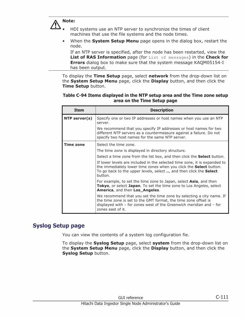
Note:
• HDI systems use an NTP server to synchronize the times of clientmachines that use the file systems and the node times.
• When the System Setup Menu page opens in the dialog box, restart thenode.If an NTP server is specified, after the node has been restarted, view theList of RAS Information page (for List of messages) in the Check forErrors dialog box to make sure that the system message KAQM05154-Ihas been output.
To display the Time Setup page, select network from the drop-down list onthe System Setup Menu page, click the Display button, and then click theTime Setup button.
Table C-94 Items displayed in the NTP setup area and the Time zone setuparea on the Time Setup page
Item Description
NTP server(s) Specify one or two IP addresses or host names when you use an NTPserver.
We recommend that you specify IP addresses or host names for twodifferent NTP servers as a countermeasure against a failure. Do notspecify two host names for the same NTP server.
Time zone Select the time zone.
The time zone is displayed in directory structure.
Select a time zone from the list box, and then click the Select button.
If lower levels are included in the selected time zone, it is expanded tothe immediately lower time zones when you click the Select button.To go back to the upper levels, select .., and then click the Selectbutton.
For example, to set the time zone to Japan, select Asia, and thenTokyo, or select Japan. To set the time zone to Los Angeles, selectAmerica, and then Los_Angeles.
We recommend that you set the time zone by selecting a city name. Ifthe time zone is set to the GMT format, the time zone offset isdisplayed with + for zones west of the Greenwich meridian and - forzones east of it.
Syslog Setup pageYou can view the contents of a system log configuration fie.
To display the Syslog Setup page, select system from the drop-down list onthe System Setup Menu page, click the Display button, and then click theSyslog Setup button.
GUI reference C-111Hitachi Data Ingestor Single Node Administrator's Guide
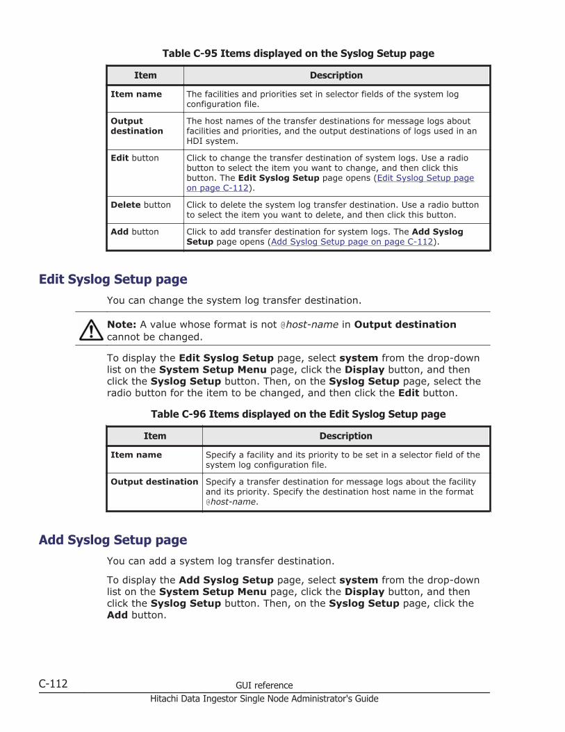
Table C-95 Items displayed on the Syslog Setup page
Item Description
Item name The facilities and priorities set in selector fields of the system logconfiguration file.
Outputdestination
The host names of the transfer destinations for message logs aboutfacilities and priorities, and the output destinations of logs used in anHDI system.
Edit button Click to change the transfer destination of system logs. Use a radiobutton to select the item you want to change, and then click thisbutton. The Edit Syslog Setup page opens (Edit Syslog Setup pageon page C-112).
Delete button Click to delete the system log transfer destination. Use a radio buttonto select the item you want to delete, and then click this button.
Add button Click to add transfer destination for system logs. The Add SyslogSetup page opens (Add Syslog Setup page on page C-112).
Edit Syslog Setup pageYou can change the system log transfer destination.
Note: A value whose format is not @host-name in Output destinationcannot be changed.
To display the Edit Syslog Setup page, select system from the drop-downlist on the System Setup Menu page, click the Display button, and thenclick the Syslog Setup button. Then, on the Syslog Setup page, select theradio button for the item to be changed, and then click the Edit button.
Table C-96 Items displayed on the Edit Syslog Setup page
Item Description
Item name Specify a facility and its priority to be set in a selector field of thesystem log configuration file.
Output destination Specify a transfer destination for message logs about the facilityand its priority. Specify the destination host name in the format@host-name.
Add Syslog Setup pageYou can add a system log transfer destination.
To display the Add Syslog Setup page, select system from the drop-downlist on the System Setup Menu page, click the Display button, and thenclick the Syslog Setup button. Then, on the Syslog Setup page, click theAdd button.
C-112 GUI referenceHitachi Data Ingestor Single Node Administrator's Guide

Table C-97 Items displayed on the Add Syslog Setup page
Item Description
Item name Specify a facility and its priority to be set in a selector field of thesystem log configuration file.
Output destination Specify a transfer destination for message logs about the facilityand its priority. Specify the destination host name in the format@host-name.
Add button Adds a system log transfer destination. Enter the necessaryinformation, and then click this button.
Log File Capacity Setup pageYou can view the number of files saved in a log file and the log file capacity.
Note: Log files that have already been output are not automatically deletedeven if you reduce the number of log files to be saved. If necessary, from theList of RAS Information page, delete the old log files.
To display the Log File Capacity Setup page, select system from the drop-down list on the System Setup Menu page, click the Display button, andthen click the Log File Capacity Setup button.
Table C-98 Items displayed on the Log File Capacity Setup page
Item Description
File type The log file type as a path
Capacity (MB) The capacity at which log files are rotated
Number of files The number of files that can be saved in a log file
Explanation An explanation of the log file
Edit button Click to change the number of files saved in a log file and thecapacity. Use a radio button to select the log file whose settingsyou want to change, and then click this button. The Edit FileCapacity page opens (Edit File Capacity page on page C-113).
Edit File Capacity pageA system administrator can change the maximum number of log files that canbe saved, and the file capacity.
To display the Edit File Capacity page, select system from the drop-downlist on the System Setup Menu page, click the Display button, and thenclick the Log File Capacity Setup button. Then, on the Log File CapacitySetup page, select the radio button for the log file for which you want tochange the settings, and then click the Edit button.
GUI reference C-113Hitachi Data Ingestor Single Node Administrator's Guide
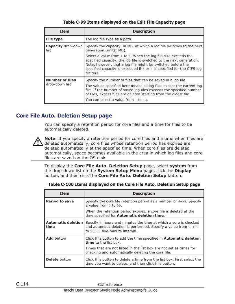
Table C-99 Items displayed on the Edit File Capacity page
Item Description
File type The log file type as a path.
Capacity drop-downlist
Specify the capacity, in MB, at which a log file switches to the nextgeneration (units: MB).
Select a value from 1 to 6. When the log file size exceeds thespecified capacity, the log file is switched to the next generation.Note, however, that a log file might be switched before thespecified capacity is exceeded if 5 or 6 is specified for the CIFS logfile size.
Number of filesdrop-down list
Specify the number of files that can be saved in a log file.
The values specified here means all log files except the current logfile. If the number of saved log files exceeds the specified numberof files, excess files are deleted starting from the oldest file.
You can select a value from 1 to 14.
Core File Auto. Deletion Setup pageYou can specify a retention period for core files and a time for files to beautomatically deleted.
Note: If you specify a retention period for core files and a time when files aredeleted automatically, core files whose retention period has expired aredeleted automatically at the specified time. When core files are deletedautomatically, space becomes available in the area in which log files and corefiles are saved on the OS disk.
To display the Core File Auto. Deletion Setup page, select system fromthe drop-down list on the System Setup Menu page, click the Displaybutton, and then click the Core File Auto. Deletion Setup button.
Table C-100 Items displayed on the Core File Auto. Deletion Setup page
Item Description
Period to save Specify the core file retention period as a number of days. Specifya value from 0 to 99.
When the retention period expires, a core file is deleted at thetime specified for Automatic deletion time.
Automatic deletiontime
Specify in hours and minutes the time at which a core is checkedand automatic deletion is performed. Specify a value from 00:00to 23:55 five-minute interval.
Add button Click this button to add the time specified in Automatic deletiontime to the list box.
Times that are not listed in the list box are not set as times forchecking and automatically deleting the core file.
Delete button Click this button to delete a time from the list box. First select thetime you want to delete, and then click this button.
C-114 GUI referenceHitachi Data Ingestor Single Node Administrator's Guide
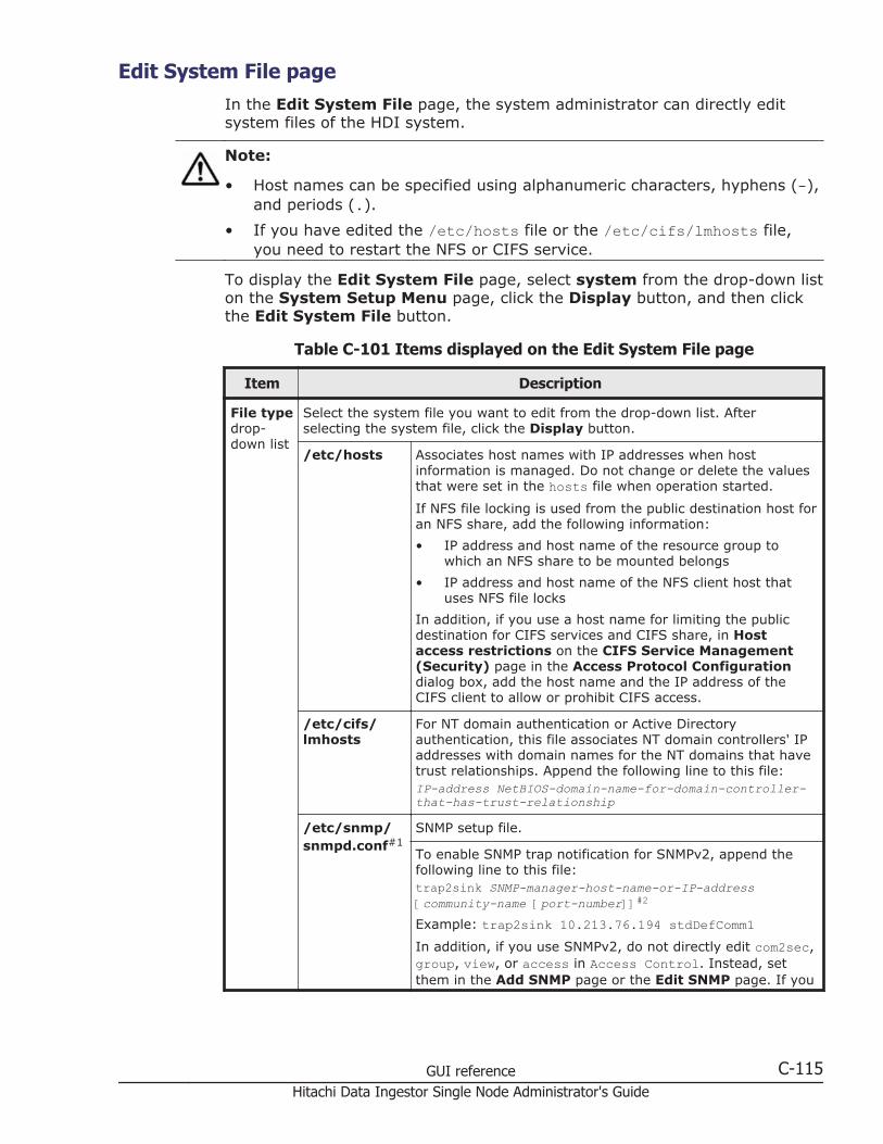
Edit System File pageIn the Edit System File page, the system administrator can directly editsystem files of the HDI system.
Note:
• Host names can be specified using alphanumeric characters, hyphens (-),and periods (.).
• If you have edited the /etc/hosts file or the /etc/cifs/lmhosts file,you need to restart the NFS or CIFS service.
To display the Edit System File page, select system from the drop-down liston the System Setup Menu page, click the Display button, and then clickthe Edit System File button.
Table C-101 Items displayed on the Edit System File page
Item Description
File typedrop-down list
Select the system file you want to edit from the drop-down list. Afterselecting the system file, click the Display button.
/etc/hosts Associates host names with IP addresses when hostinformation is managed. Do not change or delete the valuesthat were set in the hosts file when operation started.
If NFS file locking is used from the public destination host foran NFS share, add the following information:
• IP address and host name of the resource group towhich an NFS share to be mounted belongs
• IP address and host name of the NFS client host thatuses NFS file locks
In addition, if you use a host name for limiting the publicdestination for CIFS services and CIFS share, in Hostaccess restrictions on the CIFS Service Management(Security) page in the Access Protocol Configurationdialog box, add the host name and the IP address of theCIFS client to allow or prohibit CIFS access.
/etc/cifs/lmhosts
For NT domain authentication or Active Directoryauthentication, this file associates NT domain controllers' IPaddresses with domain names for the NT domains that havetrust relationships. Append the following line to this file:IP-address NetBIOS-domain-name-for-domain-controller-that-has-trust-relationship
/etc/snmp/snmpd.conf#1
SNMP setup file.
To enable SNMP trap notification for SNMPv2, append thefollowing line to this file:trap2sink SNMP-manager-host-name-or-IP-address [community-name [port-number]]#2
Example: trap2sink 10.213.76.194 stdDefComm1In addition, if you use SNMPv2, do not directly edit com2sec,group, view, or access in Access Control. Instead, setthem in the Add SNMP page or the Edit SNMP page. If you
GUI reference C-115Hitachi Data Ingestor Single Node Administrator's Guide

Item Description
need to edit them, contact the Hitachi Data SystemsTechnical Support Center.
To use SNMPv3, append the following two lines as SNMPmanagement user information:rouser user-name [security-level [OID]]#3createUser user-name [authentication-type authentication-password [encryption-type encryption-password]]Example:rouser user1 privcreateUser user1 MD5 mypassphrase DES mypasswordFor details about the items to be specified when SNMPv3 isused, see Table 10-1 Information specified in thesnmpd.conf file when SNMPv3 is used on page 10-4.
To enable SNMP trap notification for SNMPv3, append thefollowing line to this file:trapsess -v3 -u user-name [option] SNMP-manager-host-name-or-IP-address[:port-number]#2#4
Example: trapsess -v3 -u user1 -l authPriv -a MD5 -Amypassphrase -x DES -X mypassword 10.213.76.194For details about the items to be specified when SNMPv3 isused, see Table 10-1 Information specified in thesnmpd.conf file when SNMPv3 is used on page 10-4.
To set the file system whose status is acquired and set theunused capacity level of the file system from which an erroris sent, append the following line to the end of the file.disk file-system-path unused-capacityExample of acquiring the status of the fs01 file system andsending an error when the unused capacity goes down to10%: disk /mnt/fs01 10%
For information about file systems, to make a restriction sothat only information related to a specific object is reported,specify the following for each information item:
Specific file system information: fspath file-system-path
Example of reporting the information of the file systemsfs01 and fs02:fspath /mnt/fs01fspath /mnt/fs02
/enas/conf/email_alert.conf
The configuration file for email error notifications. Specifyvalues for the entries in the configuration file as follows:serveraddress=mail-server-fully-qualified-domain-name-or-IPv4-address[:port-number]To use IPv6, specify a fully qualified domain name.
To use a port number other than 25, you must specify theport number.mailtoaddress=email-recipient-addressUp to four addresses can be specified. When specifyingmultiple addresses, separate the addresses with commas(,).
C-116 GUI referenceHitachi Data Ingestor Single Node Administrator's Guide
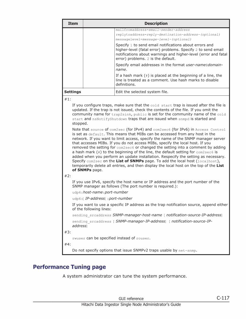
Item Descriptionmailfromaddress=email-sender-addressreplytoaddress=reply-destination-address-(optional)messagelevel=message-level-(optional)Specify 1 to send email notifications about errors andhigher-level (fatal error) problems. Specify 2 to send emailnotifications about warnings and higher-level (error and fatalerror) problems. 2 is the default.
Specify email addresses in the format user-name@domain-name.
If a hash mark (#) is placed at the beginning of a line, theline is treated as a comment. Use hash marks to disabledefinitions.
Settings Edit the selected system file.
#1:
If you configure traps, make sure that the cold start trap is issued after the file isupdated. If the trap is not issued, check the contents of the file. If you omit thecommunity name for trap2sink, public is set for the community name of the coldstart and nsNotifyShutdown traps that are issued when snmpd is started andstopped.
Note that source of com2sec (for IPv4) and com2sec6 (for IPv6) in Access Controlis set as default. This means that MIBs can be accessed from any host in thenetwork. If you want to limit access, specify the name of the SNMP manager serverthat accesses MIBs. If you do not access MIBs, specify the local host. If youremoved the setting for com2sec6 or changed the setting into a comment by addinga hash mark (#) to the beginning of the line, the default setting for com2sec6 isadded when you perform an update installation. Respecify the setting as necessary.Specify com2sec on the List of SNMPs page. To add the local host (localhost),temporarily delete all entries, and then display the local host on the top of the Listof SNMPs page.
#2:
If you use IPv6, specify the host name or IP address and the port number of theSNMP manager as follows (The port number is required.):
udp6:host-name:port-number
udp6:[IP-address]:port-number
If you want to use a specific IP address as the trap notification source, append eitherof the following lines:
sending_srcaddress SNMP-manager-host-name [notification-source-IP-address]sending_srcaddress [SNMP-manager-IP-address] [notification-source-IP-address]
#3:
rwuser can be specified instead of rouser.
#4:
Do not specify options that issue SNMPv2 traps usable by net-snmp.
Performance Tuning pageA system administrator can tune the system performance.
GUI reference C-117Hitachi Data Ingestor Single Node Administrator's Guide
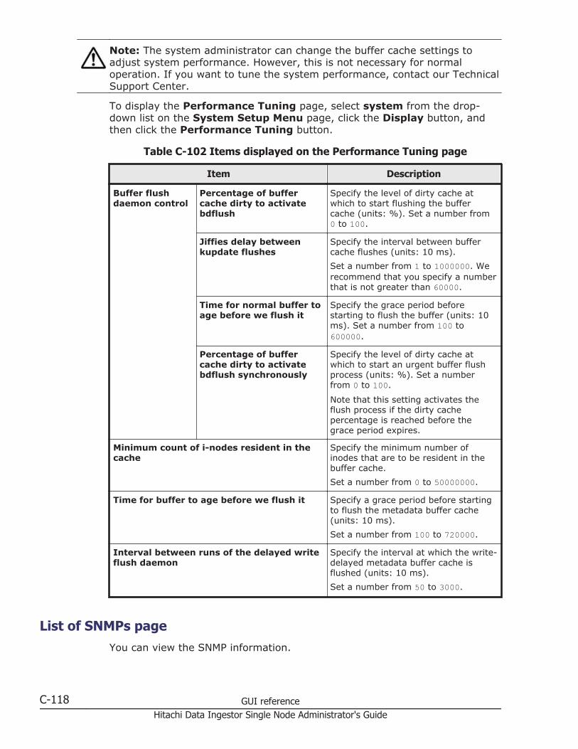
Note: The system administrator can change the buffer cache settings toadjust system performance. However, this is not necessary for normaloperation. If you want to tune the system performance, contact our TechnicalSupport Center.
To display the Performance Tuning page, select system from the drop-down list on the System Setup Menu page, click the Display button, andthen click the Performance Tuning button.
Table C-102 Items displayed on the Performance Tuning page
Item Description
Buffer flushdaemon control
Percentage of buffercache dirty to activatebdflush
Specify the level of dirty cache atwhich to start flushing the buffercache (units: %). Set a number from0 to 100.
Jiffies delay betweenkupdate flushes
Specify the interval between buffercache flushes (units: 10 ms).
Set a number from 1 to 1000000. Werecommend that you specify a numberthat is not greater than 60000.
Time for normal buffer toage before we flush it
Specify the grace period beforestarting to flush the buffer (units: 10ms). Set a number from 100 to600000.
Percentage of buffercache dirty to activatebdflush synchronously
Specify the level of dirty cache atwhich to start an urgent buffer flushprocess (units: %). Set a numberfrom 0 to 100.
Note that this setting activates theflush process if the dirty cachepercentage is reached before thegrace period expires.
Minimum count of i-nodes resident in thecache
Specify the minimum number ofinodes that are to be resident in thebuffer cache.
Set a number from 0 to 50000000.
Time for buffer to age before we flush it Specify a grace period before startingto flush the metadata buffer cache(units: 10 ms).
Set a number from 100 to 720000.
Interval between runs of the delayed writeflush daemon
Specify the interval at which the write-delayed metadata buffer cache isflushed (units: 10 ms).
Set a number from 50 to 3000.
List of SNMPs pageYou can view the SNMP information.
C-118 GUI referenceHitachi Data Ingestor Single Node Administrator's Guide

To display the List of SNMPs page, select system from the drop-down liston the System Setup Menu page, click the Display button, and then clickthe SNMP Setup button.
Table C-103 Items displayed on the List of SNMPs page
Item Description
Source Displays the server name and IP address of the SNMP manager.
Number ofMIB objects
Displays the number of MIB objects.
Edit button Click to edit the SNMP information. Use a radio button to select theSNMP information you want to edit, and then click this button. TheEdit SNMP page opens (Edit SNMP page on page C-119).
Delete button Click to delete the SNMP information. Use a radio button to select theSNMP information you want to delete, and then click this button.
Add button Click to add SNMP information. The Add SNMP page opens (Add SNMPpage on page C-120).
Edit SNMP pageYou can change the SNMP information.
Note:
• If you use SNMP trap notification with SNMPv2, use SNMPv3, or use SNMPin an IPv6 environment, you need to edit the snmpd.conf file.
• If you use the SNMP trap notification, we recommend that yousynchronize the time of the SNMP manager and the OS. If the timesdiffer, the time of the SNMP manager is used for the receiving time ofSNMP traps.
To display the Edit SNMP page, select system from the drop-down list onthe System Setup Menu page, click the Display button, and then click theSNMP Setup button. Then, on the List of SNMPs page, select the radiobutton for the SNMP information you want to change, and then click the Editbutton.
Table C-104 Items displayed on the Edit SNMP page
Item Description
Source Specify the server name and IP address of the SNMP manager.
The specified source SNMP manager can view and acquire informationfrom the MIB object.
Community Specify a community name.
The SNMP manager uses the community name to access the MIB valueof an SNMP agent.
MIB objects Specify the MIB object name, the mask, and the specification method.
GUI reference C-119Hitachi Data Ingestor Single Node Administrator's Guide
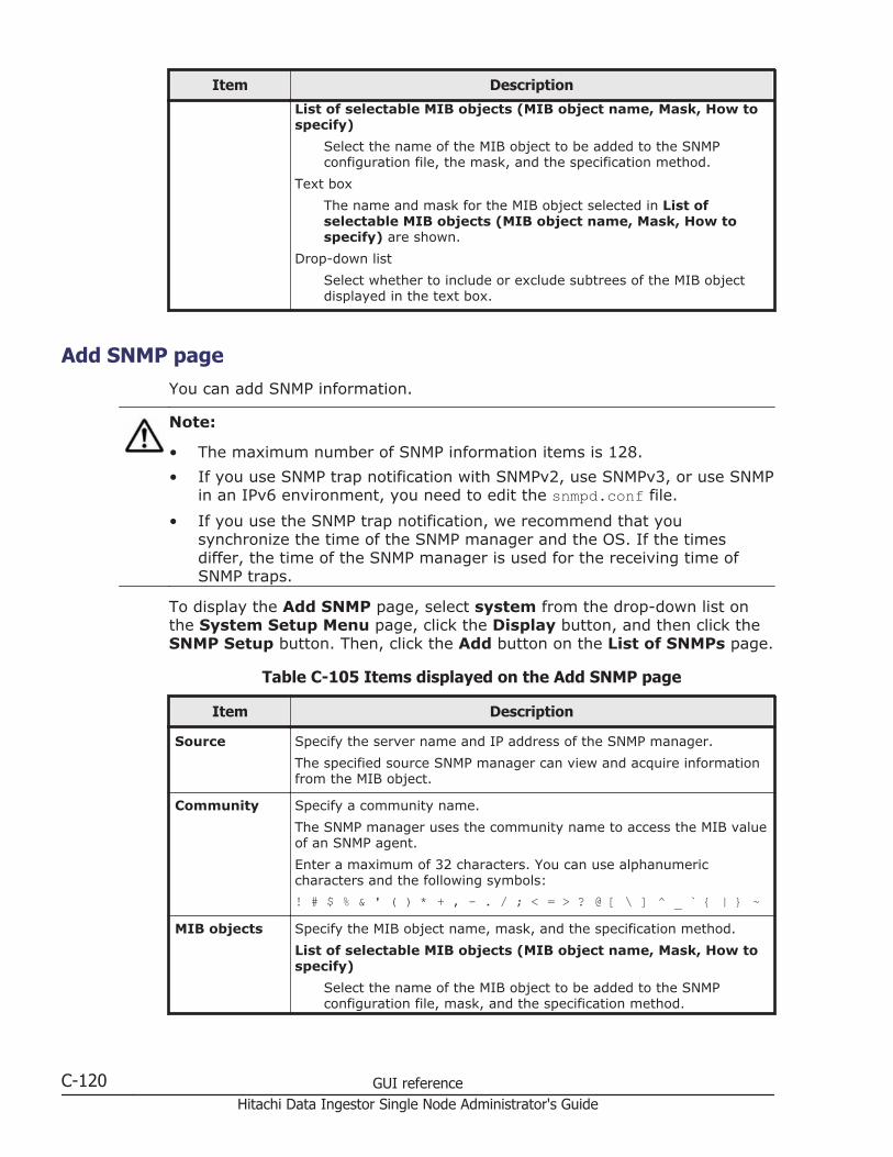
Item Description
List of selectable MIB objects (MIB object name, Mask, How tospecify)
Select the name of the MIB object to be added to the SNMPconfiguration file, the mask, and the specification method.
Text box
The name and mask for the MIB object selected in List ofselectable MIB objects (MIB object name, Mask, How tospecify) are shown.
Drop-down list
Select whether to include or exclude subtrees of the MIB objectdisplayed in the text box.
Add SNMP pageYou can add SNMP information.
Note:
• The maximum number of SNMP information items is 128.
• If you use SNMP trap notification with SNMPv2, use SNMPv3, or use SNMPin an IPv6 environment, you need to edit the snmpd.conf file.
• If you use the SNMP trap notification, we recommend that yousynchronize the time of the SNMP manager and the OS. If the timesdiffer, the time of the SNMP manager is used for the receiving time ofSNMP traps.
To display the Add SNMP page, select system from the drop-down list onthe System Setup Menu page, click the Display button, and then click theSNMP Setup button. Then, click the Add button on the List of SNMPs page.
Table C-105 Items displayed on the Add SNMP page
Item Description
Source Specify the server name and IP address of the SNMP manager.
The specified source SNMP manager can view and acquire informationfrom the MIB object.
Community Specify a community name.
The SNMP manager uses the community name to access the MIB valueof an SNMP agent.
Enter a maximum of 32 characters. You can use alphanumericcharacters and the following symbols:
! # $ % & ' ( ) * + , - . / ; < = > ? @ [ \ ] ^ _ ` { | } ~
MIB objects Specify the MIB object name, mask, and the specification method.
List of selectable MIB objects (MIB object name, Mask, How tospecify)
Select the name of the MIB object to be added to the SNMPconfiguration file, mask, and the specification method.
C-120 GUI referenceHitachi Data Ingestor Single Node Administrator's Guide

Item Description
Text box
The name and mask for the MIB object selected in List ofselectable MIB objects (MIB object name, Mask, How tospecify) are shown.
Drop-down list
Select whether to include or exclude subtrees of the MIB objectdisplayed in the text box. When you want to include subtrees ofthe MIB object name, select Include. Otherwise, select Do notinclude.
Click the Select button to add the MIB object to Selected MIBobjects. Only the MIB objects displayed in Selected MIBobjects can be set as the SNMP information. When you want todelete an MIB object from Selected MIB objects, select the MIBobject and click the Delete button.
Access Protocol Configuration dialog boxYou can perform operations such as changing the client authenticationmethod.
To display the Access Protocol Configuration dialog box, click AccessProtocol Configuration in the Settings area of the host-name window.
List of Services pageYou can set up CIFS, NFS, FTP, and SFTP services.
The List of Services page first appears after the Access ProtocolConfiguration dialog box is displayed.
Table C-106 Items displayed on the List of Services page
Item Description
Service name Displays the service name.
CIFSDisplayed when the service is a CIFS service.
FTPDisplayed when the service is an FTP service.
NFSDisplayed when the service is an NFS service.
SFTPDisplayed when the service is an SFTP service.
SSHDisplayed when the service is an SSH service.
Status Displays the operating status of the service.
Running
GUI reference C-121Hitachi Data Ingestor Single Node Administrator's Guide
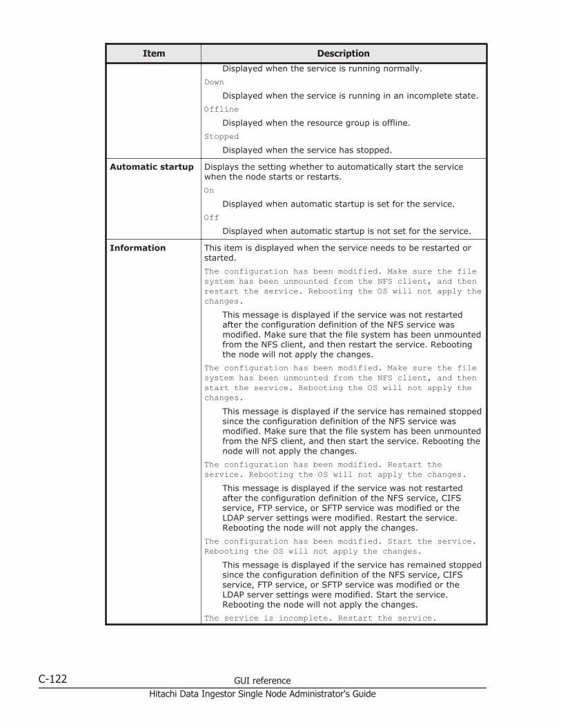
Item Description
Displayed when the service is running normally.
DownDisplayed when the service is running in an incomplete state.
OfflineDisplayed when the resource group is offline.
StoppedDisplayed when the service has stopped.
Automatic startup Displays the setting whether to automatically start the servicewhen the node starts or restarts.
OnDisplayed when automatic startup is set for the service.
OffDisplayed when automatic startup is not set for the service.
Information This item is displayed when the service needs to be restarted orstarted.
The configuration has been modified. Make sure the filesystem has been unmounted from the NFS client, and thenrestart the service. Rebooting the OS will not apply thechanges.
This message is displayed if the service was not restartedafter the configuration definition of the NFS service wasmodified. Make sure that the file system has been unmountedfrom the NFS client, and then restart the service. Rebootingthe node will not apply the changes.
The configuration has been modified. Make sure the filesystem has been unmounted from the NFS client, and thenstart the service. Rebooting the OS will not apply thechanges.
This message is displayed if the service has remained stoppedsince the configuration definition of the NFS service wasmodified. Make sure that the file system has been unmountedfrom the NFS client, and then start the service. Rebooting thenode will not apply the changes.
The configuration has been modified. Restart theservice. Rebooting the OS will not apply the changes.
This message is displayed if the service was not restartedafter the configuration definition of the NFS service, CIFSservice, FTP service, or SFTP service was modified or theLDAP server settings were modified. Restart the service.Rebooting the node will not apply the changes.
The configuration has been modified. Start the service.Rebooting the OS will not apply the changes.
This message is displayed if the service has remained stoppedsince the configuration definition of the NFS service, CIFSservice, FTP service, or SFTP service was modified or theLDAP server settings were modified. Start the service.Rebooting the node will not apply the changes.
The service is incomplete. Restart the service.
C-122 GUI referenceHitachi Data Ingestor Single Node Administrator's Guide
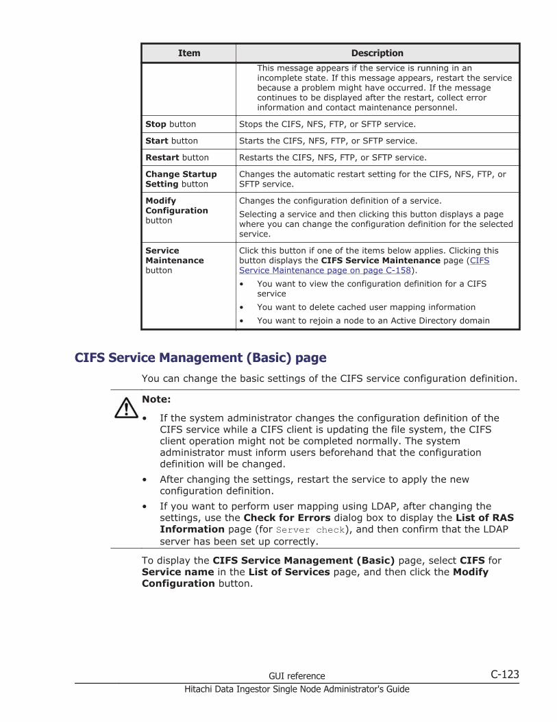
Item Description
This message appears if the service is running in anincomplete state. If this message appears, restart the servicebecause a problem might have occurred. If the messagecontinues to be displayed after the restart, collect errorinformation and contact maintenance personnel.
Stop button Stops the CIFS, NFS, FTP, or SFTP service.
Start button Starts the CIFS, NFS, FTP, or SFTP service.
Restart button Restarts the CIFS, NFS, FTP, or SFTP service.
Change StartupSetting button
Changes the automatic restart setting for the CIFS, NFS, FTP, orSFTP service.
ModifyConfigurationbutton
Changes the configuration definition of a service.
Selecting a service and then clicking this button displays a pagewhere you can change the configuration definition for the selectedservice.
ServiceMaintenancebutton
Click this button if one of the items below applies. Clicking thisbutton displays the CIFS Service Maintenance page (CIFSService Maintenance page on page C-158).
• You want to view the configuration definition for a CIFSservice
• You want to delete cached user mapping information
• You want to rejoin a node to an Active Directory domain
CIFS Service Management (Basic) pageYou can change the basic settings of the CIFS service configuration definition.
Note:
• If the system administrator changes the configuration definition of theCIFS service while a CIFS client is updating the file system, the CIFSclient operation might not be completed normally. The systemadministrator must inform users beforehand that the configurationdefinition will be changed.
• After changing the settings, restart the service to apply the newconfiguration definition.
• If you want to perform user mapping using LDAP, after changing thesettings, use the Check for Errors dialog box to display the List of RASInformation page (for Server check), and then confirm that the LDAPserver has been set up correctly.
To display the CIFS Service Management (Basic) page, select CIFS forService name in the List of Services page, and then click the ModifyConfiguration button.
GUI reference C-123Hitachi Data Ingestor Single Node Administrator's Guide
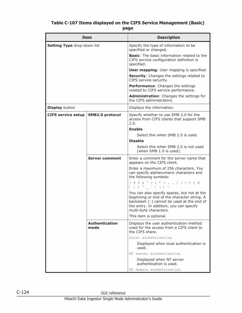
Table C-107 Items displayed on the CIFS Service Management (Basic)page
Item Description
Setting Type drop-down list Specify the type of information to bespecified or changed.
Basic: The basic information related to theCIFS service configuration definition isspecified.
User mapping: User mapping is specified.
Security: Changes the settings related toCIFS service security.
Performance: Changes the settingsrelated to CIFS service performance.
Administration: Changes the settings forthe CIFS administrators.
Display button Displays the information.
CIFS service setup SMB2.0 protocol Specify whether to use SMB 2.0 for theaccess from CIFS clients that support SMB2.0.
Enable
Select this when SMB 2.0 is used.
Disable
Select this when SMB 2.0 is not used(when SMB 1.0 is used).
Server comment Enter a comment for the server name thatappears on the CIFS client.
Enter a maximum of 256 characters. Youcan specify alphanumeric characters andthe following symbols:
! # $ & ' ( ) * + , . / : < > ? @[ \ ] ^ _ ` { | } ~You can also specify spaces, but not at thebeginning or end of the character string. Abackslash (\) cannot be used at the end ofthe entry. In addition, you can specifymulti-byte characters.
This item is optional.
Authenticationmode
Displays the user authentication methodused for the access from a CIFS client tothe CIFS share.
Local authenticationDisplayed when local authentication isused.
NT server authenticationDisplayed when NT serverauthentication is used.
NT domain authentication
C-124 GUI referenceHitachi Data Ingestor Single Node Administrator's Guide
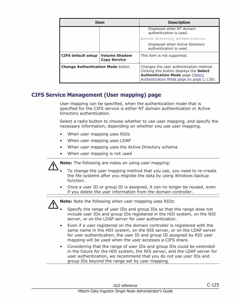
Item Description
Displayed when NT domainauthentication is used.
Active Directory authenticationDisplayed when Active Directoryauthentication is used.
CIFS default setup Volume ShadowCopy Service
This item is not supported.
Change Authentication Mode button Changes the user authentication method.Clicking this button displays the SelectAuthentication Mode page (SelectAuthentication Mode page on page C-138).
CIFS Service Management (User mapping) pageUser mapping can be specified, when the authentication mode that isspecified for the CIFS service is either NT domain authentication or ActiveDirectory authentication.
Select a radio button to choose whether to use user mapping, and specify thenecessary information, depending on whether you use user mapping.
• When user mapping uses RIDs
• When user mapping uses LDAP
• When user mapping uses the Active Directory schema
• When user mapping is not used
Note: The following are notes on using user mapping:
• To change the user mapping method that you use, you need to re-createthe file systems after you migrate the data by using Windows backupfunction.
• Once a user ID or group ID is assigned, it can no longer be reused, evenif you delete the user information from the domain controller.
Note: Note the following when user mapping uses RIDs:
• Specify the range of user IDs and group IDs so that the range does notinclude user IDs and group IDs registered in the HDI system, on the NISserver, or on the LDAP server for user authentication.
• Even if a user registered on the domain controller is registered with thesame name in the HDI system, on the NIS server, or on the LDAP serverfor user authentication, the user ID and group ID assigned by RID usermapping will be used when the user accesses a CIFS share.
• Considering that the range of user IDs and group IDs could be extendedin the future for the HDI system, the NIS server, and the LDAP server foruser authentication, we recommend that you do not use user IDs andgroup IDs beyond the range set by user mapping.
GUI reference C-125Hitachi Data Ingestor Single Node Administrator's Guide
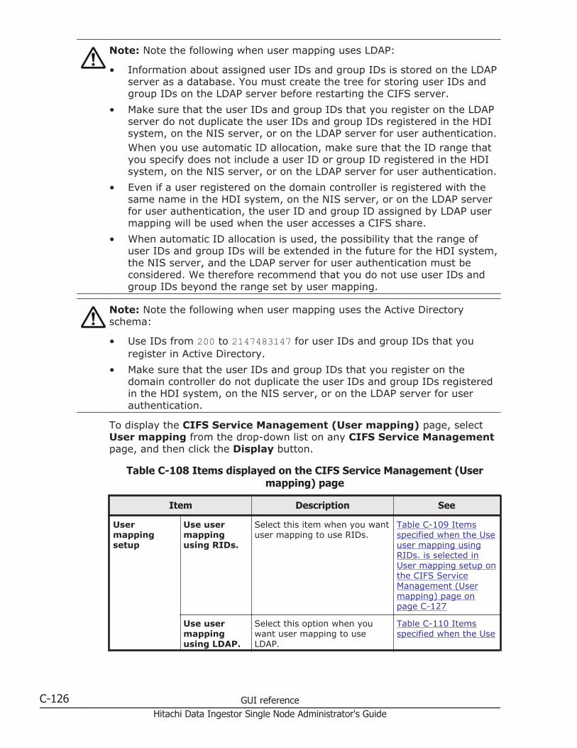
Note: Note the following when user mapping uses LDAP:
• Information about assigned user IDs and group IDs is stored on the LDAPserver as a database. You must create the tree for storing user IDs andgroup IDs on the LDAP server before restarting the CIFS server.
• Make sure that the user IDs and group IDs that you register on the LDAPserver do not duplicate the user IDs and group IDs registered in the HDIsystem, on the NIS server, or on the LDAP server for user authentication.When you use automatic ID allocation, make sure that the ID range thatyou specify does not include a user ID or group ID registered in the HDIsystem, on the NIS server, or on the LDAP server for user authentication.
• Even if a user registered on the domain controller is registered with thesame name in the HDI system, on the NIS server, or on the LDAP serverfor user authentication, the user ID and group ID assigned by LDAP usermapping will be used when the user accesses a CIFS share.
• When automatic ID allocation is used, the possibility that the range ofuser IDs and group IDs will be extended in the future for the HDI system,the NIS server, and the LDAP server for user authentication must beconsidered. We therefore recommend that you do not use user IDs andgroup IDs beyond the range set by user mapping.
Note: Note the following when user mapping uses the Active Directoryschema:
• Use IDs from 200 to 2147483147 for user IDs and group IDs that youregister in Active Directory.
• Make sure that the user IDs and group IDs that you register on thedomain controller do not duplicate the user IDs and group IDs registeredin the HDI system, on the NIS server, or on the LDAP server for userauthentication.
To display the CIFS Service Management (User mapping) page, selectUser mapping from the drop-down list on any CIFS Service Managementpage, and then click the Display button.
Table C-108 Items displayed on the CIFS Service Management (Usermapping) page
Item Description See
Usermappingsetup
Use usermappingusing RIDs.
Select this item when you wantuser mapping to use RIDs.
Table C-109 Itemsspecified when the Useuser mapping usingRIDs. is selected inUser mapping setup onthe CIFS ServiceManagement (Usermapping) page onpage C-127
Use usermappingusing LDAP.
Select this option when youwant user mapping to useLDAP.
Table C-110 Itemsspecified when the Use
C-126 GUI referenceHitachi Data Ingestor Single Node Administrator's Guide
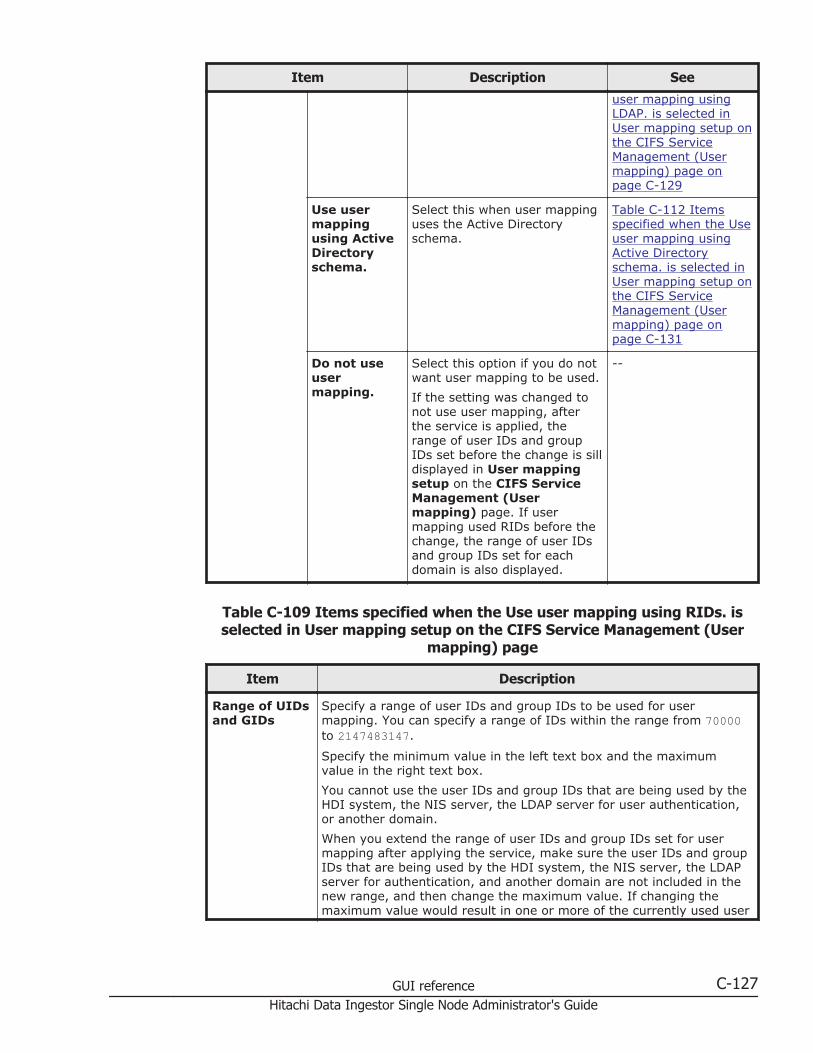
Item Description See
user mapping usingLDAP. is selected inUser mapping setup onthe CIFS ServiceManagement (Usermapping) page onpage C-129
Use usermappingusing ActiveDirectoryschema.
Select this when user mappinguses the Active Directoryschema.
Table C-112 Itemsspecified when the Useuser mapping usingActive Directoryschema. is selected inUser mapping setup onthe CIFS ServiceManagement (Usermapping) page onpage C-131
Do not useusermapping.
Select this option if you do notwant user mapping to be used.
If the setting was changed tonot use user mapping, afterthe service is applied, therange of user IDs and groupIDs set before the change is silldisplayed in User mappingsetup on the CIFS ServiceManagement (Usermapping) page. If usermapping used RIDs before thechange, the range of user IDsand group IDs set for eachdomain is also displayed.
--
Table C-109 Items specified when the Use user mapping using RIDs. isselected in User mapping setup on the CIFS Service Management (User
mapping) page
Item Description
Range of UIDsand GIDs
Specify a range of user IDs and group IDs to be used for usermapping. You can specify a range of IDs within the range from 70000to 2147483147.
Specify the minimum value in the left text box and the maximumvalue in the right text box.
You cannot use the user IDs and group IDs that are being used by theHDI system, the NIS server, the LDAP server for user authentication,or another domain.
When you extend the range of user IDs and group IDs set for usermapping after applying the service, make sure the user IDs and groupIDs that are being used by the HDI system, the NIS server, the LDAPserver for authentication, and another domain are not included in thenew range, and then change the maximum value. If changing themaximum value would result in one or more of the currently used user
GUI reference C-127Hitachi Data Ingestor Single Node Administrator's Guide

Item Description
IDs or group IDs being included in the new range, you need to re-create the file system, and then change the minimum value to extendthe range.
Set an adequate range of user IDs and group IDs after consideringhow long the operation will be performed and how much the number ofusers will increase.
Settings foreach domain
Specify a range of user IDs and group IDs for each domain. You canspecify a range for a maximum of 256 domains. Register no more than20 domains each time. If more than 20 domains are registered at thesame time, a timeout might occur.
Domain name (NetBIOS)
Specify a domain name. Specify the name of a domain that has atrust relationship with the domain to be used for the userauthentication method.
Range of UIDs and GIDs
Specify a range of user IDs and group IDs for the specifieddomain. You can specify this range within the range of user IDsand group IDs set by user mapping.
Specify the minimum value in the left text box and the maximumvalue in the right text box. Make sure that the range for a domaindoes not overlap the range of another domain. The ranges fordomains do not need to be consecutive.
After specifying the name of a domain and the range of user IDsand group IDs for the domain, when you click the Set button, thespecified information is added to a list box. To remove an entryfrom the list box, select the entry and then click the Deletebutton. The entries in the list box are sorted in ascending orderbased on the ID range minimum value of each domain.
You cannot use the user IDs and group IDs that are being used bythe HDI system, the NIS server, the LDAP server for userauthentication, or another domain.
When you extend the range of user IDs and group IDs set for usermapping after applying the service, make sure the user IDs andgroup IDs that are being used by the HDI system, the LDAP serverfor authentication, the NIS server, and another domain are notincluded in the new range, and then change the maximum value.If changing the maximum value would result in one or more of thecurrently used user IDs or group IDs being included in the newrange, you need to re-create the file system, and then change theminimum value to extend the range.
Set an adequate range of user IDs and group IDs after consideringhow long the operation will be performed and how much thenumber of users will increase.
C-128 GUI referenceHitachi Data Ingestor Single Node Administrator's Guide
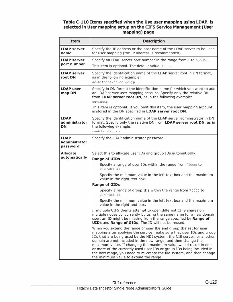
Table C-110 Items specified when the Use user mapping using LDAP. isselected in User mapping setup on the CIFS Service Management (User
mapping) page
Item Description
LDAP servername
Specify the IP address or the host name of the LDAP server to be usedfor user mapping (the IP address is recommended).
LDAP serverport number
Specify an LDAP server port number in the range from 1 to 65535.
This item is optional. The default value is 389.
LDAP serverroot DN
Specify the identification name of the LDAP server root in DN format,as in the following example:dc=hitachi,dc=co,dc=jp
LDAP usermap DN
Specify in DN format the identification name for which you want to addan LDAP server user mapping account. Specify only the relative DNfrom LDAP server root DN, as in the following example:ou=idmapThis item is optional. If you omit this item, the user mapping accountis stored in the DN specified in LDAP server root DN.
LDAPadministratorDN
Specify the identification name of the LDAP server administrator in DNformat. Specify only the relative DN from LDAP server root DN, as inthe following example:cn=Administrator
LDAPadministratorpassword
Specify the LDAP administrator password.
Allocateautomatically
Select this to allocate user IDs and group IDs automatically.
Range of UIDs
Specify a range of user IDs within the range from 70000 to2147483147.
Specify the minimum value in the left text box and the maximumvalue in the right text box.
Range of GIDs
Specify a range of group IDs within the range from 70000 to2147483147.
Specify the minimum value in the left text box and the maximumvalue in the right text box.
If multiple CIFS clients attempt to open different CIFS shares onmultiple nodes concurrently by using the same name for a new domainuser, an ID might be missing from the range specified by Range ofUIDs and Range of GIDs. The ID will not be reused.
When you extend the range of user IDs and group IDs set for usermapping after applying the service, make sure that user IDs and groupIDs that are being used by the HDI system, the NIS server, or anotherdomain are not included in the new range, and then change themaximum value. If changing the maximum value would result in oneor more of the currently used user IDs or group IDs being included inthe new range, you need to re-create the file system, and then changethe minimum value to extend the range.
GUI reference C-129Hitachi Data Ingestor Single Node Administrator's Guide

Item Description
If you change the minimum value of a previously set user ID or groupID, you need to perform additional tasks such as re-creating the LDAPserver. Set an adequate range of user IDs and group IDs afterconsidering how long the operation will be performed and how muchthe number of users will increase.
When user mapping uses LDAP and assigns IDs automatically, you cancheck the largest value of the assigned user IDs and group IDs in Usermapping ID assignment information on the CIFS ServiceManagement (User mapping) page.
Allocatemanually
Select this to allocate user IDs and group IDs manually.
Use IDs from 200 to 2147483147 for user IDs and group IDs that youregister on the LDAP server.
In Table C-111 Items displayed in the User mapping ID assignmentinformation on the CIFS Service Management (User mapping) page onpage C-130, you can check the largest ID within the range of user IDsand group IDs that have already been assigned in the HDI system.
Table C-111 Items displayed in the User mapping ID assignmentinformation on the CIFS Service Management (User mapping) page
Item Description
Largestcurrently usedUID
Displays the largest user ID within the range of user IDs that havealready been assigned in the HDI system. Depending on the status ofuser mapping usage, the following information might be displayed:
-Displayed when user mapping is not used.
Not used, or less than the minimum UID used.Displayed when no user IDs have been assigned, or the smallestassigned user ID is smaller than the minimum value set in Rangeof UIDs.
Cannot be got from LDAP server. Check the LDAP serversettings and CIFS service configuration in service.
Displayed when the largest user ID could not be acquired from theLDAP server for user mapping. Check the user mapping settingsand the operating status of the LDAP server.
Largestcurrently usedGID
Displays the largest group ID within the range of group IDs that havealready been assigned in the HDI system. Depending on the status ofuser mapping usage, the following information might be displayed:
-Displayed when user mapping is not used.
Not used, or less than the minimum GID used.Displayed when no group IDs have been assigned, or the smallestassigned group ID is smaller than the minimum value set inRange of GIDs.
Cannot be got from LDAP server. Check the LDAP serversettings and CIFS service configuration in service.
C-130 GUI referenceHitachi Data Ingestor Single Node Administrator's Guide

Item Description
Displayed when the largest group ID could not be acquired fromthe LDAP server for user mapping. Check the user mappingsettings and the operating status of the LDAP server.
Table C-112 Items specified when the Use user mapping using ActiveDirectory schema. is selected in User mapping setup on the CIFS Service
Management (User mapping) page
Item Description
Name serviceswitch
Select the name service switch. If you are using Windows Server 2003R2 or later, select Using LDAP as a network information service(RFC2307).
Microsoft® Services for Unix
Select this to use Microsoft services for Unix to obtain user IDsand group IDs from the domain controller.
Using LDAP as a network information service (RFC2307)
Select this to use the RFC2307 schema to obtain user IDs andgroup IDs from the domain controller.
Joined domainname
Displays the name of the domain to which nodes belong.
Trusteddomain name
Displays the name of a domain that has a confidential relationship withthe domain to which nodes belong. If there is no domain that has aconfidential relationship, - is displayed.
Note: Use IDs from 200 to 2147483147 for user IDs and group IDs that you register inActive Directory.
If Domain controller: LDAP server signing requirements of the domain controllerpolicy is Require signing, startup of the CIFS services will fail. Therefore, select None.
Depending on the authentication server OS, the procedure for checking the domaincontroller policy differs slightly.
For Windows Server 2003:
Choose Administrative Tools and then Domain Controller Security Policy. Inthe window that appears, choose Security Settings, Local Policies, and thenSecurity Options, and then check whether Domain controller: LDAP serversigning requirements is specified.
For Windows Server 2008 or Windows Server 2012:
Choose Administrative Tools, Group Policy Management Editor, ComputerConfiguration, Policies, Windows Settings, and then Security Settings. In thewindow that appears, choose Local Policies and then Security Options, and thencheck whether Domain controller: LDAP server signing requirements isspecified.
CIFS Service Management (Security) pageYou can change the CIFS service security settings.
Note:
GUI reference C-131Hitachi Data Ingestor Single Node Administrator's Guide
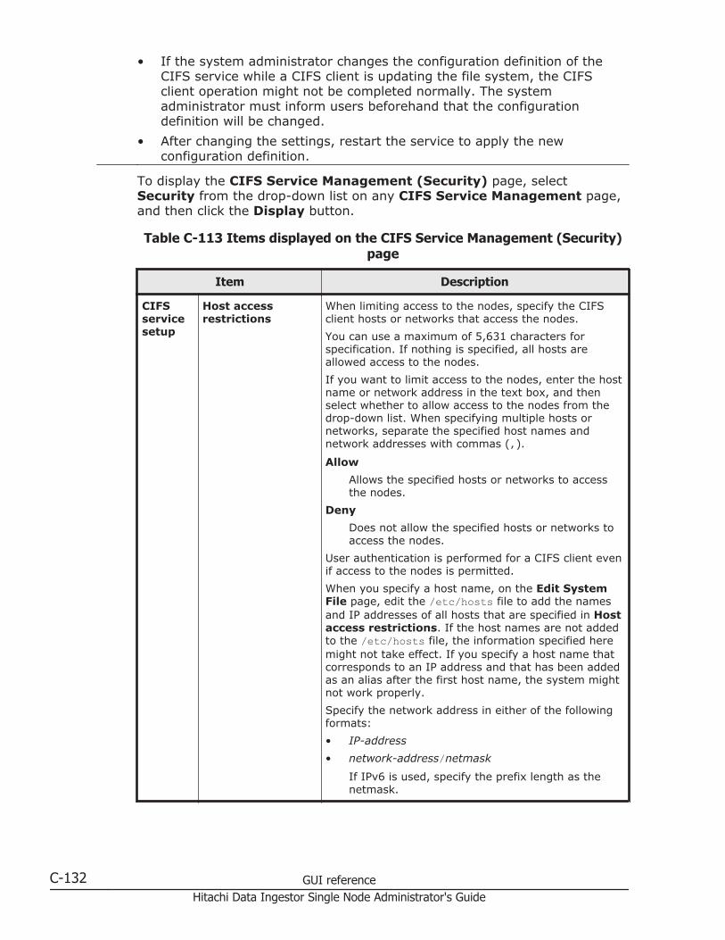
• If the system administrator changes the configuration definition of theCIFS service while a CIFS client is updating the file system, the CIFSclient operation might not be completed normally. The systemadministrator must inform users beforehand that the configurationdefinition will be changed.
• After changing the settings, restart the service to apply the newconfiguration definition.
To display the CIFS Service Management (Security) page, selectSecurity from the drop-down list on any CIFS Service Management page,and then click the Display button.
Table C-113 Items displayed on the CIFS Service Management (Security)page
Item Description
CIFSservicesetup
Host accessrestrictions
When limiting access to the nodes, specify the CIFSclient hosts or networks that access the nodes.
You can use a maximum of 5,631 characters forspecification. If nothing is specified, all hosts areallowed access to the nodes.
If you want to limit access to the nodes, enter the hostname or network address in the text box, and thenselect whether to allow access to the nodes from thedrop-down list. When specifying multiple hosts ornetworks, separate the specified host names andnetwork addresses with commas (,).
Allow
Allows the specified hosts or networks to accessthe nodes.
Deny
Does not allow the specified hosts or networks toaccess the nodes.
User authentication is performed for a CIFS client evenif access to the nodes is permitted.
When you specify a host name, on the Edit SystemFile page, edit the /etc/hosts file to add the namesand IP addresses of all hosts that are specified in Hostaccess restrictions. If the host names are not addedto the /etc/hosts file, the information specified heremight not take effect. If you specify a host name thatcorresponds to an IP address and that has been addedas an alias after the first host name, the system mightnot work properly.
Specify the network address in either of the followingformats:
• IP-address
• network-address/netmask
If IPv6 is used, specify the prefix length as thenetmask.
C-132 GUI referenceHitachi Data Ingestor Single Node Administrator's Guide

Item Description
Mapping to guestaccount
Specify the definition of guest account users.
If the authentication mode is NT server authentication,only Never can be specified.
Unregistered users
Select this if users unregistered in the system canbe guest account users.
Unregistered users or invalid passwords
Select this if users unregistered in the system orusers registered in the system who use anincorrect password can be guest account users.
Note that if Unregistered users or invalidpasswords is selected, users registered in thesystem can be guest account users even if theusers enter an incorrect password.
Never
Select this to deny access by guest account usersto the CIFS shares.
The guest account is regarded as nobody (user ID:65534). Therefore, allow access permissions in theCIFS share that guest account users can access asnobody. You cannot set an ACL that specifies a guestaccount.
The users unregistered in the system differ dependingon the user authentication mode being used, as shownbelow.
• When Local authentication is being used
The users not registered in the HDI system
• When NT server authentication is being used
The users not registered in the Windows NT server
• When NT domain authentication is being used
The users not registered in the domain controllerin the domain
• When Active Directory authentication is being used
The users not registered in the Active Directorydomain controller
NetBIOS overTCP/IP
Specify whether to accept access from CIFS clientsthat uses NetBIOS over TCP/IP.
Use
Select this if you want the CIFS service to acceptaccess from CIFS clients that uses NetBIOS overTCP/IP.
If Use is selected, name resolution that usesWINS, lmhosts, or broadcast, and the browsingfunction are available. When using the browsingfunction for CIFS shares, configure the networkrequired to use CIFS shares as described in theInstallation and Configuration Guide.
Do not use
GUI reference C-133Hitachi Data Ingestor Single Node Administrator's Guide

Item Description
Select this if you do not want the CIFS service toaccept access from CIFS clients that uses NetBIOSover TCP/IP.
If Do not use is selected, data communicationload and security risks can be reduced. However,note the following when you select this:
- The available name resolution service is DNS orhosts. The browsing function is not available.
- Users cannot access the CIFS share from CIFSclients on which Windows NT is running.
CIFS access log Specify whether to collect CIFS access log data.
Use
Select this if you want to collect CIFS access logdata.
Select If the CIFS access log file exceeds themax. size, do not collect log data. if the log filecannot be moved (when the move destination isnot specified, or when the capacity of the filesystem to which the log file is to be moved hasreached the maximum limit), and if you want tostop collecting CIFS access log data when thecapacity of the log file reaches the maximum limit.You can select If the CIFS access log fileexceeds the max. size, do not collect logdata. only when Use is selected.
Do not use
Select this if you do not want to collect CIFSaccess log data.
CIFSdefaultsetup
Guest accountaccess
For CIFS shares, specify access permissions for guestaccount users.
Allow
Select this to allow guest account users access tothe CIFS service.
Disallow
Select this to disallow guest account users accessto the CIFS service.
The guest account is regarded as nobody (user ID:65534). Therefore, allow access permissions in theCIFS share that guest account users can access asnobody. You cannot set an ACL that specifies a guestaccount.
Access BasedEnumeration
Specify whether to use access-based enumeration.
Use
Select this to use access-based enumeration.
Do not use
Select this to not use access-based enumeration.
C-134 GUI referenceHitachi Data Ingestor Single Node Administrator's Guide

Item Description
File timestampchangeable users
Select the users for whom you want to allow updatingof CIFS share file timestamps. Select Writepermitted users if the file is shared by the CIFSservice only.
Write permitted users
Select this if you want to permit updating of theCIFS share file timestamp for all users who arepermitted to write to this file.
Owner only
Select this if you want to restrict timestampupdating to the file owner.
Note that this setting is invalid in an advanced ACL filesystem.
Events logged tothe CIFS accesslog
Specify the trigger conditions for collecting CIFS accesslog information. This setting is enabled only when Useis selected in CIFS access log.
Clicking the Set Up button displays the SettingEvents Logged to the CIFS Access Log page(Setting Events Logged to the CIFS Access Log pageon page C-144).
CIFS Service Management (Performance) pageYou can change the CIFS service performance settings.
Note:
• If the system administrator changes the configuration definition of theCIFS service while a CIFS client is updating the file system, the CIFSclient operation might not be completed normally. The systemadministrator must inform users beforehand that the configurationdefinition will be changed.
• After changing the settings, restart the service to apply the newconfiguration definition.
To display the CIFS Service Management (Performance) page, selectPerformance from the drop-down list on any CIFS Service Managementpage, and then click the Display button.
Table C-114 Items displayed on the CIFS Service Management(Performance) page
Item Description
CIFSservicesetup
Client time-out Specify in minutes the maximum time to wait for aCIFS client response as the timeout value.
Specify a value from 0 to 1440.
When 0 is specified, a client is not automaticallydisconnected by a timeout. If the specified value issmaller than the default, you might not be able to
GUI reference C-135Hitachi Data Ingestor Single Node Administrator's Guide
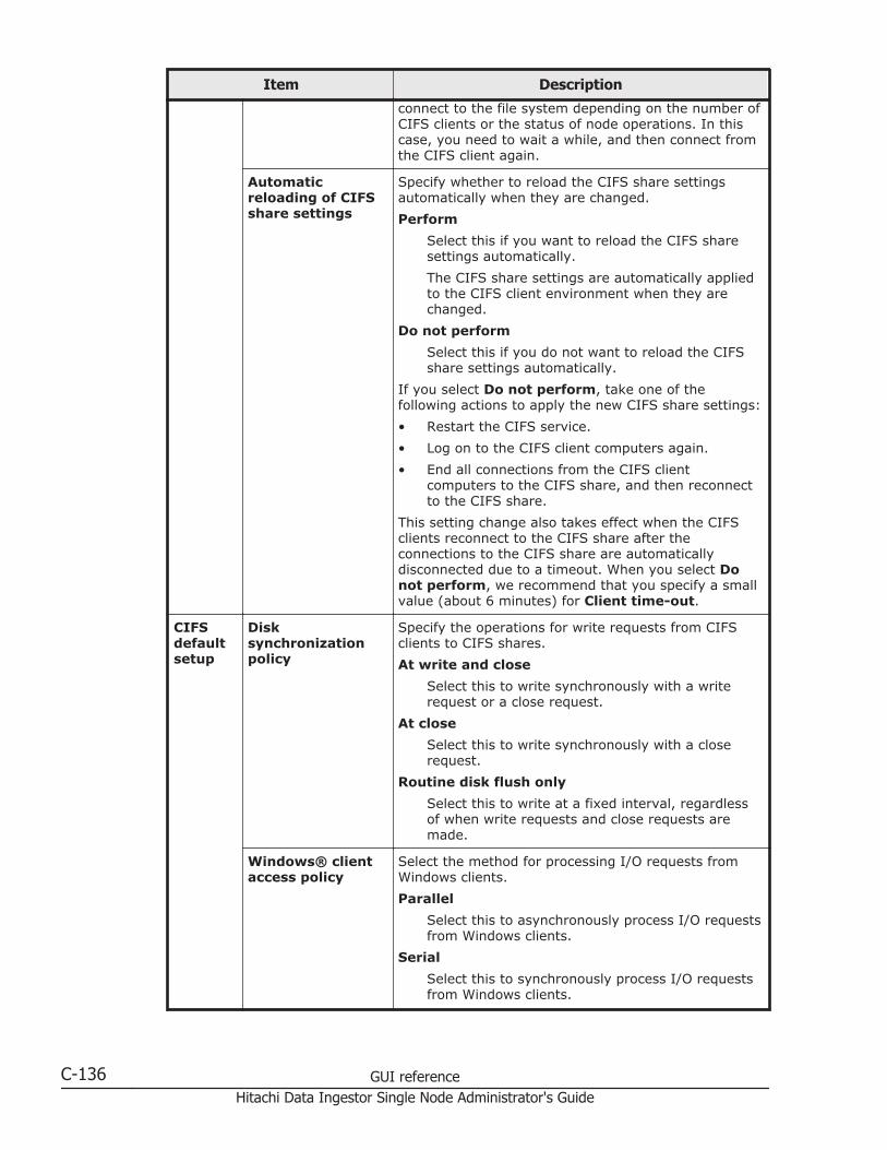
Item Description
connect to the file system depending on the number ofCIFS clients or the status of node operations. In thiscase, you need to wait a while, and then connect fromthe CIFS client again.
Automaticreloading of CIFSshare settings
Specify whether to reload the CIFS share settingsautomatically when they are changed.
Perform
Select this if you want to reload the CIFS sharesettings automatically.
The CIFS share settings are automatically appliedto the CIFS client environment when they arechanged.
Do not perform
Select this if you do not want to reload the CIFSshare settings automatically.
If you select Do not perform, take one of thefollowing actions to apply the new CIFS share settings:
• Restart the CIFS service.
• Log on to the CIFS client computers again.
• End all connections from the CIFS clientcomputers to the CIFS share, and then reconnectto the CIFS share.
This setting change also takes effect when the CIFSclients reconnect to the CIFS share after theconnections to the CIFS share are automaticallydisconnected due to a timeout. When you select Donot perform, we recommend that you specify a smallvalue (about 6 minutes) for Client time-out.
CIFSdefaultsetup
Disksynchronizationpolicy
Specify the operations for write requests from CIFSclients to CIFS shares.
At write and close
Select this to write synchronously with a writerequest or a close request.
At close
Select this to write synchronously with a closerequest.
Routine disk flush only
Select this to write at a fixed interval, regardlessof when write requests and close requests aremade.
Windows® clientaccess policy
Select the method for processing I/O requests fromWindows clients.
Parallel
Select this to asynchronously process I/O requestsfrom Windows clients.
Serial
Select this to synchronously process I/O requestsfrom Windows clients.
C-136 GUI referenceHitachi Data Ingestor Single Node Administrator's Guide
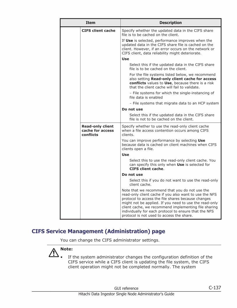
Item Description
CIFS client cache Specify whether the updated data in the CIFS sharefile is to be cached on the client.
If Use is selected, performance improves when theupdated data in the CIFS share file is cached on theclient. However, if an error occurs on the network orCIFS client, data reliability might deteriorate.
Use
Select this if the updated data in the CIFS sharefile is to be cached on the client.
For the file systems listed below, we recommendalso setting Read-only client cache for accessconflicts values to Use, because there is a riskthat the client cache will fail to validate.
- File systems for which the single-instancing offile data is enabled
- File systems that migrate data to an HCP system
Do not use
Select this if the updated data in the CIFS sharefile is not to be cached on the client.
Read-only clientcache for accessconflicts
Specify whether to use the read-only client cachewhen a file access contention occurs among CIFSclients.
You can improve performance by selecting Usebecause data is cached on client machines when CIFSclients open a file.
Use
Select this to use the read-only client cache. Youcan specify this only when Use is selected forCIFS client cache.
Do not use
Select this if you do not want to use the read-onlyclient cache.
Note that we recommend that you do not use theread-only client cache if you also want to use the NFSprotocol to access the file shares because changesmight not be applied. If you need to use the read-onlyclient cache, we recommend implementing file sharingindividually for each protocol to ensure that the NFSprotocol is not used to access the share.
CIFS Service Management (Administration) pageYou can change the CIFS administrator settings.
Note:
• If the system administrator changes the configuration definition of theCIFS service while a CIFS client is updating the file system, the CIFSclient operation might not be completed normally. The system
GUI reference C-137Hitachi Data Ingestor Single Node Administrator's Guide
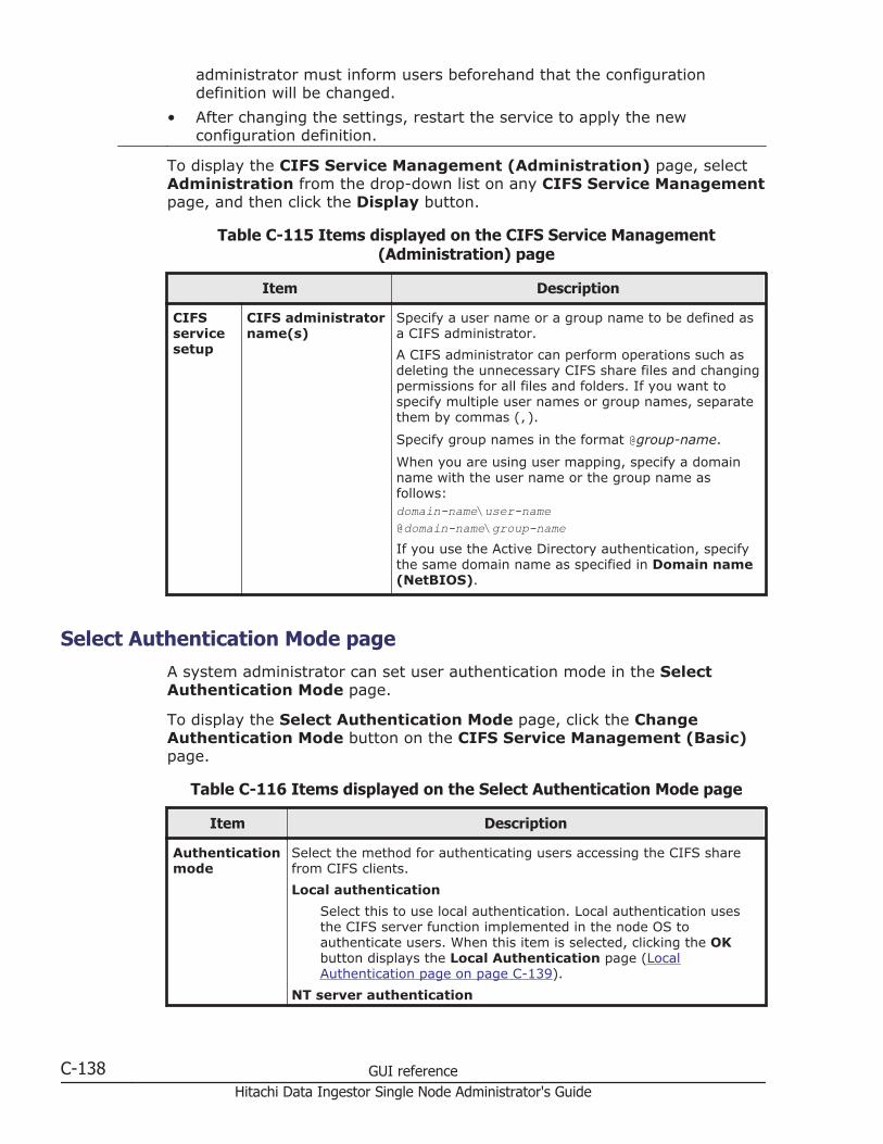
administrator must inform users beforehand that the configurationdefinition will be changed.
• After changing the settings, restart the service to apply the newconfiguration definition.
To display the CIFS Service Management (Administration) page, selectAdministration from the drop-down list on any CIFS Service Managementpage, and then click the Display button.
Table C-115 Items displayed on the CIFS Service Management(Administration) page
Item Description
CIFSservicesetup
CIFS administratorname(s)
Specify a user name or a group name to be defined asa CIFS administrator.
A CIFS administrator can perform operations such asdeleting the unnecessary CIFS share files and changingpermissions for all files and folders. If you want tospecify multiple user names or group names, separatethem by commas (,).
Specify group names in the format @group-name.
When you are using user mapping, specify a domainname with the user name or the group name asfollows:domain-name\user-name@domain-name\group-nameIf you use the Active Directory authentication, specifythe same domain name as specified in Domain name(NetBIOS).
Select Authentication Mode pageA system administrator can set user authentication mode in the SelectAuthentication Mode page.
To display the Select Authentication Mode page, click the ChangeAuthentication Mode button on the CIFS Service Management (Basic)page.
Table C-116 Items displayed on the Select Authentication Mode page
Item Description
Authenticationmode
Select the method for authenticating users accessing the CIFS sharefrom CIFS clients.
Local authentication
Select this to use local authentication. Local authentication usesthe CIFS server function implemented in the node OS toauthenticate users. When this item is selected, clicking the OKbutton displays the Local Authentication page (LocalAuthentication page on page C-139).
NT server authentication
C-138 GUI referenceHitachi Data Ingestor Single Node Administrator's Guide

Item Description
Select this to use NT server authentication when IPv4 is used. NTserver authentication authenticates users on a Windows NT serverthat is not used as the domain controller. Users who areauthenticated locally in an HDI system cannot access CIFS shares,because users are managed by the specified Windows NT server.
When this item is selected, clicking the OK button displays the NTServer Authentication page (NT Server Authentication page onpage C-140).
NT domain authentication
Select this to use NT domain authentication when IPv4 is used. NTdomain authentication authenticates users with the domaincontroller in the domain. Users who are authenticated locally in anHDI system cannot access CIFS shares, because users aremanaged by the corresponding domain controller.
If you set that user mapping is not to be used, the userinformation registered on the domain controller needs to beregistered in the HDI system, on the NIS server, or on the LDAPserver used for user authentication. For this reason, werecommend that you use user mapping when authenticating usersby NT domain authentication.
When this item is selected, clicking the OK button displays the NTDomain Authentication page (NT Domain Authentication pageon page C-140).
Active Directory authentication
Select this to use Active Directory authentication. Active Directoryauthentication uses the Active Directory domain controller toauthenticate users. Users who are authenticated locally in an HDIsystem cannot access CIFS shares, because users are managed bythe Active Directory domain controller.
If you set that user mapping is not to be used, the userinformation registered on the domain controller will need to beregistered in the HDI system, on the NIS server, or on the LDAPserver used for user authentication. For this reason, werecommend that you use user mapping when authenticating usersby Active Directory authentication.
When this item is selected, clicking the OK button displays theActive Directory Authentication page (Active DirectoryAuthentication page on page C-141).
Local Authentication pageA system administrator can set local authentication in the LocalAuthentication page.
To display the Local Authentication page, select Local authentication forAuthentication mode on the Select Authentication Mode page, and thenclick the OK button.
GUI reference C-139Hitachi Data Ingestor Single Node Administrator's Guide
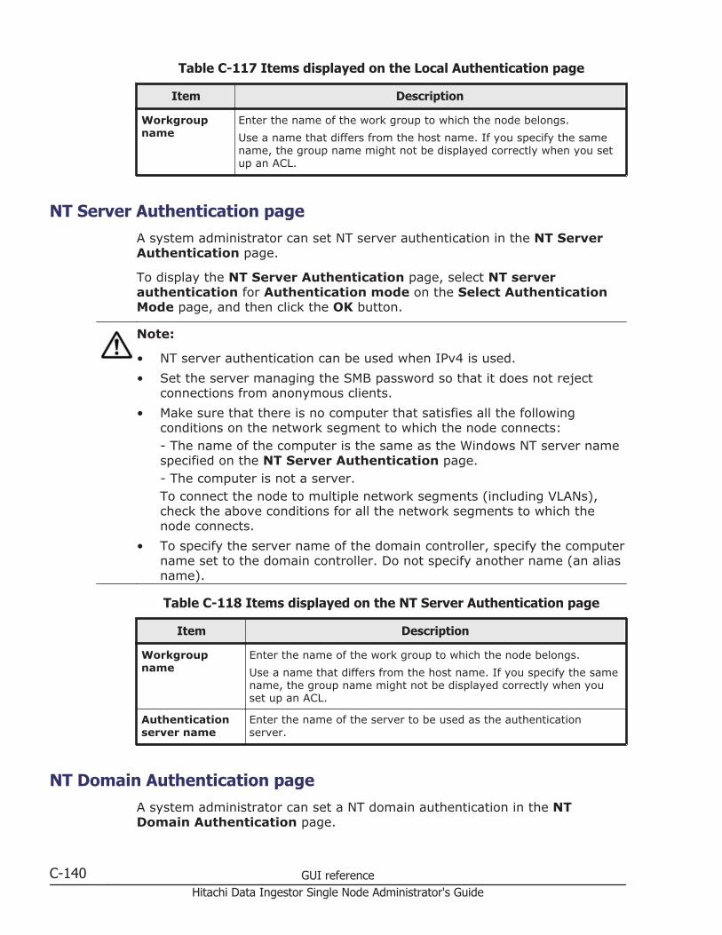
Table C-117 Items displayed on the Local Authentication page
Item Description
Workgroupname
Enter the name of the work group to which the node belongs.
Use a name that differs from the host name. If you specify the samename, the group name might not be displayed correctly when you setup an ACL.
NT Server Authentication pageA system administrator can set NT server authentication in the NT ServerAuthentication page.
To display the NT Server Authentication page, select NT serverauthentication for Authentication mode on the Select AuthenticationMode page, and then click the OK button.
Note:
• NT server authentication can be used when IPv4 is used.
• Set the server managing the SMB password so that it does not rejectconnections from anonymous clients.
• Make sure that there is no computer that satisfies all the followingconditions on the network segment to which the node connects:- The name of the computer is the same as the Windows NT server namespecified on the NT Server Authentication page.- The computer is not a server.To connect the node to multiple network segments (including VLANs),check the above conditions for all the network segments to which thenode connects.
• To specify the server name of the domain controller, specify the computername set to the domain controller. Do not specify another name (an aliasname).
Table C-118 Items displayed on the NT Server Authentication page
Item Description
Workgroupname
Enter the name of the work group to which the node belongs.
Use a name that differs from the host name. If you specify the samename, the group name might not be displayed correctly when youset up an ACL.
Authenticationserver name
Enter the name of the server to be used as the authenticationserver.
NT Domain Authentication pageA system administrator can set a NT domain authentication in the NTDomain Authentication page.
C-140 GUI referenceHitachi Data Ingestor Single Node Administrator's Guide
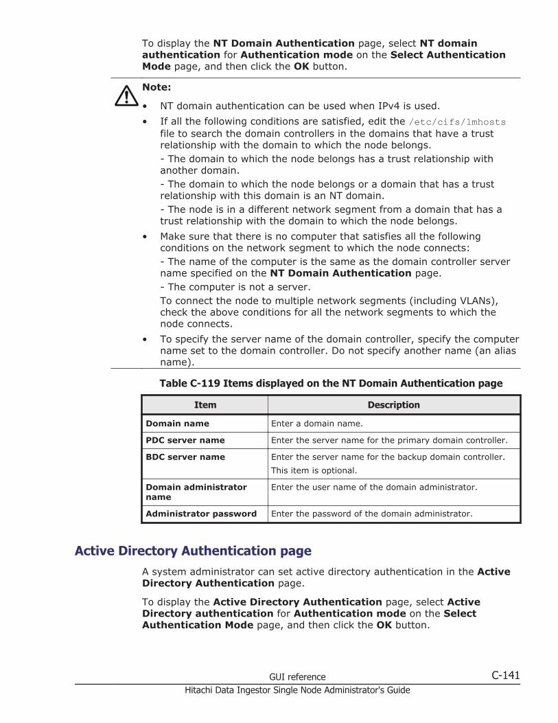
To display the NT Domain Authentication page, select NT domainauthentication for Authentication mode on the Select AuthenticationMode page, and then click the OK button.
Note:
• NT domain authentication can be used when IPv4 is used.
• If all the following conditions are satisfied, edit the /etc/cifs/lmhostsfile to search the domain controllers in the domains that have a trustrelationship with the domain to which the node belongs.- The domain to which the node belongs has a trust relationship withanother domain.- The domain to which the node belongs or a domain that has a trustrelationship with this domain is an NT domain.- The node is in a different network segment from a domain that has atrust relationship with the domain to which the node belongs.
• Make sure that there is no computer that satisfies all the followingconditions on the network segment to which the node connects:- The name of the computer is the same as the domain controller servername specified on the NT Domain Authentication page.- The computer is not a server.To connect the node to multiple network segments (including VLANs),check the above conditions for all the network segments to which thenode connects.
• To specify the server name of the domain controller, specify the computername set to the domain controller. Do not specify another name (an aliasname).
Table C-119 Items displayed on the NT Domain Authentication page
Item Description
Domain name Enter a domain name.
PDC server name Enter the server name for the primary domain controller.
BDC server name Enter the server name for the backup domain controller.
This item is optional.
Domain administratorname
Enter the user name of the domain administrator.
Administrator password Enter the password of the domain administrator.
Active Directory Authentication pageA system administrator can set active directory authentication in the ActiveDirectory Authentication page.
To display the Active Directory Authentication page, select ActiveDirectory authentication for Authentication mode on the SelectAuthentication Mode page, and then click the OK button.
GUI reference C-141Hitachi Data Ingestor Single Node Administrator's Guide
Note:
• Make sure that the DNS server you are using in the Active Directorydomain satisfies the following conditions:- The IP address of the node and the corresponding host name have beenregistered.- The SRV record that indicates the Active Directory service has beenregistered.- All the registered IP addresses corresponding to the host names of thedomain controllers can be used for communication from the node.- IP addresses corresponding to the host names of the domain controllersare not dynamically added.
• When you change the Active Directory domain to which the node belongs,beware of the following:- If you change the Active Directory domain and soon set the node tobelong to the old Active Directory domain, authentication of CIFS clientsmight result in an error even if the processing finishes normally. On theCIFS Service Maintenance page, click the Rejoin Active DirectoryDomain button to add the node to the Active Directory domain again.- If the node joins an Active Directory domain that is different from theold domain, but that has the same name as the old domain, unnecessarycomputer accounts might remain in the old Active Directory domain. Ifaccounts remain, use the domain controller in the old Active Directorydomain to delete the unnecessary computer accounts.
• If all the following conditions are satisfied, edit the /etc/cifs/lmhostsfile to search the domain controllers in the domains that have a trustrelationship with the domain to which the node belongs.- The domain to which the node belongs has a trust relationship withanother domain.- The domain to which the node belongs or a domain that has a trustrelationship with this domain is an NT domain.- The node is on a different network segment from a domain that has atrust relationship with the domain to which the node belongs.
• Try to maintain nearly the same time for the domain controller, the HDIsystem, and the CIFS clients. If the time differs by five minutes or more,authentication might fail when a CIFS client accesses the HDI system.
• If a user registered in the domain accesses the CIFS share provided bythe HDI system from a client computer that is not registered in thedomain, the user authentication might fail. If authentication fails, on theCIFS Service Maintenance page, check whether the NetBIOS name ofthe Active Directory domain has been set correctly.
• To specify the server name of the domain controller, specify the computername set to the domain controller. Do not specify another name (an aliasname).
C-142 GUI referenceHitachi Data Ingestor Single Node Administrator's Guide

Table C-120 Items displayed on the Active Directory Authentication page
Item Description
Domain name Enter the DNS name of the Active Directory domain.
Any lower-case letters that are entered are treated as upper-caseletters.
• If both the Active Directory domain controller and the KDCserver are used as one server:
The name specified here will also be used as the name of thedomain to which the KDC server belongs.
• If, in the configuration definition of the NFS service, the domainname is set to be applied to the NFSv4 domain:
The name specified here will also be used as the NFSv4 domainname.
• When an FTP or SFTP service setting is used to determinewhether users authenticated by Active Directory are permittedto log on:
The name specified here will also be used as the domain namefor the FTP or SFTP service.
Domainname(NetBIOS)
Enter the NetBIOS name of the Active Directory domain.
DC servername(s)
Specify the server name for the Active Directory domain controller towhich the nodes belong. You can also specify the IP address.
Up to five server names can be specified. When specifying multiplenames, separate each with a comma (,).
• If both the Active Directory domain controller and the KDCserver are used as one server:
The name specified here will also be used as the name of theKDC server.
• When an FTP or SFTP service setting is used to determinewhether users authenticated by Active Directory are permittedto log on:
The name specified here will also be used as the domain namefor the FTP or SFTP service.
Domain username
Specify the name of the Active Directory domain controller user.
When specifying the name of the Active Directory domain controlleruser, keep the following points in mind:
• If more than 10 servers are joined to the Active Directorydomain, the user must belong to the Account Operators group.
• If you want to change the domain user, before changing thesetting in the HDI system, delete the HDI account from theComputers container in the domain controller, or add a newdomain user to the HDI account and give the following accesspermissions to the user:
- Read- Validated write to DNS host name- Validated write to service principal name- Reset Password
GUI reference C-143Hitachi Data Ingestor Single Node Administrator's Guide

Item Description- Change Password- Write Account Restrictions
Domain userpassword
Enter the password of the user that is specified for Domain username.
Setting Events Logged to the CIFS Access Log pageThe Setting Events Logged to the CIFS Access Log page can be used tospecify an event that triggers collection of the CIFS access log.
Specified settings are applied to the whole CIFS service. However, if eventsthat trigger collection of the CIFS access log are specified for each CIFS shareby using the cifscreate command or the cifsedit command, the settingsfor each CIFS share are given priority over the settings for the whole CIFSservice. When the settings for the CIFS service are changed, check thesettings for each CIFS share as well as the settings for the whole CIFSservice.
To display the Setting Events Logged to the CIFS Access Log page, clickthe Set Up button on Events logged to the CIFS access log from theCIFS Service Management (Security) page in the Access ProtocolConfiguration dialog box.
Table C-121 Items displayed on the Setting Events Logged to the CIFSAccess Log page
Item Description
Events logged to the CIFSaccess log
Specify the events that trigger collection of the CIFSaccess log.
Successful
Select the check boxes for desired events (from theitems shown below) if you want a successful accesscorresponding to one of those events to trigger thecollection of the CIFS access log.
Failed
Select the check boxes for desired events (from theitems shown below) if you want a failed accesscorresponding to one of those events to trigger thecollection of the CIFS access log.
Each of the following items is used to specify an event (oraccess):
• List folder contents
• Read data
• Create files or write data
• Create folders
• Delete items
• Read permissions
C-144 GUI referenceHitachi Data Ingestor Single Node Administrator's Guide

Item Description
• Change permissions
• Change ownership
• Rename items
• Connect to or disconnect from shares
FTP Service Management pageYou can change the configuration definition of an FTP service.
Note:
• When the system administrator changes the configuration definitions ofthe FTP service, anonymous users are allowed to log on by using the FTPservice. If an anonymous user logs on to the FTP service, the name ftp isused for the user name and group name.
• The service does not automatically restart even when the configurationdefinitions of the FTP service have been changed. If the configurationdefinitions of the FTP service have been changed, restart the service byclicking Restart in the List of Services page.
• Even if the node is restarted after the configuration definitions of the FTPservice are modified, the modified configuration definitions are notapplied. Restart the service.
• If the system administrator changes the configuration definitions of theFTP service while a client is updating the file system, the client operationmight not finish normally. The system administrator must contact usersbefore changing the configuration definitions.
• When the chmod command is run on an FTP client for a file or directory forwhich an ACL is set, the ACL settings might become invalid. In this case,set the ACL again.
To display the FTP Service Management page, select FTP for Servicename on the List of Services page, and then click the ModifyConfiguration button.
Table C-122 Items displayed on the FTP Service Management page
Item Description
Specificationmethod for a logindirectory
Select the method of setting a directory to which the users can logon by using the FTP service.
All mounted file systems can be used.
Log on to the /mnt directory. This setting allows use of all filesystems mounted on each node.
Only the specified directory can be used.
Log on to a specified file system or directory. This settingallows users to use only the specified file systems ordirectories.
GUI reference C-145Hitachi Data Ingestor Single Node Administrator's Guide
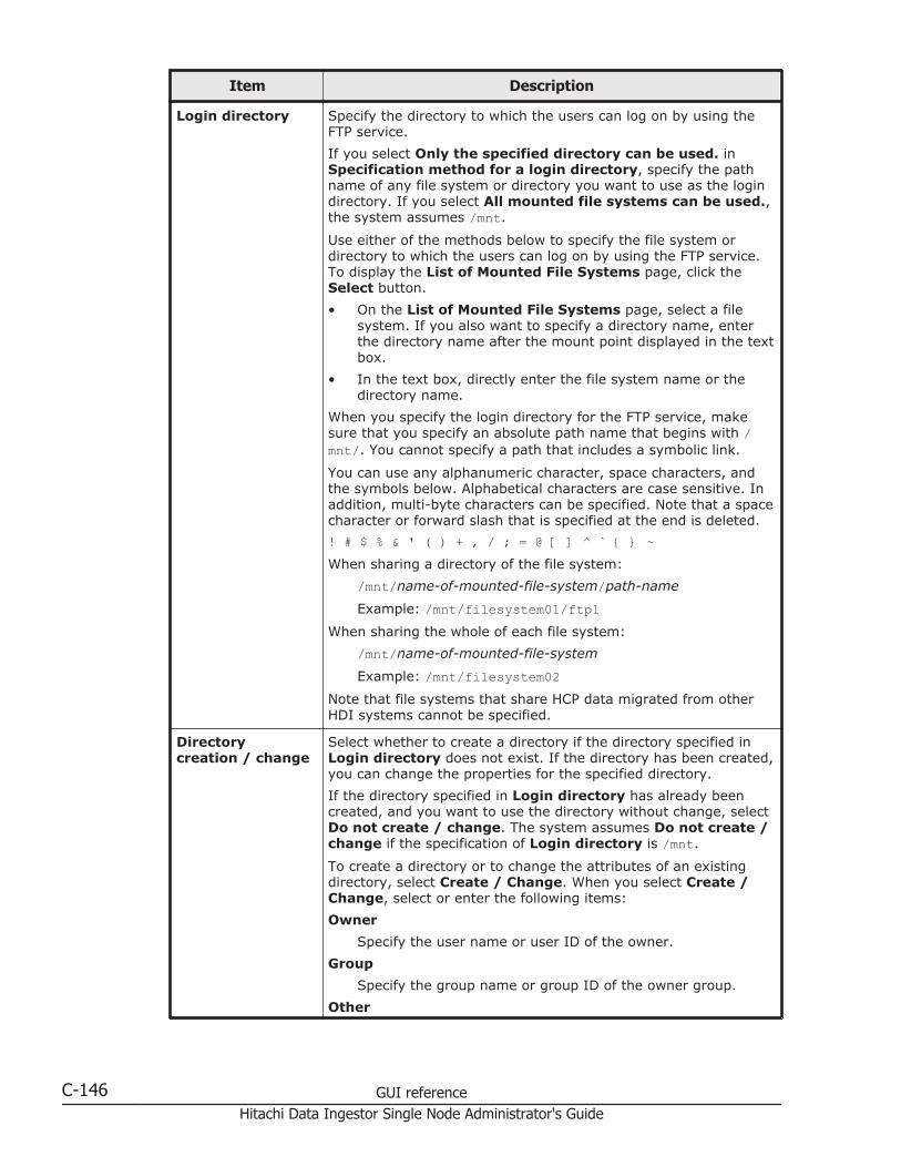
Item Description
Login directory Specify the directory to which the users can log on by using theFTP service.
If you select Only the specified directory can be used. inSpecification method for a login directory, specify the pathname of any file system or directory you want to use as the logindirectory. If you select All mounted file systems can be used.,the system assumes /mnt.
Use either of the methods below to specify the file system ordirectory to which the users can log on by using the FTP service.To display the List of Mounted File Systems page, click theSelect button.
• On the List of Mounted File Systems page, select a filesystem. If you also want to specify a directory name, enterthe directory name after the mount point displayed in the textbox.
• In the text box, directly enter the file system name or thedirectory name.
When you specify the login directory for the FTP service, makesure that you specify an absolute path name that begins with /mnt/. You cannot specify a path that includes a symbolic link.
You can use any alphanumeric character, space characters, andthe symbols below. Alphabetical characters are case sensitive. Inaddition, multi-byte characters can be specified. Note that a spacecharacter or forward slash that is specified at the end is deleted.
! # $ % & ' ( ) + , / ; = @ [ ] ^ ` { } ~When sharing a directory of the file system:
/mnt/name-of-mounted-file-system/path-name
Example: /mnt/filesystem01/ftp1When sharing the whole of each file system:
/mnt/name-of-mounted-file-system
Example: /mnt/filesystem02Note that file systems that share HCP data migrated from otherHDI systems cannot be specified.
Directorycreation / change
Select whether to create a directory if the directory specified inLogin directory does not exist. If the directory has been created,you can change the properties for the specified directory.
If the directory specified in Login directory has already beencreated, and you want to use the directory without change, selectDo not create / change. The system assumes Do not create /change if the specification of Login directory is /mnt.
To create a directory or to change the attributes of an existingdirectory, select Create / Change. When you select Create /Change, select or enter the following items:
Owner
Specify the user name or user ID of the owner.
Group
Specify the group name or group ID of the owner group.
Other
C-146 GUI referenceHitachi Data Ingestor Single Node Administrator's Guide

Item Description
Set the directory access permissions for others.
Permission mode#
Select the access permission for the directory owner, theowner's group, or other entity.
- Read / WriteSelect this mode to grant both read and write permissions.The directory execution permission is granted.
- Read onlySelect this mode to grant read permissions only. The directoryexecution permission is granted.
- NoneSelect this mode when neither the read and write permissionsnor the directory execution permission is granted. This modeis available for Group and Other.
Sticky bit
Select whether to set a sticky bit for the directory.
Setting a sticky bit allows only the owner of the directory todelete or rename the files or directories under that directory.
- On
Set a sticky bit.
- Off
Do not set a sticky bit.
When you are using user mapping, specify a domain name withthe user name or the group name as follows:domain-name\user-namedomain-name\group-nameIf you use the Active Directory authentication, specify the samedomain name as specified in Domain name (NetBIOS).
Allowed users Specify the users to be allowed to log on by using the FTP service.
All users
Allow all users to log on by using the FTP service. Note thatthe users registered by user mapping cannot log on by usingthe FTP service. To allow the users authenticated by ActiveDirectory to log on, select Including Active Directoryusers.
Selected users
Allow the specified users to log on by using the FTP service.On the Select FTP Users page, select the users to beallowed to log on by using the FTP service. To display theSelect FTP Users page, click the Set Up button. You canselect a maximum of 2,000 users.
The number of users currently allowed to log on is displayedto the right of this item name in the following format:
Selected users(number-of-users users)
Number ofsimultaneousconnections
Specify the number of uses who can concurrently log on by usingthe FTP service.
GUI reference C-147Hitachi Data Ingestor Single Node Administrator's Guide

Item Description
Specify a number in the range from 10 to 500.
Connectiontimeout wait time
Specify the timeout for an automatic logout in seconds. If nooperation is performed within the timeout period after an FTPclient has logged on to the directory, the FTP client is logged outautomatically.
Specify a number in the range from 30 to 43200.
Anonymous usersettings
Select whether to allow anonymous users to log on by using theFTP service.
Allow anonymous logins
Select this to grant anonymous users permission to log on byusing the FTP service. Anonymous users can use the FTPservice with the ftp user (UID=97) and ftp group (GID=97)permissions.
To grant anonymous users permission to upload, select Allowuploads.
Do not allow anonymous logins
Do not allow anonymous users to log on by using the FTPservice.
#: Access permissions are set on a per-directory basis. Therefore, when the samedirectory is specified in Login directory for both the FTP and SFTP services, changingthe access permission for either service will also change the access permission for theother service. In this case, you do not need to restart the other server to apply thechange.
Note the following for directories that must be logged on from the FTPservice:
• A directory that an NFS client created by using a character encoding suchas EUC or JIS cannot be specified as a directory that is logged on to fromthe FTP service.
• If a command is executed after logging on from the FTP service, thedirectory specified for Login directory becomes the root directory.
List of Mounted File Systems pageYou can select which file systems users of the FTP or SFTP service can log onto.
Note: To allow access to a directory under a file system, on the FTP ServiceManagement page, enter the directory following the mount point displayedfor Login directory.
To display the List of Mounted File Systems page, on the FTP ServiceManagement page, click the Select button for Login directory.
C-148 GUI referenceHitachi Data Ingestor Single Node Administrator's Guide

Table C-123 Items displayed on the List of Mounted File Systems page
Item Description
File system Displays the mounted file system.
Mount point Displays the mount point for the file system.
Select FTP Users pageYou can select the users that are permitted to log on to use the FTP service.
To display the Select FTP Users page, on the FTP Service Managementpage, click the Set Up button under Allowed users.
Table C-124 Items displayed on the Select FTP Users page
Item Description
List ofselectableusers
Select the users who will use the FTP service. To narrow down theusers that are displayed, select the conditions from Condition, andthen click the Display button.
all
Displays all user names.
a to z, A to Z, or 0 to 9Displays user names that begin with the selected alphanumericcharacter.
other
Displays user names that begin with a character other than analphanumeric.
The total number of filtered users is displayed to the right ofCondition. A maximum of 1,000 users can be displayed at the sametime in List of selectable users. If the number of users exceeds1,000, you can use the following methods to specify the users that willbe displayed:
Range
Displays the sequence number of the user who is displayed at thebeginning of List of selectable users.
- Display button
Specify a value equal to or less than the total number of filteredusers, and then click the Display button. This displays 1,000users, beginning with the user whose sequence number youspecified. If you then select a different filter from Condition andclick the Display button, the value specified in Range is ignoredand users are displayed beginning with the first user.
- Prev button
Clicking the Prev button displays in sequential order the userspreceding the user displayed at the beginning of List ofselectable users. If the user displayed at the beginning of Listof selectable users is the first user, or if the total number offiltered users is 0, an error message appears when you click thePrev button.
GUI reference C-149Hitachi Data Ingestor Single Node Administrator's Guide
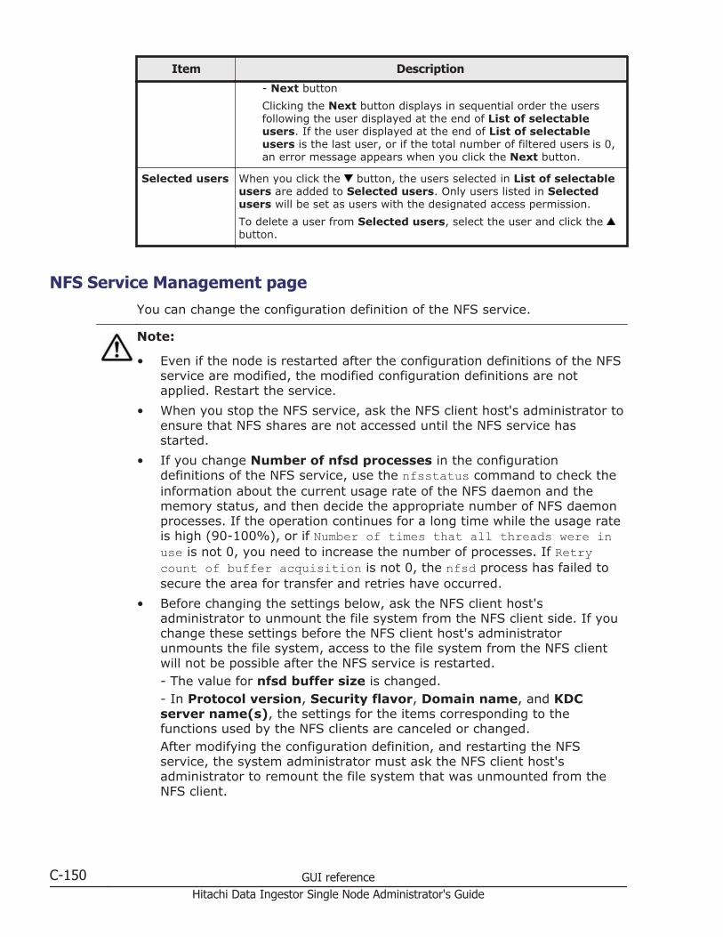
Item Description
- Next button
Clicking the Next button displays in sequential order the usersfollowing the user displayed at the end of List of selectableusers. If the user displayed at the end of List of selectableusers is the last user, or if the total number of filtered users is 0,an error message appears when you click the Next button.
Selected users When you click the button, the users selected in List of selectableusers are added to Selected users. Only users listed in Selectedusers will be set as users with the designated access permission.
To delete a user from Selected users, select the user and click the button.
NFS Service Management pageYou can change the configuration definition of the NFS service.
Note:
• Even if the node is restarted after the configuration definitions of the NFSservice are modified, the modified configuration definitions are notapplied. Restart the service.
• When you stop the NFS service, ask the NFS client host's administrator toensure that NFS shares are not accessed until the NFS service hasstarted.
• If you change Number of nfsd processes in the configurationdefinitions of the NFS service, use the nfsstatus command to check theinformation about the current usage rate of the NFS daemon and thememory status, and then decide the appropriate number of NFS daemonprocesses. If the operation continues for a long time while the usage rateis high (90-100%), or if Number of times that all threads were inuse is not 0, you need to increase the number of processes. If Retrycount of buffer acquisition is not 0, the nfsd process has failed tosecure the area for transfer and retries have occurred.
• Before changing the settings below, ask the NFS client host'sadministrator to unmount the file system from the NFS client side. If youchange these settings before the NFS client host's administratorunmounts the file system, access to the file system from the NFS clientwill not be possible after the NFS service is restarted.- The value for nfsd buffer size is changed.- In Protocol version, Security flavor, Domain name, and KDCserver name(s), the settings for the items corresponding to thefunctions used by the NFS clients are canceled or changed.After modifying the configuration definition, and restarting the NFSservice, the system administrator must ask the NFS client host'sadministrator to remount the file system that was unmounted from theNFS client.
C-150 GUI referenceHitachi Data Ingestor Single Node Administrator's Guide
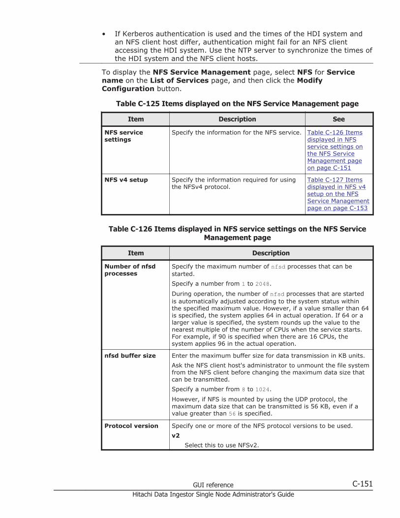
• If Kerberos authentication is used and the times of the HDI system andan NFS client host differ, authentication might fail for an NFS clientaccessing the HDI system. Use the NTP server to synchronize the times ofthe HDI system and the NFS client hosts.
To display the NFS Service Management page, select NFS for Servicename on the List of Services page, and then click the ModifyConfiguration button.
Table C-125 Items displayed on the NFS Service Management page
Item Description See
NFS servicesettings
Specify the information for the NFS service. Table C-126 Itemsdisplayed in NFSservice settings onthe NFS ServiceManagement pageon page C-151
NFS v4 setup Specify the information required for usingthe NFSv4 protocol.
Table C-127 Itemsdisplayed in NFS v4setup on the NFSService Managementpage on page C-153
Table C-126 Items displayed in NFS service settings on the NFS ServiceManagement page
Item Description
Number of nfsdprocesses
Specify the maximum number of nfsd processes that can bestarted.
Specify a number from 1 to 2048.
During operation, the number of nfsd processes that are startedis automatically adjusted according to the system status withinthe specified maximum value. However, if a value smaller than 64is specified, the system applies 64 in actual operation. If 64 or alarger value is specified, the system rounds up the value to thenearest multiple of the number of CPUs when the service starts.For example, if 90 is specified when there are 16 CPUs, thesystem applies 96 in the actual operation.
nfsd buffer size Enter the maximum buffer size for data transmission in KB units.
Ask the NFS client host's administrator to unmount the file systemfrom the NFS client before changing the maximum data size thatcan be transmitted.
Specify a number from 8 to 1024.
However, if NFS is mounted by using the UDP protocol, themaximum data size that can be transmitted is 56 KB, even if avalue greater than 56 is specified.
Protocol version Specify one or more of the NFS protocol versions to be used.
v2
Select this to use NFSv2.
GUI reference C-151Hitachi Data Ingestor Single Node Administrator's Guide
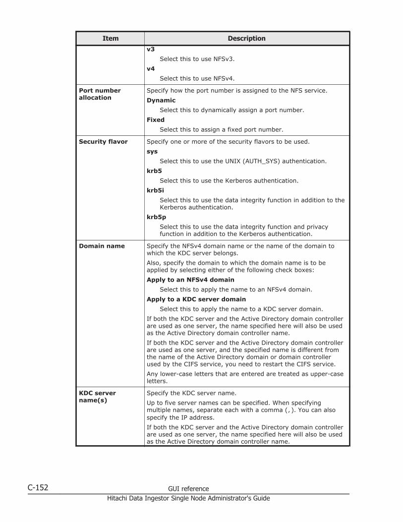
Item Description
v3
Select this to use NFSv3.
v4
Select this to use NFSv4.
Port numberallocation
Specify how the port number is assigned to the NFS service.
Dynamic
Select this to dynamically assign a port number.
Fixed
Select this to assign a fixed port number.
Security flavor Specify one or more of the security flavors to be used.
sys
Select this to use the UNIX (AUTH_SYS) authentication.
krb5
Select this to use the Kerberos authentication.
krb5i
Select this to use the data integrity function in addition to theKerberos authentication.
krb5p
Select this to use the data integrity function and privacyfunction in addition to the Kerberos authentication.
Domain name Specify the NFSv4 domain name or the name of the domain towhich the KDC server belongs.
Also, specify the domain to which the domain name is to beapplied by selecting either of the following check boxes:
Apply to an NFSv4 domain
Select this to apply the name to an NFSv4 domain.
Apply to a KDC server domain
Select this to apply the name to a KDC server domain.
If both the KDC server and the Active Directory domain controllerare used as one server, the name specified here will also be usedas the Active Directory domain controller name.
If both the KDC server and the Active Directory domain controllerare used as one server, and the specified name is different fromthe name of the Active Directory domain or domain controllerused by the CIFS service, you need to restart the CIFS service.
Any lower-case letters that are entered are treated as upper-caseletters.
KDC servername(s)
Specify the KDC server name.
Up to five server names can be specified. When specifyingmultiple names, separate each with a comma (,). You can alsospecify the IP address.
If both the KDC server and the Active Directory domain controllerare used as one server, the name specified here will also be usedas the Active Directory domain controller name.
C-152 GUI referenceHitachi Data Ingestor Single Node Administrator's Guide
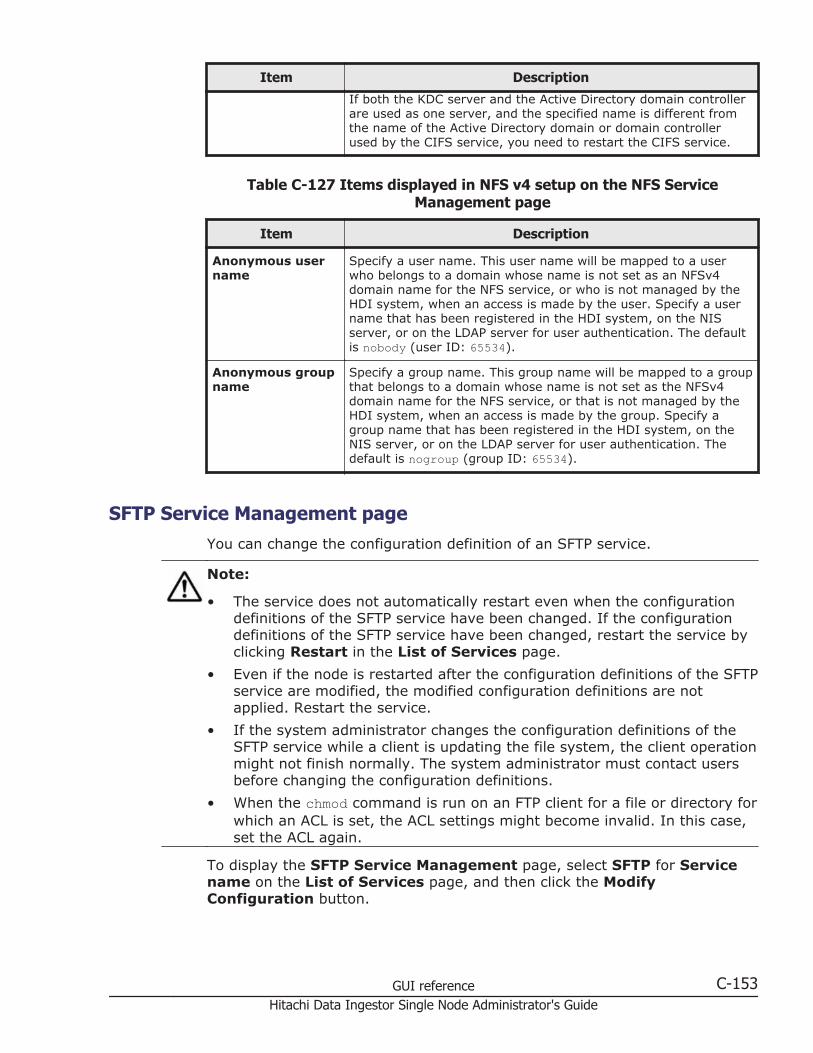
Item Description
If both the KDC server and the Active Directory domain controllerare used as one server, and the specified name is different fromthe name of the Active Directory domain or domain controllerused by the CIFS service, you need to restart the CIFS service.
Table C-127 Items displayed in NFS v4 setup on the NFS ServiceManagement page
Item Description
Anonymous username
Specify a user name. This user name will be mapped to a userwho belongs to a domain whose name is not set as an NFSv4domain name for the NFS service, or who is not managed by theHDI system, when an access is made by the user. Specify a username that has been registered in the HDI system, on the NISserver, or on the LDAP server for user authentication. The defaultis nobody (user ID: 65534).
Anonymous groupname
Specify a group name. This group name will be mapped to a groupthat belongs to a domain whose name is not set as the NFSv4domain name for the NFS service, or that is not managed by theHDI system, when an access is made by the group. Specify agroup name that has been registered in the HDI system, on theNIS server, or on the LDAP server for user authentication. Thedefault is nogroup (group ID: 65534).
SFTP Service Management pageYou can change the configuration definition of an SFTP service.
Note:
• The service does not automatically restart even when the configurationdefinitions of the SFTP service have been changed. If the configurationdefinitions of the SFTP service have been changed, restart the service byclicking Restart in the List of Services page.
• Even if the node is restarted after the configuration definitions of the SFTPservice are modified, the modified configuration definitions are notapplied. Restart the service.
• If the system administrator changes the configuration definitions of theSFTP service while a client is updating the file system, the client operationmight not finish normally. The system administrator must contact usersbefore changing the configuration definitions.
• When the chmod command is run on an FTP client for a file or directory forwhich an ACL is set, the ACL settings might become invalid. In this case,set the ACL again.
To display the SFTP Service Management page, select SFTP for Servicename on the List of Services page, and then click the ModifyConfiguration button.
GUI reference C-153Hitachi Data Ingestor Single Node Administrator's Guide
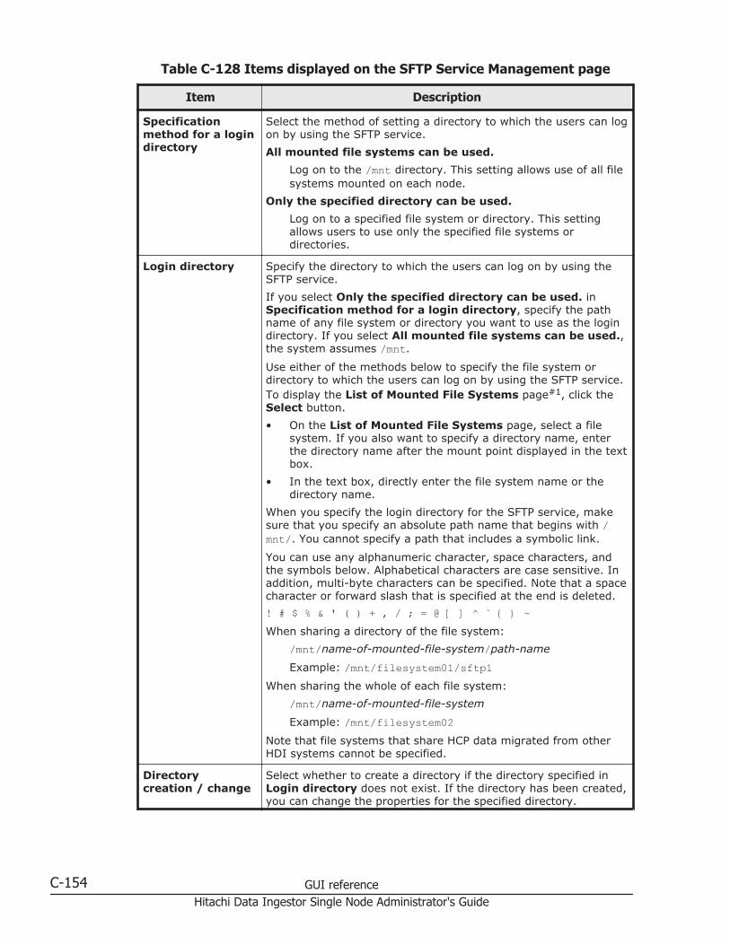
Table C-128 Items displayed on the SFTP Service Management page
Item Description
Specificationmethod for a logindirectory
Select the method of setting a directory to which the users can logon by using the SFTP service.
All mounted file systems can be used.
Log on to the /mnt directory. This setting allows use of all filesystems mounted on each node.
Only the specified directory can be used.
Log on to a specified file system or directory. This settingallows users to use only the specified file systems ordirectories.
Login directory Specify the directory to which the users can log on by using theSFTP service.
If you select Only the specified directory can be used. inSpecification method for a login directory, specify the pathname of any file system or directory you want to use as the logindirectory. If you select All mounted file systems can be used.,the system assumes /mnt.
Use either of the methods below to specify the file system ordirectory to which the users can log on by using the SFTP service.To display the List of Mounted File Systems page#1, click theSelect button.
• On the List of Mounted File Systems page, select a filesystem. If you also want to specify a directory name, enterthe directory name after the mount point displayed in the textbox.
• In the text box, directly enter the file system name or thedirectory name.
When you specify the login directory for the SFTP service, makesure that you specify an absolute path name that begins with /mnt/. You cannot specify a path that includes a symbolic link.
You can use any alphanumeric character, space characters, andthe symbols below. Alphabetical characters are case sensitive. Inaddition, multi-byte characters can be specified. Note that a spacecharacter or forward slash that is specified at the end is deleted.
! # $ % & ' ( ) + , / ; = @ [ ] ^ ` { } ~When sharing a directory of the file system:
/mnt/name-of-mounted-file-system/path-name
Example: /mnt/filesystem01/sftp1When sharing the whole of each file system:
/mnt/name-of-mounted-file-system
Example: /mnt/filesystem02Note that file systems that share HCP data migrated from otherHDI systems cannot be specified.
Directorycreation / change
Select whether to create a directory if the directory specified inLogin directory does not exist. If the directory has been created,you can change the properties for the specified directory.
C-154 GUI referenceHitachi Data Ingestor Single Node Administrator's Guide
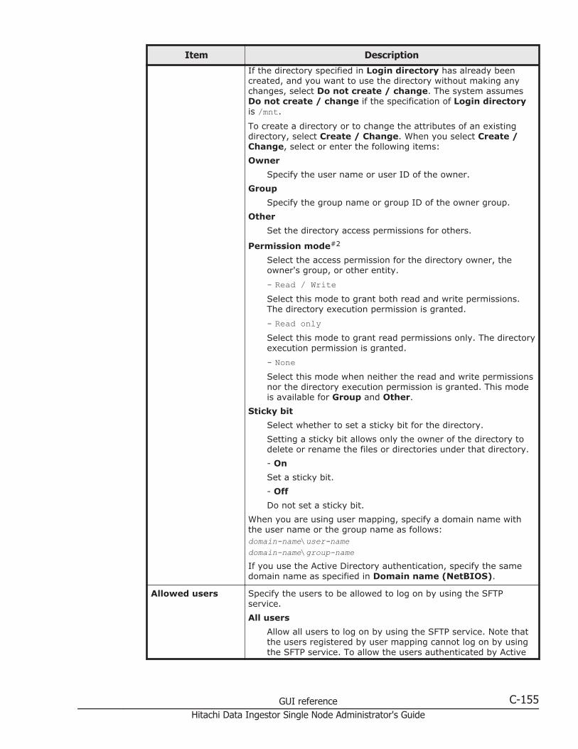
Item Description
If the directory specified in Login directory has already beencreated, and you want to use the directory without making anychanges, select Do not create / change. The system assumesDo not create / change if the specification of Login directoryis /mnt.
To create a directory or to change the attributes of an existingdirectory, select Create / Change. When you select Create /Change, select or enter the following items:
Owner
Specify the user name or user ID of the owner.
Group
Specify the group name or group ID of the owner group.
Other
Set the directory access permissions for others.
Permission mode#2
Select the access permission for the directory owner, theowner's group, or other entity.
- Read / WriteSelect this mode to grant both read and write permissions.The directory execution permission is granted.
- Read onlySelect this mode to grant read permissions only. The directoryexecution permission is granted.
- NoneSelect this mode when neither the read and write permissionsnor the directory execution permission is granted. This modeis available for Group and Other.
Sticky bit
Select whether to set a sticky bit for the directory.
Setting a sticky bit allows only the owner of the directory todelete or rename the files or directories under that directory.
- On
Set a sticky bit.
- Off
Do not set a sticky bit.
When you are using user mapping, specify a domain name withthe user name or the group name as follows:domain-name\user-namedomain-name\group-nameIf you use the Active Directory authentication, specify the samedomain name as specified in Domain name (NetBIOS).
Allowed users Specify the users to be allowed to log on by using the SFTPservice.
All users
Allow all users to log on by using the SFTP service. Note thatthe users registered by user mapping cannot log on by usingthe SFTP service. To allow the users authenticated by Active
GUI reference C-155Hitachi Data Ingestor Single Node Administrator's Guide
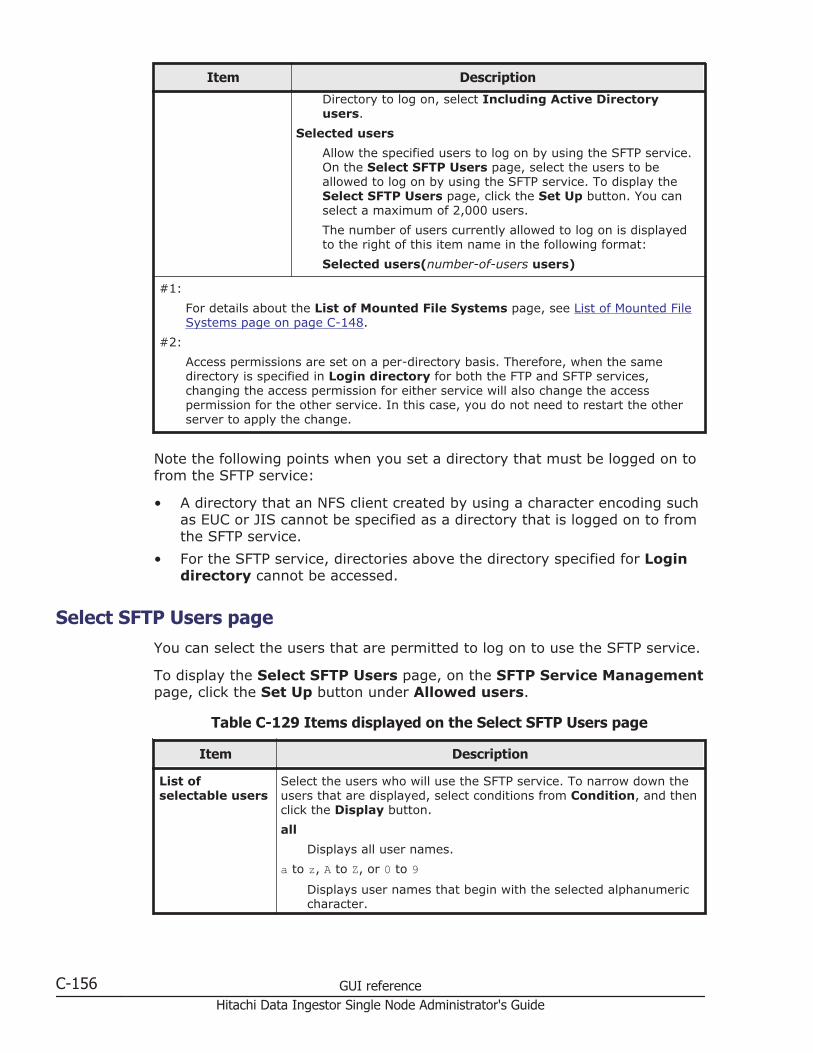
Item Description
Directory to log on, select Including Active Directoryusers.
Selected users
Allow the specified users to log on by using the SFTP service.On the Select SFTP Users page, select the users to beallowed to log on by using the SFTP service. To display theSelect SFTP Users page, click the Set Up button. You canselect a maximum of 2,000 users.
The number of users currently allowed to log on is displayedto the right of this item name in the following format:
Selected users(number-of-users users)
#1:
For details about the List of Mounted File Systems page, see List of Mounted FileSystems page on page C-148.
#2:
Access permissions are set on a per-directory basis. Therefore, when the samedirectory is specified in Login directory for both the FTP and SFTP services,changing the access permission for either service will also change the accesspermission for the other service. In this case, you do not need to restart the otherserver to apply the change.
Note the following points when you set a directory that must be logged on tofrom the SFTP service:
• A directory that an NFS client created by using a character encoding suchas EUC or JIS cannot be specified as a directory that is logged on to fromthe SFTP service.
• For the SFTP service, directories above the directory specified for Logindirectory cannot be accessed.
Select SFTP Users pageYou can select the users that are permitted to log on to use the SFTP service.
To display the Select SFTP Users page, on the SFTP Service Managementpage, click the Set Up button under Allowed users.
Table C-129 Items displayed on the Select SFTP Users page
Item Description
List ofselectable users
Select the users who will use the SFTP service. To narrow down theusers that are displayed, select conditions from Condition, and thenclick the Display button.
all
Displays all user names.
a to z, A to Z, or 0 to 9Displays user names that begin with the selected alphanumericcharacter.
C-156 GUI referenceHitachi Data Ingestor Single Node Administrator's Guide

Item Description
other
Displays user names that begin with a character other than analphanumeric.
The total number of filtered users is displayed to the right ofCondition. A maximum of 1,000 users can be displayed at the sametime in List of selectable users. If the number of users exceeds1,000, you can use the following methods to specify the users thatwill be displayed:
Range
Displays the sequence number of the user who is displayed atthe beginning of List of selectable users.
- Display button
Specify a value equal to or less than the total number of filteredusers, and then click the Display button. This displays 1,000users, beginning with the user whose sequence number youspecified. If you then select a different filter from Condition andclick the Display button, the value specified in Range isignored and users are displayed beginning with the first user.
- Prev button
Clicking the Prev button displays in sequential order the userspreceding the user displayed at the beginning of List ofselectable users. If the user displayed at the beginning of Listof selectable users is the first user, or if the total number offiltered users is 0, an error message appears when you click thePrev button.
- Next button
Clicking the Next button displays in sequential order the usersfollowing the user displayed at the end of List of selectableusers. If the user displayed at the end of List of selectableusers is the last user, or if the total number of filtered users is0, an error message appears when you click the Next button.
Selected users When you click the button, the users selected in List ofselectable users are added to Selected users. Only users listed inSelected users will be set as users with the designated accesspermission.
To delete a user from Selected users, select the user and click the button.
Public Key List pageYou can register and delete public keys.
To display the Public Key List page, select SSH for Service name on theList of Services page, and then click the Modify Configuration button.
GUI reference C-157Hitachi Data Ingestor Single Node Administrator's Guide
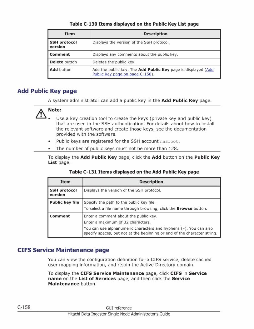
Table C-130 Items displayed on the Public Key List page
Item Description
SSH protocolversion
Displays the version of the SSH protocol.
Comment Displays any comments about the public key.
Delete button Deletes the public key.
Add button Add the public key. The Add Public Key page is displayed (AddPublic Key page on page C-158).
Add Public Key pageA system administrator can add a public key in the Add Public Key page.
Note:
• Use a key creation tool to create the keys (private key and public key)that are used in the SSH authentication. For details about how to installthe relevant software and create those keys, see the documentationprovided with the software.
• Public keys are registered for the SSH account nasroot.
• The number of public keys must not be more than 128.
To display the Add Public Key page, click the Add button on the Public KeyList page.
Table C-131 Items displayed on the Add Public Key page
Item Description
SSH protocolversion
Displays the version of the SSH protocol.
Public key file Specify the path to the public key file.
To select a file name through browsing, click the Browse button.
Comment Enter a comment about the public key.
Enter a maximum of 32 characters.
You can use alphanumeric characters and hyphens (-). You can alsospecify spaces, but not at the beginning or end of the character string.
CIFS Service Maintenance pageYou can view the configuration definition for a CIFS service, delete cacheduser mapping information, and rejoin the Active Directory domain.
To display the CIFS Service Maintenance page, click CIFS in Servicename on the List of Services page, and then click the ServiceMaintenance button.
C-158 GUI referenceHitachi Data Ingestor Single Node Administrator's Guide

Table C-132 Items displayed on the CIFS Service Maintenance page
Item Description
CIFS service informationarea
Displays information about the operating status of theCIFS service. For details about the items displayed, seeTable C-133 Items displayed on the CIFS serviceinformation area of the CIFS Service Maintenance page onpage C-159.
CIFS default informationarea
Displays information about accesses from the clients. Fordetails about the items displayed, see Table C-134 Itemsdisplayed on the CIFS default information area of the CIFSService Maintenance page on page C-163.
User mappinginformation area
Displays information about user mapping. The displayedinformation differs depending on which user mappingmethod is used. For details about the items displayed, seeTable C-135 Items displayed in the User mappinginformation area of the CIFS Service Maintenance page(when user mapping uses RIDs) on page C-165, TableC-136 Items displayed in the User mapping informationarea of the CIFS Service Maintenance page (when usermapping uses LDAP) on page C-165, or Table C-137 Itemsdisplayed in the User mapping information area of theCIFS Service Maintenance page (when user mapping usesthe Active Directory schema) on page C-167.
If user mapping is not used, Not used is displayed forUser mapping usage type.
Clear User Map Cache Filebutton
Deletes cached user mapping information.
Rejoin Active DirectoryDomain button
Rejoins the Active Directory domain.
Redefine Active DirectoryDomain button
Redefine the domain with which a trust relationship is tobe established.
Table C-133 Items displayed on the CIFS service information area of theCIFS Service Maintenance page
Item Description
Service status Displays the status of the CIFS service.
RunningDisplayed when the CIFS service is running normally.
DownDisplayed when the service is running in an incompletestate.
OfflineDisplayed when the resource group is stopped.
StoppedDisplayed when the CIFS service is stopped.
GUI reference C-159Hitachi Data Ingestor Single Node Administrator's Guide
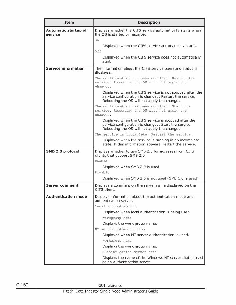
Item Description
Automatic startup ofservice
Displays whether the CIFS service automatically starts whenthe OS is started or restarted.
OnDisplayed when the CIFS service automatically starts.
OffDisplayed when the CIFS service does not automaticallystart.
Service information The information about the CIFS service operating status isdisplayed.
The configuration has been modified. Restart theservice. Rebooting the OS will not apply thechanges.
Displayed when the CIFS service is not stopped after theservice configuration is changed. Restart the service.Rebooting the OS will not apply the changes.
The configuration has been modified. Start theservice. Rebooting the OS will not apply thechanges.
Displayed when the CIFS service is stopped after theservice configuration is changed. Start the service.Rebooting the OS will not apply the changes.
The service is incomplete. Restart the service.Displayed when the service is running in an incompletestate. If this information appears, restart the service.
SMB 2.0 protocol Displays whether to use SMB 2.0 for accesses from CIFSclients that support SMB 2.0.
EnableDisplayed when SMB 2.0 is used.
DisableDisplayed when SMB 2.0 is not used (SMB 1.0 is used).
Server comment Displays a comment on the server name displayed on theCIFS client.
Authentication mode Displays information about the authentication mode andauthentication server.
Local authenticationDisplayed when local authentication is being used.
Workgroup nameDisplays the work group name.
NT server authenticationDisplayed when NT server authentication is used.
Workgroup nameDisplays the work group name.
Authentication server nameDisplays the name of the Windows NT server that is usedas an authentication server.
C-160 GUI referenceHitachi Data Ingestor Single Node Administrator's Guide
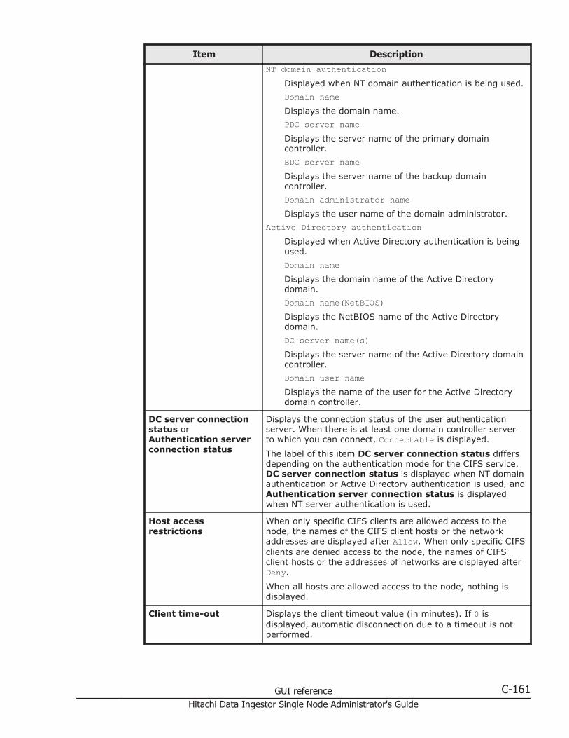
Item DescriptionNT domain authentication
Displayed when NT domain authentication is being used.
Domain nameDisplays the domain name.
PDC server nameDisplays the server name of the primary domaincontroller.
BDC server nameDisplays the server name of the backup domaincontroller.
Domain administrator nameDisplays the user name of the domain administrator.
Active Directory authenticationDisplayed when Active Directory authentication is beingused.
Domain nameDisplays the domain name of the Active Directorydomain.
Domain name(NetBIOS)Displays the NetBIOS name of the Active Directorydomain.
DC server name(s)Displays the server name of the Active Directory domaincontroller.
Domain user nameDisplays the name of the user for the Active Directorydomain controller.
DC server connectionstatus orAuthentication serverconnection status
Displays the connection status of the user authenticationserver. When there is at least one domain controller serverto which you can connect, Connectable is displayed.
The label of this item DC server connection status differsdepending on the authentication mode for the CIFS service.DC server connection status is displayed when NT domainauthentication or Active Directory authentication is used, andAuthentication server connection status is displayedwhen NT server authentication is used.
Host accessrestrictions
When only specific CIFS clients are allowed access to thenode, the names of the CIFS client hosts or the networkaddresses are displayed after Allow. When only specific CIFSclients are denied access to the node, the names of CIFSclient hosts or the addresses of networks are displayed afterDeny.
When all hosts are allowed access to the node, nothing isdisplayed.
Client time-out Displays the client timeout value (in minutes). If 0 isdisplayed, automatic disconnection due to a timeout is notperformed.
GUI reference C-161Hitachi Data Ingestor Single Node Administrator's Guide

Item Description
Mapping to guestaccount
Displays what kind of users will be treated as guests.
Unregistered usersDisplayed when users who have not been registered inthe system will be treated as guests.#
Unregistered users or invalid passwordsDisplayed when users who have not been registered inthe system or who have been registered in the systembut have an invalid password will be treated as guests.#
NeverDisplayed when guest access to the CIFS shares is notpermitted.
NetBIOS over TCP/IP Displays whether to accept access, from CIFS clients, thatuses NetBIOS over TCP/IP.
UseDisplayed when the CIFS service accepts access, fromCIFS clients, that uses NetBIOS over TCP/IP.
Do not useDisplayed when the CIFS service does not accept access,from CIFS clients, that uses NetBIOS over TCP/IP.
CIFS access log Displays whether the CIFS access log is collected.
UseDisplayed when the CIFS access log is collected.
Use (If the CIFS access log file exceeds the maxsize, do not collect log data.)
Displayed if the log file cannot be moved (when themove destination is not specified, or when the capacityof the file system to which the log file is to be moved hasreached the maximum limit), and if you want to stopcollecting the CIFS access log at the time when thecapacity of the log file reaches the maximum limit.
Do not useDisplayed when the CIFS access log is not collected.
Automatic reloading ofCIFS share settings
Displays whether the CIFS share settings are automaticallyreloaded when they are changed.
PerformDisplayed when the CIFS share settings areautomatically reloaded.
Do not performDisplayed when the CIFS share settings are notautomatically reloaded.
Max. number of CIFSclients accessiblesimultaneously
Displays the maximum value of CIFS clients that can accessa node.
CIFS administratorname(s)
When one or more users or groups have been set as CIFSadministrators, this item displays their user names or groupnames.
C-162 GUI referenceHitachi Data Ingestor Single Node Administrator's Guide

Item Description
Current number ofCIFS login clients
Displays the number of CIFS clients that are currently loggedon.
#: The users to be treated as guests differ depending on the authentication mode that iscurrently used (the mode displayed in Authentication mode):
• When Local authentication is being used
Users who are not registered by using local authentication are treated as guests.
• When NT server authentication is being used
Users who are not registered on the Windows NT server are treated as guests.
• When NT domain authentication is being used
Users who are not registered in the domain controller in the domain are treated asguests.
• When Active Directory authentication is being used
Users who are not registered in the Active Directory domain controller are treated asguests.
Table C-134 Items displayed on the CIFS default information area of theCIFS Service Maintenance page
Item Description
Guest account access Displays whether guest account users access is allowed forthe CIFS shares.
AllowDisplayed when guest account users access is allowed.
DisallowDisplayed when guest account users access isdisallowed.
Disk synchronizationpolicy
Displays operational settings for write requests from CIFSclients to CIFS shares.
At write and closeDisplayed when writing is performed synchronously witha write request or a close request.
At closeDisplayed when writing is performed synchronously witha close request.
Routine disk flush onlyDisplayed when writing is performed at a fixed interval,regardless of when write requests and close requests aremade.
Windows® clientaccess policy
Displays the method for processing accesses from Windowsclients.
ParallelDisplayed when accesses are processed in parallel.
SerialDisplayed when accesses are processed serially.
GUI reference C-163Hitachi Data Ingestor Single Node Administrator's Guide

Item Description
CIFS client cache Displays whether the updated data in the CIFS share file is tobe cached on the client.
UseDisplayed when the updated data in the CIFS share fileis to be cached on the client.
Do not useDisplayed when the updated data in the CIFS share fileis not to be cached on the client.
Read-only client cachefor access conflicts
Displays whether to use a read-only client cache whenmultiple CIFS clients simultaneously attempt to access a file.
UseDisplayed when a read-only client cache is used.
Do not useDisplayed when a read-only client cache is not used.
Volume Shadow CopyService
This item is not supported.
Access BasedEnumeration
Displays whether to use access-based enumeration.
UseDisplayed when access-based enumeration is used.
Do not useDisplayed when access-based enumeration is not used.
File timestampchangeable users
Displays the users for whom you allow updating of CIFSshare file timestamps.
Write permitted usersDisplayed when you permit updating of the CIFS sharefile timestamp for all users who are permitted to write tothis file.
Owner onlyDisplayed when you restrict timestamp updating to thefile owner.
Note that this setting is invalid in an advanced ACL filesystem. Only a user who has write permission can updatetimestamps.
Events logged to theCIFS access log
Displays the events that trigger the collection of the CIFSaccess log.
SuccessfulSelected the check boxes for desired events (from theitems shown below) when a successful accesscorresponding to one of these items triggers thecollection of the CIFS access log.
FailedSelected the check boxes for desired events (from theitems shown below) when a failed access correspondingto one of these items triggers the collection of the CIFSaccess log.
C-164 GUI referenceHitachi Data Ingestor Single Node Administrator's Guide

Item Description
Each of the following items is used to specify an event (oraccess):
• List folder contents
• Read data
• Create files or write data
• Create folders
• Delete items
• Read permissions
• Change permissions
• Change ownership
• Rename items
• Connect to or disconnect from shares
Table C-135 Items displayed in the User mapping information area of theCIFS Service Maintenance page (when user mapping uses RIDs)
Item Description
User mapping usage type Displays the type of user mapping being used. Ifuser mapping uses RIDs, RID is displayed.
Range of UIDs and GIDs Displays the range of user IDs and group IDsmapped by using RIDs.
Settings for each domain Displays the range of user IDs and group IDs set foreach domain.
When two or more ranges have been set, they aredisplayed in ascending order of the minimum valuefor the range of user IDs and group IDs.
Table C-136 Items displayed in the User mapping information area of theCIFS Service Maintenance page (when user mapping uses LDAP)
Item Description
User mapping usage type Displays the type of user mapping being used. Ifuser mapping uses LDAP, LDAP is displayed.
LDAP server name Displays the host name or IP address of the LDAPserver.
LDAP server port number Displays the port number of the LDAP server.
LDAP server root DN Displays the identification name of the LDAP serverroot in DN format.
LDAP user map DN Displays the identification name for which you addedthe user mapping account of the LDAP server in DNformat.
LDAP administrator DN Displays the identification name of the LDAP serveradministrator in DN format.
GUI reference C-165Hitachi Data Ingestor Single Node Administrator's Guide

Item Description
Allocation method Displays the method for allocating user IDs andgroup IDs.
AutomaticDisplayed when IDs are allocated automatically.
ManualDisplayed when IDs are allocated manually.
Range of UIDs Displays the range of user IDs mapped by usingLDAP.
This information is displayed only when the settingfor automatically assigning user IDs and group IDs isspecified.
Largest currently used UID Displays the largest user ID within the range of userIDs that have already been assigned in the HDIsystem.
This information is displayed only when the settingfor automatically assigning user IDs and group IDs isspecified.
Depending on the status of user mapping usage, thefollowing information might be displayed:
Not used, or less than the minimum UID used.Displayed when no user IDs have been assigned,or the smallest assigned user ID is smaller thanthe minimum value set in Range of UIDs.
Cannot be got from LDAP server. Check theLDAP server settings and CIFS serviceconfiguration in service.
Displayed when the largest ID could not beacquired from the LDAP server for user mapping.Check the user mapping settings and theoperating status of the LDAP server.
Range of GIDs Displays the range of group IDs mapped by usingLDAP.
This information is displayed only when the settingfor automatically assigning user IDs and group IDs isspecified.
Largest currently used GID Displays the largest group ID within the range ofgroup IDs that have already been assigned in theHDI system.
This item is displayed only when the setting forautomatically assigning user IDs and group IDs isspecified.
Depending on the status of user mapping usage, thefollowing information might be displayed:
Not used, or less than the minimum GID used.Displayed when no group IDs have beenassigned, or the smallest assigned group ID issmaller than the minimum value set in Range ofGIDs.
C-166 GUI referenceHitachi Data Ingestor Single Node Administrator's Guide
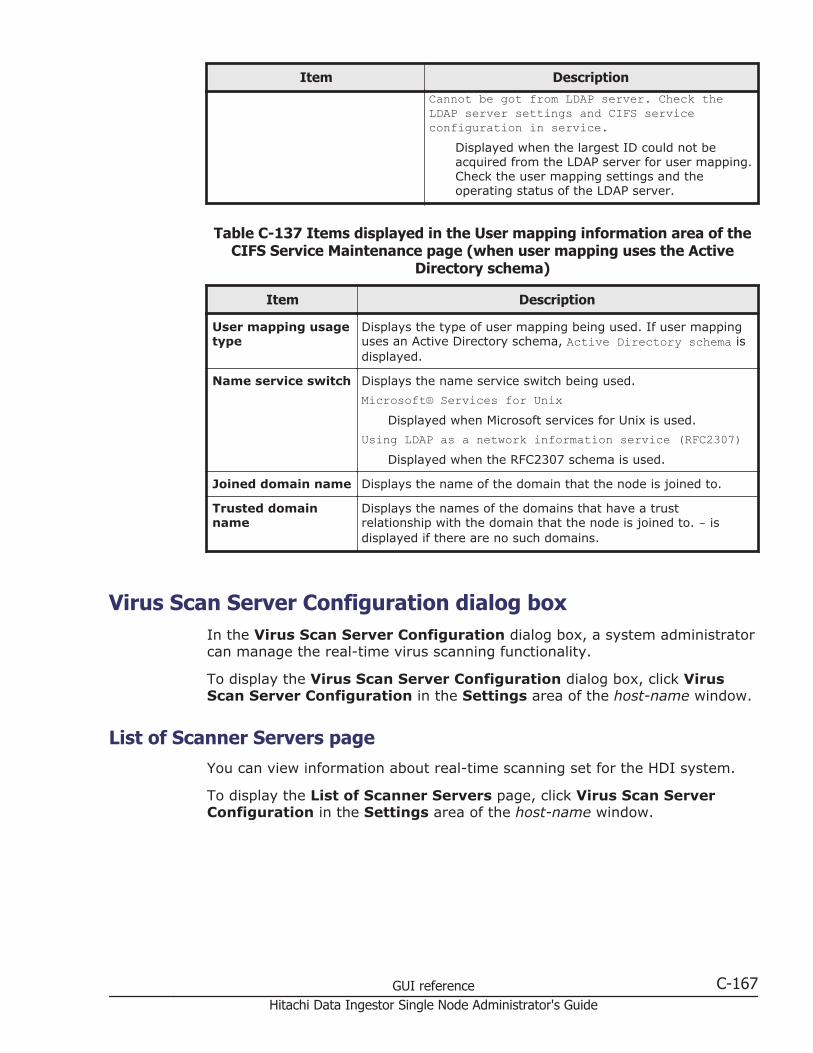
Item DescriptionCannot be got from LDAP server. Check theLDAP server settings and CIFS serviceconfiguration in service.
Displayed when the largest ID could not beacquired from the LDAP server for user mapping.Check the user mapping settings and theoperating status of the LDAP server.
Table C-137 Items displayed in the User mapping information area of theCIFS Service Maintenance page (when user mapping uses the Active
Directory schema)
Item Description
User mapping usagetype
Displays the type of user mapping being used. If user mappinguses an Active Directory schema, Active Directory schema isdisplayed.
Name service switch Displays the name service switch being used.
Microsoft® Services for UnixDisplayed when Microsoft services for Unix is used.
Using LDAP as a network information service (RFC2307)Displayed when the RFC2307 schema is used.
Joined domain name Displays the name of the domain that the node is joined to.
Trusted domainname
Displays the names of the domains that have a trustrelationship with the domain that the node is joined to. - isdisplayed if there are no such domains.
Virus Scan Server Configuration dialog boxIn the Virus Scan Server Configuration dialog box, a system administratorcan manage the real-time virus scanning functionality.
To display the Virus Scan Server Configuration dialog box, click VirusScan Server Configuration in the Settings area of the host-name window.
List of Scanner Servers pageYou can view information about real-time scanning set for the HDI system.
To display the List of Scanner Servers page, click Virus Scan ServerConfiguration in the Settings area of the host-name window.
GUI reference C-167Hitachi Data Ingestor Single Node Administrator's Guide

Table C-138 Items displayed on the in the List of Scanner Servers page
Item Description
Scanning software Displays the name of the scan software that is used. If a scansoftware is not set, - is displayed.
Real-timescanning status
Displays the real-time scanning status.
RunningDisplayed when real-time scanning is enabled.
StoppedDisplayed when real-time scanning is disabled.
Server address Displays either the IP address, domain name, or host name of thescan server. Displays the content of the Server address specifiedin the Add Scanner Server page.
Server status Displays the status of the scan server.
-Displayed when real-time scanning is disabled.
NormalDisplayed when the scan server is functioning normally.
Blocked (Server not found)Displayed when the scan server cannot be found. Make surethat the IP address, domain name, or host name of the scanserver is correct.
Blocked (Access is impossible)Displayed when the port numbers set in the HDI system andthe scan server are different, the real-time virus scan serviceis not available, or the virus scan software specified in theHDI system differs from the software on the scan server.Make sure that the IP address, domain name, or host name ofthe scan server, and the port number of the scan server, arecorrect. Also make sure that ICAP is selected as thecommunication protocol for the scan server, and that the scansoftware is correctly set in the HDI system.
Blocked (Time-out)The scan server timed out. Make sure that no network failurehas occurred.
Blocked (Version conflict)The protocol versions for the HDI system and the scan serverare incompatible. Acquire all the log data, and then informmaintenance personnel.
Blocked (License expired)The license of the scan software installed on the scan serveris invalid. Make sure that the scanning software license hasbeen set up.
Blocked (Scanner server error)A failure occurred in the scan server. Recover the scan serverfrom the failure.
Blocked (Under registration)
C-168 GUI referenceHitachi Data Ingestor Single Node Administrator's Guide

Item Description
Displayed while the information about the registered scanserver is being applied to an HDI system. Wait for severalminutes, and then click Refresh to update the displayedinformation.
Blocked (Invalid protocol)Displayed when the communication protocol is different fromthe one used by Hitachi Server Protect Agent that is installedon the scan server. Check the version of the installed HitachiServer Protect Agent, and then install the correct version.
Blocked (Scanning software is not installed)Displayed when scan software is not installed on the scanserver. Install scan software.
Blocked (Scanning software service has stopped)The service of the scan software on the scan server stopped.Start the service.
Blocked (Access user info. is not registered)Displayed when the information of the user for accessing CIFSshares is not registered on the scan server. Register theinformation.
Blocked (Access user info. is invalid)Displayed when the information of the user for accessing CIFSshares registered on the scan server is incorrect. Correct theinformation.
DeletingDisplayed when operation for deleting the scan server isperformed, but some CIFS clients are using the scan server.The scan server will be deleted when the CIFS clients finishusing the scan server.
Error (System failure)Displayed when a failure occurred in the HDI system, or anattempt to update the status failed. Wait for the timespecified for Server monitoring interval on the ScanConditions page to pass, and then check the status again.
If the status still cannot be updated, acquire all the log data,and then inform maintenance personnel.
Software version Displays the version of the scan software that is installed on thescan server.
If the scan software being used is a Trend Micro product, or if thisinformation cannot be obtained, a hyphen (-) is displayed.
Virus definitionversion
Displays the version of the virus definition file used on the scanserver.
If the scan software being used is a Trend Micro product, or if thisinformation cannot be obtained, a hyphen (-) is displayed.
Edit Server button Edits the information for a scan server. Select the radio button forthe scan server for which you want to change the registeredinformation, and then click the Edit Server button. The EditScanner Server page is displayed (Edit Scanner Server page onpage C-170).
GUI reference C-169Hitachi Data Ingestor Single Node Administrator's Guide
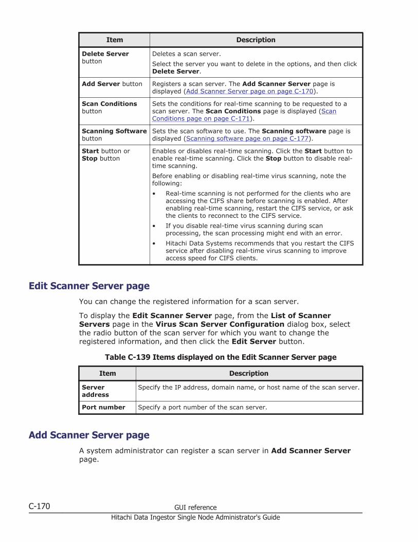
Item Description
Delete Serverbutton
Deletes a scan server.
Select the server you want to delete in the options, and then clickDelete Server.
Add Server button Registers a scan server. The Add Scanner Server page isdisplayed (Add Scanner Server page on page C-170).
Scan Conditionsbutton
Sets the conditions for real-time scanning to be requested to ascan server. The Scan Conditions page is displayed (ScanConditions page on page C-171).
Scanning Softwarebutton
Sets the scan software to use. The Scanning software page isdisplayed (Scanning software page on page C-177).
Start button orStop button
Enables or disables real-time scanning. Click the Start button toenable real-time scanning. Click the Stop button to disable real-time scanning.
Before enabling or disabling real-time virus scanning, note thefollowing:
• Real-time scanning is not performed for the clients who areaccessing the CIFS share before scanning is enabled. Afterenabling real-time scanning, restart the CIFS service, or askthe clients to reconnect to the CIFS service.
• If you disable real-time virus scanning during scanprocessing, the scan processing might end with an error.
• Hitachi Data Systems recommends that you restart the CIFSservice after disabling real-time virus scanning to improveaccess speed for CIFS clients.
Edit Scanner Server pageYou can change the registered information for a scan server.
To display the Edit Scanner Server page, from the List of ScannerServers page in the Virus Scan Server Configuration dialog box, selectthe radio button of the scan server for which you want to change theregistered information, and then click the Edit Server button.
Table C-139 Items displayed on the Edit Scanner Server page
Item Description
Serveraddress
Specify the IP address, domain name, or host name of the scan server.
Port number Specify a port number of the scan server.
Add Scanner Server pageA system administrator can register a scan server in Add Scanner Serverpage.
C-170 GUI referenceHitachi Data Ingestor Single Node Administrator's Guide

To display the Add Scanner Server page, click the Add Server button fromthe List of Scanner Servers page in the Virus Scan Server Configurationdialog box.
Table C-140 Items displayed on the Add Scanner Server page
Item Description
Serveraddress
Specify the IP address, domain name, or host name of the scan server.
Port number Specify a port number of the scan server, from 1024 to 65535.
Add button Registers the scan server.
Scan Conditions pageA system administrator can set scan conditions in Scan Conditions page.
Note:
• The scan server receives a scan request from a node, and then performsreal-time scanning based on the scan server settings. For example, if theextension of a file in the scan request from the node is specified not to bescanned for the scan server, real-time scanning is not performed. Fordetails about the scan server environment settings and scanning softwaresettings, see the Installation and Configuration Guide.
• For details about how to remove files and paths in a CIFS share asscanning targets, see the CLI Administrator's Guide.
To display the Scan Conditions page, click the Scan Conditions buttonfrom the List of Scanner Servers page in the Virus Scan ServerConfiguration dialog box.
Table C-141 Items displayed on the Scan Conditions page
Item Description
Scan timing Select the timing of scans in the options.
Read and write
Executes a scan when the CIFS client hasread or written files.
Read only
Executes a scan when the CIFS client hasread files.
Write only
Executes a scan when the CIFS client haswritten files.
Extension for scanning Select the files to be scanned in the options.However, this item might not be displayeddepending on the scan software in use.
Scan all files regardless of extension
Scans all the files for viruses.
GUI reference C-171Hitachi Data Ingestor Single Node Administrator's Guide
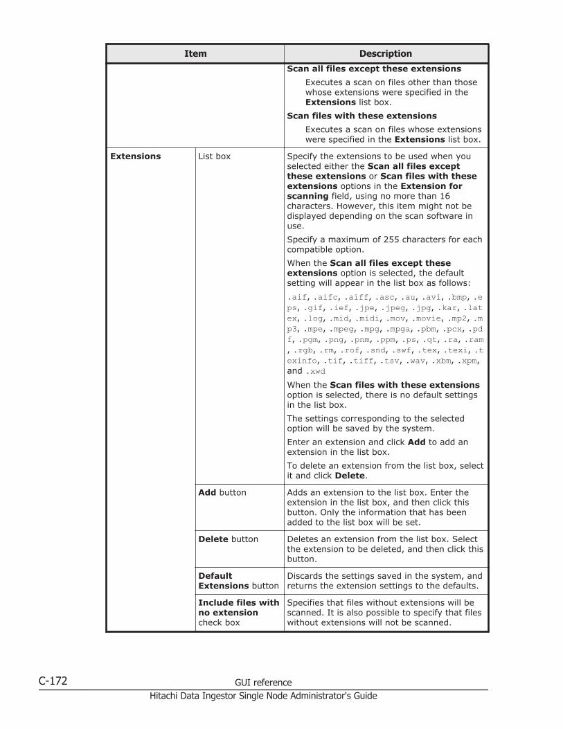
Item Description
Scan all files except these extensions
Executes a scan on files other than thosewhose extensions were specified in theExtensions list box.
Scan files with these extensions
Executes a scan on files whose extensionswere specified in the Extensions list box.
Extensions List box Specify the extensions to be used when youselected either the Scan all files exceptthese extensions or Scan files with theseextensions options in the Extension forscanning field, using no more than 16characters. However, this item might not bedisplayed depending on the scan software inuse.
Specify a maximum of 255 characters for eachcompatible option.
When the Scan all files except theseextensions option is selected, the defaultsetting will appear in the list box as follows:
.aif, .aifc, .aiff, .asc, .au, .avi, .bmp, .eps, .gif, .ief, .jpe, .jpeg, .jpg, .kar, .latex, .log, .mid, .midi, .mov, .movie, .mp2, .mp3, .mpe, .mpeg, .mpg, .mpga, .pbm, .pcx, .pdf, .pgm, .png, .pnm, .ppm, .ps, .qt, .ra, .ram, .rgb, .rm, .rof, .snd, .swf, .tex, .texi, .texinfo, .tif, .tiff, .tsv, .wav, .xbm, .xpm,and .xwdWhen the Scan files with these extensionsoption is selected, there is no default settingsin the list box.
The settings corresponding to the selectedoption will be saved by the system.
Enter an extension and click Add to add anextension in the list box.
To delete an extension from the list box, selectit and click Delete.
Add button Adds an extension to the list box. Enter theextension in the list box, and then click thisbutton. Only the information that has beenadded to the list box will be set.
Delete button Deletes an extension from the list box. Selectthe extension to be deleted, and then click thisbutton.
DefaultExtensions button
Discards the settings saved in the system, andreturns the extension settings to the defaults.
Include files withno extensioncheck box
Specifies that files without extensions will bescanned. It is also possible to specify that fileswithout extensions will not be scanned.
C-172 GUI referenceHitachi Data Ingestor Single Node Administrator's Guide
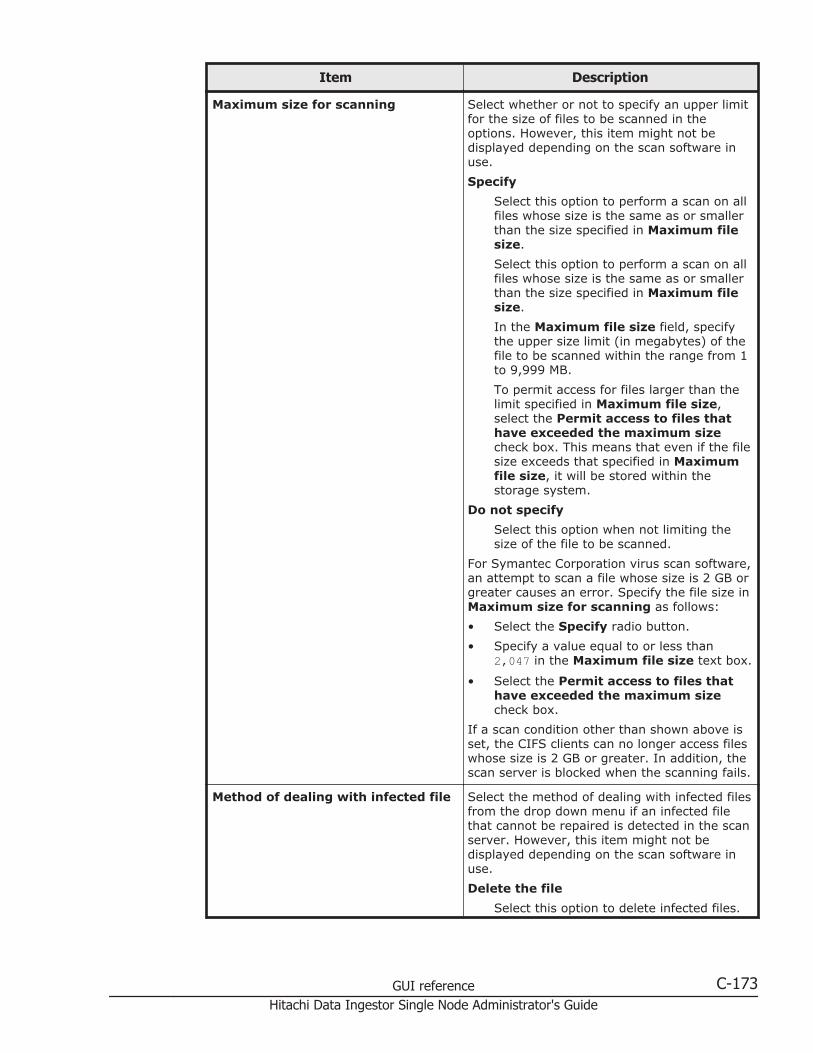
Item Description
Maximum size for scanning Select whether or not to specify an upper limitfor the size of files to be scanned in theoptions. However, this item might not bedisplayed depending on the scan software inuse.
Specify
Select this option to perform a scan on allfiles whose size is the same as or smallerthan the size specified in Maximum filesize.
Select this option to perform a scan on allfiles whose size is the same as or smallerthan the size specified in Maximum filesize.
In the Maximum file size field, specifythe upper size limit (in megabytes) of thefile to be scanned within the range from 1to 9,999 MB.
To permit access for files larger than thelimit specified in Maximum file size,select the Permit access to files thathave exceeded the maximum sizecheck box. This means that even if the filesize exceeds that specified in Maximumfile size, it will be stored within thestorage system.
Do not specify
Select this option when not limiting thesize of the file to be scanned.
For Symantec Corporation virus scan software,an attempt to scan a file whose size is 2 GB orgreater causes an error. Specify the file size inMaximum size for scanning as follows:
• Select the Specify radio button.
• Specify a value equal to or less than2,047 in the Maximum file size text box.
• Select the Permit access to files thathave exceeded the maximum sizecheck box.
If a scan condition other than shown above isset, the CIFS clients can no longer access fileswhose size is 2 GB or greater. In addition, thescan server is blocked when the scanning fails.
Method of dealing with infected file Select the method of dealing with infected filesfrom the drop down menu if an infected filethat cannot be repaired is detected in the scanserver. However, this item might not bedisplayed depending on the scan software inuse.
Delete the file
Select this option to delete infected files.
GUI reference C-173Hitachi Data Ingestor Single Node Administrator's Guide
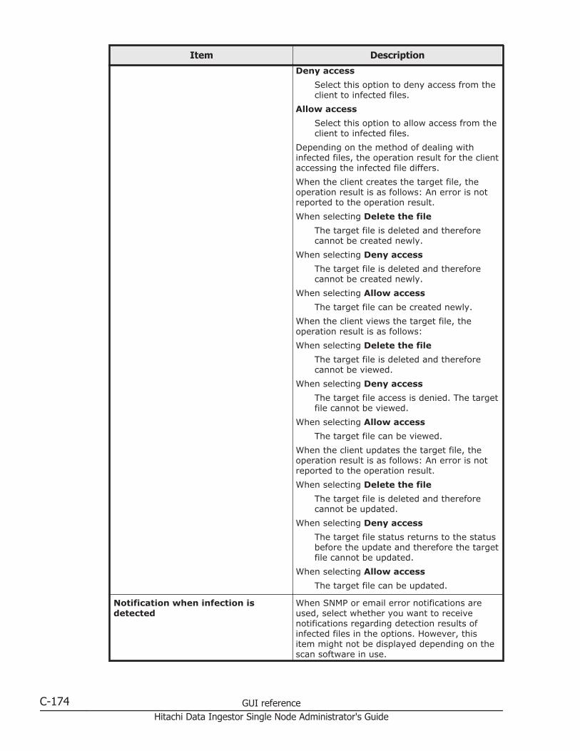
Item Description
Deny access
Select this option to deny access from theclient to infected files.
Allow access
Select this option to allow access from theclient to infected files.
Depending on the method of dealing withinfected files, the operation result for the clientaccessing the infected file differs.
When the client creates the target file, theoperation result is as follows: An error is notreported to the operation result.
When selecting Delete the file
The target file is deleted and thereforecannot be created newly.
When selecting Deny access
The target file is deleted and thereforecannot be created newly.
When selecting Allow access
The target file can be created newly.
When the client views the target file, theoperation result is as follows:
When selecting Delete the file
The target file is deleted and thereforecannot be viewed.
When selecting Deny access
The target file access is denied. The targetfile cannot be viewed.
When selecting Allow access
The target file can be viewed.
When the client updates the target file, theoperation result is as follows: An error is notreported to the operation result.
When selecting Delete the file
The target file is deleted and thereforecannot be updated.
When selecting Deny access
The target file status returns to the statusbefore the update and therefore the targetfile cannot be updated.
When selecting Allow access
The target file can be updated.
Notification when infection isdetected
When SNMP or email error notifications areused, select whether you want to receivenotifications regarding detection results ofinfected files in the options. However, thisitem might not be displayed depending on thescan software in use.
C-174 GUI referenceHitachi Data Ingestor Single Node Administrator's Guide
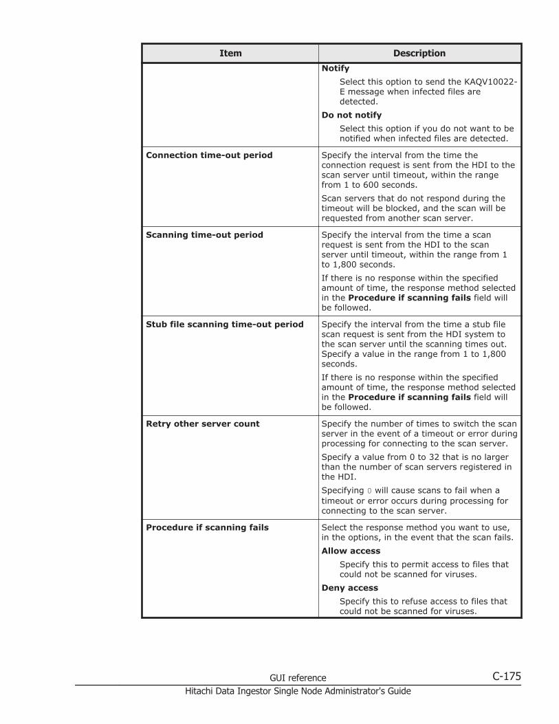
Item Description
Notify
Select this option to send the KAQV10022-E message when infected files aredetected.
Do not notify
Select this option if you do not want to benotified when infected files are detected.
Connection time-out period Specify the interval from the time theconnection request is sent from the HDI to thescan server until timeout, within the rangefrom 1 to 600 seconds.
Scan servers that do not respond during thetimeout will be blocked, and the scan will berequested from another scan server.
Scanning time-out period Specify the interval from the time a scanrequest is sent from the HDI to the scanserver until timeout, within the range from 1to 1,800 seconds.
If there is no response within the specifiedamount of time, the response method selectedin the Procedure if scanning fails field willbe followed.
Stub file scanning time-out period Specify the interval from the time a stub filescan request is sent from the HDI system tothe scan server until the scanning times out.Specify a value in the range from 1 to 1,800seconds.
If there is no response within the specifiedamount of time, the response method selectedin the Procedure if scanning fails field willbe followed.
Retry other server count Specify the number of times to switch the scanserver in the event of a timeout or error duringprocessing for connecting to the scan server.
Specify a value from 0 to 32 that is no largerthan the number of scan servers registered inthe HDI.
Specifying 0 will cause scans to fail when atimeout or error occurs during processing forconnecting to the scan server.
Procedure if scanning fails Select the response method you want to use,in the options, in the event that the scan fails.
Allow access
Specify this to permit access to files thatcould not be scanned for viruses.
Deny access
Specify this to refuse access to files thatcould not be scanned for viruses.
GUI reference C-175Hitachi Data Ingestor Single Node Administrator's Guide
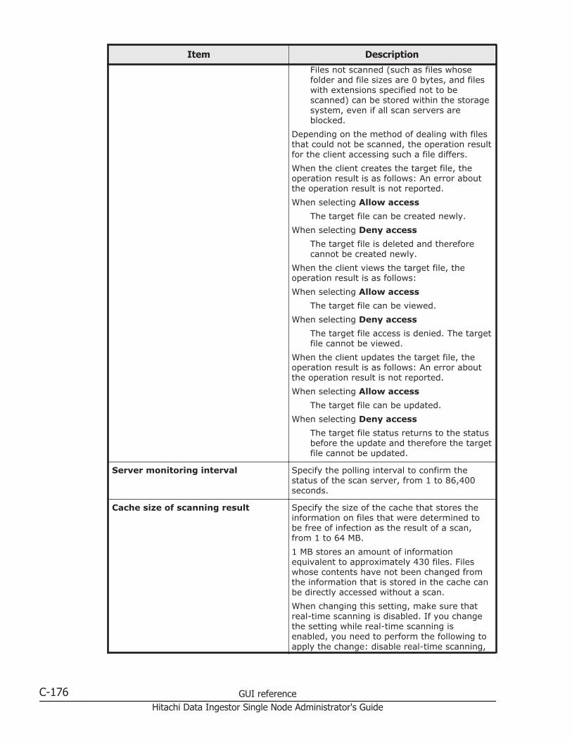
Item Description
Files not scanned (such as files whosefolder and file sizes are 0 bytes, and fileswith extensions specified not to bescanned) can be stored within the storagesystem, even if all scan servers areblocked.
Depending on the method of dealing with filesthat could not be scanned, the operation resultfor the client accessing such a file differs.
When the client creates the target file, theoperation result is as follows: An error aboutthe operation result is not reported.
When selecting Allow access
The target file can be created newly.
When selecting Deny access
The target file is deleted and thereforecannot be created newly.
When the client views the target file, theoperation result is as follows:
When selecting Allow access
The target file can be viewed.
When selecting Deny access
The target file access is denied. The targetfile cannot be viewed.
When the client updates the target file, theoperation result is as follows: An error aboutthe operation result is not reported.
When selecting Allow access
The target file can be updated.
When selecting Deny access
The target file status returns to the statusbefore the update and therefore the targetfile cannot be updated.
Server monitoring interval Specify the polling interval to confirm thestatus of the scan server, from 1 to 86,400seconds.
Cache size of scanning result Specify the size of the cache that stores theinformation on files that were determined tobe free of infection as the result of a scan,from 1 to 64 MB.
1 MB stores an amount of informationequivalent to approximately 430 files. Fileswhose contents have not been changed fromthe information that is stored in the cache canbe directly accessed without a scan.
When changing this setting, make sure thatreal-time scanning is disabled. If you changethe setting while real-time scanning isenabled, you need to perform the following toapply the change: disable real-time scanning,
C-176 GUI referenceHitachi Data Ingestor Single Node Administrator's Guide
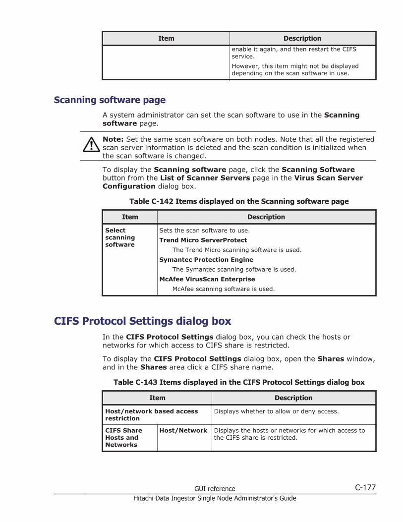
Item Description
enable it again, and then restart the CIFSservice.
However, this item might not be displayeddepending on the scan software in use.
Scanning software pageA system administrator can set the scan software to use in the Scanningsoftware page.
Note: Set the same scan software on both nodes. Note that all the registeredscan server information is deleted and the scan condition is initialized whenthe scan software is changed.
To display the Scanning software page, click the Scanning Softwarebutton from the List of Scanner Servers page in the Virus Scan ServerConfiguration dialog box.
Table C-142 Items displayed on the Scanning software page
Item Description
Selectscanningsoftware
Sets the scan software to use.
Trend Micro ServerProtect
The Trend Micro scanning software is used.
Symantec Protection Engine
The Symantec scanning software is used.
McAfee VirusScan Enterprise
McAfee scanning software is used.
CIFS Protocol Settings dialog boxIn the CIFS Protocol Settings dialog box, you can check the hosts ornetworks for which access to CIFS share is restricted.
To display the CIFS Protocol Settings dialog box, open the Shares window,and in the Shares area click a CIFS share name.
Table C-143 Items displayed in the CIFS Protocol Settings dialog box
Item Description
Host/network based accessrestriction
Displays whether to allow or deny access.
CIFS ShareHosts andNetworks
Host/Network Displays the hosts or networks for which access tothe CIFS share is restricted.
GUI reference C-177Hitachi Data Ingestor Single Node Administrator's Guide

Item Description
Accesspermissions
New files Displays the access permissions of Owner, Group,and Other (all users and groups) for creating files ina CIFS share.
RWPermit read-write access.
ROPermit read-only access.
NoneDo not permit read or write access.
Displays -- if the Access permissions setting ofthe CIFS share is set to Owner only. DisplaysUnknown if the ACL type of the file system cannot beacquired.
Newdirectories
Displays the access permissions of Owner, Group,and Other (all users and groups) for creatingdirectories in a CIFS share.
RWPermit read-write access.
ROPermit read-only access.
NoneDo not permit read or write access.
Displays -- if the Access permissions setting ofthe CIFS share is set to Owner only. DisplaysUnknown if the ACL type of the file system cannot beacquired.
NFS Protocol Settings dialog boxYou can check the hosts and networks that can access NFS shares.
To display the NFS Protocol Settings dialog box, display the Shareswindow, and then, in the Shares area, click the absolute path to the shareddirectory.
Table C-144 Items displayed in the NFS Protocol Settings dialog box
Item Description
NFS ShareHosts andNetworks
Host/Network Displays the hosts and networks that can access NFSshares.
AnonymousMapping
Displays the users who access the HDI system fromthe hosts and networks that can access NFS shares,specified in Host/Network, and are mapped asanonymous users.
C-178 GUI referenceHitachi Data Ingestor Single Node Administrator's Guide
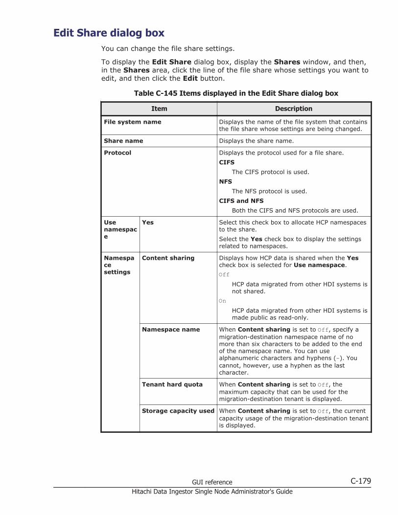
Edit Share dialog boxYou can change the file share settings.
To display the Edit Share dialog box, display the Shares window, and then,in the Shares area, click the line of the file share whose settings you want toedit, and then click the Edit button.
Table C-145 Items displayed in the Edit Share dialog box
Item Description
File system name Displays the name of the file system that containsthe file share whose settings are being changed.
Share name Displays the share name.
Protocol Displays the protocol used for a file share.
CIFS
The CIFS protocol is used.
NFS
The NFS protocol is used.
CIFS and NFS
Both the CIFS and NFS protocols are used.
Usenamespace
Yes Select this check box to allocate HCP namespacesto the share.
Select the Yes check box to display the settingsrelated to namespaces.
Namespacesettings
Content sharing Displays how HCP data is shared when the Yescheck box is selected for Use namespace.
OffHCP data migrated from other HDI systems isnot shared.
OnHCP data migrated from other HDI systems ismade public as read-only.
Namespace name When Content sharing is set to Off, specify amigration-destination namespace name of nomore than six characters to be added to the endof the namespace name. You can usealphanumeric characters and hyphens (-). Youcannot, however, use a hyphen as the lastcharacter.
Tenant hard quota When Content sharing is set to Off, themaximum capacity that can be used for themigration-destination tenant is displayed.
Storage capacity used When Content sharing is set to Off, the currentcapacity usage of the migration-destination tenantis displayed.
GUI reference C-179Hitachi Data Ingestor Single Node Administrator's Guide
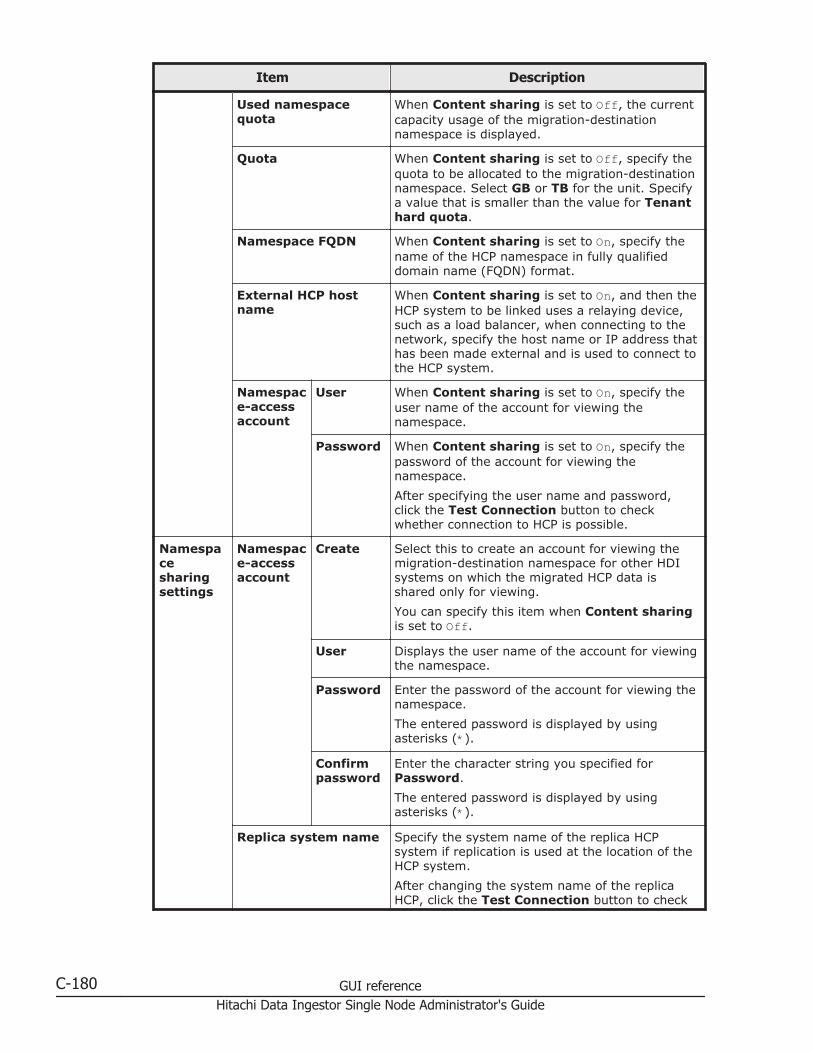
Item Description
Used namespacequota
When Content sharing is set to Off, the currentcapacity usage of the migration-destinationnamespace is displayed.
Quota When Content sharing is set to Off, specify thequota to be allocated to the migration-destinationnamespace. Select GB or TB for the unit. Specifya value that is smaller than the value for Tenanthard quota.
Namespace FQDN When Content sharing is set to On, specify thename of the HCP namespace in fully qualifieddomain name (FQDN) format.
External HCP hostname
When Content sharing is set to On, and then theHCP system to be linked uses a relaying device,such as a load balancer, when connecting to thenetwork, specify the host name or IP address thathas been made external and is used to connect tothe HCP system.
Namespace-accessaccount
User When Content sharing is set to On, specify theuser name of the account for viewing thenamespace.
Password When Content sharing is set to On, specify thepassword of the account for viewing thenamespace.
After specifying the user name and password,click the Test Connection button to checkwhether connection to HCP is possible.
Namespacesharingsettings
Namespace-accessaccount
Create Select this to create an account for viewing themigration-destination namespace for other HDIsystems on which the migrated HCP data isshared only for viewing.
You can specify this item when Content sharingis set to Off.
User Displays the user name of the account for viewingthe namespace.
Password Enter the password of the account for viewing thenamespace.
The entered password is displayed by usingasterisks (*).
Confirmpassword
Enter the character string you specified forPassword.
The entered password is displayed by usingasterisks (*).
Replica system name Specify the system name of the replica HCPsystem if replication is used at the location of theHCP system.
After changing the system name of the replicaHCP, click the Test Connection button to check
C-180 GUI referenceHitachi Data Ingestor Single Node Administrator's Guide
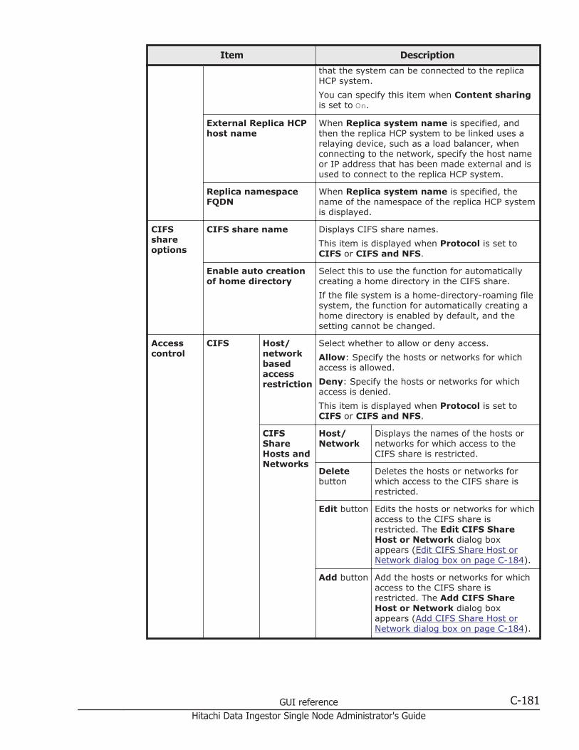
Item Description
that the system can be connected to the replicaHCP system.
You can specify this item when Content sharingis set to On.
External Replica HCPhost name
When Replica system name is specified, andthen the replica HCP system to be linked uses arelaying device, such as a load balancer, whenconnecting to the network, specify the host nameor IP address that has been made external and isused to connect to the replica HCP system.
Replica namespaceFQDN
When Replica system name is specified, thename of the namespace of the replica HCP systemis displayed.
CIFSshareoptions
CIFS share name Displays CIFS share names.
This item is displayed when Protocol is set toCIFS or CIFS and NFS.
Enable auto creationof home directory
Select this to use the function for automaticallycreating a home directory in the CIFS share.
If the file system is a home-directory-roaming filesystem, the function for automatically creating ahome directory is enabled by default, and thesetting cannot be changed.
Accesscontrol
CIFS Host/networkbasedaccessrestriction
Select whether to allow or deny access.
Allow: Specify the hosts or networks for whichaccess is allowed.
Deny: Specify the hosts or networks for whichaccess is denied.
This item is displayed when Protocol is set toCIFS or CIFS and NFS.
CIFSShareHosts andNetworks
Host/Network
Displays the names of the hosts ornetworks for which access to theCIFS share is restricted.
Deletebutton
Deletes the hosts or networks forwhich access to the CIFS share isrestricted.
Edit button Edits the hosts or networks for whichaccess to the CIFS share isrestricted. The Edit CIFS ShareHost or Network dialog boxappears (Edit CIFS Share Host orNetwork dialog box on page C-184).
Add button Add the hosts or networks for whichaccess to the CIFS share isrestricted. The Add CIFS ShareHost or Network dialog boxappears (Add CIFS Share Host orNetwork dialog box on page C-184).
GUI reference C-181Hitachi Data Ingestor Single Node Administrator's Guide
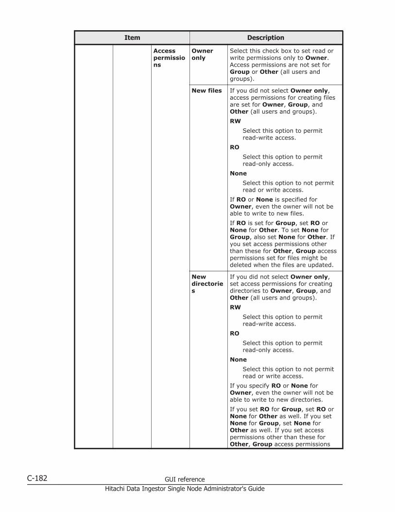
Item Description
Accesspermissions
Owneronly
Select this check box to set read orwrite permissions only to Owner.Access permissions are not set forGroup or Other (all users andgroups).
New files If you did not select Owner only,access permissions for creating filesare set for Owner, Group, andOther (all users and groups).
RW
Select this option to permitread-write access.
RO
Select this option to permitread-only access.
None
Select this option to not permitread or write access.
If RO or None is specified forOwner, even the owner will not beable to write to new files.
If RO is set for Group, set RO orNone for Other. To set None forGroup, also set None for Other. Ifyou set access permissions otherthan these for Other, Group accesspermissions set for files might bedeleted when the files are updated.
Newdirectories
If you did not select Owner only,set access permissions for creatingdirectories to Owner, Group, andOther (all users and groups).
RW
Select this option to permitread-write access.
RO
Select this option to permitread-only access.
None
Select this option to not permitread or write access.
If you specify RO or None forOwner, even the owner will not beable to write to new directories.
If you set RO for Group, set RO orNone for Other as well. If you setNone for Group, set None forOther as well. If you set accesspermissions other than these forOther, Group access permissions
C-182 GUI referenceHitachi Data Ingestor Single Node Administrator's Guide

Item Description
set for directories might be deletedwhen the directories are updated.
NFS NFS ShareHosts andNetworks
Host/Network
Displays the hosts and networks thatcan access the NFS share.
This item is displayed when Protocolis set to NFS or CIFS and NFS.
AnonymousMapping
Displays the users who access theHDI system from the hosts andnetworks that can access NFSshares, specified in Host/Network,and are mapped as anonymoususers.
Deletebutton
Deletes an object that can access theNFS share.
Edit button Displays the Edit NFS Share Hostor Network dialog box that can beused to edit the objects that canaccess an NFS share (Edit NFS ShareHost or Network dialog box on pageC-185).
Add button Displays the Add NFS Share Hostor Network dialog box that can beused to add an object that canaccess the NFS share (Add NFSShare Host or Network dialog box onpage C-186).
Release Share(s) dialog boxYou can release file system shares.
To display the Release Share(s) dialog box, display the Shares window,and then, in the Shares area, click the line for the file share to be released,and then click the Release button.
Table C-146 Items displayed in the Release Share(s) dialog box
Item Description
Shares Share Name Displays the share name.
Protocol Displays the protocol used for the file share.
File SystemName
Displays the name of the file system for which thefile share was created.
Apply button Releases the file share.
GUI reference C-183Hitachi Data Ingestor Single Node Administrator's Guide
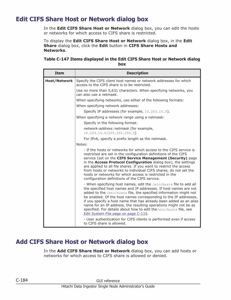
Edit CIFS Share Host or Network dialog boxIn the Edit CIFS Share Host or Network dialog box, you can edit the hostsor networks for which access to CIFS share is restricted.
To display the Edit CIFS Share Host or Network dialog box, in the EditShare dialog box, click the Edit button in CIFS Share Hosts andNetworks.
Table C-147 Items displayed in the Edit CIFS Share Host or Network dialogbox
Item Description
Host/Network Specify the CIFS client host names or network addresses for whichaccess to the CIFS share is to be restricted.
Use no more than 5,631 characters. When specifying networks, youcan also use a netmask.
When specifying networks, use either of the following formats:
When specifying network addresses:
Specify IP addresses (for example, 10.203.15.0).
When specifying a network range using a netmask:
Specify in the following format:
network-address/netmask (for example,10.203.15.0/255.255.255.0)
For IPv6, specify a prefix length as the netmask.
Notes:
- If the hosts or networks for which access to the CIFS service isrestricted are set in the configuration definitions of the CIFSservice (set on the CIFS Service Management (Security) pagein the Access Protocol Configuration dialog box), the settingsare applied to all file shares. If you want to restrict the accessfrom hosts or networks to individual CIFS shares, do not set thehosts or networks for which access is restricted in theconfiguration definitions of the CIFS service.
- When specifying host names, edit the /etc/hosts file to add allthe specified host names and IP addresses. If host names are notadded to the /etc/hosts file, the specified information might notbe enabled. Of the host names corresponding to the IP addresses,if you specify a host name that has already been added as an aliasname for an IP address, the resulting operations might not be asspecified. For details about how to edit the/etc/hosts file, seeEdit System File page on page C-115.
- User authentication for CIFS clients is performed even if accessto CIFS share is allowed.
Add CIFS Share Host or Network dialog boxIn the Add CIFS Share Host or Network dialog box, you can add hosts ornetworks for which access to CIFS share is allowed or denied.
C-184 GUI referenceHitachi Data Ingestor Single Node Administrator's Guide
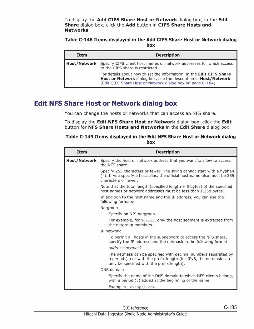
To display the Add CIFS Share Host or Network dialog box, in the EditShare dialog box, click the Add button in CIFS Share Hosts andNetworks.
Table C-148 Items displayed in the Add CIFS Share Host or Network dialogbox
Item Description
Host/Network Specify CIFS client host names or network addresses for which accessto the CIFS share is restricted.
For details about how to set the information, in the Edit CIFS ShareHost or Network dialog box, see the description in Host/Network(Edit CIFS Share Host or Network dialog box on page C-184).
Edit NFS Share Host or Network dialog boxYou can change the hosts or networks that can access an NFS share.
To display the Edit NFS Share Host or Network dialog box, click the Editbutton for NFS Share Hosts and Networks in the Edit Share dialog box.
Table C-149 Items displayed in the Edit NFS Share Host or Network dialogbox
Item Description
Host/Network Specify the host or network address that you want to allow to accessthe NFS share.
Specify 255 characters or fewer. The string cannot start with a hyphen(-). If you specify a host alias, the official host name also must be 255characters or fewer.
Note that the total length (specified length + 5 bytes) of the specifiedhost names or network addresses must be less than 1,258 bytes.
In addition to the host name and the IP address, you can use thefollowing formats:
Netgroup
Specify an NIS netgroup.
For example, for @group, only the host segment is extracted fromthe netgroup members.
IP network
To permit all hosts in the subnetwork to access the NFS share,specify the IP address and the netmask in the following format:
address/netmask
The netmask can be specified with decimal numbers separated bya period (.) or with the prefix length (for IPv6, the netmask canonly be specified with the prefix length).
DNS domain
Specify the name of the DNS domain to which NFS clients belong,with a period (.) added at the beginning of the name.
Example: .example.com
GUI reference C-185Hitachi Data Ingestor Single Node Administrator's Guide
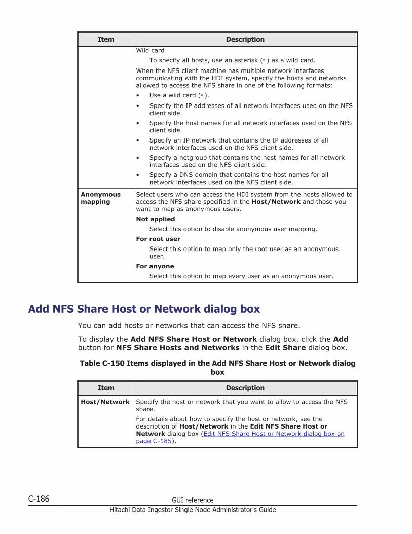
Item Description
Wild card
To specify all hosts, use an asterisk (*) as a wild card.
When the NFS client machine has multiple network interfacescommunicating with the HDI system, specify the hosts and networksallowed to access the NFS share in one of the following formats:
• Use a wild card (*).
• Specify the IP addresses of all network interfaces used on the NFSclient side.
• Specify the host names for all network interfaces used on the NFSclient side.
• Specify an IP network that contains the IP addresses of allnetwork interfaces used on the NFS client side.
• Specify a netgroup that contains the host names for all networkinterfaces used on the NFS client side.
• Specify a DNS domain that contains the host names for allnetwork interfaces used on the NFS client side.
Anonymousmapping
Select users who can access the HDI system from the hosts allowed toaccess the NFS share specified in the Host/Network and those youwant to map as anonymous users.
Not applied
Select this option to disable anonymous user mapping.
For root user
Select this option to map only the root user as an anonymoususer.
For anyone
Select this option to map every user as an anonymous user.
Add NFS Share Host or Network dialog boxYou can add hosts or networks that can access the NFS share.
To display the Add NFS Share Host or Network dialog box, click the Addbutton for NFS Share Hosts and Networks in the Edit Share dialog box.
Table C-150 Items displayed in the Add NFS Share Host or Network dialogbox
Item Description
Host/Network Specify the host or network that you want to allow to access the NFSshare.
For details about how to specify the host or network, see thedescription of Host/Network in the Edit NFS Share Host orNetwork dialog box (Edit NFS Share Host or Network dialog box onpage C-185).
C-186 GUI referenceHitachi Data Ingestor Single Node Administrator's Guide

Item Description
Anonymousmapping
Select users who can access the HDI system from the hosts allowed toaccess the NFS share specified in the Host/Network and those youwant to map as anonymous users.
Not applied
Select this option to disable anonymous user mapping.
For root user
Select this option to map only the root user as an anonymoususer.
For anyone
Select this option to map every user as an anonymous user.
Add Share dialog boxYou can add a file share in the file system.
A maximum of 1,024 NFS shares can be created.
The maximum number of CIFS shares varies depending on whether theconfiguration definition of the CIFS service is set so that the settings on CIFSshares are automatically reloaded and applied to the CIFS client environment.For details about the maximum number of CIFS shares, see the File SystemProtocols (CIFS/NFS) Administrator's Guide.
To display the Add Share dialog box, display the File Systems window, andthen, in the File Systems tab, select the line for the file system in which youwant to add a file share, and then click the Add Share button.
Table C-151 Items displayed in the Add Share dialog box
Item Description
File system name Displays the name of the file system to which afile share is being added.
Share directory Specifies the shared directory name.
This item is not displayed if you create a home-directory-roaming file system. The mount point isautomatically specified as the shared directory.
Share name Displays the share name.
Protocol Specifies the protocol to be used for the file sharebeing added.
CIFS
The CIFS protocol will be used.
NFS
The NFS protocol will be used.
CIFS and NFS
Both the CIFS and NFS protocols will be used.
GUI reference C-187Hitachi Data Ingestor Single Node Administrator's Guide

Item Description
If you create a file share in a home-directory-roaming file system, CIFS is specifiedautomatically.
Directoryto use
Use existing directoryas is
Select this to use an existing directory as ashared directory without changing any permissionsettings.
If you create a file share in a home-directory-roaming file system, this item is not displayedbecause the mount point is specified as theshared directory.
Create directory Select this to create a new directory as a shareddirectory or to change the permission settings ofthe existing directory that is to be used as ashared directory. If this item is selected, root isset as the user and group names.
If you create a file share in a home-directory-roaming file system, this item is not displayedbecause the mount point is specified as theshared directory.
Usenamespace
Yes Select this check box to add a file share directlybelow the mount point for the file system, andthen allocate the HCP namespace to the fileshare.
Select the Yes check box to display the settingsrelated to namespaces.
Namespacesettings
Content sharing Displays how HCP data is shared when the Yescheck box is selected for Use namespace.
OffHCP data migrated from other HDI systems isnot shared.
OnHCP data migrated from other HDI systems ismade public as read-only.
Namespace name When Content sharing is set to Off, specify amigration-destination namespace name of nomore than six characters to be added to the endof the namespace name. You can usealphanumeric characters and hyphens (-). Youcannot, however, use a hyphen as the lastcharacter.
Tenant hard quota When Content sharing is set to Off, themaximum capacity that can be used for themigration-destination tenant is displayed.
Storage capacity used When Content sharing is set to Off, the currentcapacity usage of the migration-destination tenantis displayed.
Quota When Content sharing is set to Off, specify thequota to be assigned to the migration-destinationnamespace. Specify the quota to be assigned to
C-188 GUI referenceHitachi Data Ingestor Single Node Administrator's Guide

Item Description
the namespace in GB or TB units. Specify a valuethat is smaller than the value for Tenant hardquota.
Namespace FQDN When Content sharing is set to On, specify thename of the HCP namespace in fully qualifieddomain name (FQDN) format.
External HCP hostname
When Content sharing is set to On, and then theHCP system to be linked uses a relaying device,such as a load balancer, when connecting to thenetwork, specify the host name or IP address thathas been made external and is used to connect tothe HCP system.
Namespace-accessaccount
User When Content sharing is set to On, specify theuser name of the account used to view thenamespace.
Password When Content sharing is set to On, specify thepassword of the account for viewing thenamespace.
After specifying the user name and password,click the Test Connection button to checkwhether connection to HCP is possible.
Namespacesharingsettings
Namespace-accessaccount
Create Select this to create an account for viewing themigration-destination namespace for other HDIsystems on which the migrated HCP data isshared only for viewing.
You can specify this item when Content sharingis set to Off.
User Displays the user name of the account for viewingthe namespace.
Password Enter the password of the account for viewing thenamespace.
The entered password is displayed by usingasterisks (*).
Confirmpassword
Enter the character string you specified forPassword.
The entered password is displayed by usingasterisks (*).
Replica system name Specify the system name of the replica HCPsystem if replication is used at the location of theHCP system.
After changing the system name of the replicaHCP, click the Test Connection button to checkthat the system can be connected to the replicaHCP system.
You can specify this item when Content sharingis set to On.
External Replica HCPhost name
When Replica system name is specified, andthen the replica HCP system to be linked uses a
GUI reference C-189Hitachi Data Ingestor Single Node Administrator's Guide

Item Description
relaying device, such as a load balancer, whenconnecting to the network, specify the host nameor IP address that has been made external and isused to connect to the replica HCP system.
Replica namespaceFQDN
When Replica system name is specified, thename of the namespace of the replica HCP systemis displayed.
CIFSshareoptions
CIFS share name Specify the CIFS share name.
This item is displayed if either CIFS or CIFS andNFS is selected for Protocol.
Enable auto creationof home directory
Select this to use the function for automaticallycreating a home directory in the CIFS share.
If you create a file share in a home-directory-roaming file system, the function for automaticallycreating a home directory is enabled by default,and the setting cannot be changed.
Accesscontrol
CIFS Host/networkbasedaccessrestriction
Select whether to allow or deny access.
Allow: Specify the hosts or networks for whichaccess is allowed.
Deny: Specify the hosts or networks for whichaccess is denied.
This item is displayed when CIFS or CIFS andNFS is selected for the Protocol.
CIFSShareHosts andNetworks
Host/Network
Displays the names of hosts ornetworks for which access to theCIFS share is restricted.
Deletebutton
Delete the hosts or networks forwhich access to the CIFS share isrestricted.
Edit button Displays the Edit CIFS Share Hostor Network dialog box that can beused to edit the hosts or networksfor which access to the CIFS share isrestricted (Edit CIFS Share Host orNetwork dialog box on page C-184).
Add button Displays the Add CIFS Share Hostor Network dialog box that can beused to add hosts or networks forwhich access to the CIFS share isrestricted (Add CIFS Share Host orNetwork dialog box on page C-184).
Accesspermissions
Owneronly
Select this check box to set read orwrite permissions only to Owner.Access permissions are not set forGroup or Other (all users andgroups).
New files If you did not select Owner only,access permissions for creating files
C-190 GUI referenceHitachi Data Ingestor Single Node Administrator's Guide
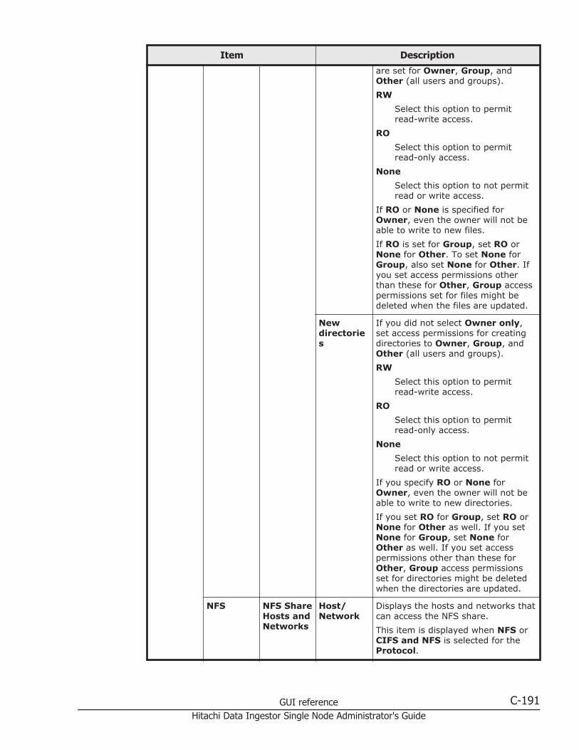
Item Description
are set for Owner, Group, andOther (all users and groups).
RW
Select this option to permitread-write access.
RO
Select this option to permitread-only access.
None
Select this option to not permitread or write access.
If RO or None is specified forOwner, even the owner will not beable to write to new files.
If RO is set for Group, set RO orNone for Other. To set None forGroup, also set None for Other. Ifyou set access permissions otherthan these for Other, Group accesspermissions set for files might bedeleted when the files are updated.
Newdirectories
If you did not select Owner only,set access permissions for creatingdirectories to Owner, Group, andOther (all users and groups).
RW
Select this option to permitread-write access.
RO
Select this option to permitread-only access.
None
Select this option to not permitread or write access.
If you specify RO or None forOwner, even the owner will not beable to write to new directories.
If you set RO for Group, set RO orNone for Other as well. If you setNone for Group, set None forOther as well. If you set accesspermissions other than these forOther, Group access permissionsset for directories might be deletedwhen the directories are updated.
NFS NFS ShareHosts andNetworks
Host/Network
Displays the hosts and networks thatcan access the NFS share.
This item is displayed when NFS orCIFS and NFS is selected for theProtocol.
GUI reference C-191Hitachi Data Ingestor Single Node Administrator's Guide

Item Description
AnonymousMapping
Displays the users who access theHDI system from the hosts andnetworks that can access NFSshares, specified in Host/Network,and are mapped as anonymoususers.
Deletebutton
Deletes an object that can accessthe NFS share.
Edit button Displays the Edit NFS Share Hostor Network dialog box that can beused to change the objects that canaccess the NFS share (Edit NFSShare Host or Network dialog box onpage C-185).
Add button Displays the Add NFS Share Hostor Network dialog box that can beused to add an object that canaccess the NFS share (Add NFSShare Host or Network dialog box onpage C-186).
Directory ACL type Displays the ACL type of the file system.
Advanced ACLThe ACL type is Advanced ACL.
Classic ACLThe ACL type is Classic ACL.
This item is displayed when Create directory isselected for Directory to use.
ACLRegistered UsersandGroups
Type Displays the type of the target useror group.
Items related to ACL RegisteredUsers and Groups are displayedwhen ACL type is set to AdvancedACL.
Name Displays the name of the target useror group.
AccountType
Displays whether the account hasbeen registered as a user or group.
Permissions
Displays the operations for whichaccess is allowed or denied.
Apply to Displays whether the ACL settingsare also applied to the subfoldersand files as well as this folder(shared directory).
Settingbutton
Displays the Advanced ACLSettings dialog box that can beused to set ACLs to the shareddirectory (Advanced ACL Settingsdialog box on page C-211).
C-192 GUI referenceHitachi Data Ingestor Single Node Administrator's Guide
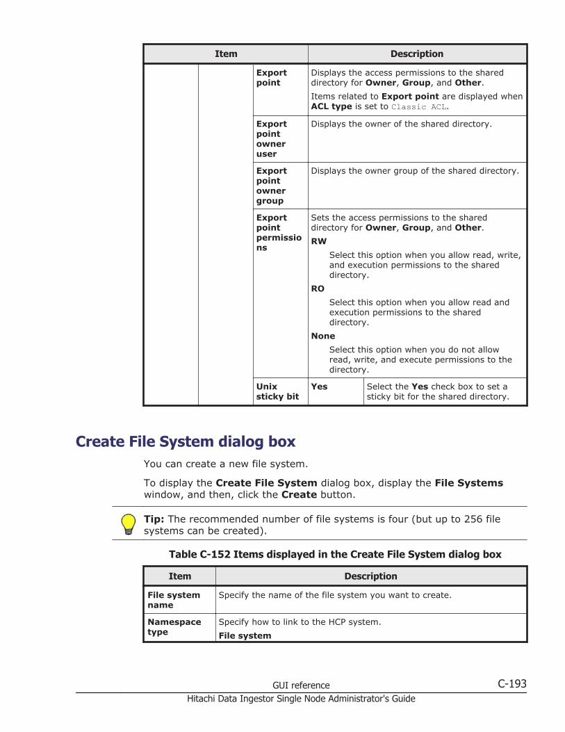
Item Description
Exportpoint
Displays the access permissions to the shareddirectory for Owner, Group, and Other.
Items related to Export point are displayed whenACL type is set to Classic ACL.
Exportpointowneruser
Displays the owner of the shared directory.
Exportpointownergroup
Displays the owner group of the shared directory.
Exportpointpermissions
Sets the access permissions to the shareddirectory for Owner, Group, and Other.
RW
Select this option when you allow read, write,and execution permissions to the shareddirectory.
RO
Select this option when you allow read andexecution permissions to the shareddirectory.
None
Select this option when you do not allowread, write, and execute permissions to thedirectory.
Unixsticky bit
Yes Select the Yes check box to set asticky bit for the shared directory.
Create File System dialog boxYou can create a new file system.
To display the Create File System dialog box, display the File Systemswindow, and then, click the Create button.
Tip: The recommended number of file systems is four (but up to 256 filesystems can be created).
Table C-152 Items displayed in the Create File System dialog box
Item Description
File systemname
Specify the name of the file system you want to create.
Namespacetype
Specify how to link to the HCP system.
File system
GUI reference C-193Hitachi Data Ingestor Single Node Administrator's Guide
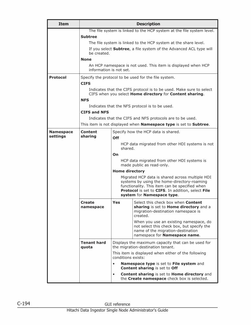
Item Description
The file system is linked to the HCP system at the file system level.
Subtree
The file system is linked to the HCP system at the share level.
If you select Subtree, a file system of the Advanced ACL type willbe created.
None
An HCP namespace is not used. This item is displayed when HCPinformation is not set.
Protocol Specify the protocol to be used for the file system.
CIFS
Indicates that the CIFS protocol is to be used. Make sure to selectCIFS when you select Home directory for Content sharing.
NFS
Indicates that the NFS protocol is to be used.
CIFS and NFS
Indicates that the CIFS and NFS protocols are to be used.
This item is not displayed when Namespace type is set to Subtree.
Namespacesettings
Contentsharing
Specify how the HCP data is shared.
Off
HCP data migrated from other HDI systems is notshared.
On
HCP data migrated from other HDI systems ismade public as read-only.
Home directory
Migrated HCP data is shared across multiple HDIsystems by using the home-directory-roamingfunctionality. This item can be specified whenProtocol is set to CIFS. In addition, select Filesystem for Namespace type.
Createnamespace
Yes Select this check box when Contentsharing is set to Home directory and amigration-destination namespace iscreated.
When you use an existing namespace, donot select this check box, but specify thename of the migration-destinationnamespace for Namespace name.
Tenant hardquota
Displays the maximum capacity that can be used forthe migration-destination tenant.
This item is displayed when either of the followingconditions exists:
• Namespace type is set to File system andContent sharing is set to Off
• Content sharing is set to Home directory andthe Create namespace check box is selected.
C-194 GUI referenceHitachi Data Ingestor Single Node Administrator's Guide

Item Description
Storagecapacity used
Displays the current capacity usage of the migration-destination tenant.
This item is displayed when either of the followingconditions exists:
• Namespace type is set to File system andContent sharing is set to Off
• Content sharing is set to Home directory andthe Create namespace check box is selected.
Quota Specify the quota to be assigned to the migration-destination namespace. Specify the quota to beassigned to the namespace in GB or TB units. Specifya value that is smaller than the value for Tenant hardquota.
This item is displayed when either of the followingconditions exists:
• Namespace type is set to File system andContent sharing is set to Off
• Content sharing is set to Home directory andthe Create namespace check box is selected.
NamespaceFQDN
Specify the name of the HCP namespace in fullyqualified domain name (FQDN) format.
This item is displayed when Namespace type is set toFile system and Content sharing is set to On.
External HCPhost name
If the HCP system to be linked uses a relaying device,such as a load balancer, when connecting to thenetwork, specify the host name or IP address that hasbeen made external and is used to connect to the HCPsystem.
This item is displayed when Namespace type is set toFile system and Content sharing is set to On.
Namespace-accessaccount
User Specify the user name of the account usedto view the HCP namespace.
Items related to Namespace-accessaccount are displayed when Namespacetype is set to File system and Contentsharing is set to On.
Password
Specify the password of the account usedto view the namespace.
After specifying the user name andpassword, click the Test Connectionbutton to check whether connection to HCPis possible.
Namespacename
When Content sharing is set to Home directory, ifyou want to use an existing namespace, specify thename of the migration-destination namespace.
After you specify a namespace name, click the TestConnection button to check whether the namespaceis accessible.
GUI reference C-195Hitachi Data Ingestor Single Node Administrator's Guide

Item Description
Migrationschedule
Start date Specify the first date on which migration is to beexecuted. Click the calendar icon, and then click a datein the displayed calendar.
You can specify items related to Migration schedulewhen Content sharing is set to Off.
Regular taskscheduling
Interval Specify the migration interval. Move theslider on the bar that indicates the intervalto specify an interval in the range from 15minutes to 1 week.
The currently set interval is displayed onthe bar in the following format:
Every numerical-value <minute(s),hour(s), day(s), or week>
Starttime
Specify the start time of the migration.
Maximumduration
Specify how long migration processing cancontinue.
Cachesettings
Storagesystem
Select the storage destination (internal hard disk orstorage system) for the data in the file system whenmultiple volume groups exist. Storage systems thatcan be selected are displayed in a drop-down list in thefollowing format:
storage-system-model-name | serial-number
For internal hard disks, INTERNAL is displayed for themodel name.
Volume group Select a volume group to be used by the file systemwhen multiple volume groups exist. Volume groupsthat can be selected are displayed in a drop-down listin the following format:
volume-group-name | total-capacity-of-volume-group(maximum-capacity-that-can-be-allocated-to-file-system Available) drive-type
Unallocatedcapacity
Displays the capacity that can be allocated to the filesystem when one volume group exists.
Capacity Specify the capacity to be allocated to the file systemin GB or TB units.
The upper limit for expansion of the file systemcapacity is also displayed on the right-hand side. If theinitial capacity of a created file system is equal to orless than 32 GB, the maximum capacity afterexpansion will be less than the displayed value. Fordetails about the initial capacity of a created filesystem and the maximum capacity after expansion,see the CLI Administrator's Guide.
Namespacesharingsettings
Namespace-accessaccount
Create Select this to create an account for viewingthe migration-destination namespace forother HDI systems on which the migratedHCP data is shared only for viewing.
C-196 GUI referenceHitachi Data Ingestor Single Node Administrator's Guide
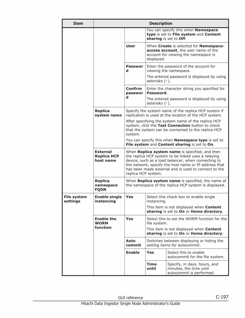
Item Description
You can specify this when Namespacetype is set to File system and Contentsharing is set to Off.
User When Create is selected for Namespace-access account, the user name of theaccount for viewing the namespace isdisplayed.
Password
Enter the password of the account forviewing the namespace.
The entered password is displayed by usingasterisks (*).
Confirmpassword
Enter the character string you specified forPassword.
The entered password is displayed by usingasterisks (*).
Replicasystem name
Specify the system name of the replica HCP system ifreplication is used at the location of the HCP system.
After specifying the system name of the replica HCPsystem, click the Test Connection button to checkthat the system can be connected to the replica HCPsystem.
You can specify this when Namespace type is set toFile system and Content sharing is set to On.
ExternalReplica HCPhost name
When Replica system name is specified, and thenthe replica HCP system to be linked uses a relayingdevice, such as a load balancer, when connecting tothe network, specify the host name or IP address thathas been made external and is used to connect to thereplica HCP system.
ReplicanamespaceFQDN
When Replica system name is specified, the name ofthe namespace of the replica HCP system is displayed.
File systemsettings
Enable singleinstancing
Yes Select this check box to enable singleinstancing.
This item is not displayed when Contentsharing is set to On or Home directory.
Enable theWORMfunction
Yes Select this to set the WORM function for thefile system.
This item is not displayed when Contentsharing is set to On or Home directory.
Autocommit
Switches between displaying or hiding thesetting items for autocommit.
Enable Yes Select this to enableautocommit for the file system.
Timeuntil
Specify, in days, hours, andminutes, the time untilautocommit is performed.
GUI reference C-197Hitachi Data Ingestor Single Node Administrator's Guide

Item Description
committed
day(s)
Specify a value in the rangefrom 0 to 10950.
hour(s)
Specify a value in the rangefrom 0 to 23.
minute(s)
Specify a value in the rangefrom 0 to 59.
Defaultretention period
Select Infinite to set anunlimited default retentionperiod.
In the following items, specifythe default retention period indays, hours, and minutes:
day(s)
Specify a value in the rangefrom 0 to 10950.
hour(s)
Specify a value in the rangefrom 0 to 23.
minute(s)
Specify a value in the rangefrom 0 to 59.
Enablerenameof emptydirectories
Yes Select this to allow renaming ofempty directories in a WORMfile system.
Use fileversionrestore
Yes Select this to make the past version files(past version directories) migrated to theHCP system available to clients.
You can specify this when Contentsharing is set to Off or Home directory.
Customschedule#
Enable To enable the custom schedule,select this.
If you set multiple schedules,processing is executed in order,starting with the schedule thatuses the shortest time unit. Fordetails about the results ofexecuting processing accordingto the custom schedule settings,see the Installation andConfiguration Guide.
• Keep 15-MINUTEversions for: The oldestpast version directory with15-minute time units (hour
C-198 GUI referenceHitachi Data Ingestor Single Node Administrator's Guide
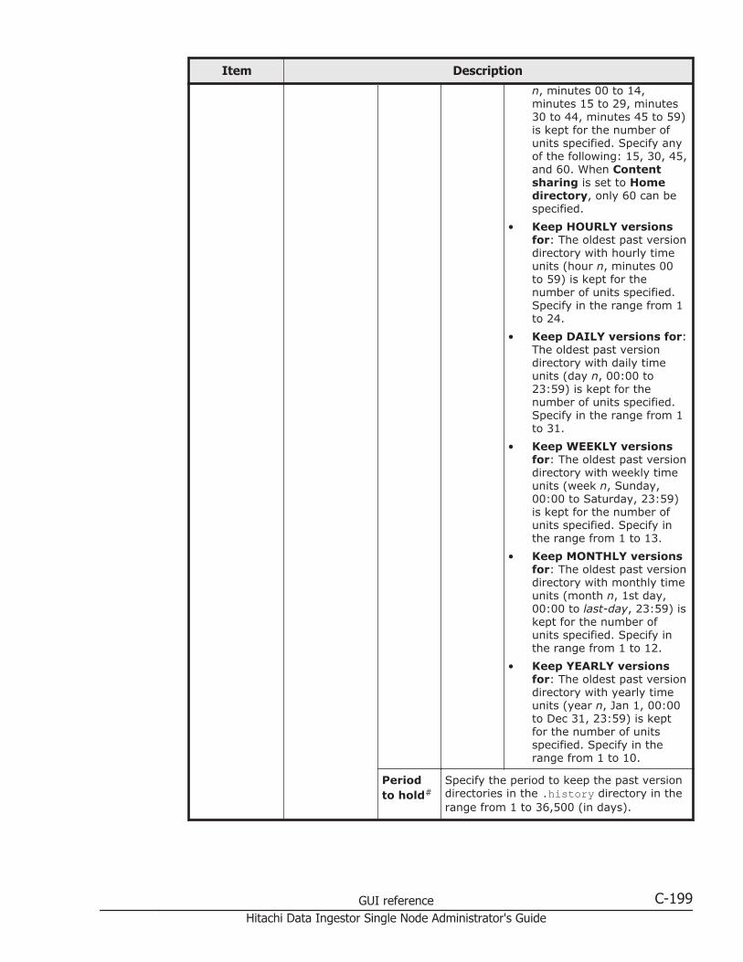
Item Description
n, minutes 00 to 14,minutes 15 to 29, minutes30 to 44, minutes 45 to 59)is kept for the number ofunits specified. Specify anyof the following: 15, 30, 45,and 60. When Contentsharing is set to Homedirectory, only 60 can bespecified.
• Keep HOURLY versionsfor: The oldest past versiondirectory with hourly timeunits (hour n, minutes 00to 59) is kept for thenumber of units specified.Specify in the range from 1to 24.
• Keep DAILY versions for:The oldest past versiondirectory with daily timeunits (day n, 00:00 to23:59) is kept for thenumber of units specified.Specify in the range from 1to 31.
• Keep WEEKLY versionsfor: The oldest past versiondirectory with weekly timeunits (week n, Sunday,00:00 to Saturday, 23:59)is kept for the number ofunits specified. Specify inthe range from 1 to 13.
• Keep MONTHLY versionsfor: The oldest past versiondirectory with monthly timeunits (month n, 1st day,00:00 to last-day, 23:59) iskept for the number ofunits specified. Specify inthe range from 1 to 12.
• Keep YEARLY versionsfor: The oldest past versiondirectory with yearly timeunits (year n, Jan 1, 00:00to Dec 31, 23:59) is keptfor the number of unitsspecified. Specify in therange from 1 to 10.
Periodto hold#
Specify the period to keep the past versiondirectories in the .history directory in therange from 1 to 36,500 (in days).
GUI reference C-199Hitachi Data Ingestor Single Node Administrator's Guide
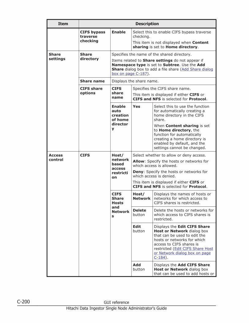
Item Description
CIFS bypasstraversechecking
Enable Select this to enable CIFS bypass traversechecking.
This item is not displayed when Contentsharing is set to Home directory.
Sharesettings
Sharedirectory
Specifies the name of the shared directory.
Items related to Share settings do not appear ifNamespace type is set to Subtree. Use the AddShare dialog box to add a file share (Add Share dialogbox on page C-187).
Share name Displays the share name.
CIFS shareoptions
CIFSsharename
Specifies the CIFS share name.
This item is displayed if either CIFS orCIFS and NFS is selected for Protocol.
Enableautocreationof homedirectory
Yes Select this to use the functionfor automatically creating ahome directory in the CIFSshare.
When Content sharing is setto Home directory, thefunction for automaticallycreating a home directory isenabled by default, and thesettings cannot be changed.
Accesscontrol
CIFS Host/networkbasedaccessrestriction
Select whether to allow or deny access.
Allow: Specify the hosts or networks forwhich access is allowed.
Deny: Specify the hosts or networks forwhich access is denied.
This item is displayed if either CIFS orCIFS and NFS is selected for Protocol.
CIFSShareHostsandNetworks
Host/Network
Displays the names of hosts ornetworks for which access toCIFS shares is restricted.
Deletebutton
Delete the hosts or networks forwhich access to CIFS shares isrestricted.
Editbutton
Displays the Edit CIFS ShareHost or Network dialog boxthat can be used to edit thehosts or networks for whichaccess to CIFS shares isrestricted (Edit CIFS Share Hostor Network dialog box on pageC-184).
Addbutton
Displays the Add CIFS ShareHost or Network dialog boxthat can be used to add hosts or
C-200 GUI referenceHitachi Data Ingestor Single Node Administrator's Guide
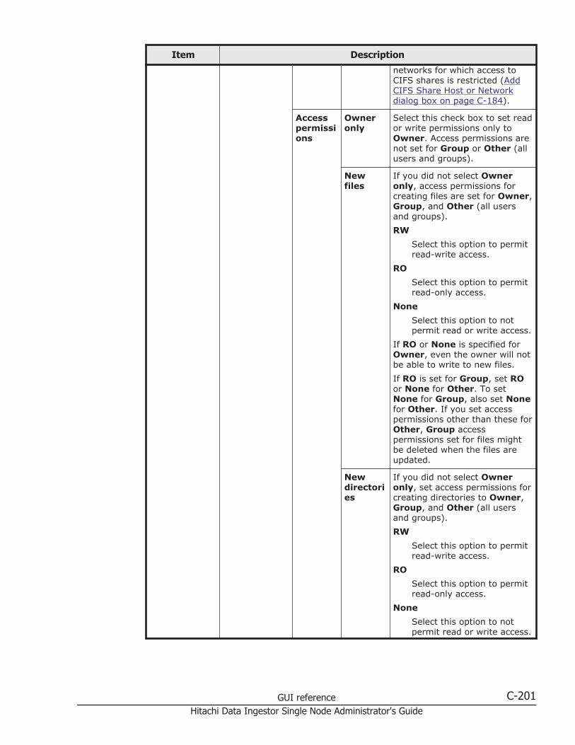
Item Description
networks for which access toCIFS shares is restricted (AddCIFS Share Host or Networkdialog box on page C-184).
Accesspermissions
Owneronly
Select this check box to set reador write permissions only toOwner. Access permissions arenot set for Group or Other (allusers and groups).
Newfiles
If you did not select Owneronly, access permissions forcreating files are set for Owner,Group, and Other (all usersand groups).
RW
Select this option to permitread-write access.
RO
Select this option to permitread-only access.
None
Select this option to notpermit read or write access.
If RO or None is specified forOwner, even the owner will notbe able to write to new files.
If RO is set for Group, set ROor None for Other. To setNone for Group, also set Nonefor Other. If you set accesspermissions other than these forOther, Group accesspermissions set for files mightbe deleted when the files areupdated.
Newdirectories
If you did not select Owneronly, set access permissions forcreating directories to Owner,Group, and Other (all usersand groups).
RW
Select this option to permitread-write access.
RO
Select this option to permitread-only access.
None
Select this option to notpermit read or write access.
GUI reference C-201Hitachi Data Ingestor Single Node Administrator's Guide
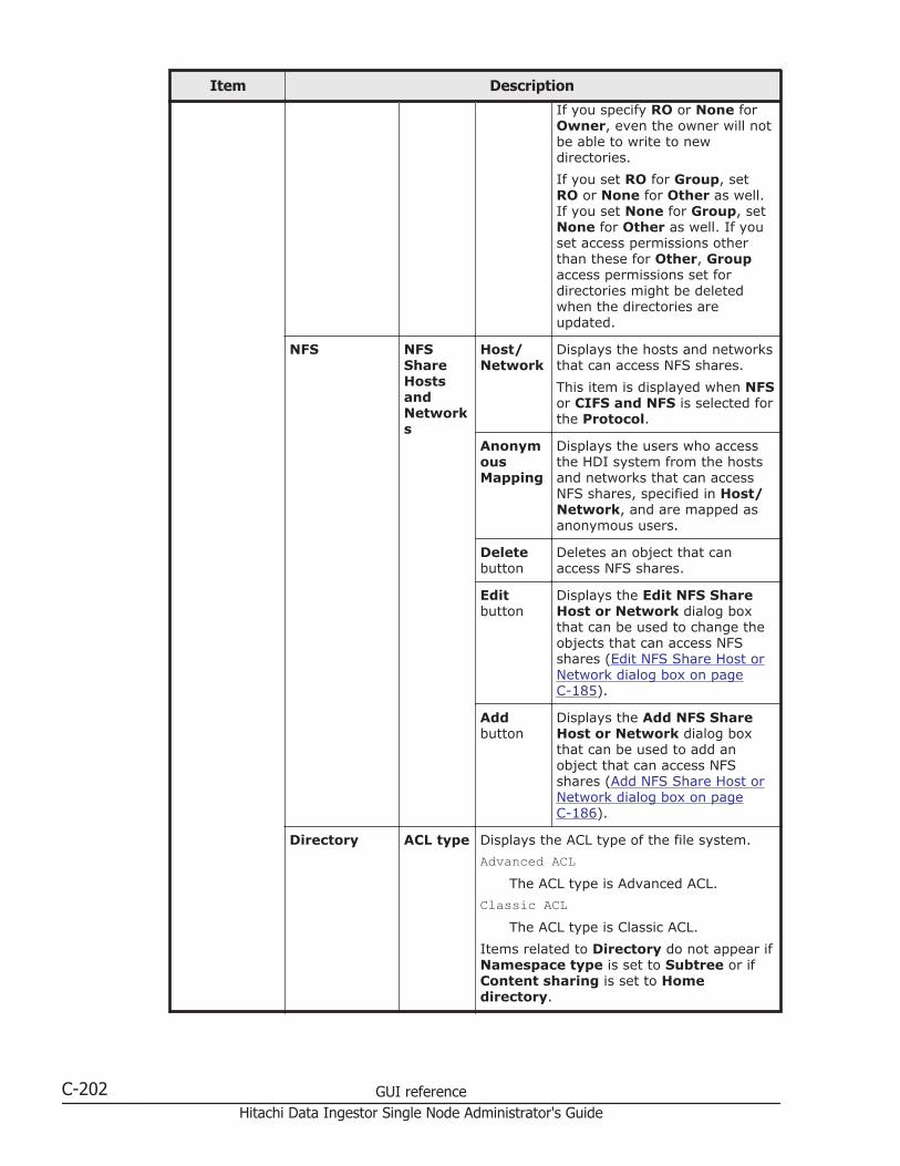
Item Description
If you specify RO or None forOwner, even the owner will notbe able to write to newdirectories.
If you set RO for Group, setRO or None for Other as well.If you set None for Group, setNone for Other as well. If youset access permissions otherthan these for Other, Groupaccess permissions set fordirectories might be deletedwhen the directories areupdated.
NFS NFSShareHostsandNetworks
Host/Network
Displays the hosts and networksthat can access NFS shares.
This item is displayed when NFSor CIFS and NFS is selected forthe Protocol.
AnonymousMapping
Displays the users who accessthe HDI system from the hostsand networks that can accessNFS shares, specified in Host/Network, and are mapped asanonymous users.
Deletebutton
Deletes an object that canaccess NFS shares.
Editbutton
Displays the Edit NFS ShareHost or Network dialog boxthat can be used to change theobjects that can access NFSshares (Edit NFS Share Host orNetwork dialog box on pageC-185).
Addbutton
Displays the Add NFS ShareHost or Network dialog boxthat can be used to add anobject that can access NFSshares (Add NFS Share Host orNetwork dialog box on pageC-186).
Directory ACL type Displays the ACL type of the file system.
Advanced ACLThe ACL type is Advanced ACL.
Classic ACLThe ACL type is Classic ACL.
Items related to Directory do not appear ifNamespace type is set to Subtree or ifContent sharing is set to Homedirectory.
C-202 GUI referenceHitachi Data Ingestor Single Node Administrator's Guide

Item Description
ACLRegistered UsersandGroups
Type Displays the types of targetusers and groups.
This item is displayed whenCIFS or CIFS and NFS isselected for the Protocol.
Name Displays the names of targetusers or groups.
AccountType
Displays whether the accounthas been registered as a user orgroup.
Permissions
Displays the operations forwhich access is allowed ordenied.
Apply to Displays whether the ACLsettings are also applied to thesubfolders and files as well asthis folder (shared directory).
Settingbutton
Displays the Advanced ACLSettings dialog box that can beused to set ACLs to the shareddirectory (Advanced ACLSettings dialog box on pageC-211).
Exportpoint
Displays the access permissions to theshared directory for Owner, Group, andOther.
This item is displayed when NFS is selectedfor Protocol.
Exportpointowneruser
Displays the owner of the shared directory.
Exportpointownergroup
Displays the owner group of the shareddirectory.
Exportpointpermissions
Sets the access permissions to the shareddirectory for Owner, Group, and Other.
RW
Select this option when you allow read,write, and execution permissions to theshared directory.
RO
Select this option when you allow readand execution permissions to theshared directory.
None
GUI reference C-203Hitachi Data Ingestor Single Node Administrator's Guide
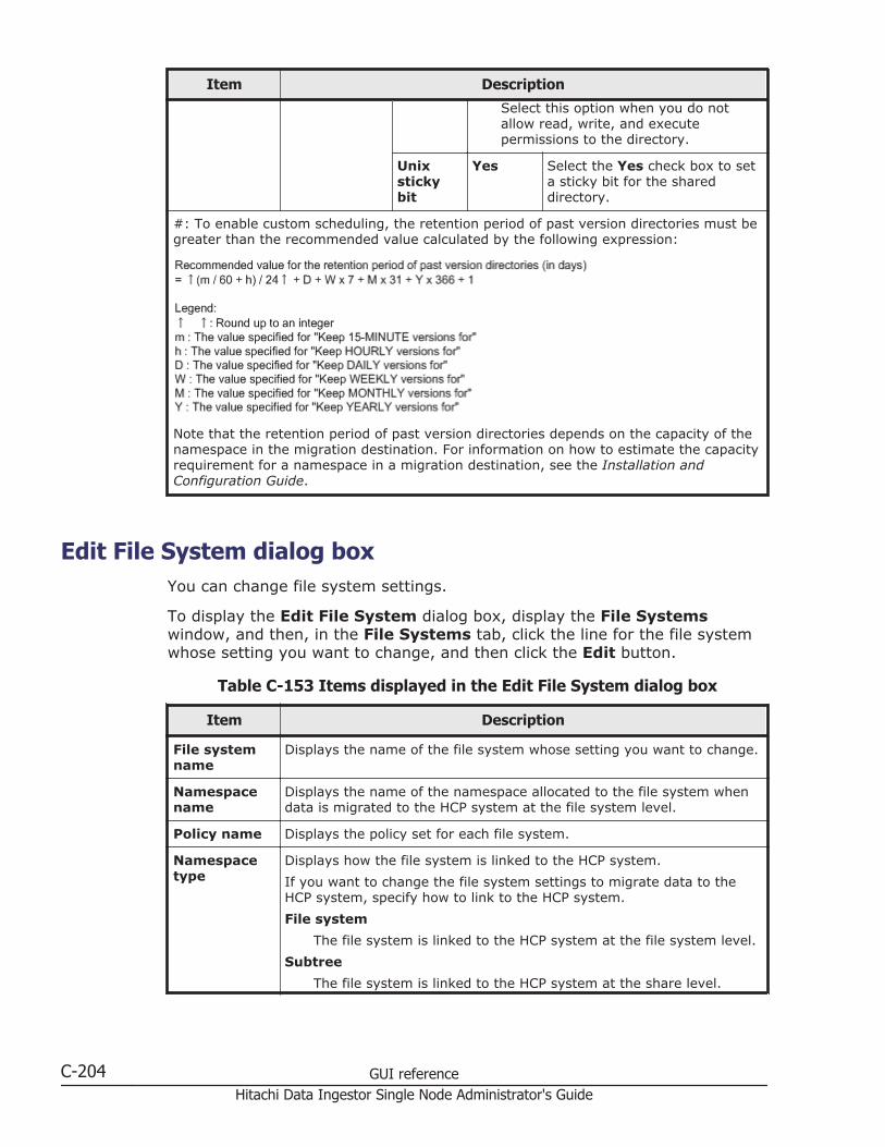
Item Description
Select this option when you do notallow read, write, and executepermissions to the directory.
Unixstickybit
Yes Select the Yes check box to seta sticky bit for the shareddirectory.
#: To enable custom scheduling, the retention period of past version directories must begreater than the recommended value calculated by the following expression:
Note that the retention period of past version directories depends on the capacity of thenamespace in the migration destination. For information on how to estimate the capacityrequirement for a namespace in a migration destination, see the Installation andConfiguration Guide.
Edit File System dialog boxYou can change file system settings.
To display the Edit File System dialog box, display the File Systemswindow, and then, in the File Systems tab, click the line for the file systemwhose setting you want to change, and then click the Edit button.
Table C-153 Items displayed in the Edit File System dialog box
Item Description
File systemname
Displays the name of the file system whose setting you want to change.
Namespacename
Displays the name of the namespace allocated to the file system whendata is migrated to the HCP system at the file system level.
Policy name Displays the policy set for each file system.
Namespacetype
Displays how the file system is linked to the HCP system.
If you want to change the file system settings to migrate data to theHCP system, specify how to link to the HCP system.
File system
The file system is linked to the HCP system at the file system level.
Subtree
The file system is linked to the HCP system at the share level.
C-204 GUI referenceHitachi Data Ingestor Single Node Administrator's Guide
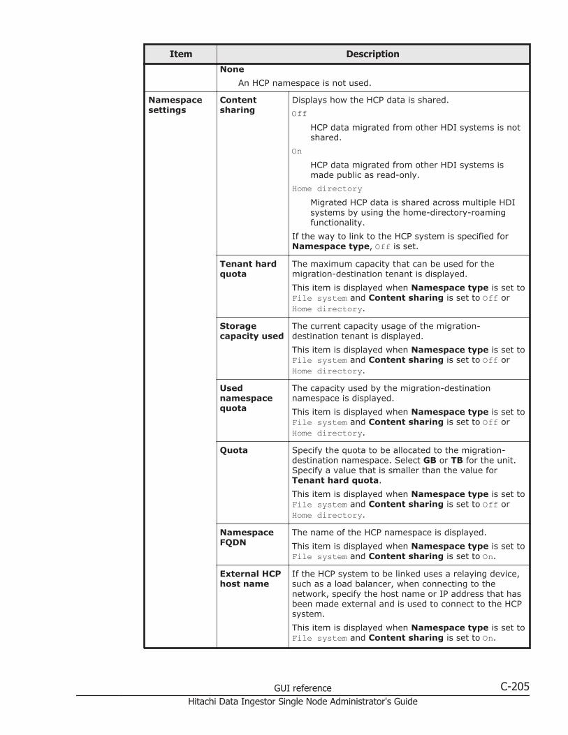
Item Description
None
An HCP namespace is not used.
Namespacesettings
Contentsharing
Displays how the HCP data is shared.
OffHCP data migrated from other HDI systems is notshared.
OnHCP data migrated from other HDI systems ismade public as read-only.
Home directoryMigrated HCP data is shared across multiple HDIsystems by using the home-directory-roamingfunctionality.
If the way to link to the HCP system is specified forNamespace type, Off is set.
Tenant hardquota
The maximum capacity that can be used for themigration-destination tenant is displayed.
This item is displayed when Namespace type is set toFile system and Content sharing is set to Off orHome directory.
Storagecapacity used
The current capacity usage of the migration-destination tenant is displayed.
This item is displayed when Namespace type is set toFile system and Content sharing is set to Off orHome directory.
Usednamespacequota
The capacity used by the migration-destinationnamespace is displayed.
This item is displayed when Namespace type is set toFile system and Content sharing is set to Off orHome directory.
Quota Specify the quota to be allocated to the migration-destination namespace. Select GB or TB for the unit.Specify a value that is smaller than the value forTenant hard quota.
This item is displayed when Namespace type is set toFile system and Content sharing is set to Off orHome directory.
NamespaceFQDN
The name of the HCP namespace is displayed.
This item is displayed when Namespace type is set toFile system and Content sharing is set to On.
External HCPhost name
If the HCP system to be linked uses a relaying device,such as a load balancer, when connecting to thenetwork, specify the host name or IP address that hasbeen made external and is used to connect to the HCPsystem.
This item is displayed when Namespace type is set toFile system and Content sharing is set to On.
GUI reference C-205Hitachi Data Ingestor Single Node Administrator's Guide

Item Description
Namespace-accessaccount
User Specify the user name of the account forviewing the namespace.
Items related to Namespace-accessaccount are displayed when Namespacetype is set to File system and Contentsharing is set to On.
Password
Specify the password of the account forviewing the HCP namespace.
After specifying the user name andpassword, click the Test Connectionbutton to check whether connection to HCPis possible.
This item is displayed when Namespacetype is set to File system and Contentsharing is set to On.
Migrationschedule
Start date Specify the first date on which migration is to beexecuted. Click the calendar icon, and then click a datein the displayed calendar.
You can specify items related to Migration schedulewhen Content sharing is set to Off.
Regular taskscheduling
Interval Specify the migration interval. Move theslider on the bar that indicates the intervalto specify an interval in the range from 15minutes to 1 week.
The currently set interval is displayed onthe bar in the following format:
Every numerical-value <minute(s), hour(s),day(s), or week>
Starttime
Specify the start time of the migration.
Maximumduration
Specify how long migration processing isallowed to continue.
Cachesettings
Storagesystem
Displays the storage destination for the data in the filesystem when multiple volume groups exist.
Volume group Displays the volume group being used by the filesystem when multiple volume groups exist.
Unallocatedcapacity
Displays the capacity that can be allocated to the filesystem when one volume group exists.
Capacity Specify the capacity to be allocated to the file systemin GB or TB units.
The upper limit for expansion of the file systemcapacity is also displayed on the right-hand side. If theinitial capacity of a created file system is equal to orless than 32 GB, the maximum capacity afterexpansion will be less than the displayed value. Fordetails about the initial capacity of a created file
C-206 GUI referenceHitachi Data Ingestor Single Node Administrator's Guide
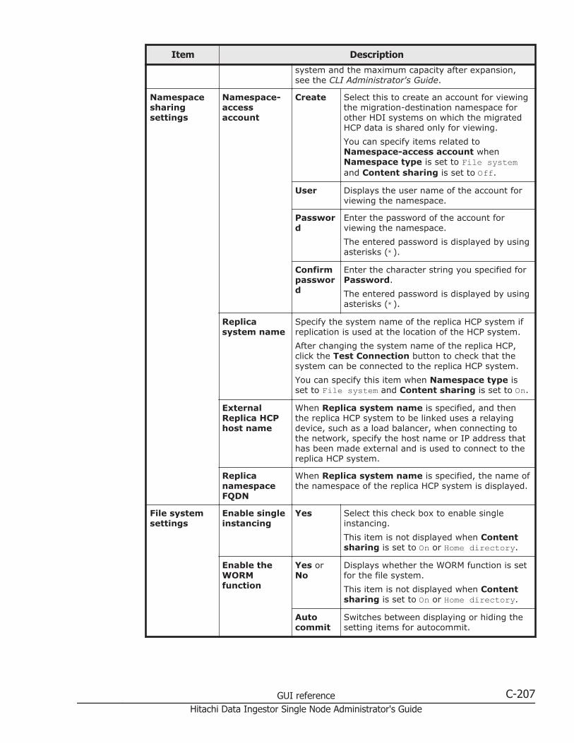
Item Description
system and the maximum capacity after expansion,see the CLI Administrator's Guide.
Namespacesharingsettings
Namespace-accessaccount
Create Select this to create an account for viewingthe migration-destination namespace forother HDI systems on which the migratedHCP data is shared only for viewing.
You can specify items related toNamespace-access account whenNamespace type is set to File systemand Content sharing is set to Off.
User Displays the user name of the account forviewing the namespace.
Password
Enter the password of the account forviewing the namespace.
The entered password is displayed by usingasterisks (*).
Confirmpassword
Enter the character string you specified forPassword.
The entered password is displayed by usingasterisks (*).
Replicasystem name
Specify the system name of the replica HCP system ifreplication is used at the location of the HCP system.
After changing the system name of the replica HCP,click the Test Connection button to check that thesystem can be connected to the replica HCP system.
You can specify this item when Namespace type isset to File system and Content sharing is set to On.
ExternalReplica HCPhost name
When Replica system name is specified, and thenthe replica HCP system to be linked uses a relayingdevice, such as a load balancer, when connecting tothe network, specify the host name or IP address thathas been made external and is used to connect to thereplica HCP system.
ReplicanamespaceFQDN
When Replica system name is specified, the name ofthe namespace of the replica HCP system is displayed.
File systemsettings
Enable singleinstancing
Yes Select this check box to enable singleinstancing.
This item is not displayed when Contentsharing is set to On or Home directory.
Enable theWORMfunction
Yes orNo
Displays whether the WORM function is setfor the file system.
This item is not displayed when Contentsharing is set to On or Home directory.
Autocommit
Switches between displaying or hiding thesetting items for autocommit.
GUI reference C-207Hitachi Data Ingestor Single Node Administrator's Guide
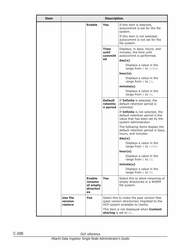
Item Description
Enable Yes If this item is selected,autocommit is set for the filesystem.
If this item is not selected,autocommit is not set for thefile system.
Timeuntilcommitted
Displays, in days, hours, andminutes, the time untilautocommit is performed.
day(s)
Displays a value in therange from 0 to 10950.
hour(s)
Displays a value in therange from 0 to 23.
minute(s)
Displays a value in therange from 0 to 59.
Defaultretention period
If Infinite is selected, thedefault retention period isunlimited.
If Infinite is not selected, thedefault retention period is thevalue that has been set by thesystem administrator.
The following items display thedefault retention period in days,hours, and minutes:
day(s)
Displays a value in therange from 0 to 10950.
hour(s)
Displays a value in therange from 0 to 23.
minute(s)
Displays a value in therange from 0 to 59.
Enablerenameof emptydirectories
Yes Select this to allow renaming ofempty directories in a WORMfile system.
Use fileversionrestore
Yes Select this to make the past version files(past version directories) migrated to theHCP system available to clients.
This item is not displayed when Contentsharing is set to On.
C-208 GUI referenceHitachi Data Ingestor Single Node Administrator's Guide

Item Description
Customschedule#
Enable To enable the custom schedule,select this.
If you set multiple schedules,processing is executed in order,starting with the schedule thatuses the shortest time unit. Fordetails about the results ofexecuting processing accordingto the custom schedule settings,see the Installation andConfiguration Guide.
• Keep 15-MINUTEversions for: The oldestpast version directory with15-minute time units (hourn, minutes 00 to 14,minutes 15 to 29, minutes30 to 44, minutes 45 to 59)is kept for the number ofunits specified. Specify anyof the following: 15, 30, 45,and 60.
• Keep HOURLY versionsfor: The oldest past versiondirectory with hourly timeunits (hour n, minutes 00to 59) is kept for thenumber of units specified.Specify in the range from 1to 24.
• Keep DAILY versions for:The oldest past versiondirectory with daily timeunits (day n, 00:00 to23:59) is kept for thenumber of units specified.Specify in the range from 1to 31.
• Keep WEEKLY versionsfor: The oldest past versiondirectory with weekly timeunits (week n, Sunday,00:00 to Saturday, 23:59)is kept for the number ofunits specified. Specify inthe range from 1 to 13.
• Keep MONTHLY versionsfor: The oldest past versiondirectory with monthly timeunits (month n, 1st day,00:00 to last-day, 23:59) iskept for the number ofunits specified. Specify inthe range from 1 to 12.
GUI reference C-209Hitachi Data Ingestor Single Node Administrator's Guide
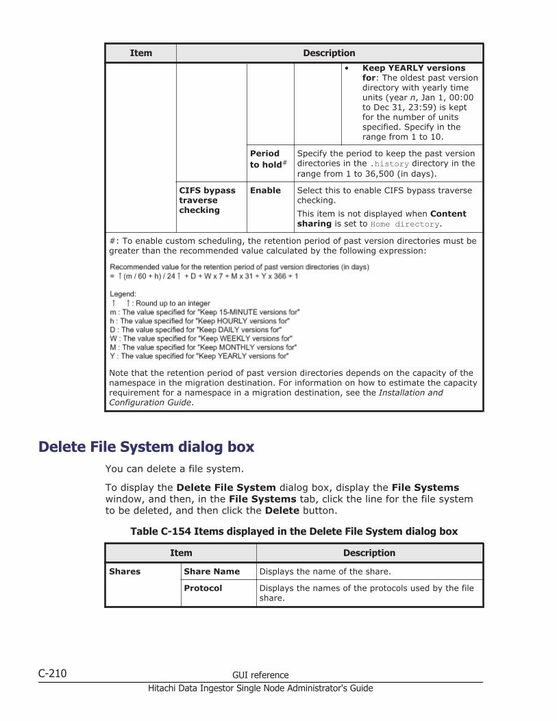
Item Description
• Keep YEARLY versionsfor: The oldest past versiondirectory with yearly timeunits (year n, Jan 1, 00:00to Dec 31, 23:59) is keptfor the number of unitsspecified. Specify in therange from 1 to 10.
Periodto hold#
Specify the period to keep the past versiondirectories in the .history directory in therange from 1 to 36,500 (in days).
CIFS bypasstraversechecking
Enable Select this to enable CIFS bypass traversechecking.
This item is not displayed when Contentsharing is set to Home directory.
#: To enable custom scheduling, the retention period of past version directories must begreater than the recommended value calculated by the following expression:
Note that the retention period of past version directories depends on the capacity of thenamespace in the migration destination. For information on how to estimate the capacityrequirement for a namespace in a migration destination, see the Installation andConfiguration Guide.
Delete File System dialog boxYou can delete a file system.
To display the Delete File System dialog box, display the File Systemswindow, and then, in the File Systems tab, click the line for the file systemto be deleted, and then click the Delete button.
Table C-154 Items displayed in the Delete File System dialog box
Item Description
Shares Share Name Displays the name of the share.
Protocol Displays the names of the protocols used by the fileshare.
C-210 GUI referenceHitachi Data Ingestor Single Node Administrator's Guide

Item Description
Yes, I have read the abovewarning and wish to delete thespecified file system. check box
Select this check box if you want to delete the filesystem.
Apply button Delete the file system. The Yes, I have read theabove warning and wish to delete the specifiedfile system. check box must be selected before youclick this button.
Advanced ACL Settings dialog boxIn the Advanced ACL Settings dialog box, you can set ACLs for the shareddirectory.
To display the Advanced ACL Settings dialog box, in the Create FileSystem dialog box, click the Setting button in ACL Registered Users andGroups.
Table C-155 Items displayed in the Advanced ACL Settings dialog box
Item Description
ACL registeredusers andgroups
User or groupname
Specify the name of the target user or group. This isnot case sensitive in Windows.
You can also specify the following built-in accountsin a Windows domain:
• EveryoneSpecify this as a group (by clicking the GroupAdd > button).
• CREATOR GROUPSpecify this as a group (by clicking the GroupAdd > button).
• CREATOR OWNERSpecify this as a user (by clicking the User Add> button).
Permissions Select in the check box whether to allow or denyaccess. Only operations corresponding to the itemsfor which Allow is selected are allowed.
• Full control
• Modify
• Read and execute
• Read
• Write
• List folder contents
Apply theseACLs to thisfolder, sub-
Select this check box to apply the ACL settings tothe subfolders and files as well as the selected folder(shared directory). If this check box is not selected,
GUI reference C-211Hitachi Data Ingestor Single Node Administrator's Guide
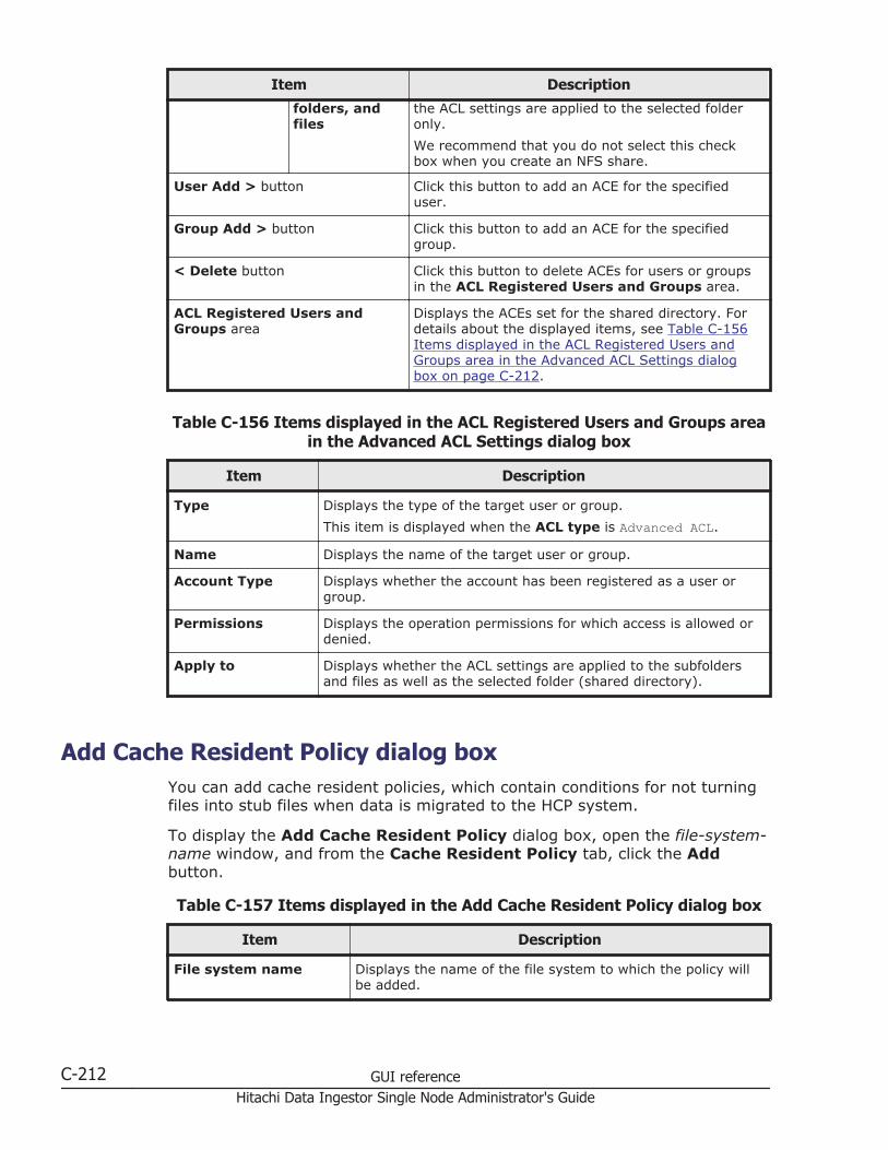
Item Description
folders, andfiles
the ACL settings are applied to the selected folderonly.
We recommend that you do not select this checkbox when you create an NFS share.
User Add > button Click this button to add an ACE for the specifieduser.
Group Add > button Click this button to add an ACE for the specifiedgroup.
< Delete button Click this button to delete ACEs for users or groupsin the ACL Registered Users and Groups area.
ACL Registered Users andGroups area
Displays the ACEs set for the shared directory. Fordetails about the displayed items, see Table C-156Items displayed in the ACL Registered Users andGroups area in the Advanced ACL Settings dialogbox on page C-212.
Table C-156 Items displayed in the ACL Registered Users and Groups areain the Advanced ACL Settings dialog box
Item Description
Type Displays the type of the target user or group.
This item is displayed when the ACL type is Advanced ACL.
Name Displays the name of the target user or group.
Account Type Displays whether the account has been registered as a user orgroup.
Permissions Displays the operation permissions for which access is allowed ordenied.
Apply to Displays whether the ACL settings are applied to the subfoldersand files as well as the selected folder (shared directory).
Add Cache Resident Policy dialog boxYou can add cache resident policies, which contain conditions for not turningfiles into stub files when data is migrated to the HCP system.
To display the Add Cache Resident Policy dialog box, open the file-system-name window, and from the Cache Resident Policy tab, click the Addbutton.
Table C-157 Items displayed in the Add Cache Resident Policy dialog box
Item Description
File system name Displays the name of the file system to which the policy willbe added.
C-212 GUI referenceHitachi Data Ingestor Single Node Administrator's Guide
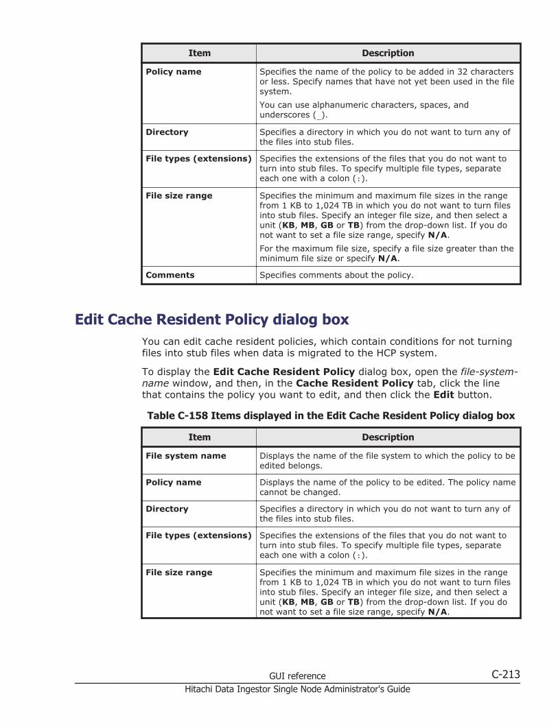
Item Description
Policy name Specifies the name of the policy to be added in 32 charactersor less. Specify names that have not yet been used in the filesystem.
You can use alphanumeric characters, spaces, andunderscores (_).
Directory Specifies a directory in which you do not want to turn any ofthe files into stub files.
File types (extensions) Specifies the extensions of the files that you do not want toturn into stub files. To specify multiple file types, separateeach one with a colon (:).
File size range Specifies the minimum and maximum file sizes in the rangefrom 1 KB to 1,024 TB in which you do not want to turn filesinto stub files. Specify an integer file size, and then select aunit (KB, MB, GB or TB) from the drop-down list. If you donot want to set a file size range, specify N/A.
For the maximum file size, specify a file size greater than theminimum file size or specify N/A.
Comments Specifies comments about the policy.
Edit Cache Resident Policy dialog boxYou can edit cache resident policies, which contain conditions for not turningfiles into stub files when data is migrated to the HCP system.
To display the Edit Cache Resident Policy dialog box, open the file-system-name window, and then, in the Cache Resident Policy tab, click the linethat contains the policy you want to edit, and then click the Edit button.
Table C-158 Items displayed in the Edit Cache Resident Policy dialog box
Item Description
File system name Displays the name of the file system to which the policy to beedited belongs.
Policy name Displays the name of the policy to be edited. The policy namecannot be changed.
Directory Specifies a directory in which you do not want to turn any ofthe files into stub files.
File types (extensions) Specifies the extensions of the files that you do not want toturn into stub files. To specify multiple file types, separateeach one with a colon (:).
File size range Specifies the minimum and maximum file sizes in the rangefrom 1 KB to 1,024 TB in which you do not want to turn filesinto stub files. Specify an integer file size, and then select aunit (KB, MB, GB or TB) from the drop-down list. If you donot want to set a file size range, specify N/A.
GUI reference C-213Hitachi Data Ingestor Single Node Administrator's Guide
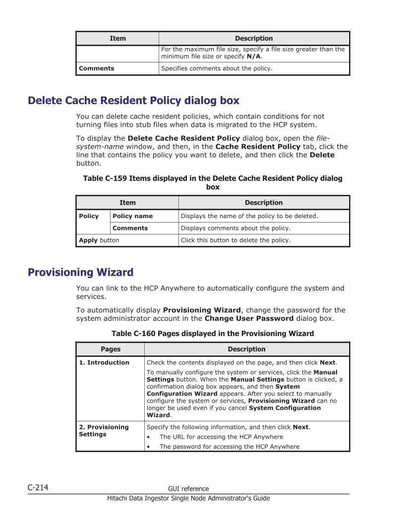
Item Description
For the maximum file size, specify a file size greater than theminimum file size or specify N/A.
Comments Specifies comments about the policy.
Delete Cache Resident Policy dialog boxYou can delete cache resident policies, which contain conditions for notturning files into stub files when data is migrated to the HCP system.
To display the Delete Cache Resident Policy dialog box, open the file-system-name window, and then, in the Cache Resident Policy tab, click theline that contains the policy you want to delete, and then click the Deletebutton.
Table C-159 Items displayed in the Delete Cache Resident Policy dialogbox
Item Description
Policy Policy name Displays the name of the policy to be deleted.
Comments Displays comments about the policy.
Apply button Click this button to delete the policy.
Provisioning WizardYou can link to the HCP Anywhere to automatically configure the system andservices.
To automatically display Provisioning Wizard, change the password for thesystem administrator account in the Change User Password dialog box.
Table C-160 Pages displayed in the Provisioning Wizard
Pages Description
1. Introduction Check the contents displayed on the page, and then click Next.
To manually configure the system or services, click the ManualSettings button. When the Manual Settings button is clicked, aconfirmation dialog box appears, and then SystemConfiguration Wizard appears. After you select to manuallyconfigure the system or services, Provisioning Wizard can nolonger be used even if you cancel System ConfigurationWizard.
2. ProvisioningSettings
Specify the following information, and then click Next.
• The URL for accessing the HCP Anywhere
• The password for accessing the HCP Anywhere
C-214 GUI referenceHitachi Data Ingestor Single Node Administrator's Guide
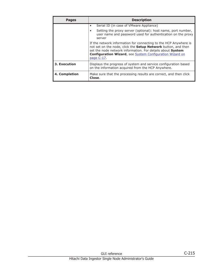
Pages Description
• Serial ID (in case of VMware Appliance)
• Setting the proxy server (optional): host name, port number,user name and password used for authentication on the proxyserver
If the network information for connecting to the HCP Anywhere isnot set on the node, click the Setup Network button, and thenset the node network information. For details about SystemConfiguration Wizard, see System Configuration Wizard onpage C-17.
3. Execution Displays the progress of system and service configuration basedon the information acquired from the HCP Anywhere.
4. Completion Make sure that the processing results are correct, and then clickClose.
GUI reference C-215Hitachi Data Ingestor Single Node Administrator's Guide

C-216 GUI referenceHitachi Data Ingestor Single Node Administrator's Guide

DOperation performed by end users
The end users registered by the local authentication, the NIS server, or theLDAP server (used for user authentication) can use the GUI to viewinformation such as information about file shares and quota information andchange the logon password. This appendix explains how to use the GUI as anend-user.
□ List of operations
□ Logging on
□ Basic GUI operations
□ GUI reference
Operation performed by end users D-1Hitachi Data Ingestor Single Node Administrator's Guide
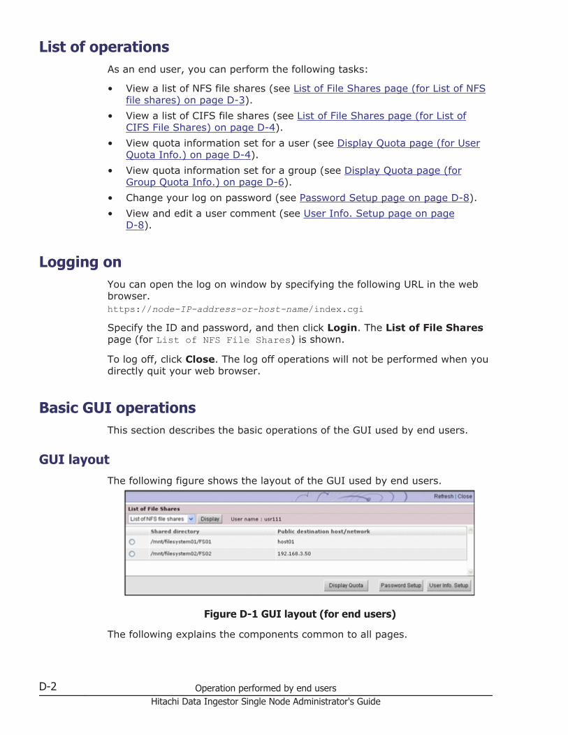
List of operationsAs an end user, you can perform the following tasks:
• View a list of NFS file shares (see List of File Shares page (for List of NFSfile shares) on page D-3).
• View a list of CIFS file shares (see List of File Shares page (for List ofCIFS File Shares) on page D-4).
• View quota information set for a user (see Display Quota page (for UserQuota Info.) on page D-4).
• View quota information set for a group (see Display Quota page (forGroup Quota Info.) on page D-6).
• Change your log on password (see Password Setup page on page D-8).
• View and edit a user comment (see User Info. Setup page on pageD-8).
Logging onYou can open the log on window by specifying the following URL in the webbrowser.https://node-IP-address-or-host-name/index.cgiSpecify the ID and password, and then click Login. The List of File Sharespage (for List of NFS File Shares) is shown.
To log off, click Close. The log off operations will not be performed when youdirectly quit your web browser.
Basic GUI operationsThis section describes the basic operations of the GUI used by end users.
GUI layoutThe following figure shows the layout of the GUI used by end users.
Figure D-1 GUI layout (for end users)
The following explains the components common to all pages.
D-2 Operation performed by end usersHitachi Data Ingestor Single Node Administrator's Guide
RefreshClick to refresh the information displayed in a page used to view a list orstatus. Although Refresh also appears in other pages, clicking Refreshin such pages does not refresh any information.
CloseClick to close the current window.
User nameName of the logged-on user.
Notes about using the GUINote the following points when you use the GUI:
• You will be forced to log off if you do not access the program for 30minutes or more during your log on session.
• When using a wheel mouse, do not rotate the wheel while pressing theShift key. This operation might cause the page to change to another andthe running operation to end abnormally. If an error occurs when usingthe wheel mouse and the Shift key, you must log off by clicking Close,and then log on again.If Close is not displayed, click the X on the title bar to close the window,and then log on again.
• Do not use the Web browser menu (or shortcuts) to perform anyoperations other than the following:
¢ Change text size
¢ Copy
¢ PastePerforming an operation other than those noted above might affect thebehavior of the GUI.
GUI referenceThis section describes the GUI windows used by end users.
List of File Shares page (for List of NFS file shares)In the List of File Shares page (for List of NFS File Shares), an enduser can view a list of NFS shares.
You can view the List of File Shares page (for List of NFS File Shares)by selecting List of NFS file shares in the drop-down list and thenclicking Display in the List of File Shares page.
The following table lists the information shown in the List of File Sharespage (for List of NFS File Shares).
Operation performed by end users D-3Hitachi Data Ingestor Single Node Administrator's Guide
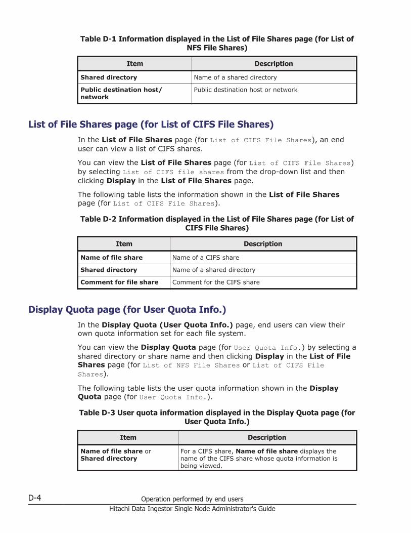
Table D-1 Information displayed in the List of File Shares page (for List ofNFS File Shares)
Item Description
Shared directory Name of a shared directory
Public destination host/network
Public destination host or network
List of File Shares page (for List of CIFS File Shares)In the List of File Shares page (for List of CIFS File Shares), an enduser can view a list of CIFS shares.
You can view the List of File Shares page (for List of CIFS File Shares)by selecting List of CIFS file shares from the drop-down list and thenclicking Display in the List of File Shares page.
The following table lists the information shown in the List of File Sharespage (for List of CIFS File Shares).
Table D-2 Information displayed in the List of File Shares page (for List ofCIFS File Shares)
Item Description
Name of file share Name of a CIFS share
Shared directory Name of a shared directory
Comment for file share Comment for the CIFS share
Display Quota page (for User Quota Info.)In the Display Quota (User Quota Info.) page, end users can view theirown quota information set for each file system.
You can view the Display Quota page (for User Quota Info.) by selecting ashared directory or share name and then clicking Display in the List of FileShares page (for List of NFS File Shares or List of CIFS FileShares).
The following table lists the user quota information shown in the DisplayQuota page (for User Quota Info.).
Table D-3 User quota information displayed in the Display Quota page (forUser Quota Info.)
Item Description
Name of file share orShared directory
For a CIFS share, Name of file share displays thename of the CIFS share whose quota information isbeing viewed.
D-4 Operation performed by end usersHitachi Data Ingestor Single Node Administrator's Guide
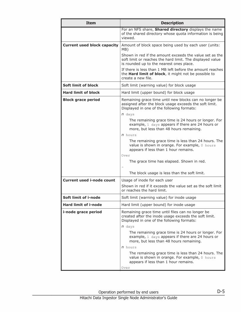
Item Description
For an NFS share, Shared directory displays the nameof the shared directory whose quota information is beingviewed.
Current used block capacity Amount of block space being used by each user (units:MB)
Shown in red if the amount exceeds the value set as thesoft limit or reaches the hard limit. The displayed valueis rounded up to the nearest ones place.
If there is less than 1 MB left before the amount reachesthe Hard limit of block, it might not be possible tocreate a new file.
Soft limit of block Soft limit (warning value) for block usage
Hard limit of block Hard limit (upper bound) for block usage
Block grace period Remaining grace time until new blocks can no longer beassigned after the block usage exceeds the soft limit.Displayed in one of the following formats:
n daysThe remaining grace time is 24 hours or longer. Forexample, 1 days appears if there are 24 hours ormore, but less than 48 hours remaining.
n hoursThe remaining grace time is less than 24 hours. Thevalue is shown in orange. For example, 0 hoursappears if less than 1 hour remains.
OverThe grace time has elapsed. Shown in red.
-The block usage is less than the soft limit.
Current used i-node count Usage of inode for each user
Shown in red if it exceeds the value set as the soft limitor reaches the hard limit.
Soft limit of i-node Soft limit (warning value) for inode usage
Hard limit of i-node Hard limit (upper bound) for inode usage
i-node grace period Remaining grace time until files can no longer becreated after the inode usage exceeds the soft limit.Displayed in one of the following formats:
n daysThe remaining grace time is 24 hours or longer. Forexample, 1 days appears if there are 24 hours ormore, but less than 48 hours remaining.
n hoursThe remaining grace time is less than 24 hours. Thevalue is shown in orange. For example, 0 hoursappears if less than 1 hour remains.
Over
Operation performed by end users D-5Hitachi Data Ingestor Single Node Administrator's Guide
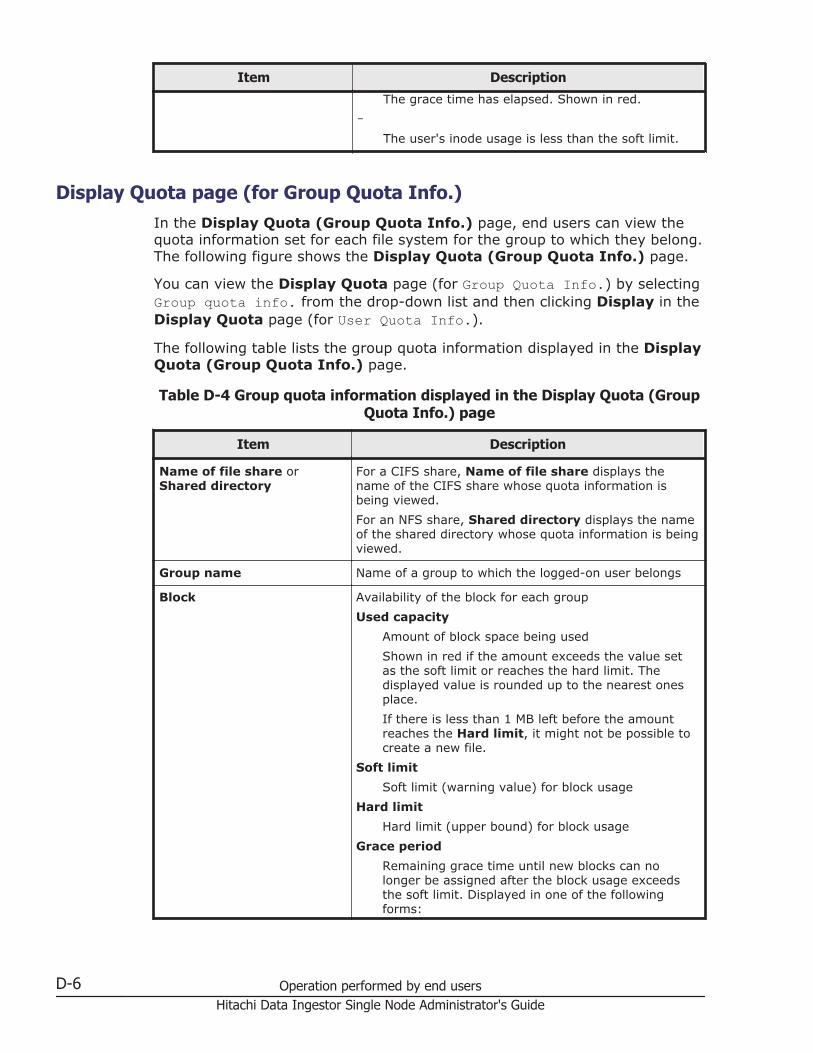
Item Description
The grace time has elapsed. Shown in red.
-The user's inode usage is less than the soft limit.
Display Quota page (for Group Quota Info.)In the Display Quota (Group Quota Info.) page, end users can view thequota information set for each file system for the group to which they belong.The following figure shows the Display Quota (Group Quota Info.) page.
You can view the Display Quota page (for Group Quota Info.) by selectingGroup quota info. from the drop-down list and then clicking Display in theDisplay Quota page (for User Quota Info.).
The following table lists the group quota information displayed in the DisplayQuota (Group Quota Info.) page.
Table D-4 Group quota information displayed in the Display Quota (GroupQuota Info.) page
Item Description
Name of file share orShared directory
For a CIFS share, Name of file share displays thename of the CIFS share whose quota information isbeing viewed.
For an NFS share, Shared directory displays the nameof the shared directory whose quota information is beingviewed.
Group name Name of a group to which the logged-on user belongs
Block Availability of the block for each group
Used capacity
Amount of block space being used
Shown in red if the amount exceeds the value setas the soft limit or reaches the hard limit. Thedisplayed value is rounded up to the nearest onesplace.
If there is less than 1 MB left before the amountreaches the Hard limit, it might not be possible tocreate a new file.
Soft limit
Soft limit (warning value) for block usage
Hard limit
Hard limit (upper bound) for block usage
Grace period
Remaining grace time until new blocks can nolonger be assigned after the block usage exceedsthe soft limit. Displayed in one of the followingforms:
D-6 Operation performed by end usersHitachi Data Ingestor Single Node Administrator's Guide
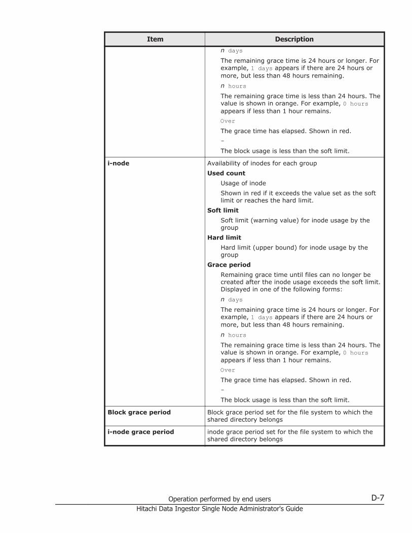
Item Description
n daysThe remaining grace time is 24 hours or longer. Forexample, 1 days appears if there are 24 hours ormore, but less than 48 hours remaining.
n hoursThe remaining grace time is less than 24 hours. Thevalue is shown in orange. For example, 0 hoursappears if less than 1 hour remains.
OverThe grace time has elapsed. Shown in red.
-The block usage is less than the soft limit.
i-node Availability of inodes for each group
Used count
Usage of inode
Shown in red if it exceeds the value set as the softlimit or reaches the hard limit.
Soft limit
Soft limit (warning value) for inode usage by thegroup
Hard limit
Hard limit (upper bound) for inode usage by thegroup
Grace period
Remaining grace time until files can no longer becreated after the inode usage exceeds the soft limit.Displayed in one of the following forms:
n daysThe remaining grace time is 24 hours or longer. Forexample, 1 days appears if there are 24 hours ormore, but less than 48 hours remaining.
n hoursThe remaining grace time is less than 24 hours. Thevalue is shown in orange. For example, 0 hoursappears if less than 1 hour remains.
OverThe grace time has elapsed. Shown in red.
-The block usage is less than the soft limit.
Block grace period Block grace period set for the file system to which theshared directory belongs
i-node grace period inode grace period set for the file system to which theshared directory belongs
Operation performed by end users D-7Hitachi Data Ingestor Single Node Administrator's Guide
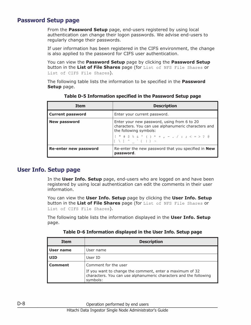
Password Setup pageFrom the Password Setup page, end-users registered by using localauthentication can change their logon passwords. We advise end-users toregularly change their passwords.
If user information has been registered in the CIFS environment, the changeis also applied to the password for CIFS user authentication.
You can view the Password Setup page by clicking the Password Setupbutton in the List of File Shares page (for List of NFS File Shares orList of CIFS File Shares).
The following table lists the information to be specified in the PasswordSetup page.
Table D-5 Information specified in the Password Setup page
Item Description
Current password Enter your current password.
New password Enter your new password, using from 6 to 20characters. You can use alphanumeric characters andthe following symbols:
! " # $ % & ' ( ) * + , - . / : ; < = > ? @[ \ ] ^ _ ` { | } ~
Re-enter new password Re-enter the new password that you specified in Newpassword.
User Info. Setup pageIn the User Info. Setup page, end-users who are logged on and have beenregistered by using local authentication can edit the comments in their userinformation.
You can view the User Info. Setup page by clicking the User Info. Setupbutton in the List of File Shares page (for List of NFS File Shares orList of CIFS File Shares).
The following table lists the information displayed in the User Info. Setuppage.
Table D-6 Information displayed in the User Info. Setup page
Item Description
User name User name
UID User ID
Comment Comment for the user
If you want to change the comment, enter a maximum of 32characters. You can use alphanumeric characters and the followingsymbols:
D-8 Operation performed by end usersHitachi Data Ingestor Single Node Administrator's Guide

Item Description# % & ' ( ) * + - . / ; < > ? @ [ ] ^ _ { | } ~You can also specify spaces, but spaces cannot be specified at thebeginning nor at the end of the character string. If you leave thisitem blank, no comment is entered.
Operation performed by end users D-9Hitachi Data Ingestor Single Node Administrator's Guide

D-10 Operation performed by end usersHitachi Data Ingestor Single Node Administrator's Guide
EReserved words
This appendix lists the words reserved by the system.
□ List of reserved words
Reserved words E-1Hitachi Data Ingestor Single Node Administrator's Guide
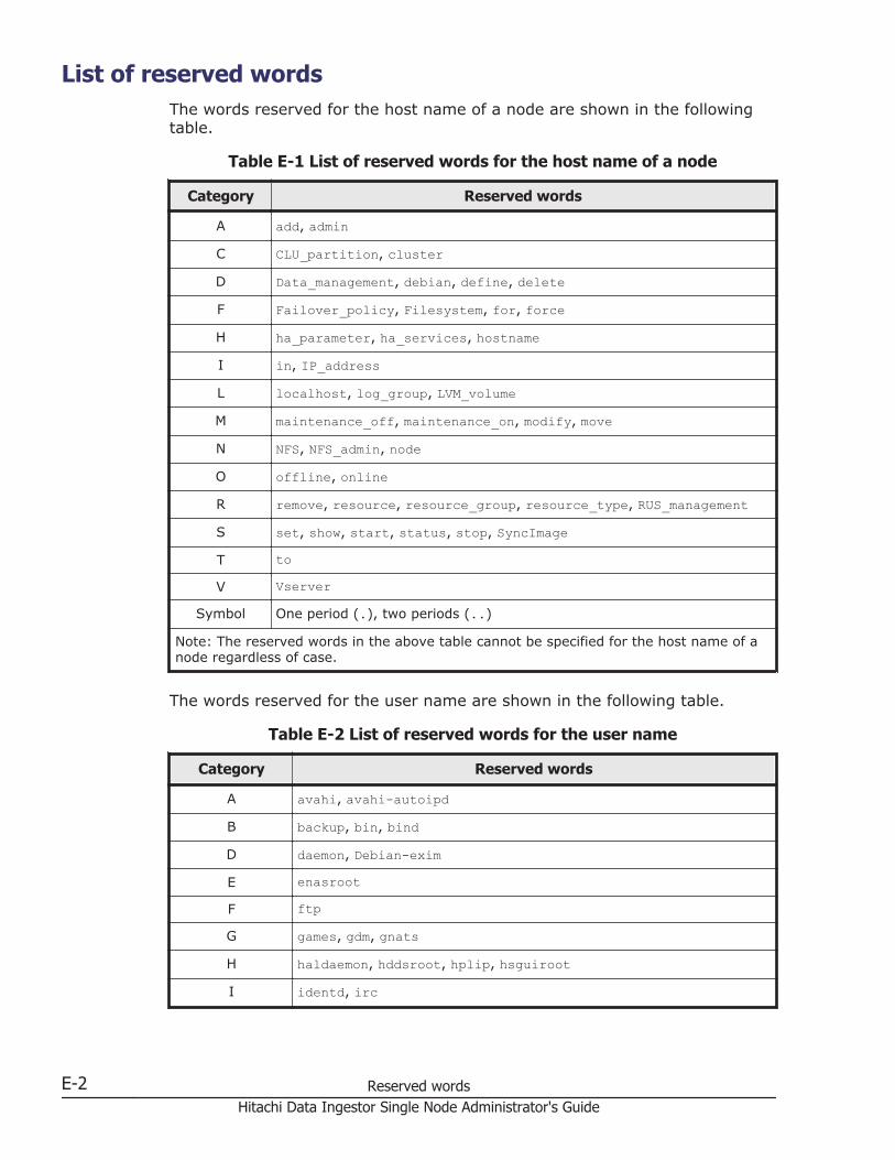
List of reserved wordsThe words reserved for the host name of a node are shown in the followingtable.
Table E-1 List of reserved words for the host name of a node
Category Reserved words
A add, admin
C CLU_partition, cluster
D Data_management, debian, define, delete
F Failover_policy, Filesystem, for, force
H ha_parameter, ha_services, hostname
I in, IP_address
L localhost, log_group, LVM_volume
M maintenance_off, maintenance_on, modify, move
N NFS, NFS_admin, node
O offline, online
R remove, resource, resource_group, resource_type, RUS_management
S set, show, start, status, stop, SyncImage
T to
V Vserver
Symbol One period (.), two periods (..)
Note: The reserved words in the above table cannot be specified for the host name of anode regardless of case.
The words reserved for the user name are shown in the following table.
Table E-2 List of reserved words for the user name
Category Reserved words
A avahi, avahi-autoipd
B backup, bin, bind
D daemon, Debian-exim
E enasroot
F ftp
G games, gdm, gnats
H haldaemon, hddsroot, hplip, hsguiroot
I identd, irc
E-2 Reserved wordsHitachi Data Ingestor Single Node Administrator's Guide
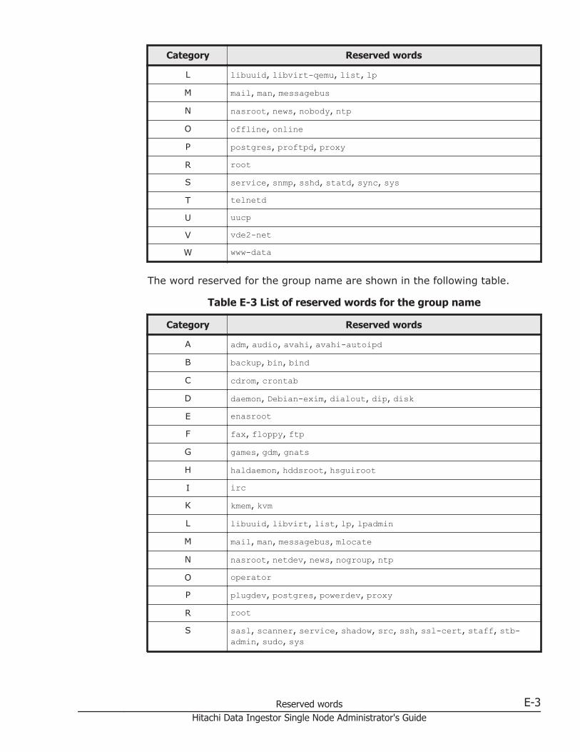
Category Reserved words
L libuuid, libvirt-qemu, list, lp
M mail, man, messagebus
N nasroot, news, nobody, ntp
O offline, online
P postgres, proftpd, proxy
R root
S service, snmp, sshd, statd, sync, sys
T telnetd
U uucp
V vde2-net
W www-data
The word reserved for the group name are shown in the following table.
Table E-3 List of reserved words for the group name
Category Reserved words
A adm, audio, avahi, avahi-autoipd
B backup, bin, bind
C cdrom, crontab
D daemon, Debian-exim, dialout, dip, disk
E enasroot
F fax, floppy, ftp
G games, gdm, gnats
H haldaemon, hddsroot, hsguiroot
I irc
K kmem, kvm
L libuuid, libvirt, list, lp, lpadmin
M mail, man, messagebus, mlocate
N nasroot, netdev, news, nogroup, ntp
O operator
P plugdev, postgres, powerdev, proxy
R root
S sasl, scanner, service, shadow, src, ssh, ssl-cert, staff, stb-admin, sudo, sys
Reserved words E-3Hitachi Data Ingestor Single Node Administrator's Guide
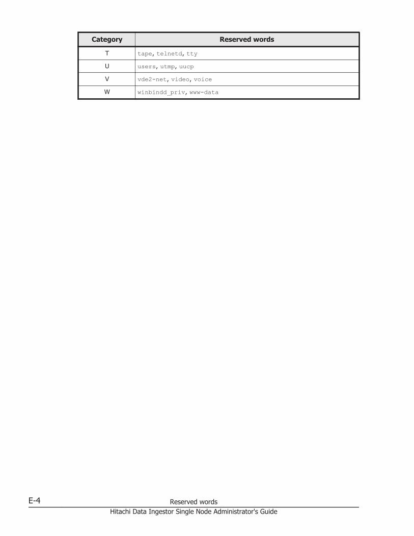
Category Reserved words
T tape, telnetd, tty
U users, utmp, uucp
V vde2-net, video, voice
W winbindd_priv, www-data
E-4 Reserved wordsHitachi Data Ingestor Single Node Administrator's Guide
FMIB objects
This appendix explains SNMP MIB objects used in the HDI system.
□ List of MIB objects
□ MIB objects for responding to SNMP get requests
□ MIB objects used for SNMP traps
MIB objects F-1Hitachi Data Ingestor Single Node Administrator's Guide
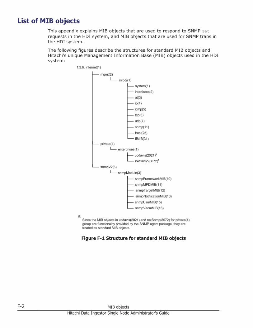
List of MIB objectsThis appendix explains MIB objects that are used to respond to SNMP getrequests in the HDI system, and MIB objects that are used for SNMP traps inthe HDI system.
The following figures describe the structures for standard MIB objects andHitachi's unique Management Information Base (MIB) objects used in the HDIsystem:
Figure F-1 Structure for standard MIB objects
F-2 MIB objectsHitachi Data Ingestor Single Node Administrator's Guide

Figure F-2 Groups of MIB objects for responding to SNMP get requests andtables to be referenced (standard MIB objects)
MIB objects for responding to SNMP get requestsThe following table lists the environments in which the MIB objects in an HDIsystem that are used to respond to SNMP get requests can be obtained andthe tables to be referenced.
Table F-1 Environments in which the MIB objects used to respond to SNMPget requests can be obtained and the tables to be referenced (standard
MIB objects)
Group nameDefinition
RFCnumber
Description Tables
1.3.6.1.2.mib-2(1)
system (1) 1907 This group is forsysteminformation.
Table F-3 system(1) group on pageF-6
interfaces (2) 1213 This group is forinterfacesinformation.
Table F-4interfaces (2)group on pageF-6
at (3) 1213 This group is for atinformation.
Table F-5 at (3)group on pageF-8
ip (4) 1213 This group is for ipinformation.
Table F-6 ip (4)group on pageF-8
MIB objects F-3Hitachi Data Ingestor Single Node Administrator's Guide
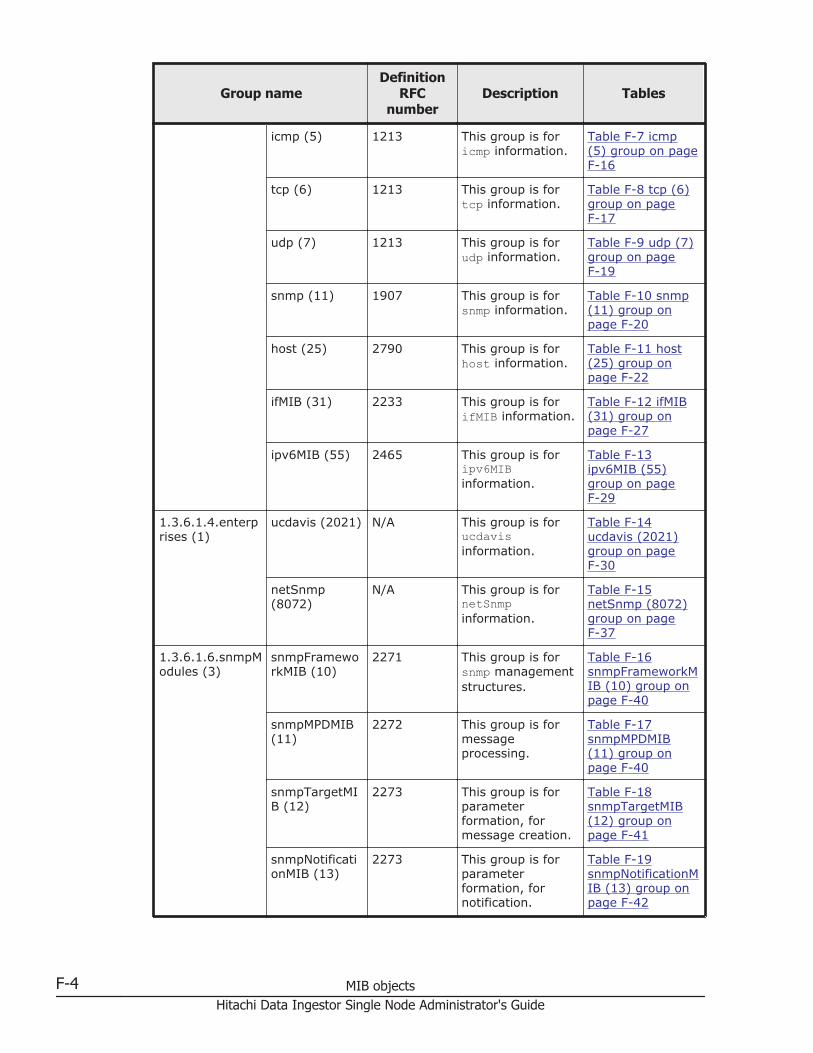
Group nameDefinition
RFCnumber
Description Tables
icmp (5) 1213 This group is foricmp information.
Table F-7 icmp(5) group on pageF-16
tcp (6) 1213 This group is fortcp information.
Table F-8 tcp (6)group on pageF-17
udp (7) 1213 This group is forudp information.
Table F-9 udp (7)group on pageF-19
snmp (11) 1907 This group is forsnmp information.
Table F-10 snmp(11) group onpage F-20
host (25) 2790 This group is forhost information.
Table F-11 host(25) group onpage F-22
ifMIB (31) 2233 This group is forifMIB information.
Table F-12 ifMIB(31) group onpage F-27
ipv6MIB (55) 2465 This group is foripv6MIBinformation.
Table F-13ipv6MIB (55)group on pageF-29
1.3.6.1.4.enterprises (1)
ucdavis (2021) N/A This group is forucdavisinformation.
Table F-14ucdavis (2021)group on pageF-30
netSnmp(8072)
N/A This group is fornetSnmpinformation.
Table F-15netSnmp (8072)group on pageF-37
1.3.6.1.6.snmpModules (3)
snmpFrameworkMIB (10)
2271 This group is forsnmp managementstructures.
Table F-16snmpFrameworkMIB (10) group onpage F-40
snmpMPDMIB(11)
2272 This group is formessageprocessing.
Table F-17snmpMPDMIB(11) group onpage F-40
snmpTargetMIB (12)
2273 This group is forparameterformation, formessage creation.
Table F-18snmpTargetMIB(12) group onpage F-41
snmpNotificationMIB (13)
2273 This group is forparameterformation, fornotification.
Table F-19snmpNotificationMIB (13) group onpage F-42
F-4 MIB objectsHitachi Data Ingestor Single Node Administrator's Guide

Group nameDefinition
RFCnumber
Description Tables
snmpUsmMIB(15)
2274 This group is forsecurityinformationdefinition.
Table F-20snmpUsmMIB(15) group onpage F-43
snmpVacmMIB(16)
2275 This group is foraccess/controlinformationdefinition.
Table F-21snmpVacmMIB(16) group onpage F-44
Note: N/A = Not applicable.
Table F-2 Environments in which the MIB objects used to respond to SNMPget requests can be obtained and the tables to be referenced (Hitachi MIB
objects)
Group name Description Tables
stdExMibVersion (1) This group is for versioninformation.
Not applicable
stdExMibQuotaTable (2) This group is for quotamanagement.
Table F-22stdExMibQuotaTable (2)group on page F-46
stdExMibNfs (4) This group is for NFS. Table F-23 stdExMibNfs (4)group on page F-53
stdExMibCifs (5) This group is for CIFS. Table F-24 stdExMibCifs (5)group on page F-61
stdExMibNetwork (6) This group is for thenetwork.
Table F-25 stdExMibNetwork(6) group on page F-61
stdExMibPerformManager(7)
This group is forperformance management.
Table F-26stdExMibPerformManager (7)group on page F-62
stdExMibFileSystem (11) This group is for filesystems.
Table F-27stdExMibFileSystem (11)group on page F-63
stdExMibHDPPool (12) This group is for pools. Table F-28 stdExMibHDPPool(12) group on page F-65
Tables Table F-3 system (1) group on page F-6 to Table F-28stdExMibHDPPool (12) group on page F-65 summarize the groups of MIBobjects used in responding to SNMP get requests. In the tables, the type isdescribed as - for the MIB objects that have no data types and have Entrytypes (which are in table structure and therefore cannot be accessed).
MIB objects F-5Hitachi Data Ingestor Single Node Administrator's Guide

Table F-3 system (1) group
ID Object name Type Meaning
1 sysDescr (1) DisplayString Names or version numbers for thehardware, OS, and network OS.
2 sysObjectID (2) OBJECTIDENTIFIER
Vendor authentication ID for the networkmanagement subsystem.
3 sysUpTime (3) TimeTicks Time elapsed since system startup.
4 sysContact (4) DisplayString Contact information for the managementnode.
5 sysName (5) DisplayString The name and domain name of themanagement node.
6 sysLocation (6) DisplayString Location in which the management nodeis set up.
7 sysServices (7) INTEGER A value indicating services.
8 sysORLastChange (8) TimeTicks The latest value for sysUpTime.
9 sysORTable (9) - For each MIB module, lists the functionsof the local SNMPv2 entity acting as anagent.
9.1 sysOREntry (1) - Contains sysORTable entries.
9.1.1 sysORIndex (1) INTEGER A support variable used to identifyinstances of sysORTable columns andobjects.
This cannot be obtained.
9.1.2 sysORID (2) OBJECTIDENTIFIER
Indicates proper identifiers for each MIBmodule.
MIB modules are supported based on thelocal SNMPv2 entity acting as an agent.
9.1.3 sysORDescr (3) DisplayString Defines a text description of the functionidentified by the corresponding sysORID.
9.1.4 sysORUpTime (4) TimeStamp Indicates the value of sysUpTime at thetime this overview row was lastinstantiated.
Table F-4 interfaces (2) group
ID Object name Type Meaning
1 ifNumber (1) Integer32 The number of network interfaces providedby the system
2 ifTable (2) - The interface entity table
2.1 ifEntry (1) - A list of interface information belonging tothe sub-network layer
2.1.1 ifIndex (1) InterfaceIndex A number identifying this interface (valuesare sequential, from 1 to ifNumber)
F-6 MIB objectsHitachi Data Ingestor Single Node Administrator's Guide

ID Object name Type Meaning
2.1.2 ifDescr (2) DisplayString Information about the interface
2.1.3 ifType (3) IANAifType The interface type
2.1.4 ifMtu (4) Integer32 The maximum size of datagrams that canbe transmitted with this interface
2.1.5 ifSpeed (5) Gauge32 An estimate of the current line speed forthis interface#1
2.1.6 ifPhysAddress (6) PhysAddress The physical address immediately belowthe network layer of this interface
2.1.7 ifAdminStatus (7) INTEGER The desired status for this interface
Each value represents the following:
1: up, 2: down, 3: testing
2.1.8 ifOperStatus (8) INTEGER The current status of this interface
Each value represents the following:
1: up, 2: down, 3: testing, 4: unknown, 5:dormant, 6: notPresent, 7:lowerLayerDown
2.1.9 ifLastChange (9) TimeTicks The value of sysUpTime at the time atwhich ifOperStatus was last changed forthis interface
2.1.10 ifInOctets (10) Counter32 The number of octets received with thisinterface#2
2.1.11 ifInUcastPkts (11) Counter32 The number of unicast packets for whichthe upper protocol has been notified#3
2.1.12 ifInNUcastPkts(12)
Counter32 The number of non-unicast packets(broadcast or multicast packets) for whichthe upper protocol has been notified
2.1.13 ifInDiscards (13) Counter32 The number of packets for which no errorsoccurred, but nevertheless could not bepassed to the upper protocol (the numberof incoming packets that were discarded,with no buffer, etc.)
2.1.14 ifInErrors (14) Counter32 The number of packets that could not bereceived because an error occurred withinthe packet
2.1.15 ifInUnknownProtos(15)
Counter32 The number of packets discarded, becauseof receiving unsupported protocol
2.1.16 ifOutOctets (16) Counter32 The number of octets from packetstransmitted with this interface#2
2.1.17 ifOutUcastPkts(17)
Counter32 The number of unicast packets sent by theupper layer#3
2.1.18 ifOutNUcastPkts(18)
Counter32 The number of non-unicast packets sentby the upper layer
MIB objects F-7Hitachi Data Ingestor Single Node Administrator's Guide

ID Object name Type Meaning
2.1.19 ifOutDiscards (19) Counter32 The number of packets with no errors, butthat were discarded during transmissionprocessing (for which the transmissionbuffer was insufficient, and so on.)
2.1.20 ifOutErrors (20) Counter32 The number of packets that could not besent because of an error
2.1.21 ifOutQLen (21) Gauge32 The size of the queue for transmissionpackets
2.1.22 ifSpecific (22) OBJECTIDENTIFIER
A reference to a MIB defining properties ofthe interface media
The object ID of a MIB is dependent onifType
#1: The estimated line speed for a GbE interface is 100,000,000 bps. This is the valueoutput by standard MIBs for GbE interfaces. The estimated line speed for trunking-portinterfaces is not close to the actual value. The estimated value for a trunking port isalways set to 100,000,000.
#2: ifInOctets and ifOutOctets are 32-bit counters, and are reset if there is 100 Mbps oftraffic within 5 minutes.
#3: ifInUcastPkts and ifOutUcastPkts are 32-bit counters, and might be reset if thesystem is continuously run for a long time.
Table F-5 at (3) group
ID Object name Type Meaning
1 atTable (1) - The table for NetworkAddress for thecorresponding value of the physical address
1.1 atEntry (1) - A list related to one NetworkAddress forthe corresponding value of the physicaladdress for each entry
1.1.1 atIfIndex (1) INTEGER The value of ifIndex for the correspondinginterface
1.1.2 atPhysAddress (2) PhysAddress The physical address
1.1.3 atNetAddress (3) NetworkAddress
The IP address corresponding toatPhysAddress, depending on the media
Table F-6 ip (4) group
ID Object name Type Meaning
1 ipForwarding (1) INTEGER Availability of IP relay functionality(whether or not operation is performedby gateway)
Each value represents the following:
1: forwarding, 2: notForwarding
2 ipDefaultTTL (2) Integer32 The default TTL setting in IP headers
F-8 MIB objectsHitachi Data Ingestor Single Node Administrator's Guide

ID Object name Type Meaning
3 ipInReceives (3) Counter32 The total number of IP datagramsreceived from all interfaces
4 ipInHdrErrors (4) Counter32 The number of datagrams received andthen discarded because of IP headererrors
5 ipInAddrErrors (5) Counter32 The number of packets discardedbecause of an invalid destinationaddress in the IP header
6 ipForwDatagrams (6) Counter32 The number of packets for which relaywas deemed necessary
7 ipInUnknownProtos(7)
Counter32 The number of IP data programsdiscarded because of the following:
• The protocol cannot be confirmedfor incoming IP packets.
• The protocol is unsupported.
8 ipInDiscards (8) Counter32 The total number of IP datagramsdiscarded during transmission forreasons other than errors
9 ipInDelivers (9) Counter32 The number of IP datagrams reportedto the upper layer
10 ipOutRequests (10) Counter32 The total number of IP datagramsrequested by the upper layer, for IPpacket transmission
11 ipOutDiscards (11) Counter32 The number of IP datagrams discardedfor reasons other than errors
12 ipOutNoRoutes (12) Counter32 The number of IP datagrams discardedbecause no transmission route wasspecified
13 ipReasmTimeout (13) Integer32 The maximum number of seconds tohold fragment packets waiting forreassembly
14 ipReasmReqds (14) Counter32 The number of incoming IP datagramsfor which reassembly is necessary
15 ipReasmOKs (15) Counter32 The number of incoming IP datagramsfor which reassembly was successful
16 ipReasmFails (16) Counter32 The number of incoming IP datagramsfor which reassembly failed
17 ipFragOKs (17) Counter32 The number of IP datagrams for whichfragmentation was successful
18 ipFragFails (18) Counter32 The number of IP datagrams for whichfragmentation failed
19 ipFragCreates (19) Counter32 The number of IP datagram fragmentscreated as a result of fragmentation
20 ipAddrTable (20) - A table for addressing informationrelated to the IP address of this entity
MIB objects F-9Hitachi Data Ingestor Single Node Administrator's Guide
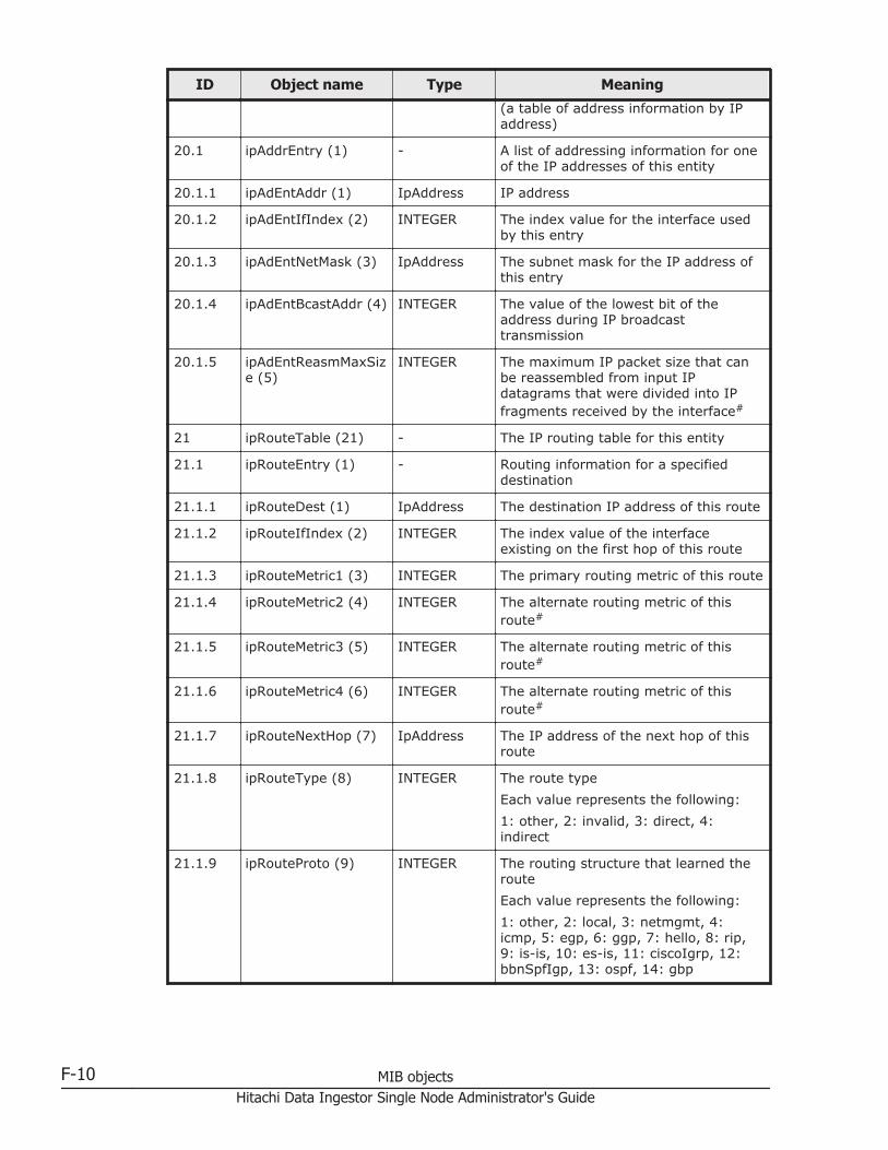
ID Object name Type Meaning
(a table of address information by IPaddress)
20.1 ipAddrEntry (1) - A list of addressing information for oneof the IP addresses of this entity
20.1.1 ipAdEntAddr (1) IpAddress IP address
20.1.2 ipAdEntIfIndex (2) INTEGER The index value for the interface usedby this entry
20.1.3 ipAdEntNetMask (3) IpAddress The subnet mask for the IP address ofthis entry
20.1.4 ipAdEntBcastAddr (4) INTEGER The value of the lowest bit of theaddress during IP broadcasttransmission
20.1.5 ipAdEntReasmMaxSize (5)
INTEGER The maximum IP packet size that canbe reassembled from input IPdatagrams that were divided into IPfragments received by the interface#
21 ipRouteTable (21) - The IP routing table for this entity
21.1 ipRouteEntry (1) - Routing information for a specifieddestination
21.1.1 ipRouteDest (1) IpAddress The destination IP address of this route
21.1.2 ipRouteIfIndex (2) INTEGER The index value of the interfaceexisting on the first hop of this route
21.1.3 ipRouteMetric1 (3) INTEGER The primary routing metric of this route
21.1.4 ipRouteMetric2 (4) INTEGER The alternate routing metric of thisroute#
21.1.5 ipRouteMetric3 (5) INTEGER The alternate routing metric of thisroute#
21.1.6 ipRouteMetric4 (6) INTEGER The alternate routing metric of thisroute#
21.1.7 ipRouteNextHop (7) IpAddress The IP address of the next hop of thisroute
21.1.8 ipRouteType (8) INTEGER The route type
Each value represents the following:
1: other, 2: invalid, 3: direct, 4:indirect
21.1.9 ipRouteProto (9) INTEGER The routing structure that learned theroute
Each value represents the following:
1: other, 2: local, 3: netmgmt, 4:icmp, 5: egp, 6: ggp, 7: hello, 8: rip,9: is-is, 10: es-is, 11: ciscoIgrp, 12:bbnSpfIgp, 13: ospf, 14: gbp
F-10 MIB objectsHitachi Data Ingestor Single Node Administrator's Guide

ID Object name Type Meaning
21.1.10 ipRouteAge (10) INTEGER The amount of time elapsed since theroute was updated#
21.1.11 ipRouteMask (11) IpAddress The subnet mask value foripRouteDest
21.1.12 ipRouteMetric5 (12) INTEGER The alternate routing metric of thisroute#
21.1.13 ipRouteInfo (13) OBJECTIDENTIFIER
A reference to the MIB object definingthe specific routing protocol that can betrusted on this route
22 ipNetToMediaTable(22)
- The IP address conversion table used tomap a physical address from IPaddresses
22.1 ipNetToMediaEntry(1)
- A list of individual IP addresses thatcorrespond to the physical address
22.1.1 ipNetToMediaIfIndex(1)
INTEGER The ID number of the active interface
22.1.2 ipNetToMediaPhysAddress (2)
INTEGER The media-dependent physical address
22.1.3 ipNetToMediaNetAddress (3)
PhysAddress The IP address corresponding to themedia-dependent physical address
22.1.4 ipNetToMediaType(4)
INTEGER The mapping type
Each value represents the following:
1: other, 2: invalid, 3: dynamic, 4:static
23 ipRoutingDiscards(23)
Counter The number of routing entries selectedfor rejection despite being active, suchas those rejected because of aninsufficient buffer for the routing table
24 ipForward (24) - The MIB module for the managementof CIDR multipath IP Routes
24.4 ipCidrRouteTable (4) - The IP CIDR entity's IP Routing table
24.4.1 ipCidrRouteDest (1) IpAddress The destination IP address
24.4.2 ipCidrRouteMask (2) IpAddress The IP address and the mask value
24.4.3 ipCidrRouteTos (3) Integer32 The IP TOS Field
24.4.4 ipCidrRouteNextHop(4)
IpAddress On remote routes, the address of thenext system en route
24.4.5 ipCidrRouteIfIndex(5)
Integer32 The index value of the local interface
24.4.6 ipCidrRouteType (6) INTEGER The type of route
Each value represents the following:
1: other, 2: reject, 3: local, 4: remote
MIB objects F-11Hitachi Data Ingestor Single Node Administrator's Guide
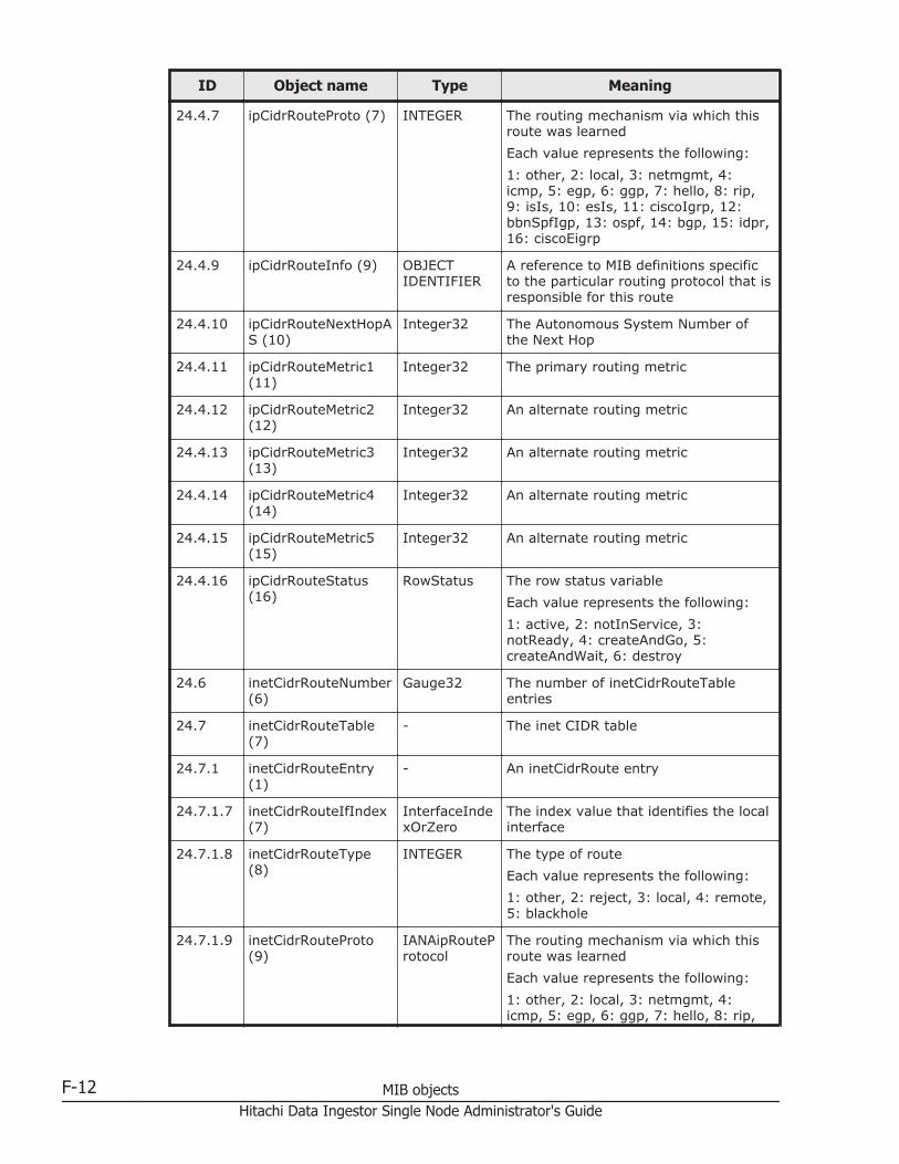
ID Object name Type Meaning
24.4.7 ipCidrRouteProto (7) INTEGER The routing mechanism via which thisroute was learned
Each value represents the following:
1: other, 2: local, 3: netmgmt, 4:icmp, 5: egp, 6: ggp, 7: hello, 8: rip,9: isIs, 10: esIs, 11: ciscoIgrp, 12:bbnSpfIgp, 13: ospf, 14: bgp, 15: idpr,16: ciscoEigrp
24.4.9 ipCidrRouteInfo (9) OBJECTIDENTIFIER
A reference to MIB definitions specificto the particular routing protocol that isresponsible for this route
24.4.10 ipCidrRouteNextHopAS (10)
Integer32 The Autonomous System Number ofthe Next Hop
24.4.11 ipCidrRouteMetric1(11)
Integer32 The primary routing metric
24.4.12 ipCidrRouteMetric2(12)
Integer32 An alternate routing metric
24.4.13 ipCidrRouteMetric3(13)
Integer32 An alternate routing metric
24.4.14 ipCidrRouteMetric4(14)
Integer32 An alternate routing metric
24.4.15 ipCidrRouteMetric5(15)
Integer32 An alternate routing metric
24.4.16 ipCidrRouteStatus(16)
RowStatus The row status variable
Each value represents the following:
1: active, 2: notInService, 3:notReady, 4: createAndGo, 5:createAndWait, 6: destroy
24.6 inetCidrRouteNumber(6)
Gauge32 The number of inetCidrRouteTableentries
24.7 inetCidrRouteTable(7)
- The inet CIDR table
24.7.1 inetCidrRouteEntry(1)
- An inetCidrRoute entry
24.7.1.7 inetCidrRouteIfIndex(7)
InterfaceIndexOrZero
The index value that identifies the localinterface
24.7.1.8 inetCidrRouteType(8)
INTEGER The type of route
Each value represents the following:
1: other, 2: reject, 3: local, 4: remote,5: blackhole
24.7.1.9 inetCidrRouteProto(9)
IANAipRouteProtocol
The routing mechanism via which thisroute was learned
Each value represents the following:
1: other, 2: local, 3: netmgmt, 4:icmp, 5: egp, 6: ggp, 7: hello, 8: rip,
F-12 MIB objectsHitachi Data Ingestor Single Node Administrator's Guide
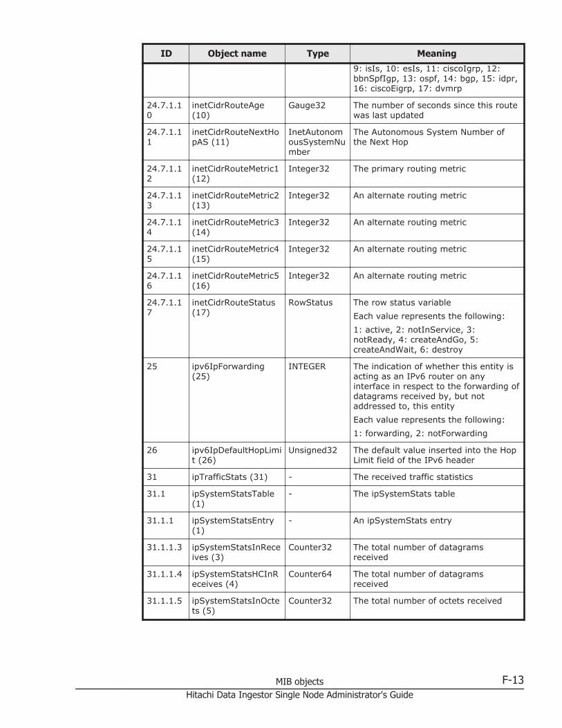
ID Object name Type Meaning
9: isIs, 10: esIs, 11: ciscoIgrp, 12:bbnSpfIgp, 13: ospf, 14: bgp, 15: idpr,16: ciscoEigrp, 17: dvmrp
24.7.1.10
inetCidrRouteAge(10)
Gauge32 The number of seconds since this routewas last updated
24.7.1.11
inetCidrRouteNextHopAS (11)
InetAutonomousSystemNumber
The Autonomous System Number ofthe Next Hop
24.7.1.12
inetCidrRouteMetric1(12)
Integer32 The primary routing metric
24.7.1.13
inetCidrRouteMetric2(13)
Integer32 An alternate routing metric
24.7.1.14
inetCidrRouteMetric3(14)
Integer32 An alternate routing metric
24.7.1.15
inetCidrRouteMetric4(15)
Integer32 An alternate routing metric
24.7.1.16
inetCidrRouteMetric5(16)
Integer32 An alternate routing metric
24.7.1.17
inetCidrRouteStatus(17)
RowStatus The row status variable
Each value represents the following:
1: active, 2: notInService, 3:notReady, 4: createAndGo, 5:createAndWait, 6: destroy
25 ipv6IpForwarding(25)
INTEGER The indication of whether this entity isacting as an IPv6 router on anyinterface in respect to the forwarding ofdatagrams received by, but notaddressed to, this entity
Each value represents the following:
1: forwarding, 2: notForwarding
26 ipv6IpDefaultHopLimit (26)
Unsigned32 The default value inserted into the HopLimit field of the IPv6 header
31 ipTrafficStats (31) - The received traffic statistics
31.1 ipSystemStatsTable(1)
- The ipSystemStats table
31.1.1 ipSystemStatsEntry(1)
- An ipSystemStats entry
31.1.1.3 ipSystemStatsInReceives (3)
Counter32 The total number of datagramsreceived
31.1.1.4 ipSystemStatsHCInReceives (4)
Counter64 The total number of datagramsreceived
31.1.1.5 ipSystemStatsInOctets (5)
Counter32 The total number of octets received
MIB objects F-13Hitachi Data Ingestor Single Node Administrator's Guide

ID Object name Type Meaning
31.1.1.6 ipSystemStatsHCInOctets (6)
Counter64 The total number of octets received
31.1.1.7 ipSystemStatsInHdrErrors (7)
Counter64 The number of datagrams discardedbecause of errors in their IP headers
31.1.1.9 ipSystemStatsInAddrErrors (9)
Counter32 The number of datagrams discardedbecause the IP address in their IPheader's destination field was not avalid address
31.1.1.10
ipSystemStatsInUnknownProtos (10)
Counter32 The number of datagrams receivedsuccessfully but discarded because ofan unknown or unsupported protocol
31.1.1.12
ipSystemStatsInForwDatagrams (12)
Counter32 The number of IP datagrams for whichthis entity was not their final IPdestination and for which this entityattempted to find a route to forwardthem to that final destination
31.1.1.13
ipSystemStatsHCInForwDatagrams (13)
Counter64 The number of IP datagrams for whichthis entity was not their final IPdestination and for which this entityattempted to find a route to forwardthem to that final destination
31.1.1.14
ipSystemStatsReasmReqds (14)
Counter32 The number of IP fragments receivedthat needed to be reassembled
31.1.1.15
ipSystemStatsReasmOKs (15)
Counter32 The number of IP datagramssuccessfully reassembled
31.1.1.16
ipSystemStatsReasmFails (16)
Counter32 The number of failures detected by theIP re-assembly algorithm
31.1.1.17
ipSystemStatsInDiscards (17)
Counter32 The number of input IP datagrams forwhich no problems were encounteredto prevent their continued processing,but were discarded
31.1.1.18
ipSystemStatsInDelivers (18)
Counter32 The total number of IP datagramssuccessfully delivered
31.1.1.20
ipSystemStatsOutRequests (20)
Counter32 The total number of IP datagramstransmitted
31.1.1.21
ipSystemStatsHCOutRequests (21)
Counter64 The total number of IP datagramstransmitted
31.1.1.22
ipSystemStatsOutNoRoutes (22)
Counter32 The number of IP datagrams discarded
31.1.1.24
ipSystemStatsHCOutForwDatagrams (24)
Counter64 The number of datagrams for whichthis entity was not their final IPdestination and for which it wassuccessful in finding a path to their finaldestination
31.1.1.25
ipSystemStatsOutDiscards (25)
Counter32 The number of output IP datagrams forwhich no problem was encountered to
F-14 MIB objectsHitachi Data Ingestor Single Node Administrator's Guide
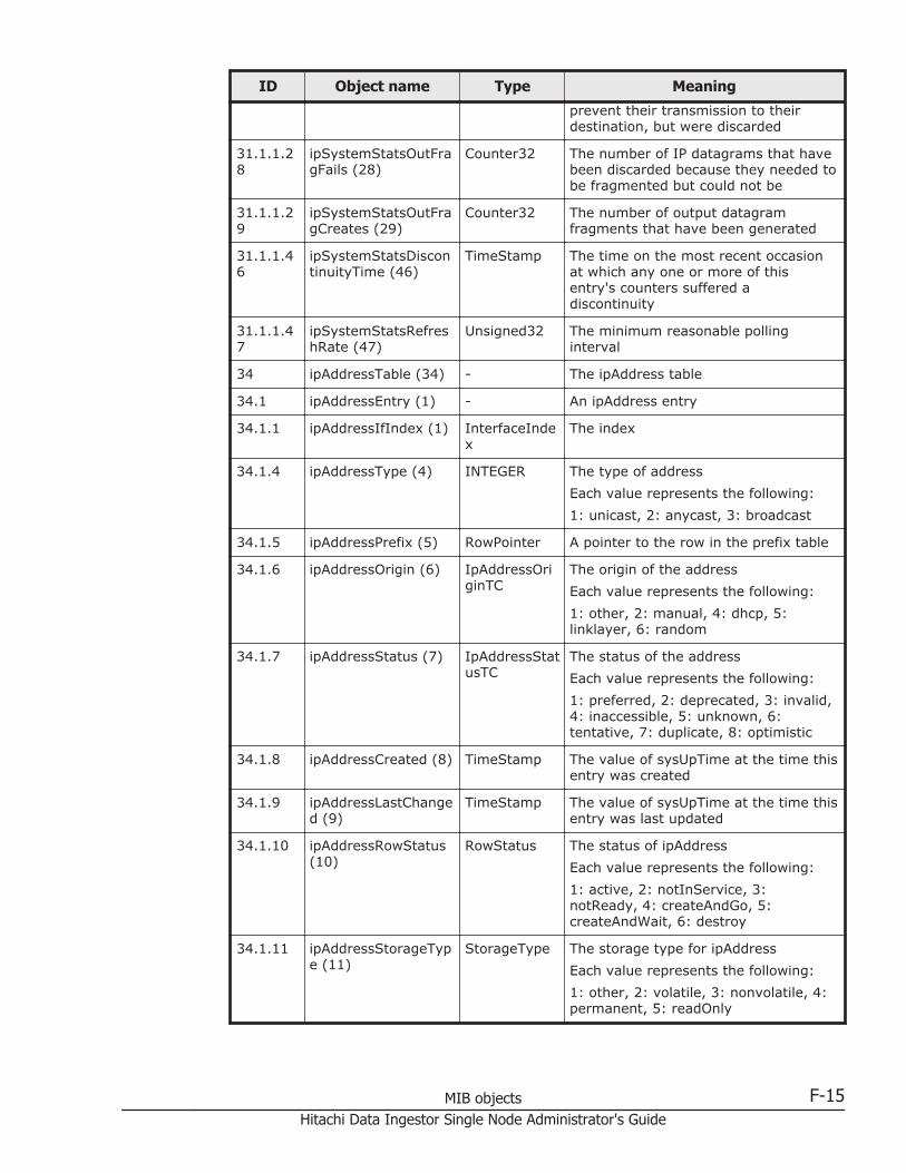
ID Object name Type Meaning
prevent their transmission to theirdestination, but were discarded
31.1.1.28
ipSystemStatsOutFragFails (28)
Counter32 The number of IP datagrams that havebeen discarded because they needed tobe fragmented but could not be
31.1.1.29
ipSystemStatsOutFragCreates (29)
Counter32 The number of output datagramfragments that have been generated
31.1.1.46
ipSystemStatsDiscontinuityTime (46)
TimeStamp The time on the most recent occasionat which any one or more of thisentry's counters suffered adiscontinuity
31.1.1.47
ipSystemStatsRefreshRate (47)
Unsigned32 The minimum reasonable pollinginterval
34 ipAddressTable (34) - The ipAddress table
34.1 ipAddressEntry (1) - An ipAddress entry
34.1.1 ipAddressIfIndex (1) InterfaceIndex
The index
34.1.4 ipAddressType (4) INTEGER The type of address
Each value represents the following:
1: unicast, 2: anycast, 3: broadcast
34.1.5 ipAddressPrefix (5) RowPointer A pointer to the row in the prefix table
34.1.6 ipAddressOrigin (6) IpAddressOriginTC
The origin of the address
Each value represents the following:
1: other, 2: manual, 4: dhcp, 5:linklayer, 6: random
34.1.7 ipAddressStatus (7) IpAddressStatusTC
The status of the address
Each value represents the following:
1: preferred, 2: deprecated, 3: invalid,4: inaccessible, 5: unknown, 6:tentative, 7: duplicate, 8: optimistic
34.1.8 ipAddressCreated (8) TimeStamp The value of sysUpTime at the time thisentry was created
34.1.9 ipAddressLastChanged (9)
TimeStamp The value of sysUpTime at the time thisentry was last updated
34.1.10 ipAddressRowStatus(10)
RowStatus The status of ipAddress
Each value represents the following:
1: active, 2: notInService, 3:notReady, 4: createAndGo, 5:createAndWait, 6: destroy
34.1.11 ipAddressStorageType (11)
StorageType The storage type for ipAddress
Each value represents the following:
1: other, 2: volatile, 3: nonvolatile, 4:permanent, 5: readOnly
MIB objects F-15Hitachi Data Ingestor Single Node Administrator's Guide
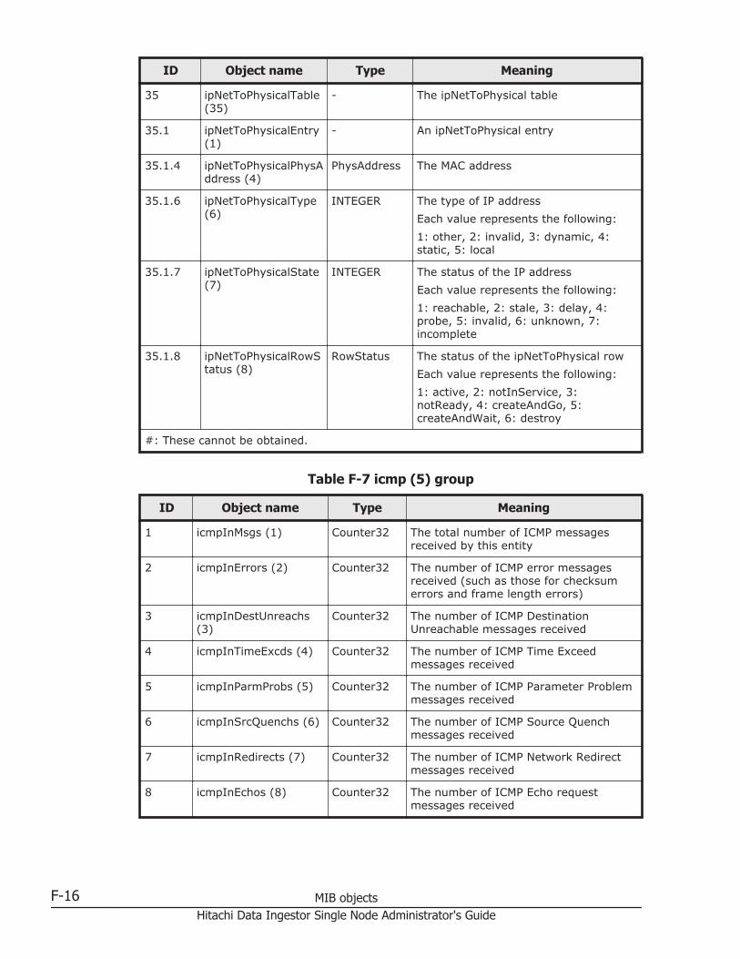
ID Object name Type Meaning
35 ipNetToPhysicalTable(35)
- The ipNetToPhysical table
35.1 ipNetToPhysicalEntry(1)
- An ipNetToPhysical entry
35.1.4 ipNetToPhysicalPhysAddress (4)
PhysAddress The MAC address
35.1.6 ipNetToPhysicalType(6)
INTEGER The type of IP address
Each value represents the following:
1: other, 2: invalid, 3: dynamic, 4:static, 5: local
35.1.7 ipNetToPhysicalState(7)
INTEGER The status of the IP address
Each value represents the following:
1: reachable, 2: stale, 3: delay, 4:probe, 5: invalid, 6: unknown, 7:incomplete
35.1.8 ipNetToPhysicalRowStatus (8)
RowStatus The status of the ipNetToPhysical row
Each value represents the following:
1: active, 2: notInService, 3:notReady, 4: createAndGo, 5:createAndWait, 6: destroy
#: These cannot be obtained.
Table F-7 icmp (5) group
ID Object name Type Meaning
1 icmpInMsgs (1) Counter32 The total number of ICMP messagesreceived by this entity
2 icmpInErrors (2) Counter32 The number of ICMP error messagesreceived (such as those for checksumerrors and frame length errors)
3 icmpInDestUnreachs(3)
Counter32 The number of ICMP DestinationUnreachable messages received
4 icmpInTimeExcds (4) Counter32 The number of ICMP Time Exceedmessages received
5 icmpInParmProbs (5) Counter32 The number of ICMP Parameter Problemmessages received
6 icmpInSrcQuenchs (6) Counter32 The number of ICMP Source Quenchmessages received
7 icmpInRedirects (7) Counter32 The number of ICMP Network Redirectmessages received
8 icmpInEchos (8) Counter32 The number of ICMP Echo requestmessages received
F-16 MIB objectsHitachi Data Ingestor Single Node Administrator's Guide

ID Object name Type Meaning
9 icmpInEchoReps (9) Counter32 The number of ICMP Echo responsemessages received
10 icmpInTimestamps(10)
Counter32 The number of ICMP TimeStamp requestmessages received
11 icmpInTimestampReps(11)
Counter32 The number of ICMP TimeStampresponse messages received
12 icmpInAddrMasks (12) Counter32 The number of ICMP Address Maskrequest messages received
13 icmpInAddrMaskReps(13)
Counter32 The number of incoming ICMP AddressMask response messages
14 icmpOutMsgs (14) Counter32 The total number of ICMP send attempts(including those for which errorsoccurred)
15 icmpOutErrors (15) Counter32 The number of ICMP messages thatwere not sent because of an error
16 icmpOutDestUnreachs(16)
Counter32 The number of ICMP DestinationUnreachable messages sent
17 icmpOutTimeExcds(17)
Counter32 The number of ICMP Time Exceededmessages sent
18 icmpOutParmProbs(18)
Counter32 The number of ICMP Parameter Problemmessages sent
19 icmpOutSrcQuenchs(19)
Counter32 The number of ICMP Source Quenchmessages sent
20 icmpOutRedirects (20) Counter32 The number of ICMP Redirect messagessent
21 icmpOutEchos (21) Counter32 The number of ICMP Echo requestmessages sent
22 icmpOutEchoReps (22) Counter32 The number of ICMP Echo responsemessages sent
23 icmpOutTimestamps(23)
Counter32 The number of ICMP Timestamp requestmessages sent
24 icmpOutTimestampReps (24)
Counter32 The number of ICMP Timestampresponse messages sent
25 icmpOutAddrMasks(25)
Counter32 The number of ICMP Address Maskrequest messages sent
26 icmpOutAddrMaskReps(26)
Counter32 The number of ICMP Address Maskresponse messages sent
Table F-8 tcp (6) group
ID Object name Type Meaning
1 tcpRtoAlgorithm (1) INTEGER The algorithm to decide the timeout timeused for retransmission
MIB objects F-17Hitachi Data Ingestor Single Node Administrator's Guide
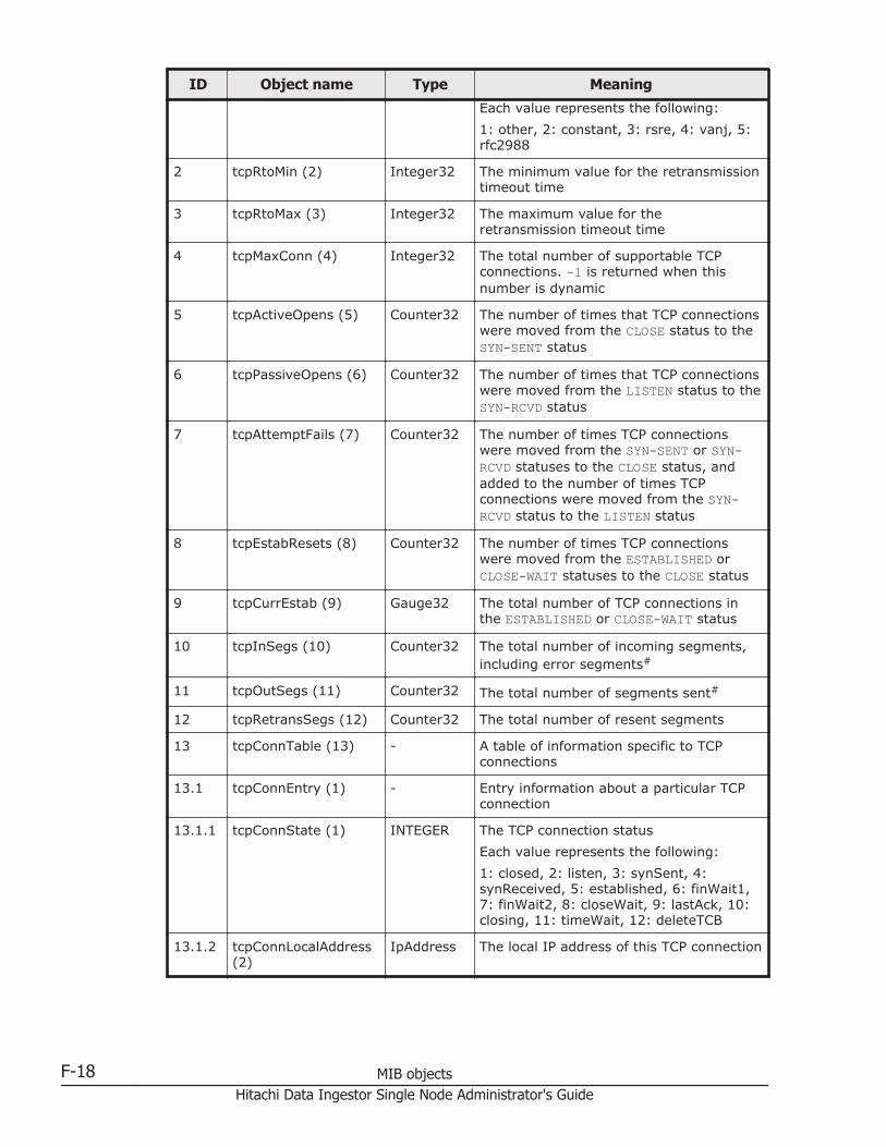
ID Object name Type Meaning
Each value represents the following:
1: other, 2: constant, 3: rsre, 4: vanj, 5:rfc2988
2 tcpRtoMin (2) Integer32 The minimum value for the retransmissiontimeout time
3 tcpRtoMax (3) Integer32 The maximum value for theretransmission timeout time
4 tcpMaxConn (4) Integer32 The total number of supportable TCPconnections. -1 is returned when thisnumber is dynamic
5 tcpActiveOpens (5) Counter32 The number of times that TCP connectionswere moved from the CLOSE status to theSYN-SENT status
6 tcpPassiveOpens (6) Counter32 The number of times that TCP connectionswere moved from the LISTEN status to theSYN-RCVD status
7 tcpAttemptFails (7) Counter32 The number of times TCP connectionswere moved from the SYN-SENT or SYN-RCVD statuses to the CLOSE status, andadded to the number of times TCPconnections were moved from the SYN-RCVD status to the LISTEN status
8 tcpEstabResets (8) Counter32 The number of times TCP connectionswere moved from the ESTABLISHED orCLOSE-WAIT statuses to the CLOSE status
9 tcpCurrEstab (9) Gauge32 The total number of TCP connections inthe ESTABLISHED or CLOSE-WAIT status
10 tcpInSegs (10) Counter32 The total number of incoming segments,including error segments#
11 tcpOutSegs (11) Counter32 The total number of segments sent#
12 tcpRetransSegs (12) Counter32 The total number of resent segments
13 tcpConnTable (13) - A table of information specific to TCPconnections
13.1 tcpConnEntry (1) - Entry information about a particular TCPconnection
13.1.1 tcpConnState (1) INTEGER The TCP connection status
Each value represents the following:
1: closed, 2: listen, 3: synSent, 4:synReceived, 5: established, 6: finWait1,7: finWait2, 8: closeWait, 9: lastAck, 10:closing, 11: timeWait, 12: deleteTCB
13.1.2 tcpConnLocalAddress(2)
IpAddress The local IP address of this TCP connection
F-18 MIB objectsHitachi Data Ingestor Single Node Administrator's Guide

ID Object name Type Meaning
13.1.3 tcpConnLocalPort (3) Integer32 The local port number of this TCPconnection
13.1.4 tcpConnRemAddress(4)
IpAddress The remote IP address of this TCPconnection
13.1.5 tcpConnRemPort (5) Integer32 The remote port number of this TCPconnection
14 tcpInErrs (14) Counter32 The total number of error segmentsreceived
15 tcpOutRsts (15) Counter32 The number of segments sent that havethe RST flag
19 tcpConnectionTable(19)
- The TCP connection table
19.1 tcpConnectionEntry(1)
- A TCP connection entry
19.1.7 tcpConnectionState(7)
INTEGER The state of the TCP connection for the IPaddress
Each value represents the following:
1: closed, 2: listen, 3: synSent, 4:synReceived, 5: established, 6: finWait1,7: finWait2, 8: closeWait, 9: lastAck, 10:closing, 11: timeWait, 12: deleteTCB
19.1.8 tcpConnectionProcess(8)
Unsigned32 The process ID for the process connectedto the network
#: ifInUcastPkts and ifOutUcastPkts are 32-bit counters, and might be reset if thesystem is continuously run for a long time.
Table F-9 udp (7) group
ID Object name Type Meaning
1 udpInDatagrams(1)
Counter32 The number of UDP datagrams reported tothe upper layer
2 udpNoPorts (2) Counter32 The total number of incoming UDP packetsfor which no parent application exists in theaddress port
3 udpInErrors (3) Counter32 The number of UDP datagrams unable to bereported to the application because ofreasons other than udpNoPorts
4 udpOutDatagrams(4)
Counter32 The total number of UDP datagrams sent bythe parent application
5 udpTable (5) - A table for UDP listener information
5.1 udpEntry (1) - The number of entries for a particular UDPlistener
5.1.1 udpLocalAddress(1)
IpAddress The local IP address of this UDP listener
MIB objects F-19Hitachi Data Ingestor Single Node Administrator's Guide
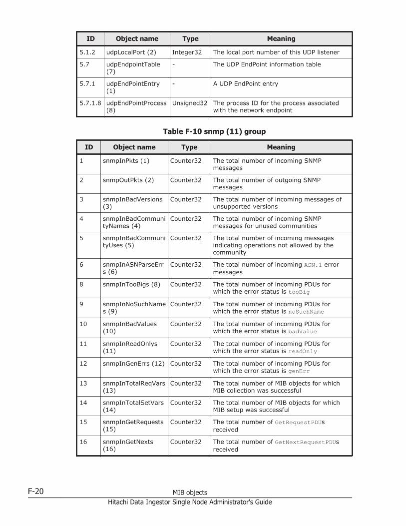
ID Object name Type Meaning
5.1.2 udpLocalPort (2) Integer32 The local port number of this UDP listener
5.7 udpEndpointTable(7)
- The UDP EndPoint information table
5.7.1 udpEndPointEntry(1)
- A UDP EndPoint entry
5.7.1.8 udpEndPointProcess(8)
Unsigned32 The process ID for the process associatedwith the network endpoint
Table F-10 snmp (11) group
ID Object name Type Meaning
1 snmpInPkts (1) Counter32 The total number of incoming SNMPmessages
2 snmpOutPkts (2) Counter32 The total number of outgoing SNMPmessages
3 snmpInBadVersions(3)
Counter32 The total number of incoming messages ofunsupported versions
4 snmpInBadCommunityNames (4)
Counter32 The total number of incoming SNMPmessages for unused communities
5 snmpInBadCommunityUses (5)
Counter32 The total number of incoming messagesindicating operations not allowed by thecommunity
6 snmpInASNParseErrs (6)
Counter32 The total number of incoming ASN.1 errormessages
8 snmpInTooBigs (8) Counter32 The total number of incoming PDUs forwhich the error status is tooBig
9 snmpInNoSuchNames (9)
Counter32 The total number of incoming PDUs forwhich the error status is noSuchName
10 snmpInBadValues(10)
Counter32 The total number of incoming PDUs forwhich the error status is badValue
11 snmpInReadOnlys(11)
Counter32 The total number of incoming PDUs forwhich the error status is readOnly
12 snmpInGenErrs (12) Counter32 The total number of incoming PDUs forwhich the error status is genErr
13 snmpInTotalReqVars(13)
Counter32 The total number of MIB objects for whichMIB collection was successful
14 snmpInTotalSetVars(14)
Counter32 The total number of MIB objects for whichMIB setup was successful
15 snmpInGetRequests(15)
Counter32 The total number of GetRequestPDUsreceived
16 snmpInGetNexts(16)
Counter32 The total number of GetNextRequestPDUsreceived
F-20 MIB objectsHitachi Data Ingestor Single Node Administrator's Guide
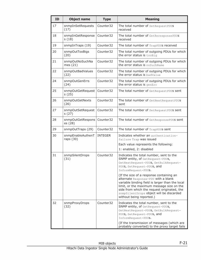
ID Object name Type Meaning
17 snmpInSetRequests(17)
Counter32 The total number of SetRequestPDUsreceived
18 snmpInGetResponses (18)
Counter32 The total number of GetReresponsePDUsreceived
19 snmpInTraps (19) Counter32 The total number of TrapPDUs received
20 snmpOutTooBigs(20)
Counter32 The total number of outgoing PDUs for whichthe error status is tooBig
21 snmpOutNoSuchNames (21)
Counter32 The total number of outgoing PDUs for whichthe error status is noSuchName
22 snmpOutBadValues(22)
Counter32 The total number of outgoing PDUs for whichthe error status is badValue
24 snmpOutGenErrs(24)
Counter32 The total number of outgoing PDUs for whichthe error status is genErr
25 snmpOutGetRequests (25)
Counter32 The total number of GetRequestPDUs sent
26 snmpOutGetNexts(26)
Counter32 The total number of GetNextRequestPDUssent
27 snmpOutSetRequests (27)
Counter32 The total number of SetRequestPDUs sent
28 snmpOutGetResponses (28)
Counter32 The total number of GetResponsePDUs sent
29 snmpOutTraps (29) Counter32 The total number of TrapPDUs sent
30 snmpEnableAuthenTraps (30)
INTEGER Indicates whether an authentication-failure Trap was issued
Each value represents the following:
1: enabled, 2: disabled
31 snmpSilentDrops(31)
Counter32 Indicates the total number, sent to theSNMP entity, of GetRequest-PDUs,GetNextRequest-PDUs, GetBulkRequest-PDUs, SetRequest-PDUs, andInformRequest-PDUs.
(If the size of a response containing analternate Response-PDU with a blankvariable binding field is larger than the locallimit, or the maximum message size on theside from which the request originated, thesnmpSilentDrops object will be discardedwithout being reported.)
32 snmpProxyDrops(32)
Counter32 Indicates the total number, sent to theSNMP entity, of GetRequest-PDUs,GetNextRequest-PDUs, GetBulkRequest-PDUs, SetRequest-PDUs, andInformRequest-PDUs.
(If the transmission of messages (which areprobably converted) to the proxy target fails
MIB objects F-21Hitachi Data Ingestor Single Node Administrator's Guide

ID Object name Type Meaning
without a Response-PDU being returned(aside from timeouts), the snmpProxyDropsobject will be discarded without beingreported.)
Note: These MIB information items are reset when SNMP agents are restarted. BecauseSNMP agents are restarted in an HDI system once a day, information for only one day isstored at most.
Table F-11 host (25) group
ID Object name Type Meaning
1 hrSystem (1) - Host resource system
1.1 hrSystemUptime (1) TimeTicks Time elapsed since system initialization
1.2 hrSystemDate (2) DateAndTime Current date and time
1.3 hrSystemInitialLoadDevice (3)
Integer32 The index of the hrDeviceEntry for thedevice from which this host is configuredto load its initial operating systemconfiguration
1.4 hrSystemInitialLoadParameters (4)
InternationalDisplayString
Parameter passed to the kernel afterLinux startup
1.5 hrSystemNumUsers(5)
Gauge32 Number of user sessions for which thishost is storing state information
1.6 hrSystemProcesses(6)
Gauge32 Number of processes currently loaded
1.7 hrSystemMaxProcesses (7)
Gauge32 Returns the fixed value 0
2 hrStorage (2) - System storage area for the host resource
2.1 hrStorageTypes (1) - Storage area type for the host resource
Note: An OID definition is used as theresponse for hrStorageType, and thisobject has no real state. The same is trueof objects from OID 2.1.1 to 2.1.10.
2.1.1 hrStorageOther (1) - The storage area type for thecorresponding index duringhrStorageType collection is not OID2.1.2to 2.1.10
2.1.2 hrStorageRam (2) - The storage area type for thecorresponding index duringhrStorageType collection corresponds toRAM
2.1.3 hrStorageVirtualMemory (3)
- The storage area type for thecorresponding index duringhrStorageType collection corresponds tovirtual memory
F-22 MIB objectsHitachi Data Ingestor Single Node Administrator's Guide

ID Object name Type Meaning
2.1.4 hrStorageFixedDisk(4)
- The storage area type for thecorresponding index duringhrStorageType collection corresponds tothe hard disk
2.1.5 hrStorageRemovableDisk (5)
- The storage area type for thecorresponding index duringhrStorageType collection corresponds tothe removable disk
2.1.6 hrStorageFloppyDisk(6)
- The storage area type for thecorresponding index duringhrStorageType collection corresponds tothe floppy disk
2.1.7 hrStorageCompactDisc (7)
- The storage area type for thecorresponding index duringhrStorageType collection corresponds tothe compact disc
2.1.8 hrStorageRamDisk(8)
- The storage area type for thecorresponding index duringhrStorageType collection corresponds tothe RAM disk
2.1.9 hrStorageFlashMemory (9)
- The storage area type for thecorresponding index duringhrStorageType collection corresponds tothe flash memory
2.1.10 hrStorageNetworkDisk (10)
- The storage area type for thecorresponding index duringhrStorageType collection corresponds toa file system in the network
2.2 hrMemorySize (2) KBytes Amount of main physical memory
2.3 hrStorageTable (3) - The (conceptual) table of logical storagearea on the host
2.3.1 hrStorageEntry (1) - The (conceptual) entry in the logicalstorage area on the host
2.3.1.1 hrStorageIndex (1) Integer32 Unique value for each logical storage areafor the host
2.3.1.2 hrStorageType (2) AutonomousType
Storage device type (OID allocated tohrStorageTypes by the index) indicatedby this entry
2.3.1.3 hrStorageDescr (3) DisplayString Name of the logical storage area
2.3.1.4 hrStorageAllocationUnits (4)
Integer32 Block size allocated from the logicalstorage area
2.3.1.5 hrStorageSize (5) Integer32 Block amount
2.3.1.6 hrStorageUsed (6) Integer32 Block usage
3 hrDevice (3) - Device
3.1 hrDeviceTypes (1) - Device type
MIB objects F-23Hitachi Data Ingestor Single Node Administrator's Guide

ID Object name Type Meaning
Note: An OID definition is used as theresponse for hrDeviceType, and thisobject has no real state. The same is trueof objects from OID3.1.1 to 3.1.6, or3.1.10 to 3.1.21.
3.1.1 hrDeviceOther (1) - The device type for the correspondingindex during hrDeviceType collection isnot OID 3.1.2 to 3.1.6, or 3.1.10 to3.1.21
3.1.2 hrDeviceUnknown(2)
- The device type for the correspondingindex during hrDeviceType collectioncannot be recognized
3.1.3 hrDeviceProcessor(3)
- The device type for the correspondingindex during hrDeviceType collectioncorresponds to the processor (CPU)
3.1.4 hrDeviceNetwork (4) - The device type for the correspondingindex during hrDeviceType collectioncorresponds to the network interface
3.1.5 hrDevicePrinter (5) - The device type for the correspondingindex during hrDeviceType collectioncorresponds to the printer
3.1.6 hrDeviceDiskStorage(6)
- The device type for the correspondingindex during hrDeviceType collectioncorresponds to the disk
3.1.10 hrDeviceVideo (10) - The device type for the correspondingindex during hrDeviceType collectioncorresponds to the video device
3.1.11 hrDeviceAudio (11) - The device type for the correspondingindex during hrDeviceType collectioncorresponds to the audio device
3.1.12 hrDeviceCoprocessor(12)
- The device type for the correspondingindex during hrDeviceType collectioncorresponds to the coprocessor
3.1.13 hrDeviceKeyboard(13)
- The device type for the correspondingindex during hrDeviceType collectioncorresponds to the keyboard
3.1.14 hrDeviceModem (14) - The device type for the correspondingindex during hrDeviceType collectioncorresponds to the modem
3.1.15 hrDeviceParallelPort(15)
- The device type for the correspondingindex during hrDeviceType collectioncorresponds to the parallel port
3.1.16 hrDevicePointing(16)
- The device type for the correspondingindex during hrDeviceType collectioncorresponds to a pointing device such as amouse
F-24 MIB objectsHitachi Data Ingestor Single Node Administrator's Guide

ID Object name Type Meaning
3.1.17 hrDeviceSerialPort(17)
- The device type for the correspondingindex during hrDeviceType collectioncorresponds to the serial port
3.1.18 hrDeviceTape (18) - The device type for the correspondingindex during hrDeviceType collectioncorresponds to the tape device
3.1.19 hrDeviceClock (19) - The device type for the correspondingindex during hrDeviceType collectioncorresponds to the clock
3.1.20 hrDeviceVolatileMemory (20)
- The device type for the correspondingindex during hrDeviceType collectioncorresponds to volatile memory
3.1.21 hrDeviceNonVolatileMemory (21)
- The device type for the correspondingindex during hrDeviceType collectioncorresponds to non-volatile memory
3.2 hrDeviceTable (2) - The (conceptual) table for the devices onthe host
3.2.1 hrDeviceEntry (1) - The (conceptual) entry for a device on thehost
3.2.1.1 hrDeviceIndex (1) Integer32 Unique value for each device on the host
3.2.1.2 hrDeviceType (2) AutonomousType
The device type indicated by this entry(OID allocated to hrDeviceTypes by theindex)
3.2.1.3 hrDeviceDescr (3) DisplayString Device name
3.2.1.4 hrDeviceID (4) ProductID Device ID
3.3 hrProcessorTable (3) - The (conceptual) table for the processorson the host
3.3.1 hrProcessorEntry (1) - The (conceptual) entry for a processor onthe host
3.3.1.1 hrProcessorFrwID(1)
ProductID Processor firmware ID
3.4 hrNetworkTable (4) - The (conceptual) table for the networkdevices on the host
3.4.1 hrNetworkEntry (1) - The (conceptual) entry for a networkdevice on the host
3.4.1.1 hrNetworkIfIndex(1)
InterfaceIndexOrZero
Value of ifIndex corresponding to thisnetwork device
3.6 hrDiskStorageTable(6)
- The (conceptual) table for long-termstorage devices on the host
3.6.1 hrDiskStorageEntry(1)
- The (conceptual) entry for a long-termstorage device on the host
3.6.1.1 hrDiskStorageAccess(1)
INTEGER Access attribute
Each value represents the following:
MIB objects F-25Hitachi Data Ingestor Single Node Administrator's Guide
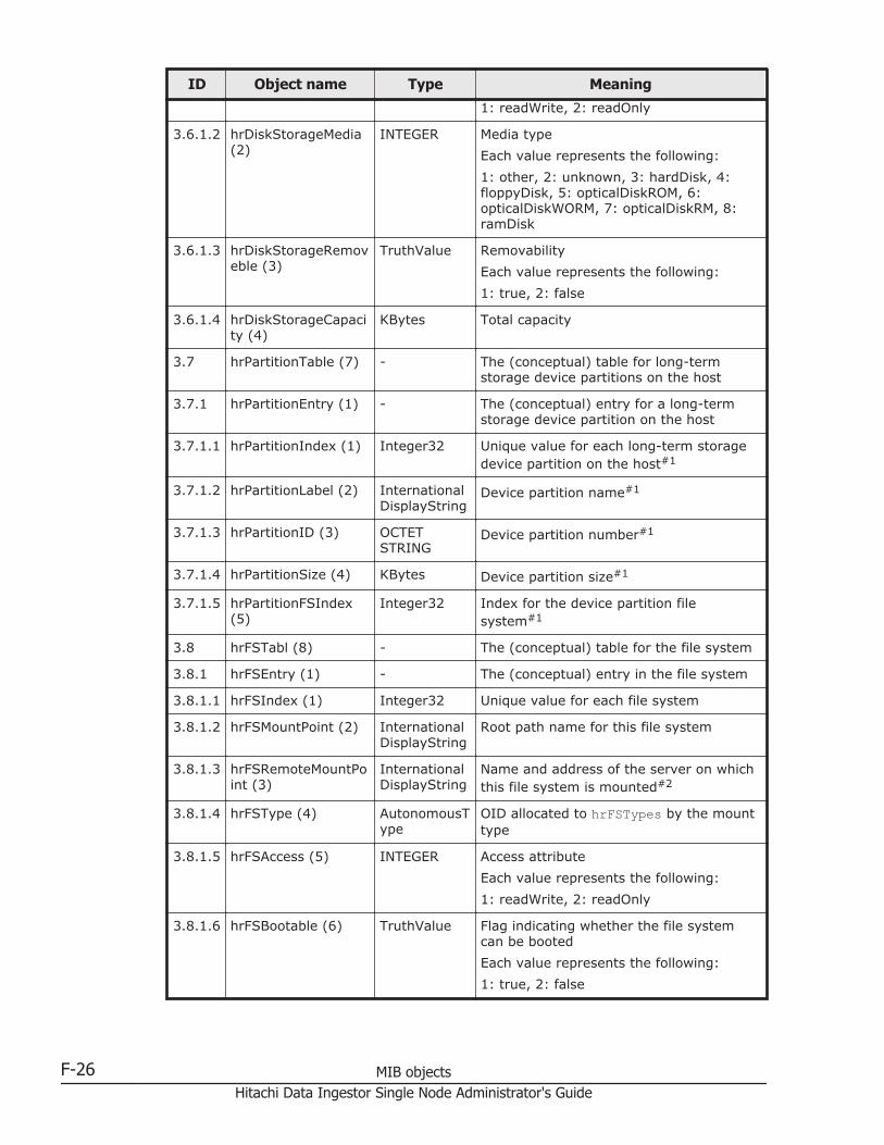
ID Object name Type Meaning
1: readWrite, 2: readOnly
3.6.1.2 hrDiskStorageMedia(2)
INTEGER Media type
Each value represents the following:
1: other, 2: unknown, 3: hardDisk, 4:floppyDisk, 5: opticalDiskROM, 6:opticalDiskWORM, 7: opticalDiskRM, 8:ramDisk
3.6.1.3 hrDiskStorageRemoveble (3)
TruthValue Removability
Each value represents the following:
1: true, 2: false
3.6.1.4 hrDiskStorageCapacity (4)
KBytes Total capacity
3.7 hrPartitionTable (7) - The (conceptual) table for long-termstorage device partitions on the host
3.7.1 hrPartitionEntry (1) - The (conceptual) entry for a long-termstorage device partition on the host
3.7.1.1 hrPartitionIndex (1) Integer32 Unique value for each long-term storagedevice partition on the host#1
3.7.1.2 hrPartitionLabel (2) InternationalDisplayString
Device partition name#1
3.7.1.3 hrPartitionID (3) OCTETSTRING
Device partition number#1
3.7.1.4 hrPartitionSize (4) KBytes Device partition size#1
3.7.1.5 hrPartitionFSIndex(5)
Integer32 Index for the device partition filesystem#1
3.8 hrFSTabl (8) - The (conceptual) table for the file system
3.8.1 hrFSEntry (1) - The (conceptual) entry in the file system
3.8.1.1 hrFSIndex (1) Integer32 Unique value for each file system
3.8.1.2 hrFSMountPoint (2) InternationalDisplayString
Root path name for this file system
3.8.1.3 hrFSRemoteMountPoint (3)
InternationalDisplayString
Name and address of the server on whichthis file system is mounted#2
3.8.1.4 hrFSType (4) AutonomousType
OID allocated to hrFSTypes by the mounttype
3.8.1.5 hrFSAccess (5) INTEGER Access attribute
Each value represents the following:
1: readWrite, 2: readOnly
3.8.1.6 hrFSBootable (6) TruthValue Flag indicating whether the file systemcan be booted
Each value represents the following:
1: true, 2: false
F-26 MIB objectsHitachi Data Ingestor Single Node Administrator's Guide

ID Object name Type Meaning
3.8.1.7 hrFSStorageIndex(7)
Integer32 Index to hrStorageEntry indicatinginformation about this file system
3.8.1.8 hrFSLastFullBackupDate (8)
DateAndTime Last date on which this file system wascopied to another storage device forbackup#3
3.8.1.9 hrFSLastPartialBackupDate (9)
DateAndTime Last date on which part of this file systemwas copied to another storage device forbackup#3
3.9 hrFSTypes (9) - Device type
Note: An OID definition is used as theresponse for hrFSType, and this objecthas no real state. The same is true ofobject OID3.9.1.
3.9.1 hrFSOther (1) - Only XFS can be used as the file systemfor this system. Because there are noobjects corresponding to XFS inhrFSTypes (8), this object is allocated.
5 hrSWRunPerf (5) - Performance table for running software
5.1 hrSWRunPerfTable(1)
- The (conceptual) table for performancemetrics of running software
5.1.1 hrSWRunPerfEntry(1)
- The (conceptual) entry for performancemetrics of running software
5.1.1.1 hrSWRunPerfCPU (1) Integer32 CPU time spent running a process (units:10ms)
5.1.1.2 hrSWRunPerfMem(2)
KBytes Total actual system memory allocated torunning processes
#1: These cannot be obtained.
#2: Null ("") is always obtained.
#3: The value of 0-1-1,0:0:0.0 is always obtained.
Table F-12 ifMIB (31) group
ID Object name Type Meaning
1 ifMIBObjects (1) - The additional object for interfaceentries
1.1 ifXTable (1) - A list of interface entries. The numberof entries is given by the value ofifNumber. This table containsadditional objects for the interfacetable
1.1.1 ifXEntry (1) - An entry containing additionalmanagement information applicable toa particular interface
1.1.1.1 ifName (1) DisplayString The textual name of the interface
MIB objects F-27Hitachi Data Ingestor Single Node Administrator's Guide
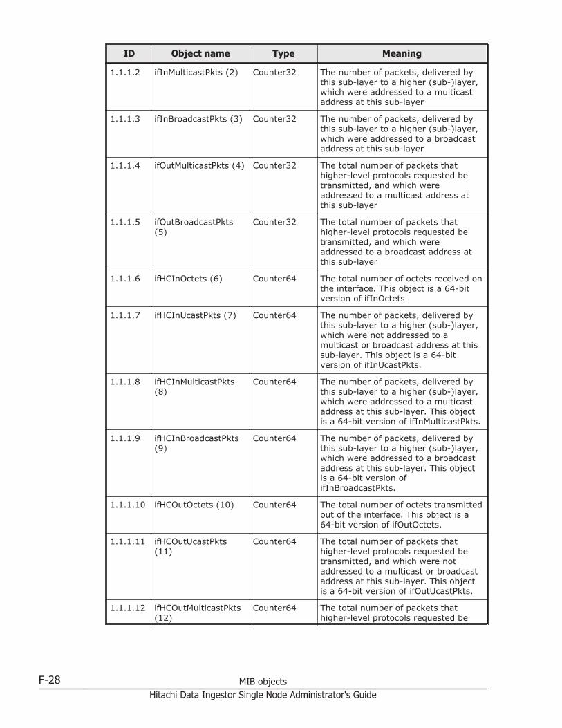
ID Object name Type Meaning
1.1.1.2 ifInMulticastPkts (2) Counter32 The number of packets, delivered bythis sub-layer to a higher (sub-)layer,which were addressed to a multicastaddress at this sub-layer
1.1.1.3 ifInBroadcastPkts (3) Counter32 The number of packets, delivered bythis sub-layer to a higher (sub-)layer,which were addressed to a broadcastaddress at this sub-layer
1.1.1.4 ifOutMulticastPkts (4) Counter32 The total number of packets thathigher-level protocols requested betransmitted, and which wereaddressed to a multicast address atthis sub-layer
1.1.1.5 ifOutBroadcastPkts(5)
Counter32 The total number of packets thathigher-level protocols requested betransmitted, and which wereaddressed to a broadcast address atthis sub-layer
1.1.1.6 ifHCInOctets (6) Counter64 The total number of octets received onthe interface. This object is a 64-bitversion of ifInOctets
1.1.1.7 ifHCInUcastPkts (7) Counter64 The number of packets, delivered bythis sub-layer to a higher (sub-)layer,which were not addressed to amulticast or broadcast address at thissub-layer. This object is a 64-bitversion of ifInUcastPkts.
1.1.1.8 ifHCInMulticastPkts(8)
Counter64 The number of packets, delivered bythis sub-layer to a higher (sub-)layer,which were addressed to a multicastaddress at this sub-layer. This objectis a 64-bit version of ifInMulticastPkts.
1.1.1.9 ifHCInBroadcastPkts(9)
Counter64 The number of packets, delivered bythis sub-layer to a higher (sub-)layer,which were addressed to a broadcastaddress at this sub-layer. This objectis a 64-bit version ofifInBroadcastPkts.
1.1.1.10 ifHCOutOctets (10) Counter64 The total number of octets transmittedout of the interface. This object is a64-bit version of ifOutOctets.
1.1.1.11 ifHCOutUcastPkts(11)
Counter64 The total number of packets thathigher-level protocols requested betransmitted, and which were notaddressed to a multicast or broadcastaddress at this sub-layer. This objectis a 64-bit version of ifOutUcastPkts.
1.1.1.12 ifHCOutMulticastPkts(12)
Counter64 The total number of packets thathigher-level protocols requested be
F-28 MIB objectsHitachi Data Ingestor Single Node Administrator's Guide
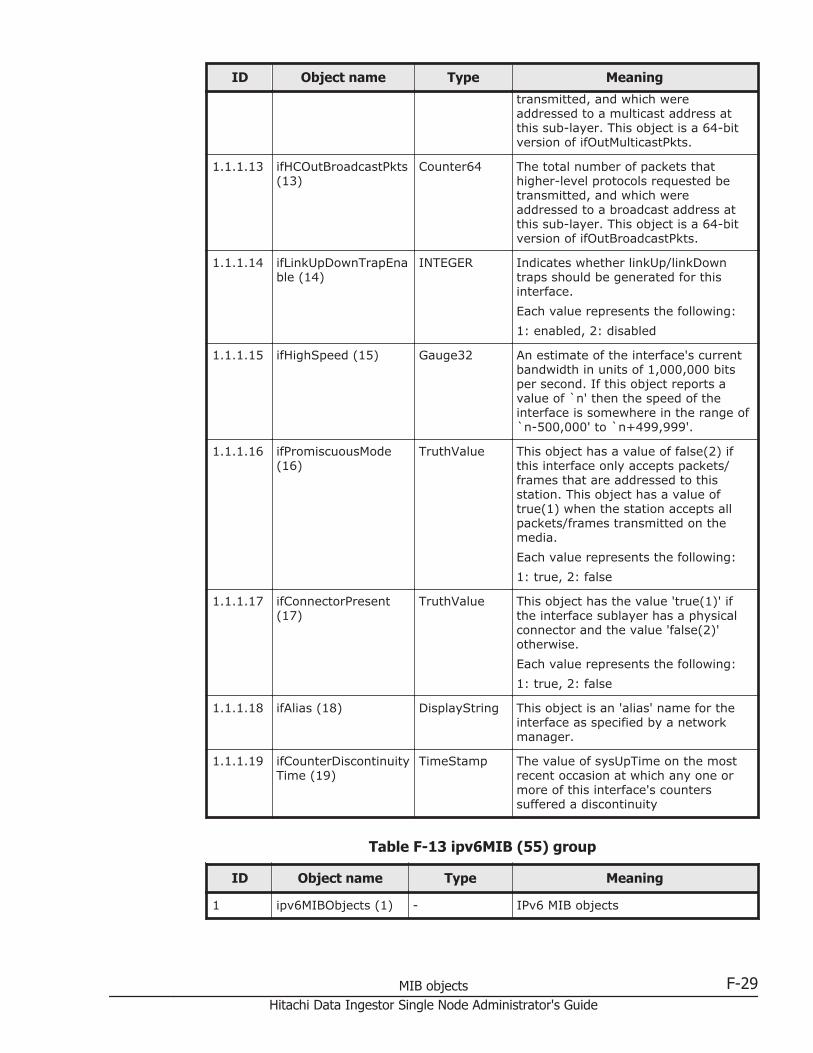
ID Object name Type Meaning
transmitted, and which wereaddressed to a multicast address atthis sub-layer. This object is a 64-bitversion of ifOutMulticastPkts.
1.1.1.13 ifHCOutBroadcastPkts(13)
Counter64 The total number of packets thathigher-level protocols requested betransmitted, and which wereaddressed to a broadcast address atthis sub-layer. This object is a 64-bitversion of ifOutBroadcastPkts.
1.1.1.14 ifLinkUpDownTrapEnable (14)
INTEGER Indicates whether linkUp/linkDowntraps should be generated for thisinterface.
Each value represents the following:
1: enabled, 2: disabled
1.1.1.15 ifHighSpeed (15) Gauge32 An estimate of the interface's currentbandwidth in units of 1,000,000 bitsper second. If this object reports avalue of `n' then the speed of theinterface is somewhere in the range of`n-500,000' to `n+499,999'.
1.1.1.16 ifPromiscuousMode(16)
TruthValue This object has a value of false(2) ifthis interface only accepts packets/frames that are addressed to thisstation. This object has a value oftrue(1) when the station accepts allpackets/frames transmitted on themedia.
Each value represents the following:
1: true, 2: false
1.1.1.17 ifConnectorPresent(17)
TruthValue This object has the value 'true(1)' ifthe interface sublayer has a physicalconnector and the value 'false(2)'otherwise.
Each value represents the following:
1: true, 2: false
1.1.1.18 ifAlias (18) DisplayString This object is an 'alias' name for theinterface as specified by a networkmanager.
1.1.1.19 ifCounterDiscontinuityTime (19)
TimeStamp The value of sysUpTime on the mostrecent occasion at which any one ormore of this interface's counterssuffered a discontinuity
Table F-13 ipv6MIB (55) group
ID Object name Type Meaning
1 ipv6MIBObjects (1) - IPv6 MIB objects
MIB objects F-29Hitachi Data Ingestor Single Node Administrator's Guide
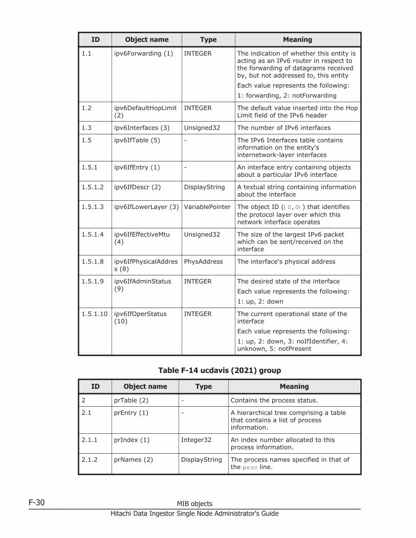
ID Object name Type Meaning
1.1 ipv6Forwarding (1) INTEGER The indication of whether this entity isacting as an IPv6 router in respect tothe forwarding of datagrams receivedby, but not addressed to, this entity
Each value represents the following:
1: forwarding, 2: notForwarding
1.2 ipv6DefaultHopLimit(2)
INTEGER The default value inserted into the HopLimit field of the IPv6 header
1.3 ipv6Interfaces (3) Unsigned32 The number of IPv6 interfaces
1.5 ipv6IfTable (5) - The IPv6 Interfaces table containsinformation on the entity'sinternetwork-layer interfaces
1.5.1 ipv6IfEntry (1) - An interface entry containing objectsabout a particular IPv6 interface
1.5.1.2 ipv6IfDescr (2) DisplayString A textual string containing informationabout the interface
1.5.1.3 ipv6IfLowerLayer (3) VariablePointer The object ID ({0,0}) that identifiesthe protocol layer over which thisnetwork interface operates
1.5.1.4 ipv6IfEffectiveMtu(4)
Unsigned32 The size of the largest IPv6 packetwhich can be sent/received on theinterface
1.5.1.8 ipv6IfPhysicalAddress (8)
PhysAddress The interface's physical address
1.5.1.9 ipv6IfAdminStatus(9)
INTEGER The desired state of the interface
Each value represents the following:
1: up, 2: down
1.5.1.10 ipv6IfOperStatus(10)
INTEGER The current operational state of theinterface
Each value represents the following:
1: up, 2: down, 3: noIfIdentifier, 4:unknown, 5: notPresent
Table F-14 ucdavis (2021) group
ID Object name Type Meaning
2 prTable (2) - Contains the process status.
2.1 prEntry (1) - A hierarchical tree comprising a tablethat contains a list of processinformation.
2.1.1 prIndex (1) Integer32 An index number allocated to thisprocess information.
2.1.2 prNames (2) DisplayString The process names specified in that ofthe proc line.
F-30 MIB objectsHitachi Data Ingestor Single Node Administrator's Guide
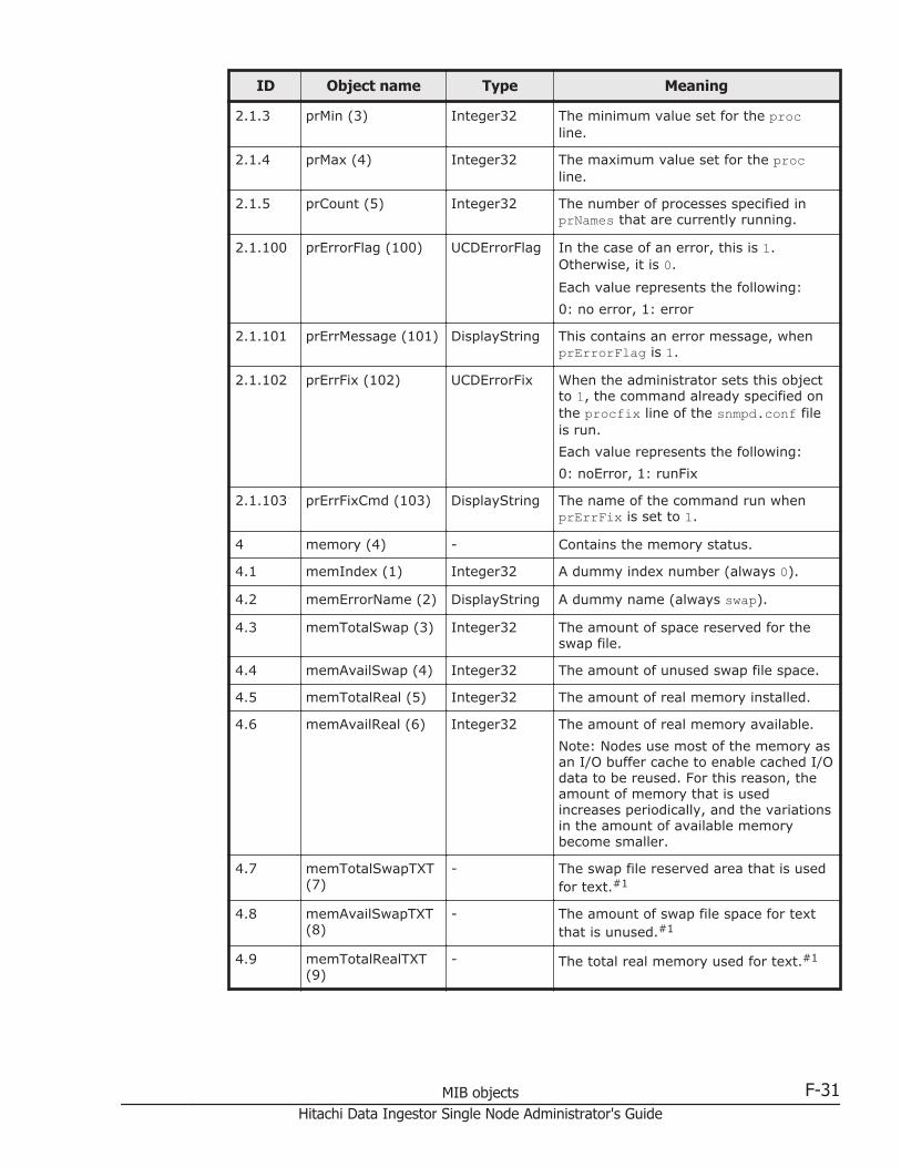
ID Object name Type Meaning
2.1.3 prMin (3) Integer32 The minimum value set for the procline.
2.1.4 prMax (4) Integer32 The maximum value set for the procline.
2.1.5 prCount (5) Integer32 The number of processes specified inprNames that are currently running.
2.1.100 prErrorFlag (100) UCDErrorFlag In the case of an error, this is 1.Otherwise, it is 0.
Each value represents the following:
0: no error, 1: error
2.1.101 prErrMessage (101) DisplayString This contains an error message, whenprErrorFlag is 1.
2.1.102 prErrFix (102) UCDErrorFix When the administrator sets this objectto 1, the command already specified onthe procfix line of the snmpd.conf fileis run.
Each value represents the following:
0: noError, 1: runFix
2.1.103 prErrFixCmd (103) DisplayString The name of the command run whenprErrFix is set to 1.
4 memory (4) - Contains the memory status.
4.1 memIndex (1) Integer32 A dummy index number (always 0).
4.2 memErrorName (2) DisplayString A dummy name (always swap).
4.3 memTotalSwap (3) Integer32 The amount of space reserved for theswap file.
4.4 memAvailSwap (4) Integer32 The amount of unused swap file space.
4.5 memTotalReal (5) Integer32 The amount of real memory installed.
4.6 memAvailReal (6) Integer32 The amount of real memory available.
Note: Nodes use most of the memory asan I/O buffer cache to enable cached I/Odata to be reused. For this reason, theamount of memory that is usedincreases periodically, and the variationsin the amount of available memorybecome smaller.
4.7 memTotalSwapTXT(7)
- The swap file reserved area that is usedfor text.#1
4.8 memAvailSwapTXT(8)
- The amount of swap file space for textthat is unused.#1
4.9 memTotalRealTXT(9)
- The total real memory used for text.#1
MIB objects F-31Hitachi Data Ingestor Single Node Administrator's Guide

ID Object name Type Meaning
4.10 memAvailRealTXT(10)
- The amount of available memory usedfor text.#1
4.11 memTotalFree (11) Integer32 The total available memory.
4.12 memMinimumSwap(12)
Integer32 The available size of the swap file duringan error.
4.13 memShared (13) Integer32 The total amount of shared memory.
4.14 memBuffer (14) Integer32 The total amount of buffer memory.
4.15 memCached (15) Integer32 The total amount of cache memory.
4.100 memSwapError(100)
UCDErrorFlag The swap error flag.
Each value represents the following:
0: noError, 1: runFix
4.101 memSwapErrorMsg(101)
DisplayString The error message when memSwapErroris 1.
8 extTable (8) - Runs the commands already specified onthe system, and contains the results.
8.1 extEntry (1) - A hierarchical tree that holds a tablecontaining data from execution results.
8.1.1 extIndex (1) Integer32 An index number.
8.1.2 extNames (2) DisplayString The name specified for the set name inthe exec line.
8.1.3 extCommand (3) DisplayString The full path name and arguments of theexecution file specified in the exec line.
8.1.100 extResult (100) DisplayString The error code returned when theexecution file specified in extCommand isrun.
8.1.101 extOutput (101) DisplayString The execution results of the executionfile specified in extCommand.
8.1.102 extErrFix (102) UCDErrorFix When the administrator sets this objectto 1, the command already specified inthe execfix line of the snmpd.conf fileis run.
Each value represents the following:
0: noError, 1: runFix
8.1.103 extErrFixCmd (103) DisplayString The name of the command run whenextErrFix is set to 1.
9 dskTable (9) - Contains the disk status.
9.1 dskEntry (1) - A hierarchical tree to hold diskinformation.
9.1.1 dskIndex (1) Integer32 An index number.
9.1.2 dskPath (2) DisplayString The path name of the inspection target.
F-32 MIB objectsHitachi Data Ingestor Single Node Administrator's Guide

ID Object name Type Meaning
The value specified for the path name tobe inspected, in the disk line.
9.1.3 dskDevice (3) DisplayString The device name contained in dskPath.
9.1.4 dskMinimum (4) Integer32 The minimum amount for error handlingspecified in the disk line (-1 when apercentage is specified).
9.1.5 dskMinPercent (5) Integer32 The minimum percentage amount forerror handling specified in the disk line(-1 when units are specified in KB).
9.1.6 dskTotal (6) Integer32 The maximum amount that can bestored on the device specified indskDevice.
9.1.7 dskAvail (7) Integer32 The amount of space currently availableon the device specified in dskDevice.
9.1.8 dskUsed (8) Integer32 The current usage rate of the devicespecified in dskDevice.
9.1.9 dskPercent (9) Integer32 The current usage rate of the devicespecified in dskDevice, expressed as apercentage.
9.1.10 dskPercentNode(10)
Integer32 The current inode usage rate of thedevice specified in dskDevice, expressedas a percentage.
9.1.11 dskTotalLow (11) Unsigned32 Total size of the disk/partition (KB).Together with dskTotalHigh composes64-bit number.#2 (That is, the twodskTotalHigh and dskTotalLow valuesrequire a total of 64 bits.)
9.1.12 dskTotalHigh (12) Unsigned32 Total size of the disk/partition (KB).Together with dskTotalLow composes64-bit number.#2 (That is, the twodskTotalHigh and dskTotalLow valuesrequire a total of 64 bits.)
9.1.13 dskAvailLow (13) Unsigned32 Unused capacity on the disk (KB).Together with dskAvailHigh composes64-bit number.#2 (That is, the twodskAvailHigh and dskAvailLow valuesrequire a total of 64 bits.)
9.1.14 dskAvailHigh (14) Unsigned32 Unused capacity on the disk (KB).Together with dskAvailLow composes64-bit number.#2 (That is, the twodskAvailHigh and dskAvailLow valuesrequire a total of 64 bits.)
9.1.15 dskUsedLow (15) Unsigned32 Used capacity on the disk (KB). Togetherwith dskUsedHigh composes 64-bitnumber.#2 (That is, the twodskUsedHigh and dskUsedLow valuesrequire a total of 64 bits.)
MIB objects F-33Hitachi Data Ingestor Single Node Administrator's Guide
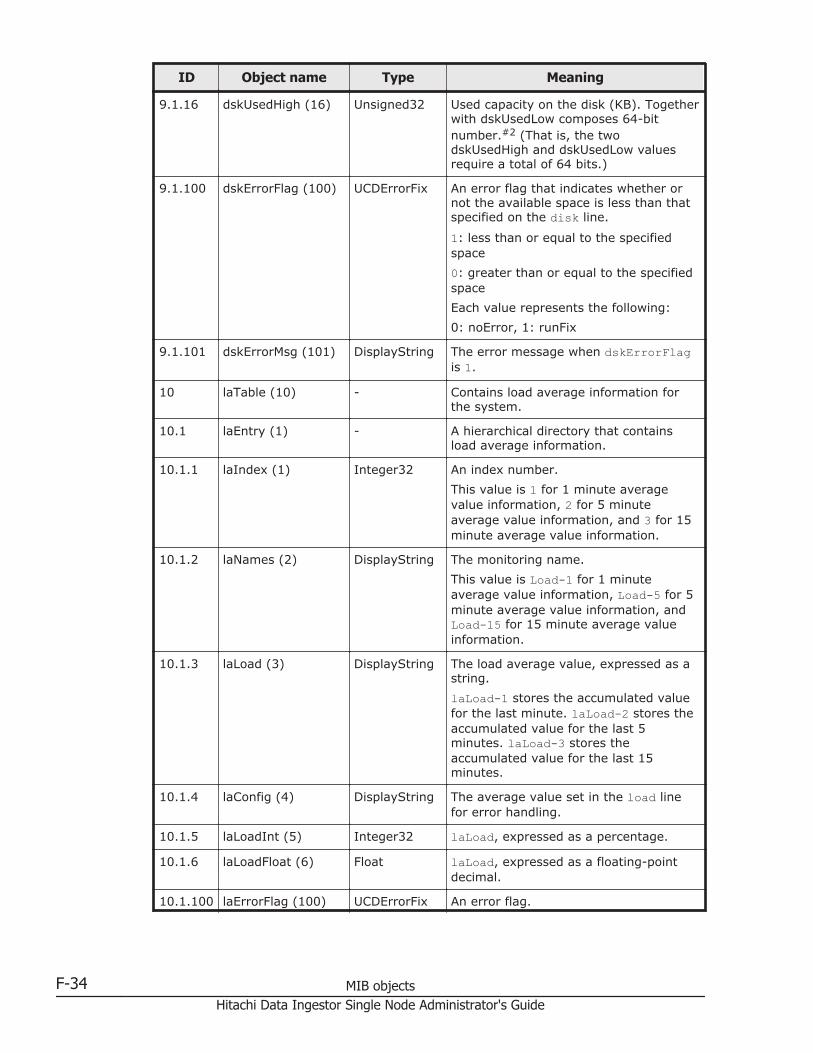
ID Object name Type Meaning
9.1.16 dskUsedHigh (16) Unsigned32 Used capacity on the disk (KB). Togetherwith dskUsedLow composes 64-bitnumber.#2 (That is, the twodskUsedHigh and dskUsedLow valuesrequire a total of 64 bits.)
9.1.100 dskErrorFlag (100) UCDErrorFix An error flag that indicates whether ornot the available space is less than thatspecified on the disk line.
1: less than or equal to the specifiedspace
0: greater than or equal to the specifiedspace
Each value represents the following:
0: noError, 1: runFix
9.1.101 dskErrorMsg (101) DisplayString The error message when dskErrorFlagis 1.
10 laTable (10) - Contains load average information forthe system.
10.1 laEntry (1) - A hierarchical directory that containsload average information.
10.1.1 laIndex (1) Integer32 An index number.
This value is 1 for 1 minute averagevalue information, 2 for 5 minuteaverage value information, and 3 for 15minute average value information.
10.1.2 laNames (2) DisplayString The monitoring name.
This value is Load-1 for 1 minuteaverage value information, Load-5 for 5minute average value information, andLoad-15 for 15 minute average valueinformation.
10.1.3 laLoad (3) DisplayString The load average value, expressed as astring.
laLoad-1 stores the accumulated valuefor the last minute. laLoad-2 stores theaccumulated value for the last 5minutes. laLoad-3 stores theaccumulated value for the last 15minutes.
10.1.4 laConfig (4) DisplayString The average value set in the load linefor error handling.
10.1.5 laLoadInt (5) Integer32 laLoad, expressed as a percentage.
10.1.6 laLoadFloat (6) Float laLoad, expressed as a floating-pointdecimal.
10.1.100 laErrorFlag (100) UCDErrorFix An error flag.
F-34 MIB objectsHitachi Data Ingestor Single Node Administrator's Guide

ID Object name Type Meaning
This value is 1 when the set averagevalue of the load average is exceeded,and 0 otherwise.
Each value represents the following:
0: noError, 1: runFix
10.1.101 laErrMessage (101) DisplayString The error message whenlaLoadErrorFlag is 1.
11 systemStats (11) - Contains the system status.
11.1 ssIndex (1) Integer32 A dummy index number (always 1).
11.2 ssErrorName (2) DisplayString The systemStats name (alwayssystemStats).
11.3 ssSwapIn (3) Integer32 The time required for swap-in.
11.4 ssSwapOut (4) Integer32 The time required for swap-out.
11.5 ssIOSent (5) Integer32 The time required for transmission to theblock device.
11.6 ssIOReceive (6) Integer32 The time required for reception from theblock device.
11.7 ssSysInterrupts (7) Integer32 The number of interruptions for 1second, including clock interruptions.
11.8 ssSysContext (8) Integer32 The number of context switchesswitched for 1 second.
11.9 ssCpuUser (9) Integer32 The ratio of CPU capacity used by theuser.
11.10 ssCpuSystem (10) Integer32 The ratio of CPU capacity used by thesystem.
11.11 ssCpuIdle (11) Integer32 The ratio of CPU capacity that is idle.
11.50 ssCpuRawUser (50) Counter32 The time for which the user is using theCPU.
11.51 ssCpuRawNice (51) Counter32 The value of the nice process.
11.52 ssCpuRawSystem(52)
Counter32 The time for which the user is using theCPU.
11.53 ssCpuRawIdle (53) Counter32 The time for which the CPU is idle.
11.54 ssCpuRawWait (54) Counter32 CPU time spent waiting for I/O
11.55 ssCpuRawKernel(55)
Counter32 Kernel CPU time
11.56 ssCpuRawInterrupt(56)
Counter32 Interrupt level CPU time
11.57 ssIORawSent (57) Counter32 Number of requests sent to blockdevices
11.58 ssIORawReceived(58)
Counter32 Number of requests received from blockdevices
MIB objects F-35Hitachi Data Ingestor Single Node Administrator's Guide

ID Object name Type Meaning
11.59 ssRawInterrupts(59)
Counter32 Number of interrupts
11.60 ssRawContexts (60) Counter32 Number of context switches
11.61 ssCpuRawSoftIRQ(61)
Counter32 Time for performing soft interruptprocessing
11.62 ssRawSwapIn (62) Counter32 Number of blocks swapped in
11.63 ssRawSwapOut (63) Counter32 Number of blocks swapped out
13 ucdExperimental(13)
- An experimental MIB
13.14 ucdDlmodMIB (14) - The dynamic load module MIB.
The function for loading a predefinedMIB definition file during snmpdoperation.
13.14.1 dlmodNextIndex (1) Integer32 The index of the next-loaded MIB.
13.15 ucdDiskIOMIB (15) - This MIB module defines objects for diskI/O statistics.
13.15.1 diskIOTable (1) - Table of IO devices and how much datathey have read/written
13.15.1.1
diskIOEntry (1) - An entry containing a device and itsstatistics
13.15.1.1.1
diskIOIndex (1) Integer32 Reference index for each observeddevice
13.15.1.1.2
diskIODevice (2) DisplayString The name of the device we are counting/checking (Example: ram0, sda)
13.15.1.1.3
diskIONRead (3) Counter32 The number of bytes read from thisdevice since boot (32-bit counter)
13.15.1.1.4
diskIONWritten (4) Counter32 The number of bytes written to thisdevice since boot (32-bit counter)
13.15.1.1.5
diskIOReads (5) Counter32 The number of read accesses from thisdevice since boot
13.15.1.1.6
diskIOWrites (6) Counter32 The number of write accesses to thisdevice since boot
13.15.1.1.12
diskIONReadX (12) Counter64 The number of bytes read from thisdevice since boot (64-bit version)
13.15.1.1.13
diskIONWrittenX(13)
Counter64 The number of bytes written to thisdevice since boot (64-bit version)
16 logMatch (16) - Log search
16.1 logMatchMaxEntries(1)
Integer32 Maximum number of supportablelogMatch entries
100 version (100) - Contains the snmpd version information.
100.1 versionIndex (1) Integer32 The index to MIB.
F-36 MIB objectsHitachi Data Ingestor Single Node Administrator's Guide

ID Object name Type Meaning
100.2 versionTag (2) DisplayString The CVS tag keyword.
100.3 versionDate (3) DisplayString The date from the RCS keyword.
100.4 versionCDate (4) DisplayString The date from ctime().
100.5 versionIdent (5) DisplayString The ID from the RCS keyword.
100.6 versionConfigureOptions (6)
DisplayString If this agent is configured, options aremoved to the config script.
100.10 versionClearCache(10)
Integer32 When this is set to 1, the executioncache is cleared.
100.11 versionUpdateConfig (11)
Integer32 When this is set to 1, the config file isread.
100.12 versionRestartAgent(12)
Integer32 When this is set to 1, the agent isrestarted.
100.13 versionSavePersistentData (13)
Integer32 When this is set to 1, persistent data forthe agent is saved immediately.
100.20 versionDoDebugging (20)
Integer32 When this is set to 1, the devicestatement is released with a 0.
101 snmperrs (101) - Contains snmpd error information.
101.1 snmperrIndex (1) Integer32 A fake index for snmperrs.
101.2 snmperrNames (2) DisplayString Snmp
101.100 snmperrErrorFlag(100)
UCDErrorFlag An error flag indicating a problem withthe agent.
Each value represents the following:
0: noError, 1: error
101.101 snmperrErrMessage(101)
DisplayString A message explaining the problem.
#1: These cannot be obtained.
#2: The following is an example of how to calculate the capacity when dskTotalLow is3431333888 and dskTotalHigh is 4872:
1. Convert the obtained MIB values to hexadecimal numbers.
3431333888 = 0xCC860000
4872 = 0x1308
2. Concatenate the hexadecimal dskTotalHigh in front of dskTotalLow.
0x1308, 0xCC860000 = 0x1308CC860000
3. Convert the concatenated number to a decimal number.
0x1308CC860000 = 20928512000000 (KB)
Table F-15 netSnmp (8072) group
ID Object name Type Meaning
1 netSnmpObjects (1) - Objects for netSnmp
MIB objects F-37Hitachi Data Ingestor Single Node Administrator's Guide

ID Object name Type Meaning
1.2 nsMibRegistry (2) - Monitor for registered MIB modules
1.2.1 nsModuleTable (1) - Table displaying all OIDs registeredby the MIB module
1.2.1.1 nsModuleEntry (1) - MIB module entry
1.2.1.1.1 nsmContextName(1)
- Context name for the registered MIBmodule#
1.2.1.1.2 nsmRegistrationPoint (2)
- OID for the registered MIB module#
1.2.1.1.3 nsmRegistrationPriority (3)
- Priority for the registered MIBmodule#
1.2.1.1.4 nsModuleName (4) DisplayString Name of the registered MIB module
1.2.1.1.5 nsModuleModes (5) BITS Access attribute for the registeredMIB module
Each value represents the following:
0: getAndGetNext, 1: set, 2:getBulk
1.2.1.1.6 nsModuleTimeout(6)
Integer32 Timeout value for the registeredMIB module
1.5 nsCache (5) - Objects related to saving SNMPagent data
1.5.1 nsCacheDefaultTimeout (1)
INTEGER Initial save timeout value
1.5.2 nsCacheEnabled (2) TruthValue Whether save is enabled
Each value represents the following:
1: true, 2: false
1.5.3 nsCacheTable (3) - Table for each MIB module andsaved data
1.5.3.1 nsCacheEntry (1) - Conceptual entry in the save table
1.5.3.1.1 nsCachedOID (1) - OID for saved data#
1.5.3.1.2 nsCacheTimeout (2) INTEGER Entry-specific save timeout value
1.5.3.1.3 nsCacheStatus (3) NetsnmpCacheStatus
Current status of entry-specific save
Each value represents the following:
1: enabled, 2: disabled, 3: empty,4: active, 5: empty
1.7 nsConfiguration (7) - Group for debugging and loggingsettings
1.7.1 nsConfigDebug (1) - Debugging settings (this is active ifthe debugging option is specifiedwhen snmpd is started)
1.7.1.1 nsDebugEnabled (1) TruthValue Setting used to output debugginginformation
F-38 MIB objectsHitachi Data Ingestor Single Node Administrator's Guide
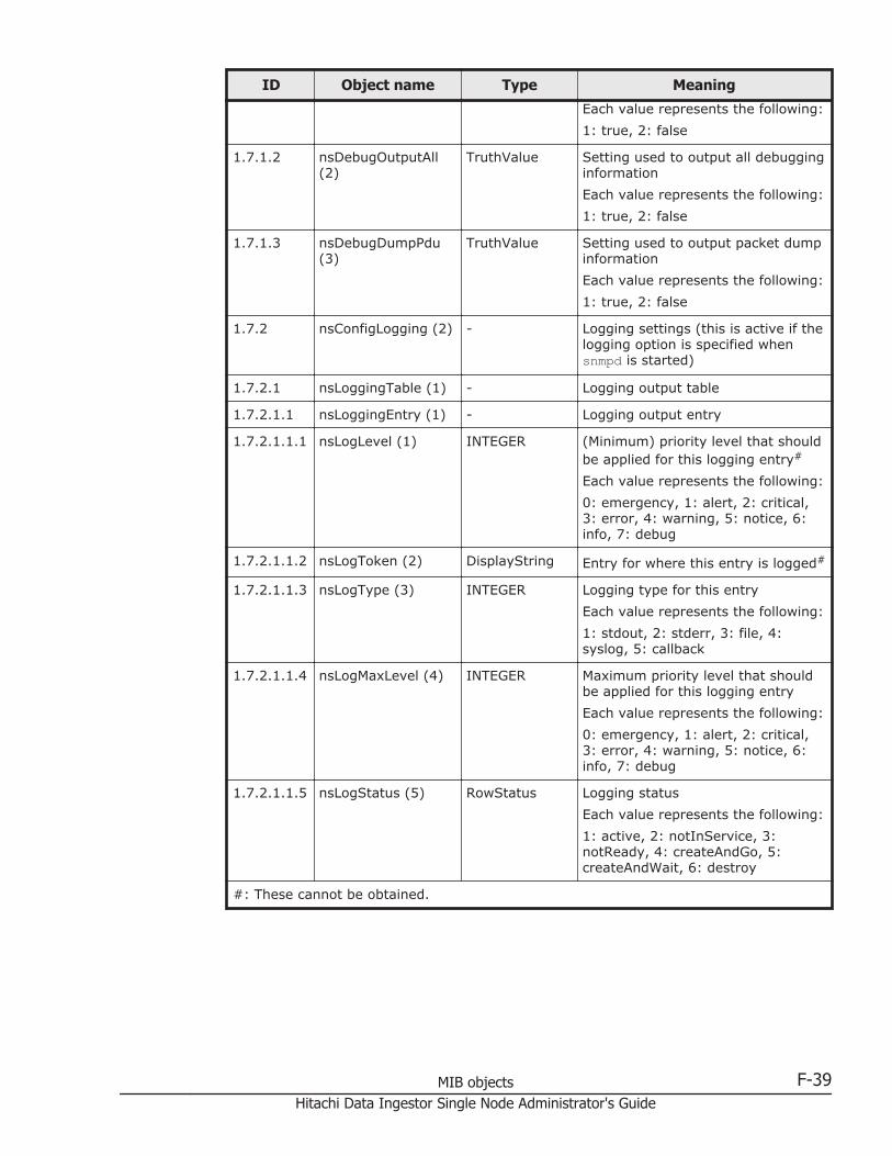
ID Object name Type Meaning
Each value represents the following:
1: true, 2: false
1.7.1.2 nsDebugOutputAll(2)
TruthValue Setting used to output all debugginginformation
Each value represents the following:
1: true, 2: false
1.7.1.3 nsDebugDumpPdu(3)
TruthValue Setting used to output packet dumpinformation
Each value represents the following:
1: true, 2: false
1.7.2 nsConfigLogging (2) - Logging settings (this is active if thelogging option is specified whensnmpd is started)
1.7.2.1 nsLoggingTable (1) - Logging output table
1.7.2.1.1 nsLoggingEntry (1) - Logging output entry
1.7.2.1.1.1 nsLogLevel (1) INTEGER (Minimum) priority level that shouldbe applied for this logging entry#
Each value represents the following:
0: emergency, 1: alert, 2: critical,3: error, 4: warning, 5: notice, 6:info, 7: debug
1.7.2.1.1.2 nsLogToken (2) DisplayString Entry for where this entry is logged#
1.7.2.1.1.3 nsLogType (3) INTEGER Logging type for this entry
Each value represents the following:
1: stdout, 2: stderr, 3: file, 4:syslog, 5: callback
1.7.2.1.1.4 nsLogMaxLevel (4) INTEGER Maximum priority level that shouldbe applied for this logging entry
Each value represents the following:
0: emergency, 1: alert, 2: critical,3: error, 4: warning, 5: notice, 6:info, 7: debug
1.7.2.1.1.5 nsLogStatus (5) RowStatus Logging status
Each value represents the following:
1: active, 2: notInService, 3:notReady, 4: createAndGo, 5:createAndWait, 6: destroy
#: These cannot be obtained.
MIB objects F-39Hitachi Data Ingestor Single Node Administrator's Guide
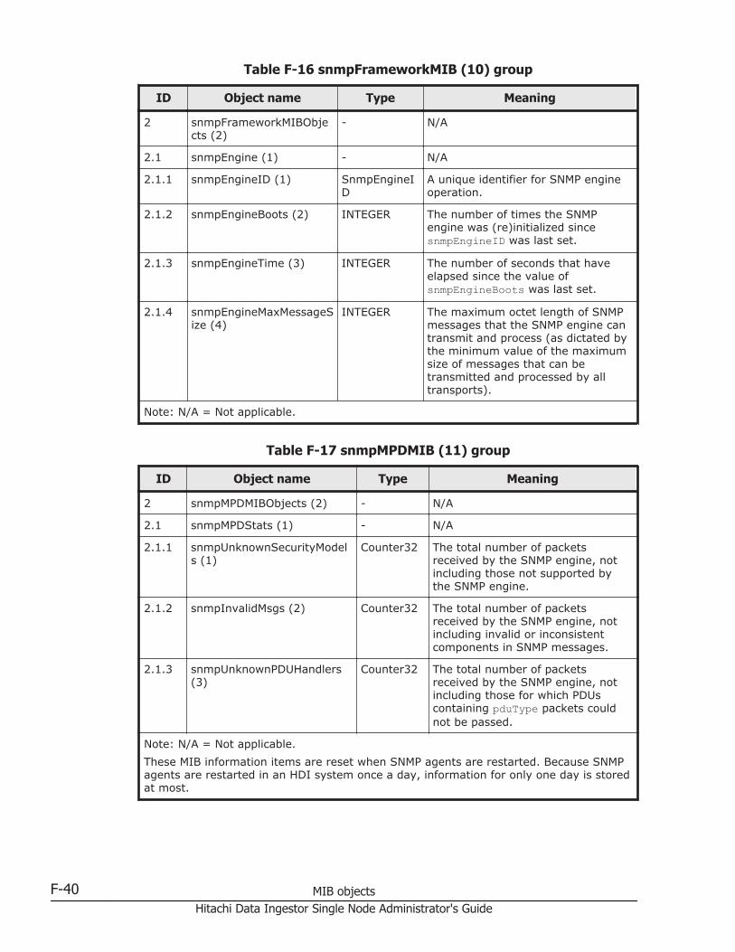
Table F-16 snmpFrameworkMIB (10) group
ID Object name Type Meaning
2 snmpFrameworkMIBObjects (2)
- N/A
2.1 snmpEngine (1) - N/A
2.1.1 snmpEngineID (1) SnmpEngineID
A unique identifier for SNMP engineoperation.
2.1.2 snmpEngineBoots (2) INTEGER The number of times the SNMPengine was (re)initialized sincesnmpEngineID was last set.
2.1.3 snmpEngineTime (3) INTEGER The number of seconds that haveelapsed since the value ofsnmpEngineBoots was last set.
2.1.4 snmpEngineMaxMessageSize (4)
INTEGER The maximum octet length of SNMPmessages that the SNMP engine cantransmit and process (as dictated bythe minimum value of the maximumsize of messages that can betransmitted and processed by alltransports).
Note: N/A = Not applicable.
Table F-17 snmpMPDMIB (11) group
ID Object name Type Meaning
2 snmpMPDMIBObjects (2) - N/A
2.1 snmpMPDStats (1) - N/A
2.1.1 snmpUnknownSecurityModels (1)
Counter32 The total number of packetsreceived by the SNMP engine, notincluding those not supported bythe SNMP engine.
2.1.2 snmpInvalidMsgs (2) Counter32 The total number of packetsreceived by the SNMP engine, notincluding invalid or inconsistentcomponents in SNMP messages.
2.1.3 snmpUnknownPDUHandlers(3)
Counter32 The total number of packetsreceived by the SNMP engine, notincluding those for which PDUscontaining pduType packets couldnot be passed.
Note: N/A = Not applicable.
These MIB information items are reset when SNMP agents are restarted. Because SNMPagents are restarted in an HDI system once a day, information for only one day is storedat most.
F-40 MIB objectsHitachi Data Ingestor Single Node Administrator's Guide

Table F-18 snmpTargetMIB (12) group
ID Object name Type Meaning
1 snmpTargetObjects (1) - N/A
1.2 snmpTargetAddrTable(2)
- The transport table is used to createSNMP messages.
1.2.1 snmpTargetAddrEntry(1)
- The transport address is used tocreate SNMP operations.
1.2.1.1 snmpTargetAddrName(1)
SnmpAdminString
A unique identifier that is locallyoptional but related to thissnmpTargetAddrEntry.#
1.2.1.2 snmpTargetAddrTDomain (2)
TDomain Indicates the address of the transporttype included in thesnmpTargetAddrTAddress object.
1.2.1.3 snmpTargetAddrTAddress (3)
TAddress This address format, which containsthe transport address, is dependenton the value of thesnmpTargetAddrTDomain object.
1.2.1.4 snmpTargetAddrTimeout (4)
TimeInterval This reflects the expected maximumround-trip time for contacting thetransport address defined in this row.
1.2.1.5 snmpTargetAddrRetryCount (5)
Integer32 Specifies the default number ofretries when a message, for which aresponse was created, cannot bereceived.
1.2.1.6 snmpTargetAddrTagList(6)
SnmpTagList Contains the tag list used to choosethe target address for a particularoperation.
1.2.1.7 snmpTargetAddrParams(7)
SnmpAdminString
Identifies an entry from within thesnmpTargetParamsTable.
1.2.1.8 snmpTargetAddrStorageType (8)
StorageType The memory type.
Each value represents the following:
1: other, 2: volatile, 3: nonvolatile,4: permanent, 5: readOnly
1.2.1.9 snmpTargetAddrRowStatus (9)
RowStatus The status.
Each value represents the following:
1: active, 2: notInService, 3:notReady, 4: createAndGo, 5:createAndWait, 6: destroy
1.3 snmpTargetParamsTable (3)
- A table of SNMP target informationused to create SNMP messages.
1.3.1 snmpTargetParamsEntry (1)
- One piece of information for oneSNMP set.
1.3.1.1 snmpTargetParamsName (1)
SnmpAdminString
A unique identifier that is locallyoptional but related to thissnmpTargetParamsEntry.#
MIB objects F-41Hitachi Data Ingestor Single Node Administrator's Guide
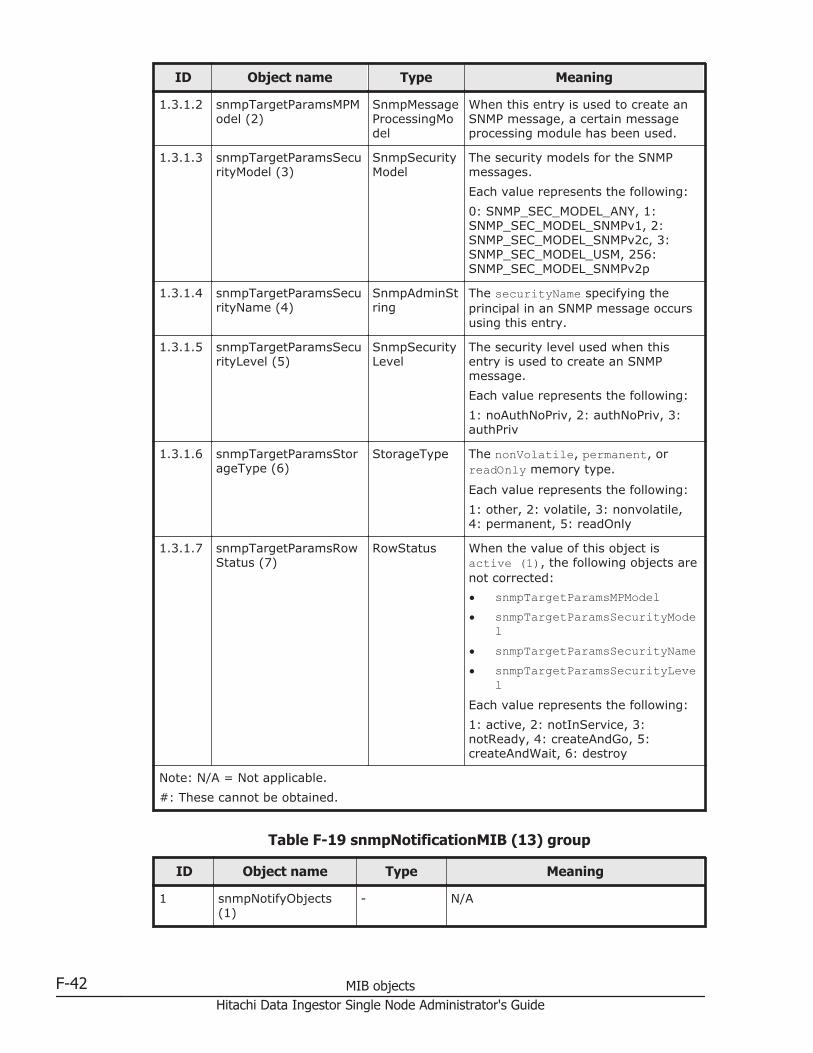
ID Object name Type Meaning
1.3.1.2 snmpTargetParamsMPModel (2)
SnmpMessageProcessingModel
When this entry is used to create anSNMP message, a certain messageprocessing module has been used.
1.3.1.3 snmpTargetParamsSecurityModel (3)
SnmpSecurityModel
The security models for the SNMPmessages.
Each value represents the following:
0: SNMP_SEC_MODEL_ANY, 1:SNMP_SEC_MODEL_SNMPv1, 2:SNMP_SEC_MODEL_SNMPv2c, 3:SNMP_SEC_MODEL_USM, 256:SNMP_SEC_MODEL_SNMPv2p
1.3.1.4 snmpTargetParamsSecurityName (4)
SnmpAdminString
The securityName specifying theprincipal in an SNMP message occursusing this entry.
1.3.1.5 snmpTargetParamsSecurityLevel (5)
SnmpSecurityLevel
The security level used when thisentry is used to create an SNMPmessage.
Each value represents the following:
1: noAuthNoPriv, 2: authNoPriv, 3:authPriv
1.3.1.6 snmpTargetParamsStorageType (6)
StorageType The nonVolatile, permanent, orreadOnly memory type.
Each value represents the following:
1: other, 2: volatile, 3: nonvolatile,4: permanent, 5: readOnly
1.3.1.7 snmpTargetParamsRowStatus (7)
RowStatus When the value of this object isactive (1), the following objects arenot corrected:
• snmpTargetParamsMPModel• snmpTargetParamsSecurityMode
l• snmpTargetParamsSecurityName• snmpTargetParamsSecurityLeve
lEach value represents the following:
1: active, 2: notInService, 3:notReady, 4: createAndGo, 5:createAndWait, 6: destroy
Note: N/A = Not applicable.
#: These cannot be obtained.
Table F-19 snmpNotificationMIB (13) group
ID Object name Type Meaning
1 snmpNotifyObjects(1)
- N/A
F-42 MIB objectsHitachi Data Ingestor Single Node Administrator's Guide
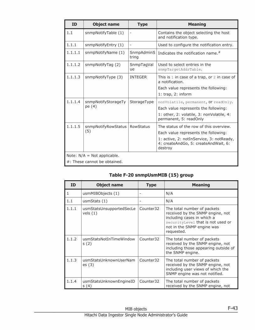
ID Object name Type Meaning
1.1 snmpNotifyTable (1) - Contains the object selecting the hostand notification type.
1.1.1 snmpNotifyEntry (1) - Used to configure the notification entry.
1.1.1.1 snmpNotifyName (1) SnmpAdminString
Indicates the notification name.#
1.1.1.2 snmpNotifyTag (2) SnmpTagValue
Used to select entries in thesnmpTargetAddrTable.
1.1.1.3 snmpNotifyType (3) INTEGER This is 1 in case of a trap, or 2 in case ofa notification.
Each value represents the following:
1: trap, 2: inform
1.1.1.4 snmpNotifyStorageType (4)
StorageType nonVolatile, permanent, or readOnly.
Each value represents the following:
1: other, 2: volatile, 3: nonVolatile, 4:permanent, 5: readOnly
1.1.1.5 snmpNotifyRowStatus(5)
RowStatus The status of the row of this overview.
Each value represents the following:
1: active, 2: notInService, 3: notReady,4: createAndGo, 5: createAndWait, 6:destroy
Note: N/A = Not applicable.
#: These cannot be obtained.
Table F-20 snmpUsmMIB (15) group
ID Object name Type Meaning
1 usmMIBObjects (1) - N/A
1.1 usmStats (1) - N/A
1.1.1 usmStatsUnsupportedSecLevels (1)
Counter32 The total number of packetsreceived by the SNMP engine, notincluding cases in which asecurityLevel that is not used ornot in the SNMP engine wasrequested.
1.1.2 usmStatsNotInTimeWindows (2)
Counter32 The total number of packetsreceived by the SNMP engine, notincluding those appearing outside ofthe SNMP engine.
1.1.3 usmStatsUnknownUserNames (3)
Counter32 The total number of packetsreceived by the SNMP engine, notincluding user views of which theSNMP engine was not notified.
1.1.4 usmStatsUnknownEngineIDs (4)
Counter32 The total number of packetsreceived by the SNMP engine, not
MIB objects F-43Hitachi Data Ingestor Single Node Administrator's Guide
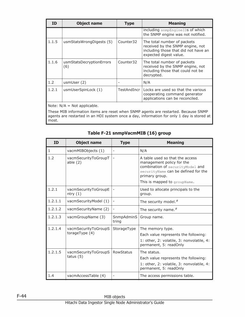
ID Object name Type Meaning
including snmpEngineIDs of whichthe SNMP engine was not notified.
1.1.5 usmStatsWrongDigests (5) Counter32 The total number of packetsreceived by the SNMP engine, notincluding those that did not have anexpected digest value.
1.1.6 usmStatsDecryptionErrors(6)
Counter32 The total number of packetsreceived by the SNMP engine, notincluding those that could not bedecrypted.
1.2 usmUser (2) - N/A
1.2.1 usmUserSpinLock (1) TestAndIncr Locks are used so that the variouscooperating command generatorapplications can be reconciled.
Note: N/A = Not applicable.
These MIB information items are reset when SNMP agents are restarted. Because SNMPagents are restarted in an HDI system once a day, information for only 1 day is stored atmost.
Table F-21 snmpVacmMIB (16) group
ID Object name Type Meaning
1 vacmMIBObjects (1) - N/A
1.2 vacmSecurityToGroupTable (2)
- A table used so that the accessmanagement policy for thecombination of securityModel andsecurityName can be defined for theprimary group.
This is mapped to groupName.
1.2.1 vacmSecurityToGroupEntry (1)
- Used to allocate principals to thegroup.
1.2.1.1 vacmSecurityModel (1) - The security model.#
1.2.1.2 vacmSecurityName (2) - The security name.#
1.2.1.3 vacmGroupName (3) SnmpAdminString
Group name.
1.2.1.4 vacmSecurityToGroupStorageType (4)
StorageType The memory type.
Each value represents the following:
1: other, 2: volatile, 3: nonvolatile, 4:permanent, 5: readOnly
1.2.1.5 vacmSecurityToGroupStatus (5)
RowStatus The status.
Each value represents the following:
1: other, 2: volatile, 3: nonvolatile, 4:permanent, 5: readOnly
1.4 vacmAccessTable (4) - The access permissions table.
F-44 MIB objectsHitachi Data Ingestor Single Node Administrator's Guide

ID Object name Type Meaning
1.4.1 vacmAccessEntry (1) - The access permissions configured inthe Local Configuration Datastore(LCD) permitting access to SNMP.
1.4.1.1 vacmAccessContextPrefix (1)
- The value of this object must matchcontextName, so that accesspermissions can be obtained.#
1.4.1.2 vacmAccessSecurityModel (2)
- This securityModel must be used toobtain access permissions.#
1.4.1.3 vacmAccessSecurityLevel (3)
- The minimum security level.#
1.4.1.4 vacmAccessContextMatch (4)
INTEGER The method by which the context forexact or prefix requests matchesvacmAccessContextPrefix.
Each value represents the following:
1: exact, 2: prefix
1.4.1.5 vacmAccessReadViewName (5)
SnmpAdminString
Used to define the view subtree forGetRequests.
1.4.1.6 vacmAccessWriteViewName (6)
SnmpAdminString
Used to define the view subtree forSetRequests.
1.4.1.7 vacmAccessNotifyViewName (7)
SnmpAdminString
Used to define the view subtree sothat objects within trap messages andInformRequests can be loaded asVarBinds.
1.4.1.8 vacmAccessStorageType (8)
StorageType The memory type.
Each value represents the following:
1: other, 2: volatile, 3: nonvolatile, 4:permanent, 5: readOnly
1.4.1.9 vacmAccessStatus (9) RowStatus The status.
Each value represents the following:
1: other, 2: volatile, 3: nonvolatile, 4:permanent, 5: readOnly
1.5 vacmMIBViews (5) - N/A
1.5.1 vacmViewSpinLock (1) TestAndIncr Locks enable set operation usage tobe adjusted when SNMP commandgenerators are used to create ormodify a view.
1.5.2 vacmViewTreeFamilyTable (2)
- Locally stored information about afamily of a subtree in MIB.
1.5.2.1 vacmViewTreeFamilyEntry (1)
- Information about a particular familyof a subtree.
1.5.2.1.1
vacmViewTreeFamilyViewName (1)
SnmpAdminString
The human-readable name of familyof the view subtree.#
MIB objects F-45Hitachi Data Ingestor Single Node Administrator's Guide

ID Object name Type Meaning
1.5.2.1.2
vacmViewTreeFamilySubtree (2)
- The MIB subtree that defines thefamily of the view subtree forvacmViewTreeFamilyMask.#
1.5.2.1.3
vacmViewTreeFamilyMask (3)
OCTETSTRING
The mask that defines the family ofthe view subtree forvacmViewTreeFamilySubtree.
1.5.2.1.4
vacmViewTreeFamilyType (4)
INTEGER Indicates whether or not the subtreeunder the OID defined invacmViewTreeFamilySubtree can beaccessed.
Each value represents the following:
1: include, 2: exclude
1.5.2.1.5
vacmViewTreeFamilyStorageType (5)
StorageType The memory type.
Each value represents the following:
1: other, 2: volatile, 3: nonvolatile, 4:permanent, 5: readOnly
1.5.2.1.6
vacmViewTreeFamilyStatus (6)
RowStatus The status.
Each value represents the following:
1: other, 2: volatile, 3: nonvolatile, 4:permanent, 5: readOnly
Note: N/A = Not applicable.
#: These cannot be obtained.
Table F-22 stdExMibQuotaTable (2) group
ID Object name Type Meaning
1 quotaEntry (1) - Quota management information foreach file system
1.1 quotaFSIndex (1) INTEGER The index number that correspondsto the file system
1.2 quotaFSMntPoint (2) DisplayString The mount point for the file system
1.3 quotaFSBlockMaxGrace(3)
INTEGER The grace period (number of days)when the number of blocks exceedsthe soft limit
1.4 quotaFSFileMaxGrace (4) INTEGER The grace period (number of days)when the number of inodes exceedsthe soft limit
1.5 quotaFSStatus (5) INTEGER Quota status (off/on)
Each value represents the following:
0: off, 1: on, 2: group-on, 3: user-on
1.6 quotaFSUserTable (6) - Information about quotamanagement for users
F-46 MIB objectsHitachi Data Ingestor Single Node Administrator's Guide
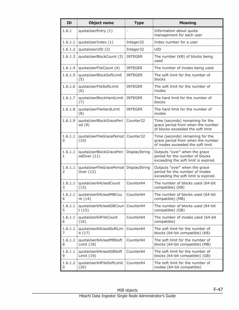
ID Object name Type Meaning
1.6.1 quotaUserEntry (1) - Information about quotamanagement for each user
1.6.1.1 quotaUserIndex (1) Integer32 Index number for a user
1.6.1.2 quotaUserUID (2) Integer32 UID
1.6.1.3 quotaUserBlockCount (3) INTEGER The number (KB) of blocks beingused
1.6.1.4 quotaUserFileCount (4) INTEGER The number of inodes being used
1.6.1.5 quotaUserBlockSoftLimit(5)
INTEGER The soft limit for the number ofblocks
1.6.1.6 quotaUserFileSoftLimit(6)
INTEGER The soft limit for the number ofinodes
1.6.1.7 quotaUserBlockHardLimit(7)
INTEGER The hard limit for the number ofblocks
1.6.1.8 quotaUserFileHardLimit(8)
INTEGER The hard limit for the number ofinodes
1.6.1.9 quotaUserBlockGracePeriod (9)
Counter32 Time (seconds) remaining for thegrace period from when the numberof blocks exceeded the soft limit
1.6.1.10
quotaUserFileGracePeriod(10)
Counter32 Time (seconds) remaining for thegrace period from when the numberof inodes exceeded the soft limit
1.6.1.11
quotaUserBlockGracePeriodOver (11)
DisplayString Outputs "over" when the graceperiod for the number of blocksexceeding the soft limit is expired.
1.6.1.12
quotaUserFileGracePeriodOver (12)
DisplayString Outputs "over" when the graceperiod for the number of inodesexceeding the soft limit is expired.
1.6.1.13
quotaUser64UsedCount(13)
Counter64 The number of blocks used (64-bitcompatible) (KB)
1.6.1.14
quotaUser64UsedMBCount (14)
Counter64 The number of blocks used (64-bitcompatible) (MB)
1.6.1.15
quotaUser64UsedGBCount (15)
Counter64 The number of blocks used (64-bitcompatible) (GB)
1.6.1.16
quotaUser64FileCount(16)
Counter64 The number of inodes used (64-bitcompatible)
1.6.1.17
quotaUser64UsedSoftLimit (17)
Counter64 The soft limit for the number ofblocks (64-bit compatible) (KB)
1.6.1.18
quotaUser64UsedMBSoftLimit (18)
Counter64 The soft limit for the number ofblocks (64-bit compatible) (MB)
1.6.1.19
quotaUser64UsedGBSoftLimit (19)
Counter64 The soft limit for the number ofblocks (64-bit compatible) (GB)
1.6.1.20
quotaUser64FileSoftLimit(20)
Counter64 The soft limit for the number ofinodes (64-bit compatible)
MIB objects F-47Hitachi Data Ingestor Single Node Administrator's Guide
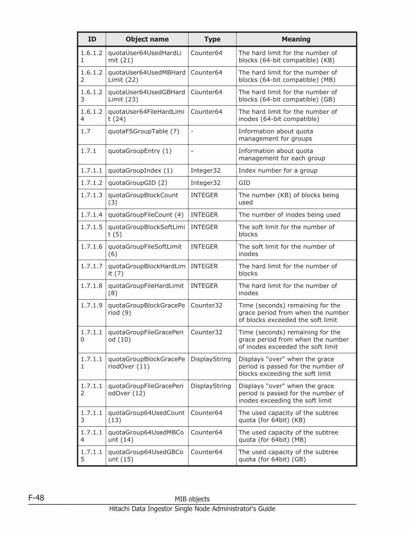
ID Object name Type Meaning
1.6.1.21
quotaUser64UsedHardLimit (21)
Counter64 The hard limit for the number ofblocks (64-bit compatible) (KB)
1.6.1.22
quotaUser64UsedMBHardLimit (22)
Counter64 The hard limit for the number ofblocks (64-bit compatible) (MB)
1.6.1.23
quotaUser64UsedGBHardLimit (23)
Counter64 The hard limit for the number ofblocks (64-bit compatible) (GB)
1.6.1.24
quotaUser64FileHardLimit (24)
Counter64 The hard limit for the number ofinodes (64-bit compatible)
1.7 quotaFSGroupTable (7) - Information about quotamanagement for groups
1.7.1 quotaGroupEntry (1) - Information about quotamanagement for each group
1.7.1.1 quotaGroupIndex (1) Integer32 Index number for a group
1.7.1.2 quotaGroupGID (2) Integer32 GID
1.7.1.3 quotaGroupBlockCount(3)
INTEGER The number (KB) of blocks beingused
1.7.1.4 quotaGroupFileCount (4) INTEGER The number of inodes being used
1.7.1.5 quotaGroupBlockSoftLimit (5)
INTEGER The soft limit for the number ofblocks
1.7.1.6 quotaGroupFileSoftLimit(6)
INTEGER The soft limit for the number ofinodes
1.7.1.7 quotaGroupBlockHardLimit (7)
INTEGER The hard limit for the number ofblocks
1.7.1.8 quotaGroupFileHardLimit(8)
INTEGER The hard limit for the number ofinodes
1.7.1.9 quotaGroupBlockGracePeriod (9)
Counter32 Time (seconds) remaining for thegrace period from when the numberof blocks exceeded the soft limit
1.7.1.10
quotaGroupFileGracePeriod (10)
Counter32 Time (seconds) remaining for thegrace period from when the numberof inodes exceeded the soft limit
1.7.1.11
quotaGroupBlockGracePeriodOver (11)
DisplayString Displays "over" when the graceperiod is passed for the number ofblocks exceeding the soft limit
1.7.1.12
quotaGroupFileGracePeriodOver (12)
DisplayString Displays "over" when the graceperiod is passed for the number ofinodes exceeding the soft limit
1.7.1.13
quotaGroup64UsedCount(13)
Counter64 The used capacity of the subtreequota (for 64bit) (KB)
1.7.1.14
quotaGroup64UsedMBCount (14)
Counter64 The used capacity of the subtreequota (for 64bit) (MB)
1.7.1.15
quotaGroup64UsedGBCount (15)
Counter64 The used capacity of the subtreequota (for 64bit) (GB)
F-48 MIB objectsHitachi Data Ingestor Single Node Administrator's Guide

ID Object name Type Meaning
1.7.1.16
quotaGroup64FileCount(16)
Counter64 The number of inodes being used (for64bit)
1.7.1.17
quotaGroup64UsedSoftLimit (17)
Counter64 The soft limit for the used capacity(for 64bit) (KB)
1.7.1.18
quotaGroup64UsedMBSoftLimit (18)
Counter64 The soft limit for the used capacity(for 64bit) (MB)
1.7.1.19
quotaGroup64UsedGBSoftLimit (19)
Counter64 The soft limit for the used capacity(for 64bit) (GB)
1.7.1.20
quotaGroup64FileSoftLimit (20)
Counter64 The soft limit for the number ofinodes (for 64bit)
1.7.1.21
quotaGroup64UsedHardLimit (21)
Counter64 The hard limit for the used capacity(for 64bit) (KB)
1.7.1.22
quotaGroup64UsedMBHardLimit (22)
Counter64 The hard limit for the used capacity(for 64bit) (MB)
1.7.1.23
quotaGroup64UsedGBHardLimit (23)
Counter64 The hard limit for the used capacity(for 64bit) (GB)
1.7.1.24
quotaGroup64FileHardLimit (24)
Counter64 The hard limit for the number ofinodes (for 64bit)
2 quotaSubtreeEntry (2) - The subtree quota managementinformation set for the directory
2.1 quotaSubtreeDirIndex(1)
INTEGER The index number of the directorytable
2.2 quotaSubtreeDirPath (2) OCTETSTRING
The directory path
2.3 quotaSubtreeDirUsed (3) Counter64 The used capacity of the subtreequota (KB)
2.4 quotaSubtreeDirFileCount (4)
Counter64 The number of inodes being used
2.5 quotaSubtreeDirUsedSoftLimit (5)
Counter64 The soft limit for the used capacity(KB)
2.6 quotaSubtreeDirUsedMBSoftLimit (6)
Counter64 The soft limit for the used capacity(MB)
2.7 quotaSubtreeDirUsedGBSoftLimit (7)
Counter64 The soft limit for the used capacity(GB)
2.8 quotaSubtreeDirFileSoftLimit (8)
Counter64 The soft limit for the number ofinodes
2.9 quotaSubtreeDirUsedHardLimit (9)
Counter64 The hard limit for the used capacity(KB)
2.10 quotaSubtreeDirUsedMBHardLimit (10)
Counter64 The hard limit for the used capacity(MB)
2.11 quotaSubtreeDirUsedGBHardLimit (11)
Counter64 The hard limit for the used capacity(GB)
MIB objects F-49Hitachi Data Ingestor Single Node Administrator's Guide
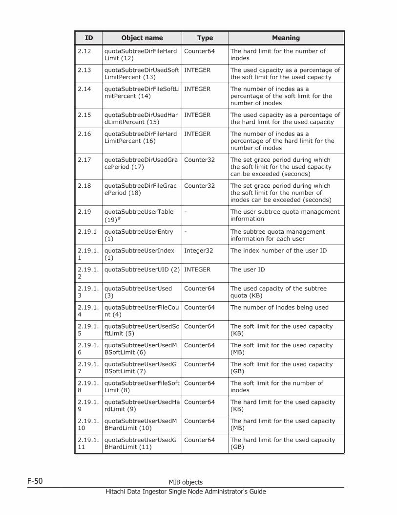
ID Object name Type Meaning
2.12 quotaSubtreeDirFileHardLimit (12)
Counter64 The hard limit for the number ofinodes
2.13 quotaSubtreeDirUsedSoftLimitPercent (13)
INTEGER The used capacity as a percentage ofthe soft limit for the used capacity
2.14 quotaSubtreeDirFileSoftLimitPercent (14)
INTEGER The number of inodes as apercentage of the soft limit for thenumber of inodes
2.15 quotaSubtreeDirUsedHardLimitPercent (15)
INTEGER The used capacity as a percentage ofthe hard limit for the used capacity
2.16 quotaSubtreeDirFileHardLimitPercent (16)
INTEGER The number of inodes as apercentage of the hard limit for thenumber of inodes
2.17 quotaSubtreeDirUsedGracePeriod (17)
Counter32 The set grace period during whichthe soft limit for the used capacitycan be exceeded (seconds)
2.18 quotaSubtreeDirFileGracePeriod (18)
Counter32 The set grace period during whichthe soft limit for the number ofinodes can be exceeded (seconds)
2.19 quotaSubtreeUserTable(19)#
- The user subtree quota managementinformation
2.19.1 quotaSubtreeUserEntry(1)
- The subtree quota managementinformation for each user
2.19.1.1
quotaSubtreeUserIndex(1)
Integer32 The index number of the user ID
2.19.1.2
quotaSubtreeUserUID (2) INTEGER The user ID
2.19.1.3
quotaSubtreeUserUsed(3)
Counter64 The used capacity of the subtreequota (KB)
2.19.1.4
quotaSubtreeUserFileCount (4)
Counter64 The number of inodes being used
2.19.1.5
quotaSubtreeUserUsedSoftLimit (5)
Counter64 The soft limit for the used capacity(KB)
2.19.1.6
quotaSubtreeUserUsedMBSoftLimit (6)
Counter64 The soft limit for the used capacity(MB)
2.19.1.7
quotaSubtreeUserUsedGBSoftLimit (7)
Counter64 The soft limit for the used capacity(GB)
2.19.1.8
quotaSubtreeUserFileSoftLimit (8)
Counter64 The soft limit for the number ofinodes
2.19.1.9
quotaSubtreeUserUsedHardLimit (9)
Counter64 The hard limit for the used capacity(KB)
2.19.1.10
quotaSubtreeUserUsedMBHardLimit (10)
Counter64 The hard limit for the used capacity(MB)
2.19.1.11
quotaSubtreeUserUsedGBHardLimit (11)
Counter64 The hard limit for the used capacity(GB)
F-50 MIB objectsHitachi Data Ingestor Single Node Administrator's Guide
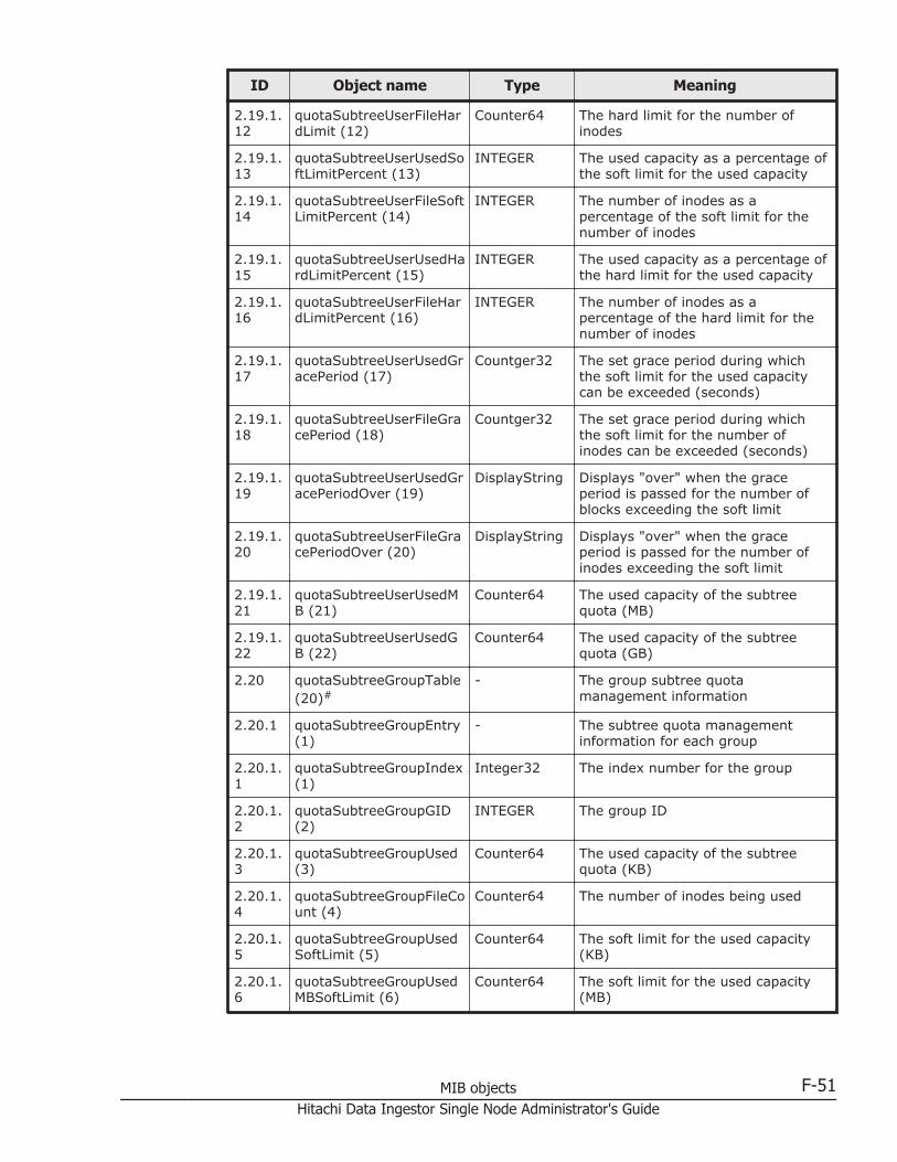
ID Object name Type Meaning
2.19.1.12
quotaSubtreeUserFileHardLimit (12)
Counter64 The hard limit for the number ofinodes
2.19.1.13
quotaSubtreeUserUsedSoftLimitPercent (13)
INTEGER The used capacity as a percentage ofthe soft limit for the used capacity
2.19.1.14
quotaSubtreeUserFileSoftLimitPercent (14)
INTEGER The number of inodes as apercentage of the soft limit for thenumber of inodes
2.19.1.15
quotaSubtreeUserUsedHardLimitPercent (15)
INTEGER The used capacity as a percentage ofthe hard limit for the used capacity
2.19.1.16
quotaSubtreeUserFileHardLimitPercent (16)
INTEGER The number of inodes as apercentage of the hard limit for thenumber of inodes
2.19.1.17
quotaSubtreeUserUsedGracePeriod (17)
Countger32 The set grace period during whichthe soft limit for the used capacitycan be exceeded (seconds)
2.19.1.18
quotaSubtreeUserFileGracePeriod (18)
Countger32 The set grace period during whichthe soft limit for the number ofinodes can be exceeded (seconds)
2.19.1.19
quotaSubtreeUserUsedGracePeriodOver (19)
DisplayString Displays "over" when the graceperiod is passed for the number ofblocks exceeding the soft limit
2.19.1.20
quotaSubtreeUserFileGracePeriodOver (20)
DisplayString Displays "over" when the graceperiod is passed for the number ofinodes exceeding the soft limit
2.19.1.21
quotaSubtreeUserUsedMB (21)
Counter64 The used capacity of the subtreequota (MB)
2.19.1.22
quotaSubtreeUserUsedGB (22)
Counter64 The used capacity of the subtreequota (GB)
2.20 quotaSubtreeGroupTable(20)#
- The group subtree quotamanagement information
2.20.1 quotaSubtreeGroupEntry(1)
- The subtree quota managementinformation for each group
2.20.1.1
quotaSubtreeGroupIndex(1)
Integer32 The index number for the group
2.20.1.2
quotaSubtreeGroupGID(2)
INTEGER The group ID
2.20.1.3
quotaSubtreeGroupUsed(3)
Counter64 The used capacity of the subtreequota (KB)
2.20.1.4
quotaSubtreeGroupFileCount (4)
Counter64 The number of inodes being used
2.20.1.5
quotaSubtreeGroupUsedSoftLimit (5)
Counter64 The soft limit for the used capacity(KB)
2.20.1.6
quotaSubtreeGroupUsedMBSoftLimit (6)
Counter64 The soft limit for the used capacity(MB)
MIB objects F-51Hitachi Data Ingestor Single Node Administrator's Guide
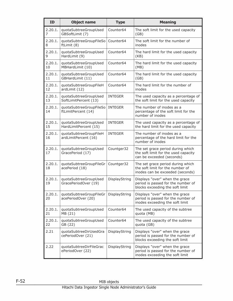
ID Object name Type Meaning
2.20.1.7
quotaSubtreeGroupUsedGBSoftLimit (7)
Counter64 The soft limit for the used capacity(GB)
2.20.1.8
quotaSubtreeGroupFileSoftLimit (8)
Counter64 The soft limit for the number ofinodes
2.20.1.9
quotaSubtreeGroupUsedHardLimit (9)
Counter64 The hard limit for the used capacity(KB)
2.20.1.10
quotaSubtreeGroupUsedMBHardLimit (10)
Counter64 The hard limit for the used capacity(MB)
2.20.1.11
quotaSubtreeGroupUsedGBHardLimit (11)
Counter64 The hard limit for the used capacity(GB)
2.20.1.12
quotaSubtreeGroupFileHardLimit (12)
Counter64 The hard limit for the number ofinodes
2.20.1.13
quotaSubtreeGroupUsedSoftLimitPercent (13)
INTEGER The used capacity as a percentage ofthe soft limit for the used capacity
2.20.1.14
quotaSubtreeGroupFileSoftLimitPercent (14)
INTEGER The number of inodes as apercentage of the soft limit for thenumber of inodes
2.20.1.15
quotaSubtreeGroupUsedHardLimitPercent (15)
INTEGER The used capacity as a percentage ofthe hard limit for the used capacity
2.20.1.16
quotaSubtreeGroupFileHardLimitPercent (16)
INTEGER The number of inodes as apercentage of the hard limit for thenumber of inodes
2.20.1.17
quotaSubtreeGroupUsedGracePeriod (17)
Countger32 The set grace period during whichthe soft limit for the used capacitycan be exceeded (seconds)
2.20.1.18
quotaSubtreeGroupFileGracePeriod (18)
Countger32 The set grace period during whichthe soft limit for the number ofinodes can be exceeded (seconds)
2.20.1.19
quotaSubtreeGroupUsedGracePeriodOver (19)
DisplayString Displays "over" when the graceperiod is passed for the number ofblocks exceeding the soft limit
2.20.1.20
quotaSubtreeGroupFileGracePeriodOver (20)
DisplayString Displays "over" when the graceperiod is passed for the number ofinodes exceeding the soft limit
2.20.1.21
quotaSubtreeGroupUsedMB (21)
Counter64 The used capacity of the subtreequota (MB)
2.20.1.22
quotaSubtreeGroupUsedGB (22)
Counter64 The used capacity of the subtreequota (GB)
2.21 quotaSubtreeDirUsedGracePeriodOver (21)
DisplayString Displays "over" when the graceperiod is passed for the number ofblocks exceeding the soft limit
2.22 quotaSubtreeDirFileGracePeriodOver (22)
DisplayString Displays "over" when the graceperiod is passed for the number ofinodes exceeding the soft limit
F-52 MIB objectsHitachi Data Ingestor Single Node Administrator's Guide
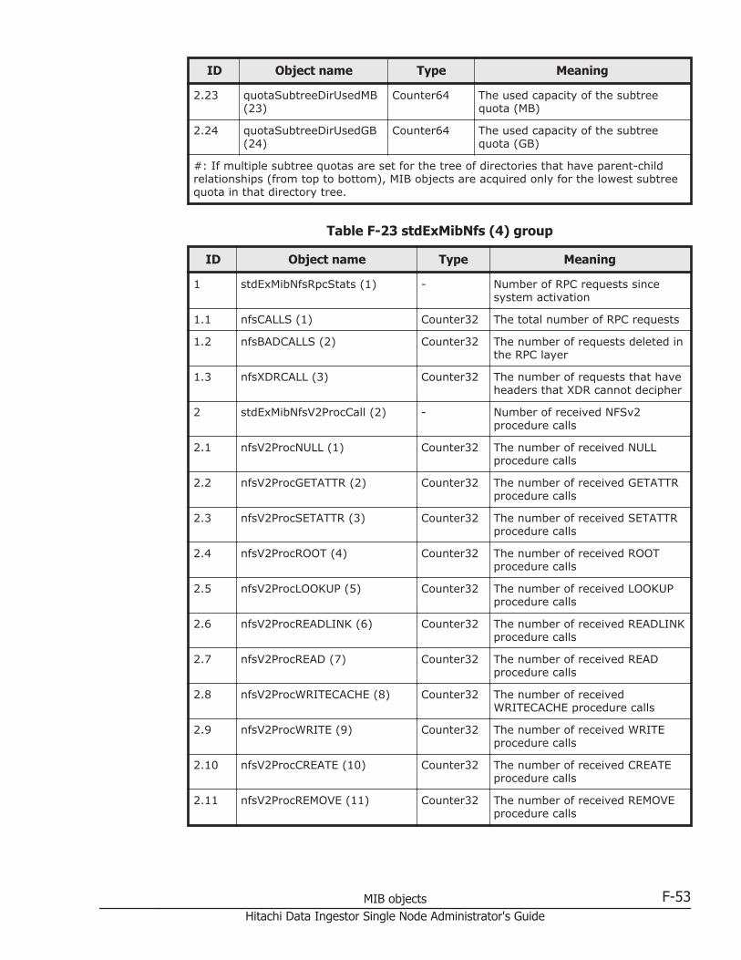
ID Object name Type Meaning
2.23 quotaSubtreeDirUsedMB(23)
Counter64 The used capacity of the subtreequota (MB)
2.24 quotaSubtreeDirUsedGB(24)
Counter64 The used capacity of the subtreequota (GB)
#: If multiple subtree quotas are set for the tree of directories that have parent-childrelationships (from top to bottom), MIB objects are acquired only for the lowest subtreequota in that directory tree.
Table F-23 stdExMibNfs (4) group
ID Object name Type Meaning
1 stdExMibNfsRpcStats (1) - Number of RPC requests sincesystem activation
1.1 nfsCALLS (1) Counter32 The total number of RPC requests
1.2 nfsBADCALLS (2) Counter32 The number of requests deleted inthe RPC layer
1.3 nfsXDRCALL (3) Counter32 The number of requests that haveheaders that XDR cannot decipher
2 stdExMibNfsV2ProcCall (2) - Number of received NFSv2procedure calls
2.1 nfsV2ProcNULL (1) Counter32 The number of received NULLprocedure calls
2.2 nfsV2ProcGETATTR (2) Counter32 The number of received GETATTRprocedure calls
2.3 nfsV2ProcSETATTR (3) Counter32 The number of received SETATTRprocedure calls
2.4 nfsV2ProcROOT (4) Counter32 The number of received ROOTprocedure calls
2.5 nfsV2ProcLOOKUP (5) Counter32 The number of received LOOKUPprocedure calls
2.6 nfsV2ProcREADLINK (6) Counter32 The number of received READLINKprocedure calls
2.7 nfsV2ProcREAD (7) Counter32 The number of received READprocedure calls
2.8 nfsV2ProcWRITECACHE (8) Counter32 The number of receivedWRITECACHE procedure calls
2.9 nfsV2ProcWRITE (9) Counter32 The number of received WRITEprocedure calls
2.10 nfsV2ProcCREATE (10) Counter32 The number of received CREATEprocedure calls
2.11 nfsV2ProcREMOVE (11) Counter32 The number of received REMOVEprocedure calls
MIB objects F-53Hitachi Data Ingestor Single Node Administrator's Guide
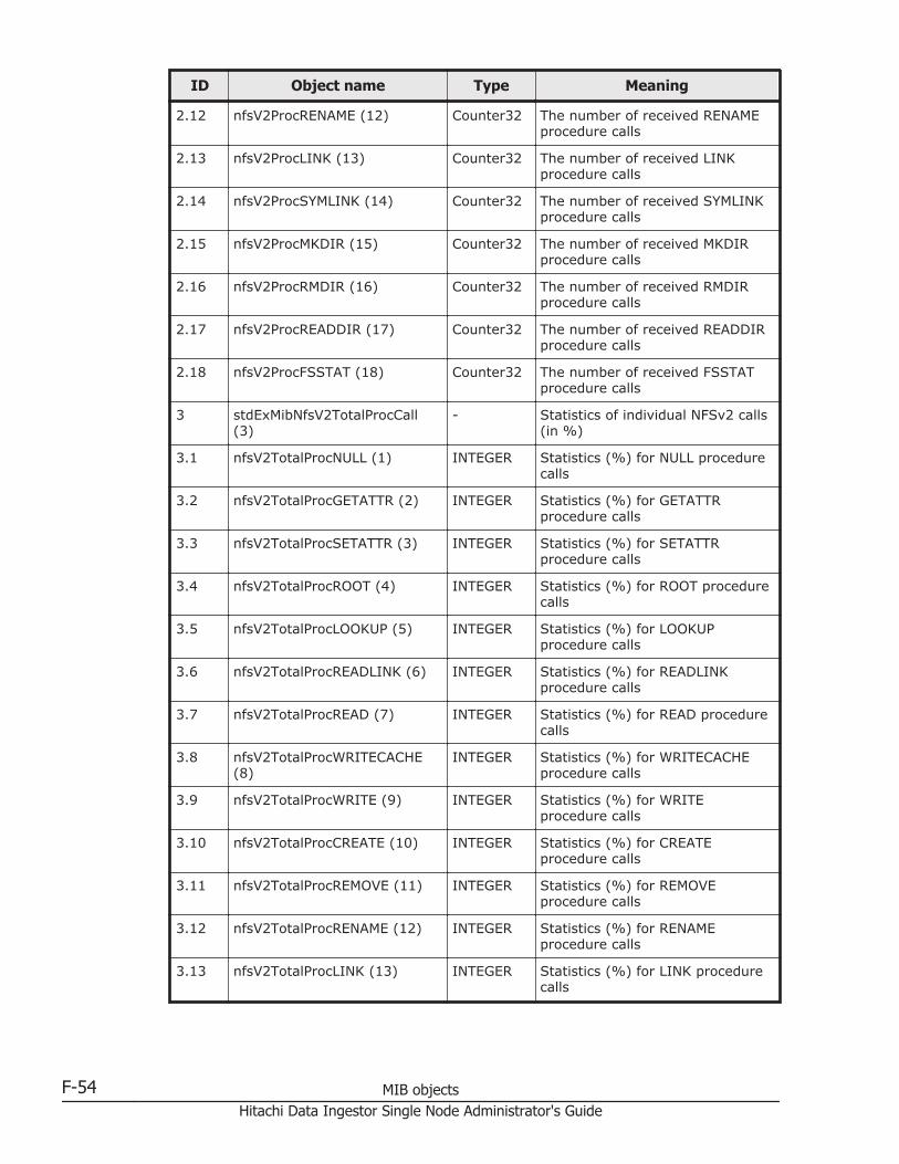
ID Object name Type Meaning
2.12 nfsV2ProcRENAME (12) Counter32 The number of received RENAMEprocedure calls
2.13 nfsV2ProcLINK (13) Counter32 The number of received LINKprocedure calls
2.14 nfsV2ProcSYMLINK (14) Counter32 The number of received SYMLINKprocedure calls
2.15 nfsV2ProcMKDIR (15) Counter32 The number of received MKDIRprocedure calls
2.16 nfsV2ProcRMDIR (16) Counter32 The number of received RMDIRprocedure calls
2.17 nfsV2ProcREADDIR (17) Counter32 The number of received READDIRprocedure calls
2.18 nfsV2ProcFSSTAT (18) Counter32 The number of received FSSTATprocedure calls
3 stdExMibNfsV2TotalProcCall(3)
- Statistics of individual NFSv2 calls(in %)
3.1 nfsV2TotalProcNULL (1) INTEGER Statistics (%) for NULL procedurecalls
3.2 nfsV2TotalProcGETATTR (2) INTEGER Statistics (%) for GETATTRprocedure calls
3.3 nfsV2TotalProcSETATTR (3) INTEGER Statistics (%) for SETATTRprocedure calls
3.4 nfsV2TotalProcROOT (4) INTEGER Statistics (%) for ROOT procedurecalls
3.5 nfsV2TotalProcLOOKUP (5) INTEGER Statistics (%) for LOOKUPprocedure calls
3.6 nfsV2TotalProcREADLINK (6) INTEGER Statistics (%) for READLINKprocedure calls
3.7 nfsV2TotalProcREAD (7) INTEGER Statistics (%) for READ procedurecalls
3.8 nfsV2TotalProcWRITECACHE(8)
INTEGER Statistics (%) for WRITECACHEprocedure calls
3.9 nfsV2TotalProcWRITE (9) INTEGER Statistics (%) for WRITEprocedure calls
3.10 nfsV2TotalProcCREATE (10) INTEGER Statistics (%) for CREATEprocedure calls
3.11 nfsV2TotalProcREMOVE (11) INTEGER Statistics (%) for REMOVEprocedure calls
3.12 nfsV2TotalProcRENAME (12) INTEGER Statistics (%) for RENAMEprocedure calls
3.13 nfsV2TotalProcLINK (13) INTEGER Statistics (%) for LINK procedurecalls
F-54 MIB objectsHitachi Data Ingestor Single Node Administrator's Guide

ID Object name Type Meaning
3.14 nfsV2TotalProcSYMLINK (14) INTEGER Statistics (%) for SYMLINKprocedure calls
3.15 nfsV2TotalProcMKDIR (15) INTEGER Statistics (%) for MKDIRprocedure calls
3.16 nfsV2TotalProcRMDIR (16) INTEGER Statistics (%) for RMDIRprocedure calls
3.17 nfsV2TotalProcREADDIR (17) INTEGER Statistics (%) for READDIRprocedure calls
3.18 nfsV2TotalProcFSSTAT (18) INTEGER Statistics (%) for FSSTATprocedure calls
4 stdExMibNfsV3ProcCall (4) - Number of received NFSv3procedure calls
4.1 nfsV3ProcNULL (1) Counter32 The number of received NULLprocedure calls
4.2 nfsV3ProcGETATTR (2) Counter32 The number of received GETATTRprocedure calls
4.3 nfsV3ProcSETATTR (3) Counter32 The number of received SETATTRprocedure calls
4.4 nfsV3ProcLOOKUP (4) Counter32 The number of received LOOKUPprocedure calls
4.5 nfsV3ProcACCESS (5) Counter32 The number of received ACCESSprocedure calls
4.6 nfsV3ProcREADLINK (6) Counter32 The number of received READLINKprocedure calls
4.7 nfsV3ProcREAD (7) Counter32 The number of received READprocedure calls
4.8 nfsV3ProcWRITE (8) Counter32 The number of received WRITEprocedure calls
4.9 nfsV3ProcCREATE (9) Counter32 The number of received CREATEprocedure calls
4.10 nfsV3ProcMKDIR (10) Counter32 The number of receivedWRITECACHE procedure calls
4.11 nfsV3ProcSYMLINK (11) Counter32 The number of received SYMLINKprocedure calls
4.12 nfsV3ProcMKNOD (12) Counter32 The number of received MKNODprocedure calls
4.13 nfsV3ProcREMOVE (13) Counter32 The number of received REMOVEprocedure calls
4.14 nfsV3ProcRMDIR (14) Counter32 The number of received RMDIRprocedure calls
4.15 nfsV3ProcRENAME (15) Counter32 The number of received RENAMEprocedure calls
MIB objects F-55Hitachi Data Ingestor Single Node Administrator's Guide
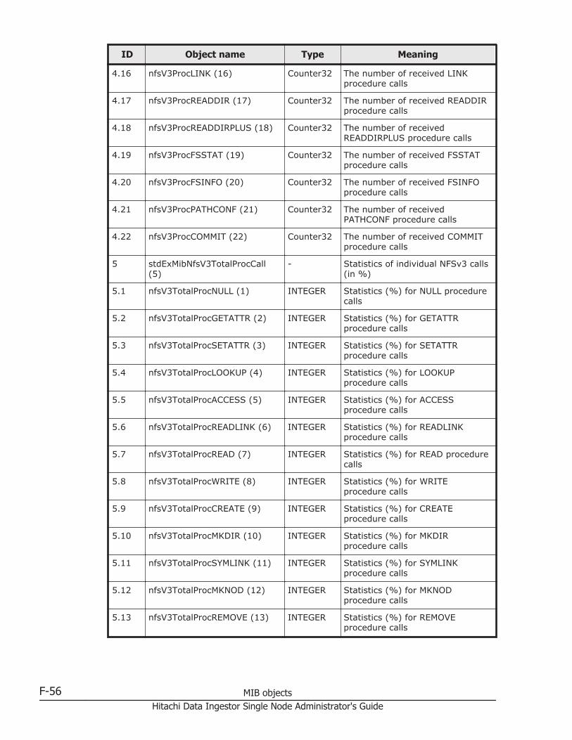
ID Object name Type Meaning
4.16 nfsV3ProcLINK (16) Counter32 The number of received LINKprocedure calls
4.17 nfsV3ProcREADDIR (17) Counter32 The number of received READDIRprocedure calls
4.18 nfsV3ProcREADDIRPLUS (18) Counter32 The number of receivedREADDIRPLUS procedure calls
4.19 nfsV3ProcFSSTAT (19) Counter32 The number of received FSSTATprocedure calls
4.20 nfsV3ProcFSINFO (20) Counter32 The number of received FSINFOprocedure calls
4.21 nfsV3ProcPATHCONF (21) Counter32 The number of receivedPATHCONF procedure calls
4.22 nfsV3ProcCOMMIT (22) Counter32 The number of received COMMITprocedure calls
5 stdExMibNfsV3TotalProcCall(5)
- Statistics of individual NFSv3 calls(in %)
5.1 nfsV3TotalProcNULL (1) INTEGER Statistics (%) for NULL procedurecalls
5.2 nfsV3TotalProcGETATTR (2) INTEGER Statistics (%) for GETATTRprocedure calls
5.3 nfsV3TotalProcSETATTR (3) INTEGER Statistics (%) for SETATTRprocedure calls
5.4 nfsV3TotalProcLOOKUP (4) INTEGER Statistics (%) for LOOKUPprocedure calls
5.5 nfsV3TotalProcACCESS (5) INTEGER Statistics (%) for ACCESSprocedure calls
5.6 nfsV3TotalProcREADLINK (6) INTEGER Statistics (%) for READLINKprocedure calls
5.7 nfsV3TotalProcREAD (7) INTEGER Statistics (%) for READ procedurecalls
5.8 nfsV3TotalProcWRITE (8) INTEGER Statistics (%) for WRITEprocedure calls
5.9 nfsV3TotalProcCREATE (9) INTEGER Statistics (%) for CREATEprocedure calls
5.10 nfsV3TotalProcMKDIR (10) INTEGER Statistics (%) for MKDIRprocedure calls
5.11 nfsV3TotalProcSYMLINK (11) INTEGER Statistics (%) for SYMLINKprocedure calls
5.12 nfsV3TotalProcMKNOD (12) INTEGER Statistics (%) for MKNODprocedure calls
5.13 nfsV3TotalProcREMOVE (13) INTEGER Statistics (%) for REMOVEprocedure calls
F-56 MIB objectsHitachi Data Ingestor Single Node Administrator's Guide
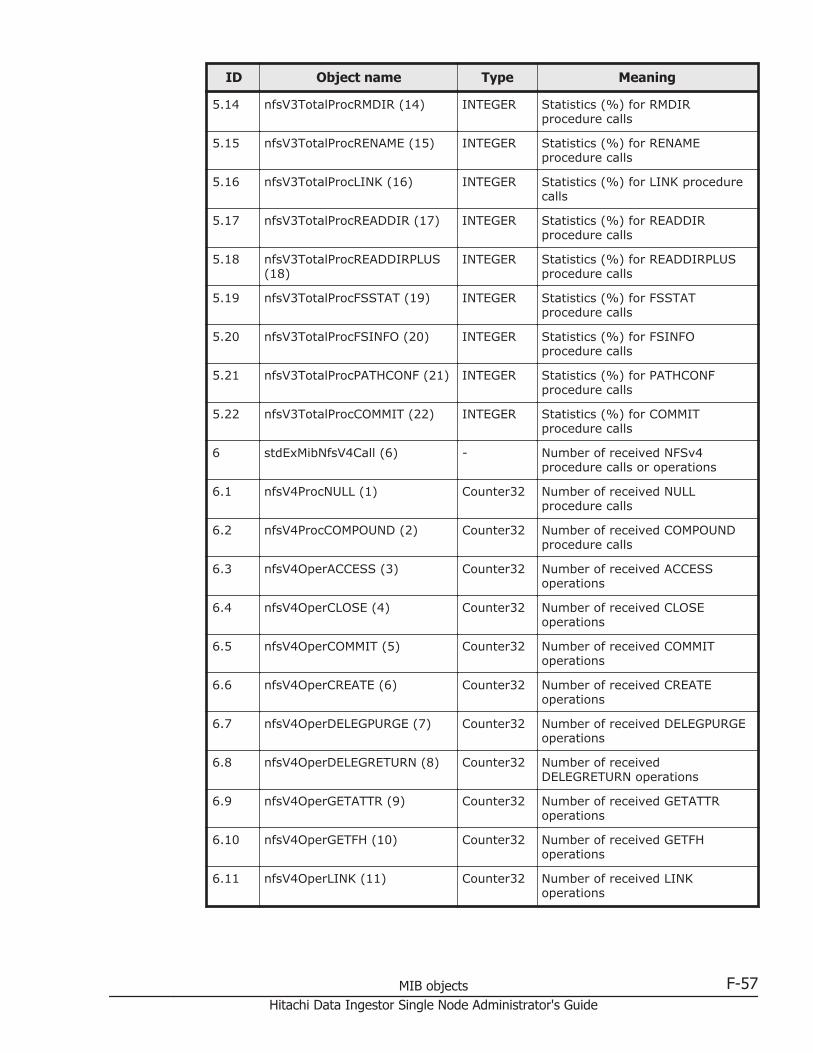
ID Object name Type Meaning
5.14 nfsV3TotalProcRMDIR (14) INTEGER Statistics (%) for RMDIRprocedure calls
5.15 nfsV3TotalProcRENAME (15) INTEGER Statistics (%) for RENAMEprocedure calls
5.16 nfsV3TotalProcLINK (16) INTEGER Statistics (%) for LINK procedurecalls
5.17 nfsV3TotalProcREADDIR (17) INTEGER Statistics (%) for READDIRprocedure calls
5.18 nfsV3TotalProcREADDIRPLUS(18)
INTEGER Statistics (%) for READDIRPLUSprocedure calls
5.19 nfsV3TotalProcFSSTAT (19) INTEGER Statistics (%) for FSSTATprocedure calls
5.20 nfsV3TotalProcFSINFO (20) INTEGER Statistics (%) for FSINFOprocedure calls
5.21 nfsV3TotalProcPATHCONF (21) INTEGER Statistics (%) for PATHCONFprocedure calls
5.22 nfsV3TotalProcCOMMIT (22) INTEGER Statistics (%) for COMMITprocedure calls
6 stdExMibNfsV4Call (6) - Number of received NFSv4procedure calls or operations
6.1 nfsV4ProcNULL (1) Counter32 Number of received NULLprocedure calls
6.2 nfsV4ProcCOMPOUND (2) Counter32 Number of received COMPOUNDprocedure calls
6.3 nfsV4OperACCESS (3) Counter32 Number of received ACCESSoperations
6.4 nfsV4OperCLOSE (4) Counter32 Number of received CLOSEoperations
6.5 nfsV4OperCOMMIT (5) Counter32 Number of received COMMIToperations
6.6 nfsV4OperCREATE (6) Counter32 Number of received CREATEoperations
6.7 nfsV4OperDELEGPURGE (7) Counter32 Number of received DELEGPURGEoperations
6.8 nfsV4OperDELEGRETURN (8) Counter32 Number of receivedDELEGRETURN operations
6.9 nfsV4OperGETATTR (9) Counter32 Number of received GETATTRoperations
6.10 nfsV4OperGETFH (10) Counter32 Number of received GETFHoperations
6.11 nfsV4OperLINK (11) Counter32 Number of received LINKoperations
MIB objects F-57Hitachi Data Ingestor Single Node Administrator's Guide
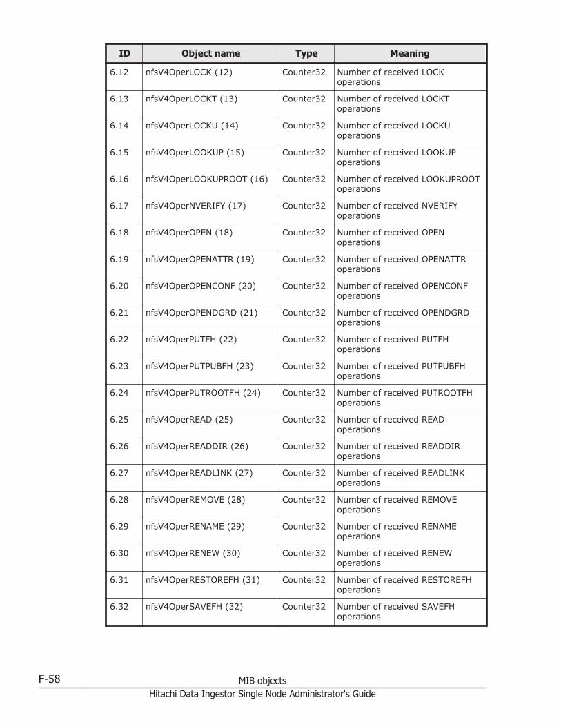
ID Object name Type Meaning
6.12 nfsV4OperLOCK (12) Counter32 Number of received LOCKoperations
6.13 nfsV4OperLOCKT (13) Counter32 Number of received LOCKToperations
6.14 nfsV4OperLOCKU (14) Counter32 Number of received LOCKUoperations
6.15 nfsV4OperLOOKUP (15) Counter32 Number of received LOOKUPoperations
6.16 nfsV4OperLOOKUPROOT (16) Counter32 Number of received LOOKUPROOToperations
6.17 nfsV4OperNVERIFY (17) Counter32 Number of received NVERIFYoperations
6.18 nfsV4OperOPEN (18) Counter32 Number of received OPENoperations
6.19 nfsV4OperOPENATTR (19) Counter32 Number of received OPENATTRoperations
6.20 nfsV4OperOPENCONF (20) Counter32 Number of received OPENCONFoperations
6.21 nfsV4OperOPENDGRD (21) Counter32 Number of received OPENDGRDoperations
6.22 nfsV4OperPUTFH (22) Counter32 Number of received PUTFHoperations
6.23 nfsV4OperPUTPUBFH (23) Counter32 Number of received PUTPUBFHoperations
6.24 nfsV4OperPUTROOTFH (24) Counter32 Number of received PUTROOTFHoperations
6.25 nfsV4OperREAD (25) Counter32 Number of received READoperations
6.26 nfsV4OperREADDIR (26) Counter32 Number of received READDIRoperations
6.27 nfsV4OperREADLINK (27) Counter32 Number of received READLINKoperations
6.28 nfsV4OperREMOVE (28) Counter32 Number of received REMOVEoperations
6.29 nfsV4OperRENAME (29) Counter32 Number of received RENAMEoperations
6.30 nfsV4OperRENEW (30) Counter32 Number of received RENEWoperations
6.31 nfsV4OperRESTOREFH (31) Counter32 Number of received RESTOREFHoperations
6.32 nfsV4OperSAVEFH (32) Counter32 Number of received SAVEFHoperations
F-58 MIB objectsHitachi Data Ingestor Single Node Administrator's Guide
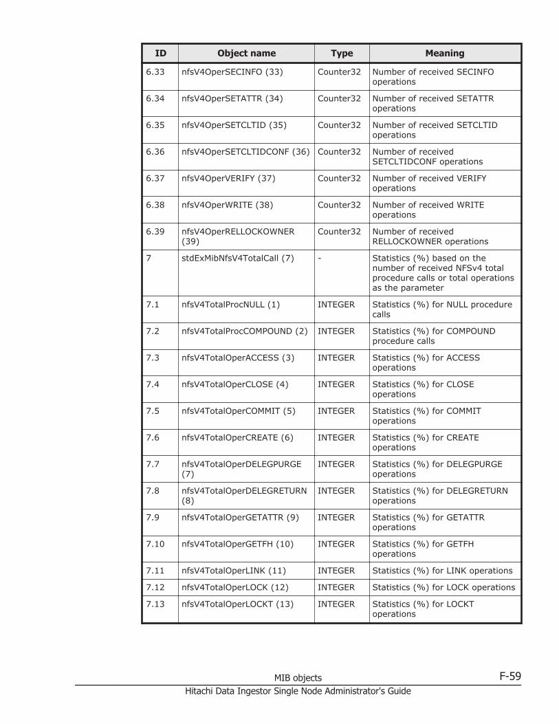
ID Object name Type Meaning
6.33 nfsV4OperSECINFO (33) Counter32 Number of received SECINFOoperations
6.34 nfsV4OperSETATTR (34) Counter32 Number of received SETATTRoperations
6.35 nfsV4OperSETCLTID (35) Counter32 Number of received SETCLTIDoperations
6.36 nfsV4OperSETCLTIDCONF (36) Counter32 Number of receivedSETCLTIDCONF operations
6.37 nfsV4OperVERIFY (37) Counter32 Number of received VERIFYoperations
6.38 nfsV4OperWRITE (38) Counter32 Number of received WRITEoperations
6.39 nfsV4OperRELLOCKOWNER(39)
Counter32 Number of receivedRELLOCKOWNER operations
7 stdExMibNfsV4TotalCall (7) - Statistics (%) based on thenumber of received NFSv4 totalprocedure calls or total operationsas the parameter
7.1 nfsV4TotalProcNULL (1) INTEGER Statistics (%) for NULL procedurecalls
7.2 nfsV4TotalProcCOMPOUND (2) INTEGER Statistics (%) for COMPOUNDprocedure calls
7.3 nfsV4TotalOperACCESS (3) INTEGER Statistics (%) for ACCESSoperations
7.4 nfsV4TotalOperCLOSE (4) INTEGER Statistics (%) for CLOSEoperations
7.5 nfsV4TotalOperCOMMIT (5) INTEGER Statistics (%) for COMMIToperations
7.6 nfsV4TotalOperCREATE (6) INTEGER Statistics (%) for CREATEoperations
7.7 nfsV4TotalOperDELEGPURGE(7)
INTEGER Statistics (%) for DELEGPURGEoperations
7.8 nfsV4TotalOperDELEGRETURN(8)
INTEGER Statistics (%) for DELEGRETURNoperations
7.9 nfsV4TotalOperGETATTR (9) INTEGER Statistics (%) for GETATTRoperations
7.10 nfsV4TotalOperGETFH (10) INTEGER Statistics (%) for GETFHoperations
7.11 nfsV4TotalOperLINK (11) INTEGER Statistics (%) for LINK operations
7.12 nfsV4TotalOperLOCK (12) INTEGER Statistics (%) for LOCK operations
7.13 nfsV4TotalOperLOCKT (13) INTEGER Statistics (%) for LOCKToperations
MIB objects F-59Hitachi Data Ingestor Single Node Administrator's Guide
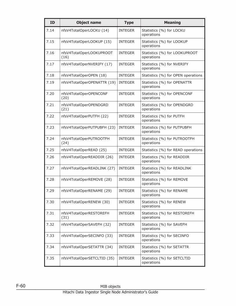
ID Object name Type Meaning
7.14 nfsV4TotalOperLOCKU (14) INTEGER Statistics (%) for LOCKUoperations
7.15 nfsV4TotalOperLOOKUP (15) INTEGER Statistics (%) for LOOKUPoperations
7.16 nfsV4TotalOperLOOKUPROOT(16)
INTEGER Statistics (%) for LOOKUPROOToperations
7.17 nfsV4TotalOperNVERIFY (17) INTEGER Statistics (%) for NVERIFYoperations
7.18 nfsV4TotalOperOPEN (18) INTEGER Statistics (%) for OPEN operations
7.19 nfsV4TotalOperOPENATTR (19) INTEGER Statistics (%) for OPENATTRoperations
7.20 nfsV4TotalOperOPENCONF(20)
INTEGER Statistics (%) for OPENCONFoperations
7.21 nfsV4TotalOperOPENDGRD(21)
INTEGER Statistics (%) for OPENDGRDoperations
7.22 nfsV4TotalOperPUTFH (22) INTEGER Statistics (%) for PUTFHoperations
7.23 nfsV4TotalOperPUTPUBFH (23) INTEGER Statistics (%) for PUTPUBFHoperations
7.24 nfsV4TotalOperPUTROOTFH(24)
INTEGER Statistics (%) for PUTROOTFHoperations
7.25 nfsV4TotalOperREAD (25) INTEGER Statistics (%) for READ operations
7.26 nfsV4TotalOperREADDIR (26) INTEGER Statistics (%) for READDIRoperations
7.27 nfsV4TotalOperREADLINK (27) INTEGER Statistics (%) for READLINKoperations
7.28 nfsV4TotalOperREMOVE (28) INTEGER Statistics (%) for REMOVEoperations
7.29 nfsV4TotalOperRENAME (29) INTEGER Statistics (%) for RENAMEoperations
7.30 nfsV4TotalOperRENEW (30) INTEGER Statistics (%) for RENEWoperations
7.31 nfsV4TotalOperRESTOREFH(31)
INTEGER Statistics (%) for RESTOREFHoperations
7.32 nfsV4TotalOperSAVEFH (32) INTEGER Statistics (%) for SAVEFHoperations
7.33 nfsV4TotalOperSECINFO (33) INTEGER Statistics (%) for SECINFOoperations
7.34 nfsV4TotalOperSETATTR (34) INTEGER Statistics (%) for SETATTRoperations
7.35 nfsV4TotalOperSETCLTID (35) INTEGER Statistics (%) for SETCLTIDoperations
F-60 MIB objectsHitachi Data Ingestor Single Node Administrator's Guide

ID Object name Type Meaning
7.36 nfsV4TotalOperSETCLTIDCONF(36)
INTEGER Statistics (%) for SETCLTIDCONFoperations
7.37 nfsV4TotalOperVERIFY (37) INTEGER Statistics (%) for VERIFYoperations
7.38 nfsV4TotalOperWRITE (38) INTEGER Statistics (%) for WRITEoperations
7.39 nfsV4TotalOperRELLOCKOWNER (39)
INTEGER Statistics (%) for RELLOCKOWNERoperations
Table F-24 stdExMibCifs (5) group
ID Object name Type Meaning
1 stdExMibCifsItem (1) - CIFS item
1.1 cifsWorkGroup (1) DisplayString Workgroup name
1.2 cifsSeverComment (2) DisplayString Server comment#1
1.3 cifsSecurity (3) DisplayString Authentication mode
1.4 cifsPasswordServer (4) DisplayString Authentication server#1
1.5 cifsSharesCount (5) INTEGER The number of current CIFSshares
1.6 cifsSessionCount (6) Counter32 The number of current sessions#2
#1: No more than 255 characters are displayed, and the 256th and subsequentcharacters are truncated.
#2: The CIFS sessions established by specifying a NetBIOS name and those establishedby specifying an IP address are counted separately even when the sessions areestablished concurrently from the same client.
Table F-25 stdExMibNetwork (6) group
ID Object name Type Meaning
1 stdExMibIPAddressTable (1) - IP address management
1.1 ipAddressEntry (1)#1 - Details about each IP address
1.1.1 ipAddressIFIndex (1) Integer32 Index number for each networkinterface
1.1.2 ipAddressAddr (2)#2 IpAddress IP address
1.1.3 ipAddressIFName (3) DisplayString
Network interface name
1.1.4 ipv6IpAddressAddr (4) DisplayString
IP address (IPv6)
2 stdExMibDefaultGateway (2) IpAddress Default gateway
MIB objects F-61Hitachi Data Ingestor Single Node Administrator's Guide
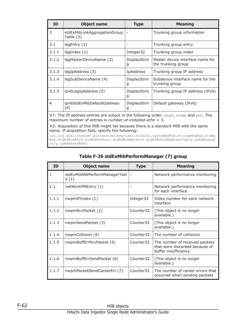
ID Object name Type Meaning
3 stdExMibLinkAggregationGroupTable (3)
- Trunking group information
3.1 lagEntry (1) - Trunking group entry
3.1.1 lagIndex (1) Integer32 Trunking group index
3.1.2 lagMasterDeviceName (2) DisplayString
Master device interface name forthe trunking group
3.1.3 lagIpAddress (3) IpAddress Trunking group IP address
3.1.4 lagSubDeviceName (4) DisplayString
Subdevice interface name for thetrunking group
3.1.5 ipv6LagIpAddress (5) DisplayString
Trunking group IP address (IPv6)
4 ipv6StdExMibDefaultGateway(4)
DisplayString
Default gateway (IPv6)
#1: The IP address entries are output in the following order: mng0, ethn, and pm0. Themaximum number of entries is number-of-installed-ethn + 3.
#2: Acquisition of this MIB might fail because there is a standard MIB with the samename. If acquisition fails, specify the following:iso.org.dod.internet.private.enterprises.hitachi.systemExMib.storageExMib.stdExMib.stdExMibRAID.stdExMibRoot.stdExMibNetwork.stdExMibIPAddressTable.ipAddressEntry.ipAddressAddr
Table F-26 stdExMibPerformManager (7) group
ID Object name Type Meaning
1 stdExMibNWPerformManagerTable (1)
- Network performance monitoring
1.1 netWorkPMEntry (1) - Network performance monitoringfor each interface
1.1.1 nwpmIFIndex (1) Integer32 Index number for each networkinterface
1.1.2 nwpmRcvPacket (2) Counter32 (This object is no longeravailable.)
1.1.3 nwpmSendPacket (3) Counter32 (This object is no longeravailable.)
1.1.4 nwpmCollision (4) Counter32 The number of collisions
1.1.5 nwpmBuffErrRcvPacket (5) Counter32 The number of received packetsthat were discarded because ofbuffer insufficiency
1.1.6 nwpmBuffErrSendPacket (6) Counter32 (This object is no longeravailable.)
1.1.7 nwpmPacketSendCareerErr (7) Counter32 The number of career errors thatoccurred when sending packets
F-62 MIB objectsHitachi Data Ingestor Single Node Administrator's Guide

ID Object name Type Meaning
1.1.8 nwpmFrmAlignmentErr (8) Counter32 The number of frame alignmenterrors
1.1.9 nwpmFIFOSendOverRunErr (9) Counter32 (This object is no longeravailable.)
1.1.10 nwpmFIFORcvOverRunErr (10) Counter32 The number of FIFO overrunerrors (receiving)
2 stdExMibLagPerformManagerTable (2)
- Performance monitoringinformation for the trunkinggroup
2.1 lagPerformManagerEntry (1) - Performance monitoring entryfor the trunking group
2.1.1 lagpmIFIndex (1) Integer32 Trunking group interface index
2.1.2 lagpmRcvPacket (2) Counter32 Number of received compressedpackets for the trunking group
2.1.3 lagpmSendPacket (3) Counter32 Number of sent compressedpackets for the trunking group
2.1.4 lagpmCollision (4) Counter32 Number of times a collisionoccurred for the trunking group
2.1.5 lagpmBuffErrRcvPacket (5) Counter32 Number of received packetsdiscarded because of aninsufficiency for the trunkinggroup buffer
2.1.6 lagpmBuffErrSendPacket (6) Counter32 Number of sent packetsdiscarded because of aninsufficiency for the trunkinggroup buffer
2.1.7 lagpmPacketSendCareerErr (7) Counter32 Number of carrier errors thatoccurred during sending oftrunking group packets
2.1.8 lagpmFrmAlignmentErr (8) Counter32 Number of frame alignmenterrors for the trunking group
2.1.9 lagpmFIFOSendOverRunErr (9) Counter32 Number of FIFO overrun errorsfor the trunking group (duringsending)
2.1.10 lagpmFIFORcvOverRunErr (10) Counter32 Number of FIFO overrun errorsfor the trunking group (duringreceiving)
Table F-27 stdExMibFileSystem (11) group
ID Object name Type Meaning
1 fileSystemTable (1) - File systems management
1.1 fileSystemEntry (1) - Management information for each filesystem
MIB objects F-63Hitachi Data Ingestor Single Node Administrator's Guide
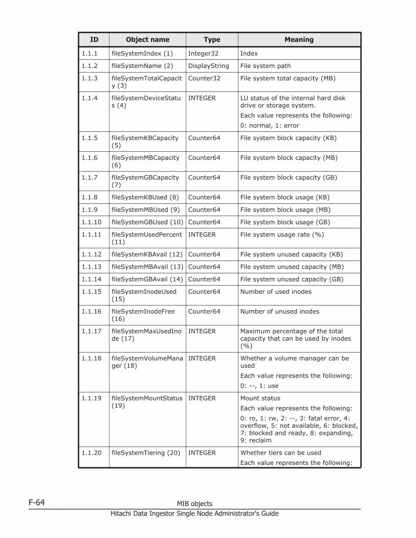
ID Object name Type Meaning
1.1.1 fileSystemIndex (1) Integer32 Index
1.1.2 fileSystemName (2) DisplayString File system path
1.1.3 fileSystemTotalCapacity (3)
Counter32 File system total capacity (MB)
1.1.4 fileSystemDeviceStatus (4)
INTEGER LU status of the internal hard diskdrive or storage system.
Each value represents the following:
0: normal, 1: error
1.1.5 fileSystemKBCapacity(5)
Counter64 File system block capacity (KB)
1.1.6 fileSystemMBCapacity(6)
Counter64 File system block capacity (MB)
1.1.7 fileSystemGBCapacity(7)
Counter64 File system block capacity (GB)
1.1.8 fileSystemKBUsed (8) Counter64 File system block usage (KB)
1.1.9 fileSystemMBUsed (9) Counter64 File system block usage (MB)
1.1.10 fileSystemGBUsed (10) Counter64 File system block usage (GB)
1.1.11 fileSystemUsedPercent(11)
INTEGER File system usage rate (%)
1.1.12 fileSystemKBAvail (12) Counter64 File system unused capacity (KB)
1.1.13 fileSystemMBAvail (13) Counter64 File system unused capacity (MB)
1.1.14 fileSystemGBAvail (14) Counter64 File system unused capacity (GB)
1.1.15 fileSystemInodeUsed(15)
Counter64 Number of used inodes
1.1.16 fileSystemInodeFree(16)
Counter64 Number of unused inodes
1.1.17 fileSystemMaxUsedInode (17)
INTEGER Maximum percentage of the totalcapacity that can be used by inodes(%)
1.1.18 fileSystemVolumeManager (18)
INTEGER Whether a volume manager can beused
Each value represents the following:
0: --, 1: use
1.1.19 fileSystemMountStatus(19)
INTEGER Mount status
Each value represents the following:
0: ro, 1: rw, 2: --, 3: fatal error, 4:overflow, 5: not available, 6: blocked,7: blocked and ready, 8: expanding,9: reclaim
1.1.20 fileSystemTiering (20) INTEGER Whether tiers can be used
Each value represents the following:
F-64 MIB objectsHitachi Data Ingestor Single Node Administrator's Guide

ID Object name Type Meaning
0: --, 1: use
2 fileSystemLUInfoTable(2)
- Information about the LUs that makeup the file system.
2.1 fileSystemLUInfoEntry(1)
- Information about an LU that makesup the file system.
2.1.1 fileSystemLUInfoIndex(1)
Integer32 Index
2.1.2 fileSystemLUInfoDevice (2)
DisplayString Name of the LU that makes up thefile system.
2.1.3 fileSystemLUInfoFSName (3)
DisplayString File system name
2.1.4 fileSystemLUInfoDeviceInfo (4)
INTEGER Storage device information
Each value represents the following:
0: P-vol, 1: D-vol
2.1.5 fileSystemLUInfoSerial(5)
DisplayString Serial number
2.1.6 fileSystemLUInfoDataPool (6)
DisplayString DP number for a data pool thatmakes up the file system
Table F-28 stdExMibHDPPool (12) group
ID Object name Type Meaning
1 hdpPoolTable (1) - Pool management information
1.1 hdpPoolEntry (1) - Management information for eachpool
1.1.1 hdpPoolIndex (1) Integer32 Index
1.1.2 hdpPoolNumber (2) DisplayString Pool number
1.1.3 hdpPoolSerialNumber(3)
DisplayString Serial number
1.1.4 hdpPoolDrive (4) INTEGER Drive type
Each value represents the following:
0: FC/SAS, 1: SATA, 2: SSD, 3:SAS7K, 99: -
1.1.5 hdpPoolTotal (5) Counter32 Total pool capacity (GB)
1.1.6 hdpPoolUsed (6) Counter32 Used pool capacity (GB)
1.1.7 hdpPoolFree (7) Counter32 Unused pool capacity (GB)
1.1.8 hdpPoolUsedPercent(8)
INTEGER Pool usage rate (%)
1.1.9 hdpPoolEarlyAlertPercent (9)
INTEGER Warning threshold (%)
MIB objects F-65Hitachi Data Ingestor Single Node Administrator's Guide
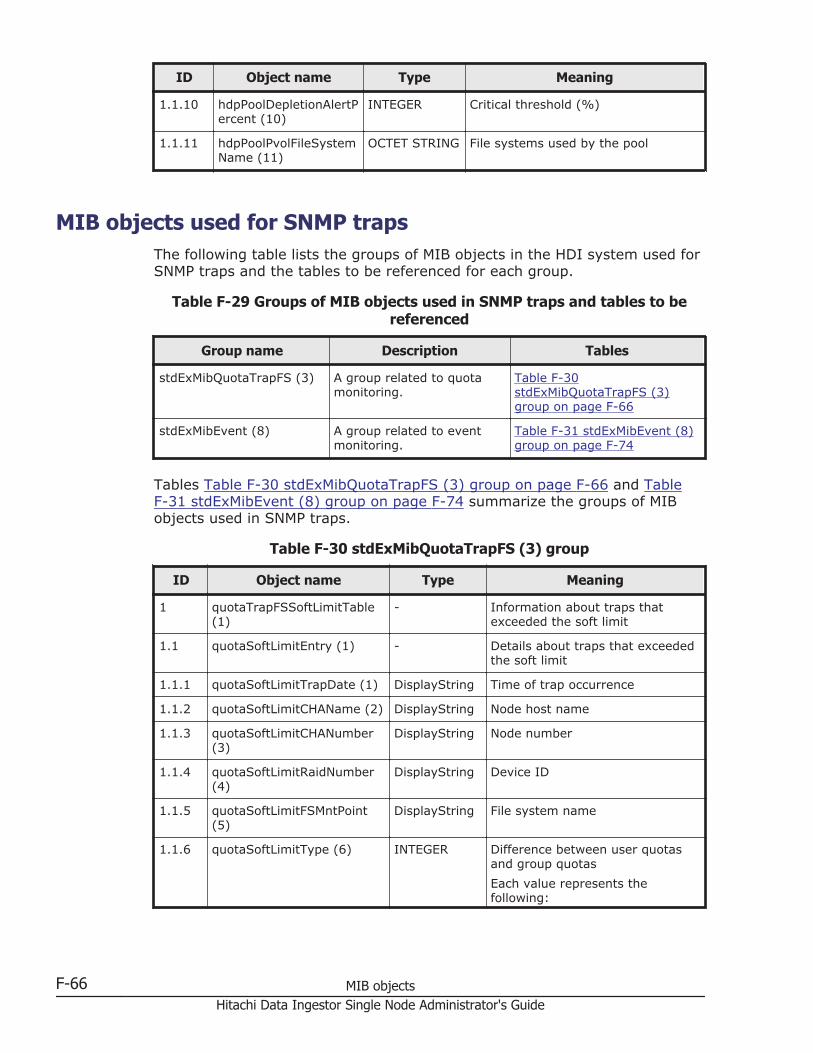
ID Object name Type Meaning
1.1.10 hdpPoolDepletionAlertPercent (10)
INTEGER Critical threshold (%)
1.1.11 hdpPoolPvolFileSystemName (11)
OCTET STRING File systems used by the pool
MIB objects used for SNMP trapsThe following table lists the groups of MIB objects in the HDI system used forSNMP traps and the tables to be referenced for each group.
Table F-29 Groups of MIB objects used in SNMP traps and tables to bereferenced
Group name Description Tables
stdExMibQuotaTrapFS (3) A group related to quotamonitoring.
Table F-30stdExMibQuotaTrapFS (3)group on page F-66
stdExMibEvent (8) A group related to eventmonitoring.
Table F-31 stdExMibEvent (8)group on page F-74
Tables Table F-30 stdExMibQuotaTrapFS (3) group on page F-66 and TableF-31 stdExMibEvent (8) group on page F-74 summarize the groups of MIBobjects used in SNMP traps.
Table F-30 stdExMibQuotaTrapFS (3) group
ID Object name Type Meaning
1 quotaTrapFSSoftLimitTable(1)
- Information about traps thatexceeded the soft limit
1.1 quotaSoftLimitEntry (1) - Details about traps that exceededthe soft limit
1.1.1 quotaSoftLimitTrapDate (1) DisplayString Time of trap occurrence
1.1.2 quotaSoftLimitCHAName (2) DisplayString Node host name
1.1.3 quotaSoftLimitCHANumber(3)
DisplayString Node number
1.1.4 quotaSoftLimitRaidNumber(4)
DisplayString Device ID
1.1.5 quotaSoftLimitFSMntPoint(5)
DisplayString File system name
1.1.6 quotaSoftLimitType (6) INTEGER Difference between user quotasand group quotas
Each value represents thefollowing:
F-66 MIB objectsHitachi Data Ingestor Single Node Administrator's Guide

ID Object name Type Meaning
1: user, 2: group
1.1.7 quotaSoftLimitName (7) DisplayString User name or group name
1.1.8 quotaSoftLimitID (8) Integer32 UID or GID
1.1.9 quotaSoftLimitClass (9) INTEGER Excess type (blocks or inodes)
Each value represents thefollowing:
1: block, 2: inode
1.1.10 quotaSoftLimitUsed (10) Counter64 Current usage (if the excess typeis blocks, the unit is KB)
1.1.11 quotaSoftLimitSoftLimitValue (11)
Counter64 Soft limit (if the excess type isblocks, the unit is KB)
1.1.12 quotaSoftLimitHardLimitValue (12)
Counter64 Hard limit (if the excess type isblocks, the unit is KB)
1.1.13 quotaSoftLimitRemainGracePeriod (13)
Counter32 Time (seconds) remaining for thegrace period
2 quotaTrapFSLimitExceeded(2)
- Information about traps thatexceeded the grace period
2.1 quotaLimitExceededEntry(1)
- Details about traps that exceededthe grace period
2.1.1 quotaLimitExceededTrapDate (1)
DisplayString Time of trap occurrence
2.1.2 quotaLimitExceededCHAName (2)
DisplayString Node host name
2.1.3 quotaLimitExceededCHANumber (3)
DisplayString Node number
2.1.4 quotaLimitExceededRaidNumber (4)
DisplayString Device ID
2.1.5 quotaLimitExceededFSMntPoint (5)
DisplayString File system name
2.1.6 quotaLimitExceededType (6) INTEGER Difference between user quotasand group quotas
Each value represents thefollowing:
1: user, 2: group
2.1.7 quotaLimitExceededName(7)
DisplayString User name or group name
2.1.8 quotaLimitExceededID (8) Integer32 UID or GID
2.1.9 quotaLimitExceededClass(9)
INTEGER Excess type (blocks or inodes)
Each value represents thefollowing:
1: block, 2: inode
MIB objects F-67Hitachi Data Ingestor Single Node Administrator's Guide

ID Object name Type Meaning
2.1.10 quotaLimitExceededUsed(10)
Counter64 Current usage (if the excess typeis blocks, the unit is KB)
2.1.11 quotaLimitExceededSoftLimitValue (11)
Counter64 Soft limit (if the excess type isblocks, the unit is KB)
2.1.12 quotaLimitExceededHardLimitValue (12)
Counter64 Hard limit (if the excess type isblocks, the unit is KB)
2.1.13 quotaLimitExceededGracePeriodValue (13)
Counter32 Set value (days) for the graceperiod
3 quotaTrapFSSummary (3) - Information in the summary trapfor quotas
3.1 quotaSummaryEntry (1) - Details in the summary trap forquotas
3.1.1 quotaSummaryTrapDate (1) DisplayString Time when trap occurred
3.1.2 quotaSummaryCHAName(2)
DisplayString Node host name
3.1.3 quotaSummaryCHANumber(3)
DisplayString Node number
3.1.4 quotaSummaryRaidNumber(4)
DisplayString Device ID
3.1.5 quotaSummaryFSMntPoint(5)
DisplayString File system name
3.1.6 quotaSummaryBlockSoftLimitExceedingUsers (6)
Integer32 Number of users who exceed theirblock soft limit
3.1.7 quotaSummaryBlockSoftLimitExceedingGroups (7)
INTEGER Number of groups that exceedtheir block soft limit
3.1.8 quotaSummaryBlockGracePeriodExpiredUsers (8)
INTEGER Number of users whose blockgrace period has expired
3.1.9 quotaSummaryBlockGracePeriodExpiredGroups (9)
INTEGER Number of groups whose blockgrace period has expired
3.1.10 quotaSummaryFileSoftLimitExceedingUsers (10)
INTEGER Number of users who exceed theirfile soft limit
3.1.11 quotaSummaryFileSoftLimitExceedingGroups (11)
INTEGER Number of groups that exceedtheir file soft limit
3.1.12 quotaSummaryFileGracePeriodExpiredUser (12)
INTEGER Number of users whose file graceperiod has expired
3.1.13 quotaSummaryFileGracePeriodExpiredGroups (13)
INTEGER Number of groups whose filegrace period has expired
4 quotaTrapFSDetailSuppress(4)
- Information in the trap for quotaswhen individual reports aresuppressed
4.1 quotaDetailSuppressEntry(1)
- Details in the trap for quotaswhen individual reports aresuppressed
F-68 MIB objectsHitachi Data Ingestor Single Node Administrator's Guide
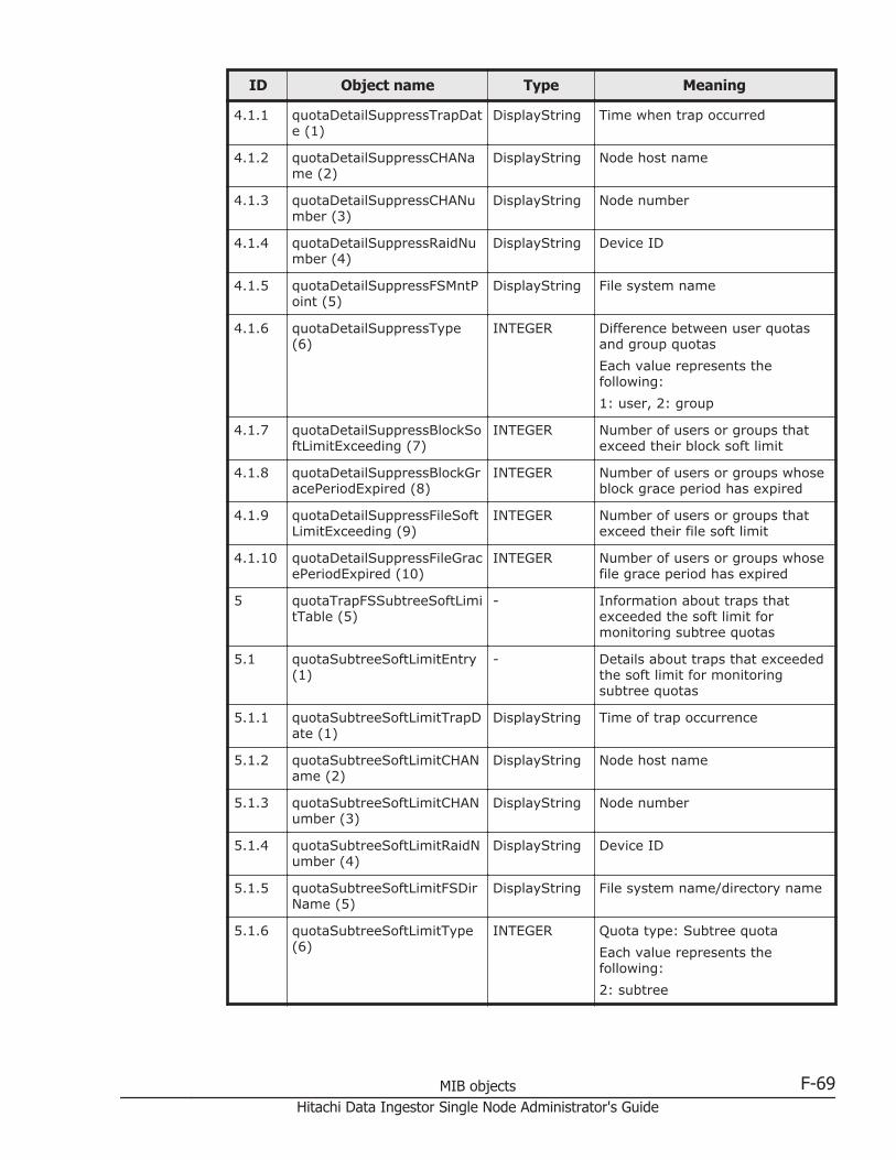
ID Object name Type Meaning
4.1.1 quotaDetailSuppressTrapDate (1)
DisplayString Time when trap occurred
4.1.2 quotaDetailSuppressCHAName (2)
DisplayString Node host name
4.1.3 quotaDetailSuppressCHANumber (3)
DisplayString Node number
4.1.4 quotaDetailSuppressRaidNumber (4)
DisplayString Device ID
4.1.5 quotaDetailSuppressFSMntPoint (5)
DisplayString File system name
4.1.6 quotaDetailSuppressType(6)
INTEGER Difference between user quotasand group quotas
Each value represents thefollowing:
1: user, 2: group
4.1.7 quotaDetailSuppressBlockSoftLimitExceeding (7)
INTEGER Number of users or groups thatexceed their block soft limit
4.1.8 quotaDetailSuppressBlockGracePeriodExpired (8)
INTEGER Number of users or groups whoseblock grace period has expired
4.1.9 quotaDetailSuppressFileSoftLimitExceeding (9)
INTEGER Number of users or groups thatexceed their file soft limit
4.1.10 quotaDetailSuppressFileGracePeriodExpired (10)
INTEGER Number of users or groups whosefile grace period has expired
5 quotaTrapFSSubtreeSoftLimitTable (5)
- Information about traps thatexceeded the soft limit formonitoring subtree quotas
5.1 quotaSubtreeSoftLimitEntry(1)
- Details about traps that exceededthe soft limit for monitoringsubtree quotas
5.1.1 quotaSubtreeSoftLimitTrapDate (1)
DisplayString Time of trap occurrence
5.1.2 quotaSubtreeSoftLimitCHAName (2)
DisplayString Node host name
5.1.3 quotaSubtreeSoftLimitCHANumber (3)
DisplayString Node number
5.1.4 quotaSubtreeSoftLimitRaidNumber (4)
DisplayString Device ID
5.1.5 quotaSubtreeSoftLimitFSDirName (5)
DisplayString File system name/directory name
5.1.6 quotaSubtreeSoftLimitType(6)
INTEGER Quota type: Subtree quota
Each value represents thefollowing:
2: subtree
MIB objects F-69Hitachi Data Ingestor Single Node Administrator's Guide

ID Object name Type Meaning
5.1.7 quotaSubtreeSoftLimitName(7)
DisplayString NULL
5.1.8 quotaSubtreeSoftLimitID (8) Integer32 -1
5.1.9 quotaSubtreeSoftLimitClass(9)
INTEGER Excess type (blocks or inodes)
Each value represents thefollowing:
1: block, 2: inode
5.1.10 quotaSubtreeSoftLimitUsed(10)
Counter64 Current usage (if the excess typeis blocks, the unit is KB)
5.1.11 quotaSubtreeSoftLimitSoftLimitValue (11)
Counter64 Soft limit (if the excess type isblocks, the unit is KB)
5.1.12 quotaSubtreeSoftLimitHardLimitValue (12)
Counter64 Hard limit (if the excess type isblocks, the unit is KB)
5.1.13 quotaSubtreeSoftLimitRemainGracePeriod (13)
Counter32 Time (seconds) remaining for thegrace period
6 quotaTrapFSSubtreeLimitExceeded (6)
- Information about traps thatexceeded the grace period formonitoring subtree quotas
6.1 quotaSubtreeLimitExceededEntry (1)
- Details about traps that exceededthe grace period for monitoringsubtree quotas
6.1.1 quotaSubtreeLimitExceededTrapDate (1)
DisplayString Time of trap occurrence
6.1.2 quotaSubtreeLimitExceededCHAName (2)
DisplayString Node host name
6.1.3 quotaSubtreeLimitExceededCHANumber (3)
DisplayString Node number
6.1.4 quotaSubtreeLimitExceededRaidNumber (4)
DisplayString Device ID
6.1.5 quotaSubtreeLimitExceededFSDirName (5)
DisplayString File system name/directory name
6.1.6 quotaSubtreeLimitExceededType (6)
INTEGER Quota type: Subtree quota
Each value represents thefollowing:
2: subtree
6.1.7 quotaSubtreeLimitExceededName (7)
DisplayString NULL
6.1.8 quotaSubtreeLimitExceededID (8)
Integer32 -1
6.1.9 quotaSubtreeLimitExceededClass (9)
INTEGER Excess type (blocks or inodes)
Each value represents thefollowing:
1: block, 2: inode
F-70 MIB objectsHitachi Data Ingestor Single Node Administrator's Guide

ID Object name Type Meaning
6.1.10 quotaSubtreeLimitExceededUsed (10)
Counter64 Current usage (if the excess typeis blocks, the unit is KB)
6.1.11 quotaSubtreeLimitExceededSoftLimitValue (11)
Counter64 Soft limit (if the excess type isblocks, the unit is KB)
6.1.12 quotaSubtreeLimitExceededHardLimitValue (12)
Counter64 Hard limit (if the excess type isblocks, the unit is KB)
6.1.13 quotaSubtreeLimitExceededGracePeriodValue (13)
Counter32 Set value (days) for the graceperiod
7 quotaTrapFSSubtreeSummary (7)
- Information in the summary trapfor subtree quotas
7.1 quotaSubtreeSummaryEntry(1)
- Details in the summary trap forsubtree quotas
7.1.1 quotaSubtreeSummaryTrapDate (1)
DisplayString Time when trap occurred
7.1.2 quotaSubtreeSummaryCHAName (2)
DisplayString Node host name
7.1.3 quotaSubtreeSummaryCHANumber (3)
DisplayString Node number
7.1.4 quotaSubtreeSummaryRaidNumber (4)
DisplayString Device ID
7.1.5 quotaSubtreeSummaryFSDirName (5)
DisplayString File system name or file systemname/directory name
7.1.6 quotaSubtreeSummaryType(6)
INTEGER Summary type: Subtree quota orsubtree user group quota
Each value represents thefollowing:
2: subtree, 5: subtree-user-group
7.1.7 quotaSubtreeSummaryBlockSoftLimitExceedingUsers (7)
INTEGER If the summary type is subtreequota, this value is -1.
If the summary type is subtreeuser group quota, this value is thenumber of users who exceed theirsoft limit for the number ofblocks.
7.1.8 quotaSubtreeSummaryBlockSoftLimitExceedingGroups(8)
INTEGER If the summary type is subtreequota, this value is -1.
If the summary type is subtreeuser group quota, this value is thenumber of groups that exceedtheir soft limit for the number ofblocks.
7.1.9 quotaSubtreeSummaryBlockSoftLimitExceedingDirectories (9)
INTEGER If the summary type is subtreequota, this value is the number ofdirectories that exceed their softlimit for the number of blocks.
MIB objects F-71Hitachi Data Ingestor Single Node Administrator's Guide

ID Object name Type Meaning
If the summary type is subtreeuser group quota, this value is -1.
7.1.10 quotaSubtreeSummaryBlockGracePeriodExpiredUsers(10)
INTEGER If the summary type is subtreequota, this value is -1.
If the summary type is subtreeuser group quota, this value is thenumber of users whose graceperiod for the number of blockshas expired.
7.1.11 quotaSubtreeSummaryBlockGracePeriodExpiredGroups(11)
INTEGER If the summary type is subtreequota, this value is -1.
If the summary type is subtreeuser group quota, this value is thenumber of groups whose graceperiod for the number of blockshas expired.
7.1.12 quotaSubtreeSummaryBlockGracePeriodExpiredDirectories (12)
INTEGER If the summary type is subtreequota, this value is the number ofdirectories whose grace period forthe number of blocks has expired.
If the summary type is subtreeuser group quota, this value is -1.
7.1.13 quotaSubtreeSummaryFileSoftLimitExceedingUsers (13)
INTEGER If the summary type is subtreequota, this value is -1.
If the summary type is subtreeuser group quota, this value is thenumber of users who exceed theirsoft limit for the number ofinodes.
7.1.14 quotaSubtreeSummaryFileSoftLimitExceedingGroups(14)
INTEGER If the summary type is subtreequota, this value is -1.
If the summary type is subtreeuser group quota, this value is thenumber of groups that exceedtheir soft limit for the number ofinodes.
7.1.15 quotaSubtreeSummaryFileSoftLimitExceedingDirectories(15)
INTEGER If the summary type is subtreequota, this value is the number ofdirectories that exceed their softlimit for the number of inodes.
If the summary type is subtreeuser group quota, this value is -1.
7.1.16 quotaSubtreeSummaryFileGracePeriodExpiredUsers (16)
INTEGER If the summary type is subtreequota, this value is -1.
If the summary type is subtreeuser group quota, this value is thenumber of users whose graceperiod for the number of inodeshas expired.
F-72 MIB objectsHitachi Data Ingestor Single Node Administrator's Guide
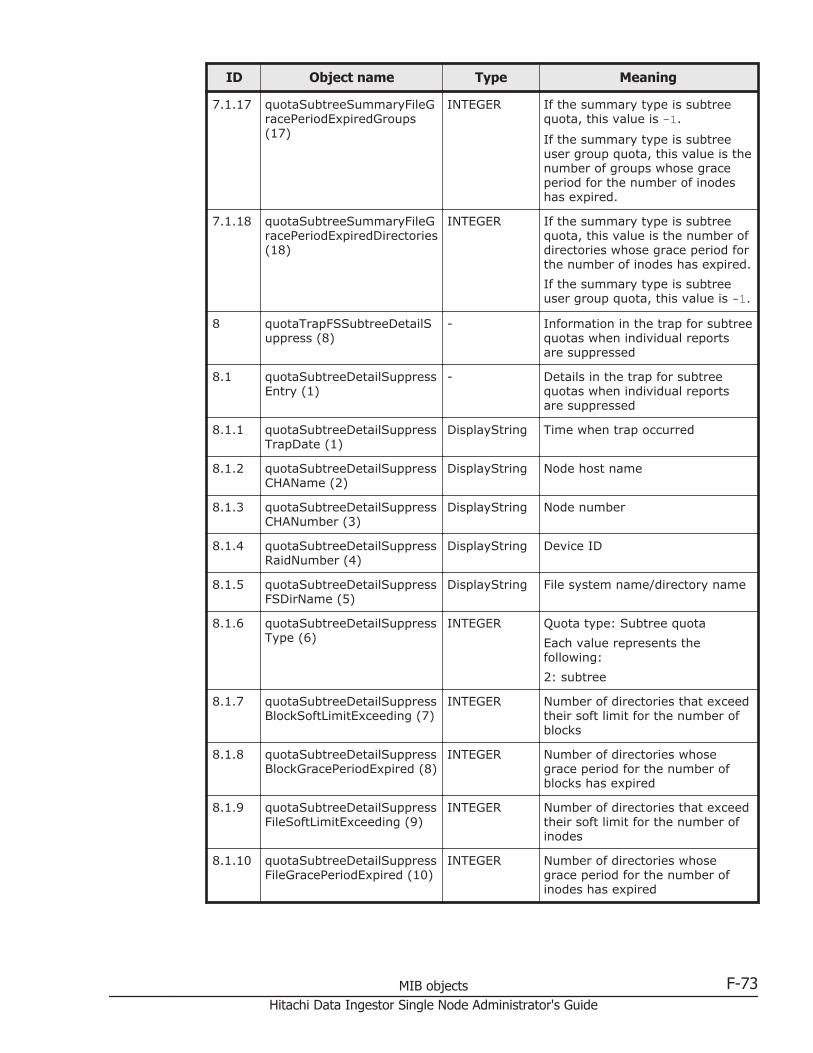
ID Object name Type Meaning
7.1.17 quotaSubtreeSummaryFileGracePeriodExpiredGroups(17)
INTEGER If the summary type is subtreequota, this value is -1.
If the summary type is subtreeuser group quota, this value is thenumber of groups whose graceperiod for the number of inodeshas expired.
7.1.18 quotaSubtreeSummaryFileGracePeriodExpiredDirectories(18)
INTEGER If the summary type is subtreequota, this value is the number ofdirectories whose grace period forthe number of inodes has expired.
If the summary type is subtreeuser group quota, this value is -1.
8 quotaTrapFSSubtreeDetailSuppress (8)
- Information in the trap for subtreequotas when individual reportsare suppressed
8.1 quotaSubtreeDetailSuppressEntry (1)
- Details in the trap for subtreequotas when individual reportsare suppressed
8.1.1 quotaSubtreeDetailSuppressTrapDate (1)
DisplayString Time when trap occurred
8.1.2 quotaSubtreeDetailSuppressCHAName (2)
DisplayString Node host name
8.1.3 quotaSubtreeDetailSuppressCHANumber (3)
DisplayString Node number
8.1.4 quotaSubtreeDetailSuppressRaidNumber (4)
DisplayString Device ID
8.1.5 quotaSubtreeDetailSuppressFSDirName (5)
DisplayString File system name/directory name
8.1.6 quotaSubtreeDetailSuppressType (6)
INTEGER Quota type: Subtree quota
Each value represents thefollowing:
2: subtree
8.1.7 quotaSubtreeDetailSuppressBlockSoftLimitExceeding (7)
INTEGER Number of directories that exceedtheir soft limit for the number ofblocks
8.1.8 quotaSubtreeDetailSuppressBlockGracePeriodExpired (8)
INTEGER Number of directories whosegrace period for the number ofblocks has expired
8.1.9 quotaSubtreeDetailSuppressFileSoftLimitExceeding (9)
INTEGER Number of directories that exceedtheir soft limit for the number ofinodes
8.1.10 quotaSubtreeDetailSuppressFileGracePeriodExpired (10)
INTEGER Number of directories whosegrace period for the number ofinodes has expired
MIB objects F-73Hitachi Data Ingestor Single Node Administrator's Guide
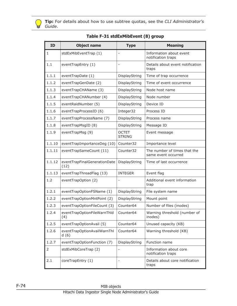
Tip: For details about how to use subtree quotas, see the CLI Administrator'sGuide.
Table F-31 stdExMibEvent (8) group
ID Object name Type Meaning
1 stdExMibEventTrap (1) - Information about eventnotification traps
1.1 eventTrapEntry (1) - Details about event notificationtraps
1.1.1 eventTrapDate (1) DisplayString Time of trap occurrence
1.1.2 eventTrapGenDate (2) DisplayString Time of event occurrence
1.1.3 eventTrapCHAName (3) DisplayString Node host name
1.1.4 eventTrapCHANumber (4) DisplayString Node number
1.1.5 eventRaidNumber (5) DisplayString Device ID
1.1.6 eventTrapProcessID (6) Integer32 Process ID
1.1.7 eventTrapProcessName (7) DisplayString Process name
1.1.8 eventTrapMsgID (8) DisplayString Message ID
1.1.9 eventTrapMsg (9) OCTETSTRING
Event message
1.1.10 eventTrapImportanceDeg (10) Counter32 Importance level
1.1.11 eventTrapSameCount (11) Counter32 The number of times that thesame event occurred
1.1.12 eventTrapFinalGenerationDate(12)
DisplayString Time of last occurrence
1.1.13 eventTrapThreadFlag (13) INTEGER Event flag
1.2 eventTrapOption (2) - Additional event informationtrap
1.2.1 eventTrapOptionFSName (1) DisplayString File system name
1.2.2 eventTrapOptionMntPoint (2) DisplayString Mount point
1.2.3 eventTrapOptionFileCount (3) Counter64 Number of files (inodes)
1.2.4 eventTrapOptionFileWarnThld(4)
Counter64 Warning threshold (number ofinodes)
1.2.5 eventTrapOptionAvail (5) Counter64 Unused capacity (KB)
1.2.6 eventTrapOptionAvailWarnThld (6)
Counter64 Warning threshold (KB)
1.2.7 eventTrapOptionFunction (7) DisplayString Function name
2 stdExMibCoreTrap (2) - Information about corenotification traps
2.1 coreTrapEntry (1) - Details about core notificationtraps
F-74 MIB objectsHitachi Data Ingestor Single Node Administrator's Guide
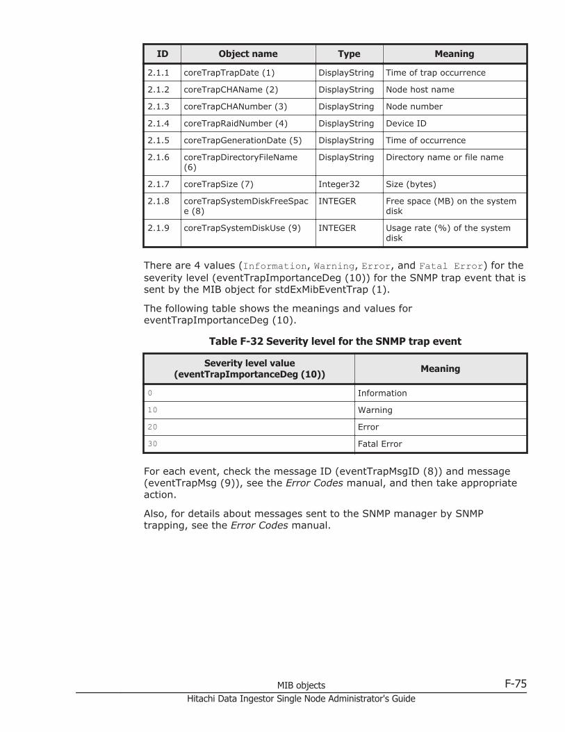
ID Object name Type Meaning
2.1.1 coreTrapTrapDate (1) DisplayString Time of trap occurrence
2.1.2 coreTrapCHAName (2) DisplayString Node host name
2.1.3 coreTrapCHANumber (3) DisplayString Node number
2.1.4 coreTrapRaidNumber (4) DisplayString Device ID
2.1.5 coreTrapGenerationDate (5) DisplayString Time of occurrence
2.1.6 coreTrapDirectoryFileName(6)
DisplayString Directory name or file name
2.1.7 coreTrapSize (7) Integer32 Size (bytes)
2.1.8 coreTrapSystemDiskFreeSpace (8)
INTEGER Free space (MB) on the systemdisk
2.1.9 coreTrapSystemDiskUse (9) INTEGER Usage rate (%) of the systemdisk
There are 4 values (Information, Warning, Error, and Fatal Error) for theseverity level (eventTrapImportanceDeg (10)) for the SNMP trap event that issent by the MIB object for stdExMibEventTrap (1).
The following table shows the meanings and values foreventTrapImportanceDeg (10).
Table F-32 Severity level for the SNMP trap event
Severity level value(eventTrapImportanceDeg (10)) Meaning
0 Information
10 Warning
20 Error
30 Fatal Error
For each event, check the message ID (eventTrapMsgID (8)) and message(eventTrapMsg (9)), see the Error Codes manual, and then take appropriateaction.
Also, for details about messages sent to the SNMP manager by SNMPtrapping, see the Error Codes manual.
MIB objects F-75Hitachi Data Ingestor Single Node Administrator's Guide

F-76 MIB objectsHitachi Data Ingestor Single Node Administrator's Guide

GOperation reference information
This appendix explains reference information for running HDI systemsconsisting of a single node.
□ List of reference information
Operation reference information G-1Hitachi Data Ingestor Single Node Administrator's Guide
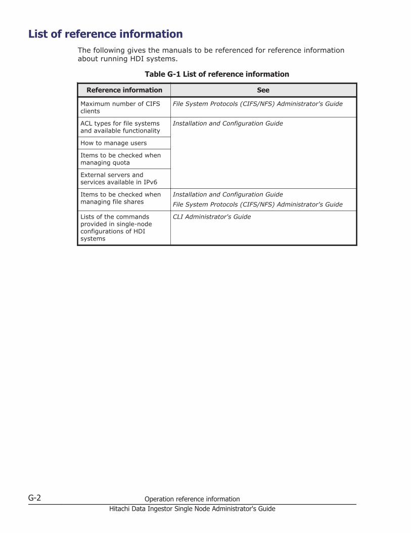
List of reference informationThe following gives the manuals to be referenced for reference informationabout running HDI systems.
Table G-1 List of reference information
Reference information See
Maximum number of CIFSclients
File System Protocols (CIFS/NFS) Administrator's Guide
ACL types for file systemsand available functionality
Installation and Configuration Guide
How to manage users
Items to be checked whenmanaging quota
External servers andservices available in IPv6
Items to be checked whenmanaging file shares
Installation and Configuration Guide
File System Protocols (CIFS/NFS) Administrator's Guide
Lists of the commandsprovided in single-nodeconfigurations of HDIsystems
CLI Administrator's Guide
G-2 Operation reference informationHitachi Data Ingestor Single Node Administrator's Guide

HNode maintenance
This appendix describes the maintenance that the system administrator mustsometimes perform for an HDI system in a single-node configuration.
□ Starting and forcibly stopping a node OS
□ Replacing the internal RAID battery
□ Managing the RAID card
Node maintenance H-1Hitachi Data Ingestor Single Node Administrator's Guide

Starting and forcibly stopping a node OSThis section explains how to control the node power for maintenance, bystarting or forcibly stopping the OS.
Starting an OSYou can start an OS by using the power switch or power button to turn on thenode.
To start the OS by turning on the power to a node:
1. Make sure that the external servers connected to the node are running.
2. Make sure that the power lamp or power indicator located on the front ofthe node is off.
3. If you use a storage system connected to the HDI system, make sure thatthe storage system and FC switch are running.If you start the OS while the storage system and FC switch are notrunning, an error will occur on the FC path.
4. If you are using encryption, when you save system settings on the HCPsystem, confirm that the HCP system is running normally, and that theHDI and HCP systems can communicate normally.User data cannot be available unless the HCP system can becommunicated with.
5. Press the power switch or power button located on the front of the node.
6. Make sure that the power lamp or power indicator lights up.
Forcibly Stopping an OSNormally, the CLI is used to stop the OS. However, if the power lamp orpower indicator cannot be turned off via commands, you can shutdown thenode to forcibly stop the OS. Follow the maintenance personnel's instructionswhen you shutdown the node.
To forcibly stop the OS by turning off the power to a node:
1. Hold down the power switch or power button located on the front of thenode for 5 seconds or more.
2. Make sure that the power lamp or power indicator is off.
Replacing the internal RAID batteryNote: For models that do not use the internal RAID battery, this replacementoperation is unnecessary.
The battery backup unit (BBU) for the RAID card is called the internal RAIDbattery. Because the internal RAID battery is expendable, we recommendthat you replace the internal RAID battery once a year. Replacement partsare subject to fees. For details about how to replace the internal RAIDbattery, see documentation provided with the device.
H-2 Node maintenanceHitachi Data Ingestor Single Node Administrator's Guide
If the internal RAID battery causes an error or becomes low on power, anevent is both sent out via an SNMP trap or email and output to the log file.The system administrator must take action according to output messages(KAQG46509-I, KAQG46510-W).
Managing the RAID cardNote: For models that do not use the internal RAID battery, this managementoperation is unnecessary.
By using the cachedbadbbuset command, the system administrator canchange the writing mode of the RAID card cache which is set when theinternal RAID battery becomes low on power.
By default, when the internal RAID battery becomes low on power, the writemode of the RAID card cache is changed from Write Back to Write Through,and then the system performance decreases to protect data.
If you change the default setting so that Write Back mode is set even if thebattery becomes low on power, the data that is not written into the internalhard disk might be lost when an error occurs, but Write Back mode canplace priority on the system performance. You can check the specified writemode by using the cachedbadbbuget command.
Also, the internal RAID battery adjusts itself regularly by charging anddischarging itself. The system administrator can use the bbuschlsetcommand to set the date and time to charge and discharge the internal RAIDbattery. Review the settings for the write mode of the RAID card cache asnecessary because the charge and discharge causes the battery power levelto drop temporarily, which the system sees as the battery being low onpower. The total time required for charge and discharge is about 12 hours.The operation time depends on the status of the internal RAID battery.
Node maintenance H-3Hitachi Data Ingestor Single Node Administrator's Guide

H-4 Node maintenanceHitachi Data Ingestor Single Node Administrator's Guide
ITerminology used in messages and
related documents
This appendix describes the differences in terminology to be aware of whenviewing the messages output by HDI and related documents.
□ Viewing messages and related documents
Terminology used in messages and related documents I-1Hitachi Data Ingestor Single Node Administrator's Guide

Viewing messages and related documentsThe messages output by HDI and some of the related documents are used forboth HDI cluster configurations and single-node configurations. As such,terms used in the messages and documents might differ from the terms usedfor HDI single-node configurations, and functionality not used by HDI systemsin single-node configurations might be listed in the messages and documents.
• When reading messages, replace the following terminology with thecorresponding terminology used in single-node configurations of HDIsystems.
Table I-1 Replacing the terminology used in cluster configurations ofHDI systems
Terminology in messages Terminology used in single-nodeconfigurations
Device file LUs in the internal hard disk or storagesystem
Fixed IP address IP address
System LU System disk
User LU User disk
• In explanations that refer to clusters, nodes, and resource groups, onlythe explanations pertaining to resource groups apply.
• Ignore any explanations regarding virtual IP addresses, heartbeat ports,failovers, and failbacks, because these terms are not used in single-nodeHDI systems.
• Cluster management LU refers to the drive capacity that has beenallocated to store system settings information.
I-2 Terminology used in messages and related documentsHitachi Data Ingestor Single Node Administrator's Guide
JAcronyms
This appendix lists the acronyms used in the HDI manuals.
□ Acronyms used in the HDI manuals
Acronyms J-1Hitachi Data Ingestor Single Node Administrator's Guide

Acronyms used in the HDI manualsThe following acronyms are used in the HDI manuals.
ABE Access Based Enumeration
ACE access control entry
ACL access control list
AES Advanced Encryption Standard
AJP Apache JServ Protocol
API application programming interface
ARP Address Resolution Protocol
ASCII American Standard Code for Information Interchange
ASN Abstract Syntax Notation
BDC Backup Domain Controller
BMC baseboard management controller
CA certificate authority
CHA channel adapter
CHAP Challenge-Handshake Authentication Protocol
CIFS Common Internet File System
CIM Common Information Model
CLI command line interface
CPU central processing unit
CSR certificate signing request
CSV comma-separated values
CTL controller
CU control unit
CV custom volume
DACL discretionary access control list
DAR Direct Access Recovery
DB database
DBMS database management system
DC domain controller
DDNS Dynamic Domain Name System
DEP data execution prevention
DES Data Encryption Standard
DFS distributed file system
DHCP Dynamic Host Configuration Protocol
J-2 AcronymsHitachi Data Ingestor Single Node Administrator's Guide
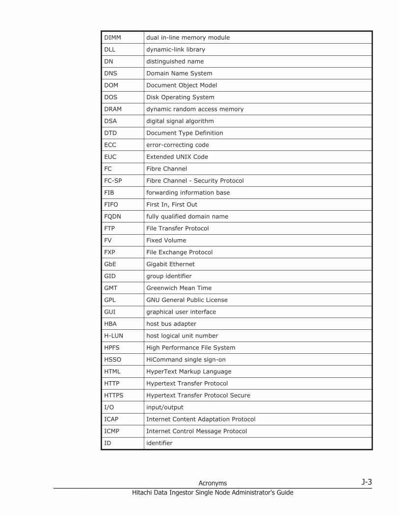
DIMM dual in-line memory module
DLL dynamic-link library
DN distinguished name
DNS Domain Name System
DOM Document Object Model
DOS Disk Operating System
DRAM dynamic random access memory
DSA digital signal algorithm
DTD Document Type Definition
ECC error-correcting code
EUC Extended UNIX Code
FC Fibre Channel
FC-SP Fibre Channel - Security Protocol
FIB forwarding information base
FIFO First In, First Out
FQDN fully qualified domain name
FTP File Transfer Protocol
FV Fixed Volume
FXP File Exchange Protocol
GbE Gigabit Ethernet
GID group identifier
GMT Greenwich Mean Time
GPL GNU General Public License
GUI graphical user interface
HBA host bus adapter
H-LUN host logical unit number
HPFS High Performance File System
HSSO HiCommand single sign-on
HTML HyperText Markup Language
HTTP Hypertext Transfer Protocol
HTTPS Hypertext Transfer Protocol Secure
I/O input/output
ICAP Internet Content Adaptation Protocol
ICMP Internet Control Message Protocol
ID identifier
Acronyms J-3Hitachi Data Ingestor Single Node Administrator's Guide
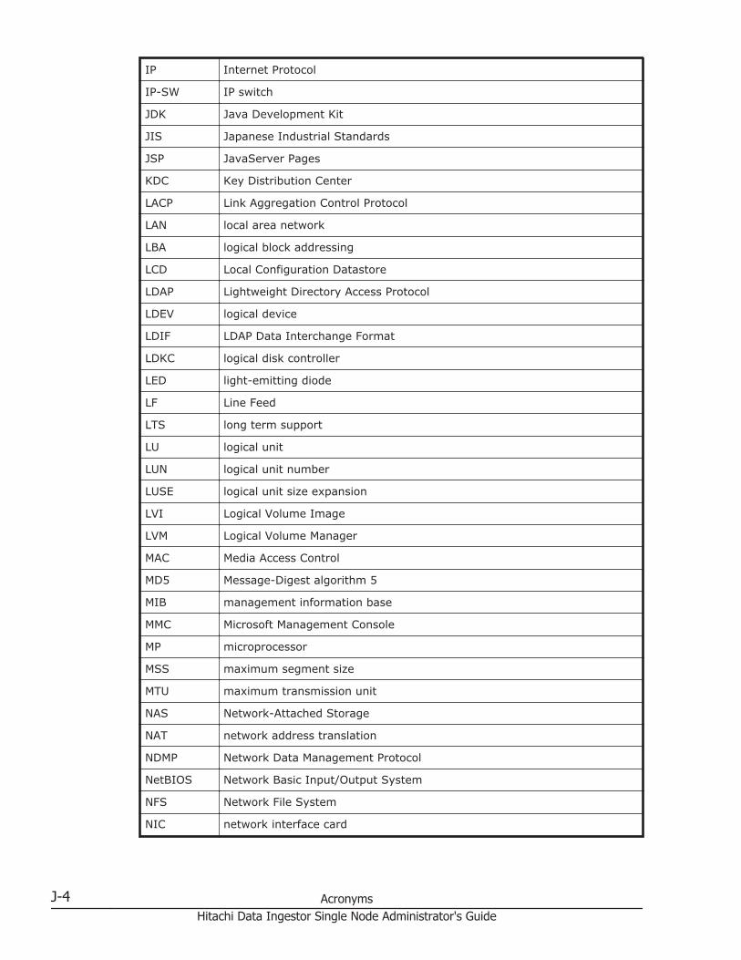
IP Internet Protocol
IP-SW IP switch
JDK Java Development Kit
JIS Japanese Industrial Standards
JSP JavaServer Pages
KDC Key Distribution Center
LACP Link Aggregation Control Protocol
LAN local area network
LBA logical block addressing
LCD Local Configuration Datastore
LDAP Lightweight Directory Access Protocol
LDEV logical device
LDIF LDAP Data Interchange Format
LDKC logical disk controller
LED light-emitting diode
LF Line Feed
LTS long term support
LU logical unit
LUN logical unit number
LUSE logical unit size expansion
LVI Logical Volume Image
LVM Logical Volume Manager
MAC Media Access Control
MD5 Message-Digest algorithm 5
MIB management information base
MMC Microsoft Management Console
MP microprocessor
MSS maximum segment size
MTU maximum transmission unit
NAS Network-Attached Storage
NAT network address translation
NDMP Network Data Management Protocol
NetBIOS Network Basic Input/Output System
NFS Network File System
NIC network interface card
J-4 AcronymsHitachi Data Ingestor Single Node Administrator's Guide
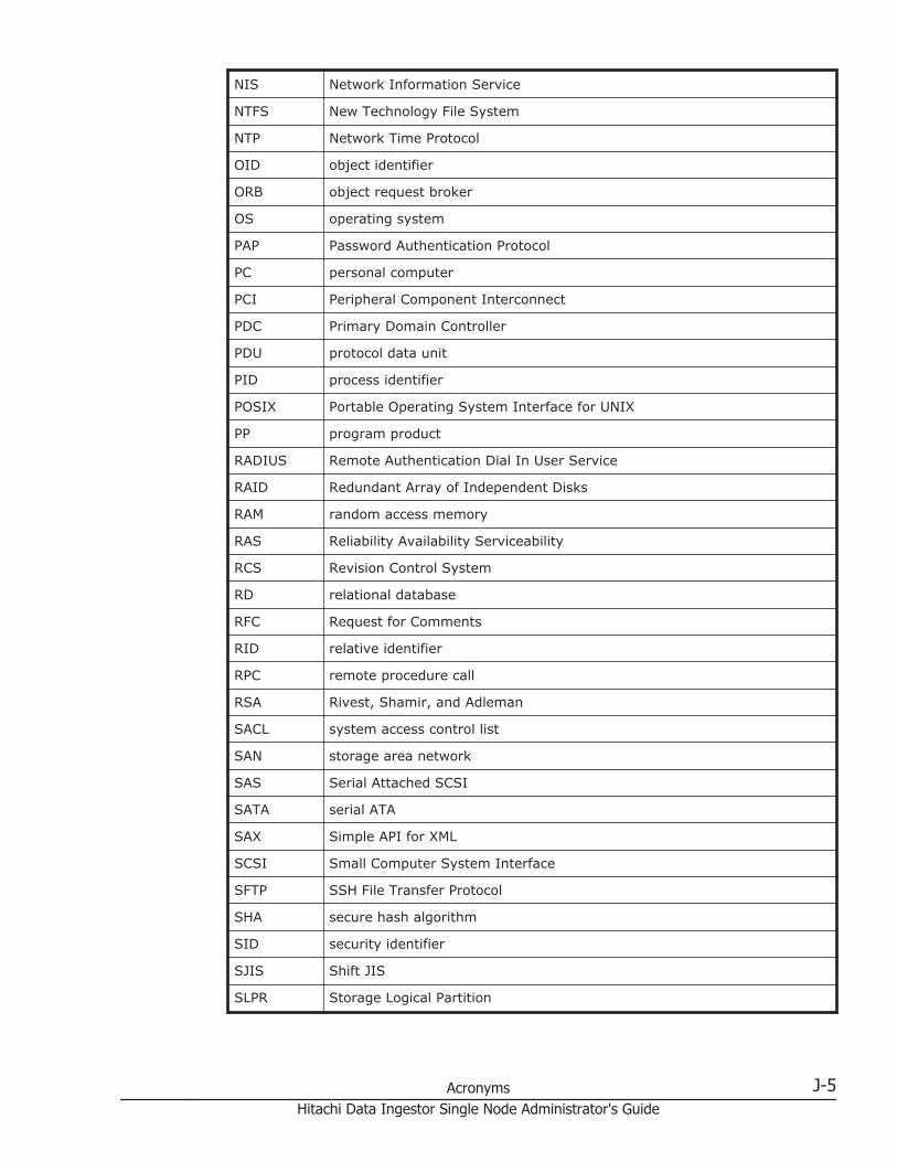
NIS Network Information Service
NTFS New Technology File System
NTP Network Time Protocol
OID object identifier
ORB object request broker
OS operating system
PAP Password Authentication Protocol
PC personal computer
PCI Peripheral Component Interconnect
PDC Primary Domain Controller
PDU protocol data unit
PID process identifier
POSIX Portable Operating System Interface for UNIX
PP program product
RADIUS Remote Authentication Dial In User Service
RAID Redundant Array of Independent Disks
RAM random access memory
RAS Reliability Availability Serviceability
RCS Revision Control System
RD relational database
RFC Request for Comments
RID relative identifier
RPC remote procedure call
RSA Rivest, Shamir, and Adleman
SACL system access control list
SAN storage area network
SAS Serial Attached SCSI
SATA serial ATA
SAX Simple API for XML
SCSI Small Computer System Interface
SFTP SSH File Transfer Protocol
SHA secure hash algorithm
SID security identifier
SJIS Shift JIS
SLPR Storage Logical Partition
Acronyms J-5Hitachi Data Ingestor Single Node Administrator's Guide

SMB Server Message Block
SMD5 Salted Message Digest 5
SMTP Simple Mail Transfer Protocol
SNMP Simple Network Management Protocol
SOAP Simple Object Access Protocol
SP service pack
SSD solid-state drive
SSH Secure Shell
SSHA Salted Secure Hash Algorithm
SSL Secure Sockets Layer
SSO single sign-on
SVGA Super Video Graphics Array
TCP Transmission Control Protocol
TFTP Trivial File Transfer Protocol
TLS Transport Layer Security
TOS type of service
TTL time to live
UAC User Account Control
UDP User Datagram Protocol
UID user identifier
UNC Universal Naming Convention
UPnP Universal Plug and Play
URI Uniform Resource Identifier
URL Uniform Resource Locator
UTC Coordinated Universal Time
UTF UCS Transformation Format
VDEV Virtual Device
VLAN virtual LAN
VLL Virtual LVI/LUN
WADL Web Application Description Language
WAN wide area network
WINS Windows Internet Name Service
WORM Write Once, Read Many
WS workstation
WWN World Wide Name
J-6 AcronymsHitachi Data Ingestor Single Node Administrator's Guide

WWW World Wide Web
XDR External Data Representation
XFS extended file system
XML Extensible Markup Language
Acronyms J-7Hitachi Data Ingestor Single Node Administrator's Guide

J-8 AcronymsHitachi Data Ingestor Single Node Administrator's Guide
Glossary
This glossary explains the terms used in this manual.
A
ACEAn entry in an ACL. An ACE sets access permissions for directories and files for eachuser and group. ACE formats differ depending on the ACL type.
ACLA list of all the ACEs for a particular directory or file. An ACL defines the accesspermissions for a particular directory or file.
ACL typeThe type of file system or file that is supported by the ACL. The ACL types that can beused in HDI systems are the Advanced ACL type (compatible with NTFS ACL), and theClassic ACL type (compatible with POSIX ACL).
Anti-Virus EnablerA program used to scan, in real time, for viruses in data shared with users via CIFS inan HDI system.
B
Backup RestoreA program used for backing up data in an HDI file system.
# A B C D E F G H I J K L M N O P Q R S T U V W X Y Z
Glossary-1Hitachi Data Ingestor Single Node Administrator's Guide
C
CIFSA protocol that provides file-sharing services to Windows users.
D
Data ControlOne of the programs on a node OS.
Dynamic ProvisioningA function that virtually allocates volumes of a given capacity to a host independent ofthe physical capacity of the storage system.
Dynamic TieringThis storage system functionality automatically reallocates data based on I/O load.
F
File SharingOne of the programs on a node OS.
front-end LANA LAN used by a client to access data stored in an HDI system.
M
maintenance personnelHitachi engineers who maintain HDI systems.
management consoleA computer used by the system administrator to operate HDI.
N
NFSA protocol that provides file-sharing services to UNIX users.
# A B C D E F G H I J K L M N O P Q R S T U V W X Y Z
Glossary-2Hitachi Data Ingestor Single Node Administrator's Guide

O
OS diskA logical disk area in a node, that stores the OS and programs that run on the OS.
P
Primary Server BaseA program that provides Web server functionality.
Q
quotaThe maximum block space and maximum number of inodes available to a user. In anHDI system, quotas can be set and managed for each file system and directory.
R
resource groupA management unit used to manage multiple resources (such as NFS share settings,CIFS share settings, file system information, and IP address information) as a group.
S
system administratorA user who manages an HDI system. The system administrator sets up an HDI systemand monitors system operations and error information.
system diskA disk in a node that contains HDI system settings and programs that run on the node.
T
trunkingA technology used to create a virtual network interface from a group of ports. In an HDIsystem, you can create a network that comprises virtual network interfaces that werecreated by using this technology.
# A B C D E F G H I J K L M N O P Q R S T U V W X Y Z
Glossary-3Hitachi Data Ingestor Single Node Administrator's Guide
U
user diskThe user disk is made up of volume groups.
user mappingThe process of assigning a user ID and group ID to a user registered in a domaincontroller when the user accesses a CIFS share.
V
volume groupA volume group is used to manage disk areas in internal hard disks or storage systemswhere user data is stored. A specific part of the capacity of a volume group is allocatedto a file system.
W
WORMAn abbreviation for "Write Once, Read Many". The WORM status indicates that datacannot be modified. A file whose status is changed to the WORM status is called aWORM file, and a file system in which any files can be changed to a WORM file is calleda WORM file system.
# A B C D E F G H I J K L M N O P Q R S T U V W X Y Z
Glossary-4Hitachi Data Ingestor Single Node Administrator's Guide
Index
A
accessCIFS client logs 4-10setting up environment for CIFS client 4-2setting up environment for NFS client 4-11
accountchanging password 2-2
Active Directoryjoining domain 4-2rejoining domain 4-5
addingrouting information 9-4
application area B-4automatic account lockout settings
changing (system administrator) 2-2
B
backing upsystem configuration regularly 8-2system configuration, manually 8-2tape device 7-2
C
cache residency 3-4changing
account password 2-2disk use 6-4negotiation mode 9-5node host name 9-3node IP address 9-2policy for migrating data to HCP 3-4
schedule for migrating data to HCP 3-4command
setting up environment 11-2configuring
workgroup 4-7creating
shared directory 3-2
D
datashowing migrated to HCP 5-2
deletingrouting information 9-4volume group 6-4volume group LUs 6-4
diskschanging use 6-4
E
end userGUI operation D-1
error email notifications 10-6expanding capacity
file systems 3-5expansion
increasing the number of disks 6-2
F
file serverimportation from 3-6
Index-1Hitachi Data Ingestor Single Node Administrator's Guide
file systemsexpanding capacity 3-5
G
global tab area B-3global taskbar area B-2groups of MIB objects F-3GUI
basic operations B-1notes on using B-5operation by end user D-1operations A-1reference C-1window configurations B-2
H
HCPchanging migration policy 3-4changing migration schedule 3-4sharing migrated data as read-only 3-3showing previous data 5-2
host namechanging for node 9-3
I
identifyingusers by user mapping 4-8
importationfile server 3-6
increasingnumber of disks 6-2
IP addresschanging for node 9-2
J
joiningActive Directory domain 4-2NT domain 4-5
L
link aggregation 9-7link alternation 9-8
performing manually 9-9logging on 1-2LUs
deleting from volume groups 6-4
M
maintenancenode H-1
MIB object F-1responding to SNMP get request F-3used for SNMP trap F-66
migrationchanging policy 3-4changing schedule 3-4
N
navigation area B-3negotiation mode
changing 9-5node
maintenance H-1NT domain
joining 4-5number of disks
increasing 6-2
O
OSforcibly stopping H-2starting H-2
P
password policychanging (system administrator) 2-2
policychanging for migrating data to HCP 3-4
power indicator H-2power lamp H-2
R
rejoiningActive Directory domain 4-5
Index-2Hitachi Data Ingestor Single Node Administrator's Guide

reserved words E-1restoring
tape device 7-4RID 4-8routing information
adding 9-4deleting 9-4
S
schedulechanging for migrating data to HCP 3-4
session timeoutchanging (system administrator) 2-2
settingconditions for preventing files from turning intostub files 3-4link aggregation 9-7link alternation 9-8
setting upaccess environment from CIFS client 4-2access environment from NFS client 4-11environment for command 11-2link configuration 9-7public key certificate 11-2virus scanning 7-2VLAN 9-9
shared directorycreating 3-2
sharing (read-only)data migrated to HCP systems 3-3
showingprevious data migrated to HCP 5-2
SNMPv2using 10-2
SNMPv3using 10-3
softwareupdating 12-2
structure for standard MIB objects F-2stub files
setting exceptions 3-4system administrator
automatic account lockout settings 2-2password policy 2-2session timeout 2-2
system configurationbacking up manually 8-2
backing up regularly 8-2
T
tape devicebacking up data 7-2restoring data 7-4
U
updatingsoftware 12-2using installation file registered in HCP system12-2using installation media 12-3
user mapping 4-8using
SNMPv2 10-2SNMPv3 10-3
V
virus scanning setup 7-2VLAN ID 9-9VLAN setup 9-9volume group
deleting 6-4
W
workgroupconfiguring 4-7
Index-3Hitachi Data Ingestor Single Node Administrator's Guide

Index-4Hitachi Data Ingestor Single Node Administrator's Guide

Hitachi Data Ingestor Single Node Administrator's Guide
Hitachi Data Systems
Corporate Headquarters2845 Lafayette StreetSanta Clara, California 95050-2639U.S.A.www.hds.com
Regional Contact Information
Americas+1 408 970 [email protected]
Europe, Middle East, and Africa+44 (0)1753 [email protected]
Asia Pacific+852 3189 [email protected]
MK-90HDI039-10


