SISQUAI: A SIMPLIFIED METHOD FOR SEISMIC ASSESSMENT OF REGULAR HARBOR WHARVES STRUCTURES Denis DAVI 1 ABSTRACT Since the evolution of the French national seismic zoning in October 2010, most of harbor facilities of the French territory are now located in recognized seismic zones. However, no specific seismic codes have yet been published in France to cover harbor wharves particular type of structures. The SisQuai method was thus developed by Cerema in order to give a first preliminary evaluation of the seismic resisting capacity of most regular wharves structures, consisting in piles supported concrete slab equipped with rear passive steel studs anchoring. This method, which is mainly based on fundamental mode spectral analysis approach inspired from Eurocode 8-2 rigid deck model, also accounts from torsional effects as well as kinematic effects from soil deformation around piles and Mononobe-Okabe dynamic soil pressure against retaining back- wall. It results in an estimation of the risk of failure of the main structural elements of the wharf unit (flexural or shear failure of piles, tensile failure of steel anchorage). The aim is, from a relatively limited number of entrance parameters, to provide a fast preliminary evaluation of the seismic vulnerability of this particular type of structures, thus enabling to treat a large number of units and identify those that require more specific investigations or more detailed numerical analysis. Comparisons of SisQuai results with 3D finite elements multi-modal dynamic analysis for different structure configurations and context tend to demonstrate a 35% precision range, which is considered satisfactory at this stage with regard to preliminary evaluation objectives. Keywords: Harbor wharves; Vulnerability assessment; Simplified preliminary evaluation 1. INTRODUCTION Harbor facilities represent major strategical economical equipment since they ensure a great part of international goods transportation in most countries with maritime border. Moreover they can be devoted to play a fundamental role in case a seismic crises for regional rescue and emergency planning, especially on island territories: supply of food, first-aid and medicines, emergency housing materials, etc. However, contrary to buildings or bridges that are explicitly covered by the new French seismic national regulation (MEEDDM. 2010) (MEDDTL. 2011) (METL. 2012) which imposes Eurocode 8 (CEN/TC250. 2004) (CEN/TC250. 2005) (CEN/TC250. 2006) for seismic design of those structures, no specific seismic code as yet been published in France to cover the case of harbor wharves structures. Moreover the recent evolution of the French national seismic zoning defined by decree n° 2010-1255 on 22 nd October 2010, revised in January 2015 (MEDDE. 2015) now locates most of French harbor facilities in recognized seismic zones (generally ranged from low to moderate seismicity with an exception for the Caribbean Islands which are defined as strong seismicity areas) as shown in Figure 1. Among the different types of wharf structures, piles supported concrete slab equipped with rear passive steel studs anchoring (Figure 2) are by far the most widely used in France. 1 Cerema, Direction Méditerranée, 30 avenue Albert Einstein, F-13593, Aix-en-Provence, France, [email protected]
Transcript
SISQUAI: A SIMPLIFIED METHOD FOR SEISMIC ASSESSMENT OF REGULAR HARBOR WHARVES STRUCTURES
Denis DAVI1
ABSTRACT Since the evolution of the French national seismic zoning in October 2010, most of harbor facilities of the French territory are now located in recognized seismic zones. However, no specific seismic codes have yet been published in France to cover harbor wharves particular type of structures. The SisQuai method was thus developed by Cerema in order to give a first preliminary evaluation of the seismic resisting capacity of most regular wharves structures, consisting in piles supported concrete slab equipped with rear passive steel studs anchoring. This method, which is mainly based on fundamental mode spectral analysis approach inspired from Eurocode 8-2 rigid deck model, also accounts from torsional effects as well as kinematic effects from soil deformation around piles and Mononobe-Okabe dynamic soil pressure against retaining back-wall. It results in an estimation of the risk of failure of the main structural elements of the wharf unit (flexural or shear failure of piles, tensile failure of steel anchorage). The aim is, from a relatively limited number of entrance parameters, to provide a fast preliminary evaluation of the seismic vulnerability of this particular type of structures, thus enabling to treat a large number of units and identify those that require more specific investigations or more detailed numerical analysis. Comparisons of SisQuai results with 3D finite elements multi-modal dynamic analysis for different structure configurations and context tend to demonstrate a 35% precision range, which is considered satisfactory at this stage with regard to preliminary evaluation objectives. Keywords: Harbor wharves; Vulnerability assessment; Simplified preliminary evaluation 1. INTRODUCTION Harbor facilities represent major strategical economical equipment since they ensure a great part of international goods transportation in most countries with maritime border. Moreover they can be devoted to play a fundamental role in case a seismic crises for regional rescue and emergency planning, especially on island territories: supply of food, first-aid and medicines, emergency housing materials, etc. However, contrary to buildings or bridges that are explicitly covered by the new French seismic national regulation (MEEDDM. 2010) (MEDDTL. 2011) (METL. 2012) which imposes Eurocode 8 (CEN/TC250. 2004) (CEN/TC250. 2005) (CEN/TC250. 2006) for seismic design of those structures, no specific seismic code as yet been published in France to cover the case of harbor wharves structures. Moreover the recent evolution of the French national seismic zoning defined by decree n° 2010-1255 on 22nd October 2010, revised in January 2015 (MEDDE. 2015) now locates most of French harbor facilities in recognized seismic zones (generally ranged from low to moderate seismicity with an exception for the Caribbean Islands which are defined as strong seismicity areas) as shown in Figure 1. Among the different types of wharf structures, piles supported concrete slab equipped with rear passive steel studs anchoring (Figure 2) are by far the most widely used in France.
1Cerema, Direction Méditerranée, 30 avenue Albert Einstein, F-13593, Aix-en-Provence, France,
Figure 1. New French national seismic zoning from October 2010, revised in January 2015 (MEDDE. 2015) and location of main harbor facilities (MEDDE. 2012)
Figure 2. Schematic representation of the main resisting components of the type of wharf structures under study:
piles, rear passive steel studs anchoring and the retaining back wall 2. DESCRIPTION OF THE SISQUAI METHOD 2.1 General principles In order to give a first preliminary evaluation of the seismic resisting capacity of most regular wharves structures, consisting in piles supported concrete slab equipped with rear passive steel anchoring studs, the SisQuai method was developed by Cerema. This method is mainly based on the calculation of seismic inertial loads (force and displacement) from fundamental mode spectral analysis in longitudinal and transverse directions. It also includes:
• Torsional mode effect (rotation around vertical axis); • Dynamic soil pressure against retaining back-wall; • Kinematic effects from soil deformation around piles.
Those different seismic-induced actions are then combined with each other and also considering well known SRSS combination rule, thus resulting maximum seismic demands in structural elements expressed as maximum bending moment and shear force in piles and maximum tensile force in steel anchoring studs. When compared to estimated maximum structural element capacities, those result in the calculation of security factors thus related to evaluated local and global seismic risk indices for the whole wharf structure. One will note however that this approach does not cover risks of seismic-induced slope instabilities that could engender piles or studs anticipated breaking, especially in case of soil liquefaction. This issue is to be addressed in a future specific geotechnical complementary module.
3
In order to fulfill with the general objective of fast preliminary seismic vulnerability evaluation from a relatively limited number of entry parameters, thus enabling to treat a large number of units in order to identify those that require more specific investigations or more detailed numerical analysis, some structural and geometrical simplifications have been made in the analytical model which can be easily implemented using an interactive excel spreadsheet format (see Figure 3). Those simplifications include several assumptions such as rectangular concrete slab with concentrated equivalent external mass for permanent facilities, steel anchoring studs of equal length and section, circular steel jacketed reinforced concrete piles of equal section and length on a same pile row (counted from earth to sea), supposed homogenous soil stiffness around piles taken into account by neglecting a lump sum soil depth (up to 8 times the pile diameter depending on soil nature), homogenous retaining wall and backfills characteristics, cracking and possible elements yielding taken into account through global force reduction factors without any consideration for internal force redistribution.
Figure 3. Parametric schematic representation of the simplified model
2.2 Seismic demands calculation 2.2.1 Seismic inertial loads The calculation of seismic inertial horizontal loads is based on fundamental mode spectral analysis, using Eurocode 8-2 §4.2.2.3 rigid deck model (CEN/TC250. 2006) and according to Equations 1 and 2 below: ���������� = × � ������ (1) ����������� = × ��������� (2) Where :
• M is the total vibrating mass accounting for the concrete slab, the additional permanent facilities equivalent concentrated mass, top-half piles mass and added mass of entrained water around immersed sections of piles accordingly to Annex F of Eurocode 8-2;
• S is the spectral acceleration (from EC8-1 elastic response spectrum for behavior factor q=1 and displacement evaluation or from EC8-1 design response spectrum if q>1);
• Tlong is the fundamental period in the longitudinal direction (i.e. parallel to the shore line) derived from the total longitudinal stiffness Klong of piles;
• Ttrans is the fundamental period in the transverse direction (i.e. perpendicular to the shore line orientated towards the sea) derived from the total transverse stiffness Ktrans of piles and passive steel anchoring studs;
Different assumption choices are available in the tool for Klong and Ktrans stiffness evaluation including soil neglected length (or soil strain penetration) depending on soil characteristics, material elastic modulus, piles to slab connection hypothesis (pin-connected or fully rigid), piles concrete gross section or equivalent effective cracked-inertia (with assumed 40% reduction ratio), with or without steel jacketing…
4
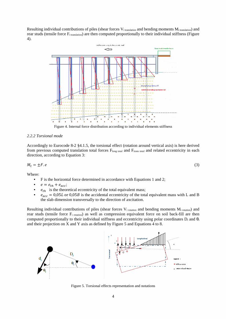
Resulting individual contributions of piles (shear forces Vi translation and bending moments Mi translation) and rear studs (tensile force Fi translation) are then computed proportionally to their individual stiffness (Figure 4).
Figure 4. Internal force distribution according to individual elements stiffness
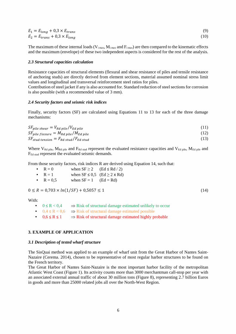
2.2.2 Torsional mode Accordingly to Eurocode 8-2 §4.1.5, the torsional effect (rotation around vertical axis) is here derived from previous computed translation total forces Flong total and Ftrans total and related eccentricity in each direction, according to Equation 3: � = ��. � (3) Where:
• F is the horizontal force determined in accordance with Equations 1 and 2; • � = ��� � ����; • ��� is the theoretical eccentricity of the total equivalent mass; • ���� = 0,05�or0,05 is the accidental eccentricity of the total equivalent mass with L and B
the slab dimension transversally to the direction of axcitation. Resulting individual contributions of piles (shear forces Vi rotation and bending moments Mi rotation) and rear studs (tensile force Fi rotation) as well as compression equivalent force on soil back-fill are then computed proportionally to their individual stiffness and eccentricity using polar coordinates Di and θi and their projection on X and Y axis as defined by Figure 5 and Equations 4 to 8.
Figure 5. Torsional effects representation and notations
2.2.4 Kinematic effect Kinematic effect due to soil deformation around the piles is considerate independently from previously described inertial effects. For this evaluation a simplified pseudo-static approach is used consisting in considering the piles are subjected to a quart of sinusoids deformation shape going from the ground surface to the bedrock limit as described on Figure 7.
Figure 7. Kinematic effect representation 2.2.5 Seismic combinations At the end, all of inertial effect contributions (horizontal translation, torsional effect and back-fill earth pressure) are summed on each pile and passive steel anchoring studs for both regular seismic combinations E1 and E2 as defined by Equations 9 and 10:
6
;, = ;���� � 0,3 × ;����� (9) ;) = ;����� � 0,3 × ;���� (10) The maximum of these internal loads (Vi max, Mi max and Fi max) are then compared to the kinematic effects and the maximum (envelope) of these two independent aspects is considered for the rest of the analysis. 2.3 Structural capacities calculation Resistance capacities of structural elements (flexural and shear resistance of piles and tensile resistance of anchoring studs) are directly derived from element sections, material assumed nominal stress limit values and longitudinal and transversal reinforcement steel ratios for piles. Contribution of steel jacket if any is also accounted for. Standard reduction of steel sections for corrosion is also possible (with a recommended value of 3 mm). 2.4 Security factors and seismic risk indices Finally, security factors (SF) are calculated using Equations 11 to 13 for each of the three damage mechanisms: ��="�(��(�� = 6>&="�( 6?&="�(⁄ (11) ��="�(@�(7A�( = >&="�( ?&="�(⁄ (12) ����A&�(��"�� = �>&��A& �?&��A&⁄ (13) Where VRd pile, MRd pile and FRd stud represent the evaluated resistance capacities and VEd pile, MEd pile and FEd stud represent the evaluated seismic demands. From those security factors, risk indices R are derived using Equation 14, such that:
• R = 0 when SF ≥ 2 (Ed ≤ Rd / 2) • R = 1 when SF ≤ 0,5 (Ed ≥ 2 x Rd) • R = 0,5 when SF = 1 (Ed = Rd)
• 0 ≤ R < 0,4 ⇒ Risk of structural damage estimated unlikely to occur • 0,4 ≤ R < 0,6 ⇒ Risk of structural damage estimated possible • 0,6 ≤ R ≤ 1 ⇒ Risk of structural damage estimated highly probable
3. EXAMPLE OF APPLICATION 3.1 Description of tested wharf structure The SisQuai method was applied to an example of wharf unit from the Great Harbor of Nantes Saint-Nazaire (Cerema. 2014), chosen to be representative of most regular harbor structures to be found on the French territory. The Great Harbor of Nantes Saint-Nazaire is the most important harbor facility of the metropolitan Atlantic West Coast (Figure 1). Its activity counts more than 3000 merchantman call-stop per year with an associated external annual traffic of about 30 million tons (Figure 8), representing 2.7 billion Euros in goods and more than 25000 related jobs all over the North-West Region.
7
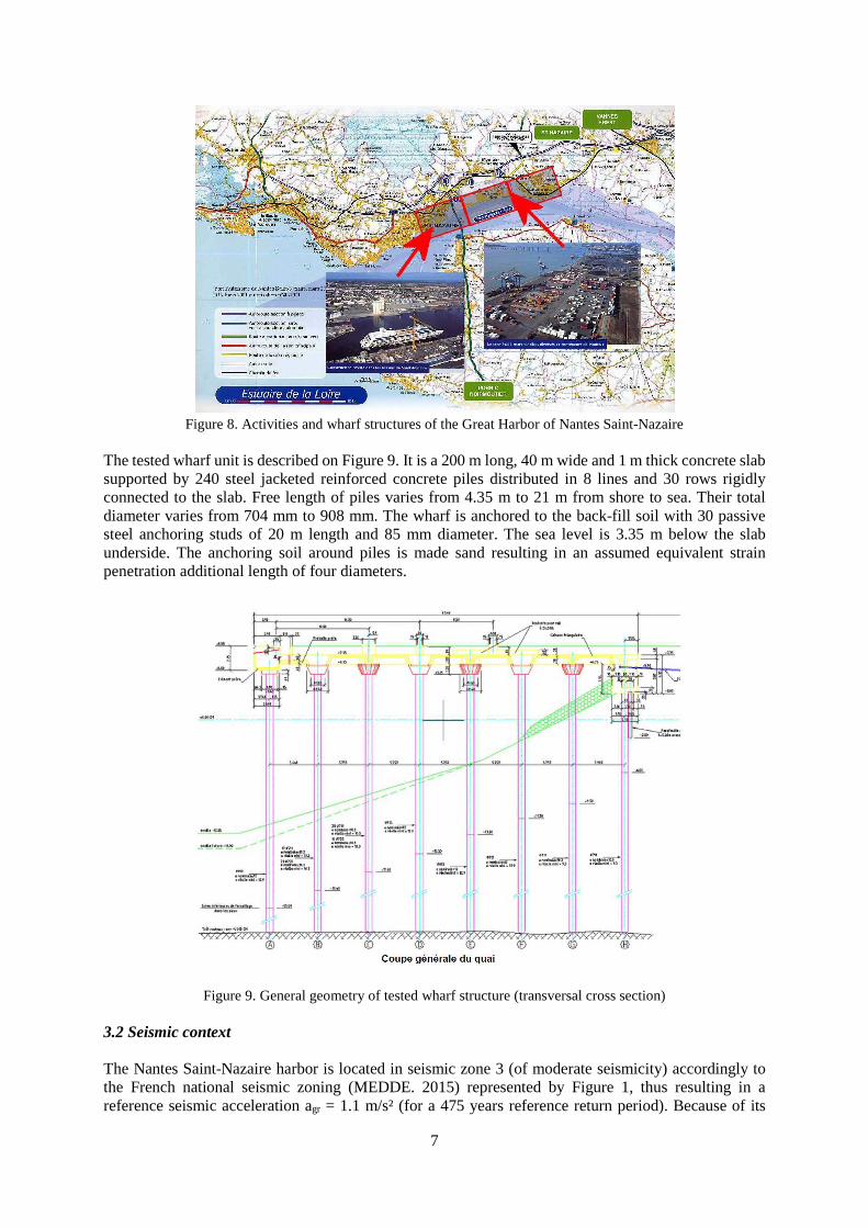
Figure 8. Activities and wharf structures of the Great Harbor of Nantes Saint-Nazaire
The tested wharf unit is described on Figure 9. It is a 200 m long, 40 m wide and 1 m thick concrete slab supported by 240 steel jacketed reinforced concrete piles distributed in 8 lines and 30 rows rigidly connected to the slab. Free length of piles varies from 4.35 m to 21 m from shore to sea. Their total diameter varies from 704 mm to 908 mm. The wharf is anchored to the back-fill soil with 30 passive steel anchoring studs of 20 m length and 85 mm diameter. The sea level is 3.35 m below the slab underside. The anchoring soil around piles is made sand resulting in an assumed equivalent strain penetration additional length of four diameters.
Figure 9. General geometry of tested wharf structure (transversal cross section) 3.2 Seismic context The Nantes Saint-Nazaire harbor is located in seismic zone 3 (of moderate seismicity) accordingly to the French national seismic zoning (MEDDE. 2015) represented by Figure 1, thus resulting in a reference seismic acceleration agr = 1.1 m/s² (for a 475 years reference return period). Because of its
8
strategical socio-economic importance, initial importance factor γI has been taken equal to 1.2, thus leading to a design acceleration value ag = 1.32 m/s² (with associated return period of 800 years). Sandy soil characteristics (soil class D) leads to consider a soil coefficient S = 1.6 and initial behavior factor q has been taken equal 1.5 (assumption of limited ductility). 3.3 Main results SisQuai analysis leads to evaluated fundamental vibration periods Tlong = 1.28 s in the longitudinal direction (parallel to the shore line) and Ttrans = 0.83 s in the transverse direction (perpendicular to the shore line orientated towards the sea), and associated spectral accelerations of 1.65 m/s² and 2.55 m/s² respectively (Figure 10).
Figure 10. Spectral response of the wharf structure in longitudinal and transversal directions resulting from SisQuai method
With initial assumptions (800 years design return period and limited ductility design hypothesis), the SisQuai simplified seismic assessment method results in risk indices Rpiles shear = 0, Rpiles flexure = 0,85 and Rstuds tension = 0,80 respectively for piles in shear, piles in flexure and anchoring studs in tension, thus corresponding to a risk of structural damage estimated highly probable for piles under seismic induced bending moments and passive steel anchoring studs under seismic induced tensile forces. However, it can be showed very easily that when considering less conservative assumption (i.e. 475 years classic reference return period and ductile design hypothesis with associated behavior factor q = 3 which can be justified by presence of steel jacketing around piles reinforced concrete sections), those risk indices can be brought back to more acceptable results as indicated in Table 1 and corresponding to risk of structural damage estimated unlikely to occur in piles and estimated possible in anchoring studs.
Table 1. SisQuai seismic risk indices results for two different calculation assumptions
SisQuai risk indices
Initial assumptions: 800 years return period
q = 1,5 (limited ductility)
Optimised assumptions: 475 years return period
q = 3 (dutile) Rpiles shear 0.00 0.00
Rpiles flexure 0.85 0.24
Rstuds tension 0.80 0.57
9
4. COMPARISION WITH 3D FINITE ELEMENT MODEL 4.1 Description of 3D model In order to validate and calibrate SisQuai simplified seismic assessment method, cross-checking of the results was achieved with a 3D finite element multimodal seismic analysis performed using Graitec corp. Advance@ structural analysis software. For this comparison the same example of regular wharf structure as described in previous chapter was used, except the fact that piles gross section has been considered instead of equivalent effective cracked inertia. Compared to SisQuai simplified approach, the 3D model presents many advantages:
• Deformability of the deck is taken into consideration; • Strain penetration of the piles deformation into the ground is directly computed by the model
from relative stiffness of the piles and the surrounding soil equivalent springs; • Superior vibration modes are considered; • Torsion mode effects is directly integrated in the calculation.
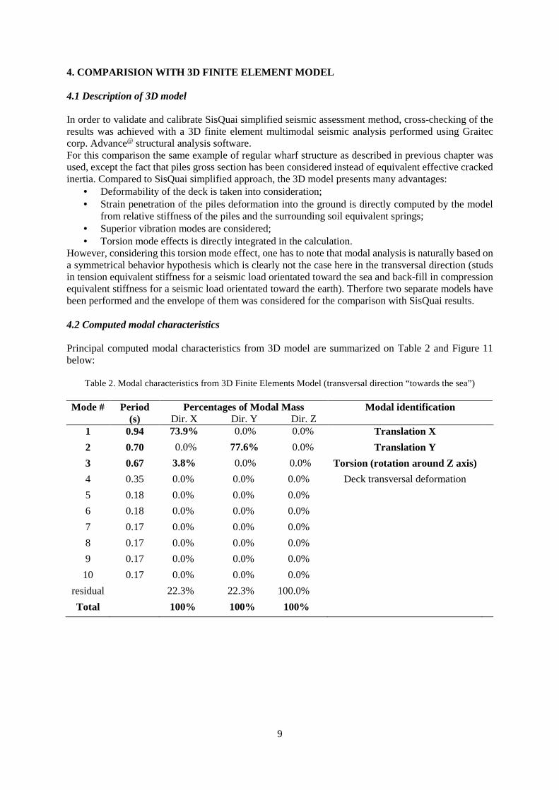
However, considering this torsion mode effect, one has to note that modal analysis is naturally based on a symmetrical behavior hypothesis which is clearly not the case here in the transversal direction (studs in tension equivalent stiffness for a seismic load orientated toward the sea and back-fill in compression equivalent stiffness for a seismic load orientated toward the earth). Therfore two separate models have been performed and the envelope of them was considered for the comparison with SisQuai results. 4.2 Computed modal characteristics Principal computed modal characteristics from 3D model are summarized on Table 2 and Figure 11 below:
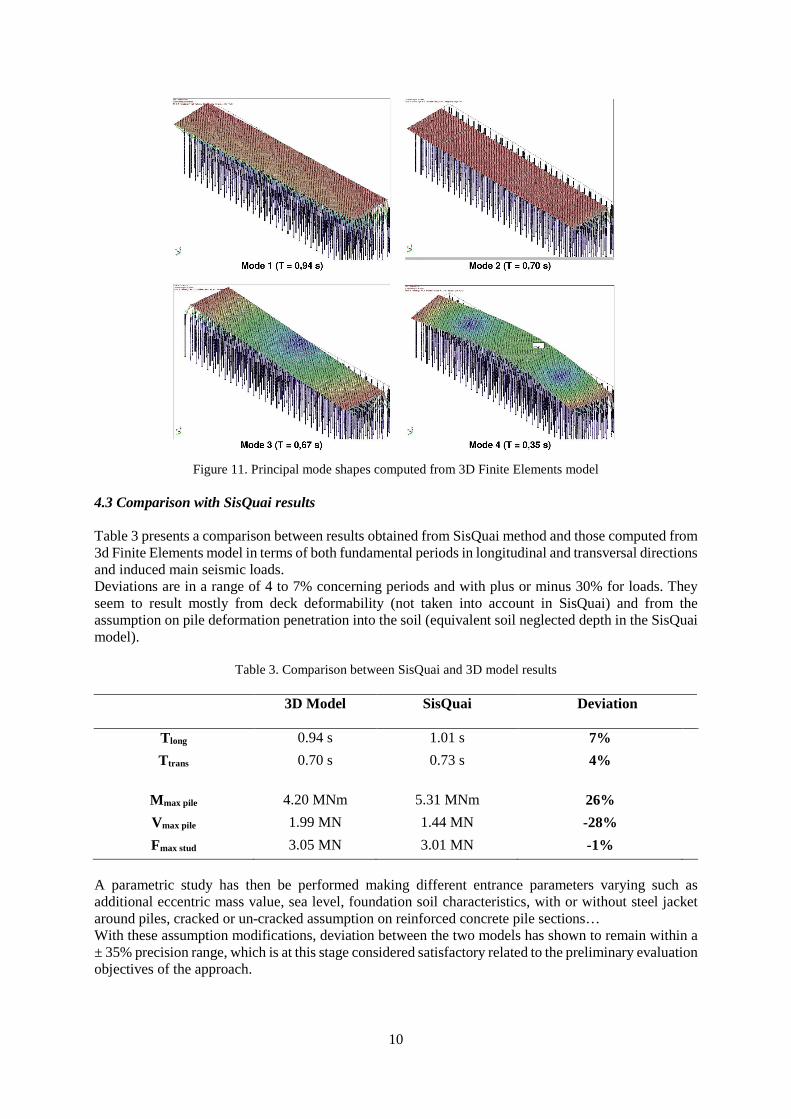
Table 2. Modal characteristics from 3D Finite Elements Model (transversal direction “towards the sea”) Mode # Period
(s) Percentages of Modal Mass
Dir. X Dir. Y Dir. Z Modal identification
1 0.94 73.9% 0.0% 0.0% Translation X
2 0.70 0.0% 77.6% 0.0% Translation Y
3 0.67 3.8% 0.0% 0.0% Torsion (rotation around Z axis)
Figure 11. Principal mode shapes computed from 3D Finite Elements model
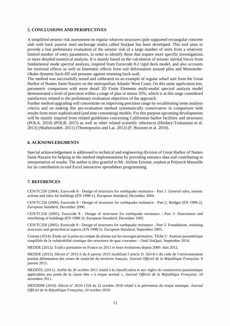
4.3 Comparison with SisQuai results Table 3 presents a comparison between results obtained from SisQuai method and those computed from 3d Finite Elements model in terms of both fundamental periods in longitudinal and transversal directions and induced main seismic loads. Deviations are in a range of 4 to 7% concerning periods and with plus or minus 30% for loads. They seem to result mostly from deck deformability (not taken into account in SisQuai) and from the assumption on pile deformation penetration into the soil (equivalent soil neglected depth in the SisQuai model).
Table 3. Comparison between SisQuai and 3D model results 3D Model SisQuai
Deviation
Tlong 0.94 s 1.01 s 7%
Ttrans 0.70 s 0.73 s 4%
Mmax pile 4.20 MNm 5.31 MNm 26%
Vmax pile 1.99 MN 1.44 MN -28%
Fmax stud 3.05 MN 3.01 MN -1%
A parametric study has then be performed making different entrance parameters varying such as additional eccentric mass value, sea level, foundation soil characteristics, with or without steel jacket around piles, cracked or un-cracked assumption on reinforced concrete pile sections… With these assumption modifications, deviation between the two models has shown to remain within a ± 35% precision range, which is at this stage considered satisfactory related to the preliminary evaluation objectives of the approach.
11
5. CONCLUSIONS AND PERSPECTIVES A simplified seismic risk assessment on regular wharves structures (pile supported rectangular concrete slab with back passive steel anchorage studs) called SisQuai has been developed. This tool aims to provide a fast preliminary evaluation of the seismic risk of a large number of units from a relatively limited number of entry parameters, in order to identify those that require more specific investigations or more detailed numerical analysis. It is mainly based on the calculation of seismic inertial forces from fundamental mode spectral analysis, inspired from Eurocode 8-2 rigid deck model, and also accounts for torsional effects as well as kinematic effects from soil deformation around piles and Mononobe-Okabe dynamic back-fill soil pressure against retaining back-wall. The method was successfully tested and calibrated on an example of regular wharf unit from the Great Harbor of Nantes Saint-Nazaire on the metropolitan Atlantic West Coast. On this same application test, parametric comparison with more detail 3D Finite Elements multi-modal spectral analysis model demonstrated a level of precision within a range of plus or minus 35%, which is at this stage considered satisfactory related to the preliminary evaluation objectives of the approach. Further method upgrading will concentrate on improving precision range by recalibrating some analysis criteria and on making this pre-evaluation method systematically conservative in comparison with results from more sophisticated (and time consuming) models. For this purpose upcoming developments will be mainly inspired from related guidelines concerning Californian harbor facilities and structures (POLA. 2010) (POLB. 2015) as well as other related scientific references (Heidary-Torkamani et al. 2013) (Shafieezadeh. 2011) (Thomopoulos and Lai. 2012) (F. Bozzoni et al. 2010). 6. ACKNOWLEDGMENTS Special acknowledgement is addressed to technical and engineering division of Great Harbor of Nantes Saint-Nazaire for helping in the method implementation by providing entrance data and contributing to interpretation of results. The author is also grateful to Mr. Jérôme Etienne, student at Polytech Marseille for its contribution to tool Excel interactive spreadsheet programming. 7. REFERENCES CEN/TC250 (2004). Eurocode 8 - Design of structures for earthquake resistance - Part 1: General rules, seismic actions and rules for buildings (EN 1998-1). European Standard, December 2004.
CEN/TC250 (2006). Eurocode 8 - Design of structures for earthquake resistance - Part 2: Bridges (EN 1998-2). European Standard, December 2006.
CEN/TC250 (2005). Eurocode 8 - Design of structures for earthquake resistance - Part 3: Assessment and retrofitting of buildings (EN 1998-3). European Standard, December 2005.
CEN/TC250 (2005). Eurocode 8 - Design of structures for earthquake resistance - Part 5: Foundations, retaining structures and geotechnical aspects (EN 1998-5). European Standard, September 2005.
Cerema (2014). Étude sur la prise en compte du séisme sur les ouvrages portuaires. Tâche 3 : Analyse paramétrique simplifiée de la vulnérabilité sismique des structures de quai courantes – Outil SisQuai. September 2014.
MEDDE (2012). Trafics portuaires en France en 2011 et leurs évolutions depuis 2000. Juin 2012.
MEDDE (2015). Décret n° 2015-5 du 6 janvier 2015 modifiant l’article D. 563-8-1 du code de l’environnement portant délimitation des zones de sismicité du territoire français. Journal Officiel de la République Française, 8 janvier 2015.
MEDDTL (2011). Arrêté du 26 octobre 2011 relatif à la classification et aux règles de construction parasismique applicables aux ponts de la classe dite « à risque normal ». Journal Officiel de la République Française, 10 novembre 2011.
MEEDDM (2010). Décret n° 2010-1254 du 22 octobre 2010 relatif à la prévention du risque sismique. Journal Officiel de la République Française, 24 octobre 2010.
12
METL (2012). Arrêté du 25 octobre 2012 modifiant l’arrêté du 22 octobre 2010 relatif à la classification et aux règles de construction parasismique applicables aux bâtiments de la classe dite « à risque normal ». Journal Officiel de la République Française, 30 octobre 2012.
POLA (2010). The Port of Los Angeles Code for Seismic Design, Upgrade and Repair of Container Wharves. POLA SEISMIC CODE 2010. City of Los Angeles Harbor Department, May 2010.
POLB (2015). Port of Long Beach Wharf Design Criteria. POLB WDC Version 4.0, May 2015.
Hamid Heidary-Torkamani, Khosrow Bargi & Rouhollah Amirabadi (2013). Seismic vulnerability assessment of pile-supported wharves using fragility curves, Structure and Infrastructure Engineering, 10:11, 1417-1431
Shafieezadeh, Abdollah (2011). Seismic vulnerability assessment of wharf structures. Georgia Institute of Technology, ProQuest Dissertations Publishing.
C. Thomopoulos & C. G. Lai (2012). Preliminary Definition of Fragility Curves for Pile-Supported Wharves, Journal of Earthquake Engineering, 16:sup1, 83-106.
F. Bozzoni, M. Corigliano, C.G. Lai and L. Scandella (2010). Seismic Risk Assessment of Italian Seaports using GIS and Guidelines for Seismic Design. PIANC MMX Congress Liverpool UK 2010.