111
SKF lubrication products and systems The industry’s most complete resource for knowledge-engineered lubrication solutions

SKF lubrication products and systemsThe industry’s most complete resource for knowledge-engineered lubrication solutions
SKF lubrication products and systems
® SKF, Vogel, SYSTEM 24, DialSet and OilSafe are registered trademarks of SKF USA Inc.® Safematic is a registered trademark of the John Crane Safematic Oy Company Finland.Safeflow is a trademark of SKF Group. Duoflex is a trademark of SKF USA Inc.The contents of this publication are the copyright of the publisher and may not be reproduced (even extracts) unless prior written permission is granted.Every care has been taken to ensure the accuracy of the information contained in this publication but no liability can be accepted for any loss or damage whether direct, indirect or consequential arising out of use of the information contained herein.
© 2007 SKF USA Inc. Publication 750-900 (30M/CW 6/2008) Version 6/2008 Printed in U.S.A.
SKF USA Inc.Kulpsville, PA 19443, USA
(215) 513-4400
www.skfusa.com


1
Table of contents
Lubricants 5
Automatic lubricators 37
Pre-engineered systems
Accessories 81
Manual lubrication 29
51

2
Thousands of lubrication points. One source for lubrication expertise.With more than 100 years of rotating machinery expertise, SKF® knows bearings. And since much of that expertise involves the science of tribology – the study of how friction affects moving parts – SKF knows lubrication, too.
For example, as much as 50% of premature bearing failures are caused by lubrication problems – too much, too little, the wrong type, or contaminated lubricant. Prevent-ing such lubrication-related failures, as well as ensuring optimal bearing performance,
Lubricants
The extensive line of SKF lubricants includes a range of greases and oils, and reflects decades of research and development across many industries. The comprehensive guide featured in this
catalog makes choosing the right lubricant easy – select the appropriate grease or oil according to the tempera-ture, speed and load ranges of a particular application.
Manual lubrication
Comprised of grease guns, packers, pumps and meters, SKF manual lubrication products give maintenance professionals many user-friendly tools to keep bearings supplied with precise
amounts of contaminant-free grease.
Automatic lubricators
From single-point to multi-point units, SKF automatic lubricators provide reli-able time- and labor-saving alternatives to manual lubrication. Around-the-clock SKF solutions such as SYSTEM 24®
and SYSTEM MultiPoint provide precise, contaminant-free grease, with minimal risk of over- or under-lubricating.
Pre-engineered systems
The SKF pre-engineered systems offering consists of systems from Vogel, a global leader in centralized lubrication and also part of SKF. These virtually maintenance-free lubrication systems
supply lubricant from a central source to the points on a machine at which friction occurs. Bearing wear and tear is reduced with minimal maintenance, and often, some of the friction-generated heat is dissipated with the help of the lubricant.

3
means delivering the right lubricant, in the right amount, at the right time, to the right lubrication point.
Today, SKF delivers a complete line of lubrication solutions to do exactly that.
With our acquisitions of Vogel® Lubrication, Inc. and the lubrication division of Safematic®, SKF lubrication products now range from lubricants themselves to state-of-the-art automatic and centralized lubrication systems.
Accessories
SKF lubrication accessories include a broad range of products designed to make lubrication safer, more efficient, and more convenient for operators. Disposable gloves improve worker
safety, while Oil Safe® dispensing and storage drums and lids protect against contamination. Small, portable daily lubrication kits and hand-held grease pumps make maintenance tasks easier, while large pumps for centralized and chain lubrication systems deliver measurable savings.

4

5
Lubricants Bearing grease selection basics 6
Bearing grease selection charts 7
Relubrication intervals 10
Lubrication methods 10
SKF bearing greases and their applications 11
Glossary of lubrication terms 16
Chain oil range 20
Dry lubricant for tabletop chain 21
Anti-fretting agent LGAF 3E 22
Anti-corrosive agent LHRP 1 22
Technical data 23

Lubricants
6
Even the very best bearing can only show optimum
performance when it is lubricated correctly. Here, it is extremely
important to choose the right bearing grease and to apply the
most suitable lubrication intervals and methods. This realization
has prompted SKF, the world’s leading manufacturer of rolling
bearings, to look intensively into the subject of lubrication. SKF
engineers consider grease to be a “fundamental” component of
the bearing arrangement and thus, as important as the bearing,
housing and sealing.
SKF’s vast experience in the development of rolling bearings
forms the basis for the development of a special range of
lubricants, the superior quality of which is obtained through
continuous testing and studies.
The strict standards and testing parameters developed and
applied at the SKF Engineering and Research Center have
become internationally recognized benchmarks for bearing
greases. The comprehensive range of SKF bearing greases is
the result of many decades of research and development. Each
individual lubricant is precisely adjusted to the respective field of
application.
SKF bearing greases: the perfect solution for every application
SKF sets the standardTangible performance parameters mean more to SKF than the chemical composition of the lubricant. The chemical composition is not the only factor in determining the quality of a particular grease, since modern lubricants are extremely complex. SKF has set the standards for developing special testing parameters.
Bearing grease selection Selecting the right bearing grease for a certain application is essential for achieving the maximum service life of a bearing. Selection criteria for correct lubrication include bearing type and size, temperatures, speeds and loads, as well as the desired service life and relubrication intervals. To select the proper SKF grease, refer to the reference table for temperature, speed and load ranges. SKF greases suitable for use in an application based on the combination of temperature, speed and load ranges are shown in the charts on pages 7-9. More information about all SKF greases can be found on pages 11 to 15 and in the technical information section on pages 23 to 28.
7
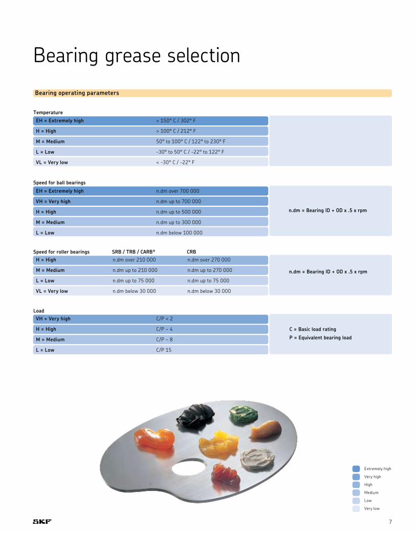
Bearing operating parameters
Bearing grease selection
Temperature
EH = Extremely high > 150° C / 302° F
H = High > 100° C / 212° F
M = Medium 50° to 100° C / 122° to 230° F
L = Low -30° to 50° C / -22° to 122° F
VL = Very low < -30° C / -22° F
Speed for ball bearings
EH = Extremely high n.dm over 700 000
VH = Very high n.dm up to 700 000
H = High n.dm up to 500 000
M = Medium n.dm up to 300 000
L = Low n.dm below 100 000
n.dm = Bearing ID + OD x .5 x rpm
Speed for roller bearings SRB / TRB / CARB® CRBH = High n.dm over 210 000 n.dm over 270 000
M = Medium n.dm up to 210 000 n.dm up to 270 000
L = Low n.dm up to 75 000 n.dm up to 75 000
VL = Very low n.dm below 30 000 n.dm below 30 000
n.dm = Bearing ID + OD x .5 x rpm
LoadVH = Very high C/P < 2
H = High C/P ~ 4
M = Medium C/P ~ 8
L = Low C/P 15
C = Basic load rating
P = Equivalent bearing load
Extremely high
Very high
High
Medium
Low
Very low
Lubricants
8
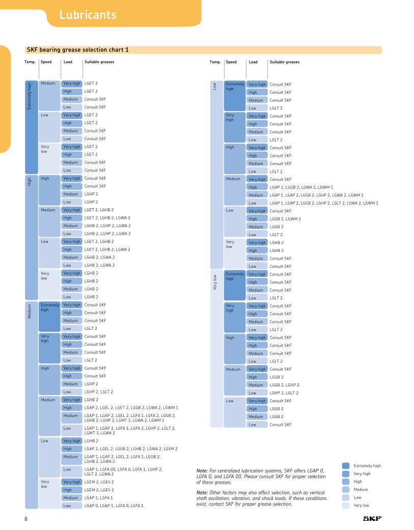
SKF bearing grease selection chart 1
Temp. Speed Load Suitable greases
Medium
Extr
emel
y hi
gh
Low
Very low
Very high LGET 2
High LGET 2
Medium Consult SKF
Low Consult SKF
Very high LGET 2
High LGET 2
Medium Consult SKF
Low Consult SKF
Very high LGET 2
High LGET 2
Medium Consult SKF
Low Consult SKF
Very high Consult SKF
High Consult SKF
Medium LGHP 2
Low LGHP 2
Very high LGET 2, LGHB 2
High LGET 2, LGHB 2, LGWA 2
Medium LGHB 2, LGHP 2, LGWA 2
Low LGHB 2, LGHP 2, LGWA 2
Very high LGET 2, LGHB 2
High LGET 2, LGHB 2, LGWA 2
Medium LGHB 2, LGWA 2
Low LGHB 2, LGWA 2
Very high LGHB 2
High LGHB 2
Medium LGHB 2
Low LGHB 2
Very high Consult SKF
High Consult SKF
Medium Consult SKF
Low LGLT 2
Very high Consult SKF
High Consult SKF
Medium Consult SKF
Low LGLT 2
Very high Consult SKF
High Consult SKF
Medium LGHP 2
Low LGHP 2, LGLT 2
Very high LGHB 2
High LGAP 2, LGEL 2, LGET 2, LGGB 2, LGWA 2, LGWM 1
Medium LGAP 1, LGAP 2, LGEL 2, LGFA 1, LGFA 2, LGGB 2, LGHB 2, LGHP 2, LGMT 3, LGWA 2, LGWM 1
Low LGAP 1, LGAP 2, LGFA 1, LGFA 2, LGHP 2, LGLT 2, LGMT 3, LGWA 2
Very high LGHB 2
High LGAP 2, LGEL 2, LGGB 2, LGHB 2, LGWA 2, LGVM 2
Medium LGAP 1, LGAP 2, LGEL 2, LGFA 1, LGGB 2, LGHB 2, LGWA 2
Low LGAP 1, LGFA 00, LGFA 0, LGFA 1, LGHP 2, LGLT 2, LGWA 2
Very high LGEM 2, LGEV 2
High LGEM 2, LGEV 2
Medium LGAP 1, LGFA 1
Low LGAP 0, LGAP 1, LGFA 0, LGFA 1
Hig
h High
Medium
Low
Very low
Med
ium Extremely
high
Very high
High
Medium
Low
Very low
Temp. Speed Load Suitable greases
Low
Very
low
Extremely high
Very high
High
Medium
Low
Very low
Extremely high
Very high
High
Medium
Low
Very high Consult SKF
High Consult SKF
Medium Consult SKF
Low LGLT 2
Very high Consult SKF
High Consult SKF
Medium Consult SKF
Low LGLT 2
Very high Consult SKF
High Consult SKF
Medium Consult SKF
Low LGLT 2
Very high Consult SKF
High LGAP 2, LGGB 2, LGWA 2, LGWM 1
Medium LGAP 1, LGAP 2, LGGB 2, LGHP 2, LGWA 2, LGWM 1
Low LGAP 1, LGAP 2, LGGB 2, LGHP 2, LGLT 2, LGWA 2, LGWM 1
Very high Consult SKF
High LGGB 2, LGWM 1
Medium LGGB 2
Low LGLT 2
Very high LGHB 2
High LGHB 2
Medium Consult SKF
Low Consult SKF
Very high Consult SKF
High Consult SKF
Medium Consult SKF
Low LGLT 2
Very high Consult SKF
High Consult SKF
Medium Consult SKF
Low LGLT 2
Very high Consult SKF
High Consult SKF
Medium Consult SKF
Low LGLT 2
Very high Consult SKF
High LGGB 2
Medium LGGB 2, LGHP 2
Low LGHP 2, LGLT 2
Very high Consult SKF
High LGGB 2
Medium LGGB 2
Low Consult SKF
Extremely high
Very high
High
Medium
Low
Very low
Note: Other factors may also affect selection, such as vertical shaft oscillation, vibration, and shock loads. If these conditions exist, contact SKF for proper grease selection.
Note: For centralized lubrication systems, SKF offers LGAP 0, LGFA 0, and LGFA 00. Please consult SKF for proper selection of these greases.
9
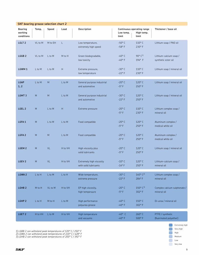
SKF bearing grease selection chart 2
Bearing Temp. Speed Load Description Continuous operating range Thickener / base oilworking Low temp. High temp.conditions limit limit
LGLT 2 VL to M M to EH L Low temperature, -50° C 110° C Lithium soap / PAO oil
extremely high speed -58° F 230° F
LGGB 2 VL to M L to M M to H Green biodegradable, -40° C 90° C1) Lithium-calcium soap /
low toxicity -40° F 194° F synthetic ester oil
LGWM 1 L to M L to M H Extreme pressure, -30° C 110° C Lithium soap / mineral oil
low temperature -22° F 230° F
LGAP L to M M L to M General purpose industrial -20° C 120° C Lithium soap / mineral oil
1, 2 and automotive -5° F 250° F
LGMT 3 M M L to M General purpose industrial -30° C 120° C Lithium soap / mineral oil
and automotive -22° F 250° F
LGEL 2 M L to M H Extreme pressure -20° C 110° C Lithium complex soap /
-5° F 230° F mineral oil
LGFA 1 M L to M L to M Food compatible -20° C 120° C Aluminum complex /
-5° F 250° F medical white oil
LGFA 2 M M L to M Food compatible -20° C 120° C Aluminum complex /
-5° F 250° F medical white oil
LGEM 2 M VL H to VH High viscosity plus -20° C 120° C Lithium soap / mineral oil
solid lubricants -5° F 250° F
LGEV 2 M VL H to VH Extremely high viscosity -10° C 120° C Lithium-calcium soap /
with solid lubricants -14° F 250° F mineral oil
LGWA 2 L to H L to M L to H Wide temperature, -30° C 140° C2) Lithium complex soap /
extreme pressure -22° F 284° F mineral oil
LGHB 2 M to H VL to M H to VH EP high viscosity, -20° C 150° C3) Complex calcium sulphonate /
high temperaure -5° F 302° F mineral oil
LGHP 2 L to H M to H L to M High performance -40° C 150° C Di-urea / mineral oil
polyurea grease -40° F 302° F
LGET 2 H to VH L to M H to VH High temperature -40° C 260° C PTFE / synthetic
and vacuums -40° F 500° F (fluorinated polyether)
1) LGBB 2 can withstand peak temperatures of 120° C / 250° F2) LGWA 2 can withstand peak temperatures of 220° C / 428° F3) LGHB 2 can withstand peak temperatures of 200° C / 392° F
Extremely high
Very high
High
Medium
Low
Very low
Lubricants
10
Relubrication intervalsChoosing the right bearing grease for a certain application is critical to bearing performance. Applying the correct quantity of grease at the right intervals is of equal importance. Over– or under–greasing as well as inadequate lubrication methods can shorten the bearing’s service life. For determining the right amount of grease and the correct relubrication intervals for a specific application, SKF has developed DialSet®, a simple computerized relubrication calculation program. Calculated relubrication intervals are based on the latest lubrication theories published in the SKF General Catalogue (6000 EN) and depend on bearing type used, application conditions and properties of selected bearing grease.
Lubrication methodsThe lubrication method used is equally important to the right bearing grease, quantity and lubrication intervals. Using lubricators, manual or automatic, facilitates proper lubricant supply to the application. Maintaining cleanliness when lubricating bearings is crucial, as contamination can cause the bearing to fail prematurely. Using a grease meter in combination with a grease gun or pump during manual lubrication helps ensure the supply of the right quantity of grease. SKF’s range of grease guns, pumps and lubrication accessories is designed for contamination–free grease supply as well as ease–of–use.
Continuous lubrication, using automatic lubricators or systems, provides the application with a consistent and controlled supply of bearing grease. This reduces the risk of over– or under–greasing and positively contributes to optimizing the bearing’s service life. Additionally, automatic relubrication reduces the risk of contamination. Around-the-clock solutions offered by SKF provide precise and reliable grease supply, adjusted to the application’s needs.
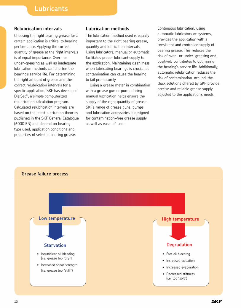
Grease failure process
High temperatureLow temperature
• Insufficient oil bleeding (i.e. grease too “dry”)
• Increased shear strength (i.e. grease too “stiff”)
Starvation Degradation
• Fast oil bleeding
• Increased oxidation
• Increased evaporation
• Decreased stiffness (i.e. too “soft”)

11
SKF Bearing greases and their applications LGAP 0, 1, 2
SKF general purpose industrial and automotive bearing grease
LGAP 0, 1, 2 is mineral oil based lithium soap thickened grease with excellent thermal stability within its operating temperature range. This premium quality, general purpose grease is suitable for a wide range of industrial and automotive applications.
• Excellent oxidation stability• Good mechanical stability• Excellent water resistance and rust inhibiting properties
Recommended applications• Agricultural equipment• Automotive wheel bearings• Conveyors• Small electric motors• Industrial fans
Other uses• Severe vibrations• Rust inhibiting properties
LGMT 3
SKF general purpose industrial and automotive bearing grease
LGMT 3 is mineral oil based lithium soap thickened grease. This premium quality, general purpose grease is suitable for a wide range of industrial and automotive applications.
• Excellent rust inhibiting properties• High oxidation stability within its recommended temperature range
Recommended applications• Bearings >100 mm (3.9 in) shaft size• Outer bearing ring rotation• Vertical shaft applications• Continuous high ambient temperatures >35° C (95° F)
• Propeller shafts• Agricultural equipment• Car, truck and trailer wheel bearings• Large electric motors
Other uses• Vertical shafts• Severe vibrations
LGEL 2
SKF high load, extreme pressure (EP) bearing grease
LGEL 2 is mineral oil based lithium soap thickened grease with extreme pressure additives. This grease provides good lubrication in operating temperatures ranging from –20° C (–5° F) up to 110° C (230° F).
• Excellent mechanical stability• Extremely good corrosion inhibiting properties
• Excellent EP performance
Recommended applications• Pulp and paper making machines• Jaw crushers• Traction motors for rail vehicles• Dam gates• Work roll bearings in steel industry• Heavy machinery, vibrating screens• Crane wheels, sheaves
Other uses• Severe vibrations• Shock load or frequent start-up• Rust inhibiting properties
(continued on following page)

Lubricants
12
LGWA 2
SKF high load, extreme pressure (EP), wide temperature range bearing grease
LGWA 2 is premium quality mineral oil based lithium complex grease with extreme pressure (EP) performance. LGWA 2 has such properties that it can be recommended for a wide range of industrial and automotive applications.
• Excellent lubrication at peak temperatures up to 220° C (428° F) for short periods
• Protection of wheel bearings operating under severe conditions
• Effective lubrication in wet conditions• Good water and corrosion resistance• Excellent lubrication under high loads and low speeds
Recommended applications• Wheel bearings in cars, trailers and trucks
• Washing machines• Electric motors
Other uses• Oscillating movements• Shock load or frequent start-up• Rust inhibiting properties
LGHB 2
SKF high load, high temperature, high viscosity bearing grease
LGHB 2 is a premium quality, high viscosity, mineral oil based grease using the latest complex calcium, sulphonate soap technology. This grease contains no additives and the extreme pressure characteristics are created within the soap structure.
• Excellent anti–oxidation and anti– corrosion properties
• Good EP performance in applications running at high loads
Recommended applications• Steel on steel plain bearings• Pulp and paper making machines• Asphalt vibrating screens• Continuous casting machines• Sealed spherical roller bearings operating up to 150° C (302° F)
• Withstands peak temperatures of 200° C (392° F)
• Work roll bearings in steel industry• Mast rollers of fork lift trucks
Other uses• Fast outer ring rotation• Oscillating movements• Severe vibrations• Shock load or frequent start-up• Rust inhibiting properties
LGHP 2
SKF high performance, high temperature bearing grease
LGHP 2 is premium quality mineral oil based grease, using a modern Polyurea (di–urea) thickener. It is suitable for ball (and roller) bearings required to run extremely quiet, operating at a wide temperature range from –40° C (–40° F) up to 150° C (302° F), at medium to high speeds.
• Extremely long life at high temperature
• Wide temperature range• Excellent corrosion protection• High thermal stability• Good low temperature start–up performance
• Compatibility with common Polyurea greases
• Compatibility with lithium complex thickened greases
• Low noise characteristics• Very good mechanical stability

13
LGET 2
SKF high temperature, extreme condition bearing grease
LGET 2 is premium quality, synthetic fluorinated oil based grease using a PTFE thickener. It has excellent lubrication properties at extremely high temperatures exceeding 200º C (392º F) up to 260º C (500º F).
• Long life in aggressive environments such as very reactive environments or areas with a presence of high purity gaseous oxygen or hexane
• Excellent oxidation resistance• Good corrosion resistance• Excellent water and steam resistance
Recommended applications• Bakery equipment (ovens)• Kiln truck wheels• Load rollers in copying machines• Wafer baking machines• Textile dryers• Film stretching tenders• Electric motors running at extreme temperatures
• Emergency / hot fans• Vacuum pumps
Other uses• Fast outer ring rotation• Oscillating movements
LGWM 1
SKF extreme pressure (EP) low temperature bearing grease
LGWM 1 is a mineral oil based grease using a lithium soap and containing extreme pressure additives. It is very suitable for the lubrication of bearings operating under both radial and axial loads e.g. transport screws.
• Good oil film formation at low temperatures down to –30° C (–22° F)
• Good pumpability at low temperature• Good corrosion protection• Good water resistance
Recommended applications• Windmills• Screw conveyors• Centralized lubrication systems• Spherical roller thrust bearing applications
Other uses• Oscillating movements• Shock load or frequent start-up• Rust inhibiting properties
(continued on following page)
LGHP 2
Recommended applications• Electric motors: small, medium and large• Industrial fans, including high speed fans• Water pumps• Rolling bearings in textile, paper processing and drying machines
• Applications with high speed ball bearings operating at medium and high temperatures
• Clutch release bearings• Kiln trucks and rollers• Vertical shaft applications• Vibrating applications
Other uses• Vertical shafts• Severe vibrations• Low noise• Rust inhibiting properties

Lubricants
14
LGLT 2
SKF low temperature, extremely high speed bearing grease
LGLT 2 is premium quality, fully synthetic oil based grease using lithium soap. Its unique thickener technology and its low viscosity oil (PAO) provide excellent lubrication performance at low temperatures (–50° C) and extremely high speeds, n.dm values of 1.6 × 10⁶ can be reached.
• Low friction torque• Low level of power loss • Quiet running behavior• Extremely good oxidation stability and resistance to water
Recommended applications• Textile spinning spindles• Machine tool spindles• Instruments and control equipment• Small electric motors used in medical and dental equipment
• In–line skates• Printing cylinders
• Robots
Other uses• Low noise• Low friction
LGEM 2
SKF high viscosity bearing grease with solid lubricants
LGEM 2 is a premium quality, high viscosity, mineral oil based grease using a lithium soap containing molybdenum disulphide and graphite.
• Good lubrication for bearings operating under high loads and slow rotations
• Safe lubrication due to the inclusion of molybdenum disulphide and graphite
Recommended applications• Rolling element bearings running at low speed and very high loads
• Jaw crushers• Track laying machines• Lift mast wheels• Building machines such as mechanical rams, crane arms and crane hooks
Other uses• Oscillating movements• Severe vibrations• Shock load or frequent start-up• Rust inhibiting properties
LGEV 2
SKF extremely high viscosity bearing grease with solid lubricants
LGEV 2 is a premium quality, extremely high viscosity, mineral oil based grease using a lithium–calcium soap containing molybdenum disulphide and graphite.
• Excellent lubrication properties due to the inclusion of molybdenum disulphide and graphite solid
• Very suitable for lubricating large sized spherical roller bearings subject to high loads and slow rotation, a situation where microslip is likely to occur
• Extremely mechanically stable providing good water resistance and corrosion protection
Recommended applications• Trunnion bearings on rotating drums• Support and thrust rollers on rotary kilns and dryers
• Bucket wheel excavators• Slewing ring bearings• High pressure roller mills• Crushers
Other uses• Oscillating movements• Severe vibrations• Shock load or frequent start-up• Rust inhibiting properties
15
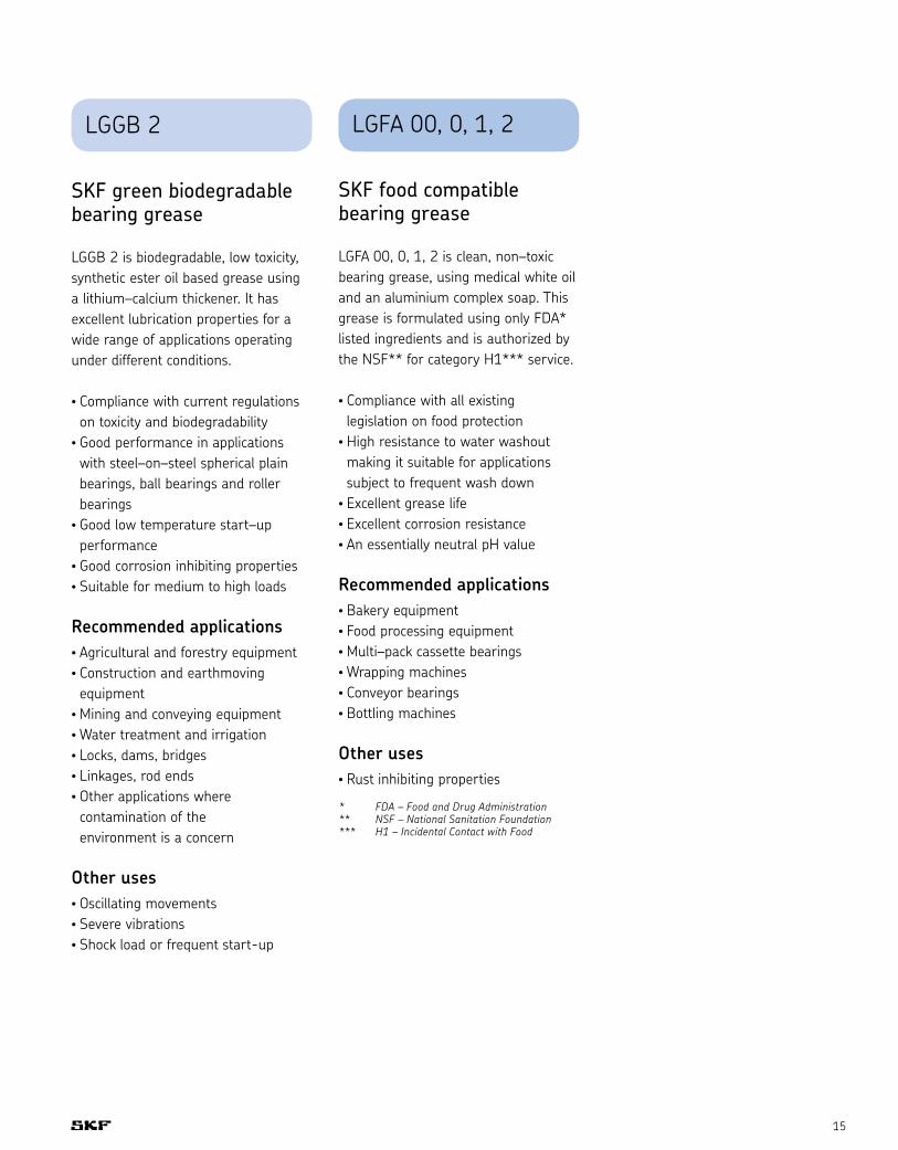
LGFA 00, 0, 1, 2
SKF food compatible bearing grease
LGFA 00, 0, 1, 2 is clean, non–toxic bearing grease, using medical white oil and an aluminium complex soap. This grease is formulated using only FDA* listed ingredients and is authorized by the NSF** for category H1*** service.
• Compliance with all existing legislation on food protection
• High resistance to water washout making it suitable for applications subject to frequent wash down
• Excellent grease life• Excellent corrosion resistance• An essentially neutral pH value
Recommended applications• Bakery equipment• Food processing equipment• Multi–pack cassette bearings• Wrapping machines• Conveyor bearings• Bottling machines
Other uses• Rust inhibiting properties
* FDA – Food and Drug Administration** NSF – National Sanitation Foundation*** H1 – Incidental Contact with Food
LGGB 2
SKF green biodegradable bearing grease
LGGB 2 is biodegradable, low toxicity, synthetic ester oil based grease using a lithium–calcium thickener. It has excellent lubrication properties for a wide range of applications operating under different conditions.
• Compliance with current regulations on toxicity and biodegradability
• Good performance in applications with steel–on–steel spherical plain bearings, ball bearings and roller bearings
• Good low temperature start–up performance
• Good corrosion inhibiting properties• Suitable for medium to high loads
Recommended applications• Agricultural and forestry equipment• Construction and earthmoving equipment
• Mining and conveying equipment• Water treatment and irrigation• Locks, dams, bridges• Linkages, rod ends• Other applications where contamination of the environment is a concern
Other uses• Oscillating movements• Severe vibrations• Shock load or frequent start-up

Lubricants
16
Glossary of lubrication termsThickener or soapThickener or soap is the system which holds the oil and/or additives together to enable the lubricating grease to
function. The thickener system is formed from either soaps or non–soaps. The type of thickener gives the grease its typical characteristics.
Soaps are based on lithium, calcium, sodium, barium or aluminium. Non–soaps are based on organic or non–organic solids, bentonite clay, polyurea or silica gel.
Thickener compatibility chart Lithium Calcium Sodium Lithium Calcium Sodium Barium Aluminium Clay Common Calcium complex complex complex complex complex Polyurea sulphonate complex
= Compatible = Test required = Incompatible
LithiumCalciumSodiumLithium complex
Calcium complex
Sodium complex
Barium complex
Aluminium complex
ClayCommon Polyurea
Calcium sulphonate complex
= Compatible = Test required = Incompatible
Base oil compatibility chart Mineral/PAO Ester Polyglycol Silicone: Silicone: Polyphenyl- PFPE methyl phenyl ether
Mineral oil / PAO Ester Polyglycol Silicone: methylSilicone: phenylPolyphenyletherPFPE
Note: SKF high performance, high temperature bearing grease LGHP 2 is not a common polyurea type grease. It is a di–urea bearing grease, which has successfully been tested for compatibility with lithium and lithium complex thickened greases i.e. LGHP 2 is compatible with such greases.

17
Base oilThe base oil is the oil inside the grease, which provides lubrication under operating conditions. Greases are normally based on mineral oils. Synthetic oils can be used for very specific applications such as extremely high or low temperatures. The base oil generally constitutes more than 70% of a grease’s composition.
Base oil viscosityViscosity is a measure of a fluid’s flow characteristics and is usually expressed in terms of the time required for a standard quantity of the fluid, at a given temperature, to flow through a standard orifice. Since viscosity decreases with increasing temperature, the temperature at which it is measured is always stated. The viscosity of base oils is always indicated as a kinematic viscosity abbreviated to cSt, at 40° C (104° F) and often also at 100° C (212° F).
AdditivesAdditives are used to provide additional characteristics such as wear and corrosion protection, friction reducing effects and preventing damage under boundary and mixed lubrication conditions.
Grease consistency/penetrationA measure of the stiffness of a grease. The consistency is classified according to a scale developed by the NLGI (National Lubricating Grease Institute). This is based on the degree of penetration achieved by allowing a standard cone to sink into the grease at a temperature of 25° C (77° F) for a period of five seconds. The depth of penetration is measured on a scale of 10-1 mm and the softer greases allow the cone to penetrate further into the grease, hence the higher penetration number. The test method is in accordance with DIN ISO 2137. Refer to chart below
Drop pointThe drop point is the temperature at which the grease sample, when heated, will begin to flow through an opening and is measured according to DIN ISO 2176. The drop point does not relate to the allowable operating service temperature of the grease.
Mechanical stabilityThe consistency of a rolling bearing grease should not alter, or only slightly be altered during the working life of the rolling bearing. Depending on the application, the following tests can be performed to evaluate the mechanical stability of a grease.
Prolonged penetration testThe grease sample is filled into a cup and, using an automatic device (called a grease worker) subjected to 100,000 double strokes. At the end of the test, the penetration of the grease is measured. The difference between the measured penetration at 60 strokes and after 100,000 strokes penetration is reported as the change in 10-1 mm.Classification of greases by NLGI consistency number
NLGI ASTM worked Appearance at number penetration (10-1 mm) room temperature
000 445 – 475 very fluid 00 400 – 430 fluid 0 355 – 385 semi–fluid 1 310 – 340 very soft 2 265 – 295 soft 3 220 – 250 medium hard 4 175 – 205 hard 5 130 – 160 very hard 6 85 – 115 extremely hard

Lubricants
18
Roll stability testThe change in the grease structure (amount of softening or hardening) can be evaluated by filling a cylinder with a pre–specified quantity of grease. A roller is placed inside the cylinder and the complete unit is rotated for 2 hours at room temperature in accordance with ASTM D 1403. SKF modified the standard test procedure to reflect the application conditions under which the grease is used to either 72 or 100 hours at a test temperature of 80° C (176° F) or 100° C (212° F) respectively. At the end of the test period, the cylinder is allowed to cool to room temperature and the penetration of the grease is measured. The difference between the original penetration and the value measured is reported as the change in penetration in 10-1 mm.
SKF V2F testThe candidate grease is tested for mechanical stability using the following procedure. The test rig consists of a railway axle box subjected to vibration shocks of 1Hz from a bouncing hammer producing an acceleration force level between 12 – 15 g’s. The test is run at two different speeds, 500 and 1,000 rpm. If the grease, which leaks from the housing through the labyrinth seal which is collected in a tray after 72 hours at 500 rpm, weighs less than 50 grams, the test is continued for a further 72 hours at 1,000 rpm. If the total amount of grease leakage after both tests (72 hours at both 500 and 1,000 rpm) does not exceed 150 grams, then a rating of ‘M’ is given. If the grease only fulfills the first part of the test (72 hours at 500 rpm with a grease leakage of 50 grams or less) but fails the second stage, a rating of ‘m’ is given. If the grease leakage after 72
hours at 500 rpm is greater than 50 grams, then it is rated as failed.
Corrosion protectionLubricating greases should protect metal surfaces from corrosive attack in service. The corrosion protection properties of rolling bearing greases are evaluated using the SKF Emcor method, which is standardized under ISO 11007. Under this test method a mixture of lubricating grease and distilled water is present in the bearing. The bearing alternates during a defined test cycle between standstill and rotation at 80 rpm. At the end of the test cycle, the degree of corrosion is evaluated according to a scale between 0 (no corrosion) and 5 (very severe corrosion). A more severe test method is to use salt water to replace the distilled water following the standard test procedure. In addition, the test can also be carried out by continuously allowing water to flow or wash through the bearing arrangement during the test cycle. This test method is called the SKF Distilled Water Washout Test. The evaluation procedure is exactly the same as that used under the standardized method. However the procedure places greater demands on the corrosion protection properties of the grease.
Copper corrosionLubricating greases should protect copper alloys used in bearings from corrosive attack while in service. The copper corrosion protection properties of rolling bearing greases are evaluated using the standardized method DIN 51811. A copper strip is immersed in the grease sample and placed in an oven. The strip is then cleaned and the degradation is observed. The result is rated by a numerical system.
Water resistanceThe water resistance of lubricating greases is measured in accordance with DIN 51 807 part 1. A glass strip is coated with the candidate grease, which is placed into a water–filled test tube. The test tube is immersed in a water bath for three hours at a specified test temperature. The change in the grease is evaluated visually and reported as a value between 0 (no change) and 3 (major change) along with the test temperature.
Oil separationLubricating greases release oil when stored for long periods of time or when used in bearings as a function of temperature. This phenomenon is necessary to ensure good lubrication. The degree of oil separation will depend upon the thickener, base oil and manufacturing method. A cup is filled with a given quantity of grease (which is weighed before the test) and a 100 gram weight placed on top of the grease. The complete unit is put into an oven at 40° C (104° F) for one week. At the end of the week, the amount of oil which has leaked through the sieve is weighed and reported as a percentage of weight loss. The amount of oil separation is measured in accordance with DIN 51 817.

19
Lubricating abilityThe SKF R2F machine assesses the high temperature performance and lubricating ability of a grease, simulating the conditions under which large size bearings operate in housings. The test method is carried out under two different conditions. Test A is conducted at ambient temperature and Test B is conducted at 120° C (248° F). A pass rating in the unheated test (Test A) means that a grease can be used to lubricate larger rolling bearings at normal operating temperatures and also in low vibrating applications. A pass in the heated test (Test B) at 120° C (248° F) means that the grease is suitable for use in large roller bearings operating at elevated temperatures.
Rolling bearing grease lifeThe SKF R0F grease test machine determines the grease life and high temperature performance limit of a lubricating grease. Ten deep groove ball bearings are fitted into 5 housings and filled with a given quantity of grease. The test is undertaken at a pre–determined speed and temperature. Both an axial and radial load is applied and the bearings run until failure. The time to failure is recorded in hours and a Weibull life calculation is made at the end of the test period to establish the grease life. This information can be used to determine relubrication intervals in an application.
EP performancesThe 4–ball weld load test This method evaluates the EP (Extreme Pressure) performance of a lubricating grease. This test method is standardized under DIN 51 350/4. Three steel balls are held in a cup and a fourth ball is rotated against the three balls at a given speed. A starting load is applied and increased at predetermined intervals until the rotating ball seizes and welds to the three stationary balls. The test indicates the point at which the extreme pressure limit of the grease is exceeded. Greases can be considered as EP greases when the weld load is higher than 2,600 N.
The 4–ball wear scar testThis test is performed with the same rig used in the 4–ball weld load test. 1,400 N are applied on the fourth ball for one minute. Then the wear on the three balls is measured. A standard test uses a load of 400 N. However, SKF has decided to increase that to 1,400 N in order to make the test relevant for bearing applications.
False brinellingAnti–fretting properties of a grease can be relevant for certain applications. SKF can assess these properties using the FAFNIR test standardized as ASTM D4170. Two ball thrust bearings are loaded and oscillated. The wear on each bearing is then measured. Greases offer good fretting protection when the measured wear is below7 mg.

Lubricants
20
Extending chain life
SKF chain oils come in three convenient sizes to suit the needs of most chain applications in industrial environments. The chain oils, medium temperature, high temperature, and food compatible (NSF H1), are available in 400 ml (13.52 oz.) aerosol cans, 5 liter (1.32 gallon) cans, and as an oil fill for the SYSTEM 24 single point automatic lubricator.
Chain oil rangeOrdering detailsDesignation DescriptionLHFP 150/0.4 400 ml (13.52 oz.) aerosol can LHFP 150/5 5 liter (1.32 gallon) can LAGD 125/HFP15* 125 ml (4.25 fl. oz.) SYSTEM 24 unit filled with food processing oil (viscosity ISO 150) LHHT 265/0.4 400 ml (13.52 oz.) aerosol can LHHT 265/5 5 liter (1.32 gallon) can LAGD 125/HHT26* 125 ml (4.25 fl. oz.) SYSTEM 24 unit filled with synthetic high temperature chain oil (viscosity ISO 265) LHMT 68/0.4 400 ml (13.52 oz.) aerosol can LHMT 68/5 5 liter (1.32 gallon) can LAGD 125/HMT68* 125 ml (4.25 fl. oz.) SYSTEM 24 unit filled with mineral EP type chain oil (viscosity ISO 68) LAGD 60/HMT68* 60 ml (2.03 fl. oz.) SYSTEM 24 unit filled with mineral EP type chain oil (viscosity ISO 68) * Includes non–return valve

21
Dry lubricant for tabletop chainLDTS 1
LDTS 1 oil has been especially developed for the automatic lubrication of conveyors in the food processing industry. The base oils and additives of this lubricant comply with the FDA regulations and can be used according to EC regulations for incidental contacts with foodstuffs.
CharacteristicsLDTS 1 contains:• No toxic components and does not stain
• Contains PTFE as solid lubricant• Has very good penetrating properties due to low viscosity
• Adheres very well to all treated surfaces after evaporation of the solvent
• Has good anti-wear properties
LDTS 1 is registered in the “NSF White Book”, NSF H1 Registration Number 128471 and registered by the German independent laboratory Isega under the Registration Number 18076 U 03.
Technical details and applicationsLDTS 1 is a lubricant approved for the lubrication of conveyors made of plastic or metal. It minimizes the wear of conveyors when loaded. Its PTFE content avoids the ‘stick-slip’ phenomenon. When applied, this lubricant leaves a dry lubricating film, which ensures good protection against wear of all mechanical sliding parts of conveyors. LDTS 1 has an anti-wear effect on partially worn conveyors.
LDTS 1 is formulated to be applied through automatic centralized lubrication systems on conveyors such as automatic machines to fill fruit juices, milk and beverages in cardboard cartons, plastic or glass bottles and aluminum cans. No water-soluble lubricating agents (water and soap) are needed, reducing the disadvantages of humidity, slippery floors, foam and corrosion as well as bacterial development in equipment and plants.
LDTS 1 Values Units
Composition Mineral oils, hydrocarbons, additives, PTFE –
Viscosity at 40° C (104° F) ca 11 mm2/s
Color White –
Temperature range -5° to +60° C (+23° to +140° F) ° C
Pour point < 0 ° C
Density: 20° C (68° F) ca 843 kg/m3
Flash point of the preparation ca 100 ° C
Flash point after evaporation of the solvent > 170 ° C
Product packaged in 5 liter cans; 4 cans per case
Ordering details Units
LDTS 1 / 5 5L can
Lubricants
22
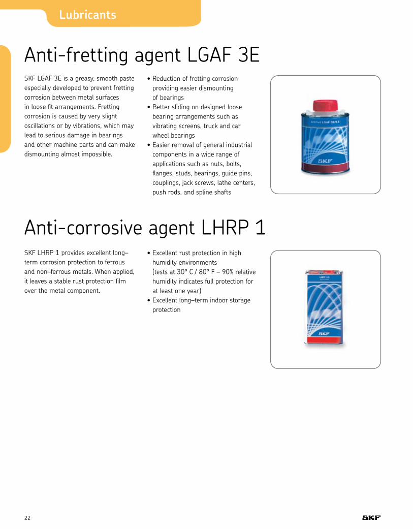
Anti-fretting agent LGAF 3ESKF LGAF 3E is a greasy, smooth paste especially developed to prevent fretting corrosion between metal surfaces in loose fit arrangements. Fretting corrosion is caused by very slight oscillations or by vibrations, which may lead to serious damage in bearings and other machine parts and can make dismounting almost impossible.
• Reduction of fretting corrosion providing easier dismounting of bearings
• Better sliding on designed loose bearing arrangements such as vibrating screens, truck and car wheel bearings
• Easier removal of general industrial components in a wide range of applications such as nuts, bolts, flanges, studs, bearings, guide pins, couplings, jack screws, lathe centers, push rods, and spline shafts
Anti-corrosive agent LHRP 1SKF LHRP 1 provides excellent long–term corrosion protection to ferrous and non–ferrous metals. When applied, it leaves a stable rust protection film over the metal component.
• Excellent rust protection in high humidity environments (tests at 30° C / 80° F – 90% relative humidity indicates full protection for at least one year)
• Excellent long–term indoor storage protection

23
Technical data LHRP 1 LGAF 3E LHMT 68 LHHT 265 LHFP 150Description Anti–corrosive Anti–fretting Medium High Food compatible, agent paste temperature oil temperature oil NSF H1 oil
Specific gravity 0.815 1.19 0.85 0.91 0.85
Color Hazy brown White–beige Yellow–brown Yellow–orange Colorless
Base oil type Mineral Mineral and Mineral Synthetic ester Synthetic ester synthetic
Thickener Not applicable Lithium soap Not applicable Not applicable Not applicable
Operating temperature – –25 to 250° C –15 to 90° C Up to 250° C –30 to 120° C range, ºC (ºF) – (–13 to 482° F) (5 to 194° F) (482° F) (–22 to 248° F)
Base oil viscosity: 20º C, mm2/s not valid because – – – – 40º C, mm2/s of thixotropic 17.5 ISO VG 68 approx. 265 ISO VG 150 100º C, mm2/s nature – approx. 9 approx. 30 approx. 19
Flash point 39° C – 200° C approx. 260° C > 200° C (102° F) (392° F) (500° F) (392° F)
Pour point –20° C – –15° C – < –30° C (-4° F) (5° F) – (–22° F)
NSF approval Not applicable Not applicable Not applicable Not applicable H1 (No: 136858)
Available pack sizes 5 liter can – 125 ml automatic 125 ml automatic 125 ml automatic 180 liter drum 0.5 kg can lubricator lubricator lubricator – – SYSTEM 24 SYSTEM 24 SYSTEM 24 400 ml aerosol can 400 ml aerosol can 400 ml aerosol can 5 liter can 5 liter can 5 liter can
Designation LHRP 1 / LAGF 3E / 0.5 LAGD 125 / HMT68 LAGD 125 / HHT26 LAGD 125 / HFP15 (pack size) LHMT 68 / LHHT 265 / LHFP 150 / (pack size) (pack size) (pack size)
Chemicals and oils LHRP 1 (page 22) LGAF 3E (page 22) LHMT 68, LHHT 265, LHFP 150 (page 20)

Lubricants
24
Bearing greases (pages 11 - 15) LGAP 0 LGAP 1 LGAP 2 LGEL 2
NLGI 0 1 2 2
Soap type / thickener Lithium Lithium Lithium Lithium complex
Color Amber Amber Amber Blue
Base oil type Mineral Mineral Mineral Mineral
104° F / 40° C, [mm2/s] 210 210 210 210
Operating temperature range [°F] -5° F / +250° F -5° F / +250° F -5° F / +250° F -5° F / +290° F
Dropping point, [°F]
DIN ISO 2176, [°F] – – – 500° F min
Penetration DIN ISO 2137
60 strokes, [10-1 mm] 355-385 310-340 265-295 265-295
100 000 strokes, [10-1 mm] +50 max +50 max +50 max +50 max
Mechanical stability
Roll stability, 50 h, +80° C, [10-1 mm] +50 max +50 max +50 max +50 max
Water resistance
ASTM D 1264, [%] - 5 max 5 max 5 max
Oil separation
DIN 51817 1-5 1-5 1-5 1-5
Copper corrosion
ASTM D 4048 2 max 2 max 2 max 2 max
Rust test rating
ASTM D 1743, [ - ] Pass Pass Pass Pass
EP performance
Wear scar, ASTM D 2266 [mm] 0.60 0.60 0.60 0.60
Weld load, ASTM D 2596 [kgf] 250 250 250 315
Weld load, Timken [lbs.] 40 40 40 60
Oxidation stability 5 max 5 max 5 max 5 max
ASTM D 942, [psi drop]
Wheel bearing leakage
ASTM D 1263 - - - 6 max
Rolling bearing grease life
SKF R0F L50 life at 10,000 rpm, +120° C, [hrs.] - - 1000 min. -
Water content
DIN 51777, ASTM D 1744, [%] 0.2 max 0.2 max 0.2 max 0.2 max
Available pack size 14 oz. 14 oz. 14 oz. 14 oz.
35 lb. 35 lb. 35 lb. 35 lb.
120 lb. 120 lb. 120 lb. 120 lb.
400 lb. 400 lb. 400 lb. 400 lb.
Designation - LGAP 1 / 14CART LGAP 2 / 14CART LGEL 2 / 14CART
LGAP 0 / 35PAIL LGAP 1 / 35PAIL LGAP 2 / 35PAIL LGEL 2 / 35PAIL
LGAP 0 / 120KEG LGAP 1 / 120KEG LGAP 2 / 120KEG LGEL 2 / 120KEG
LGAP 0 / 55DRUM LGAP 1 / 55DRUM LGAP 2 / 55DRUM LGEL 2 / 55DRUM

25
Bearing greases (pages 11 - 15) LGFA 00 LGFA 0 LGFA 1 LGFA 2
NLGI 00 0 1 2
Soap type / thickener Aluminum complex Aluminum complex Aluminum complex Aluminum complex
Color White White White White
Base oil type White mineral White mineral White mineral White mineral
100° F / 40° C, [mm2/s] 68 68 68 68
Operating temperature range [°F] -5° F / +250° F -5° F / +250° F -5° F / +250° F -5° F / +250° F
Dropping point, [°F]
DIN ISO 2176, [°F] – 450° F min 500° F min 500° F min
Penetration DIN ISO 2137
60 strokes, [10-1 mm] 400-430 355-385 310-340 265-295
100 000 strokes, [10-1 mm] – – +50 max +50 max
Mechanical stability
Roll stability, 50 h, +80° C, [10-1 mm] +50 max +50 max +50 max +50 max
Water resistance
ASTM D 1264, [%] - – 5 max 5 max
Oil separation
DIN 51817 2-5 2-5 2-5 2-5
Copper corrosion
ASTM D 4048 2 max 2 max 2 max 2 max
Rust test rating
ASTM D 1743, [ - ] Pass Pass Pass Pass
EP performance
Wear scar, ASTM D 2266 [mm] 0.60 0.60 0.60 0.60
Weld load, ASTM D 2596 [kgf] – – – 400
Weld load, Timken [lbs] 40 40 40 40
Oxidation stability 5 max 5 max 5 max 5 max
ASTM D 942, [psi drop]
Wheel bearing leakage
ASTM D 1263 – – – –
Rolling bearing grease life
SKF R0F L50 life at 10,000 rpm, +120° C, [hrs.] – – – 1000 min.
Water content
DIN 51777, ASTM D 1744, [%] 0.2 max 0.2 max 0.2 max 0.2 max
Available pack size 35 lb. 14 oz. 14 oz. 14 oz.
120 lb 35 lb. 35 lb. 35 lb.
400 lb. 120 lb. 120 lb. 120 lb.
400 lb. 400 lb. 400 lb.
Designation LGFA 00 / 35PAIL – LGFA 1 / 14CART LGFA 2 / 14CART
LGFA 00 / 120KEG LGFA 0 / 35PAIL LGFA 1 / 35PAIL LGFA 2 / 35PAIL
LGFA 00 / 55DRUM LGFA 0 / 120KEG LGFA 1 / 120KEG LGFA 2 / 120KEG
LGFA 0 / 55DRUM LGFA 1 / 55DRUM LGFA 2 / 55DRUM

Lubricants
26
DIN 51825 code K3K–30 KP2G–50 K2N–40
NLGI consistency class 3 2 2–3
Soap type / thickener Lithium Lithium Di–urea complex Color Amber Beige Blue
Base oil type Mineral PAO Mineral Operating temperature range, ºC (ºF) –30° to 120° C –50° to 110° C –40° to 150° C (–22° to 250° F) (–58° to 230° F) (–40° to 300° F)
Dropping point DIN ISO 2176, ºC (ºF) 180 min. 180 min. 240 min.. (356 min.) (356 min.) (464 min.)Base oil viscosity: 40º C, mm2/s 120–130 18 96 100º C, mm2/s 12 4.5 10.5
Penetration DIN ISO 2137: 60 strokes, 10-1 mm 220 – 250 265 – 295 245 – 275 100 000 strokes, 10-1 mm 280 max. +50 max. 365 max.
Mechanical stability: Roll stability, 50 hrs at 80º C, 10-1 mm 295 max. +380 max. 365 max. SKF V2F test 'M' – –
Corrosion protection: SKF Emcor: – standard ISO 11007 0 – 0 0 – 1 0 – 0 – water washout test 0 – 0 – 0 – 0 – salt water test – – 0 – 0 (100% seawater)
Water resistance DIN 51 807/1, 3 hrs at 90º C 2 max. 1 max. 1 max..
Oil separation DIN 51 817, 7 days at 40º C, static, % 1 – 3 < 4 1 – 5
Lubrication ability SKF R2F, running test B at 120º C Pass – Pass
Copper corrosion DIN 51 811, 110º C 2 max. 1 max. 1 max. (150° C / 300° F) Rolling bearing grease life SKF R0F test L50 life at 10,000 rpm, hrs 1,000 min. > 1,000, 1,000 min. at 130° C (266° F) 20,000 rpm at 150° C (302° F) EP performance Wear scar DIN 51350/5, 1,400 N, mm – – – 4–ball test, welding load DIN 51350/4 – 2,000 min –.
Fretting corrosion ASTM D4170 (mg) – – 7 *
Available pack sizes – 200 g tube – 420 ml cart. – 420 ml cart. 1, 5, 18, 1, 25, 1, 5, 18, 50, 180 kg 180 kg 50, 180 kg – – SYSTEM 24
Designation LGMT 3 / LGLT 2 / LGHP 2 / (pack size) (pack size) (pack size)
Bearing greases (pages 11 - 15) LGMT 3 LGLT 2 LGHP 2
* Typical value
27
* Typical value
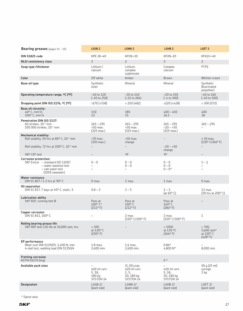
DIN 51825 code KPE 2K–40 KP2N–30 KP2N–20 KFK2U–40
NLGI consistency class 2 2 2 2
Soap type /thickener Lithium / Lithium Complex PTFE calcium complex calcium sulphonateColor Off white Amber Brown Whitish cream
Base oil type Synthetic Mineral Mineral Synthetic ester (fluorinated polyether)Operating temperature range, ºC (ºF) –40 to 120 –30 to 140 –20 to 150 –40 to 260 (–40 to 250) (–22 to 284) (–4 to 300) (–40 to 500)
Dropping point DIN ISO 2176, ºC (ºF) >170 (>338) > 250 (482) >220 (>428) > 300 (572)
Base oil viscosity: 40º C, mm2/s 110 185 400 – 450 400 100º C, mm2/s 13 15 26.5 38
Penetration DIN ISO 2137: 60 strokes, 10-1 mm 265 – 295 265 – 295 265 – 295 265 – 295 100 000 strokes, 10-1 mm +50 max. +50 max. –20 – +50 – (325 max.) (325 max.) (325 max.)Mechanical stability: Roll stability, 50 hrs at 80º C, 10-1 mm +70 max. +50 max. – ± 30 max. (350 max.) change (130° C/266° F) Roll stability, 72 hrs at 100º C, 10-1 mm – – –20 – +50 – change SKF V2F test – 'M' 'M' –Corrosion protection: SKF Emcor – standard ISO 11007 0 – 0 0 – 0 0 – 0 1 – 1 – water washout test – 0 – 0 0 – 0 – – salt water test – – 0 – 0* – (100% seawater)
Water resistance DIN 51 807 / 1.3 hrs at 90º C 0 max. 1 max. 1 max. 0 max.
Oil separation DIN 51 817, 7 days at 40º C, static, % 0.8 – 3 1 – 5 1 – 3 13 max. (at 60° C) (30 hrs at 200° C)Lubrication ability SKF R2F, running test B Pass at Pass at Pass at – 100° C* 100° C 140° C (212° F) (212° F) (284° F) Copper corrosion DIN 51 811, 100º C – 2 max. 2 max. 1 (150° C/300° F) (150° C/300° F) Rolling bearing grease life SKF R0F test L50 life at 10,000 rpm, hrs > 300 – > 1000 > 700, at 120º C at 130 ºC 5,600 rpm* (250º F) (266º F) at 220° C (428° F)EP performance Wear scar DIN 51350/5, 1,400 N, mm 1.8 max. 1.6 max. 0.86* – 4–ball test, welding load DIN 51350/4 2,600 min. 2,600 min. 4,800 N* 8,000 min.
Fretting corrosion ASTM D4170 (mg) 0 *
Available pack sizes – 35, 200 g tube – 50 g (25 ml) 420 ml cart. 420 ml cart. 420 ml cart. syringe 5, 18, 1, 5, 5, 18, 1 kg 180 kg 50, 180 kg 50, 180 kg SYSTEM 24 SYSTEM 24 SYSTEM 24
Designation LGGB 2/ LGWA 2/ LGHB 2/ LGET 2/ (pack size) (pack size) (pack size) (pack size)
Bearing greases (pages 11 - 15) LGGB 2 LGWA 2 LGHB 2 LGET 2

Lubricants
28
DIN 51825 code KPF2K–20 KPF2K–10 KP1G–30
NLGI consistency class 2 2 1
Soap type /thickener Lithium Lithium / Lithium calcium Color Black Black Brown
Base oil type Mineral Mineral Mineral Operating temperature range, ºC (ºF) –20 to 120 –10 to 120 –30 to 110 (–4 to 250) (14 to 250) (–22 to 230)
Dropping point DIN ISO 2176, ºC (ºF) >180 (356) >180 (356) >170 (338)
Base oil viscosity: 40º C, mm2/s 500 1020 200 100º C, mm2/s 32 58 16
Penetration DIN ISO 2137: 60 strokes, 10-1 mm 265 – 295 265 – 295 310 – 340 100 000 strokes, 10-1 mm 325 max. 325 max. +50 max. Mechanical stability: Roll stability, 50 hrs at 80º C, 10-1 mm 345 max. – – Roll stability, 72 hrs at 100º C, 10-1 mm – +50 max. – SKF V2F test 'M' 'M' –Corrosion protection: SKF Emcor – standard ISO 11007 0 – 0 0 – 0 0 – 0 – water washout test – 0 – 0* 0 – 0 – salt water test – 0 – 0* – (100% seawater)
Water resistance DIN 51 807 / 1.3 hrs at 90º C 1 max. 1 max. 1 max.
Oil separation DIN 51 817, 7 days at 40º C, static, % 1 – 5 1 – 5 8 – 13
Lubrication ability SKF R2F, running test B Pass at – – 100° C (212° F)Copper corrosion DIN 51 811, 100º C 2 max. 1 max. 2 max. (90° C/194° F)Rolling bearing grease life SKF R0F test L50 life at 10,000 rpm, hrs – – – EP performance Wear scar DIN 51350/5, 1,400 N, mm 1.4 max. 1.2 max. 1.8 max. 4–ball test, welding load DIN 51350/4 3,000 min. 3,000 min. 3,200 min.*
Fretting corrosion ASTM D4170 (mg) 5.5 *
Available pack sizes – 35 g tube – 420 ml cart. 420 ml cart. 420 ml cart. 5, 18, 5, 18, 5, 50, 180 kg 180 kg 50, 180 kg SYSTEM 24
Designation LGEM 2/ LGEV 2/ LGWM 1/ (pack size) (pack size) (pack size)
Bearing greases (pages 11 - 15) LGEM 2 LGEV 2 LGWM 1

29
Manual lubrication Grease packer LAGP 400 30
Bearing packer VKN 550 30
Grease guns 1077600 and LAGH 400 31
Battery-driven grease gun LAGG 400B 32
Piston pump with block feeder PF-VPBM 33
Grease meter LAGM 1000E 34
Technical data 35

30
Manual lubrication
Grease packer LAGP 400To lubricate open bearings
The grease packer LAGP 400 is a low–pressure alternative for emptying SKF grease cartridges. It provides an easy and clean alternative to manual grease packing of open bearings.
• Supplied with three spout caps• Applies grease to open bearings or
open gears
Bearing packer VKN 550Contamination-free grease filling
The SKF bearing packer, VKN 550, is a sturdy, easy–to–use, efficient and effective bearing grease packer. It can also be used in combination with a standard grease gun, air–operated grease pump or grease filler pump. Although specially designed for taper roller bearings, the SKF bearing packer works for any type of open bearing which needs to be 100% pre–filled with grease.
• Flushes the grease between the rolling elements where it matters most, prolonging the bearing service life
• Closed system and the cover lid prevent ingress of dirt, virtually eliminating contamination
• Allows the operator to pre–fill bearings with grease in a quick and clean way
• Prevents unnecessary grease loss• Economical and environmentally
friendly
31
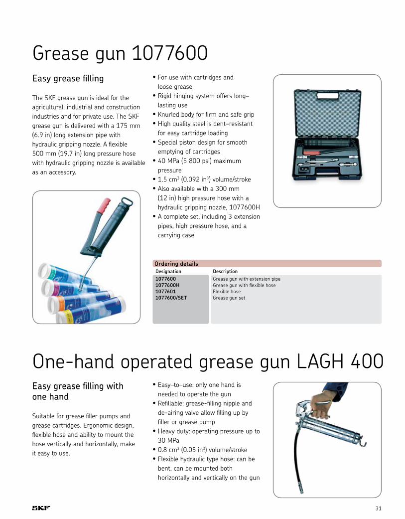
Grease gun 1077600Easy grease filling
The SKF grease gun is ideal for the agricultural, industrial and construction industries and for private use. The SKF grease gun is delivered with a 175 mm (6.9 in) long extension pipe with hydraulic gripping nozzle. A flexible 500 mm (19.7 in) long pressure hose with hydraulic gripping nozzle is available as an accessory.
• For use with cartridges and loose grease
• Rigid hinging system offers long– lasting use
• Knurled body for firm and safe grip• High quality steel is dent–resistant
for easy cartridge loading• Special piston design for smooth
emptying of cartridges• 40 MPa (5 800 psi) maximum
pressure• 1.5 cm3 (0.092 in3) volume/stroke• Also available with a 300 mm
(12 in) high pressure hose with a hydraulic gripping nozzle, 1077600H
• A complete set, including 3 extension pipes, high pressure hose, and a carrying case
Ordering detailsDesignation Description1077600 Grease gun with extension pipe 1077600H Grease gun with flexible hose 1077601 Flexible hose 1077600/SET Grease gun set
One-hand operated grease gun LAGH 400Easy grease filling with one hand
Suitable for grease filler pumps and grease cartridges. Ergonomic design, flexible hose and ability to mount the hose vertically and horizontally, make it easy to use.
• Easy–to–use: only one hand is needed to operate the gun
• Refillable: grease-filling nipple and de-airing valve allow filling up by filler or grease pump
• Heavy duty: operating pressure up to 30 MPa
• 0.8 cm3 (0.05 in3) volume/stroke• Flexible hydraulic type hose: can be
bent, can be mounted both horizontally and vertically on the gun

32
Manual lubrication
Battery-driven grease gun LAGG 400BQuick and easy grease filling
The battery-driven grease gun LAGG 400B is a high quality grease gun suitable for lubricating bearings, machines, vehicles and other applications. Ergonomically designed and user-friendly, the grease gun can be used with standard SKF grease cartridges (420 ml) or filled with approximately 500 cm3 (17 fl. oz.) of loose grease.
• Compared to hand operated grease guns, a 420 ml cartridge can be emptied in approximately 10 minutes with minimum effort, resulting in significant cost and time savings
• Electrical operation and the ergonomic design of the hand grip helps reduce operator fatigue compared to manual methods
• Easy-to-use one hand operation makes the grease gun user-friendly
• Supplied with various electrical plugs and two power supply versions (230 and 110 V charger) makes it operational worldwide
• Battery operation allows use in almost all environments without use of a main electrical supply
• Long battery life (1,000 charging cycles) helps reduce product life costs
• Refillable: grease filling nipple and de-airing valve allow filling up by filler or grease pump
• Safety valve setting set to 40 MPa (5,800 psi) helps increase operator safety
• Supplied with M10x1 nozzle, interchangeable with SKF hoses, SKF grease meter LAGM 1000E and other accessories
Designation DescriptionLAGG 400B-1 High pressure hose 750 mm (29.5 in.) with gripping nozzle LAGG 400B-2 Battery pack
Replacement parts

33
Piston pump with block feeder PF-VPBMManually operated
The piston pumps with a block feeder are used on farm machinery, small stackers and construction machinery as well as motor vehicle superstructures. The piston pump has 6 to 12 lubricant outlets depending on the block feeder. Every stroke of the lever delivers 2 cm3 of lubricant to the feeder. Also available without block feeder with only one M10 x 1 outlet on the front (order no. VGBL 169-000-146). The level of the lubricant in the cartridge can be checked by pulling out the cartridge until distinct resistance is felt. When the cartridge is full, the piston rod can be pulled out approximately 415 mm.
Pay attention to cleanliness when changing cartridges, and proceed as follows:1. Open the toggle-type fastener 2. Unscrew the gun tube 3. Pull piston rod out to the stop 4. Change the cartridge
5. Screw in the gun tube 6. Close the toggle-type fastener 7. Loosen the lock, push in the piston
rod up to the stop8. Actuate the vent valve until grease
emerges
Ordering details
Progressive feeder Number of Number of outlet pairs maximum (pistons) outlets
VGAB VPBM-3 3 6 VGAB VPBM-4 4 8 VGAB VPBM-5 5 10 VGAB VPBM-6 6 12
Ordering details
Complete unit Number of outlets VGBL PF-VPBM-3-2 6 VGBL PF-VPBM-4-2 8 VGBL PF-VPBM-5-2 10 VGBL PF-VPBM-6-2 12 VGBL 169-000-146 1 (Gun only)
See Accessories chapter for tubing, fittings and connectors.See Lubricants chapter for grease cartridges.
Function diagram
Lubricantinlet
plug 917-006-101(hexagon socket SW 3)
screw plug incl. O-ring466-431-001
34
Manual lubrication
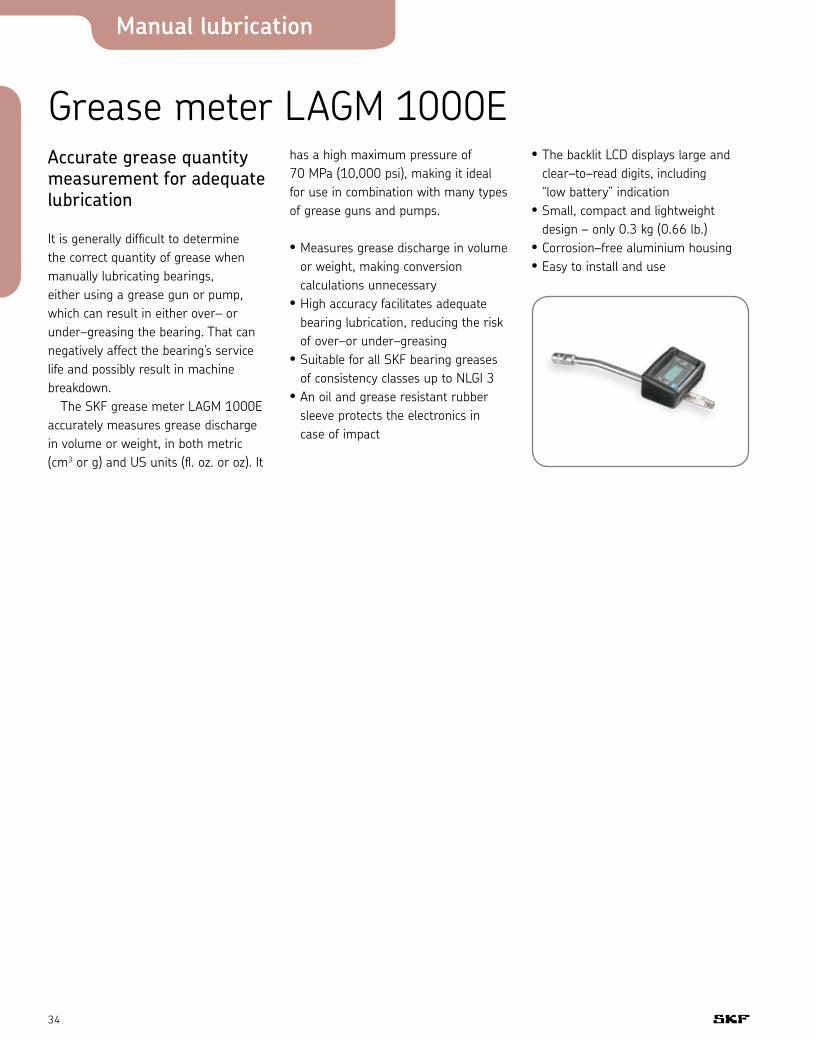
Grease meter LAGM 1000EAccurate grease quantity measurement for adequate lubrication
It is generally difficult to determine the correct quantity of grease when manually lubricating bearings, either using a grease gun or pump, which can result in either over– or under–greasing the bearing. That can negatively affect the bearing’s service life and possibly result in machine breakdown. The SKF grease meter LAGM 1000E accurately measures grease discharge in volume or weight, in both metric (cm3 or g) and US units (fl. oz. or oz). It
has a high maximum pressure of 70 MPa (10,000 psi), making it ideal for use in combination with many types of grease guns and pumps.
• Measures grease discharge in volume or weight, making conversion calculations unnecessary
• High accuracy facilitates adequate bearing lubrication, reducing the risk of over–or under–greasing
• Suitable for all SKF bearing greases of consistency classes up to NLGI 3
• An oil and grease resistant rubber sleeve protects the electronics in case of impact
• The backlit LCD displays large and clear–to–read digits, including “low battery” indication
• Small, compact and lightweight design – only 0.3 kg (0.66 lb.)
• Corrosion–free aluminium housing• Easy to install and use
35
Technical dataDesignation LAGP 400Maximum volume per stroke 20 cm3 (1.2 in3) Material Steel and polyethylene
LAGP 400 (page 30)
Length 360 mm (14 in) Weight 0.35 kg (0.77 lb.)
Designation 1077600Maximum pressure 40 MPa (5 800 psi) Volume/stroke 1.5 cm3 (0.09 in3)
1077600 (page 31)
Length 380 mm (14.9 in) Weight 1.5 kg (3.3 lb.)
Designation LAGH 400Maximum pressure 30 MPa (4 350 psi) Volume/stroke approx. 0.8 cm3 (0.049 in3)
LAGH 400 (page 31)
Length 370 mm (14.6 in) Weight 1.5 kg (3.3 lb.)
Designation VKN 550Description Bearing grease packer Weight 1.8 kg (3.9 lb.) Material Zinc plated, metal finish Suitable greases Approved for all SKF greases
VKN 550 (page 30)
Other greases NLGI class 000 to 2 Bearing range – Inner diameter d 19 to 120 mm – Outer diameter D Max 200 mm
Designation DescriptionLAGG 400B Battery driven grease gun (with 230 V charger) LAGG 400B/US Battery driven grease gun (with 110 V charger) Maximum operating pressure 40 MPa (5 800 psi) Min. burst pressure pump 80 MPa (11 600 psi) Grease nozzle 4 jaws (suitable for nipples according to DIN 71412) Operating temperature range -15° to +50° C (5° to 120° F) Grease NLGI NLGI 000 to NLGI 2
Weight/dimensions:
Dimensions of grease gun including battery (L x H x D) 410 x 230 x 80 mm (16.2 x 9 x 3.2 in) Weight of grease gun (including battery) 3.1 kg (6.8 lbs.) Dimensions of carrying case (W x D x H) 480 x 390 x 130 mm (18.9 x 15.3 x 5.1 in) Total weight (including case) 5.4 kg (11.9 lbs.)
LAGG 400B (page 32)
36
Manual lubrication
Designation LAGM 1000EHousing material Aluminium, anodized Weight 0.3 kg (0.66 lb.) IP rating IP 67 Suitable greases NLGI 0 – NLGI 3 Maximum operating pressure 70 MPa (10,000 psi) Maximum grease flow 1 000 cm3/min (34 fl. oz./min) Thread connections M10 × 1 Display Lit LCD (4 digits / 9 mm)
LAGM 1000E (page 34)
Accuracy ±3% from 0 – 300 bar ±5% from 300 – 700 bar Selectable units cm3, g, fl. oz. or oz. Display lamp auto switch off 15 seconds after last pulse Low battery Indication on display Battery type 1.5 V LR1 (2×) Alkaline Unit auto switch off 1 minute after last pulse
Designation PF-VPBMLubricant Grease up to NLGI grade 2 Reservoir capacity 450 ccm in 400 g cartridge G or W DIN 1284 Temperature range -25° to +80° C (-13° to +176° F) Mounting position Any position Delivery rate 2 ccm per stroke Maximum back pressure 400 bars
PF-VPBM (page 33)

37
Automatic lubricators SYSTEM 24® single–point automatic lubricator LAGD 125 and 60 38
SYSTEM 24® single–point automatic lubricator LAGE 125 and 250 40
Relubrication calculation program DialSet® 4.0 43
SYSTEM MultiPoint automatic lubricator LAGD 400 44
Oil leveller LAHD 500 and 1000 45
Compact greaser 46
Technical data 48

Automatic lubricators
38
Single–point automatic lubricators LAGD 125 and 60
Poor lubrication can considerably reduce the service life of the best of bearings. With that in mind, SKF has enhanced the performance of the single–point automatic lubricator.
Product enhancements Increased reliability at high temperatures are a result of:• Transparent lubricant container made
of polyamide reduces gas diffusion• The larger molecules of the driving
inert gas are less sensitive to higher temperatures
Intrinsically safe approval for Zone 0• Tested and approved for use in areas
where an explosive atmosphere caused by gases, vapors and dust, is continuously present as well as for use in mines and underground areas
Easy–to–remove end–cap• Covers the lubricant outlet; sharp
tools are no longer required to open the outlet
Easy installation• The tool–free activation and time-
setting slot allows easy and accurate adjustment of lubrication flow
Easy and quick fitting• Facilitated by easy–grip top cover
While enhancing the reliability and ease–of–use, SYSTEM 24 still offers you the features and benefits you have to come to expect from SKF automatic lubricators.
Existing features• Flexible time setting period ranging
from 1 and 12 months• High reliability and dispense rate
accuracy allow fit and forget procedure until predetermined replacement date
• Transparent lubricant container allows visual inspection of dispense rate
• High capacity, compact size permits installation in restricted areas
• Redesigned non–return valve of the oil–filled SYSTEM 24 is less sensitive to vibration, minimizing the risk of leakage
• Available filled with various high quality SKF greases and oils, which are especially developed for a wide range of bearing applications
More reliable and easier to use SYSTEM 24®

39
• Dispense rate setting is a simple part of the installation process
• Hermetic sealing prevents ingress of dirt or foreign matter
• Allows low grease dispense rate• Available in two sizes: 125 ml
(LAGD 125) and 60 ml (LAGD 60)• Can be temporarily deactivated• Wide range of accessories is available• II 1GD EEx ia IIC T6 T85° C
I M1 EEx ia I EC Type Examination Certificate Kema04ATEX1275X
SKF single-point automatic lubricators LAGD 125 and LAGD 60
Ordering detailsDesignation DescriptionLAGD 125/WA2 125 ml (4.25 fl. oz.) unit filled with LGWA 2 grease - wide application, general purpose LAGD 60/WA2 60 ml (2.03 fl. oz.) unit filled with LGWA 2 grease - wide application, general purpose LAGD 125/EM2 125 ml (4.25 fl. oz.) unit filled with LGEM 2 grease - electric motor LAGD 125/FP2 125 ml (4.25 fl. oz.) unit filled with LGFP 2 grease - food processing LAGD 125/GB2 125 ml (4.25 fl. oz.) unit filled with LGGB 2 grease - green biodegradable LAGD 125/HB2 125 ml (4.25 fl. oz.) unit filled with LGHB 2 grease - high loads LAGD 125/HP2 125 ml (4.25 fl. oz.) unit filled with LGHP 2 grease - quiet running, high speeds
LAGD 125/HFP15* 125 ml (4.25 fl. oz.) unit filled with food processing oil (viscosity ISO 150) LAGD 125/HHT26* 125 ml (4.25 fl. oz.) unit filled with synthetic high temperature chain oil (viscosity ISO 265) LAGD 125/HMT68* 125 ml (4.25 fl. oz.) unit filled with mineral EP type chain oil (viscosity ISO 68) LAGD 60/HMT68* 60 ml (2.03 fl. oz.) unit filled with mineral EP type chain oil (viscosity ISO 68) LAGD 125/U* 125 ml (4.25 fl. oz.) empty unit suitable for oil filling
* Includes non–return valve
On/off knob and time setting dial Enables easy activation and dial setting
LED status indicators Helps verify operating status
Drive cover Easily removable, seals and helps prevent ingress of dirt and moisture
Electric motor and gearbox Helps enable constant discharge pressure
Battery pack
Piston Special piston shape helps ensure optimum emptying of lubricator
Spindle Rotates to drive piston, enabling lubricant to be dispensed
Lubricator canister Filled with high quality SKF lubricant
Anti-vacuum membrane Helps prevent vacuum forming
A BB
CC
DD
E
E
F
F
GG
HH
I
I
J
J
A

Automatic lubricators
40
Single–point automatic lubricators LAGE 125 and 250
The LAGE series of the SKF System 24 family are single point electro mechanical driven automatic lubricator systems. Suitable for a wide range of applications and operating conditions, the units are reliable and flexible in operation. Supplied ready to use straight from the box and ease of installation make the units a perfect compliment to the comprehensive range of SKF automatic lubricators.
Existing features• Electro mechanical driven makes the
unit high reliable in operation• Available in two sizes: 122 ml (LAGE
125) and 250 ml (LAGE 250) to suit most bearing lubrication applications
• Remote mounting up to 3 meters (10 ft) for grease filled units and 5 meters (15 ft) for oil filled units allows lubrication of bearings in areas with high ambient temperatures, excessive vibration or hazardous environments
• Available filled with various high quality SKF greases and oils, to suit a wide range of bearing applications
• Refill sets consisting of a canister filled with SKF grease or oil and a battery pack help ensure reliable lubricator operation
• Flexible user adjustable dispense settings of 1, 3, 6, 9, or 12 months for use in many different applications
• Ingress protection to 65 IP level allows the lubricator to used in many dusty and wet environments
• Temperature independent dispense rate, suitable for us in applications with changing temperatures
• Unlike gas powered units, a maximum discharge pressure of 6 bar can be achieved over the whole lubicant dispensing period
• Easy activation using a clearly marked dial helps minimize setting errors
• Transparent lubricant container allows visual inspection of dispense rate, while electro mechanical functions are indicated by simple red-green LED indicators
• Intrinsic safety rating: UL listed• Wide range of accessories is available• SKF system 24 LAGE series is fully
featured in SKF DialSet 4.0
Reliable, reusable lubricator system meets many needs

41
LAGE 125/WA2 LGWA 2 Multi-purpose EP type grease Complete unit 125 LAGE 250/WA2 Complete unit 250 LGWA 2/EML125 Refill set 125 LGWA 2/EML250 Refill set 250
LAGE 125/EM2 LGEM 2 High loads, slow rotations Complete unit 125 LAGE 250/EM2 Complete unit 250 LGEM 2/EML125 Refill set 125 LGEM 2/EML250 Refill set 250
LAGE 125/HB2 LGHB 2 High temperature, loads, plain bearing Complete unit 125 LAGE 250/HB2 Complete unit 250 LGHB 2/EML125 Refill set 125 LGHB 2/EML250 Refill set 250
LAGE 125/HP2 LGHP 2 High performance polyurea Complete unit 125 LAGE 250/HP2 Complete unit 250 LGHP 2/EML125 Refill set 125 LGHP 2/EML250 Refill set 250
LAGE 125/FP2 LGFP 2 Food processing industry Complete unit 125 LAGE 250/FP2 Complete unit 250 LGFP 2/EML125 Refill set 125 LGFP 2/EML250 Refill set 250
Oils
LAGE 125/HMT68 LHMT 68 Medium temperature oil Complete unit 125 LAGE 250/HMT68 Complete unit 250 LHMT 68/EML125 Refill set 125 LHMT 68/EML250 Refill set 250
LAGE 125/HHT26 LHHT 265 High temperature oil Complete unit 125 LAGE 250/HHT26 Complete unit 250 LHHT 265/EML12 Refill set 125 LHHT 265/EML25 Refill set 250
LAGE 125/HFP15 LHFP 150 Food compatible, NSF H1 approved oil Complete unit 125 LAGE 250/HFP15 Complete unit 250 LHFP 150/EML12 Refill set 125 LHFP 150/EML25 Refill set 250
Ordering detailsDesignation Lubricant Description Product Greases
On/off knob and time setting dial Enables easy activation and dial setting
LED status indicators Helps verify operating status
Drive cover Easily removable, seals and helps prevent ingress of dirt and moisture
Electric motor and gearbox Helps enable constant discharge pressure
Battery pack
Piston Special piston shape helps ensure optimum emptying of lubricator
Spindle Rotates to drive piston, enabling lubricant to be dispensed
Lubricator canister Filled with high quality SKF lubricant
Anti-vacuum membrane Helps prevent vacuum forming
A BB
CC
DD
E
E
F
F
GG
HH
I
I
J
J
A

Automatic lubricators
42
Accessories ordering detailsDesignation DescriptionLAPA 45 Angle connection 45° LAPA 90 Angle connection 90° LAPB 3x4E1* Brush 30 × 40 mm LAPB 3x7E1* Brush 30 × 60 mm LAPB 3x10E1* Brush 30 × 100 mm LAPB 5-16E* Elevator brush, 5 – 16 mm gap LAPB D2* Brush round Ø 20 mm LAPC 50 Clamp LAPE 35 Extension 35 mm LAPE 50 Extension 50 mm LAPT 1000 Flexible tube, 1 000 mm long, 8 × 6 mm LAPF F1/4 Tube connection female G 1/4 LAPF M1/4 Tube connection male G 1/4 LAPF M1/8 Tube connection male G 1/8 LAPF M3/8 Tube connection male G 3/8 LAPG 1/4 Grease nipple G 1/4
Designation DescriptionLAPM 2 Y–connection LAPM 4 Manifold (4 to 1) LAPN 1/8 Nipple G 1/4 – G 1/8 LAPN 1/2 Nipple G 1/4 – G 1/2 LAPN1/4 Nipple G 1/4 – G 1/4 LAPN 3/8 Nipple G 1/4 – G 3/8 LAPN 6 Nipple G 1/4 – M6 LAPN 8 Nipple G 1/4 – M8 × 1.25 LAPN 8x1 Nipple G 1/4 – M8 × 1 LAPN 10 Nipple G 1/4 – M10 × 1.5 LAPN 10x1 Nipple G 1/4 – M10 × 1 LAPN 12 Nipple G 1/4 – M12 LAPN 12x1.5 Nipple G 1/4 – M12 × 1.5 LAPP 2E Protection base LAPP 3E Protection cover LAPV 1/4 Non return valve G 1/4 LAPV 1/8 Non return valve G 1/8
* Suitable for use with oil filled SYSTEM 24 units only
43
Accurate calculation of relubrication intervals
DialSet® is a calculation program, which easily calculates the correct relubrication intervals settings. After selecting the criteria and grease relevant to your application, the program provides you with the correct settings for your SKF automatic lubricators.
• Selecting the operating conditions of your application, vertical shaft, outer ring rotation and shock loads, allows accurate calculation of the relubrication intervals
• Calculations are based on SKF lubrication theories
• Calculated lubrication interval depends on the properties of the selected grease, minimizing the risk of under- or over–lubrication and optimizing grease consumption
• Calculations are based on SKF automatic lubrication systems grease dispense rates, allowing the recommendation of the correct lubricator setting
• Recommended grease quantity depends on the grease replenishment position; side or W33 for optimum grease consumption
• Includes a complete list of the SKF SYSTEM 24 family accessories
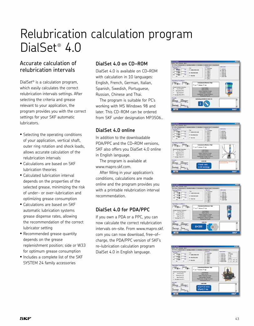
DialSet 4.0 on CD–ROMDialSet 4.0 is available on CD–ROM with calculation in 10 languages: English, French, German, Italian, Spanish, Swedish, Portuguese, Russian, Chinese and Thai. The program is suitable for PC’s working with MS Windows 98 and later. This CD-ROM can be ordered from SKF under designation MP3506..
DialSet 4.0 onlineIn addition to the downloadable PDA/PPC and the CD–ROM versions, SKF also offers you DialSet 4.0 online in English language. The program is available at www.mapro.skf.com. After filling in your application’s conditions, calculations are made online and the program provides you with a printable relubrication interval recommendation.
DialSet 4.0 for PDA/PPCIf you own a PDA or a PPC, you can now calculate the correct relubrication intervals on–site. From www.mapro.skf.com you can now download, free–of–charge, the PDA/PPC version of SKF’s re–lubrication calculation program DialSet 4.0 in English language.
Relubrication calculation program DialSet® 4.0

Automatic lubricators
44
Multiple grease lubrication points made easy
The lubrication of bearings with the correct type and quantity of grease is essential for trouble–free operation. Research has shown that 36% of all bearings fail prematurely due to incorrect lubrication. Especially for
installations with multiple lubrication points, this can be a time–consuming and costly process. SYSTEM MultiPoint, SKF’s centralized automatic lubricator, is the most user–friendly and cost–effective automatic lubricator for multiple grease lubrication points available today. Its compact design, combined with electronically controlled
SYSTEM MultiPoint automatic lubricator LAGD 400
accuracy, makes it an excellent solution for longer bearing life and increased uptime of your machinery.
• Do–it–yourself centralized lubrication system
• Up to 8 feed lines• Easy–to–use• DialSet 4.0 included: SKF’s
re–lubrication calculation program allows accurate calculation of the correct re–lubrication intervals
• Long feed lines (maximum up to 5 m / 16 ft)
• Electronic setting and read–out of control parameters
• Alarm function for blocked feed lines and empty cartridge
• Machine steering (i.e. lubricator only operates while machine is running)
• High–pressure capability (40 bar / 600 psi)
• Tested and approved with all SKF greases
• Uses standard SKF grease cartridges (420 ml)
• Ready for use, all accessories included
45
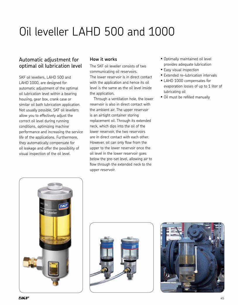
Automatic adjustment for optimal oil lubrication level
SKF oil levellers, LAHD 500 and LAHD 1000, are designed for automatic adjustment of the optimal oil lubrication level within a bearing housing, gear box, crank case or similar oil bath lubrication application. Not usually possible, SKF oil levellers allow you to effectively adjust the correct oil level during running conditions, optimizing machine performance and increasing the service life of the applications. Furthermore, they automatically compensate for oil leakage and offer the possibility of visual inspection of the oil level.
How it worksThe SKF oil leveller consists of two communicating oil reservoirs. The lower reservoir is in direct contact with the application and hence its oil level is the same as the oil level inside the application. Through a ventilation hole, the lower reservoir is also in direct contact with the ambient air. The upper reservoir is an airtight container storing replacement oil. Through its extended neck, which dips into the oil of the lower reservoir, the two reservoirs are in direct contact with each other. However, oil can only flow from the upper to the lower reservoir once the oil level in the lower reservoir goes below the pre–set level, allowing air to flow through the extended neck to the upper reservoir.
• Optimally maintained oil level provides adequate lubrication
• Easy visual inspection • Extended re–lubrication intervals • LAHD 1000 compensates for
evaporation losses of up to 1 liter of lubricating oil
• Oil must be refilled manually
Oil leveller LAHD 500 and 1000

Automatic lubricators
46
Compact greaserInnovation for linear guides
Compact greaser for linear guide systems• Up to 5 lubricant outlet ports• Suitable for grease,
NLGI grades 000 to 2• Increases the service life of linear
guides• Increases operating reliability• Cuts maintenance and service costs
Compact, automatic, dependable With our compact greaser we have succeeded in developing an automatic, electrically driven centralized lubrication system especially designed for linear guide systems. The ETP compact greaser does not require a separate control unit. The machine’s control system provides the electric power and control functions. Unlike Permadose dispensers, the compact greaser lubricates only when the machine is running. The compact greaser is easy to install due to its small dimensions and low weight. With its bayonet holder, it’s also easy to change the reservoir whenever necessary. Depending on lubricant consumption, the grease could last for up to five years of operation.
Ordering detailsOrder no. Number of Outlet Metering (mm3) outlets assignment outlet no. 1 2 3 4 5
VGPG ETP2 2 1 and 3 15 X 15 X X
VGPG ETP3 3 1, 3 and 4 15 X 15 15 X
VGPG ETP4 4 1 to 4 15 15 15 15 X
VGPG ETP5 5 1 to 5 15 15 15 15 15

47
Compact greaser ETP
Accessories (to be ordered separately)
PA tube, 1.5 m with socket union on one side, filled with grease
Order no. VGKG 995-001-197+BF5
Socket union, order no. VGKG 402-612
Tapered sleeve, order no. VGKG 402-611
Reinforced socket, order no. VGKG 402-603
Adaptors for 2.5 mm diam. tube: M6 Order no. VGKG 402-004 M6 x 0.75 Order no. VGKG 402-003
M8 x 1 Order no. VGKG 402-006
1) Ports tapped for solderless connection pipe Ø 2.5 mm

Automatic lubricators
48
LAGD 125 and 60 (page 38)
Grease capacity LAGD 125 125 ml (4.25 fl. oz.) LAGD 60 60 ml (2.03 fl. oz.)
Nominal emptying time Adjustable; 1 – 12 months Ambient temperature range –20° to 60º C (–5° to 140º F) Maximum operating pressure 5 bar (75 psi) Drive mechanism Gas cell producing inert gas Connection thread G 1/4
Maximum feed line length with: – grease 300 mm (11.8 in) – oil 1 500 mm (59.1 in)
Intrinsically safe approval II 1GD EEx ia IIC T6 T85° C I M1 EEx ia I EC Type Examination Certificate Kema04ATEX1275X Protection class IP 68 Recommended storage temperature 20º C (70º F) Storage life of lubricator 2 years Weight LAGD 125 approx 200 g (7.1 oz.) LAGD 60 approx 130 g (4.6 oz.) Lubricant included
Designation LAGD 400Content 8–outlet lubricator 20 m tubing Quick connectors for application side 2 Y–connectors LGMT 2 / 0.4 grease cartridge SKF's DialSet program Number of feed-lines 1 – 8 Maximum pressure 40 bar (600 psi) Suitable grease NLGI 1, 2 and 3 Maximum length of feed lines 5 m (16 ft.) Ambient temperature 0° – 50° C (32° – 120° F) Drive mechanism Electro–mechanical
LAGD 400 (page 44)
Volume 0.1 – 10 cm3/day (0.003 – 0.35 fl. oz./day) Per outlet Approximately 0.6 – 65 g/week (0.02 – 2.3 oz./week) Power 110–240V AC, 50–60Hz or 24V DC Alarms Blocked feed lines, empty cartridge; Internal and external External steering External relay steering IP rating 54 Lubrication tubes 20 m (65 ft.), Nylon, 6 × 1.5 mm (1/4 × 0.06 in) Connection thread G 1/4 Height 530 mm (21 in)
Technical data
Grease capacity LAGE 125 122 ml (4.1 fl. oz US) LAGE 250 250 ml (8.5 fl. oz US)Emptying time User adjustable: 1, 3, 6, 9 and 12 months Lowest grease purge – LAGE 125 0.3 ml per day (0,01 fl. oz US) – LAGE 250 0.7 ml per day (0,02 fl. oz US) Highest grease purge – LAGE 125 4.1 ml per day (0,13 fl. oz US) – LAGE 250 8.3 ml per day (0,28 fl. oz US) Ambient temperature range 0 °C (-10°C peak ) to 50 °C (32 °F (14 °F peak) to 122 °F) Maximum operating pressure 5 bar (75 psi) Drive mechanism Electro–mechanical Connection thread R ¼ Maximum feed line length with: – grease Up to 3 meters (10 ft) * – oil Up to 5 meters (16 ft) LED status indicators operating, purging lubricant, empty, malfunction
LAGE 125 and 250 (page 40 – 41)
Intrinsic safety rating UL listed T code 59°C - Category BAYZ – 92UM Lubricant dispensing equipment for use in hazardous locations Class I, Division II, Group A, B, C, D Class II, Division II, Group F &G Class III Protection class assembled lubricator IP 65 Battery pack 4,5V 2,7 Ah - Alkaline manganese Recommended storage temperature 20 °C (70 °F) Storage life of lubricator 3 years ** (2 years for LGFP 2 and Oils) Total weight
– LAGE 125 635 g (22,5 oz) 635 g (22,5 oz) – LAGE 250 800 g (28,2 oz) 800 g (28,2 oz)
* The maximum feed line length is dependent on ambient temperature, grease type and back pressure created by the application.
** Storage life is 3 years from production date, which is printed on the side of the canister. The canister and battery pack may be used even at 12 months setting if acti-vated 3 years from production date.

49
Designation LAHD 500 / LAHD 1000Boundary dimensions – LAHD 500 Ø 91 mm × 290 mm high (3.6 × 11.4 in) – LAHD 1000 Ø 122 mm × 290 mm high (4.8 × 11.4 in) Reservoir volume – LAHD 500 500 ml (17 fl. oz.) – LAHD 1000 1 000 ml (34 fl. oz.) Container material Polycarbonate / aluminium Allowed temperature range – 20° to 125˚ C (–4° to 255˚ F)
LAHD 500 and 1000 (page 45)
Permissible humidity 0 – 100% Length of connecting tube 600 mm (23.5 in) Connection thread G 1/2 Tube material Polyurethane O–ring material NBR – 70 shore Gaskets NBR – 80 shore 6 pieces Other material Aluminum, bronze, stainless steel Suitable oil types Mineral and synthetic oils
Compact greaser (page 46)
Number of outlet ports 2, 3, 4, or 5 Operating pressure 6 bars Power 24 V DC Actuation duration 7 min Pause interval minimum 30 min Power consumption 24 W
Starting current maximum 1 A Operating temperature 15° to 40° C (59° to 104° F) El. connection DIN EN 175301-803 Reservoir 80 cm3 cartridge Lubricant Grease, NLGI grade 000 to 2
Automatic lubricators
50

51
Pre-engineeredsystems
Fan and industrial application units: grease 52
SYSTEM MultiPoint automatic lubricator LAGD 1000 53
Mini-pump units 54
Battery-powered piston pump 55
Grease injectors VL-1, VL-11 and VL-32 56
VSP Modular progressive feeders 58
DuoflexTM lubricant distributor 60
Fan and industrial application units: oil 61
Single-circuit pumps 64
SafeflowTM oil flowmeters 66
Level switches 67
Tabletop chain lubrication systems 70
Compact units for oil 72
Piston distributors 73
Flow monitors and sensors for oil 76
Technical data 78

Pre-engineered systems
52
Fan and industrial application units: greaseFan units – grease
SKF has taken the knowledge and expertise of Vogel Lubrication and developed three solutions for grease-lubricated fan and blower bearings. Fan and blower bearings are often critical to the operation of industrial manufacturing facilities. In some cases, they are in hard-to-access locations. The SKF grease lubrication units for fans can help users ensure that these bearings are being lubricated properly. These units are designed to deliver grease from 2 to 20 points consistently and effectively, providing the right amount of lubrication for extended bearing life.
Applications• Industrial fans• Blowers• Motors• Pumps
Features• Durable construction• Easy installation• Highly effective lubrication
monitoring with indicator pins on each metering chamber
• Simple monitoring of system pressure with switch at end of line
Ordering detailsPart no. Reservoir capacity Pressure Nylon tubing (Liters) Low level switch gauge Filter Controls Monitoring Enclosure installation kit
VGPA KFGS10-5W1-XX-V6 2 • • • • • •VGPA KFGS10-5W1-XX-V8 2 • • • • •VGPA KFGS10-5W1-XX-V32 2 • • • • • •VGPA KFGS10-5W1-XX-V33 2 • • • • • • •
VGPA KFGS30-5W1-XX-V6 6 • • • • • •VGPA KFGS30-5W1-XX-V8 6 • • • • •VGPA KFGS30-5W1-XX-V32 6 • • • • • •VGPA KFGS30-5W1-XX-V33 6 • • • • • • •
VGPA KFGS10-5W1-20-V33
VGPA KFGS10-5W1-02-V6 VGPA KFGS30-5W1-02-V6
XX = the number of points required. When ordering, specify the number of points (02-20). Example: VGPA KFGS10-5W1-02-V8 • = components contained in the unit
• Fully-automated operation with use of electronic control system
• Central monitoring of feeder points possible with progressive feeder cycle sensor
• 6 mm secondary lines avoid increased pressure of overall system
• Built in reservoir agitation prevents grease separation and eliminates entrained air in the system
• 96-264VAC, 50/60 Hz, 12 or 24 VDC available upon request

53
SYSTEM MultiPoint automatic lubricator LAGD 1000Centralized lubrication for up to 20 lubrication points
The SKF SYSTEM MultiPoint automatic lubricator LAGD 1000 is a reliable centralized lubrication system offering lubrication solutions for bearings and machinery. The LAGD 1000 uses a high-pressure pump and a progressive feeder for lubricating from 6 to 20 lubrication points. Supplied as a complete ready-to-use kit, all accessories required are included in the box.
• Suitable for greases from NLGI 000 to NLGI 2, offers high flexibility in types of lubricants that can be used
• Sturdy, robust design with IP65 rating, suitable for most industrial environments
• Transparent reservoir, allows visual monitoring of lubricant level
• Progressive divider so that exactly the same amount of grease reaches each lubrication point
• 1 liter (33.8 fl. oz.) refillable grease container, increases intervals between refilling
• Extensive programming options, allowing flexibility to suit most applications
• Empty container alarm, helps reduce the risks associated with lack of lubrication
• Wide temperature range, helps meet a variety of tough operating conditions year round
• Cycle switch function (not on battery version) notifies operator of blocked outlets so that proper action can be taken
• Battery powered version available, no need for external power source, can be used most anywhere
Note: To order, specify power source and number of points. Examples: LAGD 1000 / B12 Battery powered LAGD 1000 / DC12 24V DC LAGD 1000 / AC12 110-240V AC

Pre-engineered systems
54
Mini-pump units, group KFA/KFASPumps belonging to the KFA(S) series come with a maximum of 2 outlet ports for the connection of 2 independent lube circuits. A separate pump element is required for each outlet. Three pump elements with different delivery rates are available so that the volume of grease can be adjusted to the needs of the individual circuits. This feature ensures that every lube point is supplied with an adequate amount of grease in each lubrication cycle. Control is provided by an integral IG502-I control and monitoring unit; it can be operated in a time- or load- (pulse) dependent mode, and with or without monitoring.
The control system provides the following advantages:• Non-volatile memory with
PIN-code protection• Storage of residual interval and
lubricating cycle• Storage of fault signals
(diagnosis memory)• Data save in event of a power failure• Connection for external pushbutton• Connection for inductive cycle switch• Interval and contact times can be set
independent of each other, even with monitored systems
• Electrical connections easy via 7-pole plug connector
Please order cable harness separately. Contact SKF for ordering information.
Ordering detailsPiston pump Reservoir capacity Grease fillingOrder no. (liters) including grease
VGBB KFA1 1 Via conical head nipple
VGBB KFAS1 (incl. control system) 1 Via topping-up pump
Ordering detailsPump elements Delivery rate 1)
Order no. (ccm/min)
VGAV KFA1.U1 2.0
VGAV KFA1.U2 1.5
VGAV KFA1.U3 1.0
A “W” has to be appended to the order no. for pump units with filling level monitoring, order example: KFAS1-W
The following has to be appended to the pump’s order number:for operating voltage, +912 (12 V DC), +924 (24 V DC)Order example: VGBB KFAS1 +912
1) The indicated rates refer to the delivery of NLGI grade 2 grease at an operating temperature of 20°C and a back pressure of 50 bars. Temperatures and pressures that deviate from these figures lead to different delivery rates. The indicated values must be taken as a basis in the design of a centralized lubrication system.

55
Piston pump, series KFAS1-BBattery-powered for grease up to NLGI grade 2
The KFAS-Battery unit was developed for the automatic lubrication of hard-to-reach lube points without main power. The completely autonomous unit with integrated control system and feeder can supply as many as 20 lube points with exactly metered quantities of grease.
Battery-powered • No expensive electrical installations
Battery life is one year or one reservoir filling • Foreseeable battery maintenance
intervals• Ecofriendly and easy disposal
Integrated control unit with visual and acoustic warning • Reliable monitoring of battery and
lubricant level
Integrated block feeder for 6 to 20 lube points • Simple, low-cost installation
Operates at temperatures down to –10° C • Dependable supply of grease
regardless of temperature swings
Ordering detailsStandard version with Maximum number of Weightfilling level monitoring outlet points including greaseOrder no. [kg]
VGBB KFAS1-B-W-3 6 6.7
VGBB KFAS1-B-W-4 8 6.9
VGBB KFAS1-B-W-5 10 7.1
VGBB KFAS1-B-W-6 12 7.3
VGBB KFAS1-B-W-7 14 7.5
VGBB KFAS1-B-W-8 16 7.7
VGBB KFAS1-B-W-9 18 7.9
VGBB KFAS1-B-W-10 20 8.1
Accessory kit for lube point connectorsThread Up to 8 lube points > 8 lube points Order no. Order no.
M10 x 1 VGKP 186-817.01 VGKP 186-818.01
G 1/8 VGKP 186-819.01 VGKP 186-820.01
1/8 NPT VGKP 186-821.01 VGKP 186-822.01
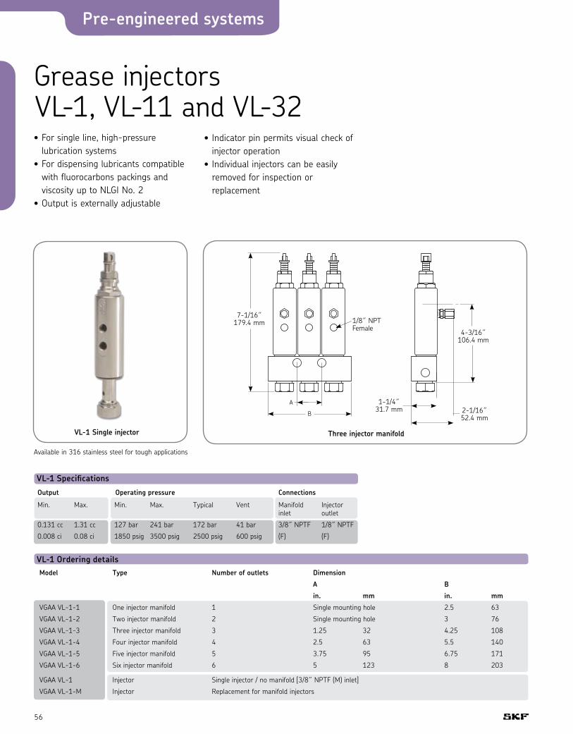
Pre-engineered systems
56
• For single line, high-pressure lubrication systems
• For dispensing lubricants compatible with fluorocarbons packings and viscosity up to NLGI No. 2
• Output is externally adjustable
Grease injectors VL-1, VL-11 and VL-32
VL-1 Specifications
Output Operating pressure Connections
Min. Max. Min. Max. Typical Vent Manifold Injector inlet outlet
0.131 cc 1.31 cc 127 bar 241 bar 172 bar 41 bar 3/8˝ NPTF 1/8˝ NPTF
0.008 ci 0.08 ci 1850 psig 3500 psig 2500 psig 600 psig (F) (F)
VL-1 Ordering detailsModel Type Number of outlets Dimension
A B
in. mm in. mm
VGAA VL-1-1 One injector manifold 1 Single mounting hole 2.5 63
VGAA VL-1-2 Two injector manifold 2 Single mounting hole 3 76
VGAA VL-1-3 Three injector manifold 3 1.25 32 4.25 108
VGAA VL-1-4 Four injector manifold 4 2.5 63 5.5 140
VGAA VL-1-5 Five injector manifold 5 3.75 95 6.75 171
VGAA VL-1-6 Six injector manifold 6 5 123 8 203
VGAA VL-1 Injector Single injector / no manifold [3/8˝ NPTF (M) inlet]
VGAA VL-1-M Injector Replacement for manifold injectors
4-3/16˝ 106.4 mm
7-1/16˝ 179.4 mm
1-1/4˝ 31.7 mm 2-1/16˝
52.4 mm
Three injector manifoldVL-1 Single injector
A
B
1/8˝ NPT Female
• Indicator pin permits visual check of injector operation
• Individual injectors can be easily removed for inspection or replacement
Available in 316 stainless steel for tough applications
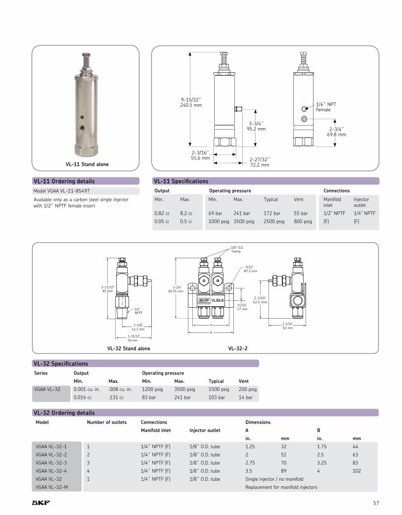
57
VL-11 SpecificationsOutput Operating pressure Connections
Min. Max. Min. Max. Typical Vent Manifold Injector inlet outlet
0.82 cc 8.2 cc 69 bar 241 bar 172 bar 55 bar 1/2” NPTF 1/4” NPTF
0.05 ci 0.5 ci 1000 psig 3500 psig 2500 psig 800 psig (F) (F)
Model VGAA VL-11-85497
VL-32 Ordering details
VL-11 Ordering details
Model Number of outlets Connections Dimensions
Manifold inlet Injector outlet A B
in. mm in. mm
VGAA VL-32-1 1 1/4˝ NPTF (F) 1/8˝ O.D. tube 1.25 32 1.75 44
VGAA VL-32-2 2 1/4˝ NPTF (F) 1/8˝ O.D. tube 2 51 2.5 63
VGAA VL-32-3 3 1/4˝ NPTF (F) 1/8˝ O.D. tube 2.75 70 3.25 83
VGAA VL-32-4 4 1/4˝ NPTF (F) 1/8˝ O.D. tube 3.5 89 4 102
VGAA VL-32 1 1/4˝ NPTF (F) 1/8˝ O.D. tube Single injector / no manifold
VGAA VL-32-M Replacement for manifold injectors
VL-32 SpecificationsSeries Output Operating pressure
Min. Max. Min. Max. Typical Vent
VGAA VL-32 0.001 cu. in. .008 cu. in. 1200 psig 3500 psig 1500 psig 200 psig
0.016 cc .131 cc 83 bar 241 bar 103 bar 14 bar
9-15/32˝ 240.5 mm 1/4˝ NPT
Female
2-3/16˝ 55.6 mm 2-27/32˝
72.2 mm
3-3/4˝ 95.2 mm 2-3/4˝
69.8 mm
VL-32 Stand alone
VL-11 Stand alone
VL-32-2
Available only as a carbon steel single injector with 1/2˝ NPTF female insert

Pre-engineered systems
58
VSP Modular progressive feedersModular and flexible for grease systems up to 4,000 PSI
Each VSP assembly includes a minimum of three distributor segments, a base plate, an inlet section, and an end section.
Twin piston sections are ported to create separate outputs for two lube points. Single sections combine the output from both ends of the piston and send it to a single lube point.
Features• Precise monitoring • Modular design for flexibility• Simple installation and operation• Individual valve adjustability• Lubricate up to 16 points
per assembly• “Drop-in” replacement for
competitive valve assemblies • SAE type fluorocarbon o-ring
sealed piston bores• 90 durometer fluorocarbon
o-rings standard on all valve and intermediate sections
• Corrosion protected steel material
VSP feeder specifications VSP dimension detailsMaximum cycle rate Maximum pressure Maximum temperature Lubricant
60 / minute with cycle pin 4000 PSI 200° F Oil or grease
200 / minute without cycle pin (or with Prox cycle switch) 4000 PSI 200° F Oil or grease
Cross-porting or singling sections can be done to increase the flow to a single point or to lubricate an odd number of points.
A bypass section can be used to provide grease to additional lubrication points or it can eliminate an entire piston section.
Number of sections L1 dimension
3 90.881 mm4 114.300 mm5 137.718 mm6 161.138 mm7 184.556 mm8 207.975 mm
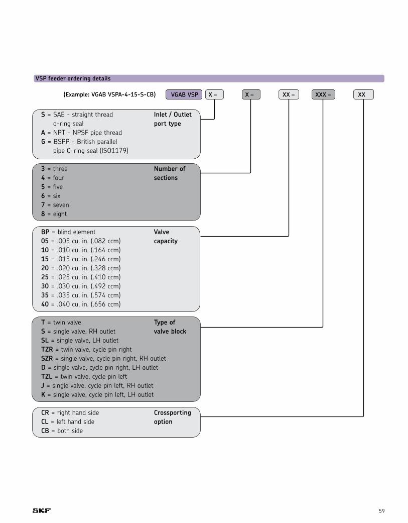
59
VGAB VSP X – X – XX – XXX – XX
S = SAE - straight thread Inlet / Outlet o-ring seal port typeA = NPT - NPSF pipe threadG = BSPP - British parallel pipe 0-ring seal (ISO1179)
3 = three Number of4 = four sections5 = five6 = six7 = seven8 = eight
BP = blind element Valve05 = .005 cu. in. (.082 ccm) capacity10 = .010 cu. in. (.164 ccm)15 = .015 cu. in. (.246 ccm)20 = .020 cu. in. (.328 ccm)25 = .025 cu. in. (.410 ccm) 30 = .030 cu. in. (.492 ccm)35 = .035 cu. in. (.574 ccm)40 = .040 cu. in. (.656 ccm)
T = twin valve Type ofS = single valve, RH outlet valve blockSL = single valve, LH outletTZR = twin valve, cycle pin rightSZR = single valve, cycle pin right, RH outletD = single valve, cycle pin right, LH outletTZL = twin valve, cycle pin leftJ = single valve, cycle pin left, RH outletK = single valve, cycle pin left, LH outlet
CR = right hand side CrossportingCL = left hand side optionCB = both side
VSP feeder ordering details
(Example: VGAB VSPA-4-15-S-CB)
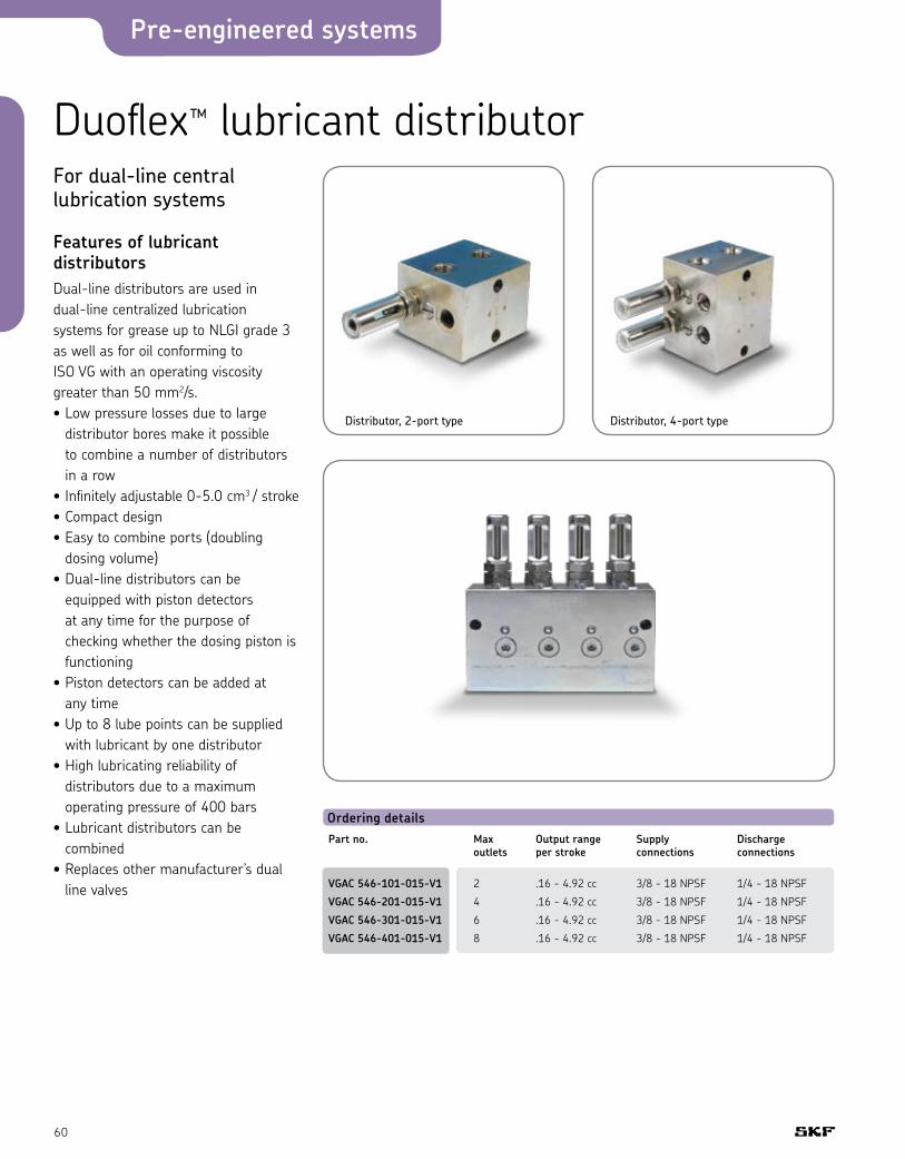
Pre-engineered systems
60
Duoflex™ lubricant distributorFor dual-line central lubrication systems
Features of lubricant distributorsDual-line distributors are used in dual-line centralized lubrication systems for grease up to NLGI grade 3 as well as for oil conforming to ISO VG with an operating viscosity greater than 50 mm2/s. • Low pressure losses due to large
distributor bores make it possible to combine a number of distributors in a row
• Infinitely adjustable 0-5.0 cm3 / stroke• Compact design• Easy to combine ports (doubling
dosing volume)• Dual-line distributors can be
equipped with piston detectors at any time for the purpose of checking whether the dosing piston is functioning
• Piston detectors can be added at any time
• Up to 8 lube points can be supplied with lubricant by one distributor
• High lubricating reliability of distributors due to a maximum operating pressure of 400 bars
• Lubricant distributors can be combined
• Replaces other manufacturer’s dual line valves
Ordering detailsPart no. Max Output range Supply Discharge outlets per stroke connections connections
VGAC 546-101-015-V1 2 .16 - 4.92 cc 3/8 - 18 NPSF 1/4 - 18 NPSF
VGAC 546-201-015-V1 4 .16 - 4.92 cc 3/8 - 18 NPSF 1/4 - 18 NPSF
VGAC 546-301-015-V1 6 .16 - 4.92 cc 3/8 - 18 NPSF 1/4 - 18 NPSF
VGAC 546-401-015-V1 8 .16 - 4.92 cc 3/8 - 18 NPSF 1/4 - 18 NPSF
Distributor, 2-port type Distributor, 4-port type
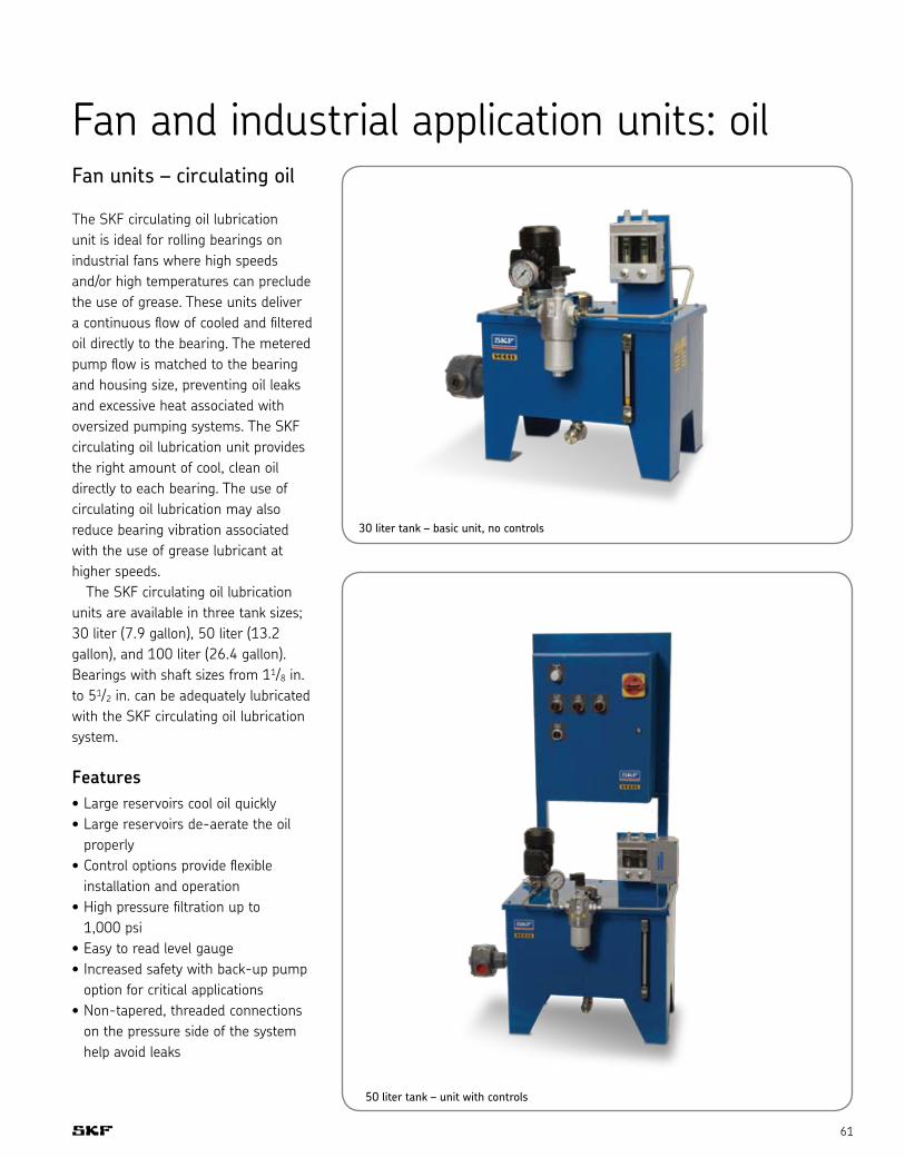
61
Fan and industrial application units: oilFan units – circulating oil
The SKF circulating oil lubrication unit is ideal for rolling bearings on industrial fans where high speeds and/or high temperatures can preclude the use of grease. These units deliver a continuous flow of cooled and filtered oil directly to the bearing. The metered pump flow is matched to the bearing and housing size, preventing oil leaks and excessive heat associated with oversized pumping systems. The SKF circulating oil lubrication unit provides the right amount of cool, clean oil directly to each bearing. The use of circulating oil lubrication may also reduce bearing vibration associated with the use of grease lubricant at higher speeds. The SKF circulating oil lubrication units are available in three tank sizes; 30 liter (7.9 gallon), 50 liter (13.2 gallon), and 100 liter (26.4 gallon). Bearings with shaft sizes from 11/8 in. to 51/2 in. can be adequately lubricated with the SKF circulating oil lubrication system.
Features• Large reservoirs cool oil quickly • Large reservoirs de-aerate the oil
properly• Control options provide flexible
installation and operation • High pressure filtration up to
1,000 psi• Easy to read level gauge• Increased safety with back-up pump
option for critical applications• Non-tapered, threaded connections
on the pressure side of the system help avoid leaks
30 liter tank – basic unit, no controls
50 liter tank – unit with controls

Pre-engineered systems
62
Product selection - important noteThe following table is only a guide to assist in selecting the appropriate SKF circulating oil lubrication unit. Please consult SKF Application Engineering before purchasing and installing this product to ensure the proper unit has been selected based on all operating and application parameters.
Ordering detailsHousing no. Shaft sizes Standard housings - drain size SKF circulating oil lubrication unit*
SAF 507 11/8, 13/16, 11/4 1/8” NPT VGRV MF2………V511
SAF 509 13/8, 17/16, 11/2 1/8” NPT VGRV MF2………V511
SAF 510 15/8, 111/16, 13/4 1/8” NPT VGRV MF2………V511
SAF 511 113/16, 17/8, 115/16, 2 1/8” NPT VGRV MF2………V511
SAF 513 2, 21/16, 21/8, 23/16, 21/4 1/8” NPT VGRV MF5………V517
SAF 515 23/8, 27/16, 21/2 1/4” NPT VGRV MF5………V517
SAF 516 29/16, 25/8, 211/16, 23/4 3/8” NPT VGRV MF5………V517
SAF 517 213/16, 27/8, 215/16, 3 3/8” NPT VGRV MF5………V517
SAF 518 31/16, 31/8, 33/16, 31/4 3/8” NPT VGRV MF10………V524
SAF 520 35/16, 33/8, 37/16, 31/2 3/8” NPT VGRV MF10………V524
SAF 522 313/16, 37/8, 315/16, 4 3/8” NPT VGRV MF10………V524
SAF 524 41/16, 41/8, 43/16, 41/4 1/2” NPT VGRV MF10………V524
SAF 526 45/16, 43/8, 47/16, 41/2 1/2” NPT VGRV MF210………V532
SAF 528 413/16, 47/8, 415/16 3/4” NPT VGRV MF210………V532
SAF 530 51/8, 53/16, 51/4 3/4” NPT VGRV MF210………V532
SAF 532 53/8, 57/16, 51/2 3/4” NPT VGRV MF210………V532
Ordering detailsHousing no. Shaft sizes VZ 708, VZ 709 housings - drain size SKF circulating oil lubrication unit*
SAF 507 11/8, 13/16, 11/4 3/8” NPT VGRV MF5………V517
SAF 509 13/8, 17/16, 11/2 3/8” NPT VGRV MF5………V517
SAF 510 15/8, 111/16, 13/4 3/8” NPT VGRV MF5………V517
SAF 511 113/16, 17/8, 15/16, 2 3/8” NPT VGRV MF5………V517
SAF 513 2, 21/16, 21/8, 23/16, 21/4 3/8” NPT VGRV MF10………V524
SAF 515 23/8, 27/16, 21/2 3/8” NPT VGRV MF10………V524
SAF 516 29/16, 25/8, 211/16, 23/4 3/4” NPT VGRV MF10………V524
SAF 517 213/16, 27/8, 215/16, 3 3/4” NPT VGRV MF10………V524
SAF 518 31/16, 31/8, 33/16, 31/4 3/4” NPT VGRV MF210………V532
SAF 520 35/16, 33/8, 37/16, 31/2 3/4” NPT VGRV MF210………V532
SAF 522 313/16, 37/8, 315/16, 4 3/4” NPT VGRV MF210………V532
SAF 524 41/16, 41/8, 43/16, 41/4 3/4” NPT VGRV MF210………V532
SAF 526 45/16, 43/8, 47/16, 41/2 3/4” NPT VGRV MF210………V532
SAF 528 413/16, 47/8, 415/16 1” NPT Consult SKF Application Engineering
SAF 530 51/8, 53/16, 51/4 1” NPT Consult SKF Application Engineering
SAF 532 53/8, 57/16, 51/2 1” NPT Consult SKF Application Engineering
* Based on oil drain rate using two drain holes.Consult SKF Application Engineering for specific recommendations.

63
Ordering detailsPart no. Description Specification
VGRV MF2-BW30-V511 Basic unit 0.24 liters / min flow rate
VGRV MF2X2-BW30-V511 Safety critical unit (back-up pump) 30 liter metal reservoir
VGRV MF2-BAW30-V511 Basic unit with controls
VGRV MF2X2-BAW30-V511 Safety critical unit with controls
VGRV MF5-BW50-V517 Basic unit 0.52 liters / min flow rate
VGRV MF5X2-BW50-V517 Safety critical unit (back-up pump) 50 liter metal reservoir
VGRV MF5-BAW50-V517 Basic unit with controls
VGRV MF5X2-BAW50-V517 Safety critical unit with controls
VGRV MF10-BW100-V524 Basic unit 1.1 liters / min flow rate
VGRV MF10X2-BW100-V524 Safety critical unit (back-up pump) 100 liter metal reservoir
VGRV MF10-BAW100-V524 Basic unit with controls
VGRV MF10X2-BAW100-V524 Safety critical unit with controls
VGRV MF210-BW100-V532 Basic unit 2.4 liters / min flow rate
VGRV MF210X2-BW100-V532 Safety critical unit (back-up pump) 100 liter metal reservoir
VGRV MF210-BAW100-V532 Basic unit with controls
VGRV MF210X2-BAW100-V532 Safety critical unit with controls
All units include• Motor, 230/460 V, 60 Hz • Single circuit gear pump unit with adjustable pressure regulating valve• Sight glass with oil level • Level switch• Return port• Pressure gauge• 10 micron filter with electrical contamination indication• Two-point flow meter• Heater with integrated thermostat - 2 kW, 460 V, 60 Hz
Available options• Oil over air heat exchanger• Water cooled heat exchanger• Stainless steel reservoir• Explosion-proof components• Stay dry desiccant tank breathers (see Accessories chapter)• 24 V DC• Temperature switches• Pressure switches• Higher capacity units

Pre-engineered systems
64
Single-circuit pumpsThe pump units specified in this section are lubricant delivery pumps without pressure relief fixtures and are designed for continuous operation in circulating and hydrostatic lubrication systems. These pump units may also be used for hydraulic tasks to the extent permitted by the pressure and viscosity ranges stated in the tables. The drive is provided by a three-phase motor designed for a rated voltage of 230/400 V to DIN IEC 38. The permissible pressure and delivery rates vary with the viscosity. When using oils with viscosities outside the indicated ranges (spindle oils and highly viscous oils), please consult SKF for further information. Please note that even standard oils may become thin-bodied or highly viscous due to changes in temperature.
Ambient temperature maximum +40° C (104° F)Lubricant temperature 0° C to +80° C (32° F to 176° F)
Gear pump unit Pump unit with reservoir
Explanation of the hydraulic functionReferring to the diagrams below, oil is sucked in at S and flows through the pressure duct in direction P. The oil pressure closes valve V and opens valve E3 against spring tension. If air is entrained (due to low oil level in the reservoir), valve V remains open and bleeds the air or the air-intermixed oil into the return duct (see arrows marking the flow in directions R1 and R2 respectively). Valve C1 allows the excess-pressure oil to flow into the return duct.
Explanation of the structural differencesWith type MF, the short screw plug D2 leaves flanged port R2 open – contrary to D1 with type M – and a plug seals external port R1. Flanged port R2 of the return duct discharges directly into the reservoir without any threaded connections (see Fig. 2 and 3).
Type MF units for flange-mounting on oil reservoir
Use a special sealed pump for horizontal flange-mounting of the unit beneath oil level
Figure 1 Figure 2 Figure 3

65
Ordering details - single circuit gear pump unitsFor flange- Maximum Permissible Suction head Three-phase motor mounting on back operating (with open Rated Rated Rated current Suctionoil reservoir Output1) pressure viscosity range pressure line) output speed at 50Hz, 230/400 V port SOrder no. [l/min] [bars] [mm2/s] [mm] [kW] [rpm] [A] thread d1
VGBA MF2 0.24 60 140 - 1000 500 0.13 3300 0.65 / 0.37 M14 x 1.5
VGBA MF5 0.6 27 20 - 1000 500 0.13 3300 0.65 / 0.37 M14 x 1.5
VGBA MF10 1.2 27 20 - 1000 500 0.13 3300 0.65 / 0.37 M14 x 1.5
VGBA MF210 2.4 27 20 - 1000 500 0.13 3300 0.65 / 0.37 M14 x 1.5
1) Output based on an operating viscosity of 140 mm2/s at a back pressure of p = 5 bars2) Also see leaflet 1-1202-US page 4: Multirange voltage motors.Single-circuit units complete with reservoir see page 61.
Standard dimensions of reservoirs starting at 30 liters (dimensions in mm)Reservoir Height Width Depth Center Center Holecapacity distance distance[liters] h h2 h3 b1 d1 b2 d2 Ø
30 375 245 237 510 320 430 240 14
50 480 310 300 570 350 490 270 14
100 510 340 326 710 500 630 420 14
30 and 50 liter reservoirs available, also without legs, for wall-mounting.
1 = Oil filler cap2 = Oil strainer3 = Float switch4 = Gear or oil strainer gerotor pump unit6 = Oil level indicator7 = Oil drain plug
Reservoir and cover: hammered enamel finish The complete reservoir units are also available in conformity with the regulations of the automobile industry. DIN and special reservoirs on request.
Example: 50 liter reservoir
Return line R screw-plugged before delivery

Pre-engineered systems
66
Safeflow™ oil flowmetersSafeflow™ oil flowmeters are used for controlling and measuring the flow rate of lubricants in paper machine oil lubrication systems. The base is made of durable aluminum. The flow tube is made of glass, so high temperatures and the use of synthetic oils should present no problems. The Safeflow flowmeter has a straight glass flow tube with an internal calibrated cone extending along its vertical axis. The float is cylindrical, its O.D. being the same dimensions as the I.D. of the flow tube, with an annular opening through its center along its vertical axis. In operation, the calibrated cone extends through the annular opening in the float, creating the variable orifice needed for measurement as the float moves with flow changes. Because the oil flows through the float, rather than around it as in ordinary flowmeters, the float is always clearly visible. A white Teflon ring on the float marks the reading point and wipes the inside wall of the glass tube. The flowmeter can be field calibrated so that when the desired oil flow is properly adjusted, the white ring will line up with a predetermined mark. This makes it easy to monitor banks of flowmeters with different required flows because all floats will be at the same level and it will not be necessary to remember the correct flow value for each bearing.
Flow change alarm systemThe oil flow through each Safeflow flowmeter can be remotely and continuously monitored. The alarm system consists of one alarm sensor for each flow tube and one monitoring unit for up to ten alarm sensors. The alarm sensor is an inductive proximity
switch, which identifies the location of a metal float in the tube. The monitoring unit contains the terminals and the power supply for ten sensors. The system transmits either a single alarm from each bank of meters or a separate signal from each flow tube. The alarm delay can also be selected to avoid false alarms.
Ordering detailsFor use with . . . Basic Basic Safety unit unit with critical controls unit
30 fan unit tank capacity (liters) SF05A-02UX SF05A-02UX SF05A-02UA-BSS
50 fan unit tank capacity (liters) SF10A-02UX SF10A-02UX SF10A-02UA-BSS
100 fan unit tank capacity (liters) SF10A-02UX SF10A-02UX SF10A-02UA-BSS
Flow rate SF05A SF10A
100cSt (460 SSU) 0.1 - 0.7 liters / min 0.1 - 3.0 liters / min
0.2 - 1.5 pints / min 0.2 - 6.3 pints / min
220cSt (1000 SSU) 0.04 - 0.35 liters / min 0.1 - 1.7 liters / min
0.08 - 0.74 pints / min 0.2 - 3.6 pints / min
Note: When ordering, use SKF prefix designation VGDC. Example: VGDC SF10A-02UA-BSS

67
Level switchesFor oil, hydraulic and fluid reservoirs
Level switches are used to monitor the level of fluids in unpressurized res-ervoirs. Various versions are available to meet the different requirements necessary for the monitoring of fluid levels.• Switches with one switching point
(VGDA WS32-…), e.g. ones used to monitor the minimum level of fluid in a reservoir.
• Switches with two switching points (VGDA WS35-…), likewise used to monitor the minimum level of fluid, emit an advance warning before a critical level is reached and without having to shut down the machine. Before the second switching point is reached, there is still enough oil in the reservoir for a shift to be completed without having to stop the machine or interrupt work.
• Switches with two switching points (VGDA WS33-…), e.g. for a minimum and maximum level of fluid in the reservoir, automatic topping up of the reservoir being terminated, for example, before the maximum level is reached.
Further level switches, e.g. for other fluids like NLGI grades 000 and 00 grease, are available on request (capacitive proximity switches).
Tips for the use of level switchesPay attention to the viscosity of oil!Only use oils and other fluids with a maximum effective viscosity of 1,500 mm²/s.
VGDA WS68
VGDA WS32-2 VGDA WS35-S30
Fluids with an effective viscosity greater than 1,500 mm²/s can lead to indication failures due to the increase in shear forces between the float and contact tube.
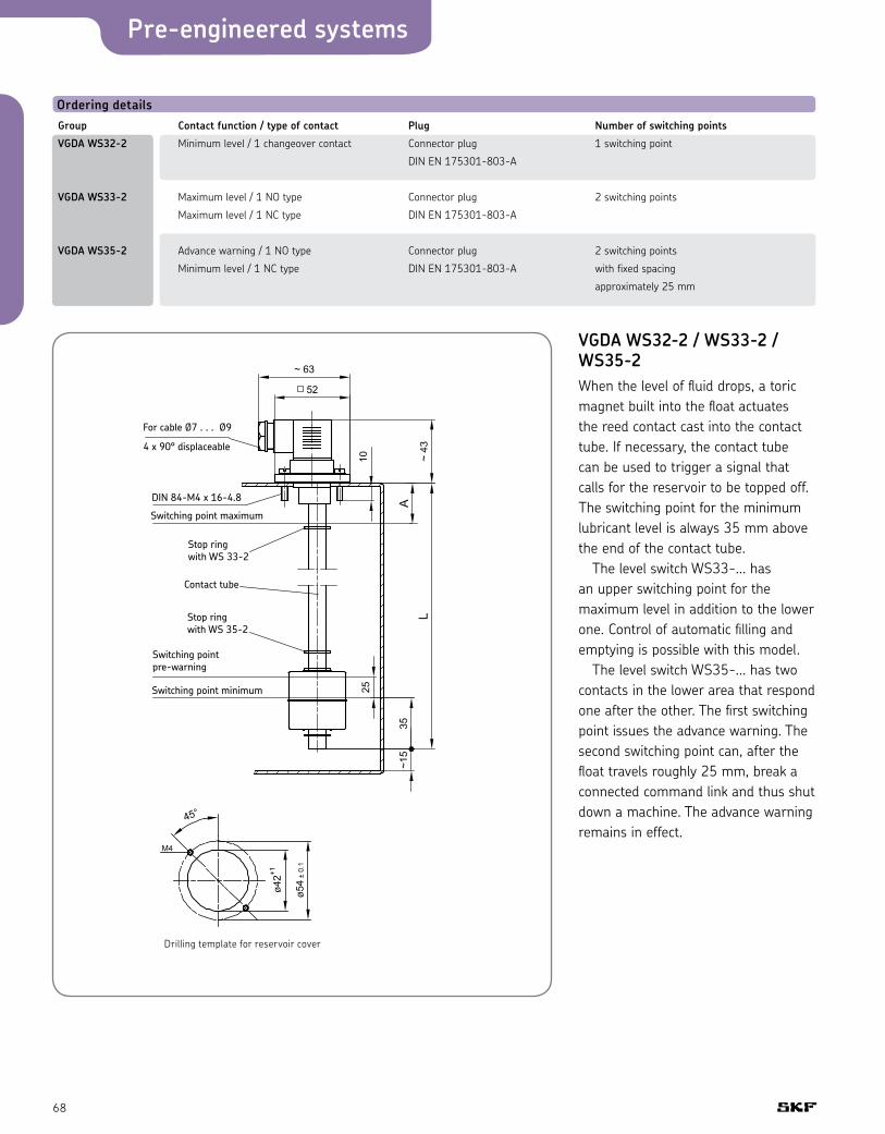
Pre-engineered systems
68
Ordering detailsGroup Contact function / type of contact Plug Number of switching points
VGDA WS32-2 Minimum level / 1 changeover contact Connector plug 1 switching point
DIN EN 175301-803-A
VGDA WS33-2 Maximum level / 1 NO type Connector plug 2 switching points
Maximum level / 1 NC type DIN EN 175301-803-A
VGDA WS35-2 Advance warning / 1 NO type Connector plug 2 switching points
Minimum level / 1 NC type DIN EN 175301-803-A with fixed spacing
approximately 25 mm
VGDA WS32-2 / WS33-2 / WS35-2When the level of fluid drops, a toric magnet built into the float actuates the reed contact cast into the contact tube. If necessary, the contact tube can be used to trigger a signal that calls for the reservoir to be topped off. The switching point for the minimum lubricant level is always 35 mm above the end of the contact tube. The level switch WS33-... has an upper switching point for the maximum level in addition to the lower one. Control of automatic filling and emptying is possible with this model. The level switch WS35-... has two contacts in the lower area that respond one after the other. The first switching point issues the advance warning. The second switching point can, after the float travels roughly 25 mm, break a connected command link and thus shut down a machine. The advance warning remains in effect.
Drilling template for reservoir cover

69
Ordering exampleWhen ordering, please also indicate the desired lengths A (minimum 50 mm at VGDA WS33...) and L (at VGDA WS32... minimum 100 mm; at VGDA WS33... and VGDA WS35... minimum 120 mm) in addition. Please observe preferred lengths.Preferred lengths A = 50, 65 and 100 mm
Ordering examples: VGDA WS32-2 with order length L = 150 mm: Order no.: VGDA WS32-2-150
VGDA WS33-2 with order length A = 50 mm, L = 200 mm:Order no.: VGDA WS33-2-50-200
Preferred lengths for order length L:100, 125, 150, 200, 230, 250, 290, 315, 350, 400, 450, 500 mm
VGDA WS32-2 for minimum level
Types of contact 1 changeover – for minimum level(magnetically actuated reed contact)
FunctionAfter the level of fluid drops to a minimum level, contact 1 – 2 opens and contact 1 – 3 closes.
VGDA WS33-2 for minimum level and maximum level
Types of contact 1 NO type – for maximum level1 NC type – for minimum level(magnetically actuated reed contacts)
FunctionContact 1 – 3 closes after the fluid rises to a maximum level;Contact 1 – 2 opens after the fluid drops to a minimum level.
VGDA WS35-2 for minimum level with pre-warning
Types of contact 1 NO type – pre-warning 1 NC type – for minimum level(magnetically actuated reed contacts)
FunctionAfter the level of fluid drops to 25 mm above the minimum filling level, contact 1 – 3 closes; if the level of fluid continues to drop to the min. level, contact 1 – 2 opens.

Pre-engineered systems
70
Lubrication systems for tabletop chain‘Dry lubrication’ systems for filling and packaging conveyors in the food industry
ApplicationsThe ‘dry lubrication’ systems eliminates the use of water-soluble lubricants. Using special lubricants, these systems have been developed to lubricate belt conveyor surfaces, as well as the conveyor guides, for the transport of products on bottling and packaging conveyors. A metered volume of lubricant is applied to the belt surface by means of coating plates that contact the conveyor chain at the same time lubricant is directly injected into the conveyor guide with the same lubrication unit. The metered volume of lubricant is independent of any possible lubricant viscosity variation, the line length or the lube point number. Considering the large diversity of conveyors, several system types have been designed in order to suit every kind of application. ‘Dry lubrication’ systems are used on filling lines for beverage cartons, plastic bottles, and so on, in the following segments of the food industry:• Milk and dairy plants• Fruit juice, sauce and soup
production• Bottled water production• Beverages (soda, beer, etc.)And in many other fields such as:• Cleaning products• Cosmetics• Pharmaceuticals
Features• Better sliding of the products• Reduced chain wear• Safety and cleanliness• Dry environment, no water• Less metal corrosion• No deterioration of the conveyed
products in the holding area • No friction noise or “stick-slip” effect• No bacterial growth• Complies with environmental
standards• Approved for use in food applications
Problems on line conveyors Due to the speed difference between the filling machine and the packaging machine, or the failure of one of them, products slow down, fall and collect on the belt conveyor at the end of the line. At the same time guides are supporting the conveyor belt where there is continuous friction.
If the friction between the belt and the product is too high (without lubrication), package bottoms can be damaged, especially cartons. The belt then needs more power for moving, resulting in belt damage. A lubrication system helps to keep a constant and sufficient friction coefficient. It can be adapted to any production line (conveyor belt type, carried products).- Too much friction (insufficient sliding)
results in: • Possible deterioration of the
products (especially cartons) • More power consumption for the
belt motion (engine over-current extreme tension of the belt)
• Possible falling of the products when changing direction
• More wear on the belt surface and guides
- Where there is not enough friction, products slide too much and it is hard to carry them properly (they slow down or stop moving completely)
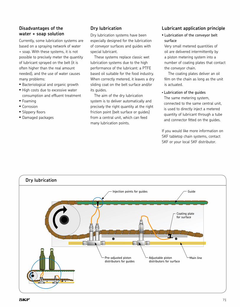
71
Disadvantages of the water + soap solutionCurrently, some lubrication systems are based on a spraying network of water + soap. With these systems, it is not possible to precisely meter the quantity of lubricant sprayed on the belt (it is often higher than the real amount needed), and the use of water causes many problems:• Bacteriological and organic growth• High costs due to excessive water
consumption and effluent treatment• Foaming• Corrosion• Slippery floors• Damaged packages
Dry lubricationDry lubrication systems have been especially designed for the lubrication of conveyor surfaces and guides with special lubricant. These systems replace classic wet lubrication systems due to the high performance of the lubricant: a PTFE based oil suitable for the food industry.When correctly metered, it leaves a dry sliding coat on the belt surface and/or its guides. The aim of the dry lubrication system is to deliver automatically and precisely the right quantity at the right friction point (belt surface or guides) from a central unit, which can feed many lubrication points.
Dry lubrication
Lubricant application principle• Lubrication of the conveyor belt
surface Very small metered quantities of oil are delivered intermittently by a piston metering system into a number of coating plates that contact the conveyor chain. The coating plates deliver an oil film on the chain as long as the unit is actuated.
• Lubrication of the guides The same metering system, connected to the same central unit, is used to directly inject a metered quantity of lubricant through a tube and connector fitted on the guides.
If you would like more information on SKF tabletop chain systems, contact SKF or your local SKF distributor.
Injection points for guides
Pre-adjusted piston distributors for guides
Adjustable piston distributors for surface
Main line
Guide
Coating plate for surface

Pre-engineered systems
72
Compact units for oilGroup MKU – 0.1, 0.2 or 0.5 l / min
These MKU compact units were developed to supply intermittently operated single-line central lubrication systems with lubricant. The basic model contains a gear pump with drive motor as well as the set of valves required for pressure relief and limitation (safety valve). The lubricant reservoir material is metal or plastic. The units are controlled depending on their design: • by hand
(unit with a pushbutton DK)• by an external control system• by a built-in electronic control and
monitoring unit, timer or counter with adjustable interval and monitoring time
• by a built-in electronic control unit with adjustable interval time and fixed pump running time.
The control and monitoring unit is either a timer for time-dependent control or a counter for load-dependent control.
Design features• Preliminary lubrication
(lubrication after the supply voltage is turned on)
• Pump delay time• Pressure dependent cut-off• Monitoring of pressure build-up• Monitoring of pump running time
Possible monitoring elements• Pressure switch (DS) monitors the
automatic pressure build-up• Level indicator (WS)• Pressure gauge (MA) displays the
pressure response in the main line• Monitoring contact turns off machine
if pressure fails to build up• Indicator light, green shows that
pump is running• Indicator light, red indicates a fault
if pressure fails to build up or if there is a low level of lubricant in the reservoir (only with built-in level indicator)
Ordering detailsOrder no. Delivery Reservoir Reservoir Components rate capacity material [l/min] [l] * DK DS WS MA
VGBB MKU2-KW3-22003 0.2 3 K • • • •
VGBB MKU2-KW3-22013 0.2 3 K • • • •
VGBB MKU2-KW6-22003 0.2 6 K • • • •
VGBB MKU5-KW6-22003 0.5 6 K • • • •
VGBB MKU2-BW3-22003 0.2 3 B • • • •
VGBB MKU2-BW3-22013 0.2 3 B • • • •
* Reservoir material: K = plastic B = metal• = components contained in the unit DK = Pushbutton / DS = pressure switch / WS = level indicator / MA = pressure gauge
MKU2-KW3-22003
MKU2-KW6-22003
MKU2-BW3-22003

73
Piston distributors
For single-line total-loss lubrication systems
Piston distributors meter out and distribute the oil delivered by an intermittently actuated pump. The quantities of oil for the individual lube points are determined by exchangeable metering nipples. The metered amount is indicated on the individual nipples. The amount needed
Group 350 (0.1 - 0.6 cm3) Group 390 (0.2 - 1.5 cm3)Group 340 (0.1 - 0.6 cm3)
to cover the total oil demand can then be further regulated via the lubricating frequency. To meet the required quantities and comply with spatial constraints, it is possible to choose among four distributor groups that differ in terms of their metering ranges and sizes.The functional principle of the groups is the same but there are differences in design.
Different distributor groups can be used in one installation. Please note: Seal material: NBR. In general, the operating conditions specified for the respective pump units will also apply to the distributors.
Limit values for the distributors: Temperature range: 0° C to + 80° C (32° F to 176° F) Effective oil viscosity: 5 to 2,500 mm²/s
Function
1. The amount of oil intended for the lube
point is stored in front of the piston in
the distributor.
2. When the central lubrication pump
starts delivering oil, the piston moves
and the oil in front of it is fed to the
lube point at a main line pressure of
12-45 bars.
3. After the pressure is relieved (≤ 1 bar)
in the main line, the distributor‘s piston
returns to its initial position and once
again lets a certain quantity of oil flow
into the space in front of it.
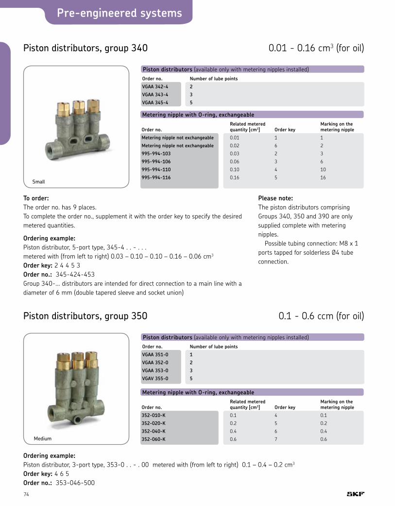
Pre-engineered systems
74
Piston distributors, group 340
Piston distributors (available only with metering nipples installed)Order no. Number of lube points
VGAA 342-4 2
VGAA 343-4 3
VGAA 345-4 5
Metering nipple with O-ring, exchangeable Related metered Marking on theOrder no. quantity [cm3] Order key metering nipple
Metering nipple not exchangeable 0.01 1 1
Metering nipple not exchangeable 0.02 6 2
995-994-103 0.03 2 3
995-994-106 0.06 3 6
995-994-110 0.10 4 10
995-994-116 0.16 5 16
0.01 - 0.16 cm3 (for oil)
Small
To order:The order no. has 9 places. To complete the order no., supplement it with the order key to specify the desired metered quantities.
Ordering example:Piston distributor, 5-port type, 345-4 . . - . . . metered with (from left to right) 0.03 – 0.10 – 0.10 – 0.16 – 0.06 cm3 Order key: 2 4 4 5 3 Order no.: 345-424-453 Group 340-... distributors are intended for direct connection to a main line with a diamete r of 6 mm (double tapered sleeve and socket union)
Piston distributors, group 350
Piston distributors (available only with metering nipples installed)Order no. Number of lube points
VGAA 351-0 1
VGAA 352-0 2
VGAA 353-0 3
VGAV 355-0 5
Metering nipple with O-ring, exchangeable Related metered Marking on theOrder no. quantity [cm3] Order key metering nipple
352-010-K 0.1 4 0.1
352-020-K 0.2 5 0.2
352-040-K 0.4 6 0.4
352-060-K 0.6 7 0.6
0.1 - 0.6 ccm (for oil)
Medium
Ordering example:Piston distributor, 3-port type, 353-0 . . - . 00 metered with (from left to right) 0.1 – 0.4 – 0.2 cm3 Order key: 4 6 5 Order no.: 353-046-500
Please note:The piston distributors comprising Groups 340, 350 and 390 are only supplied complete with metering nipples. Possible tubing connection: M8 x 1 ports tapped for solderless Ø4 tube connection.

75
Piston distributors, group 390
Piston distributors (available only with metering nipples installed)Order no. Number of lube points
VGAA 391-0 1
VGAA 392-0 2
VGAA 393-0 3
Metering nipple with O-ring, exchangeable Related metered Marking on theOrder no. quantity [cm3] Order key metering nipple
391-020-K 0.2 5 0.2
391-040-K 0.4 6 0.4
391-060-K 0.6 7 0.6
391-100-K 1.0 8 1.0
391-150-K 1.5 9 1.5
0.2 - 1.5 cm3 (for oil)
Large
Order example:Piston distributor, 3-port type, 393-0 . . - . 00 metered with (from left to right) 1.5 – 1.0 – 0.4 cm3 Order key: 9 8 6 Order no.: 393-098-600
WasherAdapter or banjo fitting
Example of group 350 distributors:
Secondary line connections for plastic tubing:Socket union Tapered ring Reinforcing sleeve
Secondary line connections for steel tubing:Socket union
Double tapered sleeve
Metering nipple
Screw plugor adapter when main line is continued
or threaded socket when connected to a further piston distributor
Main line connections for steel tubing:Socket unionDouble tapered sleeve
for plastic tubing:Socket union Tapered sleeve Reinforcing socket
Attention! Only in the case of the piston distributors shown here is it permissible to close unneeded ports.
Ports on progressive feeders must not be closed! Feeders would block!
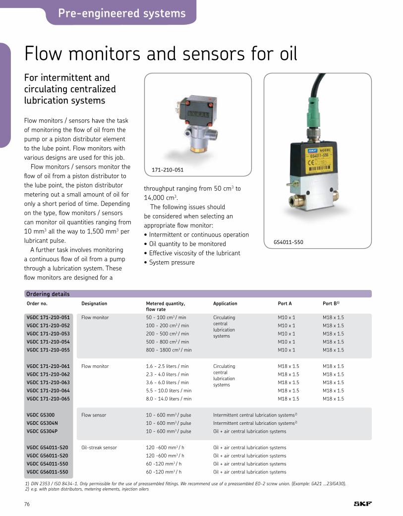
Pre-engineered systems
76
Flow monitors and sensors for oilFor intermittent and circulating centralized lubrication systems
Flow monitors / sensors have the task of monitoring the flow of oil from the pump or a piston distributor element to the lube point. Flow monitors with various designs are used for this job. Flow monitors / sensors monitor the flow of oil from a piston distributor to the lube point, the piston distributor metering out a small amount of oil for only a short period of time. Depending on the type, flow monitors / sensors can monitor oil quantities ranging from 10 mm3 all the way to 1,500 mm3 per lubricant pulse. A further task involves monitoring a continuous flow of oil from a pump through a lubrication system. These flow monitors are designed for a
171-210-051
GS4011-S50
throughput ranging from 50 cm3 to 14,000 cm3. The following issues should be considered when selecting an appropriate flow monitor:• Intermittent or continuous operation• Oil quantity to be monitored• Effective viscosity of the lubricant• System pressure
Ordering details Order no. Designation Metered quantity, Application Port A Port B1)
flow rate
VGDC 171-210-051 Flow monitor 50 - 100 cm3 / min Circulating M10 x 1 M18 x 1.5
VGDC 171-210-052 100 - 200 cm3 / min central M10 x 1 M18 x 1.5
VGDC 171-210-053 200 - 500 cm3 / min lubrication
M10 x 1 M18 x 1.5
VGDC 171-210-054 500 - 800 cm3 / min systems
M10 x 1 M18 x 1.5
VGDC 171-210-055 800 - 1800 cm3 / min M10 x 1 M18 x 1.5
VGDC 171-210-061 Flow monitor 1.6 - 2.5 liters / min Circulating M18 x 1.5 M18 x 1.5
VGDC 171-210-062 2.3 - 4.0 liters / min central M18 x 1.5 M18 x 1.5
VGDC 171-210-063 3.6 - 6.0 liters / min lubrication
M18 x 1.5 M18 x 1.5
VGDC 171-210-064 5.5 - 10.0 liters / min systems
M18 x 1.5 M18 x 1.5
VGDC 171-210-065 8.0 - 14.0 liters / min M18 x 1.5 M18 x 1.5
VGDC GS300 Flow sensor 10 - 600 mm3 / pulse Intermittent central lubrication systems2)
VGDC GS304N 10 - 600 mm3 / pulse Intermittent central lubrication systems2)
VGDC GS304P 10 - 600 mm3 / pulse Oil + air central lubrication systems
VGDC GS4011-S20 Oil-streak sensor 120 -600 mm3 / h Oil + air central lubrication systems
VGDC GS6011-S20 120 -600 mm3 / h Oil + air central lubrication systems
VGDC GS4011-S50 60 -120 mm3 / h Oil + air central lubrication systems
VGDC GS6011-S50 60 -120 mm3 / h Oil + air central lubrication systems
1) DIN 2353 / ISO 8434-1. Only permissible for the use of preassembled fittings. We recommend use of a preassembled EO-2 screw union. (Example: GA21 ...23/GA30).2) e.g. with piston distributors, metering elements, injection oilers
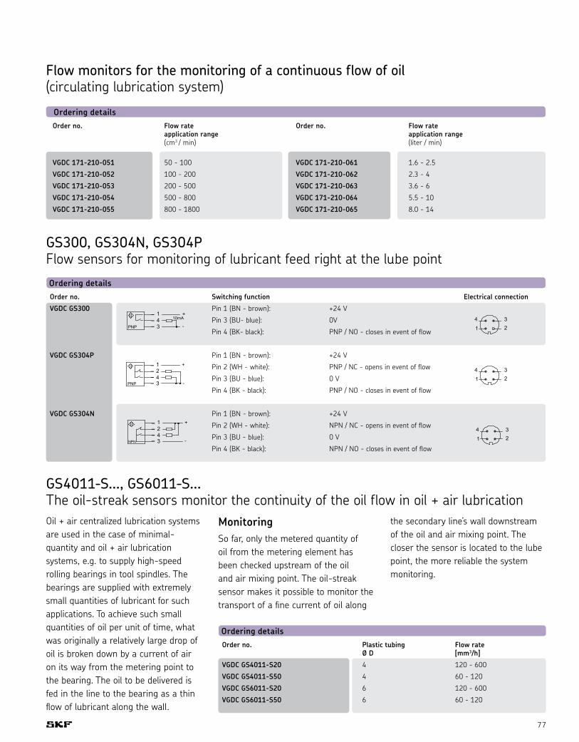
77
Flow monitors for the monitoring of a continuous flow of oil (circulating lubrication system)
Ordering detailsOrder no. Flow rate Order no. Flow rate application range application range (cm3 / min) (liter / min)
VGDC 171-210-051 50 - 100 VGDC 171-210-061 1.6 - 2.5
VGDC 171-210-052 100 - 200 VGDC 171-210-062 2.3 - 4
VGDC 171-210-053 200 - 500 VGDC 171-210-063 3.6 - 6
VGDC 171-210-054 500 - 800 VGDC 171-210-064 5.5 - 10
VGDC 171-210-055 800 - 1800 VGDC 171-210-065 8.0 - 14
GS300, GS304N, GS304P Flow sensors for monitoring of lubricant feed right at the lube pointOrdering details Order no. Switching function Electrical connection
VGDC GS300 Pin 1 (BN - brown): +24 V
Pin 3 (BU- blue): 0V
Pin 4 (BK- black): PNP / NO - closes in event of flow
VGDC GS304P Pin 1 (BN - brown): +24 V
Pin 2 (WH - white): PNP / NC - opens in event of flow
Pin 3 (BU - blue): 0 V
Pin 4 (BK - black): PNP / NO - closes in event of flow
VGDC GS304N Pin 1 (BN - brown): +24 V
Pin 2 (WH - white): NPN / NC - opens in event of flow
Pin 3 (BU - blue): 0 V
Pin 4 (BK - black): NPN / NO - closes in event of flow
GS4011-S..., GS6011-S... The oil-streak sensors monitor the continuity of the oil flow in oil + air lubricationOil + air centralized lubrication systems are used in the case of minimal-quantity and oil + air lubrication systems, e.g. to supply high-speed rolling bearings in tool spindles. The bearings are supplied with extremely small quantities of lubricant for such applications. To achieve such small quantities of oil per unit of time, what was originally a relatively large drop of oil is broken down by a current of air on its way from the metering point to the bearing. The oil to be delivered is fed in the line to the bearing as a thin flow of lubricant along the wall.
MonitoringSo far, only the metered quantity of oil from the metering element has been checked upstream of the oil and air mixing point. The oil-streak sensor makes it possible to monitor the transport of a fine current of oil along
the secondary line’s wall downstream of the oil and air mixing point. The closer the sensor is located to the lube point, the more reliable the system monitoring.
Ordering detailsOrder no. Plastic tubing Flow rate Ø D [mm3/h]
VGDC GS4011-S20 4 120 - 600
VGDC GS4011-S50 4 60 - 120
VGDC GS6011-S20 6 120 - 600
VGDC GS6011-S50 6 60 - 120
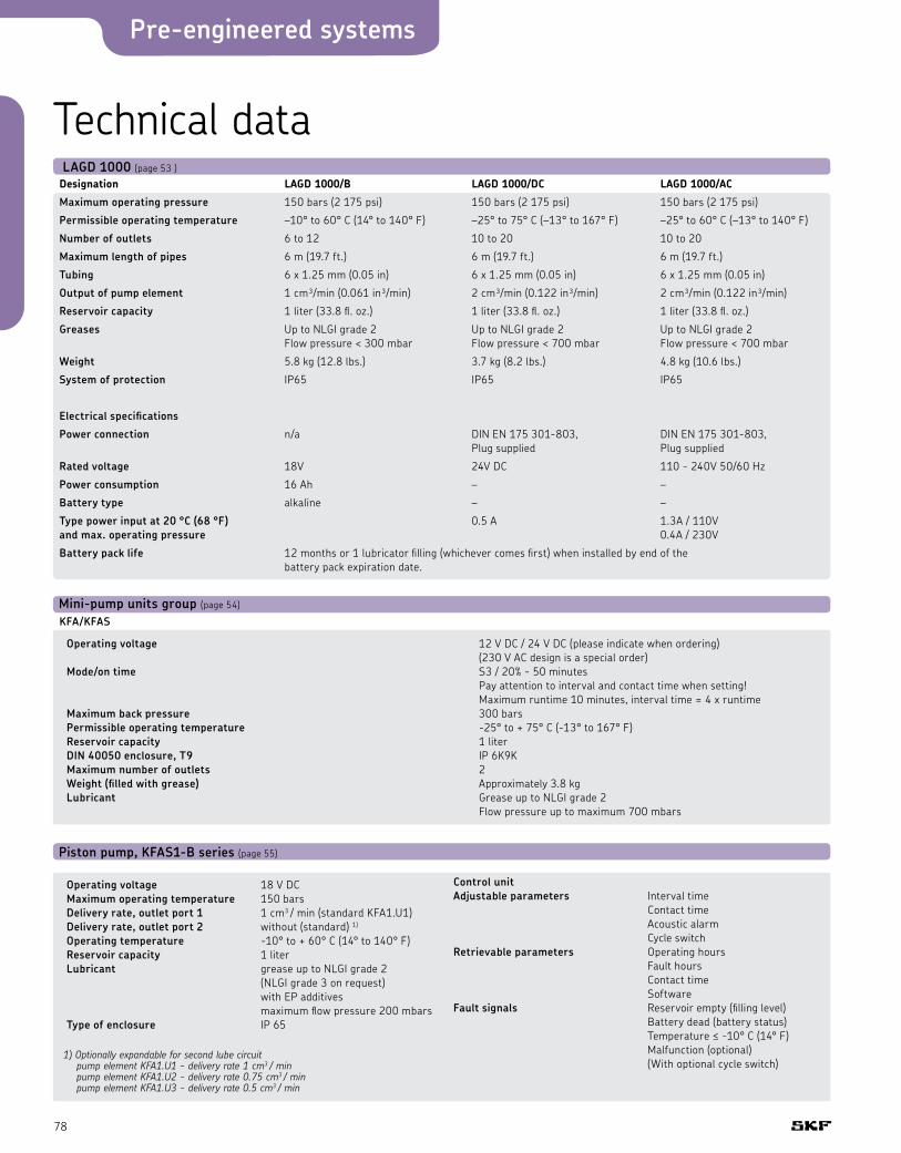
Pre-engineered systems
78
Technical data
Piston pump, KFAS1-B series (page 55)
Operating voltage 18 V DC Maximum operating temperature 150 bars Delivery rate, outlet port 1 1 cm3 / min (standard KFA1.U1) Delivery rate, outlet port 2 without (standard) 1) Operating temperature -10° to + 60° C (14° to 140° F) Reservoir capacity 1 liter Lubricant grease up to NLGI grade 2 (NLGI grade 3 on request) with EP additives maximum flow pressure 200 mbars Type of enclosure IP 65
Control unit Adjustable parameters Interval time Contact time Acoustic alarm Cycle switch Retrievable parameters Operating hours Fault hours Contact time Software Fault signals Reservoir empty (filling level) Battery dead (battery status) Temperature ≤ -10° C (14° F) Malfunction (optional) (With optional cycle switch)
1) Optionally expandable for second lube circuit pump element KFA1.U1 - delivery rate 1 cm3 / min pump element KFA1.U2 - delivery rate 0.75 cm3 / min pump element KFA1.U3 - delivery rate 0.5 cm3 / min
Mini-pump units group (page 54)
Operating voltage 12 V DC / 24 V DC (please indicate when ordering) (230 V AC design is a special order) Mode/on time S3 / 20% - 50 minutes Pay attention to interval and contact time when setting! Maximum runtime 10 minutes, interval time = 4 x runtime Maximum back pressure 300 bars Permissible operating temperature -25° to + 75° C (-13° to 167° F) Reservoir capacity 1 liter DIN 40050 enclosure, T9 IP 6K9K Maximum number of outlets 2 Weight (filled with grease) Approximately 3.8 kg Lubricant Grease up to NLGI grade 2 Flow pressure up to maximum 700 mbars
KFA/KFAS
Designation LAGD1000/B LAGD1000/DC LAGD1000/AC
Maximum operating pressure 150 bars (2 175 psi) 150 bars (2 175 psi) 150 bars (2 175 psi)
Permissible operating temperature –10° to 60° C (14° to 140° F) –25° to 75° C (–13° to 167° F) –25° to 60° C (–13° to 140° F)
Number of outlets 6 to 12 10 to 20 10 to 20
Maximum length of pipes 6 m (19.7 ft.) 6 m (19.7 ft.) 6 m (19.7 ft.)
Tubing 6 x 1.25 mm (0.05 in) 6 x 1.25 mm (0.05 in) 6 x 1.25 mm (0.05 in)
Output of pump element 1 cm³/min (0.061 in³/min) 2 cm³/min (0.122 in³/min) 2 cm³/min (0.122 in³/min)
Reservoir capacity 1 liter (33.8 fl. oz.) 1 liter (33.8 fl. oz.) 1 liter (33.8 fl. oz.)
Greases Up to NLGI grade 2 Up to NLGI grade 2 Up to NLGI grade 2 Flow pressure < 300 mbar Flow pressure < 700 mbar Flow pressure < 700 mbar
Weight 5.8 kg (12.8 lbs.) 3.7 kg (8.2 lbs.) 4.8 kg (10.6 lbs.)
System of protection IP65 IP65 IP65
Electrical specifications
Power connection n/a DIN EN 175 301-803, DIN EN 175 301-803, Plug supplied Plug supplied
Rated voltage 18V 24V DC 110 - 240V 50/60 Hz
Power consumption 16 Ah – –
Battery type alkaline – –
Type power input at 20 °C (68 °F) 0.5 A 1.3A / 110V and max. operating pressure 0.4A / 230V
Battery pack life 12 months or 1 lubricator filling (whichever comes first) when installed by end of the battery pack expiration date.
LAGD 1000 (page 53 )
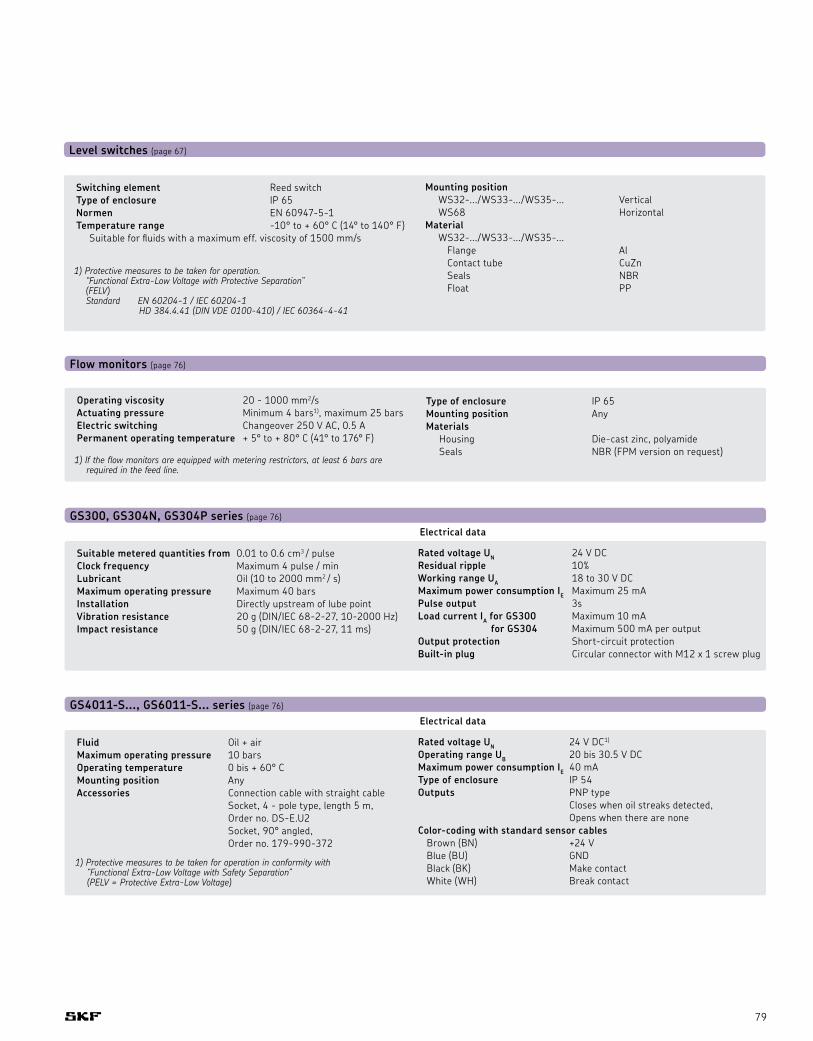
79
Flow monitors (page 76)
Operating viscosity 20 - 1000 mm2/s Actuating pressure Minimum 4 bars1), maximum 25 bars Electric switching Changeover 250 V AC, 0.5 A Permanent operating temperature + 5° to + 80° C (41° to 176° F)
Type of enclosure IP 65 Mounting position Any Materials Housing Die-cast zinc, polyamide Seals NBR (FPM version on request)
1) If the flow monitors are equipped with metering restrictors, at least 6 bars are required in the feed line.
GS300, GS304N, GS304P series (page 76)
Suitable metered quantities from 0.01 to 0.6 cm3 / pulse Clock frequency Maximum 4 pulse / min Lubricant Oil (10 to 2000 mm2 / s) Maximum operating pressure Maximum 40 bars Installation Directly upstream of lube point Vibration resistance 20 g (DIN/IEC 68-2-27, 10-2000 Hz) Impact resistance 50 g (DIN/IEC 68-2-27, 11 ms)
Electrical data
Rated voltage UN 24 V DC Residual ripple 10% Working range UA 18 to 30 V DC Maximum power consumption IE Maximum 25 mA Pulse output 3s Load current IA for GS300 Maximum 10 mA for GS304 Maximum 500 mA per output Output protection Short-circuit protection Built-in plug Circular connector with M12 x 1 screw plug
GS4011-S..., GS6011-S... series (page 76)
Fluid Oil + air Maximum operating pressure 10 bars Operating temperature 0 bis + 60° C Mounting position Any Accessories Connection cable with straight cable Socket, 4 - pole type, length 5 m, Order no. DS-E.U2 Socket, 90° angled, Order no. 179-990-372
Electrical data
Rated voltage UN 24 V DC1) Operating range UB 20 bis 30.5 V DC Maximum power consumption IE 40 mA Type of enclosure IP 54 Outputs PNP type Closes when oil streaks detected, Opens when there are none Color-coding with standard sensor cables Brown (BN) +24 V Blue (BU) GND Black (BK) Make contact White (WH) Break contact
1) Protective measures to be taken for operation in conformity with “Functional Extra-Low Voltage with Safety Separation” (PELV = Protective Extra-Low Voltage)
Level switches (page 67)
Switching element Reed switch Type of enclosure IP 65 Normen EN 60947-5-1 Temperature range -10° to + 60° C (14° to 140° F) Suitable for fluids with a maximum eff. viscosity of 1500 mm/s
Mounting position WS32-.../WS33-.../WS35-... Vertical WS68 Horizontal Material WS32-.../WS33-.../WS35-... Flange Al Contact tube CuZn Seals NBR Float PP
1) Protective measures to be taken for operation. “Functional Extra-Low Voltage with Protective Separation” (FELV) Standard EN 60204-1 / IEC 60204-1 HD 384.4.41 (DIN VDE 0100-410) / IEC 60364-4-41

Pre-engineered systems
80

81
Accessories
Disposable gloves TMBA G11D 82
Grease pumps 82
Multi-outlets drum pump GSE 84
PTEX extruder pumps 86
Lubrication accessory sets 88
Connection systems 89
Fittings and accessories 92
Electric plug-and-socket connectors 94
Stay-dry tank breathers 96
OilCheck monitor TMEH 1 98
Handheld viscometer TMVM 1 98
Portable filter cart 99
Oil Safe® 100
Technical data 102
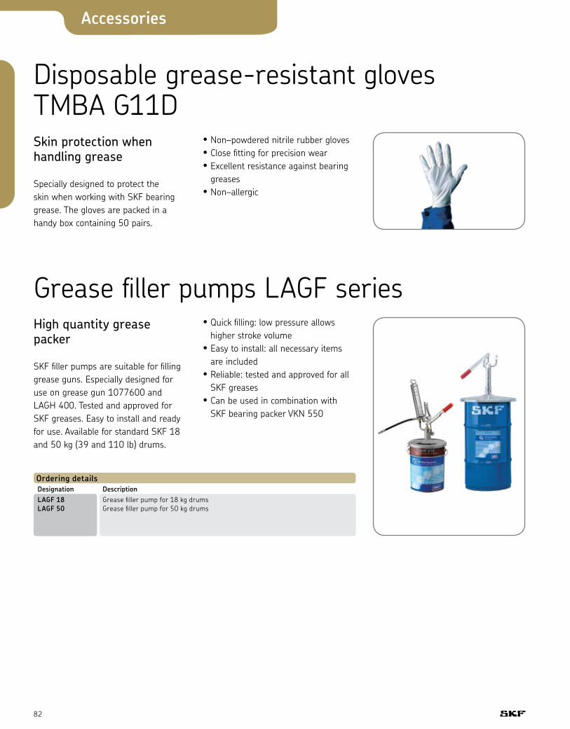
82
Accessories
Disposable grease-resistant gloves TMBA G11DSkin protection when handling grease
Specially designed to protect the skin when working with SKF bearing grease. The gloves are packed in a handy box containing 50 pairs.
• Non–powdered nitrile rubber gloves• Close fitting for precision wear• Excellent resistance against bearing
greases• Non–allergic
Grease filler pumps LAGF seriesHigh quantity grease packer
SKF filler pumps are suitable for filling grease guns. Especially designed for use on grease gun 1077600 and LAGH 400. Tested and approved for SKF greases. Easy to install and ready for use. Available for standard SKF 18 and 50 kg (39 and 110 lb) drums.
Ordering detailsDesignation DescriptionLAGF 18 Grease filler pump for 18 kg drums LAGF 50 Grease filler pump for 50 kg drums
• Quick filling: low pressure allows higher stroke volume
• Easy to install: all necessary items are included
• Reliable: tested and approved for all SKF greases
• Can be used in combination with SKF bearing packer VKN 550
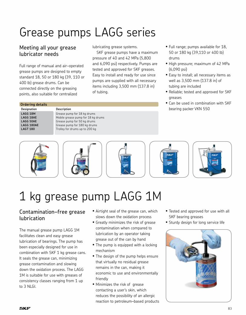
83
Grease pumps LAGG seriesMeeting all your grease lubricator needs
Full range of manual and air–operated grease pumps are designed to empty standard 18, 50 or 180 kg (39, 110 or 400 lb) grease drums. Can be connected directly on the greasing points, also suitable for centralized
lubricating grease systems. SKF grease pumps have a maximum pressure of 40 and 42 MPa (5,800 and 6,090 psi) respectively. Pumps are tested and approved for SKF greases. Easy to install and ready for use since pumps are supplied with all necessary items including 3,500 mm (137.8 in) of tubing.
• Full range; pumps available for 18, 50 or 180 kg (39,110 or 400 lb) drums
• High pressure; maximum of 42 MPa (6,090 psi)
• Easy to install; all necessary items as well as 3,500 mm (137.8 in) of tubing are included
• Reliable; tested and approved for SKF greases
• Can be used in combination with SKF bearing packer VKN 550
Ordering detailsDesignation DescriptionLAGG 18M Grease pump for 18 kg drums LAGG 18AE Mobile grease pump for 18 kg drums LAGG 50AE Grease pump for 50 kg drums LAGG 180AE Grease pump for 180 kg drums LAGT 180 Trolley for drums up to 200 kg
1 kg grease pump LAGG 1MContamination–free grease lubrication
The manual grease pump LAGG 1M facilitates clean and easy grease lubrication of bearings. The pump has been especially designed for use in combination with SKF 1 kg grease cans. It seals the grease can, minimizing grease contamination and slowing down the oxidation process. The LAGG 1M is suitable for use with greases of consistency classes ranging from 1 up to 3 NLGI.
• Airtight seal of the grease can, which slows down the oxidation process
• Greatly minimizes the risk of grease contamination when compared to lubrication by an operator taking grease out of the can by hand
• The pump is equipped with a locking mechanism
• The design of the pump helps ensure that virtually no residual grease remains in the can, making it economic to use and environmentally friendly
• Minimizes the risk of grease contacting a user’s skin, which reduces the possibility of an allergic reaction to petroleum–based products
• Tested and approved for use with all SKF bearing greases
• Sturdy design for long service life

84
Accessories
Multi-outlet drum pump GSEMulti-outlet drum pump unit, oil or grease, for centralized single-line lubrication systems
ApplicationsMulti-outlet drum pump units deliver lubricants, oil or grease, to total-loss lubrication systems. They can have up to six delivery outlets and are suited perfectly for industrial machines with several lubrication lines. They make it possible to plan simple and compact centralized lubrication systems with no need to maintain multiple lubricant containers. They work in harsh operating conditions or in severe environments. The GSE drum pump units come without a pump element. These pump elements, type GS100... have to be ordered separately, making it possible to have a great number of outlet combinations.
Features• Up to 6 pump elements• Delivers lubricant directly to several
lubrication points or to large-size progressive systems
• Adaptable motor-driven pump unit that can be mounted on drums or kegs
• A minimal level control can be added to monitor the drum lubricant level
• Working pressure up to 250 bars• The pump unit can be automated by
means of an electronic control unit
Ordering details (drum pump)Drum pump order no.* Drum Level control Follower plate
VGBE GSE0-50-11 120 lbs yes yes
VGBE GSE0-200-11 400 lbs yes yes
Ordering details (accessories)Pump element order no. - up to 6 (to be ordered separately)
VGAV GS100.6.6 piston Ø6, tube connection Ø6
VGAV GS100.6.8 piston Ø6, tube connection Ø8
VGAV GS100.8.6 piston Ø8, tube connection Ø6
VGAV GS100.8.8 piston Ø8, tube connection Ø8
Ordering details (accessories for drum)Cover order no. Follower plate order no. Drum
VGAV PT-130-50 VGAV GS1008-50 120 lbs
VGAV PT-120-200 VGAV GS1008-200 400 lbs
The drum pump units are initially delivered without pump elements. The pump elements have to be ordered separately.*) When ordering, the Order no. has to be completed with the voltage key:
+140: 460 V AC; +429: 115 V AC; +924: 24 V DC
Ordering exampleMultiline drum pump GSE for 50 kg drum, with level control and follower plate; power supply 230 V AC, 50 / 60 Hz; and three pump elements, piston Ø8 and tube connection Ø8.Order no.: VGBE GSE0-50-11+428 and VGAV GS100.8.8 (x3)See technical data on page 102.
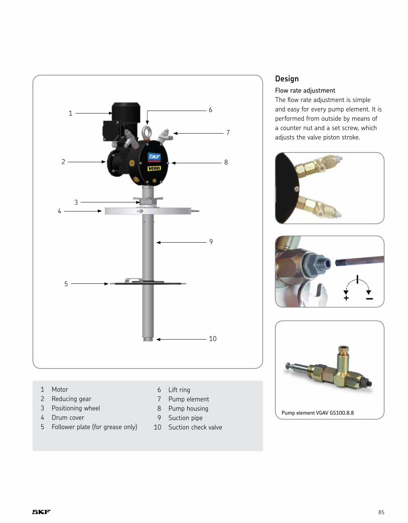
85
DesignFlow rate adjustmentThe flow rate adjustment is simple and easy for every pump element. It is performed from outside by means of a counter nut and a set screw, which adjusts the valve piston stroke.
1
2
34
5
6
7
8
9
10
1 Motor 2 Reducing gear 3 Positioning wheel 4 Drum cover 5 Follower plate (for grease only)
Pump element VGAV GS100.8.8
6 Lift ring 7 Pump element 8 Pump housing 9 Suction pipe 10 Suction check valve

86
Accessories
PTEX extruder pumpsPneumatic extruder pump for drums of grease up to NLGI grade 2Transfers lubricant to the lubrication system
The PTEX extruder pumps are pneumatically actuated pumps designed to deliver lubricant under pressure to lubrication installations. The extruder pumps transfer the lubricant - grease from NLGI grade 000 to 2 - directly from drums of large capacity (50 kg to 200 kg). The pump then delivers the grease under pressure (up to 400 bars) according to the type of the pneumatic pump to automatic lubrication installations (progressive centralized lubrication, dual-line lubrication, chain lubrication, etc.).
ApplicationsThe PTEX extruder pump is very reliable and simple to use. It uses one energy source (air) and can deliver greases up to NLGI grade 2 from different size containers. The PTEX extruder pump can be used in many industrial applications:• Automotive• Metals• Food processing• Mining and aggregate• Cement works• Assembly lines
1) Voltage keys: +924: 24 V DC +428: 230 V AC 50 / 60 Hz +429: 115 V AC 50 / 60 Hz2) The electric equipment includes the general air solenoid valve and the lubricant pressure switch
The follower plateThe follower plate is delivered with the extruder pump. But it is manufactured according to the technical data of the pump in order to ensure the extruder pump reliability and optimal tightness. Therefore you have to indicate when ordering, the inner diameter (in mm) of the lubricant drum you intend to use. At the same time, you have to select the material of the wiper seal, which corresponds the best to your lubricant. We are currently offering a FPM or a nitrile wiper seal. For any further technical information, please contact SKF.
Ordering example:PTEX-50-E-B+924, inner diameter of the drum, nitrile wiper sealExtruder pump for a 50 kg drum (inner diameter in mm), electric option (operating voltage 24 V DC), and a wiper seal in nitrile.
Features• Full consumption of the lubricant
contained in the drum (less than 0.5% of lubricant remains)
• Extruder pump range for drums with different capacities (50 and 200 kg)
• Transfer of fluid greases, NLGI grades 000 to 2
• Tailor-made follower plate perfectly meets the inner diameter of the drum
• The follower plate keeps the drum tight, preventing contamination of the lubricant
• Very easy to use• Control console with protection in
order to minimize the chance of any accidental modification of the settings
• Very easy to replace the drum
When ordering a PTEX extruder pump, complete the order number with a voltage key1), indicate the inner diameter of the drum, and the material of the wiper seal.
Ordering detailsOrder no. Drum capacity Equipment Pneumatic pump
VGPG PTEX-50-S-B 120 lbs. standard type B
VGPG PTEX-50-E-B 120 lbs. electric2) type B
VGPG PTEX-200-S-A 400 lbs. standard type A
VGPG PTEX-200-E-A 400 lbs. electric2) type A
See technical data on page 103.

87
Control console
1 Blowing air control switch - 2 positions (On / Off)2 Blowing air pressure regulator with manometer3 Air pressure regulator (follower plate upward motion) with manometer4 Air pressure regulator (follower plate downward motion) with manometer5 Follower plate control lever - 3 positions (up, stop, down)6 Air inlet pressure regulator for the pneumatic pump7 Air inlet manometer for the pneumatic pump8 Pump control switch - 2 positions (On / Off)
1
2 3 4 5
6 7 8
1 Air filter / lubricator (actuation of the pump)2 Air inlet G 3/8’’3 Air manual control valve (or 3 / 2 solenoid valve - electric option)4 Air filter5 Suction pipe6 Manometer (lubricant pressure)7 Pneumatic pump8 Control console
9 Cylinder10 Flange (centering and fastening)11 Pressure switch (electric option)12 Lubricant outlet connection R 3/8’’13 Pump bleeding valve14 End switch (follower plate stroke)15 Drum bleeding valve16 Follower plate17 Position detector, type Reed switch - warning level
1
2
43
5
6
7
8
9
10
11
1213
1415
16
17
PTEX extruder pump for 25 kg drum (electric equipment)
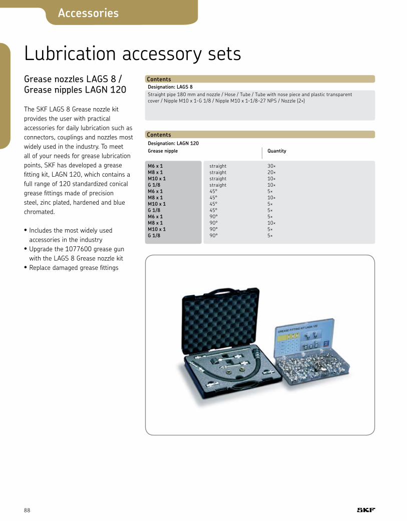
88
Accessories
Lubrication accessory setsGrease nozzles LAGS 8 /Grease nipples LAGN 120
The SKF LAGS 8 Grease nozzle kit provides the user with practical accessories for daily lubrication such as connectors, couplings and nozzles most widely used in the industry. To meet all of your needs for grease lubrication points, SKF has developed a grease fitting kit, LAGN 120, which contains a full range of 120 standardized conical grease fittings made of precision steel, zinc plated, hardened and blue chromated.
• Includes the most widely used accessories in the industry
• Upgrade the 1077600 grease gun with the LAGS 8 Grease nozzle kit
• Replace damaged grease fittings
ContentsDesignation: LAGS 8Straight pipe 180 mm and nozzle / Hose / Tube / Tube with nose piece and plastic transparent cover / Nipple M10 x 1-G 1/8 / Nipple M10 x 1-1/8-27 NPS / Nozzle (2×)
ContentsDesignation: LAGN 120Grease nipple Quantity
M6 x 1 straight 30× M8 x 1 straight 20× M10 x 1 straight 10× G 1/8 straight 10× M6 x 1 45° 5× M8 x 1 45° 10× M10 x 1 45° 5× G 1/8 45° 5× M6 x 1 90° 5× M8 x 1 90° 10× M10 x 1 90° 5× G 1/8 90° 5×
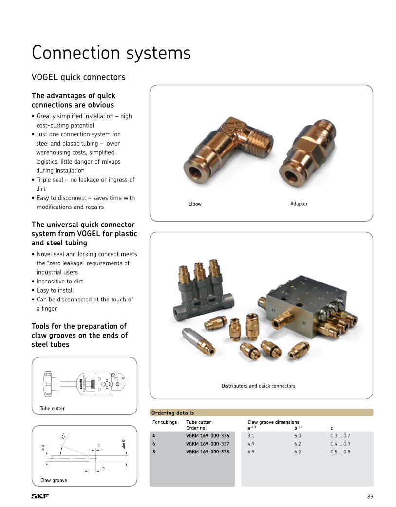
89
Connection systemsVOGEL quick connectors
The advantages of quick connections are obvious• Greatly simplified installation – high
cost-cutting potential• Just one connection system for
steel and plastic tubing – lower warehousing costs, simplified logistics, little danger of mixups during installation
• Triple seal – no leakage or ingress of dirt
• Easy to disconnect – saves time with modifications and repairs
The universal quick connector system from VOGEL for plastic and steel tubing• Novel seal and locking concept meets
the “zero leakage” requirements of industrial users
• Insensitive to dirt• Easy to install• Can be disconnected at the touch of
a finger
Tools for the preparation of claw grooves on the ends of steel tubes
Elbow Adapter
Distributors and quick connectors
Ordering detailsFor tubings Tube cutter Claw groove dimensions Order no. a+0.3 b±0.2 c
4 VGKM 169-000-336 3.1 5.0 0.3 ... 0.7
6 VGKM 169-000-337 4.9 6.2 0.4 ... 0.9
8 VGKM 169-000-338 6.9 6.2 0.5 ... 0.9
Tube cutter
Claw groove

90
Accessories
Ordering details (Adapters with cylindrical thread)Order no. Tube ØA G D ØB ØC L WAF 1 WAF 2 Seal
VGKA 404-003-VS 4 M8 x 1 6 8.8 11.5 23.8 10 2.5 NBR
VGKA 404-006-VS 4 M10 x 1 6 8.8 13.5 23.8 12 2.5 NBR
VGKA 404-006-S8-VS 4 M10 x 1 6 8.8 13.5 23.8 12 2.5 FKM (FPM)
VGKA 404-040-VS 4 G 1/8 6 8.8 13.5 23.8 12 2.5 NBR
VGKA 406-158-VS 6 M8 x 1 6 11.7 13.2 30.5 12 3 NBR
VGKA 406-004-VS 6 M10 x 1 6 11.7 13.5 27 12 4 NBR
VGKA 406-004-S8-VS 6 M10 x 1 6 11.7 13.5 27 12 4 FKM (FPM)
VGKA 456-004-VS 6 G 1/8 6 11.7 13.5 27 12 4 NBR
VGKA 406-162-VS 6 M12 x 1 7 11.7 15.4 28 14 4 NBR
VGKA 406-162-S8-VS 6 M12 x 1 7 11.7 15.4 28 14 4 FKM (FPM)
VGKA 408-004-VS 8 M10 x 1 6 13.9 15.2 32.3 14 5 NBR
VGKA 408-004-S8-VS 8 M10 x 1 6 13.9 15.2 32.3 14 5 FKM (FPM)
VGKA 408-162-VS 8 M12 x 1 7 13.9 15.2 32.8 14 6 NBR
VGKA 408-162-S8-VS 8 M12 x 1 7 13.9 15.2 32.8 14 6 FKM (FPM)
Ordering details (Adapters with tapered thread)Order no. Tube ØA G D ØB ØC L SW 1 SW 2
VGKA 451-004-462-VS 4 M6 tap. 5.5 8 11 25.8 10 2.5
VGKA 451-004-498-VS 4 M8 x 1 tap. 5 8.8 11.5 23.3 10 2.5
VGKA 451-004-518-VS 4 M10 x 1 tap. 5.5 8.8 11.5 22.8 10 2.5
VGKA 404-673K-V1-VS 4 1/4-28 SAE LT 5.1 8.8 11.5 26.3 10 2.5
VGKA 404-040K-V1-VS 4 1/8 NPTF 8 8.8 11.5 24.8 10 2.5
VGKA 451-006-468-VS 6 M6 tap. 5.5 11.7 13.5 30 12 2.5
VGKA 451-006-498-VS 6 M8 x 1 tap. 5.5 11.7 13.5 29.5 12 4
VGKA 451-006-518-VS 6 M10 x 1 tap. 5.5 11.7 13.5 27 12 4
VGKA 406-423W-VS 6 R 1/8 tap. 6.5 11.7 13.5 28.5 12 4
Adapter with cylindrical thread Adapter with tapered thread

91
Ordering details (Banjo fittings with cylindrical thread)Order no. Tube ØA G D ØB L1 L2 WAF 1 WAF 2 Seal
VGKA 504-101-VS 4 M8 x 1 6 10 21.8 20.5 10 9 NBR
VGKA 504-102-VS 4 M10 x 1 6 10 21.8 20.5 12 9 NBR
VGKA 504-108-VS 4 G 1/8 6 10 21.8 20.5 12 9 NBR
VGKA 506-139-VS 6 M8 x 1 6 12.5 26 21 10 10 NBR
VGKA 506-140-VS 6 M10 x 1 6 12.5 26 21 12 10 NBR
VGKA 506-140-S8-VS 6 M10 x 1 6 12.5 26 21 10 10 FKM (FPM)
VGKA 506-108-VS 6 G 1/8 6 12.5 26 21 12 10 NBR
VGKA 506-142-VS 6 M12 x 1 7 12.5 26 23 14 10 NBR
VGKA 506-142-S8-VS 6 M12 x 1 7 12.5 26 23 14 10 FKM (FPM)
VGKA 508-142-VS 8 M12 x 1 7 14.5 28.8 23 14 12 NBR
VGKA 508-142-S8-VS 8 M12 x 1 7 14.5 28.8 23 14 12 FKM (FPM)
Ordering details (Banjo fittings with tapered thread)Order no. Tube ØA G D ØB L1 L2 WAF 1 WAF 2
VGKA 455-546-048-VS 4 M6 tap. 6 10 21.8 20 10 9
VGKA 455-529-048-VS 4 M8 x 1 tap. 6 10 21.8 20 10 9
VGKA 455-531-048-VS 4 M10 x 1 tap. 6 10 21.8 20 12 9
VGKA 455-529-068-VS 6 M8 x 1 tap. 6 12.5 26 20 10 10
VGKA 455-531-068-VS 6 M10 x 1 tap. 6 12.5 26 20.5 12 10
Ordering details (Elbows with tapered thread)Order no. Tube ØA G D ØB L1 L2 WAF
VGKA 453-004-471-VS 4 M6 tap. 6 10 21.8 14 9
VGKA 504-201-VS 4 M8 x 1 tap. 6 10 21.8 13.5 9
VGKA 504-202-VS 4 M10 x 1 tap. 6 10 21.8 13.5 9
VGKA 514-018-VS 4 R 1/8 tap. 7.5 10 21.8 15 9
VGKA 504-200K-V1-VS 4 1/4-28 SAE LT 5.1 10 21.8 15.5 9
VGKA 514-018K-V1-VS 4 1/8 NPTF 7 10 21.8 15 9
VGKA 453-006-468-VS 6 M6 tap. 6 12.5 26 15 10
VGKA 506-508-VS 6 M8 x 1 tap. 6.5 12.5 26 14 10
VGKA 506-510-VS 6 M10 x 1 tap. 6 12.5 26 14 10
VGKA 508-511-VS 6 R 1/8 tap. 8.5 14.5 26 16.5 10
Banjo fittings with cylindrical thread Banjo fittings with tapered thread Elbows with tapered thread

92
Accessories
Fittings and accessories Steel and plastic tubing
Ordering details (Steel tubing) Minimum bending radius r Design Burst Ø da s Bent with Bent with pressure pressureOrder no. ±0.05 ±0.03 mandrel grooved disk [bars] [bars]
VGMD WV-RO2.5x0.5 VERZI 2.5 0.5 5 - 580 1410
VGMD WV-RO4x0.7 VERZI 4 0.7 8 7 500 1220
VGMD WV-RO6x0.7 VERZI 6 0.7 25 12 320 850
VGMD WV-RO8x0.7 VERZI 8 0.7 46 19 230 675
VGMD WV-RO10x1 VERZI 10* 1 76 27 270 660
* øda ± 0.07VERZI = 25 µm galvanization - yellow passivated. Length delivered 5 m. Stainless steel tubing on request.
Ordering details (Plastic tubing) Smallest permissible Perm. BurstOrder no. 1) Ø da s Ø di bending radius r bent operating pressure +0.15 free-hand with fixture2) pressure3) [bars] -0.05 [bars]
VGMA WVN715-RO2.5x0.5 2.5 0.5 1.5 25 9 66 198
VGMA WVN715-RO4x0.85 4 0.85 2.3 38 14 72 216
VGMA WVN715-RO6x1 6 (±0.1) 1 4 63 21 53 159
VGMA WVN715-RO6x1.25 6 1.25 3.5 63 21 70 210
VGMA WVN715-RO8x1.25 8 1.25 5.5 76 28 49 147
VGMA WVN715-RO10x1.5 10 1.5 7 89 35 47 141
VGMA WVN715-RO12x1 12 (±0.15) 1 10 110 45 24 72
VGMA WVN715-RO12x1.5 12 1.5 9 110 45 38 114
VGMA WVN716-RO4x0.85 4 0.85 2.3 38 14 36 108
VGMA WVN716-RO6x1.25 6 (±0.1) 1.25 3.5 63 21 35 105
VGMA WVN716-RO8x1.25 8 1.25 5.5 80 30 25 75
Plastic tubing: VGMA WVN715, without plasticizer VGMA WVN716, flexible (containing plasticizer)
Color: natural colors, black lettering. Tubing available in green, red, black or brown on request.Tubing with other dimensions or also filled with NLGI grade 2 grease or fluid grease on request.
Important! For screwed tubing joints, only use unions with reinforcing sockets.
Material VGMA WVN715: optionally polyamide 11 (PA 11) without plasticizer or polyamide 12 (PA 12) without plasticizer to DIN 73378.PA 12 H: polyamide 12 without plasticizer, stabilized against thermal aging.(black tubing) PA 12 HL: polyamide 12 without plasticizer, stabilized against light-related and thermal aging.
Material VGMA WVN716: optionally polyamide 11 (PA 11) flexible or polyamide 12 (PA 12) flexible to DIN 73378.
PA 12 PH: polyamide 12 with plasticizer, stabilized against thermal aging.(black tubing) PA 12 PHL: polyamide 12 with plasticizer, stabilized against light-related and thermal aging.
Material properties: Very good resistance and insensitivity to oils, greases, lubricants, all fuels, chlorine-free detergents and solvents.At room temperature good resistance to diluted mineral acids, organic acids, bases and saline solutions 4).Inappropriate for concentrated mineral acids, concentrated acetic acid, phenols, cresols, chlorinated hydrocarbons, chlorine, acetones and ketones.
Permissible operating temperature: approximately –60° C to +80° C (-76° to +176° F)1) The desired length. e.g. 50 meters, has to be
added to the order No. Ordering example: VGMA WVN716-RO6x1.25x50M
2) These minimal radii can be produced with the help of appropriate bending devices.
The tubing has to be heated to 66° C (150° F) for this purpose - maximum duration of heating is 20 seconds.
3) The operating pressures were ascertained in keeping with DIN 73378 to the formula 20 · sV · s (rated) P = ––––––––––––– dm
s = rated wall thickness [mm]; dm = da – s; sV = reference tension N / mm2 at 23° C (73° F) At higher temperatures, the pressure drops in keeping with the pressure efficiency as per DIN 73378.
Temperature range Pressure efficiency[°C / °F] [%]
up to 30° C / 86° F 83up to 40° C / 104° F 72up to 50° C / 122° F 64up to 60° C / 140° F 57up to 70° C / 158° F 52up to 80° C / 176° F 47
4) In borderline cases, consult SKF before ordering.
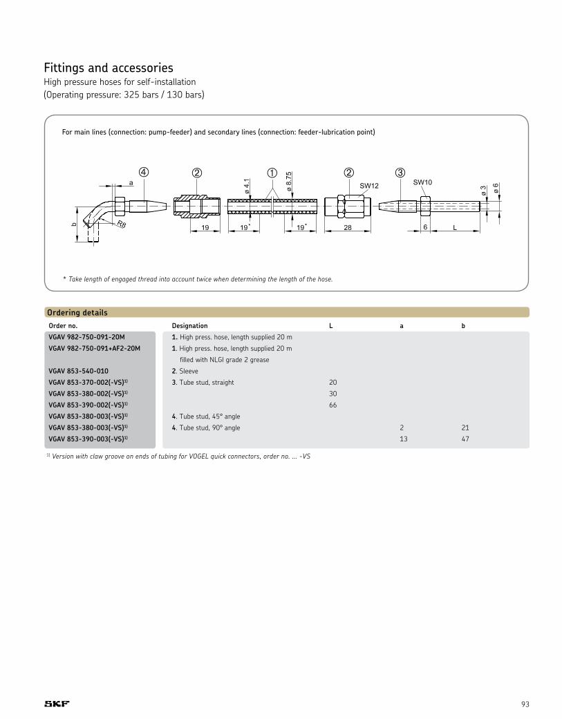
93
Fittings and accessories High pressure hoses for self-installation (Operating pressure: 325 bars / 130 bars)
Ordering detailsOrder no. Designation L a b
VGAV 982-750-091-20M 1. High press. hose, length supplied 20 m
VGAV 982-750-091+AF2-20M 1. High press. hose, length supplied 20 m
filled with NLGI grade 2 grease
VGAV 853-540-010 2. Sleeve
VGAV 853-370-002(-VS)1) 3. Tube stud, straight 20
VGAV 853-380-002(-VS)1) 30
VGAV 853-390-002(-VS)1) 66
VGAV 853-380-003(-VS)1) 4. Tube stud, 45° angle
VGAV 853-380-003(-VS)1) 4. Tube stud, 90° angle 2 21
VGAV 853-390-003(-VS)1) 13 47
1) Version with claw groove on ends of tubing for VOGEL quick connectors, order no. ... -VS
* Take length of engaged thread into account twice when determining the length of the hose.
For main lines (connection: pump-feeder) and secondary lines (connection: feeder-lubrication point)

94
Accessories
Electric plug-and-socket connectorsSockets for pressure switches, level switches, flow sensors, directional control valves and filters
Electric plugs or sockets are required for the actuation of various models of hydraulic equipment used in the field of central lubrication technology and for the evaluation of switching signals. DIN EN 175301-803/ISO 4400 M12 x 1
Ordering detailsOrder no. Standard design/type Application Pressure Flow Filter Lubricant Piston Oil-streak Flow Cycle switch sensor monitor level switch distributor sensor monitor switch
VGNB 179-990-034 DIN EN 175301-803/ ISO4400 • • • •
VGNB 179-990-371 straight 4-pole type, M12 x 1
• • • • • • • •
VGNB 179-990-372 angled • • • • • • • •
VGNB 179-990-600 straight 4-pole type, M12 x 1 • • • • • • • •
VGNB 179-990-601 angled (with integrally extruded line) • • • • • • • •
Ordering detailsOrder no. VGNB 179-990-034
Version Insert rotatable 4 x 90°
Poles 3 + PE
Operating display –
Maximum rated operating voltage 230 V AC/DC
Maximum operating current 10 A
Housing PA, black
Approval UL-SEV
Cable gland PG 11 / PG 9*
Conductor cross section max. 1.5 mm2
Line diameter 6 to 9 mm / 4.5 to 7 mm
Type of terminal Screws
IP enclosure DIN 40050 IP 65 (installed)
Temperature range -40° to +80° C
Seal Attached, NBR
SocketTo DIN EN 175301-803/ISO 4400supplied with flat packing and fixing screw
2
1
3
Circuit diagram
* PG = heavy gauge conduit thread
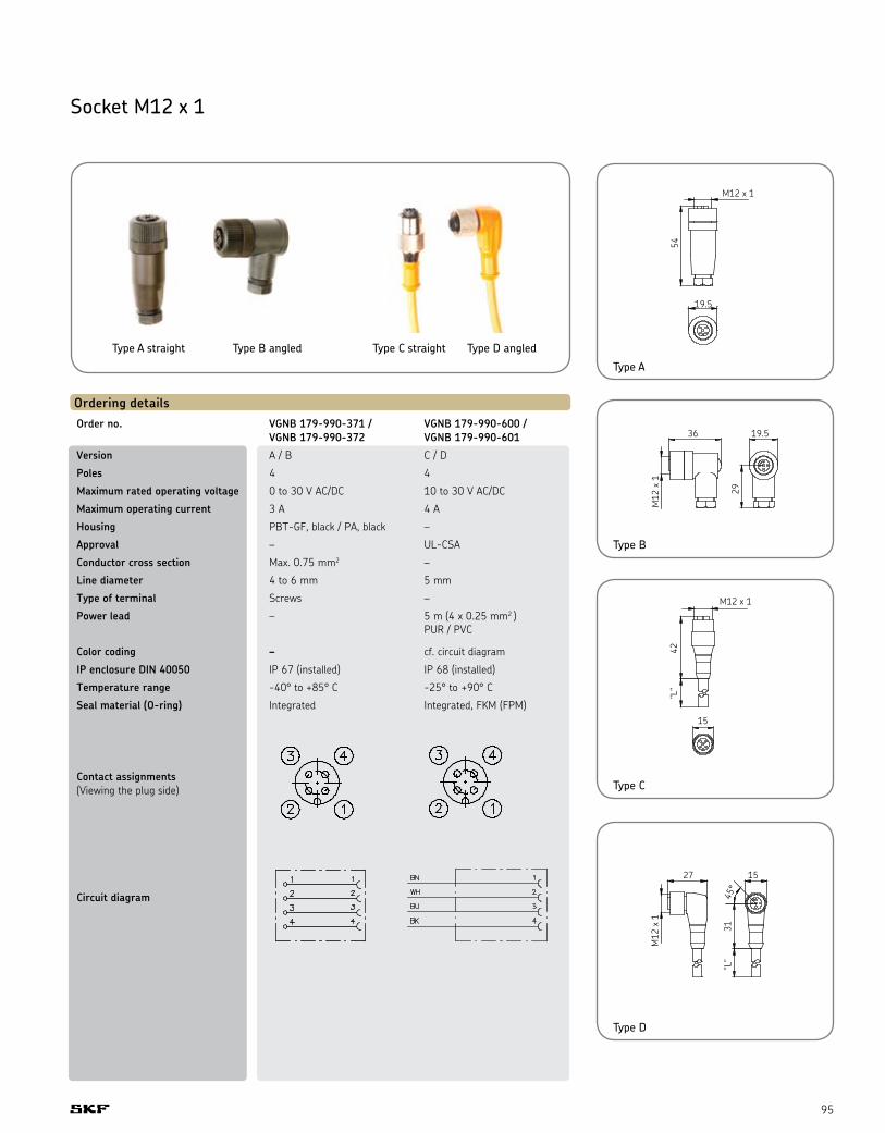
95
Socket M12 x 1
Type A straight Type B angled Type C straight Type D angled
Ordering detailsOrder no. VGNB 179-990-371 / VGNB 179-990-600 / VGNB 179-990-372 VGNB 179-990-601
Version A / B C / D
Poles 4 4
Maximum rated operating voltage 0 to 30 V AC/DC 10 to 30 V AC/DC
Maximum operating current 3 A 4 A
Housing PBT-GF, black / PA, black –
Approval – UL-CSA
Conductor cross section Max. 0.75 mm2 –
Line diameter 4 to 6 mm 5 mm
Type of terminal Screws –
Power lead – 5 m (4 x 0.25 mm2 )
PUR / PVC
Color coding – cf. circuit diagram
IP enclosure DIN 40050 IP 67 (installed) IP 68 (installed)
Temperature range -40° to +85° C -25° to +90° C
Seal material (O-ring) Integrated Integrated, FKM (FPM)
Contact assignments (Viewing the plug side)
Circuit diagram
Type A
Type B
Type C
Type D
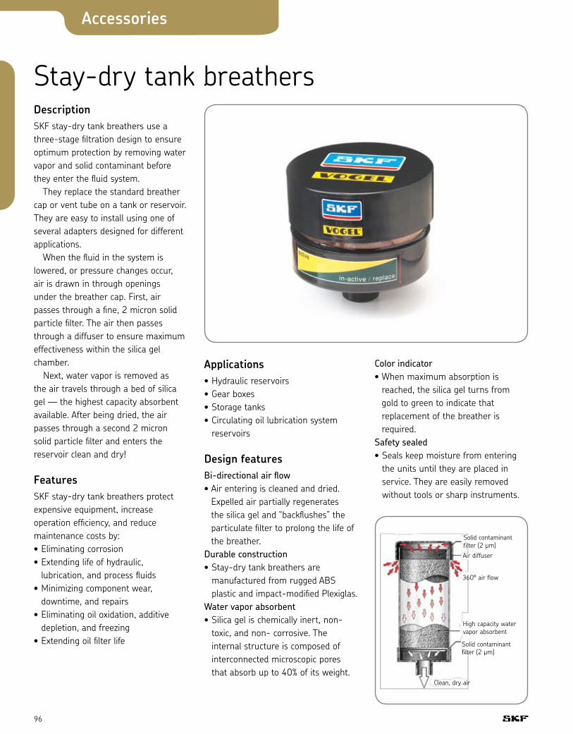
96
Accessories
Stay-dry tank breathersDescription SKF stay-dry tank breathers use a three-stage filtration design to ensure optimum protection by removing water vapor and solid contaminant before they enter the fluid system. They replace the standard breather cap or vent tube on a tank or reservoir. They are easy to install using one of several adapters designed for different applications. When the fluid in the system is lowered, or pressure changes occur, air is drawn in through openings under the breather cap. First, air passes through a fine, 2 micron solid particle filter. The air then passes through a diffuser to ensure maximum effectiveness within the silica gel chamber. Next, water vapor is removed as the air travels through a bed of silica gel — the highest capacity absorbent available. After being dried, the air passes through a second 2 micron solid particle filter and enters the reservoir clean and dry!
FeaturesSKF stay-dry tank breathers protect expensive equipment, increase operation efficiency, and reduce maintenance costs by: • Eliminating corrosion • Extending life of hydraulic,
lubrication, and process fluids • Minimizing component wear,
downtime, and repairs • Eliminating oil oxidation, additive
depletion, and freezing • Extending oil filter life
Applications• Hydraulic reservoirs • Gear boxes • Storage tanks• Circulating oil lubrication system
reservoirs
Design featuresBi-directional air flow • Air entering is cleaned and dried.
Expelled air partially regenerates the silica gel and “backflushes” the particulate filter to prolong the life of the breather.
Durable construction • Stay-dry tank breathers are
manufactured from rugged ABS plastic and impact-modified Plexiglas.
Water vapor absorbent • Silica gel is chemically inert, non-
toxic, and non- corrosive. The internal structure is composed of interconnected microscopic pores that absorb up to 40% of its weight.
Color indicator • When maximum absorption is
reached, the silica gel turns from gold to green to indicate that replacement of the breather is required.
Safety sealed • Seals keep moisture from entering
the units until they are placed in service. They are easily removed without tools or sharp instruments.
Solid contaminant filter (2 µm)Air diffuser
360° air flow
High capacity water vapor absorbent
Solid contaminant filter (2 µm)
Clean, dry air

97
Ordering details (adapters sold separately)Part no. Height (A) Weight Max. H2O capacity inches (mm) lbs. (kg) lbs. (ltr)
VGHD 9822-610-002 3.5 (90) 1.3 (0.6) 0.2 (0.1)
VGHD 9822-610-003 5 (128) 1.9 (0.9) 0.4 (0.2)
VGHD 9822-610-004 8 (205) 3.3 (1.5) 0.9 (0.5)
VGHD 9822-610-005 10 (254) 4.9 (2.2) 1.3 (0.6)
Dimensions are for general information only, all critical dimensions should be verified by requesting a certified print. Dimensions are in inches (mm) and lbs. (kg).BD 100, 200, 400
standard 1" friction fit (see adapter selection guide)
BD 800 2" NPT only (no adapter needed)
A
Ø5" (128 mm)
1.25" (32 mm)
Adapter selection guide (adapters sold separately – Note: no adapter needed for BD 800)
Bayonet adapter Part no. VGHD-02074251
Threaded adapter Part no. VGHD-02074248 (3/4" NPT) Part no. VGHD-02074249 (1" NPT)
Threaded standpipe adapter Part no. VGHD-02077124
Flange adapter Part no. VGHD-02074250 (not drilled) Part no. VGHD-02075193 (pre-drilled)
Bayonet flange kit with 3.5" steel basket
Part no. VGHD-02079076
Bypass adapter Part no. VGHD-012708016
Adapter Part no. VGHD-02081637
Mounting hole position for pre-drilled adapter (Flange interface to DIN 24557/T2)
1" Friction fit1" Friction fit
gasket not provided
1 1/2-16 UN-2B Existing standpipe
1 Bayonet fitting
2 Gaskets
1 Filler basket
6 Screws for installation
1" Friction fit to breather
Vent to atmosphere
1" Friction fit to any adapter
1 1/4" NPT female
1" Friction fit
Ø 2.874" 73 mm
Ø 0.18" 4.5 mm (6 places)
Ø 2.36" 60 mm

98
Accessories
OilCheck monitor TMEH 1Detects changes in oil condition
The OilCheck measures the changes in dielectric constant of an oil. By comparing the measurements obtained from used and unused oils of the same type and brand, the SKF OilCheck is able to determine the degree of change in the condition of the oil. Dielectric change is directly related to the degradation and contamination level of the oil and will allow the user to achieve optimized intervals between oil changes and detect increased mechanical wear and loss of the oils lubricating properties. To facilitate trending, the instrument is equipped with a numerical read–out.
ImportantThe SKF OilCheck is not an analytical instrument. It is an instrument to detect only changes in the oil condition. The visual and numerical read–outs are purely a guide to enable trending of the comparative readings of a good oil to a used oil of the same type and brand. Do not rely solely on numerical readings.
• Shows changes in oil condition affected by such things as:
—Water content —Fuel contamination —Metallic content —Oxidation• Hand-held and user friendly• Numerical read–out to acilitate
trending
Handheld viscometer TMVM 1Reduce costly and time consuming laboratory analyses
The SKF viscometer TMVM 1 is a handheld rotational viscometer for quick and reliable viscosity measurements of lubrication oils and hydraulic fluids. It is suitable for both quantitative and qualitative measurements. The TMVM 1 is a first check device for carrying out on-site measurements. Regular viscosity checks help provide timely information regarding oil condition, which can have an effect on lubrication and machine performance.
• Compact light-weight design and portability of the viscometer make it an essential device for field service engineers and other field operators
• Supplied standard with a rotor suitable for a viscosity range between 30 and 1,300 MPas covering a majority of lubrication oils
• Ergonomic design makes it easy to operate with one hand
• Direct read out eliminates the need for further complex, time-consuming calculations
• Use of supplied measuring cup helps ensure reproducible measuring conditions for accurate measurements
• Excellent repeatability allowing reliable trending of oil condition
• Recalibration message displayed on the viscometer allows timely recalibration
• Alternative rotors available as accessories make viscosity measurement of other fluids possible
• Battery (4 x AA alkaline) operated, does not require a main electrical supply making it a convenient instrument for field tests
• Supplied in a sturdy carrying case for ease of portability

99
Portable filter cart Maintaining clean oil in an industrial environment is a key to machine performance and reliability. The SKF portable filter cart is a solution designed to meet this need. The unit can be used to clean new oil to a low level of contamination before it is introduced into the system or to clean oil in a reservoir with a minimum number of circulation passes. The SKF portable filter cart is designed to capture a large quantity of particulates because of the high retention capacity of the filter media and use of multiple, extended-length spin-on elements.
Features• Availability of water removal
elements with capacity of 0.45 quarts of water each
• Welded tubular steel frame for durability
• Dirt-tolerant, self-priming vane pump
• Compact design, balanced weight, and large tires for easy handling
• Color-coded gauge for warning about clogged filter elements
Applications• Filters particles and/or water from
new oil while filling a reservoir• Recirculates and filters oil during
start-up when contamination is often heaviest
• Recirculates and filters oil off-line on systems with inadequate filtering capacity
• Empties storage tanks or reservoirs• Ideal for use in industrial plants
and other demanding applications because of their efficiency, capacity, and durability
Ordering detailsStage 1 elements Stage 2 elements
003 3 micron absolute 003 3 micron absolute
005 6 micron absolute 005 6 micron absolute
010 10 micron absolute 010 10 micron absolute
020 20 micron absolute 020 20 micron absolute
010A 20 micron water removal 010A 20 micron water removal
Example: VGHV 9823 – 020 – 010
Note: Order two-stage filter cart number VGHA 9823-440-410 for use with high viscosity oils above ISO 100.For higher viscosity oils, make sure the oil is at 100 degrees Farenheit before filtering. This may require the use of a drum heater.
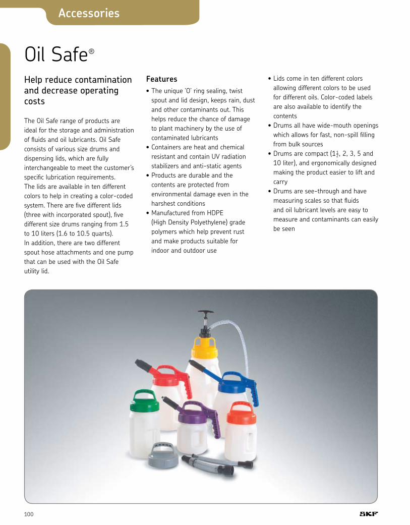
100
Accessories
Oil Safe®
Help reduce contamination and decrease operating costs
The Oil Safe range of products are ideal for the storage and administration of fluids and oil lubricants. Oil Safe consists of various size drums and dispensing lids, which are fully interchangeable to meet the customer’s specific lubrication requirements. The lids are available in ten different colors to help in creating a color-coded system. There are five different lids (three with incorporated spout), five different size drums ranging from 1.5 to 10 liters (1.6 to 10.5 quarts). In addition, there are two different spout hose attachments and one pump that can be used with the Oil Safe utility lid.
Features• The unique ‘O’ ring sealing, twist
spout and lid design, keeps rain, dust and other contaminants out. This helps reduce the chance of damage to plant machinery by the use of contaminated lubricants
• Containers are heat and chemical resistant and contain UV radiation stabilizers and anti-static agents
• Products are durable and the contents are protected from environmental damage even in the harshest conditions
• Manufactured from HDPE (High Density Polyethylene) grade polymers which help prevent rust and make products suitable for indoor and outdoor use
• Lids come in ten different colors allowing different colors to be used for different oils. Color-coded labels are also available to identify the contents
• Drums all have wide-mouth openings which allows for fast, non-spill filling from bulk sources
• Drums are compact (1½, 2, 3, 5 and 10 liter), and ergonomically designed making the product easier to lift and carry
• Drums are see-through and have measuring scales so that fluids and oil lubricant levels are easy to measure and contaminants can easily be seen
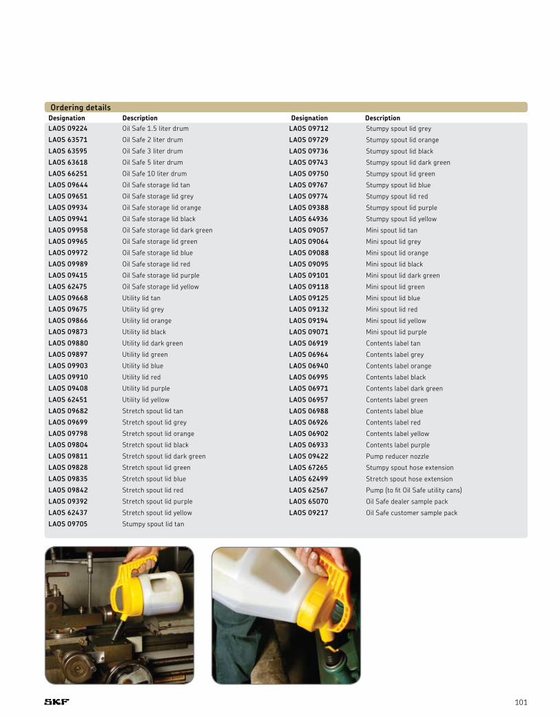
101
Designation Description Designation DescriptionLAOS 09224 Oil Safe 1.5 liter drum
LAOS 63571 Oil Safe 2 liter drum
LAOS 63595 Oil Safe 3 liter drum
LAOS 63618 Oil Safe 5 liter drum
LAOS 66251 Oil Safe 10 liter drum
LAOS 09644 Oil Safe storage lid tan
LAOS 09651 Oil Safe storage lid grey
LAOS 09934 Oil Safe storage lid orange
LAOS 09941 Oil Safe storage lid black
LAOS 09958 Oil Safe storage lid dark green
LAOS 09965 Oil Safe storage lid green
LAOS 09972 Oil Safe storage lid blue
LAOS 09989 Oil Safe storage lid red
LAOS 09415 Oil Safe storage lid purple
LAOS 62475 Oil Safe storage lid yellow
LAOS 09668 Utility lid tan
LAOS 09675 Utility lid grey
LAOS 09866 Utility lid orange
LAOS 09873 Utility lid black
LAOS 09880 Utility lid dark green
LAOS 09897 Utility lid green
LAOS 09903 Utility lid blue
LAOS 09910 Utility lid red
LAOS 09408 Utility lid purple
LAOS 62451 Utility lid yellow
LAOS 09682 Stretch spout lid tan
LAOS 09699 Stretch spout lid grey
LAOS 09798 Stretch spout lid orange
LAOS 09804 Stretch spout lid black
LAOS 09811 Stretch spout lid dark green
LAOS 09828 Stretch spout lid green
LAOS 09835 Stretch spout lid blue
LAOS 09842 Stretch spout lid red
LAOS 09392 Stretch spout lid purple
LAOS 62437 Stretch spout lid yellow
LAOS 09705 Stumpy spout lid tan
LAOS 09712 Stumpy spout lid grey
LAOS 09729 Stumpy spout lid orange
LAOS 09736 Stumpy spout lid black
LAOS 09743 Stumpy spout lid dark green
LAOS 09750 Stumpy spout lid green
LAOS 09767 Stumpy spout lid blue
LAOS 09774 Stumpy spout lid red
LAOS 09388 Stumpy spout lid purple
LAOS 64936 Stumpy spout lid yellow
LAOS 09057 Mini spout lid tan
LAOS 09064 Mini spout lid grey
LAOS 09088 Mini spout lid orange
LAOS 09095 Mini spout lid black
LAOS 09101 Mini spout lid dark green
LAOS 09118 Mini spout lid green
LAOS 09125 Mini spout lid blue
LAOS 09132 Mini spout lid red
LAOS 09194 Mini spout lid yellow
LAOS 09071 Mini spout lid purple
LAOS 06919 Contents label tan
LAOS 06964 Contents label grey
LAOS 06940 Contents label orange
LAOS 06995 Contents label black
LAOS 06971 Contents label dark green
LAOS 06957 Contents label green
LAOS 06988 Contents label blue
LAOS 06926 Contents label red
LAOS 06902 Contents label yellow
LAOS 06933 Contents label purple
LAOS 09422 Pump reducer nozzle
LAOS 67265 Stumpy spout hose extension
LAOS 62499 Stretch spout hose extension
LAOS 62567 Pump (to fit Oil Safe utility cans)
LAOS 65070 Oil Safe dealer sample pack
LAOS 09217 Oil Safe customer sample pack
Ordering details

102
Accessories
Technical data Designation TMBA G11DPack size 50 pairs Size 9 Color white
TMBA G11D (page 82)
Designation LAGF 18 LAGF 50Maximum pressure 3 MPa (430 psi) 3 MPa (430 psi) Volume / stroke Approximately 45 cm3 (1.5 fl oz.) Approximately 45 cm3 (1.5 fl oz.) Suitable drum dimensions: – Inside diameter 265 – 285 mm (10.4 – 11.2 in) 350 – 385 mm (13.8 – 15.2 in) – Maximum inside height 420 mm (16.5 in) 675 mm (26.6 in) Weight 5 kg (11 lb) 7 kg (15 lb)
LAGF series (page 82)
Designation LAGG 18M LAGG 18AE LAGG 50AE LAGG 180AE LAGT 180 Description Grease pump Mobile grease pump Grease pump Grease pump Trolley for drums for 18 kg drums for 18 kg drums for 50 kg drums for 180 kg drums up to 200 kg Pumping Manual Air–pressure Air–pressure Air–pressure – Maximum pressure 50 MPa (7,250 psi) 42 MPa (6,090 psi) 42 MPa (6,090 psi) 42 MPa (6,090 psi) – SKF Drum 18 kg (39.6 lb) 18 kg (39.6 lb) 50 kg (110 lb) 180 kg (396 lb) 180 kg (396 lb) Inner diameter 265 – 285 mm 265 – 285 mm 350 – 385 mm 550 – 590 mm – (10.43 – 11.22 in) (10.43 – 11.22 in) (13.78 – 15.16 in) (21.65 – 23.23 in) Note Stationary Mobile Stationary Stationary Mobile Volume / stroke 1.6 cc – – – – Volume / minimum – 200 cc 200 cc 200 cc –
LAGG series (page 83)
Designation LAGG 1MBody pump material Polypropylene / Polyethylene, compatible with all SKF greases Follower plate material NBR, compatible with all SKF greases Weight 230 g (0.5 lb) Volume per stroke 26 cm3 (1.6 in3)
LAGG 1M (page 83)
Suitable can dimensions: Inside diameter 105 – 108 mm (4.1 – 4.25 in) Maximum inside height 145 mm (5.7 in) Suitable greases consistencies NLGI 1 to 3
GSE series (page 84)
Number of outlets 1 to 6 Delivery rate (per stroke) Piston Ø6 Adjustable from 0 to 0.08 cm3
Piston Ø8 Adjustable from 0 to 0.15 cm3 Number of stroke 15 / min Pressure maximum 250 bar Outlet connection Orientable, drilling for connectors with double tapered sleeves for tubes Ø6 or 8 Drain plug H 14 Minimum level control Pressure switch with connector, set at 0.5 bar Operating temperature -10° C to +40° C Lubricant viscosity (at operating temperature) Grease Up to NLGI grade 2 Oil 100 to 2000 mm2/s Start up To make the start up easier fill up the pump housing via the drain plug (4) Material Pump element Treated steel and brass Housing Steel Suction pipe Steel
Electrical data
Electric motor Three Single Direct phase phase current Class F / vented F / vented not vented Voltage 230 / 400 V 230 V 24 V DC Frequency 50 / 60 Hz** 50 / 60 Hz** – Power 90 W 90 W 90 W Protection IP 55 IP 55 IP 54 Rotation speed 1,500 rpm 1,500 rpm 1,500 rpm Current 230 V 0.59 A 0.89 A – Current 400 V 0.34 A – – Current 24 V DC – – 5 A Level control Minimal Switching capacity 250 V / 4A Voltage maximum 250 V Current maximum 0.5 A Type of enclosure IP 65 Connector DIN 43650 Cable gland PG9
** At 60 Hz rotation speed is multiplied by 1.2

103
Designation LAGN 120Maximum working pressure 40 MPa (5 800 psi) Minimum burst pressure 80 MPa (11 600 psi)
LAGN 120 (page 88)
Standard DIN 71412 Material Hardened steel
Hose Operating pressure 325 bars Burst pressure 800 bars Minimum bending radius 35 mm
Materials Hose Inner lining: unplasticized polyester Liner layer: braided synthetic fibers Outer cover: weatherproof polyurethane Sleeve, tube stud: steel, galvanized
High pressure hoses for self-installation (page 93)
PTEX extruder pumps (page 86)
Main data Air consumption 900NI / min Air inlet pressure 3 to 8 bars
Pump ratio 55 : 1 Pump delivery rate (at 6 bars) Pump A 0.83 kg / mn Pump B 0.5 kg / mn Lubricant Greases NLGI grades 000 to 2 Operating temperature +10° C to +50° C Air inlet G 3/8
Position detector, reed switch type Maximum switching power 6 W Switching voltage 10 to 30 V DC and AC
Maximum switching current 200 mA Contact resistance 0.15 Ω maximum Insulation resistance > 100 MΩ Withstand voltage 200 V DC Sensitivity 2.5 mTesla minimum (25 gauss) Repeatability ± 0.5 mm Operating temperature -15° C to +70° C Degree of protection (CE I 529) IP67 Signal indication Orange diode (LED) which lights up when the contact is established
Connector 3-pin plug-in male connector, ØM8
Cable PVC, Lg 0.15 m
General air solenoid valve Type 3 / 2 NC Connection G 3/8
Electric connection PG9 Delivery rate 2700 NI/mn Operating pressure 0 to 8 bars Operating voltage 24 V DC Degree of protection IP65
Lubricant pressure switch Max. operating voltage 250 V AC Degree of protection IP65
Setting range 10 to 100 bars Adm. pressure Maximum 300 bars Electric connection PG9 Factory setting None
Maximum operating 300 bars (metal pressure tube with claw groove) Maximum operating -40° C to +80° C temperature Medium Oils, grease up to NGLI grade 2 Connection Detachable Material Brass Suitable for steel tubing with claw groove and for plastic tubing
Quick connectors (page 89)
Designation TMEH 1Suitable oil types Mineral and synthetic oils Repeatability Better than 5% Read-out Green / red grading + numerical value (0 – 100)
TMEH 1 (page 98)
Battery 9V alkaline IEC 6LR61 Battery lifetime > 150 hours or 3 000 tests Dimensions 250 × 95 × 32 mm (instrument) (9.8 × 3.7 × 1.3 in)

104
Accessories
Portable filter cart (page 99)
Fluid compatibility Mineral oil, including lube and fuel oil (Note: Not allowed for use on water-based fluids) Motor 1750 rpm, 3/4 HP, 110 V single phase Electric cord 20 ft. long Pump Direct drive vane, 10 gpm, self-priming 3, 5, 10 and 20 micron, absolute-rated filters extended length spin-on, with 25 psi (1.7 bar) bypass 10 micron absolute, water removal filters extended length spin-on, approximately 0.45 quarts of water capacity, with 25 psi (1.7 bar) bypass Clogging indicators Color-coded static pressure gauge
Strainer Stainless steel, 520 µm Hoses Spiral-reinforced clear PVC, standard 10 ft. length 20 in. spiral wands Dimensions Height 51" Width 21.5" Length 27.5" Weight of cart with elements 123 lbs. Operating range Fluid temperature 50° F to 130° F (10° C to 54° C)
Pressure to 87 psi (6 bar) Viscosity 100 - 500 SUS
Designation TMVM 1Description Handheld viscometer Dynamic viscosity range (MPas) 30-1300 with Rotor 3 (30 - 400.000 using optional rotors) Motor rated voltage 4.0 VD C Motor rated speed 62.5 rpm Rotor supplied R3 Repeatability < 1 % of total range Accuracy ± 3 % of total range with supplied rotor R3 Operating temperature 10° C to 40 ° C (50° F to 104° F) Oil sample volume Approx. 150 ml (5.1 fl.oz.) Viscometer dimension (w x d x h) 175 x 88 x 170 mm (6.8 x 3.4 x 6.6 in) Rotor dimension D = 45.1 mm (1.7 in) h = 47 mm (1.8 in) Rotor material Stainless steel Measuring cup dimension D = 52.6 mm (2.0 in) h = 75 mm (2.9in) Measuring cup material Stainless steel Battery 4 x AA (IEC type LR06) alkaline Total weight (including case) 2.0 kg (4.4 lbs) Packaging Sturdy carrying case Certificate of calibration Yes
TMVM 1 (page 98)

105
Index
1077600 Grease gun 31 35352-…-K Metering nipples for piston distributors 74 –391-…-K Metering nipples for piston distributors 75 –995-994-… Metering nipples for piston distributors 74 –LAGD 60 Single-point lubricator 38 48LAGD 125 Single-point lubricator 38 48LAGD 400 MultiPoint automatic lubricator 44 48LAGD 1000 MultiPoint automatic lubricator 53 78LAGE 125 Single-point lubricator 40 48LAGE 250 Single-point lubricator 40 48LAGF Grease filler pumps 82 102LAGG Battery driven grease gun 32 35LAGG Grease pumps 83 102LAGH One-hand operated grease gun 31 35LAGM Grease meter 34 36LAGN Grease nipple set 88 103LAGP Grease packer 30 35LAGS Grease nozzle set 88 –LAHD Oil leveller 45 49LAOS Oil Safe containers, lids, labels 100 –LAPA Angle connectors 42 42LAPB Single-point lubricator brushes 42 42LAPC Single-point lubricator clamp 42 42LAPE Single-point lubricator extension pipe 42 42LAPF Tube connectors 42 42LAPG Grease nipple 42 42LAPM Y connection / manifold 42 42LAPP Protective base / cover 42 42LAPT Single-point lubricator flexible tube 42 42LAPV Non return valves 42 42LDTS Dry lubricant for tabletop chain 21 21LGAF Anti-fretting agent 22 23LGAP All-purpose grease 11 24LGEL Extreme pressure grease 11 24LGEM Molydenum disulphide and graphite grease 14 28LGET Extreme temperature grease 13 27LGEV High viscosity molydenum and graphite grease 14 28LGFA Food applications grease 15 25LGGB Green biodegradable grease 15 27LGHB High viscosity grease 12 27LGHP High performance grease 12 26LGLT Low temperature grease 14 26LGMT General purpose grease 11 26LGWA Wide application grease 12 27LGWM Wind mill grease 13 28LHRP Anti-corrosive agent 22 23TMBA Disposable grease-resistant gloves 82 –TMEH OilCheck monitor 98 103TMVM Viscometer 98 104VGAA 342-4-… Piston distributors 74 –VGAA 343-4-… Piston distributors 74 –VGAA 345-4-… Piston distributors 74 –VGAA 351-0. Piston distributors 74 –
Series Description Page Tech Data
(continued on next page)

106
VGAA 352-0. Piston distributors 74 –VGAA 353-0. Piston distributors 74 –VGAA 391-0. Piston distributors 75 –VGAA 392-0. Piston distributors 75 –VGAA 393-0. Piston distributors 75 –VGAA VL-1-... Grease injectors 56 –VGAA VL-11-85497 Grease injectors 57 –VGAA VL-32-... Grease injectors 57 –VGAB VPBM-... Progressive feeders 33 –VGAB VSP... Modular progressive feeders 58 –VGAC 546-…-015-V1 Duoflex lubricant distributor 60 –VGAV 355-0 Piston distributors 74 –VGAV 853-…-… Tube studs 93 –VGAV 853-…-…-VS Tube studs with claw grooves 93 –VGAV 853-540-010 Sleeve 93 –VGAV 982-750-091 High pressure hose 93 103VGAV GS100 Drum pump elements 84 102VGAV GS1008 Drum pump follower plates 84 102VGAV KFA 1… Pump elements 54 78VGAV PT Drum pump covers 84 102VGBA MF Single-circuit pumps 64 –VGBB KFA Electrically powered mini pump units 54 78VGBB KFAS 1 Battery powered piston pump 55 78VGBB MKU Compact units for oil 72 –VGBE GSEO Drum pumps 84 102VGBL 169-000-146 Piston pump (gun only) 33 36VGBL PF-VPBM Piston pump with block feeder 33 36VGDA WS32-2 Level switches 67 79VGDA WS33-2 Level switches 67 79VGDA WS35-2 Level switches 67 79VGDC 171-210-... Flow monitors 76 79VGDC GS300 Flow sensors 76 79VGDC GS4011 Streak sensors 76 79VGDC GS6011 Streak sensors 76 79VGHD Tank breathers 96 –VGHD Tank Breather adapters 97 –VGHV 9823-…-… Portable filter carts 99 104VGKA 404-…-S8-VS Adapters with cylindrical threads 90 –VGKA 404-…-VS Adapters with cylindrical threads 90 –VGKA 404-…K-V1-VS Adapters with tapered threads 90 –VGKA 406-…-S8-VS Adapters with cylindrical threads 90 –VGKA 406-…-…-VS Adapters with cylindrical threads 90 –VGKA 406-…W-VS Adapters with tapered threads 90 –VGKA 408-…-S8-VS Adapters with cylindrical threads 90 –VGKA 408-…-…-VS Adapters with cylindrical threads 90 –VGKA 451-…-…-VS Adapters with tapered threads 90 –VGKA 453-…-…-VS Elbows with tapered threads 91 –VGKA 455-004-…-VS Elbows with tapered threads 91 –VGKA 455-…-…-VS Banjo fittings with tapered threads 91 –VGKA 456-…-VS Adapters with cylindrical threads 90 –VGKA 504-200-VS Elbows with tapered threads 91 –VGKA 504-…-VS Banjo fittings with cylindrical threads 91 –VGKA 504-…K-V1-VS Elbows with tapered threads 91 –VGKA 506-500-VS Elbows with tapered threads 91 –VGKA 506-…-S8-VS Banjo fittings with cylindrical threads 91 –VGKA 506-…-VS Banjo fittings with cylindrical threads 91 –VGKA 508-500-VS Elbows with tapered threads 91 –VGKA 508-…-S8-VS Banjo fittings with cylindrical threads 91 –
Series Description Page Tech Data
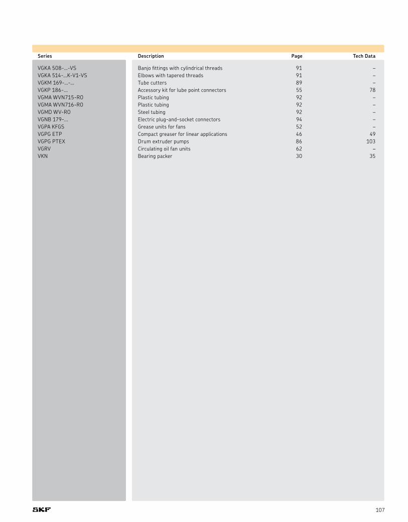
107
Series Description Page Tech Data
VGKA 508-…-VS Banjo fittings with cylindrical threads 91 –VGKA 514-…K-V1-VS Elbows with tapered threads 91 –VGKM 169-…-… Tube cutters 89 –VGKP 186-... Accessory kit for lube point connectors 55 78VGMA WVN715-RO Plastic tubing 92 –VGMA WVN716-RO Plastic tubing 92 –VGMD WV-RO Steel tubing 92 –VGNB 179-... Electric plug-and-socket connectors 94 –VGPA KFGS Grease units for fans 52 –VGPG ETP Compact greaser for linear applications 46 49VGPG PTEX Drum extruder pumps 86 103VGRV Circulating oil fan units 62 –VKN Bearing packer 30 35

108

SKF lubrication products and systemsThe industry’s most complete resource for knowledge-engineered lubrication solutions
SKF lubrication products and systems
® SKF, Vogel, SYSTEM 24, DialSet and OilSafe are registered trademarks of SKF USA Inc.® Safematic is a registered trademark of the John Crane Safematic Oy Company Finland.Safeflow is a trademark of SKF Group. Duoflex is a trademark of SKF USA Inc.The contents of this publication are the copyright of the publisher and may not be reproduced (even extracts) unless prior written permission is granted.Every care has been taken to ensure the accuracy of the information contained in this publication but no liability can be accepted for any loss or damage whether direct, indirect or consequential arising out of use of the information contained herein.
© 2007 SKF USA Inc. Publication 750-900 (30M/CW 6/2008) Version 6/2008 Printed in U.S.A.
SKF USA Inc.Kulpsville, PA 19443, USA
(215) 513-4400
www.skfusa.com


