Table of Contents18EC36 : POWER ELECTRONICS AND INSTRUMENTATION .................................................... 1 A. COURSE INFORMATION ............................................................................................................. 1 1. Course Overview .............................................................................................................................. 1 2. Course Content ................................................................................................................................. 2 3. Course Material ................................................................................................................................ 3 4. Course Prerequisites ......................................................................................................................... 3 B. OBE PARAMETERS ...................................................................................................................... 3 1. Course Outcomes .............................................................................................................................. 3 2. Course Applications .......................................................................................................................... 4 3. Articulation Matrix ........................................................................................................................... 4 4. Mapping Justification ....................................................................................................................... 5 5. Curricular Gap and Content .............................................................................................................. 6 6. Content Beyond Syllabus ................................................................................................................. 6 C. COURSE ASSESSMENT ............................................................................................................... 6 1. Course Coverage .............................................................................................................................. 6 2. Continuous Internal Assessment (CIA) ............................................................................................ 7 D1. TEACHING PLAN - 1 .................................................................................................................. 7 Module - 1 ............................................................................................................................................ 7 Module – 2 ............................................................................................................................................ 9 E1. CIA EXAM – 1 ............................................................................................................................ 10 a. Model Question Paper - 1 ............................................................................................................... 10 b. Assignment -1 ................................................................................................................................. 11 D2. TEACHING PLAN - 2 ................................................................................................................ 14 Module – 3 .......................................................................................................................................... 14 Module – 4 .......................................................................................................................................... 16 E2. CIA EXAM – 2 ............................................................................................................................ 18 a. Model Question Paper - 2 ............................................................................................................... 18 b. Assignment – 2 ............................................................................................................................... 19 D3. TEACHING PLAN - 3 ................................................................................................................ 21 Module – 5 .......................................................................................................................................... 21 E3. CIA EXAM – 3 ............................................................................................................................ 23 a. Model Question Paper - 3 ............................................................................................................... 23 b. Assignment – 3 ............................................................................................................................... 23 1. University Model Question Paper .................................................................................................. 25 2. SEE Important Questions ............................................................................................................... 26
Note : Remove “Table of Content” before including in CP Book Each Course Plan shall be printed and made into a book with cover page Blooms Level in all sections match with A.2, only if you plan to teach / learn at higherlevels
Dept ECPrepared by Checked byApproved
SKIT Teaching Process Rev No.: 1.0Doc Code: SKIT.Ph5b1.F02 Date: 16-08-
A. COURSE INFORMATION1. Course OverviewDegree: BE Program: ECYear / Semester : 2/3 Academic Year: 2019-20
Course Title: POWER ELECTRONICS ANDINSTRUMENTATION
Course Code: 18EC36
Credit / L-T-P: 03/3-0-0 SEE Duration: 180 MinutesTotal ContactHours:
40 SEE Marks: 60 Marks
CIA Marks: 40 Assignment 1 / ModuleCourse Plan Author: Tejaswini M Sign Dt:Checked By: Sign Dt:
2. Course ContentModule
Module Content TeachingHours
ModuleConcepts
BloomsLevel
1 Introduction: History, Power Electronic Systems, PowerElectronic Converters and Applications. Thyristors: StaticAnode-Cathode characteristics and Gate characteristics ofSCR, Turn- ON methods, Turn-OFF mechanisms. Turn-OFFMethods: Natural and Forced Commutation – Class A andClass B types Gate Trigger Circuit: Resistance FiringCircuit, Resistance capacitance firing circuit. UnijunctionTransistor: Basic operation and UJT Firing Circuit
08 Thyristorsapplication L1,L2
2 Phase Controlled Converter: Control techniques, Single phase halfwave and full wave controlled rectifier with resistive and inductive loads,effect of freewheeling diode.Choppers: Chopper Classification, Basic Chopper operation: step-down,step-up and step-up/down choppers.
08Rectification
L1,L2,L3
3 Inverters: Classification, Single phase Half bridge and full bridgeinverters with R and RL load Switched Mode Power Supplies: Isolated Flyback Converter, IsolatedForward Converter.Principles of Measurement: Static Characteristics, Error inMeasurement, Types of Static Error. Multirange Ammeters, Multirange voltmeter.
08Converters
L1,L2,L3
4 Digital Voltmeter: Ramp Technique, Dual slope integratingType DVM, Direct Compensation type and Successive 08
VoltageMeasurement L1,L2
Dept ECPrepared by Checked byApproved
SKIT Teaching Process Rev No.: 1.0Doc Code: SKIT.Ph5b1.F02 Date: 16-08-
Approximations type DVM Digital Multimeter: DigitalFrequency Meter and Digital Measurement of Time, FunctionGenerator.Bridges: Measurement of resistance: Wheatstone’s Bridge,AC Bridges-Capacitance and Inductance Comparison bridge,Wien’s bridge.
Note: Identify a max of 2 Concepts per Module. Write 1 CO per concept.
2. Course ApplicationsSNo Application Area CO Level1 Used in control processes and application CO1 L22 Used in Temperature and Environmental Applications -Low cost weather sta-
tionCO2 L3
3 Measurement of pressure, temperature, flow or level in a chemical processplant
CO3 L3
4 Aid in electrochemical measurements for a variety of applications includingfood, agriculture, wastewater treatment, industrial processes
CO4 L3
5 Oscilloscopes are used to test CD/DVD and disk drive designs by measuringdisk performance, media noise and optical recording characteristics.
CO5 L3
6 generally used in designing, testing, troubleshooting, and repairing electronicor electroacoustic devices
CO6 L3
7 Used in medical imaging systems CO7 L38 The applications of pressure transducer mainly involve in altitude sensing CO8 L39 Transducer is used to measure the temperature of the air such that to control
the temperature of several control systems like air-conditioning, heating,ventilation
CO9 L3
10 Sensors used in real time applications CO10 L3Note: Write 1 or 2 applications per CO.
3. Articulation Matrix(CO – PO MAPPING)
- Course Outcomes Program Outcomes# COs PO
1PO2
PO3
PO4
PO5
PO6
PO7
PO8
PO9
PO10
PO11
PO12
Level
18EC36.1 Build and test circuits usingpower electronic devices.
3 2 - - - - - - - - - - L3
18EC36.2 Analyze and design controlledrectifier, DC to DC converters,DC to AC inverters and SMPS.
Title: Measurement and Errors,Ammeter,Voltmeter ApprTime:
16 Hrs
a Course Outcomes - Blooms- The student should be able to: - Level1 Describe the types of error in instrument measurement and calculate
the errorsCO1 L2
2 Explain the working And range extension of multitester CO2 L3
b Course Schedule - -Class
No Module Content CoveredCO Level
1 Definitions, Accuracy, Precision, C01 L22 Resolution and Significant Figures, Types of Errors, Measurement
error combinationsCO1 L2
3 DC Ammeter, Multirange Ammeter, The Ayrton Shunt or UniversalShunt,
CO2 L3
4 DC Ammeter, Multirange Ammeter, The Ayrton Shunt or UniversalShunt-problems
CO2 L3
5 Requirements of Shunt, Extending of Ammeter Ranges, RF Ammeter(Thermocouple), Limitations of Thermocouple
CO2 L3
6 Introduction, Basic Meter as a DC Voltmeter, CO2 L37 DC Voltmeter, Multirange Voltmeter CO2 L38 Extending Voltmeter Ranges, Loading, AC Voltmeter using Rectifiers CO2 L39 True RMS Voltmeter, Multimeter CO2 L3
c Application Areas CO Level1 Used in control processes and application CO1 L22 Used in Temperature and Environmental Applications -Low cost
weather stationCO2 L3
d Review Questions - -1 Explain the following with example: a. Gross errors b. systematic
errors c. random errors d.absolute errors and relative errors.Also mention how to eliminate or reduce these errors.
CO1 L2
2 Explain the working principle of multi-range voltmeter, with help ofsuitable circuit diagram and also write relevant expressions.
CO2 L3
3 Convert a basic D’Arsonval movement with an internal resistance of CO2 L2
Dept ECPrepared by Checked byApproved
SKIT Teaching Process Rev No.: 1.0Doc Code: SKIT.Ph5b1.F02 Date: 16-08-
50Ω and a full scale deflection current of 2mA into a multi-range dcvoltmeter with voltage ranges of 0-10 V , 0-50 V ,0-100 V and 0-250V.
4 Explain the working of a true rms voltmeter, with the help of suitableblock diagram
CO2 L3
5 Find the voltage reading and % errors of each reading obtained with avoltmeter on (i)5 V range (ii) 10 V range (iii) 30 V range, if the in-strument has a 20kΩ /V sensitivity and is connected
CO1 L2
6 Explain with neat circuit diagram and waveforms full wave rectifiertype AC voltmeter
CO2 L2
7 Component manufacturer constructs certain resistances to bebetween 1.33K and 1.47K.What tolerance should be stated? If theresistance values are specified at 25˚C, calculate maximum resistanceat 75 ˚C if temperature coefficient is +500 ppm/˚C.
CO1 L2
8 Determine the value of the multiplier resistance on the 50 V range ofdc voltmeter that uses a 250µA meter movement with an internalresistance of 100Ω.
CO2 L3
9 Define the following terms: (i) Accuracy (ii) Precision (iii) Resolution(iv) Significant figures.
CO1 L2
10 Draw a basic DC voltmeter circuit, Derive expression for Multiplierresistance and calculate its value for a voltage range of 0-10V, if a fullscale deflection current of 40µA and internal resistance of the meteris 500Ω.
CO1 L2
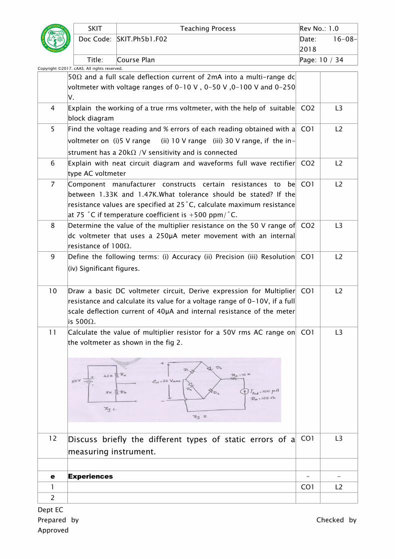
11 Calculate the value of multiplier resistor for a 50V rms AC range onthe voltmeter as shown in the fig 2.
CO1 L3
12 Discuss briefly the different types of static errors of ameasuring instrument.
CO1 L3
e Experiences - -1 CO1 L22
Dept ECPrepared by Checked byApproved
SKIT Teaching Process Rev No.: 1.0Doc Code: SKIT.Ph5b1.F02 Date: 16-08-
Module – 2Title: Digital Voltmeter and Digital Instruments Appr
Time:10 Hrs
a Course Outcomes - Blooms- The student should be able to: - Level1 Explain the functional concepts and functioning of DVM CO3 L22 Explain the working of AC and Dc signal Gauge instrument and apply
in laboratoryCO4 L3
b Course Schedule - -Class
NoModule Content Covered CO Level
10 Introduction, RAMP technique CO3 L211 Dual Slope Integrating Type DVM, Integrating Type DVM CO3 L312 Most Commonly used principles of ADC, Successive Approximations CO3 L313 3 1/2Digit, Resolution and Sensitivity of Digital Meters CO3 L214 General Specifications of DVM CO3 L215 Introduction, Digital Multimeters CO4 L216 Digital Frequency Meter, Digital Measurement of Time CO4 L317 Digital Frequency Meter, Digital Measurement of Time CO4 L318 Universal Counter, Digital Tachometer, Digital pH Meter CO4 L319 Digital Phase Meter, Digital Capacitance Meter CO4 L3
c Application Areas CO Level1 Measurement of pressure, temperature, flow or level in a chemical
process plantCO3 L3
2 Aid in electrochemical measurements for a variety of applicationsincluding food, agriculture, wastewater treatment, industrialprocesses,
CO4 L3
d Review Questions - -13 With block diagram explain the principle and operation of successive
approximation type DVM. CO3 L2
14 With schematic explain the principle and operation of digital fre-quency meter.
CO4 L2
15 Differentiate analog meters and digital meters CO3 L2
Dept ECPrepared by Checked byApproved
SKIT Teaching Process Rev No.: 1.0Doc Code: SKIT.Ph5b1.F02 Date: 16-08-
16 A 4 digit voltmeter is used for voltage measurements:
i) Find its resolution ii)How would 12.98 V displayed on a 10 v range? iii)How would 0.6973 V displayed on 1 V and 10 v ranges
CO3 L3
17 Explain the ramp type digital voltmeter with the help of block diagram CO4 L218 Explain the digital multimeter with basic circuit diagram. CO3 L219 With the help of block diagram explain the working of dual slope
DVM/ V-T type DVM.CO3 L2
20 A 4 digit voltmeter has an accuracy of ± 0.5% of reading ±1 digit.
(i) What is the possible error, in volts when the instrument isreading 5 V on 200 V range.
(ii) What is the possible error, in volts when the instrument isreading 0.1 V on 2 V range?
CO3 L3
21 Determine the resolution of a 3 digit display on 1V and 10V
ranges.
CO3 L3
22 Explain the working principle of V-F type DVM. CO3 L223 What is 3 digit DVM? Define its sensitivity. CO3 L2
24 List the advantages of digital instruments over analog instruments CO3 L225 Suppose the converter can measure a maximum of 5V i.e, 5V
corresponds to the maximum count of 11111111, if the test voltageis Vin=1V. Show the steps take place in the table format in themeasurement for the successive approximation type Digital Voltmeter
CO3 L3
26 Discuss briefly the general specifications of a digital voltmeter CO3 L227 With a basic block diagram, explain the method used for digital
measurement of time period. CO4 L2
e Experiences - -1 CO1 L2234 CO3 L35
Dept ECPrepared by Checked byApproved
SKIT Teaching Process Rev No.: 1.0Doc Code: SKIT.Ph5b1.F02 Date: 16-08-
E1. CIA EXAM – 1a. Model Question Paper - 1CrsCode:
17EC32 Sem: 3 Marks: 30 Time: 75 minutes
Course: Electronic Instrumentation- - Note: Answer any 2 questions, each carry equal marks. Mark
sCO Level
1 a Explain the following with example: a. Gross errors b. systematicerrors c. random errors d.absolute errors and relative errors.Also mention how to eliminate or reduce these errors
8 CO1 L2
b Explain the working principle of multi-range voltmeter, with help ofsuitable circuit diagram and also write relevant expressions.
7 CO2 L3
2 a Explain with neat circuit diagram and waveforms full wave rectifiertype AC voltmeter
7 CO2 L2
b Explain the following terms: (i) Accuracy (ii) Precision (iii) Resolution(iv) Significant figures.
8 CO1 L2
3 a With block diagram explain the principle and operation of successiveapproximation type DVM.
8 CO3 L2
b With schematic explain the principle and operation of digital fre-quency meter.
7 CO4 L2
4 a A 4 digit voltmeter is used for voltage measurements:
i) Find its resolution ii)How would 12.98 V displayed on a 10 v range? iii)How would 0.6973 V displayed on 1 V and 10 v ranges
7 CO3 L3
b Explain the ramp type digital voltmeter with the help of blockdiagram
8 CO4 L2
b. Assignment -1Note: A distinct assignment to be assigned to each student.
Model Assignment QuestionsCrs Code: 17EC32 Sem: 3 Marks: 10 Time: 90 – 120 minutesCourse: Electronic InstrumentationNote: Each student to answer 2-3 assignments. Each assignment carries equal mark.
Dept ECPrepared by Checked byApproved
SKIT Teaching Process Rev No.: 1.0Doc Code: SKIT.Ph5b1.F02 Date: 16-08-
1 1KT17EC001 Explain the working principle of multi-range voltmeter,with help of suitable circuit diagram and also write relev-ant expressions.
5 CO2 L3
2 1KT17EC002 Convert a basic D’Arsonval movement with an internalresistance of 50Ω and a full scale deflection current of2mA into a multi-range dc voltmeter with voltage rangesof 0-10 V , 0-50 V ,0-100 V and 0-250 V.
5 CO2 L2
3 1KT17EC003 Explain the working of a true rms voltmeter, with the helpof suitable block diagram
5 CO2 L3
4 1KT17EC004 Find the voltage reading and % errors of each reading ob-tained with a voltmeter on (i)5 V range (ii) 10 V range(iii) 30 V range, if the instrument has a 20kΩ /V sensitiv-ity and is connected
5 CO1 L2
5 1KT17EC005 Explain with neat circuit diagram and waveforms full waverectifier type AC voltmeter
5 CO2 L2
6 1KT17EC006 Determine the resolution of a 3 digit display on 1V and
10V ranges.
5 CO3 L3
7 1KT17EC007 Explain the working principle of V-F type DVM. 5 CO3 L28 1KT17EC008 What is 3 digit DVM? Define its sensitivity. 5 CO3 L2
9 1KT17EC009 List the advantages of digital instruments over analoginstruments
5 CO3 L2
10 1KT17EC010 Suppose the converter can measure a maximum of 5V i.e,5V corresponds to the maximum count of 11111111, ifthe test voltage is Vin=1V. Show the steps take place inthe table format in the measurement for the successiveapproximation type Digital Voltmeter
5 CO3 L3
11 1KT17EC011 Discuss briefly the general specifications of a digitalvoltmeter
5 CO3 L2
12 1KT17EC012 With a basic block diagram, explain the method used fordigital measurement of time period.
5 CO4 L2
13 1KT17EC013 Component manufacturer constructs certain resistances tobe between 1.33K and 1.47K.What tolerance should bestated? If the resistance values are specified at 25˚C,calculate maximum resistance at 75 ˚C if temperaturecoefficient is +500 ppm/˚C.
5 CO1 L2
14 1KT17EC014 Determine the value of the multiplier resistance on the 50V range of dc voltmeter that uses a 250µA meter
5 CO2 L3
Dept ECPrepared by Checked byApproved
SKIT Teaching Process Rev No.: 1.0Doc Code: SKIT.Ph5b1.F02 Date: 16-08-
movement with an internal resistance of 100Ω.15 1KT17EC015 Define the following terms: (i) Accuracy (ii) Precision (iii)
Resolution (iv) Significant figures.5 CO1 L2
16 1KT17EC016 Draw a basic DC voltmeter circuit, Derive expression forMultiplier resistance and calculate its value for a voltagerange of 0-10V, if a full scale deflection current of 40µAand internal resistance of the meter is 500Ω.
5 CO1 L2
17 1KT17EC017 Find the voltage reading and % errors of each reading ob-tained with a voltmeter on (i)5 V range (ii) 10 V range(iii) 30 V range, if the instrument has a 20kΩ /V sensitiv-ity and is connected
5 CO1 L2
18 1KT17EC018 Explain with neat circuit diagram and waveforms full waverectifier type AC voltmeter
5 CO2 L2
19 1KT17EC020 Determine the resolution of a 3 digit display on 1V and
10V ranges.
5 CO3 L3
20 1KT17EC021 Explain the working principle of V-F type DVM. 5 CO3 L221 1KT17EC022 What is 3 digit DVM? Define its sensitivity. 5 CO3 L2
22 1KT17EC023 List the advantages of digital instruments over analoginstruments
5 CO3 L2
23 1KT17EC024 Suppose the converter can measure a maximum of 5V i.e,5V corresponds to the maximum count of 11111111, ifthe test voltage is Vin=1V. Show the steps take place inthe table format in the measurement for the successiveapproximation type Digital Voltmeter
5 CO3 L3
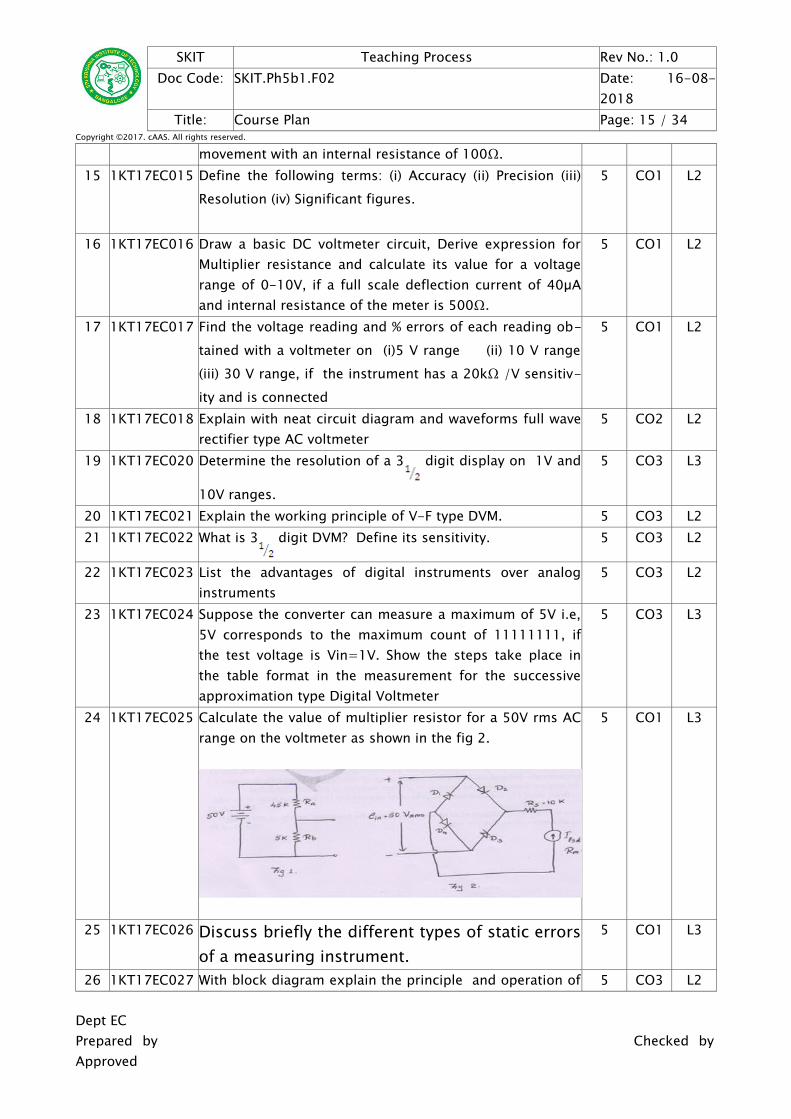
24 1KT17EC025 Calculate the value of multiplier resistor for a 50V rms ACrange on the voltmeter as shown in the fig 2.
5 CO1 L3
25 1KT17EC026 Discuss briefly the different types of static errorsof a measuring instrument.
5 CO1 L3
26 1KT17EC027 With block diagram explain the principle and operation of 5 CO3 L2
Dept ECPrepared by Checked byApproved
SKIT Teaching Process Rev No.: 1.0Doc Code: SKIT.Ph5b1.F02 Date: 16-08-
successive approximation type DVM. 27 1KT17EC028 With schematic explain the principle and operation of di-
gital frequency meter.5 CO4 L2
28 1KT17EC029 Differentiate analog meters and digital meters 5 CO3 L229 1KT17EC030 A 4 digit voltmeter is used for voltage measurements:
i) Find its resolution ii)How would 12.98 V displayed on a 10 vrange? iii)How would 0.6973 V displayed on 1 V and10 v ranges
5 CO3 L3
30 1KT17EC031 Explain the ramp type digital voltmeter with the help ofblock diagram
5 CO4 L2
31 1KT17EC032 Explain the digital multimeter with basic circuit diagram. 5 CO3 L232 1KT17EC033 With the help of block diagram explain the working of
dual slope DVM/ V-T type DVM.5 CO3 L2
33 1KT17EC035 Explain the working of a true rms voltmeter, with the helpof suitable block diagram
5 CO2 L3
34 1KT17EC036 Find the voltage reading and % errors of each reading ob-tained with a voltmeter on (i)5 V range (ii) 10 V range(iii) 30 V range, if the instrument has a 20kΩ /V sensitiv-ity and is connected
5 CO1 L2
35 1KT17EC037 Explain with neat circuit diagram and waveforms full waverectifier type AC voltmeter
5 CO2 L2
36 1KT17EC038 Determine the resolution of a 3 digit display on 1V and
10V ranges.
5 CO3 L3
37 1KT17EC040 Explain the working principle of V-F type DVM. 5 CO3 L238 1KT17EC041 What is 3 digit DVM? Define its sensitivity. 5 CO3 L2
39 1KT17EC042 List the advantages of digital instruments over analoginstruments
5 CO3 L2
40 1KT17EC043 Suppose the converter can measure a maximum of 5V i.e,5V corresponds to the maximum count of 11111111, ifthe test voltage is Vin=1V. Show the steps take place inthe table format in the measurement for the successiveapproximation type Digital Voltmeter
5 CO3 L3
41 1KT17EC044 Discuss briefly the general specifications of a digitalvoltmeter
5 CO3 L2
42 1KT17EC046 With a basic block diagram, explain the method used fordigital measurement of time period.
5 CO4 L2
43 1KT17EC047 Component manufacturer constructs certain resistances to 5 CO1 L2Dept ECPrepared by Checked byApproved
SKIT Teaching Process Rev No.: 1.0Doc Code: SKIT.Ph5b1.F02 Date: 16-08-
be between 1.33K and 1.47K.What tolerance should bestated? If the resistance values are specified at 25˚C,calculate maximum resistance at 75 ˚C if temperaturecoefficient is +500 ppm/˚C.
44 1KT17EC048 Determine the value of the multiplier resistance on the 50V range of dc voltmeter that uses a 250µA metermovement with an internal resistance of 100Ω.
5 CO2 L3
45 1KT16EC002 Define the following terms: (i) Accuracy (ii) Precision (iii)Resolution (iv) Significant figures.
5 CO1 L2
46 1KT16EC007 Draw a basic DC voltmeter circuit, Derive expression forMultiplier resistance and calculate its value for a voltagerange of 0-10V, if a full scale deflection current of 40µAand internal resistance of the meter is 500Ω.
5 CO1 L2
47 1KT16EC040 Find the voltage reading and % errors of each reading ob-tained with a voltmeter on (i)5 V range (ii) 10 V range(iii) 30 V range, if the instrument has a 20kΩ /V sensitiv-ity and is connected
5 CO1 L2
48 Diploma Explain with neat circuit diagram and waveforms full waverectifier type AC voltmeter
5 CO2 L2
D2. TEACHING PLAN - 2Module – 3
Title: Oscilloscope and Signal Generators ApprTime:
16 Hrs
a Course Outcomes - Blooms- The student should be able to: - Level1 Analyze the working of the oscilloscope and visualize the signal for
the parameter measurementCO5 L3
2 Generate waveforms with specified specification to apply to thecircuit
22 Simple CRO, Vertical Amplifier, Horizontal Deflecting System CO5 L323 Sweep or Time Base Generator, Measurement of Frequency by
Lissajous MethodCO5 L3
24 Measurement of Frequency by Lissajous Method CO5 L325 Digital Storage Oscilloscope CO5 L326 Introduction, Fixed and Variable AF Oscillator CO6 L327 Standard Signal Generator, Laboratory Type Signal Generator CO6 L328 AF sine and Square Wave Generator, Function Generator CO6 L3
c Application Areas CO Level1 Oscilloscopes are used to test CD/DVD and disk drive designs by
measuring disk performance, media noise and optical recordingcharacteristics.
CO5 L3
2 generally used in designing, testing, troubleshooting, and repairingelectronic or electroacoustic devices
CO6 L3
d Review Questions - -28 Write typical CRT connection details and explain different control
knobs on the front panel of the CRO. CO5 L2
29 What is the difference between dual beam and dual trace CRO? CO5 L230 An electrically deflected CRT has a final anode voltage of 2000 V and
parallel deflecting plates 1.5 cm long and 5 mm apart. If the screen is50 cm from the center of deflecting plates, find
(i) Beam speed (ii) The deflection sensitivity of the tube and(iii) The deflection factor of the tube.
CO5 L3
31 Draw the basic block diagram of an oscilloscope. Explain the functionof each block and mention the advantages of negative HV supply.
CO5 L2
32 Describe the following modes of operation available in a dual traceoscilloscope (i)ALTERNATE mode (ii) CHOP mode
CO5 L2
33 Explain the operation of an electronic switch, with the help of a basicblock diagram and circuit diagram
CO5 L2
34 Explain the CRT features briefly CO5 L235 With the basic block diagram, explain the principle of operation of
simple CROCO5 L2
36 Explain the working of dual trace CRO with neat block diagram. CO5 L337 Compare alternate sweep with chopped sweep CO5 L238 Explain sweep or time base generator with neat circuit diagram and
waveforms for a continuous sweep CRO and triggered sweep CRO. CO5 L2
39 Write a note on following controls available on CRO panel (i) Time base (ii) X-shift (iii) Y-shift
CO5 L2
Dept ECPrepared by Checked byApproved
SKIT Teaching Process Rev No.: 1.0Doc Code: SKIT.Ph5b1.F02 Date: 16-08-
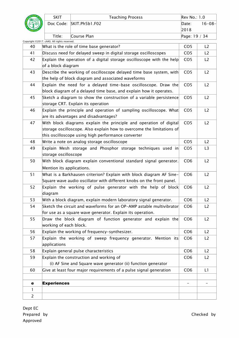
40 What is the role of time base generator? CO5 L241 Discuss need for delayed sweep in digital storage oscilloscopes CO5 L242 Explain the operation of a digital storage oscilloscope with the help
of a block diagramCO5 L2
43 Describe the working of oscilloscope delayed time base system, withthe help of block diagram and associated waveforms
CO5 L2
44 Explain the need for a delayed time-base oscilloscope. Draw theblock diagram of a delayed time base, and explain how it operates.
CO5 L2
45 Sketch a diagram to show the construction of a variable persistencestorage CRT. Explain its operation
CO5 L2
46 Explain the principle and operation of sampling oscilloscope. Whatare its advantages and disadvantages?
CO5 L2
47 With block diagrams explain the principle and operation of digitalstorage oscilloscope. Also explain how to overcome the limitations ofthis oscilloscope using high performance converter
CO5 L2
48 Write a note on analog storage oscilloscope CO5 L249 Explain Mesh storage and Phosphor storage techniques used in
storage oscilloscopeCO5 L3
50 With block diagram explain conventional standard signal generator.Mention its applications.
CO6 L2
51 What is a Barkhausen criterion? Explain with block diagram AF Sine-Square wave audio oscillator with different knobs on the front panel.
CO6 L2
52 Explain the working of pulse generator with the help of blockdiagram
CO6 L2
53 With a block diagram, explain modern laboratory signal generator. CO6 L254 Sketch the circuit and waveforms for an OP-AMP astable multivibrator
for use as a square wave generator. Explain its operation.CO6 L2
55 Draw the block diagram of function generator and explain theworking of each block.
CO6 L2
56 Explain the working of frequency-synthesizer. CO6 L257 Explain the working of sweep frequency generator. Mention its
applicationsCO6 L2
58 Explain general pulse characteristics CO6 L259 Explain the construction and working of
(i) AF Sine and Square wave generator (ii) function generatorCO6 L2
60 Give at least four major requirements of a pulse signal generation CO6 L1
e Experiences - -12
Dept ECPrepared by Checked byApproved
SKIT Teaching Process Rev No.: 1.0Doc Code: SKIT.Ph5b1.F02 Date: 16-08-
Module – 4Title: Measuring Instruments and bridges Appr
Time:16 Hrs
a Course Outcomes - Blooms- The student should be able to: - Level1 Measure the analog signal in the circuit CO7 L32 Apply the RLC bridge balancing in the circuit and measure frequency CO8 L4
b Course Schedule
ClassNo
Module Content Covered CO Level
29 Measuring Instruments: Field Strength Meter CO7 L330 Stroboscope, Phase Meter CO7 L331 Q Meter CO7 L332 Q Meter CO7 L333 Megger CO7 L334 Bridges: Introduction, Wheatstone‘s bridge CO8 L335 Kelvin‘s Bridge CO8 L336 AC bridges, Capacitance Comparison Bridge, CO8 L337 Inductance Comparison Bridge, Maxwell‘s bridge CO8 L338 Wien‘s bridge CO8 L3
c Application Areas CO Level1 Used in medical imaging systems CO7 L32 The applications of pressure transducer mainly involve in altitude
sensingCO8 L3
d Review Questions - -61 What are the limitations of Wheatstone’s bridge? Derive the balance
equation of Kelvin's Double Bridge for unknown low resistance. CO8 L2
62 Four arms of an AC bridge are as follows: AB = a pure capacitance of0.2 µF, BC = 500 Ω pure resistance, CD = unknown series circuitimpedance, DA = 0.1 µF capacitance in parallel with 300 Ωresistance. Arm BD is connected with a detector and 5 V, 1000 Hzsupply is connected across AC. Find unknown components valuewhich are in series in branch CD at bridge balance condition. Write
CO8 L3
Dept ECPrepared by Checked byApproved
SKIT Teaching Process Rev No.: 1.0Doc Code: SKIT.Ph5b1.F02 Date: 16-08-
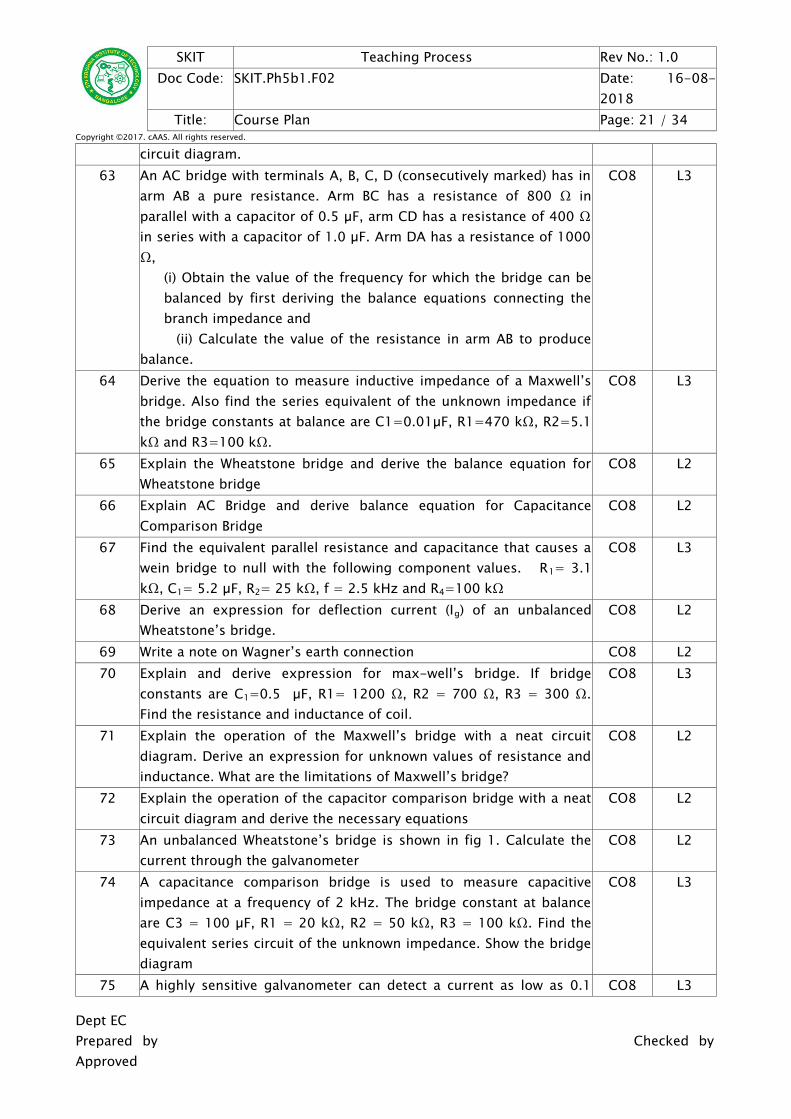
circuit diagram.63 An AC bridge with terminals A, B, C, D (consecutively marked) has in
arm AB a pure resistance. Arm BC has a resistance of 800 Ω inparallel with a capacitor of 0.5 µF, arm CD has a resistance of 400 Ωin series with a capacitor of 1.0 µF. Arm DA has a resistance of 1000Ω,
(i) Obtain the value of the frequency for which the bridge can bebalanced by first deriving the balance equations connecting thebranch impedance and
(ii) Calculate the value of the resistance in arm AB to producebalance.
CO8 L3
64 Derive the equation to measure inductive impedance of a Maxwell’sbridge. Also find the series equivalent of the unknown impedance ifthe bridge constants at balance are C1=0.01µF, R1=470 kΩ, R2=5.1kΩ and R3=100 kΩ.
CO8 L3
65 Explain the Wheatstone bridge and derive the balance equation forWheatstone bridge
CO8 L2
66 Explain AC Bridge and derive balance equation for CapacitanceComparison Bridge
CO8 L2
67 Find the equivalent parallel resistance and capacitance that causes awein bridge to null with the following component values. R1= 3.1kΩ, C1= 5.2 µF, R2= 25 kΩ, f = 2.5 kHz and R4=100 kΩ
CO8 L3
68 Derive an expression for deflection current (Ig) of an unbalancedWheatstone’s bridge.
CO8 L2
69 Write a note on Wagner’s earth connection CO8 L270 Explain and derive expression for max-well’s bridge. If bridge
constants are C1=0.5 µF, R1= 1200 Ω, R2 = 700 Ω, R3 = 300 Ω.Find the resistance and inductance of coil.
CO8 L3
71 Explain the operation of the Maxwell’s bridge with a neat circuitdiagram. Derive an expression for unknown values of resistance andinductance. What are the limitations of Maxwell’s bridge?
CO8 L2
72 Explain the operation of the capacitor comparison bridge with a neatcircuit diagram and derive the necessary equations
CO8 L2
73 An unbalanced Wheatstone’s bridge is shown in fig 1. Calculate thecurrent through the galvanometer
CO8 L2
74 A capacitance comparison bridge is used to measure capacitiveimpedance at a frequency of 2 kHz. The bridge constant at balanceare C3 = 100 µF, R1 = 20 kΩ, R2 = 50 kΩ, R3 = 100 kΩ. Find theequivalent series circuit of the unknown impedance. Show the bridgediagram
CO8 L3
75 A highly sensitive galvanometer can detect a current as low as 0.1 CO8 L3
Dept ECPrepared by Checked byApproved
SKIT Teaching Process Rev No.: 1.0Doc Code: SKIT.Ph5b1.F02 Date: 16-08-
nA. This galvanometer is highly used in a Wheatstone Bridge as adetector. Each arm of the bridge has a resistance of 1 kΩ. Theinput voltage applied to the bridge is 20 V. Calculate the smallestchange in resistance, which can be detected assuming the resistanceof the galvanometer is negligible.
76 Explain the operation of the Wien’s Bridge with a neat circuitdiagram. Derive the expression for the frequency. Mention thelimitations of this bridge
CO8 L2
77 A Wheatstone’s bridge is shown in fig 2 with correspondingresistances. The battery voltage is 5 V and its internal resistance isnegligible. The galvanometer used is of sensitivity 5 mm/µA and aninternal resistance of 200 Ω. Determine the deflection ofgalvanometer caused by 2 Ω unbalance in arm AD. Also determinethe sensitivity of the bridge in terms of deflection per unit change inresistance
CO8 L3
78 State the working principle of an output power meter CO7 L279 Explain with a diagram the working of an output power meter CO7 L380 How is field strength measured?Explain the basic principle of a field
strength meterCO7 L2
81 Explain the working of field strength meter using transistor CO7 L382 State the basic principles on which the stroboscope operates CO7 L283 Explain with a neat diagram the operation of a stroboscope CO7 L384 Explain how speed of a meter can be measured using the
stroboscopeCO7 L2
85 Explain with a neat diagram the working of a phase sensitive detector CO7 L386 Define Q factor and resonance.Explain the working principle of a Q
meterCO7 L2
87 Describe with a diagram the operation of a Q meter.List the factorsthat cause error in a Q meter
CO7 L3
88 Explain how Q meter can be used to measure the following i)Dcresistance of a coil ii)Stray Capacitance iii)impedance of a circuitiv)Characteristic impedance of a transmission line
CO7 L2
Dept ECPrepared by Checked byApproved
SKIT Teaching Process Rev No.: 1.0Doc Code: SKIT.Ph5b1.F02 Date: 16-08-
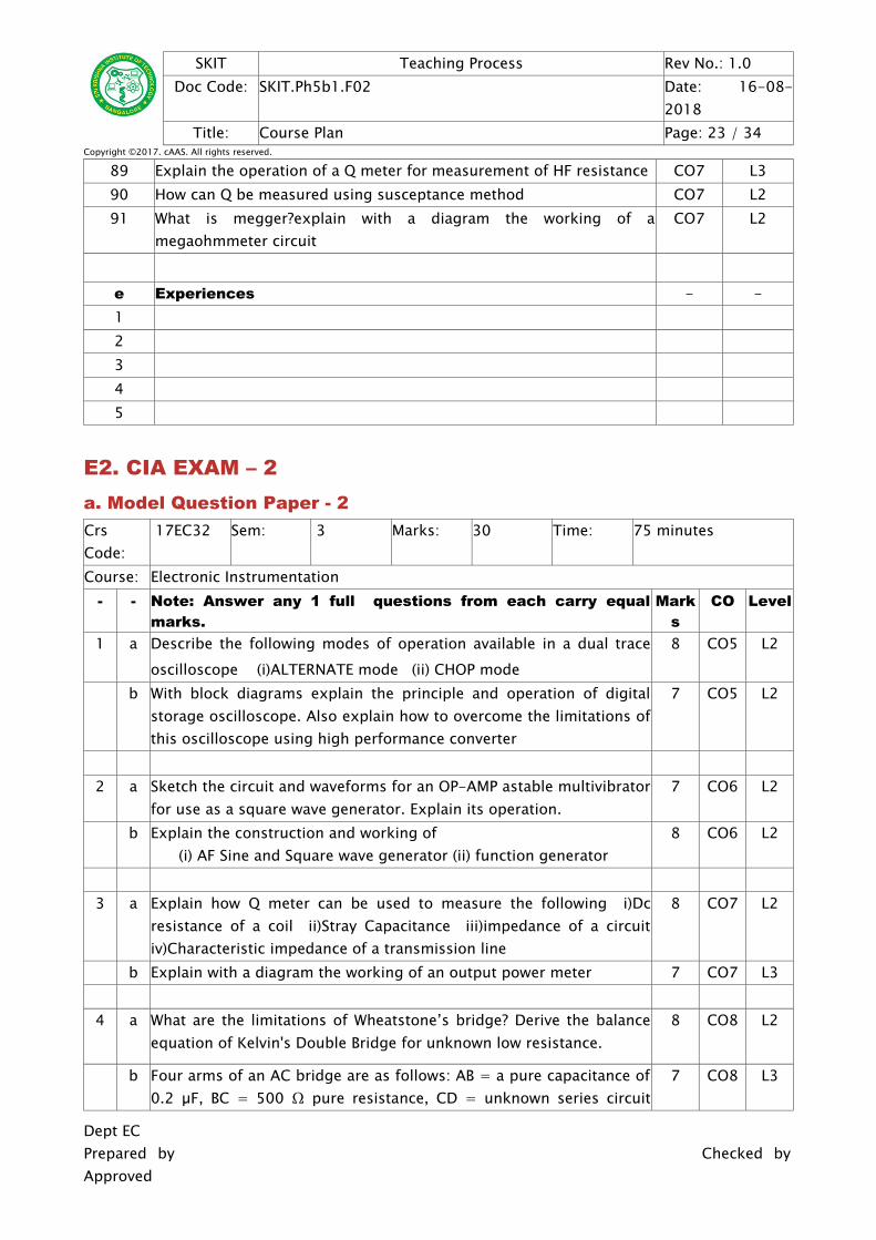
89 Explain the operation of a Q meter for measurement of HF resistance CO7 L390 How can Q be measured using susceptance method CO7 L291 What is megger?explain with a diagram the working of a
megaohmmeter circuitCO7 L2
e Experiences - -12345
E2. CIA EXAM – 2a. Model Question Paper - 2CrsCode:
17EC32 Sem: 3 Marks: 30 Time: 75 minutes
Course: Electronic Instrumentation- - Note: Answer any 1 full questions from each carry equal
marks.Mark
sCO Level
1 a Describe the following modes of operation available in a dual traceoscilloscope (i)ALTERNATE mode (ii) CHOP mode
8 CO5 L2
b With block diagrams explain the principle and operation of digitalstorage oscilloscope. Also explain how to overcome the limitations ofthis oscilloscope using high performance converter
7 CO5 L2
2 a Sketch the circuit and waveforms for an OP-AMP astable multivibratorfor use as a square wave generator. Explain its operation.
7 CO6 L2
b Explain the construction and working of (i) AF Sine and Square wave generator (ii) function generator
8 CO6 L2
3 a Explain how Q meter can be used to measure the following i)Dcresistance of a coil ii)Stray Capacitance iii)impedance of a circuitiv)Characteristic impedance of a transmission line
8 CO7 L2
b Explain with a diagram the working of an output power meter 7 CO7 L3
4 a What are the limitations of Wheatstone’s bridge? Derive the balanceequation of Kelvin's Double Bridge for unknown low resistance.
8 CO8 L2
b Four arms of an AC bridge are as follows: AB = a pure capacitance of0.2 µF, BC = 500 Ω pure resistance, CD = unknown series circuit
7 CO8 L3
Dept ECPrepared by Checked byApproved
SKIT Teaching Process Rev No.: 1.0Doc Code: SKIT.Ph5b1.F02 Date: 16-08-
impedance, DA = 0.1 µF capacitance in parallel with 300 Ωresistance. Arm BD is connected with a detector and 5 V, 1000 Hzsupply is connected across AC. Find unknown components valuewhich are in series in branch CD at bridge balance condition. Writecircuit diagram.
b. Assignment – 2Note: A distinct assignment to be assigned to each student.
Model Assignment QuestionsCrs Code: 17EC32 Sem: 3 Marks: 10 Time: 90 – 120 minutesCourse: Electronic InstrumentationNote: Each student to answer 2-3 assignments. Each assignment carries equal mark.SNo USN Assignment Description Mark
sCO Level
1 1KT17EC001 Explain the operation of a digital storage oscilloscope withthe help of a block diagram
5 CO5 L2
2 1KT17EC002 Describe the working of oscilloscope delayed time basesystem, with the help of block diagram and associatedwaveforms
5 CO5 L2
3 1KT17EC003 Explain the need for a delayed time-base oscilloscope.Draw the block diagram of a delayed time base, andexplain how it operates.
5 CO5 L2
4 1KT17EC004 Sketch a diagram to show the construction of a variablepersistence storage CRT. Explain its operation
5 CO5 L2
5 1KT17EC005 Explain the principle and operation of samplingoscilloscope. What are its advantages and disadvantages?
5 CO5 L2
6 1KT17EC006 With block diagrams explain the principle and operation ofdigital storage oscilloscope. Also explain how to overcomethe limitations of this oscilloscope using high performanceconverter
5 CO5 L2
7 1KT17EC007 Write a note on analog storage oscilloscope 5 CO5 L28 1KT17EC008 Explain Mesh storage and Phosphor storage techniques
used in storage oscilloscope5 CO5 L3
9 1KT17EC009 With block diagram explain conventional standard signalgenerator. Mention its applications.
5 CO6 L2
10 1KT17EC010 Explain the working of field strength meter usingtransistor
5 CO7 L3
11 1KT17EC011 State the basic principles on which the stroboscopeoperates
5 CO7 L2
Dept ECPrepared by Checked byApproved
SKIT Teaching Process Rev No.: 1.0Doc Code: SKIT.Ph5b1.F02 Date: 16-08-
12 1KT17EC012 Explain with a neat diagram the operation of astroboscope
5 CO7 L3
13 1KT17EC013 Explain how speed of a meter can be measured using thestroboscope
5 CO7 L2
14 1KT17EC014 Explain with a neat diagram the working of a phasesensitive detector
5 CO7 L3
15 1KT17EC015 Define Q factor and resonance.Explain the workingprinciple of a Q meter
5 CO7 L2
16 1KT17EC016 Describe with a diagram the operation of a Q meter.Listthe factors that cause error in a Q meter
5 CO7 L3
17 1KT17EC017 Explain how Q meter can be used to measure the followingi)Dc resistance of a coil ii)Stray Capacitance iii)impedanceof a circuit iv)Characteristic impedance of a transmissionline
5 CO7 L2
18 1KT17EC018 Explain the operation of a Q meter for measurement of HFresistance
5 CO7 L3
19 1KT17EC020 How can Q be measured using susceptance method 5 CO7 L220 1KT17EC021 What is megger?explain with a diagram the working of a
megaohmmeter circuit5 CO7 L2
21 1KT17EC022 Write typical CRT connection details and explain differentcontrol knobs on the front panel of the CRO.
5 CO5 L2
22 1KT17EC023 What is the difference between dual beam and dual traceCRO?
5 CO5 L2
23 1KT17EC024 An electrically deflected CRT has a final anode voltage of2000 V and parallel deflecting plates 1.5 cm long and 5mm apart. If the screen is 50 cm from the center ofdeflecting plates, find
(i) Beam speed (ii) The deflection sensitivity of thetube and (iii) The deflection factor of the tube.
5 CO5 L3
24 1KT17EC025 Draw the basic block diagram of an oscilloscope. Explainthe function of each block and mention the advantages ofnegative HV supply.
5 CO5 L2
25 1KT17EC026 Describe the following modes of operation available in adual trace oscilloscope (i)ALTERNATE mode (ii)CHOP mode
5 CO5 L2
26 1KT17EC027 Explain the operation of an electronic switch, with the helpof a basic block diagram and circuit diagram
5 CO5 L2
27 1KT17EC028 Explain the CRT features briefly 5 CO5 L228 1KT17EC029 With the basic block diagram, explain the principle of
operation of simple CRO5 CO5 L2
Dept ECPrepared by Checked byApproved
SKIT Teaching Process Rev No.: 1.0Doc Code: SKIT.Ph5b1.F02 Date: 16-08-
29 1KT17EC030 Explain the working of dual trace CRO with neat blockdiagram.
5 CO5 L3
30 1KT17EC031 Compare alternate sweep with chopped sweep 5 CO5 L231 1KT17EC032 Explain sweep or time base generator with neat circuit
diagram and waveforms for a continuous sweep CRO andtriggered sweep CRO.
5 CO5 L2
32 1KT17EC033 Write a note on following controls available on CRO panel (i) Time base (ii) X-shift (iii) Y-shift
5 CO5 L2
33 1KT17EC035 What is the role of time base generator? 5 CO5 L234 1KT17EC036 Discuss need for delayed sweep in digital storage
oscilloscopes5 CO5 L2
35 1KT17EC037 Explain the operation of a digital storage oscilloscope withthe help of a block diagram
5 CO5 L2
36 1KT17EC038 Describe the working of oscilloscope delayed time basesystem, with the help of block diagram and associatedwaveforms
5 CO5 L2
37 1KT17EC040 Explain the need for a delayed time-base oscilloscope.Draw the block diagram of a delayed time base, andexplain how it operates.
5 CO5 L2
38 1KT17EC041 Explain the working of pulse generator with the help ofblock diagram
5 CO6 L2
39 1KT17EC042 With a block diagram, explain modern laboratory signalgenerator.
5 CO6 L2
40 1KT17EC043 Sketch the circuit and waveforms for an OP-AMP astablemultivibrator for use as a square wave generator. Explainits operation.
5 CO6 L2
41 1KT17EC044 Draw the block diagram of function generator and explainthe working of each block.
5 CO6 L2
42 1KT17EC046 Four arms of an AC bridge are as follows: AB = a purecapacitance of 0.2 µF, BC = 500 Ω pure resistance, CD =unknown series circuit impedance, DA = 0.1 µFcapacitance in parallel with 300 Ω resistance. Arm BD isconnected with a detector and 5 V, 1000 Hz supply isconnected across AC. Find unknown components valuewhich are in series in branch CD at bridge balancecondition. Write circuit diagram.
5 CO8 L3
43 1KT17EC047 An AC bridge with terminals A, B, C, D (consecutivelymarked) has in arm AB a pure resistance. Arm BC has aresistance of 800 Ω in parallel with a capacitor of 0.5 µF,arm CD has a resistance of 400 Ω in series with acapacitor of 1.0 µF. Arm DA has a resistance of 1000 Ω,
5 CO8 L3
Dept ECPrepared by Checked byApproved
SKIT Teaching Process Rev No.: 1.0Doc Code: SKIT.Ph5b1.F02 Date: 16-08-
(i) Obtain the value of the frequency for which thebridge can be balanced by first deriving the balanceequations connecting the branch impedance and
(ii) Calculate the value of the resistance in arm AB toproduce balance.
44 1KT17EC048 Derive the equation to measure inductive impedance of aMaxwell’s bridge. Also find the series equivalent of theunknown impedance if the bridge constants at balance areC1=0.01µF, R1=470 kΩ, R2=5.1 kΩ and R3=100 kΩ.
5 CO8 L3
45 1KT16EC002 Explain the working of frequency-synthesizer. 5 CO6 L246 1KT16EC007 Explain the working of sweep frequency generator.
Mention its applications5 CO6 L2
47 1KT16EC040 Explain general pulse characteristics 5 CO6 L248 Diploma Derive the equation to measure inductive impedance of a
Maxwell’s bridge. Also find the series equivalent of theunknown impedance if the bridge constants at balance areC1=0.01µF, R1=470 kΩ, R2=5.1 kΩ and R3=100 kΩ.
5 CO8 L3
D3. TEACHING PLAN - 3Module – 5
Title: Transducers ApprTime:
16 Hrs
a Course Outcomes - Blooms- The student should be able to: - Level1 Explain the working of sensing devices CO9 L22 Describe the working of active and passive transducers CO10 L3
1 transducer is used to measure the temperature of the air such that tocontrol the temperature of several control systems like air-conditioning, heating, ventilation
CO9 L3
2 Sensors used in real time applications CO10 L3
d Review Questions - -92 What are the different types of photoelectric transducers? explain any
twoCO9 L2
93 Explain the principle of LED and RTD. Comment on theircharacteristics.
CO9 L3
94 Describe the working of optical pyrometer. Mention its merits anddemerits
CO9 L3
95 Write a neat sketch explain construction and working of platinumRTD.
CO9 L3
96 Explain important features of LCDs. CO9 L297 Explain how power is measured using a suitable bolometer bridge
diagram.CO9 L3
98 Write a short note on signal conditioning system CO9 L299 Explain piezo electrical transducer, with circuit diagram. Mention its
disadvantagesCO9 L3
100 Explain the light emitting diodes (LED) with diagram CO9 L3101 What is LED and LCD? Compare LED and LCD display devices. CO9 L2102 Write a note on photo transistor. CO10 L2103 List the classifications of digital displays CO10 L2104 Explain in brief effects of photo conductive and photovoltaic
transducer. CO10 L3
105 Write short notes on (i)RF power measurement using bolometer ii)Lab
view
CO10 L3
106 Define the terms (i)Seebeck effect (ii) Peltier effect CO10 L2107 Mention the advantages and limitations of RTD CO10 L3108 Write short notes on photo transistor CO10 L3
E3. CIA EXAM – 3a. Model Question Paper - 3CrsCode:
17EC32 Sem: 3 Marks: 30 Time: 75 minutes
Course: Electronic Instrumentation- - Note: Answer any 2 questions, each carry equal marks. Mark
sCO Level
1 a Explain the principle of LED and RTD. Comment on theircharacteristics.
7 CO9 L3
b Describe the working of optical pyrometer. Mention its merits anddemerits
8 CO9 L3
2 a Describe the principle of operation of pressure transducer employingeach of the following principles i)Resistive Transducers ii)Inductivetransducers iii)capacitive transducers
8 CO9 L3
b Explain how power is measured using a suitable bolometer bridgediagram.
7 CO9 L3
3 a Explain in brief effects of photo conductive and photovoltaictransducer.
8 CO10 L3
b Explain the Working principle of thermistors 7 CO10 L2
4 a Explain the working principle of thermocouple 7 L2b Write short notes on (i)RF power measurement using bolometer ii)Lab
view
8 CO10 L3
b. Assignment – 3Note: A distinct assignment to be assigned to each student.
Model Assignment QuestionsCrs Code: 17EC32 Sem: 3 Marks: 10 Time: 90 – 120 minutesCourse: Electronic InstrumentationNote: Each student to answer 2-3 assignments. Each assignment carries equal mark.SNo USN Assignment Description Mark
sCO Level
1 1KT17EC001 Explain the light emitting diodes (LED) with diagram 5 CO9 L32 1KT17EC002 What is LED and LCD? Compare LED and LCD display
devices. 5 CO9 L2
3 1KT17EC003 Write a note on photo transistor. 5 CO10 L24 1KT17EC004 List the classifications of digital displays 5 CO10 L2
Dept ECPrepared by Checked byApproved
SKIT Teaching Process Rev No.: 1.0Doc Code: SKIT.Ph5b1.F02 Date: 16-08-
5 1KT17EC005 Explain in brief effects of photo conductive andphotovoltaic transducer.
5 CO10 L3
6 1KT17EC006 Write short notes on (i)RF power measurement using bolo-
meter ii)Lab view
5 CO10 L3
7 1KT17EC007 Define the terms (i)Seebeck effect (ii) Peltier effect 5 CO10 L28 1KT17EC008 Mention the advantages and limitations of RTD 5 CO10 L39 1KT17EC009 Write short notes on photo transistor 5 CO10 L310 1KT17EC010 What are the different types of photoelectric transducers?
explain any two5 CO9 L2
11 1KT17EC011 Explain the principle of LED and RTD. Comment on theircharacteristics.
5 CO9 L3
12 1KT17EC012 Describe the working of optical pyrometer. Mention itsmerits and demerits
5 CO9 L3
13 1KT17EC013 Write a neat sketch explain construction and working ofplatinum RTD.
5 CO9 L3
14 1KT17EC014 Explain important features of LCDs. 5 CO9 L215 1KT17EC015 Explain important features of LCDs. 5 CO9 L216 1KT17EC016 Explain how power is measured using a suitable bolometer
bridge diagram.5 CO9 L3
17 1KT17EC017 Write a short note on signal conditioning system 5 CO9 L218 1KT17EC018 Explain piezo electrical transducer, with circuit diagram.
Mention its disadvantages5 CO9 L3
19 1KT17EC020 Explain the light emitting diodes (LED) with diagram 5 CO9 L320 1KT17EC021 What is LED and LCD? Compare LED and LCD display
devices. 5 CO9 L2
21 1KT17EC022 Write a note on photo transistor. 5 CO10 L222 1KT17EC023 List the classifications of digital displays 5 CO10 L223 1KT17EC024 Define the terms (i)Seebeck effect (ii) Peltier effect 5 CO10 L224 1KT17EC025 Mention the advantages and limitations of RTD 5 CO10 L325 1KT17EC026 Write short notes on photo transistor 5 CO10 L326 1KT17EC027 What are the different types of photoelectric transducers?
explain any two5 CO9 L2
27 1KT17EC028 Explain the principle of LED and RTD. Comment on theircharacteristics.
5 CO9 L3
28 1KT17EC029 Describe the working of optical pyrometer. Mention itsmerits and demerits
5 CO9 L3
29 1KT17EC030 Write a neat sketch explain construction and working ofplatinum RTD.
5 CO9 L3
30 1KT17EC031 Explain important features of LCDs. 5 CO9 L231 1KT17EC032 Explain important features of LCDs. 5 CO9 L2
Dept ECPrepared by Checked byApproved
SKIT Teaching Process Rev No.: 1.0Doc Code: SKIT.Ph5b1.F02 Date: 16-08-
32 1KT17EC033 Explain how power is measured using a suitable bolometerbridge diagram.
5 CO9 L3
33 1KT17EC035 Write a short note on signal conditioning system 5 CO9 L234 1KT17EC036 Explain piezo electrical transducer, with circuit diagram.
Mention its disadvantages5 CO9 L3
35 1KT17EC037 Explain the light emitting diodes (LED) with diagram 5 CO9 L336 1KT17EC038 What is LED and LCD? Compare LED and LCD display
devices. 5 CO9 L2
37 1KT17EC040 Write a note on photo transistor. 5 CO10 L238 1KT17EC041 List the classifications of digital displays 5 CO10 L239 1KT17EC042 Explain the light emitting diodes (LED) with diagram 5 CO9 L340 1KT17EC043 What is LED and LCD? Compare LED and LCD display
devices. 5 CO9 L2
41 1KT17EC044 Write a note on photo transistor. 5 CO10 L242 1KT17EC046 List the classifications of digital displays 5 CO10 L243 1KT17EC047 Explain in brief effects of photo conductive and
photovoltaic transducer. 5 CO10 L3
44 1KT17EC048 Write short notes on (i)RF power measurement using bolo-
meter ii)Lab view
5 CO10 L3
45 1KT16EC002 Define the terms (i)Seebeck effect (ii) Peltier effect 5 CO10 L246 1KT16EC007 Mention the advantages and limitations of RTD 5 CO10 L347 1KT16EC040 Write short notes on photo transistor 5 CO10 L348 Diploma Write a note on photo transistor. 5 CO10 L2
1. University Model Question PaperCourse: Electronic Instrumentation Month / Year May /2018Crs Code: 17EC32 Sem: 3 Marks: 100 Time: 180
minutes- Note Answer all FIVE full questions. All questions carry equal marks. Mark
sCO Leve
l1
New Scheme-Model Question paper not yet Available
-
Dept ECPrepared by Checked byApproved
SKIT Teaching Process Rev No.: 1.0Doc Code: SKIT.Ph5b1.F02 Date: 16-08-
2 Draw the block diagram of a true RMS voltmeter and explain itsoperation
5 CO2 2018
3 Sketch and explain the operation of a multirange ammeter usingAryton shun
8 CO2
4 What is the loading effect of a voltmeter of low sensitivity? A voltageof 100 V dc is applied across a series combination of two resistors R1and R2 each of 10 Ka A voltmeter to of sensitivity 1 is used tomeasure the voltage across R2 in the range of 50 V.Calculate thevoltmeter reading and percentage error of reading
CO2 2018
5 The expected value of the voltage across a resistor is 80 V. Howeverthe measurement gives a value of 79 V calculate (i) absolute error (ii)% error (iii) Relative accuracy (iv) % of accuracy.
4 CO1 2017
2 1 Describe with diagram, the operation of a successive approximationtype DVM.
8 CO4 2018
2 i)With the help of a block diagram, explain the operation of a digitalcapacitance meter. (ii) What are the outstanding characteristics of aDVM
8 CO3 2018
3 Calculate the value of multiplier resistance on the 50V range of a dcvoltmeter that uses a 500pA meter movement with aninternal.resistance 1K ohm
4 CO3 2018
4 Explain with diagram the operation of true RMS voltmeter. 8 CO3 20175 Explain with diagram the operation of a dc differential voltmeter 8 CO3 2017
3 1 Draw the block diagram of a simple CRO and state the functions ofeach block. What is the advantage of using —ve HV supply in CRO?
8 CO5 2018
2 i)Describe the operation of a digital storage oscilloscope with thehelp of a block diagram. (ii) The number of vertical and horizontaltangencies of a Lissajous figure are 2 and 6 respectively. What is thefrequency of the signal connected to vertical plates, if horizontalplate signal frequency is 1 kHz.
8 CO5 2018
Dept ECPrepared by Checked byApproved
SKIT Teaching Process Rev No.: 1.0Doc Code: SKIT.Ph5b1.F02 Date: 16-08-
3 sketch the block diagram of a square and pulse generator anddescribe how it generates the square waveform and pulses.
8 CO6 2018
4 Describe with the help of neat block diagram the operation ofmodern laboratory signal generator. Explain the technique used toimprove stability.
8 CO6 2017
5 Sketch the block diagram and explain the AF sine and square wavegenerator. List the various controls on the front panel of AF sine andsquare wave generation
8 CO6 2017
4 1 Define Q factor. With diagram, explain the operation of a Q meter tomeasure Q and inductance of a coil.
8 CO7 2018
2 Draw the diagram of a Maxwell's Bridge and obtain the equations tomeasure Rx, 1_, and Q.
5 CO8 2018
3 Derive the balance equation for wheat stone bridge and mention thelimitation
6 CO8 2017
4 What is Meggar? Explain basic Meggar circuit 8 CO7 20185 Draw the circuit diagram and obtain balance condition for Maxwell's
bridge, if bridge constants are C1 = 0.5 .tF, RI = 1200 0, R2 = 700SI, R3 = 300 n, find resistance and inductance of the coil.
8 CO8 2017
6 Explain with a diagram the operation of stroboscope 8 CO7 20175 1 i)Explain with diagram the construction of a Bonded Resistance wire
gauge. How does it senses strain/stress? (ii) How it is used in abridge arrangement with a dummy gauge and what is the advantagesof such an arrangement?
8 CO9 2018
2 With circuit diagram, explain the operation of a LVDT the method ofmeasuring displacement.
6 CO10 2018
3 Describe with diagram the operation of a piezo electric transducer. 5 CO9 20184 What is a thermistor? Explain different types of thermisters. 8 CO10 20175 List the factors to be considered while selecting transducers. 8 CO9 2017


![Uciderea lui Roger Ackroyd [1.0].doc](https://static.documents.pub/doc/80x56/56d6be7b1a28ab30169250e7/uciderea-lui-roger-ackroyd-10doc.jpg)


