SkyRAN: A Self-Organizing LTE RAN in the SkyAyon Chakraborty Eugene Chai Karthikeyan Sundaresan Amir Khojastepour
Sampath RangarajanNEC Laboratories America, Inc.
ABSTRACTWe envision a flexible, dynamic airborne LTE infrastructure builtupon Unmanned Autonomous Vehicles (UAVs) that will provideon-demand, on-time, network access, anywhere. In this paper, we de-sign, implement and evaluate SkyRAN, a self-organizing UAV-basedLTE RAN (Radio Access Network) that is a key component of thisUAV LTE infrastructure network. SkyRAN determines the UAV’soperating position in 3D airspace so as to optimize connectivityto all the UEs on the ground. It realizes this by overcoming vari-ous challenges in constructing and maintaining radio environmentmaps to UEs that guide the UAV’s position in real-time. SkyRAN isdesigned to be scalable in that it can be quickly deployed to provideefficient connectivity even over a larger area. It is adaptive in thatit reacts to changes in the terrain and UE mobility, to maximizeLTE coverage performance while minimizing operating overhead.We implement SkyRAN on a DJI Matrice 600 Pro drone and evalu-ate it over a 90 000m2 operating area. Our testbed results indicatethat SkyRAN can place the UAV in the optimal location with about30 secs of a measurement flight. On an average, SkyRAN achieves athroughput of 0.9 – 0.95× of optimal, which is about 1.5 – 2× overother popular baseline schemes.
KEYWORDSLTE, RAN, UAV, 5G, Localization, Radio Environment Map, TacticalCommunications
1 INTRODUCTIONWe envision an autonomous, cellular network built upon unteth-ered, low-altitude Unmanned Aerial Vehicles (UAVs) that are rapidlydeployable to provide uninterrupted, on-demand LTE network access,anywhere. This UAV network can be flown into desired regions andbe deployed either in conjunction with existing fixed infrastructureto augment capacity and coverage (e.g., surge in traffic demands,stadiums, concerts) or independently into remote or challengingenvironments, such as rural locations, mountainous terrains or dis-aster areas, to provide temporary connectivity in areas that willotherwise be unreachable by fixed infrastructure. The operationalendurance of each such LTE node is heavily dependent on theUAV platform. This endurance can range from several minutes to
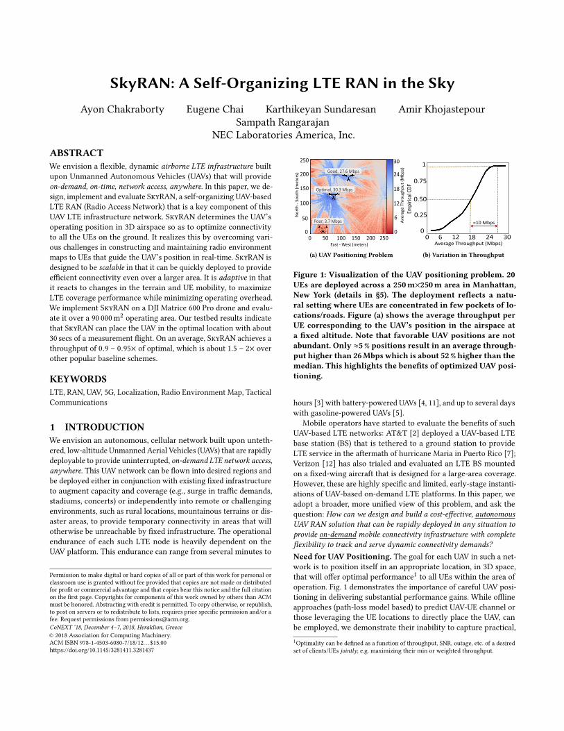
Figure 1: Visualization of the UAV positioning problem. 20UEs are deployed across a 250m×250m area in Manhattan,New York (details in §5). The deployment reflects a natu-ral setting where UEs are concentrated in few pockets of lo-cations/roads. Figure (a) shows the average throughput perUE corresponding to the UAV’s position in the airspace ata fixed altitude. Note that favorable UAV positions are notabundant. Only ≈5% positions result in an average through-put higher than 26Mbps which is about 52% higher than themedian. This highlights the benefits of optimized UAV posi-tioning.
hours [3] with battery-powered UAVs [4, 11], and up to several dayswith gasoline-powered UAVs [5].
Mobile operators have started to evaluate the benefits of suchUAV-based LTE networks: AT&T [2] deployed a UAV-based LTEbase station (BS) that is tethered to a ground station to provideLTE service in the aftermath of hurricane Maria in Puerto Rico [7];Verizon [12] has also trialed and evaluated an LTE BS mountedon a fixed-wing aircraft that is designed for a large-area coverage.However, these are highly specific and limited, early-stage instanti-ations of UAV-based on-demand LTE platforms. In this paper, weadopt a broader, more unified view of this problem, and ask thequestion: How can we design and build a cost-effective, autonomousUAV RAN solution that can be rapidly deployed in any situation toprovide on-demand mobile connectivity infrastructure with completeflexibility to track and serve dynamic connectivity demands?Need for UAV Positioning. The goal for each UAV in such a net-work is to position itself in an appropriate location, in 3D space,that will offer optimal performance1 to all UEs within the area ofoperation. Fig. 1 demonstrates the importance of careful UAV posi-tioning in delivering substantial performance gains. While offlineapproaches (path-loss model based) to predict UAV-UE channel orthose leveraging the UE locations to directly place the UAV, canbe employed, we demonstrate their inability to capture practical,1Optimality can be defined as a function of throughput, SNR, outage, etc. of a desiredset of clients/UEs jointly; e.g. maximizing their min or weighted throughput.
CoNEXT ’18, December 4–7, 2018, Heraklion, Greece Ayon Chakraborty et al.
heterogeneous terrains, as well as adapt to UE dynamics in §2.2.Hence, realizing this objective in practice requires the UAV to probeand profile the radio channel between itself (at a multitude of lo-cations in 3D air-space) and every UE location on the ground (i.e.construct a UE-specific RF map) in real-time, before solving a jointoptimization objective across all UEs to determine its optimal po-sition. Solutions today largely focus on the optimization problem,while assuming that all the required RF information is known andUEs being static (or their locations known) [15, 26]. Indeed, thebigger challenge facing practical deployment of these networks,lies in the accurate estimation of real-time information (RF maps)critical to determining the optimal UAV position even in the faceof UE dynamics. This in turn forms the focus of this work.
Challenges. The finer the granularity of the air-space from whichthe RF channel is probed (longer probing duration/overhead), thegreater is the accuracy of the estimated RF maps and the resultingoptimality of the UAV position. However, the UAV’s motion duringprobing can cause the path loss (Tx-Rx power in dB) to the UEs tovary rapidly and significantly (over 20 dB in our experiments, Fig. 7),resulting in a highly sub-optimal connectivity for the UEs. Hence,it is critical for the UAV to minimize its probing overhead (timein motion) and maximize the time spent in delivering optimizedcoverage to its UEs from a stationary position. Tackling this tradeoffrequires us to carefully address three key challenges:(1) Scalable Radio Environment Map (REM) Estimation. The largerthe coverage area (O (N 2), N being points in 1D) of the ground ter-rain, the larger is the corresponding airspace (O (N 3)) to be probed.Further, the higher the complexity of the terrain (buildings, foliage,etc.), the higher the heterogeneity (variations and features) in theREM (i.e. RF map). Extrapolating simple path loss models is nolonger sufficient to capture such heterogeneity, and requires a finergranularity of probing (large number of UAV probing positions) inthe 3D space, adding to more overhead.(2) Adapting to UE Dynamics. Note that REMs are estimated withrespect to specific UE locations. Hence, appreciable UE mobility cancontribute to changes in their REM and in turn to the optimal UAVposition. However, frequent repositioning of the UAV to cater toindividual UE mobility would incur significant overhead and mightnot be practical. On the other hand, being overly conservative aboutrepositioning the UAV might lead to degraded performance. Thus,it is important to strike a balance between frequent UAV positionupdates and deteriorated connectivity.(3) UE Location-awareness. Given that a REM corresponds to a fixedUE location on ground, knowledge about the UE location will fa-cilitate reuse of previously gathered data or estimated REM (e.g.,for a UE that moves to a location or neighborhood, where REMis already available). The lack of UE location information at theUAV, leaves little room for balancing the tradeoff between probingoverhead and estimation accuracy. Our experiments show that aUE localization error of about 10m or more can have a significantimpact on UAV positioning and hence system performance (§2.4,fig. 9). Existing UE localization algorithms [16, 28, 34, 36] that aredesigned for static BSs (macro-cells) deliver localization accuraciesin the order of several tens to hundred meters. This is not sufficient,especially for small cells that cater to 1 Km2 area or less. Further,
the noisy measurements resulting from the UAV’s mobility makesit challenging to obtain the desired localization accuracy.
SkyRAN.Towards addressing these challenges, we present SkyRAN–a first-of-its-kind system that automates and optimizes the entireprocess of UAV-driven LTE RAN deployments, namely REM con-struction and UAV placement. SkyRAN adopts ameasurement-basedapproach to construct and maintain REMs: it leverages channel datacollected from measurement flights for UE localization and an REMestimation algorithm that is both scalable to large coverage areasand adaptive to UE dynamics. Briefly, SkyRAN’s operation involvesthree key design elements (seen in Fig. 2):(1) UAV-Optimized UE Localization. SkyRAN leverages the mo-bility of the UAV to create a synthetic aperture array, and the syn-chronous nature of LTE transmissions to range the UE organically(using just LTE) from this array (multiple locations) and eventuallylocalize it. At the start of an epoch, it executes a short random flighttrajectory during which it records LTE’s PHY-layer Synchroniza-tion Reference Signals (SRS) to each UE. From the latter, it infersthe respective signal time-of-flight (ToF) and hence range to eachUE. Such signals being LTE standards compliant, are supportedon all LTE UE devices. To derive the UE’s location, the UAV’s GPSand ToF data are then used in a multilateration algorithm that isrobust to measurement inaccuracies arising from terrain obstaclesand UAV mobility.(2) Spatial Filtering for Scalability.Armedwith the UE locations,SkyRAN then computes and executes an intelligent flight trajectoryfor probing all the UEs simultaneously. The trajectory is computedby identifying unexplored regions in the airspace with high signalgradients (variations) and evaluating their contribution to increasedREM accuracies for the UEs against the added cost to probe them.This allows SkyRAN to prioritize its probing overhead for spatialregions that have a larger impact on the estimation of REM. Thisprovides scalability to larger areas of operation than would beotherwise possible with exhaustive measurement approaches. TheRF data from probing is then interpolated to obtain an REM for eachUE, which is finally used to determine the UAV’s optimal position.(3) Temporal Aggregation for Adaptability. Instead of reactingto individual UE mobility, SkyRAN triggers a new epoch only whenwhen collective UE dynamics (mobility of multiple UEs) impacts theaggregate system performance (by a configuredmargin). Thereupon,it executes its probing step to refine and update its REMs as needed.Further, REMs constructed for locations in prior epochs are reusedwhen UEs visit these locations or their neighborhood in future.Using such prior information, SkyRAN is able to adapt and optimizeits probing flight trajectory to further minimize overhead even inthe face of UE dynamics.
We realize SkyRAN with a custom designed payload consistingof two Small Board Computers (SBCs), one to execute the softwareEPC and the other to run an OpenAirInterface eNodeB, a USRPB210 and an LTE antenna, a LTE power amplifier and duplexer. Thepayload is mounted on a DJI M600Pro drone, which serves as ourUAV. Our onboard custom flight control software, built on top ofthe DJI OnBoard SDK, enables SkyRAN to operate autonomouslyon the drone.
In our real-world flight experiments, given a fixed overhead(distance flown), SkyRAN reconstructs an REM of within 2 dB of
SkyRAN: A Self-Organizing LTE RAN in the Sky CoNEXT ’18, December 4–7, 2018, Heraklion, Greece
N
N
NREMs
K Informative Points, K << N2
Operating 3D Airspace, O(N3)
2D REM
Incremental Updates# Measurements << K
SCALABILITY
Ope
ratin
g Al
titud
e
Measurement Trajectoryfor 2D REM (N2)
2D REM
2D Terrain O(N2)
2D REM, O(N2)
ADAPTIBILITY
Figure 2: Probing the 3D space to obtain best operating point.SkyRAN chooses an optimal height for the UAV to operatein and constructs an optimal measurement trajectory in the2D plane to estimate theREMs for a set of UE locations. SuchREMs are stored and historical data is used in case UEs reap-pear in similar locations where REMs have been estimatedpriorly.the optimal, which helps SkyRAN optimize the UAV’s position. Onan average, SkyRAN achieves a throughput of 0.9 – 0.95× of optimal,which is about 2× that of a baseline scheme employing a uniformsearch trajectory for probing, and about 1.5× over non-REM basedapproaches that employ just the UE locations.
A demo of SkyRAN is available at http://www.nec-labs.com/skyran. We also supplement our evaluation with large-scale trace-driven simulations that capture more UEs, heterogeneous terrains,UE dynamics, etc. by employing real-world LIDAR datasets foraccurate terrain construction.
2 BACKGROUND AND MOTIVATIONIn this section, we discuss the deployment of the UAV-based LTEnetwork along with the challenges and design principles chosen toaddress them.
2.1 Deployment ModelWe envision a holistic UAV LTE infrastructure network consist-ing of UAV RANs that can either operate independently of otherfixed networks, deployed in hard-to-reach terrain that is outsidethe range of existing fixed infrastructure, or used as hotspots toaugment the capacity of fixed networks for targeted areas such assports stadiums, concert halls, parades or in response to local, highattendance events.
Each SkyRAN UAV accomplishes this task of autonomous cover-age operation using its three components (as shown in Fig. 13): (a)an LTE Evolved Node B (eNodeB), which directly connects to UEson the ground; (b) an Evolved Packet Core (EPC) that provides LTEcore functionality (i.e. UE authentication and registration, routing,RAN state management etc) to the UEs in the UAV’s area of opera-tions; and (c) a flight control core that provides autonomous flightcapability, and runs all of the SkyRAN algorithms.
The focus of our work is the design, implementation and evaluationof a single SkyRAN UAV in this UAV LTE network. Our design isinherently scalable and can be extended to operate in a multi-UAVscenario, as briefly discussed in §8.
Figure 4: Estimated RF maperror w.r.t. ground truthfrom a exhaustive UAVprobing flights over fourdifferent terrains.
0 200 400 600 800 1000East - West (meters)
0
200
400
600
800
1000
Nor
th -
Sou
th (m
eter
s)
80 90 100 110 120 130 140 150
LTE
Pat
hlos
s (d
B)
UE
Figure 5: Different flighttrajectories overlaid on aground-truth RF map.
0
5
10
15
20
25
0 10 20 30 40 50
Med
ian
RE
M A
ccur
acy
(dB
)
Apprx. Fraction Of Terrain Probed (%)
Location Aware ProbingNaive Probing
Figure 6: RF map error de-creases as increasing propor-tion of the area of operationsis probed.
2.2 A Measurement-Based ApproachA measurement-based approach is necessary for a SkyRAN UAV tocapture an accurate picture of the radio-frequency characteristics.Without measurements, the UAV can only choose an operating po-sition either randomly, or with respect to the UE locations. While,random UAV positioning offers no guarantee on performance, aUAV positioning that is based solely on UE locations can also behighly sub-optimal. As an example, Fig. 3 shows a real-world RFmap with the average RF signal strength to all three UEs from everypoint in the operating area. This RF map is obtained from a UAV fly-ing in an exhaustive measurement trajectory over the testing area.A UAV operating at the centroid of these three UEs will achieve≈ 30 – 50% lower throughput (see Fig. 21 in §4.5 for further details)than a UAV at the optimal position derived from the RF map mea-surement. The degradation is more pronounced in complex terrains(i.e. with more natural or man-made obstructions), highlighting thelimitations of a geographical approach (based on UE locations) toUAV positioning. Hence, there is a need to characterize the radioenvironment through a measurement-based approach.
2.3 Use of Radio Environment MapsSkyRAN adopts a measurement-based approach to REM construc-tion, which in turn determines the optimal operating position ofthe UAV. It can be argued that there are simpler alternatives toradio environment maps (REMs): one can either construct the REMusing a free-space path-loss model without measurements, or use athroughput map instead of a REM. When compared to throughputmaps, REMs offer a lower-level, higher fidelity view of the actual
CoNEXT ’18, December 4–7, 2018, Heraklion, Greece Ayon Chakraborty et al.
70
75
80
85
90
95
100
0 10 20 30 40 50
LTE
Pat
hlos
s (d
B)
Segment Of UAV’s Flight Trajectory (m)
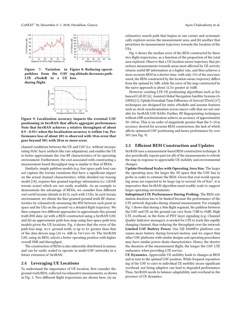
Figure 7: Variation inpathloss from the UAVLTE eNodeB to a UEduring flight.
Figure 9: Localization accuracy impacts the eventual UAVpositioning in SkyRAN that affects aggregate performance.Note that SkyRAN achieves a relative throughput of about0.9 – 0.95×when the localization accuracy is within 5m. Per-formance loss of about 10% is observed with 10m error thatgoes beyond 50% with 20m or more error.
channel conditions between the UE and UAV (i.e. without incorpo-rating MAC-layer artifacts like rate adaptation), and enables the UEto better approximate the true RF characteristics of its operatingenvironment. Furthermore, the cost associated with constructing ameasurement-based throughput map is similar to that of REMs.
Similarly, simple pathloss models (e.g. free space path loss) can-not capture the terrain variations that have a significant impacton the actual channel characteristics, while detailed ray-tracingmodel [18], requires fine-grained topology information (i.e. LiDARterrain scans) which are not easily available. As an example todemonstrate the advantage of REMs, we consider four differentreal-world terrains (details in §3.5), each with 3 UEs. In each terrainenvironment, we obtain the fine-grained ground truth RF charac-teristics by exhaustively measuring the RSS between each point inspace and the UEs on the ground via a detailed flight trajectory. Wethen compare two different approaches to approximate this groundtruth RSS data: (a) with a REM constructed using a SkyRAN UAV,and (b) an approximate path-loss map using free-space path-lossmodels given the UE locations. Fig. 4 shows that the error of thepath-loss map, w.r.t. ground truth, is up to 4× greater than thatof the data-driven map (10 vs. 4dB in Terrain-4). The SkyRANUAV, using its REM, selects a better operating position with higheroverall SNR and throughput.
The construction of REMs is also inherently distributed in nature,and can be easily scaled to operate in multi-UAV networks in afuture extension of SkyRAN.
2.4 Leveraging UE LocationsTo understand the importance of UE location, first consider theground-truth REM, collected via exhaustivemeasurements, as shownin Fig. 5. Two different flight trajectories are shown here, (a) an
exhaustive search path that begins at one corner and systemati-cally explores across the measurement area, and (b) another thatprioritizes its measurement trajectory towards the location of theUEs.
Fig. 6 shows the median error of the REM constructed by thesetwo flight trajectories, as a function of the proportion of the totalarea explored. Observe that a UE location-aware trajectory that pri-oritizes measurements towards areas most affected by UE activityreturns useful RF information at a higher rate, and thus achieves amore accurate REM in a shorter time: with only 15% of the area mea-sured, the REM constructed by the location-aware trajectory differsfrom the optimal by 5dB, while the error of the map constructed bythe naive approach is about 12.5× greater at 16dB.
However, existing LTE UE positioning algorithms such as En-hanced Cell-ID [6], Assisted Global Navigation Satellite Systems (A-GNSS) [1], Uplink/Downlink TimeDifference of Arrival (TDoA) [17]techniques are designed for static eNodeBs and assume featuressuch as clock-synchronization across macro cells that are not suit-able for SkyRAN UAV RANs. Further, RF fingerprinting techniqueswithout eNB synchronization achieve an accuracy of approximately50–100m. This is an order of magnitude greater than the 5–10maccuracy desired for accurate REM construction, the lack of whichaffects optimized UAV positioning and hence performance by over50% (see Fig. 9).
2.5 Efficient REM Construction and UpdatesSkyRAN uses a measurement-based REM construction technique. Italso periodically repeats part (or all) of the measurements to refreshthe map in response to appreciable UE mobility and environmentalchanges.Update Overhead Scales with Operating Area Size. The largerthe operating area, the larger the 3D space that the UAV has toprobe in order to estimate the REM. Given that real-world operat-ing areas are expected to be large (up to several 10s of Km2, it isimperative that SkyRAN algorithm must readily scale to supportlarger operating environments.Suboptimal LTE Performance During Probing. The REM esti-mation duration has to be limited because the performance of theLTE network degrades during channel measurement. For example,Fig. 7 shows that during a 50m flight segment, the pathloss betweenthe UAV and UE on the ground can vary from 77dB to 95dB. HighLTE overhead, in the form of PHY layer signaling (e.g. ChannelQuality Indicator messages), is needed for LTE to track this rapidlychanging channel, thus reducing the throughput over the network.Limited UAV Battery Power. Our DJI M600Pro platform con-sumes more battery during forward motion, and we expect thatother UAV platforms with similar designs and operating proceduresmay have similar power-drain characteristics. Hence, the shorterthe duration of the measurement flight, the longer the UAV LTEendurance when providing LTE service.UE Dynamics. Appreciable UE mobility leads to changes in REMand in turn to the optimal UAV position. While frequent reposition-ing of the UAV to cater to individual UE mobility incurs significantoverhead, not being adaptive can lead to degraded performance.Thus, SkyRAN needs to balance adaptability and overhead in thepresence of UE dynamics.
SkyRAN: A Self-Organizing LTE RAN in the Sky CoNEXT ’18, December 4–7, 2018, Heraklion, Greece
3 SKYRAN: DESIGNSkyRAN is designed for scalable and adaptable UAV RAN operation.In this section, we give an overview of the design and operationalprocedures of SkyRAN, followed by a description of the algorithmsemployed.
3.1 SkyRAN OverviewEpoch-basedOperation. SkyRANoperation followsmultiple timeepochs. Fig. 10 illustrates the operation of a SkyRAN UAV in a singletime epoch, as it is providing LTE coverage to an area.SkyRAN Operation. The SkyRAN UAV is launched with theboundaries of the operation area as its sole parameter. In eachtime epoch, the UAV first undertakes a UE localization flight,which is a short random flight trajectory within the operation area.This flight is used to collect LTE SRS data from the UEs so thattheir location can be determined by the SkyRAN UAV. Once theUE positions are found, the SkyRAN UAV computes and executesan optimal measurement flight trajectory to estimate the REM.The SkyRANUAV then computes the optimal position from thisREM, and positions itself at this position to provide LTE service.This position is retained until a new epoch is dynamically triggeredin response to appreciable UE dynamics (discussed in Section §3.5),upon which, the sequence of operations in Fig. 10 is repeated.
3.2 UE LocalizationSkyRAN uses UE location information to plan flight trajectories thatmaximize the accuracy of the REMs. UE locations allow SkyRAN tocoordinate measurement flights across large areas to best cover theUEs at known positions (scalability), and monitor UEs for mobilityto guide update and future measurement flights to keep the REMsupdated (adaptability). It is thus a key feature in SkyRAN.Localization Overview. SkyRAN uses multilateration in principleto determine the location of each UE in the operating area. We notethat all of these UEs are associated with the LTE eNodeB on theSkyRAN UAV.
Steps 1–4 of Fig. 10 illustrates the process of UE localization. TheSkyRAN UAV moves along a short, random flight trajectory andrecords the GPS positions of the UAV (Step 1) and the uplink LTESynchronization Reference Signals (SRS) (Step 2) from each UE.The SkyRAN UAV computes the time-of-flight (ToF) of the signalfrom the UE to the eNodeB using these SRS data (Step 3). The ToFand UAV GPS data is then used by the multilateration algorithm todetermine the UE location.
3.2.1 RawData Collection (Steps 1 and 2). UAVGPSPosition.TheGPS positions of the UAV are sampled at 50Hz during the UAV flight.Each position reading is timestamped using the global system clock,so that it can be time-aligned with the SRS data.LTESRSData.The uplink Synchronization Reference Signal (SRS) [9]is a known PHY-layer signal sent from the UE and received at theeNodeB, and is used by the eNodeB to measure the state of the up-link LTE channel from the UE. This signal occupies an LTE OFDMsymbol withN subcarriers, which we refer to as the SRS symbol. TheSkyRAN UAV receives uplink frequency-domain SRS symbols fromeach UE once every 10ms (or 100Hz). Each report is timestampedby the eNodeB using same system clock.
3.2.2 ToF Computation (Step 3). LTE subframes are transmittedin a time-deterministic manner. Hence, the time-of-flight of theRF signal from the UE to the eNodeB can be inferred from thedelay between the time the SRS symbol is transmitted by the UE, tothe time it is received at the eNodeB. The UE transmission time issynchronized with the eNodeB, and thus is known at the SkyRANUAV.
A received SRS symbol with its N OFDM sample values can beexpressed as s = [s (1) , . . . , s (N )]. Let the known SRS symbol trans-mitted by the UE be represented similarly as h = [h(1) , . . . ,h(N )].Note that s and h are frequency-domain values. Using the cross-correlation property of the Discrete Fourier Transform (DFT), wecan find the delay of the SRS symbol from the magnitude peak ofthe sequence
where ⊙ is the element-wise multiplication operator, ifft(·) isthe inverse fast fourier transform function, and (·)∗ is the complexconjugate function.
However, (1) only gives the delay to the nearest time-domainsample offset, which has a low resolution. For example, for a 10MHzLTE band (that is actually sampled at 15.36MHz), each sampledifference corresponds to a real-world distance of 19.5m. In orderto get a higher delay measurement resolution, we upsample bothsi and h: to get a delay resolution to within 1/K of a sample, weupsample the SRS sequence by K times. Since si is a frequencydomain SRS symbol, this upsampling process is accomplished byzero-padding the sequence:
where 0(1) , . . . , 0(N (K−1)) is a sequence of N (K − 1) zeros insertedinto the middle of the SRS symbol si . The transmitted SRS symbol his upsampled in the same manner to obtain h. Let y = ifft(si ⊙ h∗)as in (1), then the delay offset of the received SRS symbol is
t =1Kmaxpos(y) =
1Kmaxpos([|y (1) |, . . . , |y (N ) |]) (3)
where maxpos(·) returns the index of the element in sequence ywiththe largest absolute value, and | · | is the magnitude operator. Notethat the larger the value of K , the lower the SNR of the peak of thecorrelation2. This limits the practical accuracy of this upsamplingmethod for large K . In our implementation, we select K = 4 tostrike a good balance and yields good ToF accuracy.
Due to the higher SRS reporting rate, there are multiple ToF val-ues, t (1)i , . . . , t
(M )i , between any two consecutive UAV GPS reports
дi and дi+1. We average these M ToF values ti = (PMk=0 t
(k )i )/M
and assign the mean value ti to UAV GPS report дi to generate astream of GPS-ToF tuples (дi , ti ) at the same UAV GPS reportingrate of 50Hz. This continuous sequence of GPS-ToF tuples are thenused in the multilateration algorithm to resolve the position of theUE.
2The magnitude of the inverse FFT is scaled by 1/(KN ) while the noise is unchanged
CoNEXT ’18, December 4–7, 2018, Heraklion, Greece Ayon Chakraborty et al.
���������������
������������������������
������������
������������
����������������������
����������������
� �
�
������������
������������������
���������������������
����������
������������
�������
�����������
� �
�
�����������������
����������� ����������� �����������
Figure 10: Overview of the SkyRAN UAV RAN operation when providing LTE service.
3.2.3 UE Localization (Step 4). The ToF can be mapped to physicaldistance via multiplication by the propagation distance of the RFsignal per sample time. However, ToF processing onboard the UAVincurs a constant processing delay, which manifests as a constantToF/distance offset that must be eliminated. SkyRAN compensatesfor this offset by directly incorporating it as an unknown in theequation for ranging distance between the UE and the UAV. Sucha series of equations (from different UAV positions) can then besolved for the UE’s location by re-casting it into a least-squaresformulation (for better robustness to noisy UAV measurements),and adopting a gradient descent based iterative solution. In theinterest of space, we omit the mathematical details behind theoffset incorporated multi-lateration formulation.
3.3 Estimating Radio Environment MapsAfter the UEs have been localized, SkyRAN estimates the RadioEnvironment Maps (REMs) for the UEs in its coverage area, anduses them to estimate the optimal placement of the UAV in the3D airspace. However the sheer scale of measurement overheadrequired, assuming a brute-force approach, to sample the entire3D airspace is prohibitive. Also such REMs need to be createdacross UEs. SkyRAN intelligently prunes the airspace to filter outinformative points to conduct measurements in, that enriches theREMs with minimal overhead.
Steps 5–7 of Fig. 10 shows the three key steps involved in theREM estimation: SkyRAN first determines the optimal operatingaltitude (Step 5). It then finds the REM measurement trajectory (Step6), and uses the data collected over that trajectory to update theREMs (Step 7) for individual UEs. Finally, SkyRAN estimates theoptimal UAV position and moves to provide LTE service at thatposition.
Quantizing Space. The UAV GPS coordinates in SkyRAN are ob-served to have an accuracy of 1m–5m. SkyRAN thus quantizes itsoperating area into 1m×1m grid cells.
3.3.1 Finding Optimal Altitude (Step 5). A comprehensive RF chan-nel profile requires a REM at every altitude to each UE. Notwith-standing its excessive overhead, REM at different altitudes tend toreveal dependent RF information capturing the underlying terraincharacteristics. Hence, SkyRAN strikes a balance between overheadand accurate REM construction – it identifies a target operatingaltitude, for which it constructs an accurate REM.
It finds this target altitude using a key insight related to RF pathloss: there exists an optimal altitude where UAV-to-UE path loss isminimized. Increasing the altitude further results in increased pathloss (greater distance) whereas decreasing the altitude magnifies
the impact of shadowing effects due terrain obstacles (e.g., buildingsand trees) increasing path loss. This effect is shown in Fig. 8 thatreports UAV-to-UE path loss as a function of the UAV’s altitude. Wenote that while [14] presents an analytical way of determining theoptimal altitude of the UAV for maximizing coverage, it requiresdetailed terrain information unavailable in a practical setup likeSkyRAN.SkyRAN’s Approach: In the first epoch, the SkyRAN UAV posi-tions itself directly above the centroid of the locations of the activeUEs at an altitude of 120m (the maximum allowable altitude underFAA regulations). Next the UAV starts decreasing its altitude whiletracking the decreasing path loss till the altitude with minimumpath loss is found. In all subsequent epochs, SkyRAN estimates therelevant REMs specific to that target altitude. Constructing REMsat this target altitude has shown to yield 0.9–0.95× of the optimalperformance in our experiments. Note that this target altitude is notupdated every epoch but only when appreciable network dynamicsis detected (discussed in §3.5).
3.3.2 Computing Flight Trajectory (Step 6). A flight trajectory isa path taken by the SkyRAN UAV through its operating area toobtain RF measurements that will feed into REM construction. Wequantize this path into points that are 1m apart. This quantizedpath is computed over the following four steps:Step 6.1: Aggregating REMs. A REM for a UE is a 2D grid of1m×1m cells in the airspace, covering the operating area of SkyRANUAV (at the target altitude). Each grid cell shows the signal-to-noiseratio (SNR) from that cell to the UE’s location. The aggregate REMis the end-result of a grid cell-wise sum of the per-UE REMs in thecurrent epoch. Fig. 11 illustrates this aggregation step.Step 6.2: Gradient Map (Spatial Filtering). SkyRAN computesthe SNR gradient map from the aggregate REM. The gradient ofeach grid cell is the greatest difference between its SNR and theSNR of its directly adjacent, neighboring cells. The gradient mapis thus a 2D map showing the SNR’s gradient of each cell withinthe operating area of the SkyRAN UAV. Cells with higher valuesof gradients denote areas of higher SNR fluctuations. The goal ofthe SkyRAN UAV is to bias its measurement efforts to such highgradient grid cells. This enables us to more accurately capture thefine grained variations in SNR (critical for eventual REM estimation),while limiting overhead even in large terrains.Step 6.3: Location Clusters. SkyRAN partitions the grid cells intohigh and low gradient cells. The cells with gradients greater thanthe median of the gradient map are the high-gradient cells, with theother cells considered low-gradient. Measurement efforts are onlyfocused on the high-gradient grid cells. In spite of this partition, it
SkyRAN: A Self-Organizing LTE RAN in the Sky CoNEXT ’18, December 4–7, 2018, Heraklion, Greece
is still infeasible for a SkyRAN UAV to visit each grid cell. SkyRANthus applies K-means clustering over the high-gradient cells tospatially group them into K clusters, each with its own clusterhead.Step 6.4: Trajectory and InformationGain. SkyRAN constructsa flight trajectory through theK cluster heads by solving a travelingsalesman problem with these K cluster heads as nodes to visit.The length of the trajectory and its spatial coverage depends onK . SkyRAN constructs paths for each K ∈ {Kmin , . . . ,Kmax } andselects the best trajectory, i.e. the path with the highest information-to-cost ratio.Trajectory Information. Each existing (i.e. non-new) UE is associ-ated with a set of flight trajectories from previous epochs. Notethat a new UE does not have any flight trajectory history, and isthus assigned an empty set. For each UE, each measurement flightobtains new information about state of the channel from itself toother points in the operating area. To quantify this information,we define the information gain that a new trajectory provides to aUE as the shortest distance between the new trajectory and all thehistorical trajectories in the set assigned to the UE. The informationgain for a new UE (i.e. with an empty trajectory set) is high. For thesake of mathematical tractability, we assigned a large fixed valueImax to it. The average information gain is the the mean informa-tion gains over all UEs in the current epoch. SkyRAN’s formulationfor information helps measurements in relatively unexplored areas.Information-to-Cost Ratio. The cost of a trajectory is its length. Theinformation-to-cost ratio is thus the ratio of the average informa-tion gain of the trajectory to its length. SkyRAN selects the newtrajectory with the highest information-to-cost ratio, thus max-imizing the value of measurement data collected over the flighttrajectory.
Estimated REMs Till epoch = (T-1)
Gradient Map For The Superimposed REMs
Cost2
UE 3
UE 2
UE 1
Gradient > Threshold
Gradient < Threshold
Info2
Cost3
Info3
Cost4
Info4*REM: Radio Environment Map
Spatial K-M
eans Clustering
Superimposed REM
s
K=2
K=3
K=4
Figure 11: Schematic of the SkyRAN trajectory constructionalgorithm.
3.3.3 Update REM (Step 7). Measurement Update. During themeasurement flight, the LTE eNodeB PHY reports the SNR to eachUE at 100Hz. The SkyRAN UAV also reads its GPS position (fromthe UAV flight controller) at 50Hz. For each per-UE REM, the SNRof the a grid cell along the flight trajectory is assigned the averageof all SNR readings taken within that grid cell.Interpolation. SkyRAN uses a relatively lightweight interpolationtechnique called Inverse Distance Weighting, IDW3 to estimate the3Although sophisticated and more computationally intensive interpolation techniqueslike Gaussian Process Regression or Ordinary Kriging have been used to interpolateradio maps but it has been shown to offer marginal improvement over IDW (see [30]).
SNRs at grid cells that are not directly on the measurement flighttrajectory. To estimate the value of SNR at a given cell, IDW usesthe weighted mean of the SNR values of its neighboring cells, wherethe weight is determined by square of the inverse distances betweenthe center of the cell and the center of its neighboring cells.
3.4 Estimate Optimal UAV PositionSkyRAN UAV positions itself at the grid call that satisifies the max-min SNR across all UEs to provide LTE service during the epoch.This choice of a max-min metric ensures a minimal QoS to all theUEs present in the SkyRAN’s network and is a common objective forcoverage problems. To achieve this, SkyRAN first constructs a min-SNR map, where each 1m×1m grid cell is assigned the minimumSNR values of the corresponding grid cells over all other per-UEREMs. The optimal UAV position is then selected as the min-SNRgrid cell with the maximum value. Note that SkyRAN is equallyapplicable to other performance objectives (e.g. weighted UE SNR)aswell. SkyRAN thenmoves itself to this optimal position to provideLTE service to the UEs until the next epoch, where the steps inFig. 10 are repeated all over.
3.5 Adapting to UE DynamicsDynamic epoch to balance overhead andperformance.Changesin UE locations due to mobility can affect their REM, thereby neces-sitating a reposition of the UAV for optimal connectivity. However,UAV repositioning requires a new epoch, where the UEs’ REMs arere-estimated by probing more locations along a computed flighttrajectory - an overhead that is prohibitive at a frequent scale. Theshorter the epoch duration (i.e. frequent epochs), the more respon-sive the UAV’s positioning can be to individual UE movements.However, this not only contributes to excessive probing overhead,but might also result in the UAV constantly adapting its positionwithout being able to deliver optimized connectivity from a givenposition. On the other hand, a longer epoch duration is not favorableeither as substantial UE mobility may result in significant changesto the network topology, thereby resulting in heavily degraded con-nectivity. Given that SkyRAN’s objective is to provide optimizedconnectivity to all the UEs jointly, it strikes a balance betweenoverhead and performance by dynamically triggering epochs thatrespond to aggregate UE dynamics. Specifically, a new epoch is trig-gered when the aggregate performance drops beyond a predefinedthreshold that can be set by the operator (say, 10%). Fig. 12 showsthe degradation of overall throughput performance as a function ofthe epoch duration. Initially, the UAV is positioned optimally butas time advances, a fraction of the UEs move along certain prede-fined routes (scripted to closely mimic human mobility) withoutany change to UAV position. It can be observed that even a smallthreshold (e.g. 10% loss) allows for a reasonable epoch duration(10 minutes), thereby allowing SkyRAN to balance overhead andadaptability.Temporal aggregation ofREMs forminimizing overhead. SkyRAN’sapproach of REM construction and update is designed to implicitlyoptimize overhead in the presence of UE dynamics. Note that aREM is constructed for the position of a UE, rather than for the UEitself, as the latter can move around. Thus, when a UE moves by alarge distance (over R) with respect to its current position, SkyRAN
CoNEXT ’18, December 4–7, 2018, Heraklion, Greece Ayon Chakraborty et al.
0
0.25
0.5
0.75
1
0 10 20 30 40 50 60
Rel
ativ
e Th
roug
hput
Time (mimutes)
25% UEs Move50% UEs Move75% UEs Move
Figure 12: Degradation of throughput performance withtime where the UAV does not reposition itself while a frac-tion the UEs move. The results give a ballpark on the lengthof an epoch, say 10 mins while the relative throughput iswithin 80% of optimal.
can initialize the UE, at its new position, with an existing REM thatis measured for a position within R of its latest position.This allowsSkyRAN to leverage REMs from prior epochs that are spatiallyrelevant for the UE. This contributes to efficient REM updates withminimal overhead even in the face of UE mobility.
Only when a UE has moved to a position, where no prior REMexists (within range R), SkyRAN initializes a new REM using afree-space path-loss (FSPL) model: each cell in the new REM willrepresent the SNR from the UAV to the UE, at its new position, aspredicted by the FSPL model, rather than through measurements.However, this new REM will be updated with measurement dataas they come in during successive epochs that are relevant to thegiven UE. The factor R is chosen depending on the scale and theterrain complexity of the coverage area. A higher value of R tradesoff REM’s accuracy for scalability. In our current setup, we choosea R of 10m from Fig. 9, as it provides minimal performance loss(<10%), while allowing for reduced overhead through REM reuse.
4 IMPLEMENTATION AND EVALUATION4.1 ImplementationWe implement SkyRAN with a custom-built LTE system mountedunder a DJI Matrice 600 Pro (M600Pro) drone. Fig. 13 shows apicture of our SkyRAN LTE UAV.Hardware. The SkyRAN drone is built using two single-boardcomputers (SBCs), one with a Intel Core i7 and the other with aJ1900 CPU. A USRP B210 with a GPS clock serves as the LTE RFfrontend. This is connected to a LTE duplexer, power amplifier (PA)and low-noise amplifier (LNA) that provides about 18dB gain onboth the LTE downlink and uplink channels. This is all connectedto a 5dBi LTE antenna. All the hardware is mounted to the droneusing a custom-built carbon fiber frame with dampers to minimizevibration transfer from the drone. The backhaul (command andcontrol) network in our current implementation uses the AT&TLTE network via a separate LTE phone tether. This design choice ismade for the sake of convenience as the backhaul design is outsidethe scope of our work. This LTE backhaul link can be replaced withother technologies such as mmWave, WiFi, or LTE-U etc.
OAI EPC
SkyRAN eNodeB
Omnidirectional Antenna
Figure 13: A snapshot of our SkyRAN LTE UAV in operationand an UE connected to its network.
Software.We use OpenAirInterface [10] eNodeB and EPC softwareon the SBCs. The i7 SBC executes the LTE eNodeB, flight controlsoftware and SkyRAN algorithms, and the J1900 SBC runs the LTEEPC. The flight control software is built using the DJI OnBoardSDK, and enables fully hands-free autonomous drone flight. Whenlaunched, the SkyRAN drone autonomously executes the localiza-tion, REM measurement and optimal placement without any directuser input (e.g. through the remote controller).
Operating Range.With the LTE PA and LNA, the SkyRAN LTEsystem has a real-world operating range of over 300m. This oper-ating range is achieved even when the UE is in a NLOS situation,with buildings and/or tall trees between the UE and the drone. Theflight time of the SkyRAN drone is up to 30 minutes. The maximumoperating altitude of the drone is 120m above ground level, as perFAA regulations.
SkyRAN Demonstration. A demonstration of the SkyRAN UAVin operation, providing LTE service within our test area can befound at http://www.nec-labs.com/skyran. This demonstration flightshows the SkyRAN UAV conducing the UE localization flight, fol-lowed by a measurement trajectory to estimate the the REM. TheSkyRAN UAV then moves to the position that provides optimizedLTE service for all UEs jointly.
4.2 Testbed OperationWe deploy and test SkyRAN in a 90 000m2 area (shown in Fig. 15)surrounding (and including) our campus building. Our performanceresults reported in this section are based on 35 SkyRAN test flightswithin this test area.Testbed Limitation: We evaluate SkyRAN in our testbed using onlystatic UEs. A larger scale performance study of SkyRAN over mul-tiple epochs, and larger, more varied environments is presented in§5.
Smartphone UEs.We deploy seven Moto G5 LTE smartphones asUEs that connect to the SkyRAN LTE network. The UE locationsare selected to ensure that all UEs experience both LOS and NLOSchannels to the UAV over the course of a measurement flight. TheUEs will thus experience highly varying channel conditions duringthe SkyRAN operation, as shown in Fig 14.
SkyRAN: A Self-Organizing LTE RAN in the Sky CoNEXT ’18, December 4–7, 2018, Heraklion, Greece
SNR SNR
Rela
tive
Freq
uenc
y
-20 15 50 -20 15 500
0.5
10
0.5
1 UE7UE1
UE6UE5
Figure 14: SNR distributionof selected UEs during thesame SkyRAN flight.
7
1
2
345
6
300 meters300 m
eters
LTE UE
UAV
Figure 15: Coverage area ofSkyRAN. The yellow trajec-tory shows the tracks takenby SkyRAN’s UAV to collectground truthmeasurements.
�������
��������
������������������
Figure 16: Trajectory of theUniform and Centroid af-ter theUE localizationflight.
0
0.2
0.4
0.6
0.8
1
0 5 10 15 20 25
Em
piric
al C
DF
Ranging Error (m)
UE 1
UE 6
UE 7
Figure 17: CDF showing dis-tribution of accuracy for ToFbased ranging for UEs 1,5 and7 for a 20m longflight trajec-tory.
Algorithms. In our testbed experiments, we compare the perfor-mance of SkyRAN with two other UAV placement algorithms: Uni-form and Centroid.
Uniform does not use UE location information and REMs, andinstead adopts a zigzag trajectory across the test area, starting fromone corner of the test area boundary, to measure the channel stateuniformly as shown in Fig. 16.
Centroid uses UE locations, but does not use REMs. Instead, itmoves directly to the centroid of the UE locations to provide UAVLTE service, and is illustrated in Fig. 16.Ground Truth Channel State. For a given set of UE positions(based on SkyRAN’s localization), we fly the SkyRAN in a zigzagmanner to collect detailed measurements from each UE to UAVpositions throughout the test area. Fig. 15 shows the trajectory ofthis ground-truth measurement flight. This allows us to constructa detailed ground-truth REM, and determine the true optimal UAVoperating point. We compare the UAV position obtained throughSkyRAN, centroid and uniform with this ground-truth location.While we do this at multiple altitudes, for easier exposition ofdifferent schemes, we present results for UAV positioning at a givenaltitude.
4.3 UE Localization AccuracyAs mentioned in §3, the measurement trajectory is preceded by ashort flight to localize the UEs. In the following section, we present
0
0.2
0.4
0.6
0.8
1
0 5 10 15 20 25
Em
piric
al C
DF
Localization Error (m)
UE 1
UE 6
UE 7
Figure 18: Distribution of lo-calization errors for UEs 1,6and 7 for a 20m long flight.
0
2
4
6
8
10
5 10 15 20 25 30Med
ian
Loca
lizat
ion
Err
or (m
)
Length of Flight Trajectory (m)
Figure 19: Median localiza-tion error as a function offlight trajectory budget.
the localization performance for UEs located in three different typesof environments: UE 1 is located in the parking lot region (openspace); UE 6 is right beside a large office building; and UE 7 is withina heavily forested portion of the test area, with 35m high trees.Ranging Accuracy. The ranging accuracy of course depends onaccurate estimation of the time of flight (ToF). Depending on theenvironment, the ToF could be very noisy (standard deviation ashigh as 25 ns). In LoS, however, ToF is less noisy (standard deviation≈5 ns) The median ranging error is about 4 – 5m over a 20m local-ization flight as shown in Fig 17, and this accuracy is not affected bythe UE location. This is achieved with an SRS upsampling of K = 4that improves the ranging accuracy with a minimal reduction inSNR. We consider an LTE bandwidth of 10MHz in our experiments.We have found, through further experiments, that this accuracyholds when UEs are randomly placed at other locations in the testarea.Localization Accuracy. Fig. 18 shows the CDF of the UE locationsdetermined by the SkyRAN UAV using the ToF measurements froma 20m flight. We can see that within our 300 × 300m test area, themedian accuracy of SkyRAN is within 5 – 7m.UE Mobility. SkyRAN is primarily geared towards nomadic or rel-atively static users. However, with fast moving users (e.g., movingat car speeds), the localization accuracies for such UEs are deterio-rated by as much as 3–4×. However such errors do not significantlyimpact the positioning of the UAV as such. SkyRAN handles and op-timizes on aggregate clusters of users rather than individual user’smobility.
SkyRAN UE localization is an order of magnitude more accuratethan the expected 50 – 100m accuracy expected of existing LTElocalization techniques (using macrocells). SkyRAN achieves thisaccuracy using only one eNodeB, and without complex time syn-chronization requirements. Furthermore, this is achieved only usinga very short flight of 20m. Fig. 19 shows that with our localizationtechnique, longer flights are not needed to improve accuracy anyfurther.
4.4 REM Construction Efficiency/AccuracyThe more accurately and efficiently that SkyRAN can estimatethe REM in each epoch, the better that it can adapt its operatingposition, and the less time required in subsequent epochs to adaptthe REMs to UE mobility.
Fig. 20 shows that the accuracy of the estimated REM usingboth SkyRAN and Uniform, w.r.t. the ground truth, increases asthe amount of time spent (overhead) estimating it increases. This
CoNEXT ’18, December 4–7, 2018, Heraklion, Greece Ayon Chakraborty et al.
0
5
10
15
20
0 20 40 60 80 100 120Med
ian
RE
M A
ccur
acy
(dB
)
Flight Time (secs)
SkyRAN TrajectoryUNIFORM Trajectory
Figure 20: Estimated REM er-ror decreases with increas-ing measurement time.
0
0.2
0.4
0.6
0.8
1
2 3 4 5 6 7Ave
rage
Rel
ativ
e Th
roug
hput
Number of UEs
Figure 21: Centroid-basedplacement of the UAVoffers only 0.4×– 0.6× ofthe optimal throughoutperformance.
measurement flight is conducted using the known location of theUEs in the testbed, as shown in Fig. 15. The longer the length ofthe measurement trajectory, the greater the number of channelmeasurements the UAV collects. However, observe that SkyRANreduces the estimated REM error to its lower bound of 3 dB in amere 82 s. The REM estimated by Uniform, on the other hand,reaches only 7dB even after 120 s.
SkyRAN is thus able to achieve better REM accuracy in eachepoch which (a) reduces the overhead spent to position itself in anarea of operations (scalability) and (b) reduces the overhead neededto track UE mobility across epochs (adaptability).
4.5 UAV Placement4.5.1 Placement with only UE Locations. Centroid is a simplerversion of SkyRAN that uses UE locations alone for UAVpositioning.However, its performance is far below that of SkyRAN.
Fig. 21 shows the average LTE throughput of UEs using the Cen-troid placement algorithm. Recall that only UE positions, and nomeasurement-based REMs are used by Centroid. Observe thatwithout a measurement-based REM to guide positioning decisions,Centroid only achieves 60 % of the optimal ground-truth through-put, and only with a larger number of UEs.When the number of UEsis small, the achieved throughput can be as low as 40 % of optimal,along with higher variance. This is because as the number of UEs issmall, the optimal UAV position is sensitive to environmental andterrain obstacles. With larger numbers of UEs, the effects of theseobstructions will be “averaged out”.
We will show later in this section that with only a short 2.5minprobing flight, SkyRAN can achieve over 90 % of the optimal thro-ughput in all these cases. The low comparative performance of theCentroid placement algorithm reflects the importance ofmeasurement-based REMs in UAV positioning.
4.5.2 Placement with UE Locations and REMs. Weevaluate SkyRANand the Uniform algorithm in two topologies with different UEdistributions shown in Fig. 22: Topology A with uniform UE distri-bution, and Topology B with a clustered placement of the UEs.
SkyRAN using UE locations and REMs outperforms Uni-form. Fig. 23 shows the throughput (relative to optimal) obtainedby SkyRAN and Uniform for varying levels of measurement budgetin these two topologies. UAV moves at 30 km/h during measure-ments in this experiment. Observe that SkyRAN is able to achievea significant fraction of the optimal throughput even under smallbudgets. By being judicious about the spatial regions explored,
centroid
optimal
1
5
7
LTE UE
(a) Topology A - uniform
centroid
optimal
16
345
Clustered UEs
LTE UE
(b) Topology B - clustered
Figure 22: Different UE topologies formed in our SkyRANtestbed.
0
0.25
0.5
0.75
1
200 400 600 800 1000
Rel
ativ
e Th
ropu
ghpu
t
Measurement Budget (m)
SkyRAN TrajectoryUniform Trajectory
(a) Topology A - uniform
0
0.25
0.5
0.75
1
200 400 600 800 1000
Rel
ativ
e Th
ropu
ghpu
t
Measurement Budget (m)
SkyRAN TrajectoryUniform Trajectory
(b) Topology B - clustered
Figure 23: Relative throughputw.r.t. the optimal position forvarying measurement budgets.
0
2
4
6
8
10
Topology-A Topology-BMed
ian
RE
M A
ccur
acy
(dB
)
Distribution of UEs
SkyRAN TrajectoryUniform Trajectory
Figure 24: Median REM accuracy for a total measurementbudget of 1000meters.
SkyRAN delivers close to 2x throughput gain over Uniform forsmaller budgets.
Its gains are further enhanced in the clustered UE topology B.Here, Uniform struggles to reach 70% optimality even with a 1000mbudget, because its measurement flight does not prioritize the UEcluster. In contrast, SkyRAN automatically localizes the UE cluster,and biases its flight trajectory to maximize information collectionrate from the UE cluster. Thus, SkyRAN is able to deliver close to95% optimality, and incurs less than half the overhead (400m budget)to achieve Uniform’s performance at 1000m. The correspondingREM error of under 3 dB for topology B in Fig. 24, clearly highlightsthe role of efficient REM construction behind SkyRAN’s superiorperformance.
Comparing also with Centroid’s performance in Fig. 21 thatmaxes out at 50-60% optimality, we find that UE location (Centroid)and RF measurements (Uniform) alone are unable to deliver sat-isfactory in isolation. This highlights the merits of SkyRAN’s ap-proach in leveraging UE location to conduct intelligent measure-ments and thereby construct efficient REMs.
5 SCALE UP STUDYWe augment the testbed experiments with scale-up simulation stud-ies to demonstrate the performance of SkyRAN in larger terrains,
SkyRAN: A Self-Organizing LTE RAN in the Sky CoNEXT ’18, December 4–7, 2018, Heraklion, Greece
250 meters
LTE UE
Traced Ray UAV
Figure 25: UAV hovering in the 3D airspace. The terrain rep-resents the NYC dataset. The attenuation of the signal fromthe UAV’s eNodeB to the UE is computed using the tracedray from the UAV to the UE on the ground. The ray couldbe obstructed by one or more building structures adding toNLOS path loss.and with significantly more UEs. Our experiments are geared toexplore the scalability and adaptability of the SkyRAN system.
5.1 Simulation SetupLiDAR Topology.We use publicly available LiDAR datasets [8] tocapture fine-grained details about various landscapes to simulatedifferent terrain characteristics. In particular, we use data fromthree distinct types of terrains:(i) RURAL is a 250m×250m rural area that consists of mostly openspaces, trees and a few small buildings;(ii) NYC is a 250m×250m section of heavily urbanized area of down-town Manhattan; and(iii) LARGE, which is a 1 km × 1 km area of a semi-urban townshipin Wisconsin.
We pre-process the point-clouds to obtain a spatial granularityof 1m. Fig. 25 shows the point cloud for the NYC dataset.REM Generation.We model the channel between a UAV (in 3Dspace) and a UE on the ground using terrain-aware ray-tracing. Wegeneral realistic REMs by ray tracing with fine grained LiDAR ter-rain information. For each UE location on the ground, we constructan REM via a detailed ray tracing model to every point in 3D space(see Fig. 25). We use the LiDAR data to determine the portion ofeach ray that is obstructed by terrain features, and the portion thatexperiences only free space attenuation. We thus build an accuratemodel of the attenuation experienced by each direct signal pathbetween the UAV and the UE, and the collection of rays over the3D space forms the REM for the specific UE ground position.
5.2 SkyRAN In Dense Urban and DynamicEnvironments
SkyRAN aims to build an REM between every possible UE positionand its 3D operating airspace above. In this section, we show that
0
2
4
6
8
10
12
14
STATIC DYNAMIC
Flig
ht T
ime
(min
s)
SkyRAN TrajectoryUniform Trajectory
Figure 26: Measurementoverhead to improve therelative throughput to 0.9×w.r.t. the optimal position.
0 5
10 15 20 25 30 35 40
RURAL NYC LARGE
Flig
ht T
ime
(min
s)
Terrains
SkyRAN TrajectoryUniform Trajectory
Figure 27: Measurementoverhead to improve therelative throughput to 0.9×w.r.t. the optimal positionfor different types of simu-lated terrains.
this objective is scalable to more complex terrains. We considersix UEs (similar to the number in our testbed) randomly placedthroughout the NYC topology, where UE-to-UAV links are subjectto greater degrees of blockages from the high-rise buildings.
Fig. 26 shows that over 50 random simulation instances, when theUEs are stationary (i.e. STATIC), SkyRAN takes a similar amountof time (≈ 100 secs) to reach 90 % optimal throughput, which issimilar to our testbed results (At our UAV speed of 30 km/h, thiscorresponds to 833m of flight distance) This is true even thoughthe NYC topology has an order of magnitude more buildings (andthus, blockages) than our testbed.
When UEs are mobile, multiple epochs are required to estimatethe REM. Using the same NYC topology and six UEs, we consider thesituation where in each epoch, half of the UEs are randomly movedto different positions. This models a highly mobile UE environment.Observe from Fig. 26 that SkyRAN takes a combined six minutes offlight time across multiple epochs to reach 90 % optimal throughput,and is almost only half as long as required by Uniform.
Similar performances of SkyRAN vs Uniform can be seen inthe delay required to obtain accurate REM estimation, as shown inFig. 28. This shows that SkyRAN is scalable and adaptable even todense urban and highly dynamic environments.
5.3 SkyRAN with Limited ResourcesRecall that in practice, LTE performance suffers during UE localiza-tion and channel measurement flights. Hence, it is helpful to limitthe amount of time spent in probing to an upper bound. Here, weuse the same mobility model as before, along with a total flight dis-tance of 5000m over all epochs. Fig. 29 shows that while SkyRANdoes not have any advantage over Uniform in the flat RURAL ter-rain, SkyRAN achieves 1.4× the throughput of Uniform in NYC andLARGE. SkyRAN maintains such gains over Uniform in the LARGEterrain even though it is 16× the area of NYC. Equally impressiveSkyRAN gains over Uniform w.r.t. REM accuracy is also achieved,as shown in Fig. 30.
5.4 SkyRAN with Varying Number of UEsWe increase the number of active UEs from 2 to 10 while movinghalf of them in each epoch. The performance of SkyRAN improvesroughly linearly till we have 8 active UEs (see Fig. 31). More thenumber of UEs, greater is the information gathered in parallel forconstructing their respective REMs, and to figure out an optimallocation for operation.
CoNEXT ’18, December 4–7, 2018, Heraklion, Greece Ayon Chakraborty et al.
0
2
4
6
8
10
STATIC DYNAMIC
Flig
ht T
ime
(min
s)
SkyRAN TrajectoryUniform Trajectory
Figure 28: Measurementoverhead to improve themedian REM accuracy towithin 5 dB.
0
0.25
0.5
0.75
1
RURAL NYC LARGE
Rel
ativ
e Th
ropu
ghpu
t
Terrains
SkyRAN TrajectoryUniform Trajectory
Figure 29: Relative through-put w.r.t. optimal UAV posi-tion for a total measurementbudget of 5000m of flightacross epochs.
0
2
4
6
8
10
12
RURAL NYC LARGEMed
ian
RE
M A
ccur
acy
(dB
)
Terrains
SkyRAN TrajectoryUniform Trajectory
Figure 30: Median REM accu-racy for a totalmeasurementbudget of 5000m of flightacross epochs.
0
0.25
0.5
0.75
1
2 4 6 8 10
Rel
ativ
e Th
ropu
ghpu
t
Number of UEs per epoch
SkyRAN TrajectoryUniform Trajectory
Figure 31: Relative through-put w.r.t. optimal UAV posi-tion for a total measurementbudget of 5000m of flightacross epochs.
6 RELATEDWORKLTE Localization: Accuracy for network-side localization in to-day’s LTE networks using state-of-the-art techniques [16, 28, 34, 36]can vary from a few tens to about a couple of hundred meters.While our LTE localization scheme is based on ranging from ToFinformation, [28, 36] uses data-driven techniques obtained throughwar-driving or crowd-sourcing to build location classification mod-els. [34] uses a combination of Timing Advance information andRSRP to build a SVM-based classifier model that has an accuracyof 40m–50m. To the best of our knowledge this is the first workthat reports LTE localization accuracies with a mobile base station.Second, the mobility of the base station is used to our advantage toimprove median localization accuracy to sub-10m.UAV Placement: Recently UAV based deployment of communi-cation infrastructure has caught much attention, alike from theindustry [20, 27] and academia [18, 21–24, 38]. Given the charac-teristics of the coverage area (e.g, terrain) or the underlying RFenvironment several works [15, 25, 26] address the problem of 3-Dplacement of the drone in the operational airspace. Different typesof objectives have been addressed while estimating an optimalplacement. For instance [15, 26] maximizes the network usage interms of the number of users on the ground that are covered bythe cellular service. [25]’s placement objective takes into accountthe backhaul link from the drone to other relay drones as well. [14]provides fundamental results about the operating altitude of theUAV to maximize coverage. While the above works analyticallymodels the optimal position of the UAV, a few works [19, 29, 35]focus on a measurement based strategy to estimate the optimalposition.
RF/Propagation Modeling: Some recent works have reportedfield trials and measurements [13, 27, 38] to model RF pathloss andinterference from LTE enabled UEs on UAVs associated to macro-cell base stations. However these works focus on connectivity withrespect to a single base station as opposed to build REMs. It bringscompletely a different set of constraints and challenges with thebase station on the UAV catering to multiple UEs on the ground.
While most of the above work is analytical or based purely onsimulation, SkyRAN takes a step ahead to realize a real LTE end-to-end deployment.
7 DISCUSSIONAlthough SkyRAN is self-contained for single UAV operation, how-ever, in order to scale such a network multiple UAVs need to workin unison to form a connected mesh. This involves multiple re-search challenges where SkyRAN addresses only the access partof the network. SkyLiTE [37] paints a bigger picture highlightingan end-to-end system design of a UAV-based LTE network. Sky-CORE [31] redesigns the LTE evolved packet core (EPC) into a singlelight-weight, self-contained entity that is co-located with each UAV.SkyHAUL [37] optimizes the relative position and orientation of theUAVs for optimized backhaul connectivity. Nevertheless, SkyRANgives a technological primitive to perform low cost REM estimationfrom which our entire SkyLiTE eco-system is benefited.
A few recent works [32, 33, 39] have proposed analytical ornumerical approaches for multi-UAV scenarios, however, in all casesit solely depends on an accurate estimation of the path loss model.SkyRAN is designed for scalability and adaptability, and directlysupports multi-UAV deployments. In a multi-UAV scenario, theREM are cooperatively constructed and shared amongst multipleSkyRANUAVs, thus increasing the scalability of SkyRAN to supporteven larger operating areas with more UEs. The adaptability featureof SkyRAN ensures that it will still be able to monitor and react tochanges in UE mobility and the environment.Placement objective: SkyRAN places the UAV based on a min-max throughput criteria, a fairly common practice in cellular net-works. However, the usage of REMs makes our system flexibleenough to incorporate other objective measures, e.g., increasing to-tal coverage or maximizing users in the network and so on [15, 26].
8 CONCLUSIONSkyRAN is the first of its kind system with an end-to-end imple-mentation of an aerial LTE base station catering to multiple UEson the ground. This paper focus on the associated set of challengesin the LTE RAN related to optimally positioning the UAV in the3D airspace. We show how a brute-force approach to scan the en-tire 3D airspace is infeasible to scale for a larger coverage area orwith substantial client dynamics. Our solution is UE location-aware.Knowing the location of the UEs, SkyRAN intelligently prunesthe 3D airspace for collecting measurements based on which itconstructs Radio Environment Maps (REMs) for individual UEs.The estimated REMs serve as a basis for determining the optimalplacement of the UAV to operate at.
SkyRAN: A Self-Organizing LTE RAN in the Sky CoNEXT ’18, December 4–7, 2018, Heraklion, Greece
projects/.[9] LTE SRS. http://www.sharetechnote.com/html/Handbook_LTE_SRS.html.[10] Open Air Interface. http://www.openairinterface.org/.[11] Vapor 55 Helicopter UAV. http://www.pulseaero.com/uas-products/vapor-55.[12] Verizon Cell on Wings. https://newatlas.com/verizon-drones-internet-trials/
45818/.[13] Al-Hourani, A., Kandeepan, S., and Jamalipour, A. Modeling air-to-ground
path loss for low altitude platforms in urban environments. In Global Communi-cations Conference (GLOBECOM), 2014 IEEE (2014), IEEE, pp. 2898–2904.
[14] Al-Hourani, A., Kandeepan, S., and Lardner, S. Optimal LAP altitude formaximum coverage. IEEE Wireless Communications Letters 3, 6 (2014), 569–572.
[15] Bor-Yaliniz, R. I., El-Keyi, A., and Yanikomeroglu, H. Efficient 3-d placementof an aerial base station in next generation cellular networks. In Communications(ICC), 2016 IEEE International Conference on (2016), IEEE, pp. 1–5.
[16] Chakraborty, A., Ortiz, L. E., and Das, S. R. Network-side positioning ofcellular-band devices with minimal effort. In Computer Communications (INFO-COM), 2015 IEEE Conference on (2015), IEEE, pp. 2767–2775.
[17] Chan, Y.-T., and Ho, K. A simple and efficient estimator for hyperbolic location.IEEE Transactions on signal processing 42, 8 (1994), 1905–1915.
[18] Dhekne, A., Gowda, M., and Choudhury, R. R. Extending cell tower coveragethrough drones. In Proceedings of the 18th International Workshop on MobileComputing Systems and Applications (2017), ACM, pp. 7–12.
[19] Dorling, K., Heinrichs, J., Messier, G. G., andMagierowski, S. Vehicle routingproblems for drone delivery. IEEE Transactions on Systems, Man, and Cybernetics:Systems 47, 1 (2017), 70–85.
[20] et. al, X. L. Mobile networks connected drones: Field trials, simulations, anddesign insights. arXiv preprint arXiv:1801.10508 (2018).
[21] Fotouhi, A. Towards intelligent flying base stations in future wireless network.In A World of Wireless, Mobile and Multimedia Networks (WoWMoM), 2017 IEEE18th International Symposium on (2017), IEEE, pp. 1–3.
[22] Fotouhi, A., Ding, M., and Hassan, M. Dronecells: Improving 5g spectral effi-ciency using drone-mounted flying base stations. arXiv preprint arXiv:1707.02041(2017).
[23] Fotouhi, A., Ding, M., and Hassan, M. Service on demand: Drone base stationscruising in the cellular network. arXiv preprint arXiv:1710.09504 (2017).
[24] Gangula, R., Esrafilian, O., Gesbert, D., Roux, C., Kaltenberger, F., andKnopp, R. Flying Rebots: First Results on an Autonomous UAV-Based LTE RelayUsing Open Airinterface. In 2018 IEEE 19th International Workshop on Signal
Processing Advances in Wireless Communications (SPAWC) (2018), IEEE, pp. 1–5.[25] Kalantari, E., Shakir, M. Z., Yanikomeroglu, H., and Yongacoglu, A.
Backhaul-aware robust 3d drone placement in 5g+ wireless networks. In Com-munications Workshops (ICC Workshops), 2017 IEEE International Conference on(2017), IEEE, pp. 109–114.
[26] Kalantari, E., Yanikomeroglu, H., and Yongacoglu, A. On the number and3d placement of drone base stations in wireless cellular networks. In VehicularTechnology Conference (VTC-Fall), 2016 IEEE 84th (2016), IEEE, pp. 1–6.
[27] Lin, X., Yajnanarayana, V., Muruganathan, S. D., Gao, S., Asplund, H., Maat-tanen, H.-L., Euler, S., Wang, Y.-P. E., et al. The sky is not the limit: Lte forunmanned aerial vehicles. arXiv preprint arXiv:1707.07534 (2017).
[28] Margolies, R., Becker, R., Byers, S., Deb, S., Jana, R., Urbanek, S., and Volin-sky, C. Can you find me now? Evaluation of network-based localization in a 4GLTE network. In INFOCOM 2017-IEEE Conference on Computer Communications,IEEE (2017), IEEE, pp. 1–9.
[29] Modares, J., Ghanei, F., Mastronarde, N., and Dantu, K. UB-ANC planner:Energy efficient coverage path planning with multiple drones. In Robotics andAutomation (ICRA), 2017 IEEE International Conference on (2017), IEEE, pp. 6182–6189.
[30] Molinari, M., Fida, M.-R., Marina, M. K., and Pescape, A. Spatial interpolationbased cellular coverage prediction with crowdsourced measurements. In Proceed-ings of the 2015 ACM SIGCOMMWorkshop on Crowdsourcing and Crowdsharingof Big (Internet) Data (2015), ACM, pp. 33–38.
[31] Moradi, M., Sundaresan, K., Chai, E., Rangarajan, S., andMorleyMao, Z.SkyCore: Moving Core to the Edge for Untethered and Reliable UAV-based LTEnetworks. ACM Mobicom (2018).
[32] Mozaffari, M., Saad, W., Bennis, M., and Debbah, M. Drone small cells in theclouds: Design, deployment and performance analysis. In Global CommunicationsConference (GLOBECOM), 2015 IEEE (2015), IEEE, pp. 1–6.
[33] Mozaffari, M., Saad, W., Bennis, M., and Debbah, M. Efficient deployment ofmultiple unmanned aerial vehicles for optimal wireless coverage. IEEE Commu-nications Letters 20, 8 (2016), 1647–1650.
[34] Ni, L., Wang, Y., Tang, H., Yin, Z., and Shen, Y. Accurate Localization UsingLTE Signaling Data. In Computer and Information Technology (CIT), 2017 IEEEInternational Conference on (2017), IEEE, pp. 268–273.
[35] Niu, S., Zhang, J., Zhang, F., and Li, H. A method of UAVs route optimiza-tion based on the structure of the highway network. International Journal ofDistributed Sensor Networks 11, 12 (2015), 359657.
[36] Ray, A., Deb, S., andMonogioudis, P. Localization of LTE measurement recordswith missing information. In Computer Communications, IEEE INFOCOM 2016-The35th Annual IEEE International Conference on (2016), IEEE, pp. 1–9.
[37] Sundaresan, K., Chai, E., Chakraborty, A., and Rangarajan, S. SkyLiTE: End-to-End Design of Low-Altitutde UAV Networks for Providing LTE Connectivity.arXiv preprint arXiv:1802.06042 (2018).
[38] Van der Bergh, B., Chiumento, A., and Pollin, S. Lte in the sky: trading offpropagation benefits with interference costs for aerial nodes. IEEE Communica-tions Magazine 54, 5 (2016), 44–50.
[39] Wu, Q., Zeng, Y., and Zhang, R. Joint trajectory and communication design foruav-enabled multiple access. arXiv preprint arXiv:1704.01765 (2017).