31
RACK AND PINION MOTORISATION FOR SLIDING GATES SLD 3000 SLD3000-gb.qxd 12/03/08 12:41 Page 2

RACK AND PINION MOTORISATION FOR
SLIDING GATES SLD 3000
SLD3000-gb.qxd 12/03/08 12:41 Page 2

1
910
11
2
6
7
3
4
5
8
x 2
x 2
x 12
x 8
x 4
4 m x 12
SLD 3000
SLD3000-gb.qxd 12/03/08 12:41 Page 3

1
En
gli
sh
CONTENTS
Foreword ........................................................................... 2
Safety instructions .................................................. 3
Product description ............................................... 4
Preliminary operations ....................................... 6
4-step installation:
1. Preparation of the foundations ..................... 9
2. Fixing ................................................................................. 11
3. Electrical connections .......................................... 13
4. Settings ............................................................................ 15
Usage .................................................................................... 21
Troubleshooting ......................................................... 23
Accessories .................................................................... 24
SLD3000-gb.qxd 12/03/08 12:41 Page 1

2
Foreword
Thank you for choosing SOMFY. This equipment has been designed,manufactured and distributed by Somfy to comply with ISO standard 9001 forquality organisation.
Who are Somfy?Somfy develops, produces and markets automatic controls for home openings.All Somfy products - alarm systems, automatic controls for blinds, shutters,garages and gates - are built to meet your expectations regarding safety,comfort and timesaving in your everyday life.
At Somfy, the search for quality is an ongoing process of improvement.
Somfy has built its reputation around the reliability of its products and hasbecome synonymous with innovation and technical competence all over theworld.
This product strictly complies with the essential safety stipulations andspecifications demanded by standard EN 60335-2-103.
July 2004.
Assistance :Getting to know you, listening to you and meeting your needs: That is theSomfy approach.
For any information on choosing, purchasing or installing Somfy systems, youare welcome to request advice at your local DIY store or contact Somfy directlyso that one of our support technicians can guide you through the process step-by-step.Somfy Hotline, five days a week: Monday to Friday - 08:45 to 17:00 :
0113 391 3030Internet: www.somfy.co.uk
SLD3000-gb.qxd 12/03/08 12:41 Page 2

3
En
gli
sh
Safety Instructions
SOMFY declares that this product complies with the essential requirements and other relevant stipulations ofdirective 1999/5/EC. A declaration of conformity is available at www.somfy.com/ce.This product may be used in the European Union and in Switzerland.
Before installing your product, these instructions MUST be read carefully.Follow each instruction to the letter and keep this document in your possessionthroughout your product's lifetime.
Should these installation instructions not be complied with, there is a risk ofserious injury or damage to equipment occurring for which SOMFY cannot beheld responsible.
Do not allow children to play with control devices. Keep remote control devicesout of the reach of children.
If you use an unlocked switch***, make sure that other persons are kept some
distance away.
Check the installation frequently in order to detect any imbalance with theleaves or any signs of wear. Do not use the device if repairs or adjustments areneeded.
Disconnect the power unit while cleaning or performing other maintenance ifthe device is controlled automatically.
Before installing the motor drive, check that the driven part is in good workingorder, that it is correctly balanced and that it opens and closes as it should.
Make sure to avoid the dangerous areas (crushing, shearing or jamming)between the driven part and the surrounding stationary parts caused by theopening movement of the driven part.
Continually observe the gate as it moves.
Any switch without a lock *** must be located within direct eyesight of thedriven part, but away from moving parts. Unless it is key-operated, it must beinstalled at a minimum height of 1.5 m and not be accessible to passers-by.
Keep a clearance zone of 500 mm at the rear of each leaf when the gate is fullyopen.
*** (such as an intercom, key switch or digital code gate opener)
SLD3000-gb.qxd 12/03/08 12:41 Page 3

4
Product description
This product is intended for gates to detached houses (described on page 5).
● Technical characteristics
Supply voltage 230 V~
Motor type 24 Vdc
Motor power 150 W
Maximum power consumption (with zone lighting) 600 W
Consumption in standby mode 4.5 W
Average frequency of use per day 20 cycles/day
Length of time to open * 20 cm/s
Automatic detection of obstacles Complies with standard EN 12 453
Operating temperature - 20 °C to + 60 °C
Thermal protection Yes
Level of Protection IP 54
Integrated radio receiver Yes
Remote controls:
• Radio frequency 433.42 MHz
• Range of use ~ 30 m
• Number of controls memorisable 16
Possible connections:
• Orange LED output Flashing, 24 V, 10 W
• Area lighting output, powered contact 500 W maxi
• Additional power outputs 24 Vdc/200 mA
• Backup battery input Yes
• Photoelectric cell input Yes
• Dry contact control input Yes
_ * Variable depending on the gate's characteristics.
SLD3000-gb.qxd 12/03/08 12:41 Page 4

5
En
gli
sh
Product description
Max. weight (Kg) 400 kg
Max. height. (H) 2 m
Max. width (W) 8 m
●Maximum sizes and weight of the gate
● Overall dimension of the SLD (in mm)
For gates over 200 kg, rubber protection must be secured at the ends of eachgate, for the full height H to limit impact.
W
Kg
SLD3000-gb.qxd 12/03/08 12:41 Page 5

6
Preliminary operations
■ Points to be checked before installing
●Checking your gateCheck that your gate is in good condition:it opens and closes properly with no needfor force. It remains horizontal as it opensand closes. For a gate with bars that aremore than 50 mm apart, we recommendthe installation of steel mesh (size 40 x 40mm) for the full length of the gate. This willavoid any parts of the body being crushed(see reference ‘C’ opposite).
●Types of gates able to be motorisedYour SLD can be adapted to fit all types of sliding gates (PVC, timber, metal, etc.).
●Presence of gate stopsThe gate must be stopped by gate stops fixed securely to the ground so that the exactlength of opening and closing is clearly identified.
Opening gate stop
Closing gate stop
Internal view
C
SLD3000-gb.qxd 12/03/08 12:41 Page 6

7
En
gli
sh
Preliminary operations
12
2,5 mm
13
■ Electrical pre-wiring To motorise your gate:• Run a 230V electrical supply as close as possible to the location of the motor.• If photo-electric cells are being used, connect the two ends of the gate frame with a 2 x
0.75 mm2 cable.Provide a 25 mm diameter Orange ICT duct where the cables are run underground.If it is not possible to dig a trench, use a cable duct that can withstand the passage of vehi-cles (ref. 2400484).
• Provide a conduit link between the two gate posts for wiring the cells.
● Mains powerTo operate, the gate opener must be powered at 230 V, 50 Hz.The electrical wire must be:• Used only for the gate opener• Protected: - by a 10-A fuse or circuit breaker,
- by a differential device (30 mA).• Installed in compliance with electrical safety standards in force locally.
An all-pole power disconnection means must be provided:• either a supply cable with an electrical plug;• or a switch which keeps the contacts at least 3 mm apart
at each pole (see standard EN 60335-1).It is recommended to install a lightning arrestor (with a maximum residual voltage of 2 kV).
● Photocells (as an option)The photocells are necessary for automatic-mode operation and for gates opening onto thepublic highway. • Wiring the photocells (see page 24).
The 24-V input and information received from the contacts (receiving cell) must be underthe cells.Drill both ends of the gate frame to run the conduits.
• Locations of the cells (see page 24).
●Tools needed
SLD3000-gb.qxd 12/03/08 12:41 Page 7

8
Preliminary operations
■ Safety Instructions
These safety instructions must be followed throughout the whole installation process:
• Remove your jewellery (including bracelets and chains) during installation.• When drilling and soldering, wear special goggles and appropriate protection.• Use appropriate tools, as specified on page 2.• Handle the motorisation system with caution to avoid injury.• Do not connect the motor to the mains or the (optional) backup battery until the moun-
ting process has been completed.• Never use a high-pressure water flow rate for cleaning.
SLD3000-gb.qxd 12/03/08 12:41 Page 8

9
En
gli
sh
Preliminary operations 1
■ Steps:❏ Location of the motor.❏ Fixing of gate stops.❏ Foundations.
❏ Location of the motor.
●Horizontal positionCheck that the SLD remains in the field ofthe gate both when opening and closing.
●Vertical positionCheck that the SLD is slightly above groundlevel in order to prevent water leakingthrough the cover.
❏ Fixing of gate stops.The gate must be stopped by gate stops fixedsecurely to the ground so that the end stop isdefined.
Openinggate stop
Closinggate stop
SLD3000-gb.qxd 12/03/08 12:41 Page 9

10
Preparation of the foundations1
❏ Foundations.The coach bolts for fixing the SLD must beanchored securely into the ground. The typeand the size of the foundation will dependon the nature of the ground. Allow forrunning the electrical supply cable inaccordance with the electrical standards inforce in the country of use.
Cré
mai
llaire
Gate
RA
CK
running of cables
Gate foundation
Gat
e
Gate foundation
SLD3000-gb.qxd 12/03/08 12:41 Page 10

11
En
gli
sh
Fixing2
SOMFY recommendationLightly grease the coachbolts before screwingthem into the plugs.
■ Steps:❏ Install the coach bolts.❏ Fixing of the motor.❏ Fixing of the rack.❏ Mechanical adjustment.
❏ Install the coach bolts.Position the fixing template on the groundand drill 4 holes using a drill bit (12 mm dia-meter) to suit the nature of the ground. Insertthe plugs. Tighten the coach bolts.
❏ Fixing of the motor.Attach the 4 nuts and add the 4 washers.Remove the cover.
Position the SLD on thecoach bolts: check thatthe flange (base of themotor) is no more than25 mm above groundlevel.The recommended gapis between 15 and 25mm.
Once at the correct height above groundlevel, fix the SLD using the washers andtighten the 4 nuts.
Position the pre-drilled cable entry at thelocation of the cable.
12
SLD3000-gb.qxd 12/03/08 12:41 Page 11

Never lock the gatemotor in position when
it is moving!
12
Fixing2
❏ Fixing of the rack.Unlock the motor and position the handleupwards .Use 6 mm diameter screws (CHc head) to suitthe composition of the gate (metal, timber).Fix the first unit of the rack, then, using astraight edge, fix the following units
Further lengths of rack (as an option) can be added to enable the motorisation of gatesup to 8 m long.
❏ Mechanical adjustment.Adjust the height and level of the SLD motor using the 4 nuts located under the flange.Adjust the rack if necessary and tighten the nuts.Close the gate and lock the motor .
SLD3000-gb.qxd 12/03/08 12:41 Page 12

13
En
gli
sh
Electrical connections3
■ Steps:
Motor on leftview of the inside
Motor on rightview of the inside
❏ Connecting the motor.The motor and the electronic panel must be linked together before the panel isconnected to the mains supply.Connect the cable to the electronic panel.
❏ Positioning of the electronic panel:Fix the plate using the two screws.Slide the electronic panel onto the motor.
Blue/Black
Brown/Green
Brown/Green
Blue/Black
The motor shall always be connected between terminals 11 and 12.
❏ Positioning of the electronic panel.❏ Connecting the motor.❏ Connecting the antenna.❏ Connecting the mains power cord.
B/B
B/G
B/G
B/B
SLD3000-gb.qxd 12/03/08 12:41 Page 13

14
Electrical connections3
● Connect the earth wire:An earth wire (green/yellow) must be usedfor certain accessories (230V lightingCategory I).
● Connect the phase and the neutral:Pull the wires to check that they are securelyfixed.
❏ Connecting the mains power cord.
Never cross the antenna's wire.
Blue wire Neutral
Red /brown/black wire Phase
Green /yellow wire Earth
❏ Connecting the antenna.The proper positioning of the antenna (asvertical as possible) is essential for optimumoperation.
The proper cable colours must be used.
For safety reasons, these operations must be carried out with the electricalsupply off.
SLD3000-gb.qxd 12/03/08 12:41 Page 14

❏ Programming the remote control memory.Before starting to configure your installation, check that the ON/OFF and PROGLEDs are on and that DANGER is not.Complete the following steps:
● Operating the remote controls:Your SLD can work with one or more remote controls.The operations described below should be repeated once for each remote control you wishto program.
Your SLD has two operating modes:
Complete opening onlyAutomatic complete opening of the gateby a short or long press on the remotecontrol.
Pedestrian or complete openingPartial opening of the gate (approxima-tely 1 m) for pedestrian access by ashort press on the remote control.Complete opening of the gate by a longpress on the remote control.
15
En
gli
sh
Settings4
■ Steps:❏ Symbols used.❏ Programming the remote control memory.❏ Programming the travel of the gate.❏ Setting the automatic mode.❏ Switching from automatic mode to sequential mode.
❏ Symbols used.
Short pressless than 0.5 seconds
Long presslonger than 0.5 seconds
LED on
LED blinking
1 m
SLD3000-gb.qxd 12/03/08 12:41 Page 15

16
Settings4
● Programming the remote control memory for complete opening only:Choose the remote control button you want to use to control your gate.Place the remote on the crosshairs inscribedon the casing:
● Changing the operating mode for already-programmed remotecontrols:To switch a remote control from "complete opening only" mode to "pedestrian or com-plete opening" mode, simply carry out the "Programming remote controls for pedestrianor complete opening" operation explained above. The latest programming overwrites theprevious memorised mode.To switch a remote control from "pedestrian or complete opening" mode to "completeopening only" mode, simply use the "Programming remote controls for full opening only"operation explained above. The latest programming overwrites the previous memorisedmode.
Hold down the button to be memorised until the PROG LED blinks slowly (theDANGER LED will come on while thebutton is being held).
1
Release the button. It is now memorised. 2
● Programming the remote control memory for pedestrian or completeopening:Choose the remote control button you want to use to control your gate.Place the remote on the crosshairs inscribedon the casing:
Hold down the button to be memoriseduntil the PROG LED blinks slowly (theDANGER LED will come on while thebutton is being held).
1
Release the button.2
Within 10 seconds, press again on the button to be memorised until the PROG LED blinksslowly (the DANGER LED will come on while the button is being held).
3
Release the button. It is now memorised. 4
Once the programming cycle is complete, only the PROG and ON/OFF LEDs will belit, with the electronics on standby to record the leaves' travel.
ON/OFF
AUTO
PROG
ON/OFF
AUTO
PROG
SLD3000-gb.qxd 12/03/08 12:41 Page 16
17
En
gli
sh
Settings4
● Subsequent adding of remote controls Repeat the steps given in "Programming remote controls" (see page 16).
Over and above 16 transmitters, programming will fail. Delete all controls (seeabove) and reprogramme.
Programming a new remote control cancels the previous programmed gate travel.Start "Learning the leaves' travel"again (see page 18).
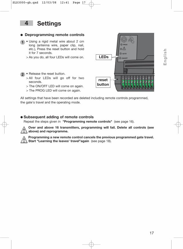
● Deprogramming remote controls
• Using a rigid metal wire about 2 cmlong (antenna wire, paper clip, nail,etc.), Press the reset button and holdit for 7 seconds.
> As you do, all four LEDs will come on.
1
• Release the reset button. > All four LEDs will go off for two
seconds.> The ON/OFF LED will come on again.> The PROG LED will come on again.
2
ON/OFF
AUTO
PROG
LEDs
resetbutton
All settings that have been recorded are deleted including remote controls programmed, the gate's travel and the operating mode.
SLD3000-gb.qxd 12/03/08 12:41 Page 17

18
Settings4
❏ Programming the travel of the gate.Somfy's electronics automatically memorise:• The motor torque needed to control the gate when operating normally.
This programming subsequently enables any abnormal strain on the motorisation to bedetected.
• The travel required for the complete opening and closing of the leaves with locationmarking of the stops.
To begin the programming process, the leaves must be closed. Keep at a normaldistance from the gate and follow the steps below:
Once these 4 steps have been completed, the PROG LED goes off indicating the end of theoperations to programme the gate's travel path.This must be a full cycle (2 complete and uninterrupted openings/closings). If it is interrupted,the process is simply postponed and will resume the next time the gate is opened.
• Make a long press on the remotecontrol button.
> After a few seconds, the gates willslowly open.
* If the gate does not open properly,check the wiring of the motor asindicated below.
1
• Once the gate is open, make anotherlong press on the remote controlbutton.
> The gate closes.
2
• Press the same button again.> The gates open, still at a slow speed.
3
• Press the button one last time.> The gate closes.
4
SLD3000-gb.qxd 12/03/08 12:41 Page 18

19
En
gli
sh
Settings4
❏ Automatic mode settings.● Usage precautions
To use your gate in automatic mode, the standard EN 12453 requires that thefollowing accessories be installed. Your SLD is designed tobe connected to them.• a set of photocells (see description and wiring on page
24),• an orange LED (see description and wiring on page 25),• zone lighting
● Checking that settings are correct
Make a long press on the remote control
Press once more to stop the gate in the middle of its travel.
Cut mains power for at least 5 seconds.
Restore mains power.
Make another long press on the remote control.
The gate MUST continue in the opening direction.
If the gate does not open correctly:• check the wiring (see page 13) and reverse the terminals if necessary.Once the wiring has been reversed, the programming of the gate's travel will have tobe restarted.
5
4
3
2
1
• Place a remote control on thecrosshairs inscribed on the motorunit's casing:
> The AUTO LED is off.
1
• Make a long press on the remotecontrol button until the AUTO LEDcomes on. Release the button.
> The AUTO LED blinks.
2
● Automatic modeAfter opening, the gates close again automatically after a preset length of time Automatic mode will function after the cells have been wired and configured as below:
AUTO
PROG
AUTO
PROG
SLD3000-gb.qxd 12/03/08 12:41 Page 19
20
Settings4
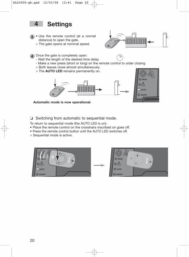
❏ Switching from automatic to sequential mode.To return to sequential mode (the AUTO LED is on):• Place the remote control on the crosshairs inscribed on goes off.• Press the remote control button until the AUTO LED switches off.> Sequential mode is active.
ON/OFF
AUTO
PROG
ON/OFF
AUTO
PROG
ON/OFF
AUTO
PROG
Automatic mode is now operational.
• Use the remote control (at a normaldistance) to open the gate.
> The gate opens at nominal speed.
3
Once the gate is completely open:- Wait the length of the desired time delay. - Make a new press (short or long) on the remote control to order closing> Both leaves close almost simultaneously.> The AUTO LED remains permanently on.
4
SLD3000-gb.qxd 12/03/08 12:41 Page 20

1 m
21
En
gli
sh
Use
■ Operating the lightingThe zone lighting comes on each time the gates are activated. They go off automatically 2minutes after movement has ended.
■ Operation in sequential mode
● Complete opening• Make a long press on the remote
control.> The gate must open.Another press (short or long) will order the gate to close.
● Pedestrian opening (if programmed)• Make a short press on the remote
control.> The gate must open partially.Another press (short or long) will order the gate to close.
It is possible to leave the gate open by tur-ning off the time delay by a short press onthe key on the remote control.
A further short press on the key of theremote control will cause the gate to close.
■ Operation in automatic modeIn automatic mode, a short press on the key on the remote control will cause the gateto open. It will close automatically after the time delay previously set by you.
STOP
SLD3000-gb.qxd 12/03/08 12:41 Page 21

22
Use
■ Changing the battery • Remove the clip from the remote control
and lift off the cover.• Remove the battery with a screwdriver
and replace it (3V CR 2430 or 3V CR2032).Battery life is generally 2 years.Used batteries are to be returned to the distributor or discarded in a waste reception/sorting centre.
■ Using the remote controlIf your vehicle has air conditioning and a metal-coated windscreen, aim the remote control atthe windscreen's black strip or through one of the untreated side windows.
■ Customising remote controlsThe coloured clips provided enable the remote controls to be customised.
■ Unlocking/locking the motor
By putting the motors into the unlockedposition , the gate may be operatedmanually in the event of a power outage.The gate is then totally free, open and closeit carefully.
3VCR 2032
+
Always relock the motor before thepower is restored. The handle must
be in the locked position .
For safety reasons, these operationsmust be carried out with the
electrical supply off. Even if there is apower cut, the supply may be restored atany time.
Never unlock or lock the motorwhile the gate is moving
(electrically or manually operated)!
SLD3000-gb.qxd 12/03/08 12:41 Page 22

23
En
gli
sh
Troubleshooting
■ SLD is not responding to remote control commands
● The ON/OFF LED does not light up when energised.Check the mains power.Check the power supply cable.Check the fuse.
● The DANGER LED remains on permanently.This signal indicates a photocell defect.
Check the alignment of the photocells.Check the photocells' power supply.Check the presence of photocells in automatic mode.
● The ON/OFF LED blinks slowly.Power malfunction: Call the hotline.Load too heavy: Too much wind or gate too heavy.
● The ON/OFF LED blinks quickly.Motor overheated: Wait for it to cool down.Short-circuit at motor output/outputs: Call the hotline.
● The motor does not start or moves in the wrong direction.Check the connections to the electronics.Check the position of the motor locking handle.Check the wiring of the motor, reverse if necessary (see page 13).
● The remote control's range has been lowered.Check the antenna wire.Check the transmitter battery.Environmental disturbance (such as electricity pylons or iron walls).Provide for an outside antenna.
■ Other problems For all other problems or requests for information about your SLD, you can call our Somfycustomer support technicians:0113 391 3030 - Monday to Friday, 8:45 - 17:00.
SLD3000-gb.qxd 12/03/08 12:41 Page 23

24
Accessories - Description and connections
Photocells are used to halt or reverse the gate's movement if an obstacle isdetected.A set of photocells may be installed. Each set of photocells is comprised of:• a transmitting cell (EC),• a receiving cell (RC).
24 V ac/dc
0 V C NC NO
1 2 3 4 5 1 2
24 V ac/dc
0 V
CRCE
● Wiring diagram for a set of photocells
● Placing the cellsIn order to make wiring simpler, place thereceiving cell on the gatepost where theelectronic motor is installed.
2 10 m40 cm
max. 20 cm
■ Photocells 2400599
● Safety instructionThe cells must be checked every 6 months to make sure they are in good working order. To doso, cover one cell with your hand as the gate closes. It should stop closing.
Before connecting the cells,remove the wire (shunt) between
terminals 3 and 4 in the electronic box.
EC RC
SLD3000-gb.qxd 12/03/08 12:41 Page 24

The backup battery ensures that the gate will operate in the eventof an electric failure, albeit at slow speed.It is connected and integrated directly intothe motor's electronic housing.
• Endurance: 10 continuous cycles or 24hours on a gate in perfect condition.
• Charge time before optimum battery use:48 hours.
• Battery life: 3 years.For best possible battery life, cut the electric power to your gate 3 times a year in order to run the battery for a few cycles.
Caution: do not run the cable fromthe battery on top of the mains
supply cable.
25
En
gli
sh
The orange LED signals theactivation of the motorisationmechanisms.It starts blinking two secondsbefore the gate begins to move.
■ Backup battery 2400479
■ Orange LED 2400596
Accessories - Description and connections
ON/OFF
AUTO
PROG
NO!
SLD3000-gb.qxd 12/03/08 12:41 Page 25

26
Accessories - Description and connections
■ Key switch 2400597
■ Intercom 2400463
1 m
SLD3000-gb.qxd 12/03/08 12:42 Page 26

27
En
gli
sh
Accessories - Description and connections
T1 C1 R1 V R3 T2 C2 R2 T3 C3 H P2 M P1 + H E – V
T1 C1 R1 V R3 T2 C2 R2 T3 C3 H P2 M P1 + H E – V
■ Digital code 2400581
1 m
SLD3000-gb.qxd 12/03/08 12:42 Page 27

28
Accessories - Description and connections
■ 2-button remote control 2400549
■ 4-button remote control CODE
2400576
■ Remote antenna 2400472
A wider-range remote antenna may be usedto replace the wire antenna.It is to be placed atop the gatepost, andmust be unencumbered.It is connected to the electronic box:the core of the wire into terminal 1, thegrounding strand into terminal 2.
SLD3000-gb.qxd 12/03/08 12:42 Page 28
somfy.co.uk
We
are
cons
tant
ly s
eeki
ng t
o d
evel
op a
nd im
pro
ve o
ur m
odel
s, a
nd t
here
fore
, w
e re
serv
e th
e rig
ht t
o m
odify
the
m a
t an
y tim
e, in
any
way
we
may
d
eem
use
ful.
Pho
tos
may
diff
er f
rom
act
ual p
rod
uct.
©S
OM
FY.
GM
D03
0110
-S
OM
FY S
AS
, ca
pita
l of
20,0
00,0
00,
regi
ster
ed in
Bon
nevi
lle 3
03.9
70.2
30
Util
isab
le e
n U
E,
CH
Usa
ble
in E
U,C
HB
ruik
baa
r in
EU
, C
HU
tiliz
able
en
la U
E,
CH
Vers
ion
1 –
02/2
008
-505
5382
A
SOMFY LTDMoorfield RoadYeadonLeedsWest YorkshireLS19 7BNTel. 0113 391 3030Fax. 0113 391 3010
SLD3000-gb.qxd 12/03/08 12:41 Page 1


