37
Slide 1 1 April 2006 Texas Instruments Linearization Fundamentals Driving Digital Pre-Distortion and the GC5322!
| Date post: | 17-Dec-2015 |
| Category: |
Documents |
| Upload: | sherilyn-norton |
| View: | 216 times |
| Download: | 0 times |

Slide 11
April 2006
Texas Instruments
Linearization Fundamentals
Driving Digital Pre-Distortion
and the GC5322!
Slide 2
2
PRELIMINARY
Subject to Change
Agenda
Introduction and Impact
Origin and History of the Problem Linearization Fundamentals Polynomial Power Amplifier Modeling Crest Factor Reduction Digital Pre-Distortion
System Implementation Crest Factor Reduction and Digital Pre-Distortion Adaptive Memory Pre-distortion of Power Amplifiers
Conclusions

Slide 3
3
PRELIMINARY
Subject to Change
Introduction and Impact
The demands for spectrally efficient modulation schemes have increased; however these schemes are subject to severe intermodulation distortion (IMD) when the power amplifiers (PA) are operated near saturation
Unfortunately, PAs are most efficient when operated near saturation
1980 1985 1990 1995 2000 2005 2010
AMPS/D-AMPS
TDMA/GSM
EDGE/CDMA
30kHz BW@ 800MHz
CDMA2000
WCDMA
WiMAX.16a/d/e
Super 3G& 4G
1G - AnalogCellular
2G - Digital
Cellular
3G – Digital
WidebandCellular
4G Cellular
&WiMAX
2015
<=200kHz BW@ 8-900MHz
200kHz BW@ 800MHz
1.25MHz BW@ 1.9GHz
5MHz BW@ 2.1GHz
10-40MHz BW@ 2.5, 3.5 & 5GHz
20MHz BW@ 2.1GHz
Cellu
lar
Channel
BW @
Ban
d
Incr
ease
d sig
nal
bandwid
th a
nd com
plexi
ty
A big
chal
lenge
for
MCPA d
esig
ners!

Slide 4
4
PRELIMINARY
Subject to Change
Introduction and Impact
High Power RF PA’s (>10W) use multiple driver stages to amplify an input signal.
Different PA architecture’s (Class A, AB, C, etc …) offer various degrees of linearity, cost and efficiency.
RF PA’s are notoriously inefficient – Air is a convenient but poor transmission medium.
RF PA’s are designed (tuned) for specific frequency range and bandwidth
MCPA ~= wideband RF PA, does not have to process multiple carriers
PA Gain is usually fixed – so pre-amps may be required to drive the PA input.
PA
TX Board
If Gain = 30dB,
RFout =50dBm(100W)
RFin ==20dBm
@ >800MHz
3 to 4 gain stages typical
DAC IF->RFDUC
FromBaseband
50 OhmTypicalInput
Antenna
A
Pre-Amp

Slide 5
5
PRELIMINARY
Subject to Change
Introduction and Impact
Linearization techniques allow a PA to be operated at higher power with minimal IMD increases, thus greater efficiency
Recent technological advances have made digital pre-distortion the focus of research efforts
Crest factor reduction (CFR) further increases the efficiency of the PA by reducing the peak-to-average ratio (PAR) of the transmitted signal
Pre-Distortion No No Yes Yes
CFR No Moderate Moderate Yes
Tx Power 10W 10W 10W 10W
PAR 12dB 9dB 9dB 6dB
Backoff 15dB 12dB 9dB 6dB
PA Power Rating 320W 160W 80W 40W
Efficency 5% 9% 18% 30%
Power Dissipation 120W 101W 45W 7W
Theoretical Performance of Class AB PA

Slide 6
6
PRELIMINARY
Subject to Change
Origin and History of the Problem
The trade-off between efficiency and linearity is the primary concern for PA designers
A PA operating at a high percentage of its power rating requires external linearization to maintain linearity
The linearization of the PA reduces back-off, thus increasing efficiency
1. Linearization Fundamentals

Slide 7
7
PRELIMINARY
Subject to Change
Origin and History of the Problem
Accurate representation of the nonlinear effects in PAs is achieved using a polynomial expression, as follows
The coefficients represent the linear gain, and the gain constants for the quadratic and cubic nonlinearities
A system with memory (phase) versus memory effects (non-linearities)
Envelope and frequency memory effects
2. Polynomial Power Amplifier Modeling

Slide 8
8
PRELIMINARY
Subject to Change
Origin and History of the Problem
Two tone test is useful for measuring spectral regrowth in a nonlinear and memoryless system
2. Power Amplifier Characterization

Slide 9
9
PRELIMINARY
Subject to Change
Origin and History of the Problem
Theoretically, only odd-degree nonlinearities generate in-band distortion products
The simplified polynomial PA model is expressed as follows
2. Power Amplifier Characterization
Slide 10
10
PRELIMINARY
Subject to Change
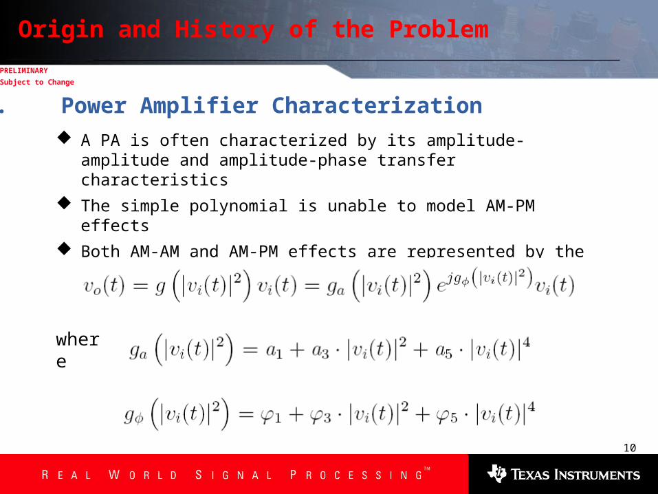
Origin and History of the Problem
A PA is often characterized by its amplitude-amplitude and amplitude-phase transfer characteristics
The simple polynomial is unable to model AM-PM effects
Both AM-AM and AM-PM effects are represented by the complex baseband model
2. Power Amplifier Characterization
where

Slide 11
11
PRELIMINARY
Subject to Change
Origin and History of the Problem
A simple case considering only 3rd degree nonlinearities in the AM-AM and AM-PM transfer characteristics is represented by the following
In the linear range, the PA can be characterized by the following
2. Power Amplifier Characterization
and

Slide 12
12
PRELIMINARY
Subject to Change
Origin and History of the Problem
2. Power Amplifier Characterization
AM-AM Characteristic AM-PM Characteristic

Slide 13
13
PRELIMINARY
Subject to Change
Origin and History of the Problem
The DPD optimal performance depends greatly on signal characteristics
Multi-carrier signals can have a PAR as high as 13dB increasing the level of back-off to maintain acceptable IMD levels
The application of CFR allows the PA to operate at higher input/output power levels while maintaining linearity at the output of the PA
Achieved through pulse generation and digital clipping
3. Crest-Factor Reduction

Slide 14
14
PRELIMINARY
Subject to Change
Origin and History of the Problem
Preferred PA bias point for a typical modulated signal
3. Crest-Factor Reduction

Slide 15
15
PRELIMINARY
Subject to Change
Origin and History of the Problem
Preferred PA bias point for a CFR signal
3. Crest-Factor Reduction

Slide 16
16
PRELIMINARY
Subject to Change
Origin and History of the Problem
Pre-distortion effectively performs a mathematical inversion of the Volterra PA model
The output of the pre-distortion processor is described by the following
The PA is linearized when
4. Digital Pre-Distortion

Slide 17
17
PRELIMINARY
Subject to Change
Origin and History of the Problem
Digital pre-distortion (DPD) has become an effective linearization technique due to the renewed possibilities offered by DSP
Adaptive PD designs use feedback to compensate for PA variations Look-up tables are updated to achieve optimal pre-distortion by
comparing PD input to PA output The PD function is expressed as a complex polynomial
4. Digital Pre-Distortion
where

Slide 18
18
PRELIMINARY
Subject to Change
Origin and History of the Problem
Digital pre-distortion (DPD) requires feedback for sample-by-sample adaptation 5 times that of the signal bandwidth
Multi-carrier systems use signal bandwidths of up to 20MHz today, thus the feedback bandwidth must be 100MHz to compensate 3rd and 5th order IMD
Least-mean-square (LMS) is a popular gradient based optimization algorithm that requires wideband feedback
4. Digital Pre-Distortion

Slide 19
19
PRELIMINARY
Subject to Change
System Implementation
The combination of CFR and digital pre-distortion were investigated In this case, linearization was achieved with a traditional wideband
feedback LMS algorithm The CFR technique used was proposed by Texas Instruments using the
GC1115 signal pre-processor Four stages ensure that the output PAR is reduced to values from 5 to
8dB, as specified by the user Performance results were compared using a Cree Microdevices 30W PA
operating at 1.96GHz and a signal bandwidth of 1.25MHz The PAR of the IS-95 signal was reduced from 9.6dB to 5dB
1. Crest-Factor Reduction and Digital Pre-Distortion

Slide 20
20
PRELIMINARY
Subject to Change
System Implementation
Complex Canceling Pulse
1. Crest-Factor Reduction and Digital Pre-Distortion

Slide 21
21
PRELIMINARY
Subject to Change
System Implementation
Corrected and uncorrected signal with canceling peaks and detection threshold
1. Crest-Factor Reduction and Digital Pre-Distortion

Slide 22
22
PRELIMINARY
Subject to Change
System Implementation
Typical Peak Detection and Cancellation through Pulse Injection
Input Signal Output Signal
Cancellation Signal
+
-
1. Crest-Factor Reduction and Digital Pre-Distortion

Slide 23
23
PRELIMINARY
Subject to Change
System Implementation
XPAAgilent 4432B
Down-Converter
LO
PC
Pre-Distorted Input Signal
Analog
RF
Analog
IF
DUT
Waveform Generator
Tektronics TDS224 Oscilloscope
Attenuator
~20dB
1. Crest-Factor Reduction and Digital Pre-Distortion
Hardware Implementation of Wideband Pre-Distortion

Slide 24
24
PRELIMINARY
Subject to Change
System Implementation
ACPR improvement with respect to output power
1. Crest-Factor Reduction and Digital Pre-Distortion

Slide 25
25
PRELIMINARY
Subject to Change
System Implementation
Power and efficiency improvement
The ACPR measurements were recorded according to specifications with a 30kHz marker at and offset of 885kHz
Results were limited by the performance limitations of the test bed
1. Crest-Factor Reduction and Digital Pre-Distortion

Slide 26
26
PRELIMINARY
Subject to Change
System Implementation
2. Adaptive Memory Pre-distortion of Power Amplifiers
The term memory effects refer to the bandwidth-dependant nonlinear effects often present in PAs.
These encompass envelope memory effects and frequency response memory effects.
Envelope memory effects are primarily a result of thermal hysteresis and electrical properties inherent to PAs.
Frequency memory effects are due to the variations in the frequency spacing of the transmitted signal and are characterized by shorter time constants.

Slide 27
27
PRELIMINARY
Subject to Change
System Implementation
2. Adaptive Memory Pre-distortion of Power Amplifiers
Memory Polynomial Pre-Distortion Implementation
And (D=2)
Where (K=7)

Slide 28
28
PRELIMINARY
Subject to Change
System Implementation
2. Adaptive Memory Pre-distortion of Power Amplifiers
This traditional approach uses and LMS algorithm to adapt the PD coefficients on a sample-by-sample basis. The memory PA model has D=1 (delay) and K=5 (order).
Simulated Performance of Wideband Pre-Distortion

Slide 29
29
PRELIMINARY
Subject to Change
System Implementation
2. Adaptive Memory Pre-distortion of Power Amplifiers
Simulated Performance of Wideband Pre-Distortion The memory PA model is characterized by the following AM-AM and AM-PM curves

Slide 30
30
PRELIMINARY
Subject to Change
System Implementation
2. Adaptive Memory Pre-distortion of Power Amplifiers
Simulated Performance of Wideband Pre-Distortion DPD = 0: the LMS algorithm indicates an ACPL improvement of -3dB and an ACPH improvement
of 3dB. DPD = 1: the LMS algorithm indicates an ACPL improvement of -15dB and an ACPH improvement
of -11dB.

Slide 31
31
PRELIMINARY
Subject to Change
System Implementation
2. Adaptive Memory Pre-distortion of Power Amplifiers Simulated Performance of Wideband Pre-Distortion
DPD = 2: the LMS algorithm indicates an ACPL improvement of -24dB and an ACPH improvement of -23dB. DPD = 3: the LMS algorithm indicates an ACPL improvement of -24dB and an ACPH improvement of -20dB.

Slide 32
32
PRELIMINARY
Subject to Change
System Implementation
2. Adaptive Memory Pre-distortion of Power Amplifiers Hardware Implementation of Wideband Pre-Distortion
TI offers the complete high-performance signal chain including: DAC5687, CDCM7005, TRF3761, ADS5444, and TRF3703.

Slide 33
33
PRELIMINARY
Subject to Change
System Implementation
2. Adaptive Memory Pre-distortion of Power Amplifiers
Typical Doherty Amplifier configuration and Performance Results

Slide 34
34
PRELIMINARY
Subject to Change
System Implementation
2. Adaptive Memory Pre-distortion of Power Amplifiers
Hardware Implementation of Wideband Pre-Distortion

Slide 35
35
PRELIMINARY
Subject to Change
Conclusions
CFR improves DPD performance CFR uses EVM and ACLR to tradeoff for added efficiency Depending on modulation schemes the relative percentages may vary OFDM modulations are sensitive to EVM 3GPP modulations are sensitive to ACLR
EVM
Efficiency
ACLR
3GPP Relative Tradeoffs
EVM
Efficiency
ACLR
OFDM Relative Tradeoffs

Slide 36
36
PRELIMINARY
Subject to Change
Conclusions
Relative to a PA that operates normally under backoff, DPD adds additional hardware (cost) and system complexity to tradeoff for added efficiency
DPD can effectively remove the negative effects of CFR enabling even greater levels of efficiency
Cost
DPD
Complexity
DPD Relative Tradeoffs
EVM
Efficiency
ACLR
CFR+DPDCFR+DPD

Slide 37
37
PRELIMINARY
Subject to Change
Questions


![LINEARIZATION OF RF FRONT ENDS...Linearization is the reduction of distortion in an RFFE to acceptable levels. There are a plurality of linearization techniques in the literature [1],](https://static.documents.pub/doc/80x56/606f006d24a9d575cc611c61/linearization-of-rf-front-ends-linearization-is-the-reduction-of-distortion.jpg)


![Reduction of Crosstalk Distortion in 5G€¦ · [Document title] Reduction of Crosstalk Distortion in 5G Relaxed Isolation-based Linearization for sub-6 GHz Advanced Antenna Systems](https://static.documents.pub/doc/80x56/60de12906c9e0d026d67ff1c/reduction-of-crosstalk-distortion-in-5g-document-title-reduction-of-crosstalk.jpg)


