A Sierra Monitor Company APPLICABILITY & EFFECTIVITY This manual provides instructions for the following FieldServer products: Description PS56-BAS-xxx PS56-FIR-xxx PS56-PRO-407 The instructions are effective for the above as of September 2012 SlotServer Configuration Manual Kernel Version: 1.04 Document Revision: 5
Transcript
A Sierra Monitor Company
APPLICABILITY & EFFECTIVITY This manual provides instructions for the following FieldServer products: Description PS56-BAS-xxx PS56-FIR-xxx PS56-PRO-407 The instructions are effective for the above as of September 2012
SlotServer Configuration Manual
Kernel Version: 1.04 Document Revision: 5
SlotServer Configuration Manual Table of Contents
ProSoft Technology, Inc. is the exclusive provider of FieldServer SlotServers. For Technical Support call +1 661.716.5100
1.1 About this Product ......................................................................................................................................... 4 1.2 Required Configuration for the SlotServer .................................................................................................... 4
2 Steps for implementation of a SlotServer Project........................................................................................... 5
2.1 Install the FieldServer Utilities ....................................................................................................................... 5 2.2 Load the SlotServer Configuration into the SlotServer .................................................................................. 5 2.3 Program the ControlLogix CPU to communicate with the SlotServer. .......................................................... 5 2.4 Commission the third party network. ............................................................................................................ 5
3 Configuring the CPU interface to the SlotServer ............................................................................................. 6
3.1 CPU interface Description .............................................................................................................................. 6 3.2 Data Array Parameters .................................................................................................................................. 6 3.3 Configuring the SlotServer as a Logix I/O Server ........................................................................................... 7 3.4 Client Side Connection Parameters ............................................................................................................... 7 3.5 Client Side Node Parameters ......................................................................................................................... 7 3.6 Client Side Map Descriptor Parameters ......................................................................................................... 8
3.6.1 SlotServer Specific Map Descriptor Parameters ..................................................................................... 8 3.6.2 Driver Specific Map Descriptor Parameters ........................................................................................... 8 3.6.3 Map Descriptor Example ........................................................................................................................ 9
4 Programming the ControlLogix CPU for a small SlotServer Interface ............................................................ 10
4.1 Step 1: Establish an RSLogix project ............................................................................................................ 10 4.2 Step 2: Add and configure the SlotServer as an IO Module......................................................................... 10 4.3 Step 3: Write Ladder Program to get Input Data from Data Arrays ............................................................ 12 4.4 Step 4: Write Ladder Program to Send Output Data to Data Arrays ........................................................... 15 4.5 Step 5: Download the RSLogix Program and Run ........................................................................................ 15 4.6 Step 6: Set up the third party connection .................................................................................................... 15
5 Programming the ControlLogix CPU for larger SlotServer Interfaces ............................................................ 16
5.1 Multiple Input Data Arrays .......................................................................................................................... 16 5.2 Accessing Multiple Output Data Arrays ....................................................................................................... 16 5.3 Loading Data_Array Values from the FieldServer’s Non-Volatile Memory ................................................. 18
Appendix A. Useful Features ................................................................................................................................ 21
Appendix A.1. How to obtain Node Status from the SlotServer .............................................................................. 21
Appendix B. Troubleshooting ............................................................................................................................... 22
Appendix A.1. SlotServer block number [ 0 ] out of range! ..................................................................................... 22 Appendix A.2. Driver Error screen returns “Illegal Protocol” Error. ........................................................................ 22 Appendix A.3. SlotServer output image data transfer stops after a few hours when keeping RSWho open to browse the rack. ...................................................................................................................................................... 22
Appendix C. Vendor Information ......................................................................................................................... 23
Appendix A.4. SlotServer in Remote Allen Bradley Racks ....................................................................................... 23 Appendix A.5. Installing SlotServer on a Remote Rack using CNB Cards ................................................................. 23
Appendix A.6. Dealing with ControlLogix RPI Settings ............................................................................................ 27 Appendix A.7. Rules for Naming Logix driver Data Arrays ....................................................................................... 27
SlotServer Configuration Manual Table of Contents
ProSoft Technology, Inc. is the exclusive provider of FieldServer SlotServers. For Technical Support call +1 661.716.5100
Appendix D. Reference ........................................................................................................................................ 30
Appendix A.8. Description of Data Transfer Process ............................................................................................... 30 Appendix A.9. The IO image header ........................................................................................................................ 32 Appendix A.10. Available Data Types for Data Arrays ............................................................................................. 32 Appendix A.11. Permissible Values for Configuration File Variables ....................................................................... 33
Appendix A.11.1. Common Information ........................................................................................................... 33 Appendix A.11.2. Data Arrays .......................................................................................................................... 33 Appendix A.11.3. Data Array Function ............................................................................................................. 34 Appendix A.11.4. Connections/ Adapters ......................................................................................................... 35 Appendix A.11.5. Nodes ................................................................................................................................... 35 Appendix A.11.6. Map Descriptors ................................................................................................................... 37
SlotServer Configuration Manual Page 4 of 37
ProSoft Technology, Inc. is the exclusive provider of FieldServer SlotServers. For Technical Support call +1 661.716.5100
INTRODUCTION 1
1.1 About this Product
The SlotServer Configuration Manual provides the information necessary to configure the SlotServer, allowing an Allen Bradley ControlLogix platform to pass data between a ControlLogix CPU and other third party communications protocols supported by the SlotServer. The SlotServer uses implicit communications between the CPU and the SlotServer and is consequently treated as an I/O Server in RSLogix.
When configured in remote rack applications, the SlotServer does not support the use of EN2T-A cards, but is compatible with EN2T-B cards.
The SlotServer Start-up guide covers information for installing the SlotServer; the Configuration Manual provides information on configuring the module to transfer data with the CPU on the ControlLogix Rack. Depending on the SlotServer Module ordered, supplementary driver manuals are provided for information on how to configure the third party protocols residing in the SlotServer.
1.2 Required Configuration for the SlotServer
To achieve data transfer between CPU tags and the SlotServer third party protocols, it is necessary to write and load a configuration into the SlotServer that tells the SlotServer how to map the ControlLogix Tags to the required protocol addresses. This configuration is written in a Comma Separated Variable (csv) file, and any text editor or spreadsheet program that supports csv format can be used for this purpose. FieldServer Technologies provides an example configuration file so that the configuration does not need to be written from scratch. Configuration parameters needed to exchange data between the CPU and the SlotServer data images (Data Arrays) are presented in Section 3. The appropriate driver manual supplement will describe how to map the data in and out of the Data Arrays for the relevant protocol.
The SlotServer configuration manual details basic and advanced techniques for the configuration of the SlotServer, and it is strongly advised that this manual is read before attempting to write the SlotServer Configuration.
FieldServer Technologies provides SlotServer configuration services if the user does not wish to perform the configuration themselves.
SlotServer Configuration Manual Page 5 of 37
ProSoft Technology, Inc. is the exclusive provider of FieldServer SlotServers. For Technical Support call +1 661.716.5100
STEPS FOR IMPLEMENTATION OF A SLOTSERVER PROJECT 2
2.1 Install the FieldServer Utilities
Refer to the Start-up guide for further information..
2.2 Load the SlotServer Configuration into the SlotServer
Refer to the SlotServer Start-up Guide for information on the FieldServer Graphic User Interface (FS-GUI).
2.3 Program the ControlLogix CPU to communicate with the SlotServer.
The sections that follow highlight a few examples on how this is done.
2.4 Commission the third party network.
Refer to standard commissioning guidelines for the protocol in question.
SlotServer Configuration Manual Page 6 of 37
ProSoft Technology, Inc. is the exclusive provider of FieldServer SlotServers. For Technical Support call +1 661.716.5100
CONFIGURING THE CPU INTERFACE TO THE SLOTSERVER 3
3.1 CPU interface Description
The SlotServer Data Images (Data Arrays) share data between the ControlLogix CPU tags (using the backplane for communication) and the FieldServer Logix driver. To map the Logix Driver, the Driver needs to be configured in the SlotServer Configuration. The information that follows details the configuration parameters that can be used for this driver. The driver can only act as an I/O Server (Adapter) to a ControlLogix CPU. The SlotServer presently works with ENBT Ethernet cards, but not EN2F. When configured in remote rack applications, the SlotServer does not support the use of EN2T-A cards, but is compatible with EN2T-B cards.
Max Nodes Supported
SlotServer Mode Nodes Comments
Server 1 Only one IO image connection supported
// Common Information FieldServer Title , System_Station_Address SlotServer Server v1.03d , 1
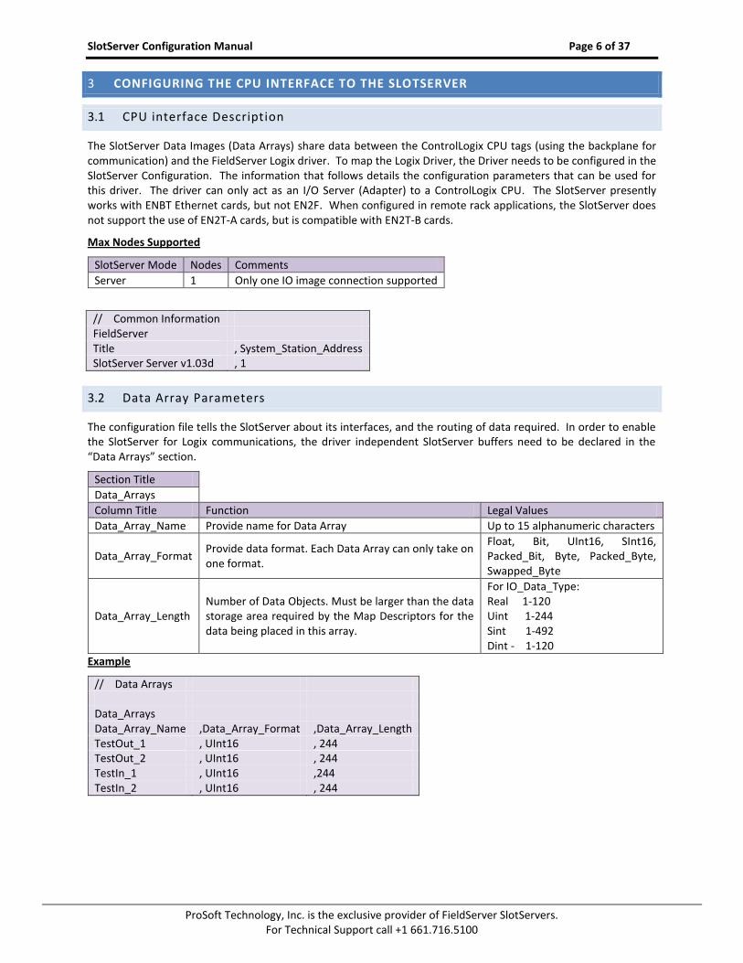
3.2 Data Array Parameters
The configuration file tells the SlotServer about its interfaces, and the routing of data required. In order to enable the SlotServer for Logix communications, the driver independent SlotServer buffers need to be declared in the “Data Arrays” section.
Section Title
Data_Arrays
Column Title Function Legal Values
Data_Array_Name Provide name for Data Array Up to 15 alphanumeric characters
Data_Array_Format Provide data format. Each Data Array can only take on one format.
Data_Array_Length Number of Data Objects. Must be larger than the data storage area required by the Map Descriptors for the data being placed in this array.
For IO_Data_Type: Real 1-120 Uint 1-244 Sint 1-492 Dint - 1-120
ProSoft Technology, Inc. is the exclusive provider of FieldServer SlotServers. For Technical Support call +1 661.716.5100
3.3 Configuring the SlotServer as a Logix I/O Server
The information that follows describes how to expand upon the factory defaults provided in the configuration files included with the SlotServer (See “.csv” sample files provided with the SlotServer).
The configuration file tells the SlotServer about its interfaces, and the routing of data required. In order to enable the SlotServer for Logix communications, the driver independent SlotServer buffers need to be declared in the “Data Arrays” section, the SlotServer virtual node(s) needs to be declared in the “Server Side Nodes” section, and the data to be provided to the Clients needs to be mapped in the “Server Side Map Descriptors” section. Details on how to do this can be found below.
Note that in the tables, * indicates an optional parameter, with the bold legal value being the default.
3.4 Client Side Connection Parameters
Section Title
Connections
Column Title Function Legal Values
Adapter Adapter Name ControlNet
Example
// Server Side Connections Connections Adapter ControlNet
3.5 Client Side Node Parameters
Section Title
Nodes
Column Title Function Legal Values
Node_Name Provide name for Node Up to 32 alphanumeric characters
Node_ID Virtual Node ID 0-15
Protocol Specify protocol used Logix_SS
Example
// Server Side Nodes Nodes Node_Name , Node_ID , Protocol SlotServer_CPU , 1 , Logix_SS
SlotServer Configuration Manual Page 8 of 37
ProSoft Technology, Inc. is the exclusive provider of FieldServer SlotServers. For Technical Support call +1 661.716.5100
3.6 Client Side Map Descriptor Parameters
3.6.1 SlotServer Specific Map Descriptor Parameters
Column Title Function Legal Values
Map_Descriptor_Name Name of this Map Descriptor Up to 32 alphanumeric characters
Function Function of Server Map Descriptor WRBC-to write into Input Image Data buffer RDBC-to read from Output Image Data buffer
3.6.2 Driver Specific Map Descriptor Parameters
Column Title Function Legal Values
Node_Name Name of Node to fetch data from
One of the node names specified in “Client Node Descriptor” above
IO_Data_Type Data type of IO image
Use same as used in RSLogix to add the module INT (16-bit integer) SINT (8-bit signed) DINT (32-bit double) REAL (32-bit float)
DA_Name_Start1
Name of Data Array to include in IO image data
One of the Data Array names from Section 3.2. Data Arrays must be named as follows: DaName_x where x is a positive integer value e.g. DaName_1
DA_Count Number of Data Arrays to include in IO image data
1-2002
Scan_Interval Rate at which IO image data is updated.
Use twice the rate of RPI, e.g.: RPI = 0.4s, Scan_Interval=0.2s
1 Refer to Appendix C.4 for information specific to naming Logix driver Data Arrays. 2 The update rate decreases as the number of blocks go up. For 25 blocks the update rate is 25*RPI = 25*0.1 = 2.5 seconds.
SlotServer Configuration Manual Page 9 of 37
ProSoft Technology, Inc. is the exclusive provider of FieldServer SlotServers. For Technical Support call +1 661.716.5100
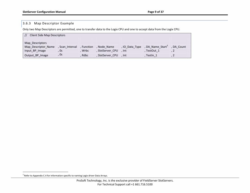
3.6.3 Map Descriptor Example
Only two Map Descriptors are permitted, one to transfer data to the Logix CPU and one to accept data from the Logix CPU.
// Client Side Map Descriptors Map_Descriptors Map_Descriptor_Name , Scan_Interval , Function , Node_Name , IO_Data_Type , DA_Name_Start
3 Refer to Appendix C.4 for information specific to naming Logix driver Data Arrays.
SlotServer Configuration Manual Page 10 of 37
ProSoft Technology, Inc. is the exclusive provider of FieldServer SlotServers. For Technical Support call +1 661.716.5100
PROGRAMMING THE CONTROLLOGIX CPU FOR A SMALL SLOTSERVER INTERFACE 4
The discussion that follows describes the basic steps to set up and test the system for transferring data between CPU tags and the SlotServer using the I/O image method. The quick Start example uses LonWorks as the example 3
rd Party Protocol. A hardcoded template filled with Lon variables is created. Each item uses a different amount of
bytes and the total adds up to 104 Lon Network Variables. This limit of 104 does not apply when using customized data items – the actual limit is 496 bytes. Refer to the Advanced Project to access more than 104 Network Variables.
4.1 Step 1: Establish an RSLogix project4
Use File/New to create a new project or File/Open to open an existing project.
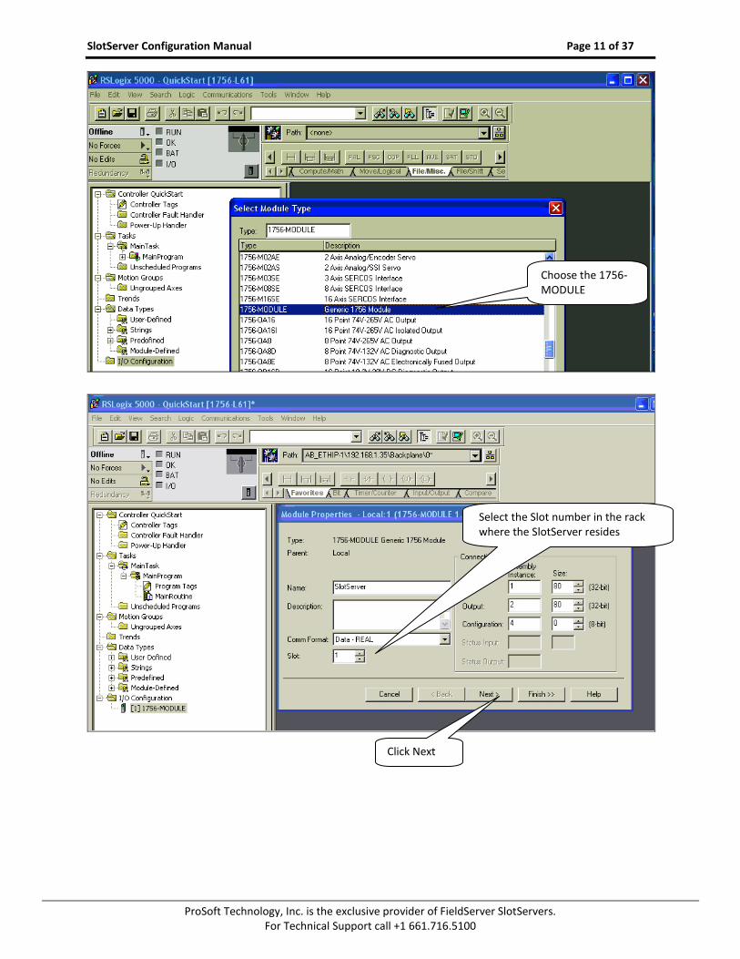
4.2 Step 2: Add and configure the SlotServer as an IO Module
Right-click on I/O Configuration and select “New Module”.
Choose the 1756-MODULE
4 Your Controller may be of a different type to the one shown in the example.
Select the slot number in the rack where the Controller resides.
SlotServer Configuration Manual Page 11 of 37
ProSoft Technology, Inc. is the exclusive provider of FieldServer SlotServers. For Technical Support call +1 661.716.5100
Choose the 1756-MODULE
Select the Slot number in the rack where the SlotServer resides
Click Next
SlotServer Configuration Manual Page 12 of 37
ProSoft Technology, Inc. is the exclusive provider of FieldServer SlotServers. For Technical Support call +1 661.716.5100
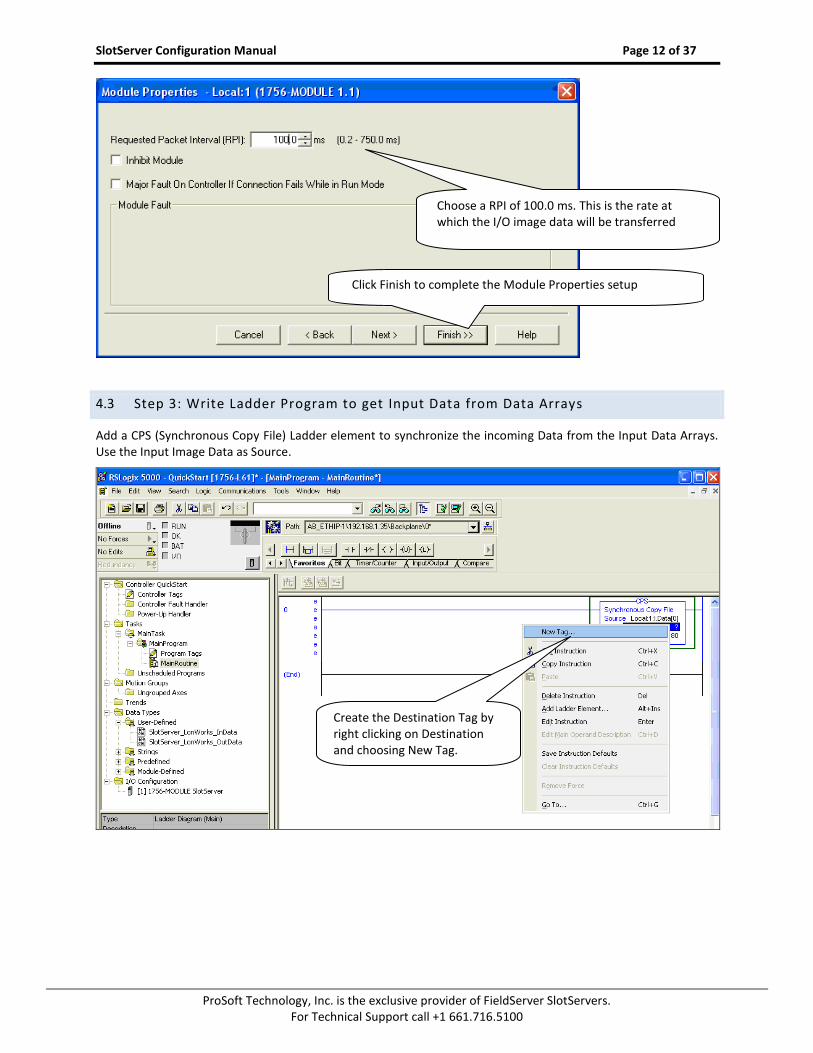
4.3 Step 3: Write Ladder Program to get Input Data from Data Arrays
Add a CPS (Synchronous Copy File) Ladder element to synchronize the incoming Data from the Input Data Arrays. Use the Input Image Data as Source.
Click Finish to complete the Module Properties setup
Create the Destination Tag by right clicking on Destination and choosing New Tag.
Choose a RPI of 100.0 ms. This is the rate at which the I/O image data will be transferred
SlotServer Configuration Manual Page 13 of 37
ProSoft Technology, Inc. is the exclusive provider of FieldServer SlotServers. For Technical Support call +1 661.716.5100
Add an EQU (Compare if equal) ladder element to check when the first Data Array has been received. The block number is at offset 2 of the input image.
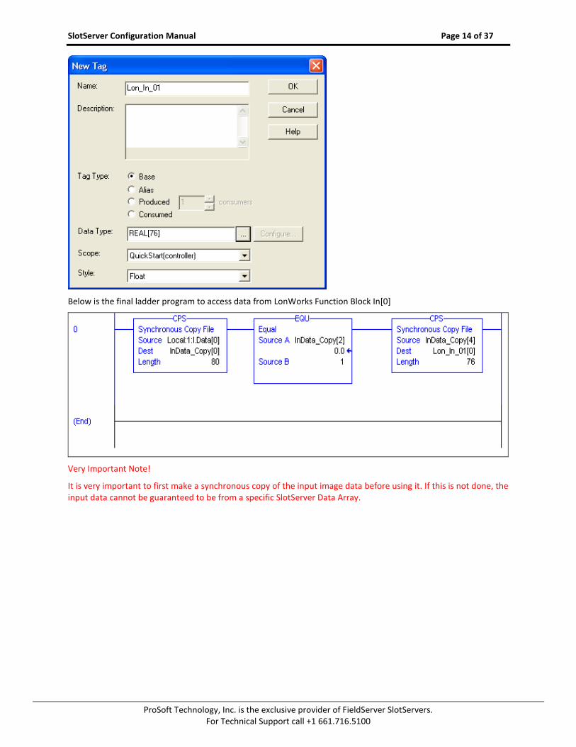
Finally, add another CPS ladder element to copy the LonWorks Data from the InData_Copy Tag to a new Controller Tag, called Lon_In_01. Also create the Tag by right clicking on Destination and choosing New Tag. The New Tag must be of type REAL and a dimension of 76.
Create a Controller Tag of Type REAL, dimension 80 for the Destination
SlotServer Configuration Manual Page 14 of 37
ProSoft Technology, Inc. is the exclusive provider of FieldServer SlotServers. For Technical Support call +1 661.716.5100
Below is the final ladder program to access data from LonWorks Function Block In[0]
Very Important Note!
It is very important to first make a synchronous copy of the input image data before using it. If this is not done, the input data cannot be guaranteed to be from a specific SlotServer Data Array.
SlotServer Configuration Manual Page 15 of 37
ProSoft Technology, Inc. is the exclusive provider of FieldServer SlotServers. For Technical Support call +1 661.716.5100
4.4 Step 4: Write Ladder Program to Send Output Data to Data Arrays
This step demonstrates how to write data to the Data Array Out[0]
Create a Controller Tag called Lon_Out_01 of type REAL[80].
Add a new rung to the Ladder program and add a MOV element to move a block number value of 1 into
Lon_Out_01[2].
Finally add a CPS (Synchronous Copy File) element to copy the full Lon_Out_01 tag into the Output Image Tag.
The LonWorks Data are present from Lon_Out_01[4] to Lon_Out_01[79]
You can create a User Defined Data Type to replace the type of Lon_Out_01 mapping the points to LonWorks point names.
Very Important Note!
It is very important to only update all the data of the Output Image Tag once using a Synchronous File Copy element. It is not permissible to update the block number into the Output Image Tag and then the data as this will cause an asynchronous transfer of data.
4.5 Step 5: Download the RSLogix Program and Run
Use the Who Active or Communications Path directly to Download and Run the Program on the Controller / CPU.
4.6 Step 6: Set up the third party connection
In this example, this step would involve binding the LonWorks variables using a LonWorks Network Manager.
SlotServer Configuration Manual Page 16 of 37
ProSoft Technology, Inc. is the exclusive provider of FieldServer SlotServers. For Technical Support call +1 661.716.5100
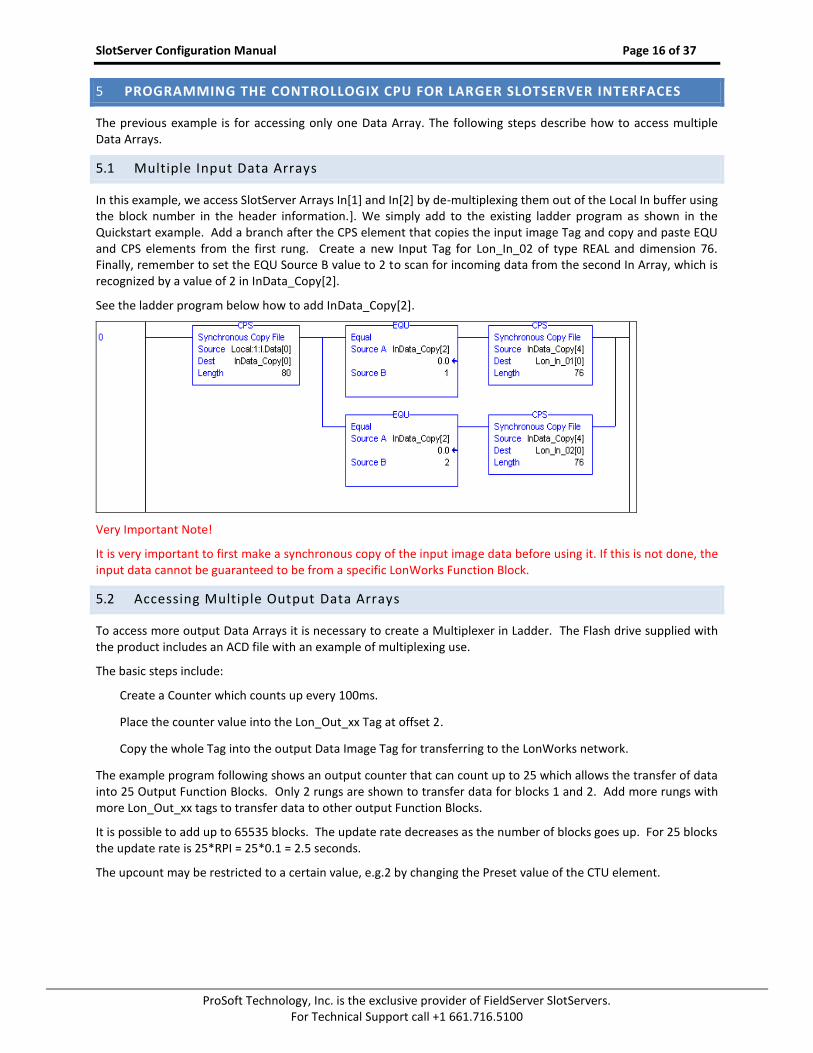
PROGRAMMING THE CONTROLLOGIX CPU FOR LARGER SLOTSERVER INTERFACES 5
The previous example is for accessing only one Data Array. The following steps describe how to access multiple Data Arrays.
5.1 Multiple Input Data Arrays
In this example, we access SlotServer Arrays In[1] and In[2] by de-multiplexing them out of the Local In buffer using the block number in the header information.]. We simply add to the existing ladder program as shown in the Quickstart example. Add a branch after the CPS element that copies the input image Tag and copy and paste EQU and CPS elements from the first rung. Create a new Input Tag for Lon_In_02 of type REAL and dimension 76. Finally, remember to set the EQU Source B value to 2 to scan for incoming data from the second In Array, which is recognized by a value of 2 in InData_Copy[2].
See the ladder program below how to add InData_Copy[2].
Very Important Note!
It is very important to first make a synchronous copy of the input image data before using it. If this is not done, the input data cannot be guaranteed to be from a specific LonWorks Function Block.
5.2 Accessing Multiple Output Data Arrays
To access more output Data Arrays it is necessary to create a Multiplexer in Ladder. The Flash drive supplied with the product includes an ACD file with an example of multiplexing use.
The basic steps include:
Create a Counter which counts up every 100ms.
Place the counter value into the Lon_Out_xx Tag at offset 2.
Copy the whole Tag into the output Data Image Tag for transferring to the LonWorks network.
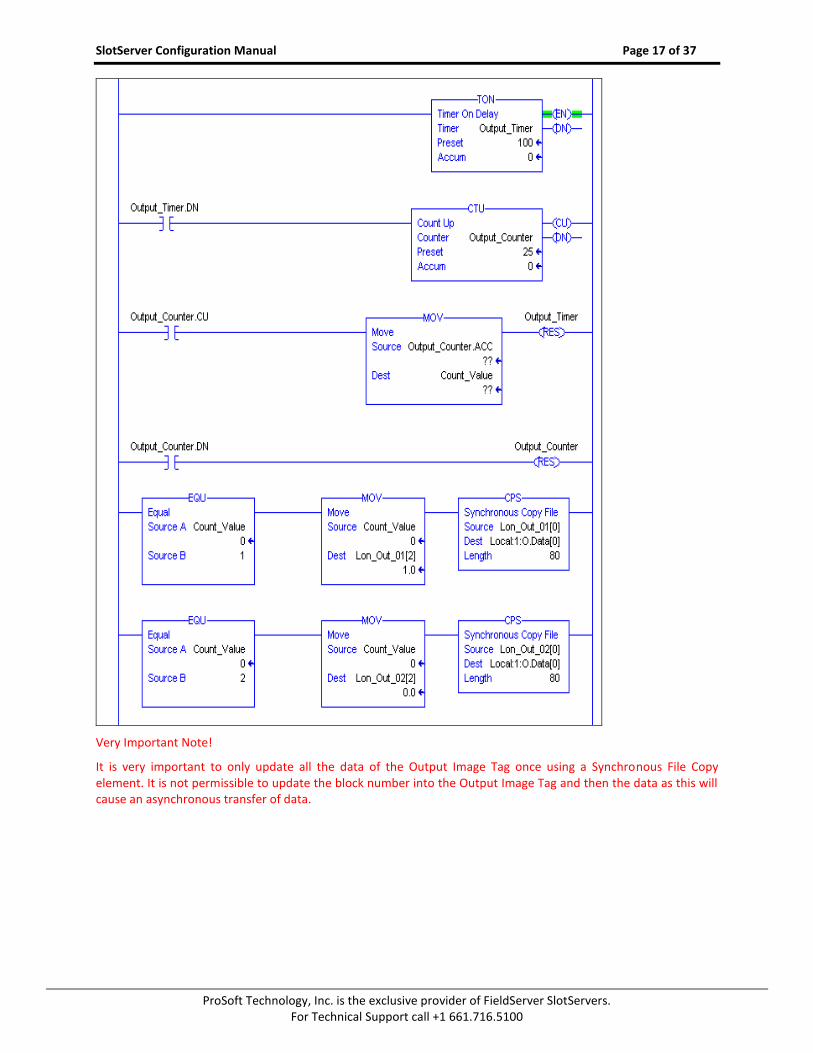
The example program following shows an output counter that can count up to 25 which allows the transfer of data into 25 Output Function Blocks. Only 2 rungs are shown to transfer data for blocks 1 and 2. Add more rungs with more Lon_Out_xx tags to transfer data to other output Function Blocks.
It is possible to add up to 65535 blocks. The update rate decreases as the number of blocks goes up. For 25 blocks the update rate is 25*RPI = 25*0.1 = 2.5 seconds.
The upcount may be restricted to a certain value, e.g.2 by changing the Preset value of the CTU element.
SlotServer Configuration Manual Page 17 of 37
ProSoft Technology, Inc. is the exclusive provider of FieldServer SlotServers. For Technical Support call +1 661.716.5100
Very Important Note!
It is very important to only update all the data of the Output Image Tag once using a Synchronous File Copy element. It is not permissible to update the block number into the Output Image Tag and then the data as this will cause an asynchronous transfer of data.
SlotServer Configuration Manual Page 18 of 37
ProSoft Technology, Inc. is the exclusive provider of FieldServer SlotServers. For Technical Support call +1 661.716.5100
5.3 Loading Data_Array Values from the FieldServer’s Non -Volatile Memory
If the value in the Data Array changes, the FieldServer can be configured to save this changed value to its Non-Volatile Memory up to 3 times a minute using the DA_Function_After_Store Parameter. On startup the value will be loaded from the Non-Volatile Memory into the Data Array. This value will only be stored 3 times a minute, so if more writes than that are done, the values will be stored in the Data Array, but not to the Non-Volatile Memory. Storing this value has performance impacts, so care must be taken to store this value only if needed.
There is a limit to the number of values that can be stored from a single data array:
ProSoft Technology, Inc. is the exclusive provider of FieldServer SlotServers. For Technical Support call +1 661.716.5100
TIMING PARAMETERS 6
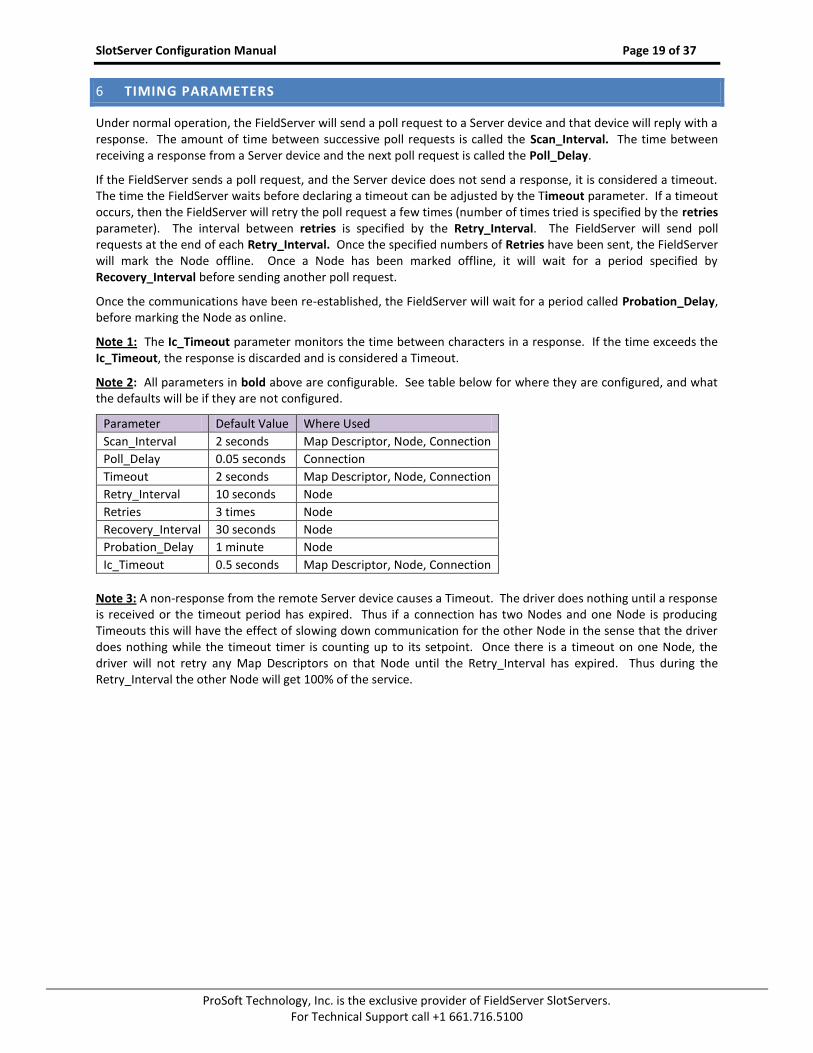
Under normal operation, the FieldServer will send a poll request to a Server device and that device will reply with a response. The amount of time between successive poll requests is called the Scan_Interval. The time between receiving a response from a Server device and the next poll request is called the Poll_Delay.
If the FieldServer sends a poll request, and the Server device does not send a response, it is considered a timeout. The time the FieldServer waits before declaring a timeout can be adjusted by the Timeout parameter. If a timeout occurs, then the FieldServer will retry the poll request a few times (number of times tried is specified by the retries parameter). The interval between retries is specified by the Retry_Interval. The FieldServer will send poll requests at the end of each Retry_Interval. Once the specified numbers of Retries have been sent, the FieldServer will mark the Node offline. Once a Node has been marked offline, it will wait for a period specified by Recovery_Interval before sending another poll request.
Once the communications have been re-established, the FieldServer will wait for a period called Probation_Delay, before marking the Node as online.
Note 1: The Ic_Timeout parameter monitors the time between characters in a response. If the time exceeds the Ic_Timeout, the response is discarded and is considered a Timeout.
Note 2: All parameters in bold above are configurable. See table below for where they are configured, and what the defaults will be if they are not configured.
Note 3: A non-response from the remote Server device causes a Timeout. The driver does nothing until a response is received or the timeout period has expired. Thus if a connection has two Nodes and one Node is producing Timeouts this will have the effect of slowing down communication for the other Node in the sense that the driver does nothing while the timeout timer is counting up to its setpoint. Once there is a timeout on one Node, the driver will not retry any Map Descriptors on that Node until the Retry_Interval has expired. Thus during the Retry_Interval the other Node will get 100% of the service.
SlotServer Configuration Manual Page 20 of 37
ProSoft Technology, Inc. is the exclusive provider of FieldServer SlotServers. For Technical Support call +1 661.716.5100
FieldServer Server Device
Poll
ResponseScan-Interval
Poll-Delay
Poll
Response
PollTimeout
Retry-interval
Poll
Poll
Recovery-Interval
Status: Node Online
Status: Node Offline
Poll
Response
Poll
Response
Poll
Response
Probation -Delay
Status: Node Online
Time
Retries
Figure I - SlotServer Timing Diagram
SlotServer Configuration Manual Page 21 of 37
ProSoft Technology, Inc. is the exclusive provider of FieldServer SlotServers. For Technical Support call +1 661.716.5100
Appendix A. USEFUL FEATURES
Appendix A.1. How to obtain Node Status from the SlotServer
By declaring the following Data Array, the Node Status field in the IO image header will be filled in with the Node Statuses of all Nodes declared on the SlotServer. If the communication status is good then the Node Status is set to 1. The communication status goes bad if it does not receive a response to a poll.
Typical Data Array Parameters are:
Section Title
Data_Arrays
Column Title Function Legal Values
Data_Array_Name Provide name for Data Array SlotServerNodes
Data_Format Provides Data format Bit
Data_Array_Length Number of Data Objects 1 to 256
Data_Array_Function Special function for Data Array Node_Status
// Data Arrays Data_Arrays Data_Array_Name , Data_Format , Data_Array_Length , Data_Array_Function SlotServerNodes , Bit , 256 , Node_Status
Note: The Data Array Name must be as shown for this function to work correctly.
SlotServer Configuration Manual Page 22 of 37
ProSoft Technology, Inc. is the exclusive provider of FieldServer SlotServers. For Technical Support call +1 661.716.5100
Appendix B. TROUBLESHOOTING
Appendix B.1. SlotServer block number [ 0 ] out of range!
It is necessary to put a non-zero buffer number in offset 2 of the output buffer, or to remove the related Map Descriptor if output buffers are not being used. Refer also to Appendix B.2.
Ensure that the configuration is not set to write to offset 0 of the output buffer. Offsets 0, 1 and 3 should be
clear and the correct non-zero buffer number should be written into offset 2.
If the output buffer is not being used then the corresponding Logix Map descriptor should be removed.
Appendix B.3. SlotServer output image data transfer stops after a few hours when keeping RSWho open to browse the rack.
This has been addressed in V1.04aB of the driver. Upgrade to V1.04aB or later.
SlotServer Configuration Manual Page 23 of 37
ProSoft Technology, Inc. is the exclusive provider of FieldServer SlotServers. For Technical Support call +1 661.716.5100
Appendix C. VENDOR INFORMATION
Appendix C.1. SlotServer in Remote Allen Bradley Racks
Note that the SlotServer cannot be used as a bridging device between racks and as such is not a connectable module in RSNetworx. However, the SlotServer may still be installed in a remote rack that has been connected to the CPU rack via some other connectable module.
Appendix C.2. Installing SlotServer on a Remote Rack using CNB Cards5
Appendix C.2.1. RSLogix configuration
In order to see the SlotServer from the CPU, the Hardware must be configured in RSLogix as follows:
Configure the cards in the local rack in the I/O Configuration section, including the CPU and the local CNB card.
Right click on the local CNB card and add the remote CNB card using the “New Module” function.
Right Click on the remote CNB card, and add the 1756 Backplane
Right Click on the 1756 Backplane and add the cards that are present in the remote rack, including the
SlotServer (As a generic I/O module-see earlier section on how to do this)
Save the RSLogix configuration, and download it to the PLC.
5 The principles for connecting other 1756 bridging cards to the SlotServer are similar.
SlotServer Configuration Manual Page 24 of 37
ProSoft Technology, Inc. is the exclusive provider of FieldServer SlotServers. For Technical Support call +1 661.716.5100
The finished I/O configuration should look similar to this:
Appendix C.2.2. RSNetWorx configuration
Open up RSNetWorx and add the two CNB Cards to the Network by dragging them onto the Network in the
Graph tab (Must be done with Edits Enabled). Follow the prompts on the screen to configure the Chassis
being used, and the cards in each Chassis (Rack).
Go Online with RSNetWorx, and then press “save”. This will transfer the RSNetWorx Configuration to the
Keeper.
SlotServer Configuration Manual Page 25 of 37
ProSoft Technology, Inc. is the exclusive provider of FieldServer SlotServers. For Technical Support call +1 661.716.5100
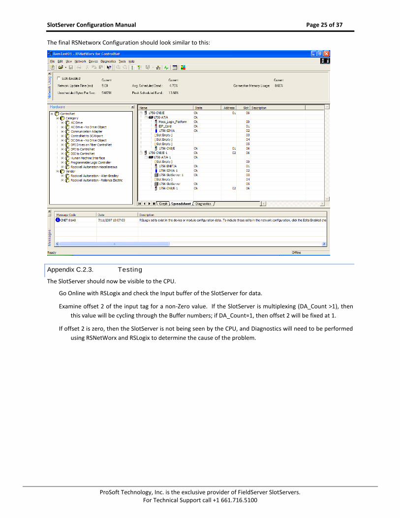
The final RSNetworx Configuration should look similar to this:
Appendix C.2.3. Testing
The SlotServer should now be visible to the CPU.
Go Online with RSLogix and check the Input buffer of the SlotServer for data.
Examine offset 2 of the input tag for a non-Zero value. If the SlotServer is multiplexing (DA_Count >1), then
this value will be cycling through the Buffer numbers; if DA_Count=1, then offset 2 will be fixed at 1.
If offset 2 is zero, then the SlotServer is not being seen by the CPU, and Diagnostics will need to be performed
using RSNetWorx and RSLogix to determine the cause of the problem.
SlotServer Configuration Manual Page 26 of 37
ProSoft Technology, Inc. is the exclusive provider of FieldServer SlotServers. For Technical Support call +1 661.716.5100
Appendix C.2.4. Connection limitations -Controll ing the SlotServer using ControlNet
Only one remote I/O rack is supported.
I/O can only be added online using a direct connection.
The following Vendor information provides clarification:
SlotServer Configuration Manual Page 27 of 37
ProSoft Technology, Inc. is the exclusive provider of FieldServer SlotServers. For Technical Support call +1 661.716.5100
Appendix C.3. Dealing with ControlLogix RPI Settings
When setting up the SlotServer for ControlLogix, it is necessary to select the Request Packet Interval (RPI). The RPI is the rate at which data is transferred to and from the SlotServer IO buffers. The following factors need to be considered when deciding on an RPI:
Minimum RPI setting for the SlotServer is 100ms.
The Scan_Interval parameter of the two Logix Map descriptors must be faster than the RPI to ensure smooth
communications and prevent timeouts.
The number of message blocks used does not affect the RPI setting, but will affect the effective update rate
for any one message block. The effective update rate for data to/from the SlotServer’s Data Arrays to the
Logix CPU tags is the scan interval of the block since data is updated to the block every scan interval.
Increasing the number of blocks will decrease the effective update rate per block. This update rate does
not include the time taken to obtain data from the third party network, which is dependant entirely on
the third party protocol involved.
The program scan rate should be set to run faster than the RPI. We recommend twice as fast. If the ladder
program scan is slower than the RPI rate, it would be possible to miss some blocks altogether. It is further
recommended that diagnostics be added to the ladder program to detect missed blocks
The effective update rate can be calculated using the following formula:
when using the full LonWorks Open Interface configuration.
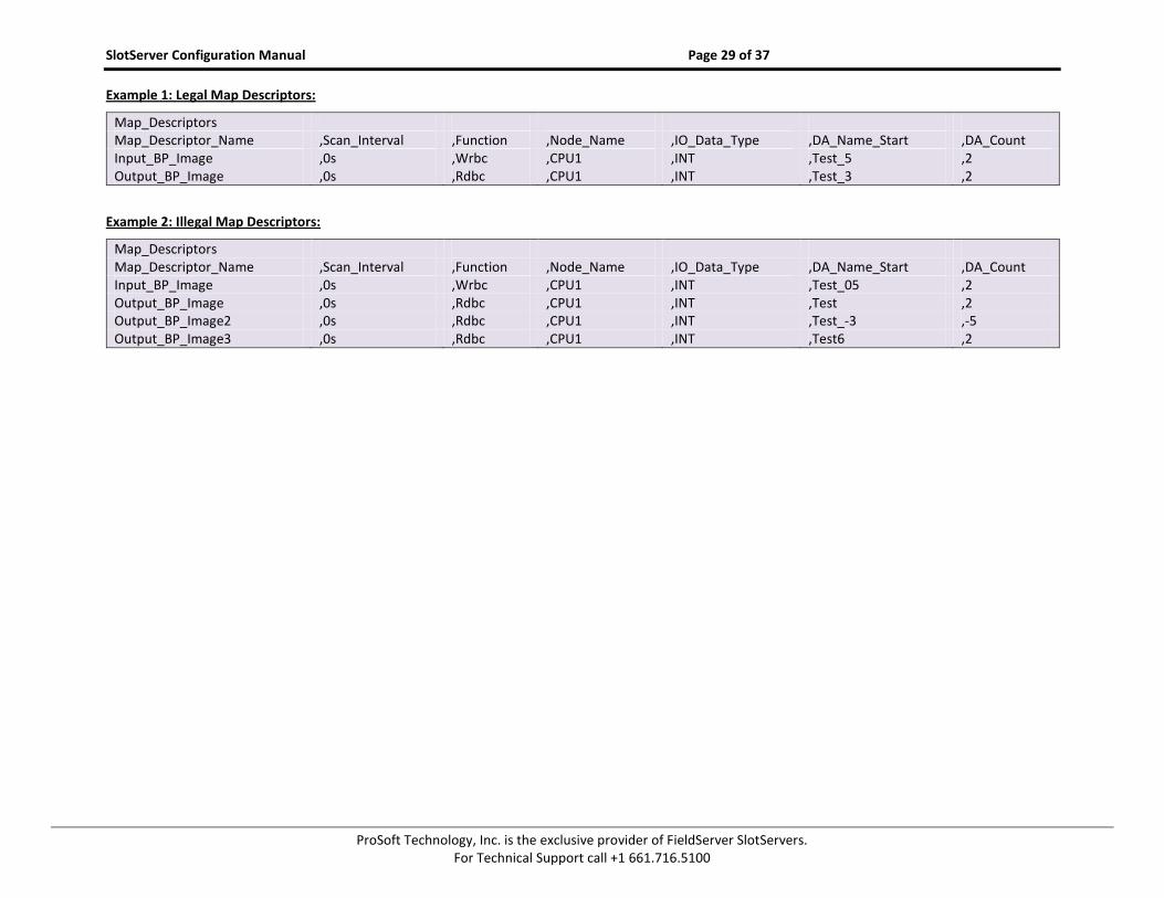
Appendix C.4. Rules for Naming Logix driver Data Arrays
The Logix driver attaches significance to the name of the Data Array used in the Logix Driver Map Descriptor. This allows the user to declare a series of Data Arrays to be multiplexed through the input and output buffers of the SlotServer. In general, Data Arrays would be named In_1 to In_x for input buffer arrays, and Out_1 to Out_y for output buffer arrays (where x and y are numbers reflecting the maximum input and output Array numbers respectively). For example, an application that multiplexes 6 Data Arrays worth of data through the Input buffer would use Data Arrays named In_1 through In_6. In this example, DA_Name_Start is declared as In_1, and DA_Count is declared as 6. If an alternative naming convention is required, the following restrictions apply:
The Data Array name must end in _x, where x is a positive integer number.
The total length of the Data Array name (including _x) must not exceed 15 characters.
No leading zeros should be used in the _x number (For example, use _5, not _05)
The “x” part of the _x in the data array name will be the number shown in offset 2 of the input buffer for the
purposes of de-multiplexing in the CPU.
There is only one Map Descriptor for linking Data Arrays to the input buffer (function Wrbc), and one for
linking Data Arrays to the output buffer (function Rdbc). It is therefore not possible to map non-
continuous Data Array number sequences. (For example, you can map numbers 5 through 25, but you
cannot map numbers 1 through 3, and then 5 through 8 at the same time).
6 a message block pair consists of an output and input block
SlotServer Configuration Manual Page 28 of 37
ProSoft Technology, Inc. is the exclusive provider of FieldServer SlotServers. For Technical Support call +1 661.716.5100
All Data Arrays (not just the start Data Array) must be declared individually in the Data Arrays Section.
The following examples describe legal and illegal naming conventions respectively:
SlotServer Configuration Manual Page 29 of 37
ProSoft Technology, Inc. is the exclusive provider of FieldServer SlotServers. For Technical Support call +1 661.716.5100
ProSoft Technology, Inc. is the exclusive provider of FieldServer SlotServers. For Technical Support call +1 661.716.5100
Appendix D. REFERENCE
Appendix D.1. Description of Data Transfer Process
The data connection from the SlotServer to the Logix CPU consists of 496 bytes of input and 496 bytes of output data. Of the 2 Map Descriptors specified, the one with the WRBC function writes data to the Logix CPU filling its input data, and the one with the RDBC function accepts the Logix CPU’s output data.
The Map Descriptor’s IO_Data_Type field organizes the 496 bytes into either Bytes (SINT), Words (INT) or Double Words (DINT or REAL) reducing the number of elements that can be transferred. Of the resulting number of elements, the first 4 are reserved for the IO image header (Refer to Appendix D.2).
The SlotServer acts as a multiplexer when it sends data to the Logix-CPU and as a demultiplexer when it receives data from the Logix-CPU.
The diagram on the next page describes the SlotServer operation methodology:
For input data, the input data from the external device is placed into the 25 Data Arrays numbered In_1 to In_25. The SlotServer sends the data from these Data Arrays over the IO image connection one at a time by placing the block number at offset 2 of the image header and the data from offset 4. The reverse happens at the Logix-CPU where a demultiplexer is implemented in Ladder to route the data to each of the 25 CPU Tags.
For output data, the Logix-CPU has to place the data and block number into the Output Image Tag and send it to the SlotServer. The SlotServer then demultiplexes the data by placing it into the appropriate Out_x Data Array depending on the block number specified in the IO image header.
SlotServer Configuration Manual Page 31 of 37
ProSoft Technology, Inc. is the exclusive provider of FieldServer SlotServers. For Technical Support call +1 661.716.5100
Local:Slot:I:Data
Local:Slot:O:Data
Input Data Image
Controller Tag
Output Data Image
Controller Tag
Logix CPU
Input Data
Multiplexer
Output Data
DeMultiplexer
SlotServerInput Data
In [24]
Out [24]
Out [0]
External Device
eg. LonWorks
Modbus
0
1
2
3
4
...
79
Protocol Type
Node Status
Data Block Number
Reserved
In_x
Data
Out_x
Data
Offset Description
SlotServer Data Transfer over IO Data Image
In [1]
Offset Description
In [0]
0
1
2
3
4
...
79
Protocol Type
Node Status
Data Block Number
Reserved
Output Data
Out [1]
In_1
In_2
In_3
In_4
..
In_25
Out_1
Out_2
Out_3
Out_4
..
Out_25
SlotServer Configuration Manual Page 32 of 37
ProSoft Technology, Inc. is the exclusive provider of FieldServer SlotServers. For Technical Support call +1 661.716.5100
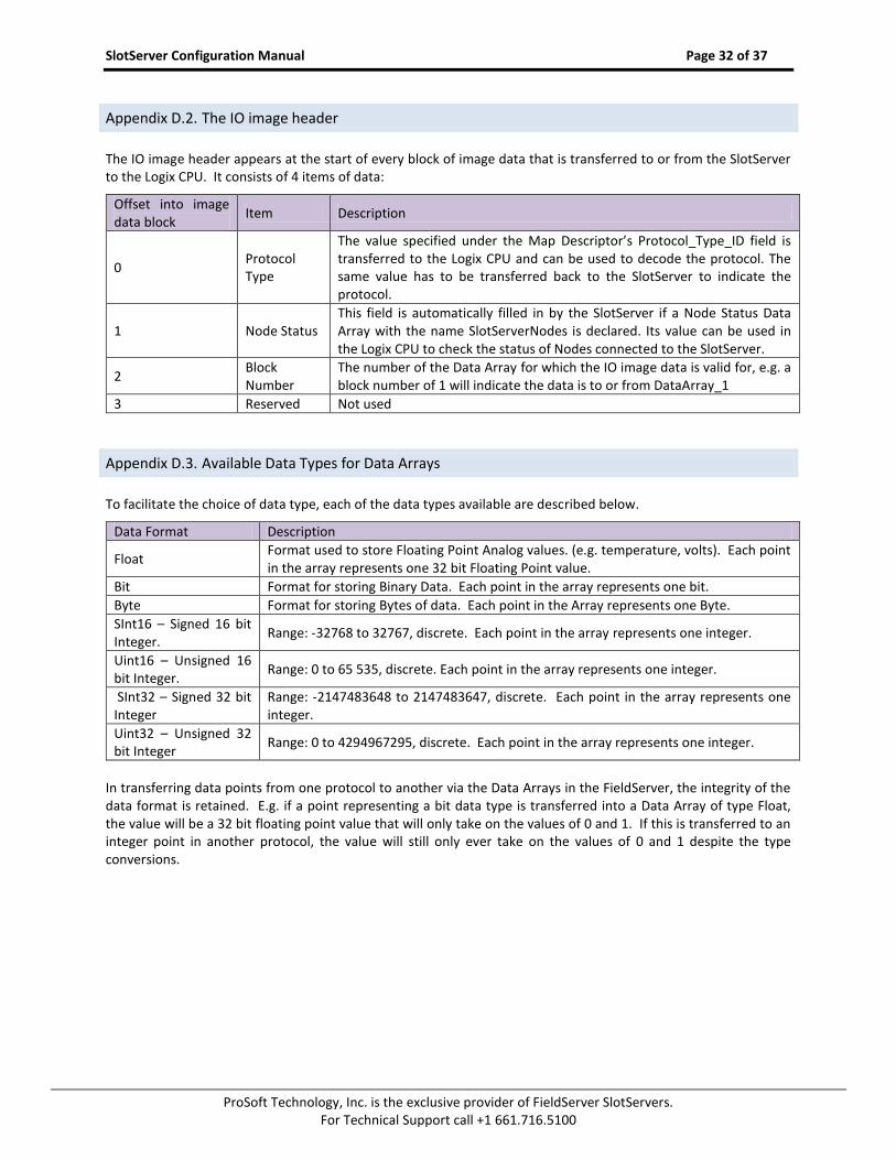
Appendix D.2. The IO image header
The IO image header appears at the start of every block of image data that is transferred to or from the SlotServer to the Logix CPU. It consists of 4 items of data:
Offset into image data block
Item Description
0 Protocol Type
The value specified under the Map Descriptor’s Protocol_Type_ID field is transferred to the Logix CPU and can be used to decode the protocol. The same value has to be transferred back to the SlotServer to indicate the protocol.
1 Node Status This field is automatically filled in by the SlotServer if a Node Status Data Array with the name SlotServerNodes is declared. Its value can be used in the Logix CPU to check the status of Nodes connected to the SlotServer.
2 Block Number
The number of the Data Array for which the IO image data is valid for, e.g. a block number of 1 will indicate the data is to or from DataArray_1
3 Reserved Not used
Appendix D.3. Available Data Types for Data Arrays
To facilitate the choice of data type, each of the data types available are described below.
Data Format Description
Float Format used to store Floating Point Analog values. (e.g. temperature, volts). Each point in the array represents one 32 bit Floating Point value.
Bit Format for storing Binary Data. Each point in the array represents one bit.
Byte Format for storing Bytes of data. Each point in the Array represents one Byte.
SInt16 – Signed 16 bit Integer.
Range: -32768 to 32767, discrete. Each point in the array represents one integer.
Uint16 – Unsigned 16 bit Integer.
Range: 0 to 65 535, discrete. Each point in the array represents one integer.
SInt32 – Signed 32 bit Integer
Range: -2147483648 to 2147483647, discrete. Each point in the array represents one integer.
Uint32 – Unsigned 32 bit Integer
Range: 0 to 4294967295, discrete. Each point in the array represents one integer.
In transferring data points from one protocol to another via the Data Arrays in the FieldServer, the integrity of the data format is retained. E.g. if a point representing a bit data type is transferred into a Data Array of type Float, the value will be a 32 bit floating point value that will only take on the values of 0 and 1. If this is transferred to an integer point in another protocol, the value will still only ever take on the values of 0 and 1 despite the type conversions.
SlotServer Configuration Manual Page 33 of 37
ProSoft Technology, Inc. is the exclusive provider of FieldServer SlotServers. For Technical Support call +1 661.716.5100
Appendix D.4. Permissible Values for Configuration File Variables
Default and acceptable values for the different variables defined in the configuration file. Default values are indicated in bold. Timing parameters are listed in seconds (0.003 would represent three milliseconds)
While this list contains acceptable variables for the FieldServer, some are not suitable for all configurations, depending on the drivers used. Please see the Driver Manual for complete information regarding acceptable variable values for specific drivers.
Note: Titles in brackets indicate aliases
Appendix D.4.1. Common Information
Section Title
FieldServer
Column Title Function Legal Values
Title Allows user to add title to main menu if desired. Title text may not contain spaces
Title Text
Cache_Age; (Cache_Age_Timeout)
When poll block caching is used, data previously polled and stored in an internal data buffer is returned to the Server, providing the data is not too old. This parameter specifies the length of time cached data is valid.
Time in seconds, 300s
Cache_Size* Specify size of Cache 0-1000; 80
Cache_Time_To_Live
Used for Port Expansion. A cache is created for data from a Node for which no Map Descriptor is configured. If this data is not accessed for longer that the time specified by this parameter, the cache will be cleared.
Time in seconds, 300s
Appendix D.4.2. Data Arrays
Section Title
Data_Arrays
Column Title Function Legal Values
Data_Array_Name (DA_Name)
Provides name for Data Array Up to 15 Alpha Numeric Characters
Data_Format Provides Data Format
Bit, Uint16, Sint16, Uint32, Sint32 or BYTE; Specifies size of source value when scaling Float; specifies floating point format for preloaded data in buffer.
Data_Array_Length (Buffer_Length)
Number of Data Objects 0-10000
Data_Array_Function* Special function for the Data Array Refer to table in 0, None
DA_Function_After_Store
If this parameter is specified, when a value different to the current value is written to the Data Array it will be stored in the SlotServer’s Non-Volatile Memory. On start-up this value is loaded from the Non-Volatile Memory into the Data Array. This value is stored 3 times a minute, so if more writes than that are done, the values will be stored in the
Non-Volatile, -
SlotServer Configuration Manual Page 34 of 37
ProSoft Technology, Inc. is the exclusive provider of FieldServer SlotServers. For Technical Support call +1 661.716.5100
Data Array, but not to the Non-Volatile Memory. Storing this value has performance impacts, so care must be taken to store this value only if needed. Refer to Section 5.3
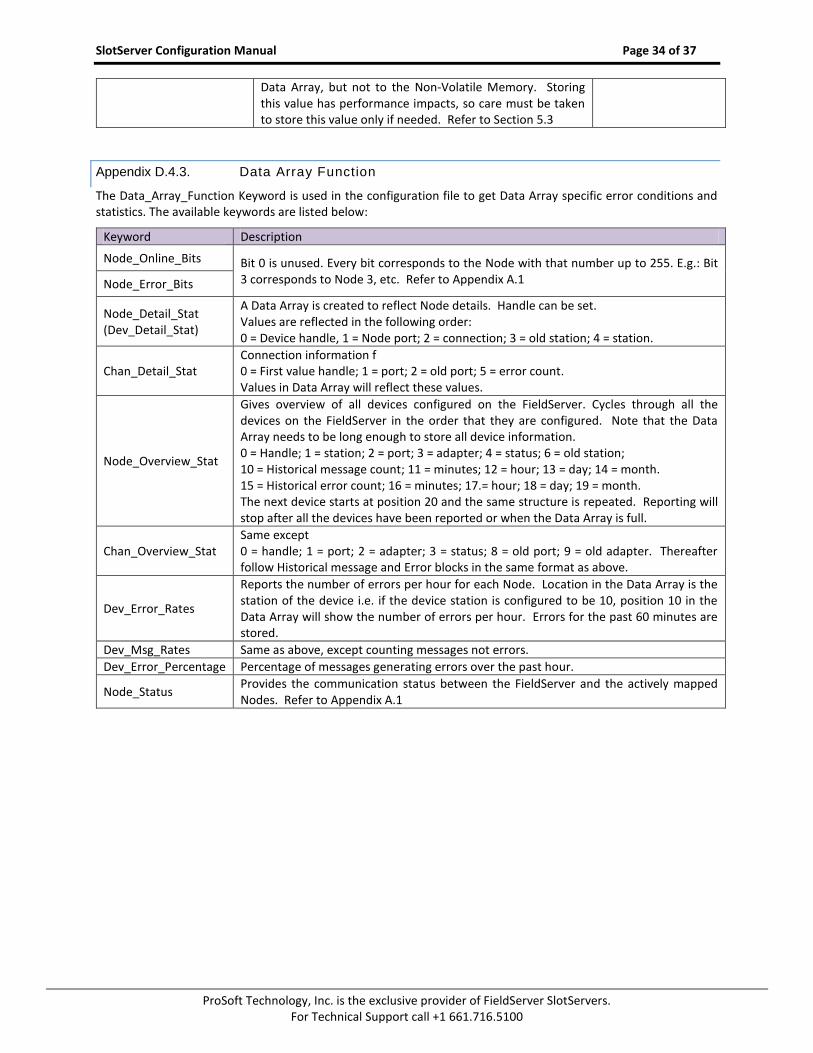
Appendix D.4.3. Data Array Function
The Data_Array_Function Keyword is used in the configuration file to get Data Array specific error conditions and statistics. The available keywords are listed below:
Keyword Description
Node_Online_Bits Bit 0 is unused. Every bit corresponds to the Node with that number up to 255. E.g.: Bit 3 corresponds to Node 3, etc. Refer to Appendix A.1 Node_Error_Bits
Node_Detail_Stat (Dev_Detail_Stat)
A Data Array is created to reflect Node details. Handle can be set. Values are reflected in the following order: 0 = Device handle, 1 = Node port; 2 = connection; 3 = old station; 4 = station.
Chan_Detail_Stat Connection information f 0 = First value handle; 1 = port; 2 = old port; 5 = error count. Values in Data Array will reflect these values.
Node_Overview_Stat
Gives overview of all devices configured on the FieldServer. Cycles through all the devices on the FieldServer in the order that they are configured. Note that the Data Array needs to be long enough to store all device information. 0 = Handle; 1 = station; 2 = port; 3 = adapter; 4 = status; 6 = old station; 10 = Historical message count; 11 = minutes; 12 = hour; 13 = day; 14 = month. 15 = Historical error count; 16 = minutes; 17.= hour; 18 = day; 19 = month. The next device starts at position 20 and the same structure is repeated. Reporting will stop after all the devices have been reported or when the Data Array is full.
Chan_Overview_Stat Same except 0 = handle; 1 = port; 2 = adapter; 3 = status; 8 = old port; 9 = old adapter. Thereafter follow Historical message and Error blocks in the same format as above.
Dev_Error_Rates
Reports the number of errors per hour for each Node. Location in the Data Array is the station of the device i.e. if the device station is configured to be 10, position 10 in the Data Array will show the number of errors per hour. Errors for the past 60 minutes are stored.
Dev_Msg_Rates Same as above, except counting messages not errors.
Dev_Error_Percentage Percentage of messages generating errors over the past hour.
Node_Status Provides the communication status between the FieldServer and the actively mapped Nodes. Refer to Appendix A.1
SlotServer Configuration Manual Page 35 of 37
ProSoft Technology, Inc. is the exclusive provider of FieldServer SlotServers. For Technical Support call +1 661.716.5100
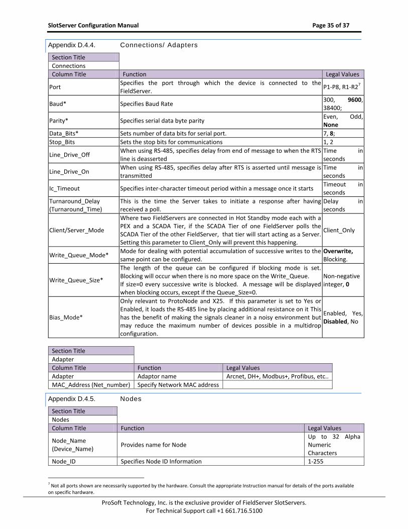
Appendix D.4.4. Connections/ Adapters
Section Title
Connections
Column Title Function Legal Values
Port Specifies the port through which the device is connected to the FieldServer.
P1-P8, R1-R27
Baud* Specifies Baud Rate 300, 9600, 38400;
Parity* Specifies serial data byte parity Even, Odd, None
Data_Bits* Sets number of data bits for serial port. 7, 8;
Stop_Bits Sets the stop bits for communications 1, 2
Line_Drive_Off When using RS-485, specifies delay from end of message to when the RTS line is deasserted
Time in seconds
Line_Drive_On When using RS-485, specifies delay after RTS is asserted until message is transmitted
Time in seconds
Ic_Timeout Specifies inter-character timeout period within a message once it starts Timeout in seconds
Turnaround_Delay (Turnaround_Time)
This is the time the Server takes to initiate a response after having received a poll.
Delay in seconds
Client/Server_Mode
Where two FieldServers are connected in Hot Standby mode each with a PEX and a SCADA Tier, if the SCADA Tier of one FieldServer polls the SCADA Tier of the other FieldServer, that tier will start acting as a Server. Setting this parameter to Client_Only will prevent this happening.
Client_Only
Write_Queue_Mode* Mode for dealing with potential accumulation of successive writes to the same point can be configured.
Overwrite, Blocking.
Write_Queue_Size*
The length of the queue can be configured if blocking mode is set. Blocking will occur when there is no more space on the Write_Queue. If size=0 every successive write is blocked. A message will be displayed when blocking occurs, except if the Queue_Size=0.
Non-negative integer, 0
Bias_Mode*
Only relevant to ProtoNode and X25. If this parameter is set to Yes or Enabled, it loads the RS-485 line by placing additional resistance on it This has the benefit of making the signals cleaner in a noisy environment but may reduce the maximum number of devices possible in a multidrop configuration.
Enabled, Yes, Disabled, No
Section Title
Adapter
Column Title Function Legal Values
Adapter Adaptor name Arcnet, DH+, Modbus+, Profibus, etc..
MAC_Address (Net_number) Specify Network MAC address
Appendix D.4.5. Nodes
Section Title
Nodes
Column Title Function Legal Values
Node_Name (Device_Name)
Provides name for Node Up to 32 Alpha Numeric Characters
Node_ID Specifies Node ID Information 1-255
7 Not all ports shown are necessarily supported by the hardware. Consult the appropriate Instruction manual for details of the ports available on specific hardware.
SlotServer Configuration Manual Page 36 of 37
ProSoft Technology, Inc. is the exclusive provider of FieldServer SlotServers. For Technical Support call +1 661.716.5100
Section Title
Nodes
Column Title Function Legal Values
Protocol Specifies Protocol used Modbus/TCP etc..
IP_Address IP address of Client PLC Valid IP address
Retries
Specifies how many sequential errors must occur before marking a data buffer and poll block bad, and marking a device offline. The FieldServer will poll the device and if it receives no response will retry polling the device the number of times specified by the retries parameter. The FieldServer will attempt to recover the connection once the recovery interval has elapsed
Count Default 3
Retry_Interval Interval between retries Interval in Seconds
Srv_Offline_Method
A Server Node could send contradictory information if its data comes from multiple Client Nodes, some of which are offline and others online, causing it to respond differently depending on what data is polled. This confuses some systems. This setting allows the user to select whether the Server Node should appear online or offline if there is a mix of Client Node Statuses. Ignore_Clients - causes the Server to behave explicitly – not to depend on the status of the Client Node, but on the data validity only. i.e. non-expired data will be served whether or not the responsible Client Nodes are online. Any_Offline - suppress a data response if ANY of the responsible Client Nodes for the data range concerned are offline All_Offline - only suppress a data response if ALL of the responsible Client Nodes for the data range concerned are offline. Always_Respond overrides the data validity as well. i.e. it forces the Server Node to regard data as valid even if the Client Node is offline or the data has expired.
Ack_Complete (default) - the Server waits for the Client Side write transaction to complete before acknowledging the Write request. This makes for good reliability but has a cost in terms of throughput. Ack_Immediate - fast, but less reliable. The Server immediately acknowledges a Write request before queuing the Client Side Write. The acknowledgement is thus not affected by the success or failure of the Client Side Write. Only recommended if the same points are updated regularly. Ack_Verified - most reliable, and slowest. The Server waits for a Client Side Write and Readback to be completed, and only updates the data value if a data comparison between the Client Side Write and Read values passes. If the transaction fails for any reason or if the data comparison fails, the Server responds with a negative acknowledgement.
Ack_Complete, Ack_Immediate, Ack_Verified
Enable_Write_Retries
The default write behavior is for a write operation (WRB or WRBX) to be attempted once only. If a timeout occurs the write operation is aborted. If set to yes, this parameter enables failed write requests to be retried. The number and timing of the write retries is then governed by the Retries and Retry_Interval parameters. Warning: ensure that repeated writes are safe for your application since a Write may be retried because of a transmission error in the Write acknowledgement, in which case the remote device will see two similar write requests.
Yes, No
SlotServer Configuration Manual Page 37 of 37
ProSoft Technology, Inc. is the exclusive provider of FieldServer SlotServers. For Technical Support call +1 661.716.5100
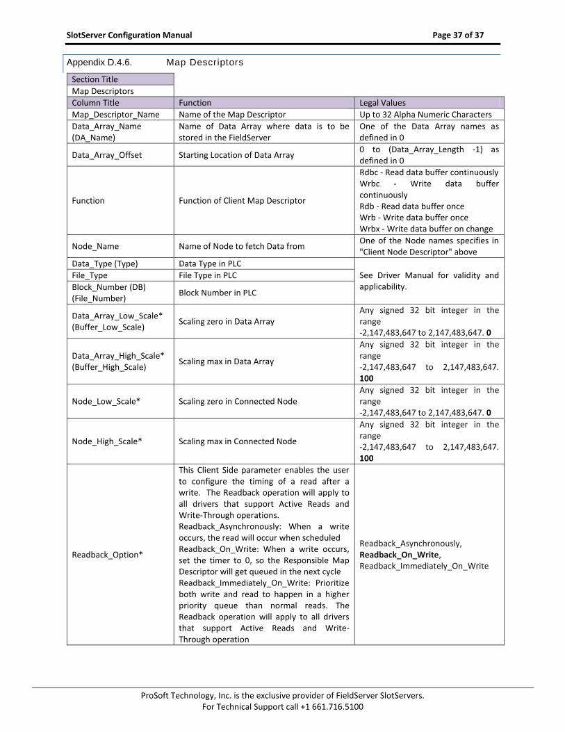
Appendix D.4.6. Map Descriptors
Section Title
Map Descriptors
Column Title Function Legal Values
Map_Descriptor_Name Name of the Map Descriptor Up to 32 Alpha Numeric Characters
Data_Array_Name (DA_Name)
Name of Data Array where data is to be stored in the FieldServer
One of the Data Array names as defined in 0
Data_Array_Offset Starting Location of Data Array 0 to (Data_Array_Length -1) as defined in 0
Function Function of Client Map Descriptor
Rdbc - Read data buffer continuously Wrbc - Write data buffer continuously Rdb - Read data buffer once Wrb - Write data buffer once Wrbx - Write data buffer on change
Node_Name Name of Node to fetch Data from One of the Node names specifies in "Client Node Descriptor" above
Data_Type (Type) Data Type in PLC
See Driver Manual for validity and applicability.
File_Type File Type in PLC
Block_Number (DB) (File_Number)
Block Number in PLC
Data_Array_Low_Scale* (Buffer_Low_Scale)
Scaling zero in Data Array Any signed 32 bit integer in the range -2,147,483,647 to 2,147,483,647. 0
Data_Array_High_Scale* (Buffer_High_Scale)
Scaling max in Data Array
Any signed 32 bit integer in the range -2,147,483,647 to 2,147,483,647. 100
Node_Low_Scale* Scaling zero in Connected Node Any signed 32 bit integer in the range -2,147,483,647 to 2,147,483,647. 0
Node_High_Scale* Scaling max in Connected Node
Any signed 32 bit integer in the range -2,147,483,647 to 2,147,483,647. 100
Readback_Option*
This Client Side parameter enables the user to configure the timing of a read after a write. The Readback operation will apply to all drivers that support Active Reads and Write-Through operations. Readback_Asynchronously: When a write occurs, the read will occur when scheduled Readback_On_Write: When a write occurs, set the timer to 0, so the Responsible Map Descriptor will get queued in the next cycle Readback_Immediately_On_Write: Prioritize both write and read to happen in a higher priority queue than normal reads. The Readback operation will apply to all drivers that support Active Reads and Write-Through operation