Page 1
Smart Sifter Vertical Shaft & Splined Coupler
Replacement Manual
Company: Norvell Company Inc. Phone: 800-653-3147
Fax: 620-223-3115
Date: Sept. 2014, Rev. #2
This manual is for our customers who wish to replace their existing 2.19” diameter
vertical shafts and are replacing the existing splined couplers (spring of 2011 design)
with the new SS-250-14 splined coupler design introduced in March of 2012. These
instructions apply to our Smart Sifter units that use a Lafert motor and drive components.
Before beginning:
Check your shipping container and make sure you have everything per the packing list
attached to the outside of the container. Please contact our office right away if there are
any discrepancies.
Items you will need:
3 foot level Scouring pad
Dead blow hammer Flat head screwdriver
A board to use as a lever (step 17) ¼” thick shim (step 17)
2 small pry bars Red #262 Loctite
Green #680 Loctite Small telescopic magnet
Hex bit socket set (US) Box & open end wrench set (US)
½” Ratchet & deep-well socket set (US) 3/8” Ratchet & socket set (US)
½” foot/pound Torque wrench ¼” inch/pound Torque wrench
¼” Ratchet & socket set (US) 3/8” to ½” adapter
27/64 cobalt drill bit Electric drill
Hammer and center punch
Ratchet straps (to support shaft/weight bucket assembly during removal and installation)
Straight needlepoint coupler for grease gun (McMaster-Carr P/N 2906K92 or
equivalent)
White “Krylon” paint (only if using existing coverplates)
Page 2
Getting started:
1) Turn off the power to the sifter unit, and use standard tag/lockout procedures to
ensure that no electrical power is available to the sifter while the repair work is being
done. Do not start this procedure until you are certain the power is disconnected.
2) Clear an area near the sifter to have a place for all the parts that will be removed from
the sifter. You may want to place the items on a pallet if you have access to a forklift
or pallet jack in the sifter area. Note: the replacement parts will be shipped to you on
a pallet or large wooden box via common carrier (LTL). If a forklift or pallet jack is
not available in the sifter area, the new parts will have to be taken off the pallet and
moved to the sifter area prior to beginning the shaft replacement.
3) Remove the (8) 5/16-18 bolts that attach each of the steel vertical guards to the side
channels, and remove the guards from both sides of the sifter. If your sifter has the
aluminum guards, there are (2) 5/16-18 bolts per panel that will need to be removed.
4) Loosen the (4) adjustment nuts on the back side of the motor mount baseplate, and
slide the motor as far to the left as it will go. Remove the drive belts from the motor
sheave. Then slide motor and motor mount assembly as far to the right as possible.
5) Loosen the hose clamps that attach the horizontal shaft guard to the “snout” on the
right angle gearboxes. Slide the two halves of the guard together in the middle of the
shaft to allow access to the horizontal couplers. Loosen the torx screws on the
couplers, and insert a large flat blade screwdriver between the two halves of the
coupler and give it a tap with a small hammer. The couplers will easily spread apart
and slide away from the ends of the 1” diameter horizontal shaft (they are sealed to
the shaft with Loctite #680). Slide the couplers over onto the 1” diameter shaft and
remove the horizontal shaft, couplers, and guard assembly from below the sifter.
6) Remove the cover plates (item #4 on Isometric drawings), hex bolts, & washers (item
#12, 13 &14) from the front of the L.H. & R.H. box plates (item #2 & 3) on both
sides of the sifter drive. Place a jack or other form of support below the gearbox.
Remove the four horizontal bolts & nuts (item #11, 13 & 15). Loosen vertical bolts
&/or nuts (item #6 thru 10) that attach L.H. & R.H. box plates to lower side channels
just enough to let them move. Slide box plates away from gearboxes on each side.
Lower the gearboxes away from the sifter. Make sure you mark the gearbox that is on
the motor side (a letter M with a Sharpie will do) so it can be placed back into the
correct position when the sifter is re-assembled. Once the gearboxes are clear of the
Page 3
sifter, you can loosen the bolts on the splined vertical coupler and remove the old
couplers and the keys from the gearbox assemblies. DO NOT LOSE THE KEYS.
7) To remove the counterweights from the weight buckets, you will need to remove the
bolts that hold the small stainless steel cover plate that is over the loading slot at the
top of the weight bucket (some sifters do not have these cover plates). Use the pry bar
to get underneath the first counterweight, and slide it upward until it reaches the
loading slot at the top of the weight bucket, then slide it out through the slot. Continue
this process using the small pry bars until all of the counterweights have been
removed. There will be an equal number of weights on each side, but it would be a
good idea to keep the counterweights from each side separate, so they can be installed
back into the same weight buckets that they were removed from. Count them as well
and note the quantities for each weight bucket in your Smart Sifter files for reference
later at step #29.
8) On sifters built after April 2004, remove the ¼-20 bolts that hold the small plastic cap
guard over the upper pillow block bearings on both upper side channels, and remove
the guards. You will re-use these guards and fasteners, so put them where you can
find them later. There are (2) hex head set screws at the collar at the top of the
Rexnord pillow block bearing that mounts to the UPPER side channel. These tighten
against the vertical shaft. BEFORE YOU GO ANY FURTHER, YOU MUST
MAKE ABSOLUTELY SURE THAT THE BEARING SET SCREWS ARE
TIGHTENED PROPERLY AGAINST THE VERTICAL SHAFTS ON BOTH
SIDES OF THE SIFTER! Please do NOT ignore this step. Once you remove the
bottom bearing bolts, the weight of the empty weight bucket and the vertical shafts
will be entirely supported by these set screws. If the vertical shaft/weight bucket
assembly slips out of the upper bearing during this operation, serious personal
injury and/or damage to the sifter could result.
9) Before the vertical shaft/weight bucket/bearing assemblies can be removed from both
sides of the sifter, you must support each shaft assembly so that it cannot fall from the
sifter. You can use a lifting strap and hoist, ratchet straps, forklift, or some other form
of support. The assembly is heavy, and it MUST BE SUPPORTED PROPERLY
BEFORE REMOVING THE BEARING BOLTS. Also, this is a good time to
measure the clearance dimension between the bottom of the driven sheave and the top
of the lower side channel. You will want to write this down and use it again to set the
sheave height when you install the motor side vertical shaft assembly.
10) Once you have the supports in place, remove the (2) 5/8-11 bolts that hold the
Rexnord pillow-block bearing to the lower side channel. Then remove the (2) 5/8-11
Page 4
bolts from the Rexnord bearing on the upper side channel. Using your support
straps, carefully move the vertical shaft assemblies away from the sifter. Note that
the drive belts may come off when you swing out the shaft on the motor side. This is
normal. Just make sure you put them back into place BEFORE you tighten the
bearings back onto the “motor side” side channels!
11) Place the shaft assemblies on a flat working surface and loosen the set screws for the
bearing collars and the weight bucket mounting collars. You can also remove the
driven sheave and bushing on the motor side shaft. Remove the pillow block
bearings and the sheave/bushing assembly. Using a scouring pad, carefully clean any
rusty or tarnished areas on the surface of the vertical shafts. Drive the existing
vertical shafts out of the weight bucket mounting collars from the top. A large dead-
blow hammer should be used. Do not damage the outer edge of the ends of the
shafts. Burrs or swelled edges on the shaft ends will damage the inside diameter of
the collars on the weight buckets as the shafts are driven through them. Do not
damage the weight bucket collars with the shaft or the hammer. Use another smaller
diameter piece of shaft as a drift to drive them out if necessary.
Re-assembly:
12) Review the vertical shaft assembly drawings provided for the motor and non-motor
side of the sifter, and lay out all the new and existing parts required to assemble
them. Starting with the non-motor side, slip the shaft that does NOT have a keyway
for the driven sheave on it through the weight bucket, feeding the top of the shaft up
through the lower collar. Continue pushing the shaft upward through the upper collar
until the shaft extends 4.46” above the top of the weight bucket. Install the upper and
lower pillow block bearings with the collar on the top in the locations shown on the
drawing. Note! You must set the height of the bottom bearing 1.469” from the
bottom of the shaft to the bottom of the bearing as shown on the shaft assembly
drawings. This dimension is critical to make sure the couplers and gearbox are
installed at the correct height. Snug the set screws on the bearings and the weight
bucket just enough to keep them from sliding on the shaft while being bolted to the
side channels. Place the 3/8” key into the keyway on the 1.75” diameter section at
the bottom of the vertical shaft. Slide the top coupler (female) up the 1.75” shaft
until it bottoms out against the step on the vertical shaft. You may have to loosen the
set screws to get the top coupler to slide onto the vertical shaft. Notice that a short
section of the top coupler must go inside the bearing. There will be approximately
1/16” clearance between the bottom of the bearing and the shoulder of the top
coupler if it is installed correctly. Remove the top coupler Torx head screws, place
262 Loctite on them, re-install them into the coupler, and tighten them to 168 in/lbs.
Page 5
(14 ft/lbs.) while holding the top coupler tightly against the shoulder on the vertical
shaft.
13) Repeat the previous step on the motor side, but before you install the lower bearing,
place the existing ½” wide key into the shaft keyway and slide the bushing & driven
3VX sheave onto the shaft below the weight bucket as shown. See drawing “Plan
view – fastener location at 3VX sheave & bushing” for details of the bushing
fasteners and the direction of the weight bucket. If necessary, loosen the set screws
and turn the weight bucket on the shaft until the sheave bushing mounting bolts are
in the correct location to clear the weight bucket as shown on the drawing. Then
snug up the set screws on the weight bucket again. Once the bushing and sheave is
in place, you can install the upper & lower bearing on the motor side shaft. See
underlined note above for information regarding how & where to position the lower
bearing. Then install the top coupler to the bottom of the vertical shaft and tighten in
place as described above.
Page 9
14) Attach the lift straps to the upper half of the non-motor side vertical shaft assembly
and raise it into position at the side of the sifter. Check the vertical shaft assembly
one last time to make sure all the components are assembled per the drawings. Move
the shaft into position, placing the splined coupler end into the milled slot in the
alignment tool, and pushing the shaft and bearings all the way back against the
bearing mounts on the side channels. Install the 5/8-11 bolts through the top and
bottom bearings and into the side channels, but do not torque them at this time, just
hand tighten them.
15) Now you must center the shaft on the sifter. Start with the lower bearing. The bolts
must be just loose enough to let the bearing move. Place the end of a tape measure
against the shaft just above the bearing collar, and measure the distance horizontally
to the outside edge of the sifter box. Then do the same on the opposite side of the
shaft. Add the two measurements together and divide by 2. Then slide the bearing
and shaft assembly to one side or the other until the distance is the same on both
sides of the shaft. Tighten the bolts for the bottom bearing to 20 ft/lbs., and then
repeat this procedure at the top bearing. Once the shaft assembly is centered in on
the box, tighten the top bearing bolts to 20 ft/lbs. and check the measurements one
last time. If they are the same, torque all four bearing mounting bolts to 70 ft/lbs.,
and then to a final torque of 90 ft/lbs. See included drawing for example of how to
measure this.
16) Pull one set screw at a time out of the bearing collars, apply 262 Loctite, and re-
install the set screw. Repeat this until all four set screws are tightened to 50 ft/lbs.
17) Now you can set the correct distance between the top of the weight bucket and the
bottom of the upper side channel. Turn the weight bucket & vertical shaft so that it is
facing toward the side of the sifter box (under the side channel). Slip a board in
between the top of the bottom side channel and the bottom of the weight bucket. Use
this board as a lever to raise and lower the bucket while setting the clearance. Make
a 0.25” thick shim to place on top of the weight bucket. While supporting the bottom
of the bucket with the board, loosen the set screws on the weight bucket mounting
collars and lower the bucket until the 0.25” thick shim can be placed between the top
of the weight bucket and the bottom of the upper side channel. Then raise the board
and the weight bucket until the shim is held tightly between the weight bucket and
side channel. Tighten the top weight bucket set screw enough to hold the weight
bucket in place on the vertical shaft. Then remove the 0.25” shim. Remove the other
three weight bucket set screws one at a time. Place the 27/64” diameter drill bit into
the electric drill, place the drill bit inside a set screw hole in the collar, and carefully
drill a small dimple into the shaft (max. 0.13” deep) for the setscrew. Clean the
Page 10
metal shavings out the hole with air &/or the small telescopic magnet. Take care to
keep the shavings away from the pillow block bearing. Cover the bearing if
necessary. Once the hole is clean, place 262 Loctite onto the set screw threads and
tighten to 30 ft/lbs. Repeat this procedure with all four of the set screw holes on the
non-motor side weight bucket collars. Then tighten the setscrews to a final torque of
50 ft./lbs.
18) On the motor side of the sifter, check the drawing dimensions and make sure that the
driven sheave and bushing are mounted high enough to clear the top of the lower
side channel when lifting the motor side vertical shaft assembly into position on the
side channels. SLIP THE DRIVE BELTS OVER THE MOTOR-SIDE
VERTICAL SHAFT ASSEMBLY AT THIS TIME AND TIE THEM OFF TO
THE SHAFT. FAILURE TO DO THIS WILL RESULT IN REPEATING THE
SHAFT ALIGNMENT PROCESS A 2ND
TIME. Repeat step #14 through #17 on
the motor side vertical shaft assembly. Once you have the motor-side vertical shaft
assembly centered and tightened in place, you can use the dimension you wrote
down in step #9 to set the height of the driven sheave and bushing.
19) Take the gearbox from the motor side (the one you marked “M” in step #6) and slide
the new SS-250-14 male splined coupler and the existing key all the way down until
it bottoms out on the vertical shaft of the gearbox. Be careful not to damage or
loosen the seal. You may have to loosen the set screws to get the coupler to slide
onto the gearbox shaft. Remove the coupler Torx head screws, place 262 Loctite on
them, re-install them into the coupler, and tighten them to 168 in/lbs. (14 ft/lbs.).
Then take the rubber spacer, center it on top of the coupler, and attach it to the
coupler with a small amount of adhesive (see the “Male splined coupler installation
detail” drawing). Repeat this procedure with the gearbox from the non-motor side of
the sifter. Our current gearbox design has an elongated horizontal “snout” that is to
be pointed toward the center of the sifter.
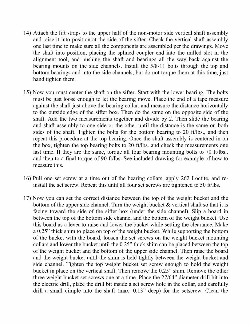
20) Review the “Splined Coupler/Shaft/Gearbox installation detail #1 & 2” drawings.
Place a bead of grease all the way around the top of the male splined coupler on each
gearbox. Also, brush a very thin film of grease onto each spline. Be careful here, as
too much grease will make it difficult to slide the male coupler into the female
coupler due to the tight tolerances they are manufactured with. You will add more
grease later through the grease zerk on the side of the top vertical coupler. Move the
motor-side gearbox below the motor-side vertical shaft assembly. Lift the gearbox
and coupler (marked “M”) up until the male coupler engages the splines in the
bottom of the motor side top vertical coupler. Then, using a jack or other form of
support, push it all the way up into the top coupler until the rubber spacer is seated
Page 11
against the end of the shaft. Make sure the rubber “V-seal” at the bottom of the
gearbox coupler slips inside the recess in the bottom of the top vertical coupler. This
may require you to work your way around the seal, pushing the lip up into the
opening as you go. Be careful not to damage the seal or force it off of the male
splined coupler. The gearbox/coupler assembly must be held snug against the
vertical shaft (but not enough to crush the rubber spacer) while installing the
boxplates. Do not let it slip down, or the horizontal shaft below the sifter will be
misaligned when you try to install it. Take some time to study the exploded
isometric drawings of the new gearbox mounting layout. Slide the motor side L.H. &
R.H. boxplates over against the sides of the gearbox. Take four 5/16-18 x 6” long
bolts, washers, and ESNA nuts (items 11,13, & 15) and install them horizontally
through the L.H. boxplate, with (2) over the gearbox, and (2) below the gearbox as
shown on the exploded isometric drawing. Tighten the 5/16-18 x 6” bolts to 15
ft/lbs. Remove the (3) 3/8-16 x 1.25” long vertical bolts one at a time, putting #262
Loctite on each one, and re-install them (Note: Loctite is not required on the bolt
assemblies using “ESNA” nuts). Tighten all of the 3/8-16 vertical bolts to 25 ft/lbs.
at the front and the back of the boxplates, and then remove the jack. Repeat this
procedure on the non-motor side of the sifter so that both gearbox & coupler
assemblies are in place.
Page 15
21) Remove the couplers from the 1” diameter horizontal shaft and clean the residue
from the #680 Loctite off of the shaft and the couplers. Once cleaned, slip the
couplers all the way onto the horizontal shaft. Position the horizontal shaft, the PVC
guards, and the horizontal couplers up under the sifter. Slide the 2 halves of the
guard together to make room to tighten the horizontal couplers. Slide the couplers
back onto the horizontal shaft until the edge of the coupler is flush with the ends of
the shaft. Lift the shaft up into position between the gearboxes, and slide the
couplers out onto the gearbox shafts at each end. Center one coupler between the
gearbox and the horizontal shaft, leaving a slight gap (1/8” max.) between the end of
the gearbox and the end of the horizontal shaft. Tighten the fasteners on that coupler
to 10 ft/lbs. Center the coupler onto the gearbox and the horizontal shaft at the
opposite end of the sifter. Snug one bolt up on the horizontal shaft side of the
coupler only. The coupler must be loose enough to allow the gearbox shaft to rotate
so that the weight buckets can be brought into alignment.
22) This step is very important to the operation of the sifter. THE WEIGHT
BUCKETS MUST BE ALIGNED CORRECTLY TO OPERATE AT
OPTIMUM EFFICIENCY. This can be accomplished by using a top view of the
sifter as your reference point, with the sifter door toward you (0 degrees) and the
weight buckets to the left and the right. Since the weight buckets rotate 360 degrees,
we can reference the proper location of the buckets in this manner. Both buckets
MUST be pointed toward the identical degree setting at all times, I.E. if the left hand
weight bucket is pointed to the left (away from the box at 90 degrees), then the right
hand weight bucket must also be pointed to the left (toward the sifter box at 90
degrees). This can also be done by pointing both weight buckets toward the front of
the sifter at 0 degrees, parallel to the side channels. Once you have them both
aligned, you can tighten the horizontal couplers at both ends of the horizontal shaft.
Check the alignment again after you tighten the couplers. Spin the weight buckets to
see if they swing freely, or bind up anywhere while being rotated.
23) Take the bottle of #680 Loctite, open the cap, and cut off the tip so that the
compound can be applied to the horizontal shaft and the couplers. Be sure to follow
the manufacturers’ safety instructions for the use of the #680 retaining compound.
While supporting one end of the 1.00” horizontal shaft, slide the coupler back
toward the center of the horizontal shaft far enough to allow you to place a bead of
the retaining compound the length of the coupler on top of the horizontal gearbox
shaft and the 1.00” shaft. Then slide the coupler back into position and rotate the
coupler 2 full revolutions to evenly distribute the compound over the end of the
1.00” shaft and the horizontal gearbox shaft. Make sure the coupler is centered over
the shaft ends and then tighten the (8) torx screws until they are snug. One at a time,
Page 16
remove the screws and place 262 Loctite on the threads, then re-install the screw and
tighten again. Once all (8) screws are coated with Loctite, tighten them to a torque
value of 175 in/lbs. Alternate tightening the fasteners from side to side as you bring
them to final torque. Check the weight buckets to make sure they are still aligned
correctly, and then repeat the coupler installation and tightening procedure at the
opposite end of the horizontal shaft. Wipe away any excess compound at the ends of
the couplers with paper towels and then discard the towels on a trash receptacle.
Slide the horizontal PVC guard outward until the rubber boot is pushed onto the end
of the gearbox snout, then move the metal clamp onto recess at the end of the boot
and tighten. Do this at both ends of the horizontal shaft.
24) If you purchased new cover plates please skip this step.
You will need to add an access hole and a clearance notch to each cover plate. This
is required for the cover panel to clear the new coupler, and so that you can add
grease to the couplers during regular maintenance procedures. Please review the
dimensions shown on the “Cover plate drawing, Revision #2” included with this
manual, and either drill or punch the hole as shown, and trim the 2” radius notch at
the top. Use white “Krylon” paint to touch up the paint as needed.
25) Install the cover plates and the (6) 5/16-18 x 1”long bolts, flat washers, and lock
washers onto the L.H. & R.H. boxplates. Center the cover panel on the boxplates
and tighten the fasteners to 15 ft/lbs. Using the Straight needlepoint adapter for your
grease gun, put at least (1) full pump of Conoco Multiplex Red #2 grease into the
grease fitting on the side of each top coupler. Put in a second pump of grease if the
coupler will accept it.
26) Place the level across the drive sheaves to check the belt alignment. Raise or lower
the driven sheave until the belt grooves are aligned with the sheave on the motor,
and then tighten the fasteners on the driven sheave/bushing. Make sure the vertical
shaft turns freely and that the driven sheave/bushing does NOT make contact with
the lower side channel. If it does drag on the side channel, you will have to raise it a
small amount until it clears, then adjust the height of the motor sheave to bring them
back into alignment. Remove the ties you used to hold the drive belts in place. Slide
the motor all the way to the left and install the drive belts onto the motor sheave.
Once the belts are in place, slide the motor back to the right until the belts are
tensioned properly, then tighten the (4) “ESNA” nuts on the back of the motor
mount.
27) If your sifter has the small PVC cap guards that were bolted above the vertical shaft
and the upper “Rexnord” pillow block bearing on the upper side channel assembly,
Page 17
re-install them and tighten the original ¼-20 fasteners to a maximum of 65 in/lbs. at
both sides of the sifter.
28) Using the list you made previously as a guide in step #7, re-install all of the
counterweights into each of the weight buckets. Then install both of the small
stainless steel covers back over the weight bucket loading slots. Place 262 Loctite on
each bolt and washer assembly, install the bolts through the stainless plate and into
the tapped holes in the weight buckets, and tighten each one to 65 in/lbs. If your
weight buckets do not have these covers, ignore this step.
29) Please skip this step if you are using the aluminum guards.
Bring the large vertical guards back to the work area. Position them back onto the
sifter side channels one at a time, with the larger one on the motor side. Starting with
the motor side, line up the (4) holes in the upper guard mounting brackets with the
existing tapped holes in the upper frame rail and install the 5/16-18 bolts you
removed during disassembly. Snug the bolts in place. Look at how the guard is
centered on each side of the bearing mounts and vertical shaft. You may need to
loosen the guard bolts and move it slightly to the left or the right to get it centered on
the vertical shaft and the bearing mounting plates. Also check for clearance at the
weight bucket and the drive components. When you are certain the guard is aligned
then you can install all of the 5/16-18 fasteners into the side channels at the top and
bottom of the guard mounting brackets. You only need to turn them in several turns,
just enough to make sure all the holes line up correctly. If they do, place 262 Loctite
on each 5/16-18 guard bolt and tighten each one to 150 in/lbs. Repeat this procedure
on the non-motor side of the Smart Sifter.
30) Please skip this step if you are using the steel vertical guards.
Re-attach the aluminum guards by installing all of the 5/16-18 bolts to the steel
frame of the sifter.
31) Take a moment to look the sifter over and see if all the parts are in place and all the
fasteners are tightened properly. Attach the socks to your inlets and outlets on the
sifter, and reverse your lockout procedures from step #1 to restore electrical power
to the sifter unit. Make sure all the parts and tools are cleared away from the sifter
area, and start the sifter. You may notice the sifter swings out of its’ circle a little
longer before it settles down into a standard circle. This is normal, as the new side
channel components are slightly heavier than the parts you removed. You may find
that you need to add another counterweight to each weight bucket to get the sifter
circle back to its original size. If you need more counterweights, please contact our
office.
Page 18
32) If the sifter circle is erratic or will not settle down, there are three possible problem
areas:
1) The weight buckets are not in proper alignment (review step #21).
2) The drive belts are loose and allowing them to slip, causing the weight buckets
to jerk as the belts slip and grab the sheaves during operation.
3) Check and see if one pair of the sifter support cables are looser than the others. If
so, go back and repeat the cable tightening procedure listed in step #16.
32) Your Smart Sifter should now be ready to place back into service. Please contact
our office if you have any questions, comments, or concerns.
4002 Liberty Bell Road
Fort Scott, KS 66701
Phone: 800-653-3147
Fax: 620-223-3115