56
SmartJoist Design Guide Edion 1 2018

SmartJoist
Design Guide
Edition 1 20
18


Introducing the SmartFloor® Another first from SmartFrame
Now your SmartFrame floor system can be supplied preci-sion docked*, with the web penetrations pre-cut to your specifications and even manufactured into cassette sys-tems. Each cassette comes labelled with its identifying number to match the colour layout (up to A1) supplied as part of the order. This provides the builder with an industry benchmark level of information to aid quick and correct installation, and allows for easy installation of services. SmartFloor combines the speed and efficiency of SmartJoists with the flexibility of open webbed truss sys-tems, without the need for the installation of strong- backs associated with open webbed trusses.
SmartJoist Design Guide 1
Table of contents
Scope of this publication 1
Product information and warranty 2
About floor performance 3
Designing with SmartJoists 4
Recommended maximum spans
- Table 1 5 - Table 2 5
- Table 3 6
- Table 4 6
SmartJoist design/effective span 7
Safety and SmartJoists installation 8
Handling and storage 8
Durability and exposure to moisture 9
SmartJoist—General Information End nailing, rimboard and sheet nailing 9
Typical SmartJoist floor details
1. Blocking and lateral restraint 10
2. Interior supports 11
3. Blocking and wall plates 11
SmartJoist/SmartRim blocking capacities 12
Penetrations within SmartJoist/SmartRim blocking 12
Joist hangers 13
General connector installation details 15
Field repair to damaged SmartJoists 16
Typical SmartJoist floor framing 17
Typical SmartJoist floor construction details
- End blocking 17
- Interior loadbearing and bracing walls 18
- Non loadbearing cantilevers 18
- Backer and filler blocks 19
- Concentrated loads on SmartJoists 21
- Multiple SmartJoist members 21
- Limited end notching at supports 22
- Example fixing to steel beams 22
- Example fixing to masonry walls 24
- Tie down for bracing walls 24
- Cyclone rods tie down for cantilevered SmartJoists 26
Joist/beam connections supporting concentrated loads 27
Multiple member beams supporting SmartJoists 27
Rafter cut for SmartJoist floor joists 29
Oblique connection options 29
Brick ledge cantilever details 30
SmartJoist hole and duct charts 31
Openings within SmartJoist floors 34
SmartJoist cantilevers supporting loadbearing walls 35
SmartJoists under parallel load bearing walls 37
SmartJoists as rafters 38
SmartJoist rafter tie-down 40
Typical SmartJoist box gutter details 40
SmartFrame bevelled bearing plates 41
Typical SmartJoist roof details 42
SmartJoist roof cassettes 45
Building envelope watertightness - deck 46
SmartJoist floor setdowns 47
Safe loading of materials on SmartJoist working platforms 48
Fire safety and sound transmission 49
Examples of fire and/or acoustic rated floor assemblies 50
SmartGuard Preservation treatments 51
Adhesive and formaldehyde fact sheets 52
SmartJoist Design Guide 1
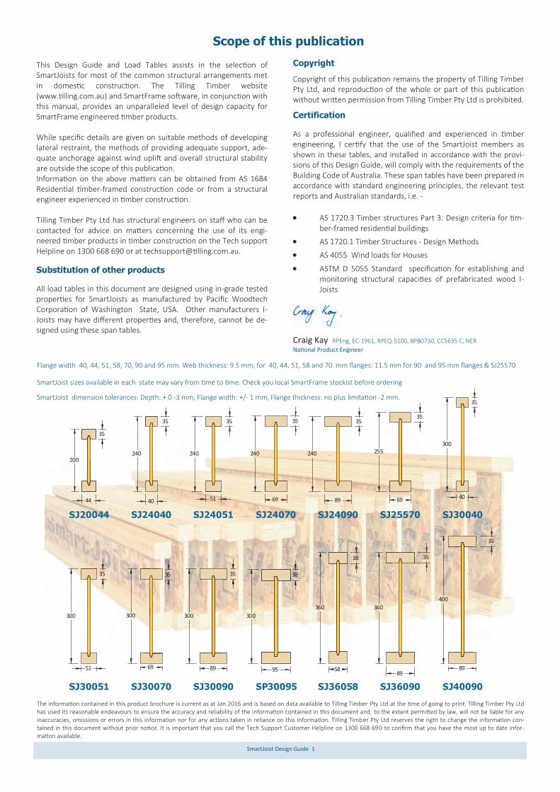
This Design Guide and Load Tables assists in the selection of SmartJoists for most of the common structural arrangements met in domestic construction. The Tilling Timber website (www.tilling.com.au) and SmartFrame software, in conjunction with this manual, provides an unparalleled level of design capacity for SmartFrame engineered timber products. While specific details are given on suitable methods of developing lateral restraint, the methods of providing adequate support, ade-quate anchorage against wind uplift and overall structural stability are outside the scope of this publication. Information on the above matters can be obtained from AS 1684 Residential timber-framed construction code or from a structural engineer experienced in timber construction. Tilling Timber Pty Ltd has structural engineers on staff who can be contacted for advice on matters concerning the use of its engi-neered timber products in timber construction on the Tech support Helpline on 1300 668 690 or at [email protected]. Substitution of other products All load tables in this document are designed using in-grade tested properties for SmartJoists as manufactured by Pacific Woodtech Corporation of Washington State, USA. Other manufacturers I-Joists may have different properties and, therefore, cannot be de-signed using these span tables.
Copyright
Copyright of this publication remains the property of Tilling Timber Pty Ltd, and reproduction of the whole or part of this publication without written permission from Tilling Timber Pty Ltd is prohibited.
Certification As a professional engineer, qualified and experienced in timber engineering, I certify that the use of the SmartJoist members as shown in these tables, and installed in accordance with the provi-sions of this Design Guide, will comply with the requirements of the Building Code of Australia. These span tables have been prepared in accordance with standard engineering principles, the relevant test reports and Australian standards, i.e. -
AS 1720.3 Timber structures Part 3: Design criteria for tim-ber-framed residential buildings
AS 1720.1 Timber Structures - Design Methods
AS 4055 Wind loads for Houses
ASTM D 5055 Standard specification for establishing and monitoring structural capacities of prefabricated wood I-Joists
Craig Kay RPEng, EC-1961, RPEQ-5100, BPB0730, CC5635 C, NER
National Product Engineer
Scope of this publication
The information contained in this product brochure is current as at Jan 2016 and is based on data available to Tilling Timber Pty Ltd at the time of going to print. Tilling Timber Pty Ltd has used its reasonable endeavours to ensure the accuracy and reliability of the information contained in this document and, to the extent permitted by law, will not be liable for any inaccuracies, omissions or errors in this information nor for any actions taken in reliance on this information. Tilling Timber Pty Ltd reserves the right to change the information con-tained in this document without prior notice. It is important that you call the Tech Support Customer Helpline on 1300 668 690 to confirm that you have the most up to date infor-mation available.
89
400
35
35
89
360
38
360
58956951
35
300
SJ25570
255
69
35
40
35
300
89
35
240
35
69
240240
35
51
35
40
240
44
35
200
SJ30051 SJ30070
300
35
SJ30090
300
35
89
SJ36058 SJ36090 SJ40090
SJ20044 SJ24040 SJ24051 SJ24070 SJ24090 SJ30040
SP30095
300
38
SmartJoist dimension tolerances: Depth: + 0 -3 mm, Flange width: +/- 1 mm, Flange thickness: no plus limitation -2 mm.
Flange width 40, 44, 51, 58, 70, 90 and 95 mm. Web thickness: 9.5 mm, for 40, 44, 51, 58 and 70 mm flanges: 11.5 mm for 90 and 95 mm flanges & SJ25570
SmartJoist sizes available in each state may vary from time to time. Check you local SmartFrame stockist before ordering

SmartJoist Design Guide 2
“The strength is in the engineering”
The SmartFrame Engineered Wood System is made up of:
World class engineered timber products:
1. SmartJoist
2. SmartLVL
3. SmartLam GLT
4. Tecbeam
Unique SmartFrame Structural Design, Detailing and Estimating Software
Full engineering support and technical advice from experienced engineers and field staff free of charge on our unique Tech Support Customer Helpline 1300 668 690.
SmartJoists The strength is in the engineering:- Strong. Stiff. Reliable. SmartJoists are engineered for heavy performance. We start with ultrasonically graded LVL, bonded with exterior adhesive for more load carrying capacity. The webs are made from stable, strong Oriented Strand Board (OSB) for superior strength and consistent performance. SmartJoists are more uniform than solid sawn joists. They stay straighter and are manufactured with no camber, so there is no chance of crown down or upside down installation. They resist shrinking, twisting, warping and splitting for squeak resistant floors and quality roofs and ceil-ings. Holes may be easily cut in the web according to the tables on page 30, allowing ducts and utilities to be run through the joists. Pre-punched 40 mm knockout holes are provided in the web for small diameter services or wiring. Save Time and Money:- Because they weigh less than solid sawn joists, SmartJoists are easier to install, saving construction time and cost. Their greater load carrying capacity allows you to space them
further apart, so it takes fewer to build the average floor or roof. And with five (5) depths from 200 to 400 mm, you will never have to compromise your design. So whether your plans call for cantilever beams in balconies, cathedral roofs or high pitched roof slopes, SmartJoists are the perfect choice. An Environmentally Sound Choice:- In addition to being cost effec-tive, SmartJoists are also an environmentally sound choice because they are made of a renewable resource – wood. So they are a better choice for building. SmartJoists have a certified Chain of Custody system to PEFC. SmartFrame Software:- Our unique SmartFrame design, detailing and estimating software offers you unparalleled design and esti-mating capabilities with engineered timber. You will get accurate designs for a wide variety of applications, printouts and joist layouts. Limitations of use - SmartJoists:-SmartJoists are to be used in dry interior environments only, fully enclosed from exposure to exterior moisture. SmartJoists are suitable for subfloor applications provided that the subfloor space is ventilated as per the BCA requirements. This means that SmartJoists must not be exposed to environments where the equilibrium moisture content of the joist will exceed 18%. Tilling Timber will not guarantee SmartJoists that have been left exposed to the weather either prior to or during construction for more than 90 days. Detailing such as cladding or lining must be used in moisture laden environments (commercial kitchens, bathrooms, wet industrial are-as, saunas, swimming pool and spa rooms etc.) and constructed in such a way as to prevent exposure of the SmartJoist to moisture. SmartJoists may be used in applications which are often exposed externally (gable ends, eaves, floor joists applications in elevated houses, cantilevered joists etc.) but must be sufficiently enclosed with a suitable cladding, lining etc. to completely prevent the expo-sure of the SmartJoist to moisture.
Tilling Timber guarantees that SmartFrame Engineered Timber products have been manufactured to exacting standards and are free from defects in workmanship and materials. At Tilling Timber, we take great pride in SmartFrame products, so if you bring to our attention prob-lems such as squeaks that you believe are caused by our products, we guarantee that a technical representative will contact you promptly to evaluate the issues and provide advice to help solve the problem Providing that any SmartFrame product is correctly designed, handled and installed, any problem caused by an unlikely defect will promptly be remedied at no cost to you. This guarantee remains valid for the expected life of your home.
Tilling Timber Pty Ltd 31-45 Orchard Street
Kilsyth Vic 3137 Priority call: 1300 668 690 e-mail: [email protected]
SmartFrame Consumer Product Warranty

SmartJoist Design Guide 3
The “feeling” that is identified when a person walks on a floor is very subjective. Some people want to feel a very stiff floor and others want some ”give” so that it softens the footing. When peo-ple say the floor “bounces”, it may be vibrating. This sensation is often caused by lack of dead load such as furniture, direct applied ceilings or other materials to absorb or dampen the vibration. AS 1720.3 standard includes as an upper limit, a 1.0 kN static load applied at mid-span as a serviceability equation to simulate the foot force effect on the design of floor joists. The differential de-flection caused by this 1 kN load is limited to 2 mm. This criteria was developed for solid section floor joists up to 6 m spans, and in some cases, experience is now showing that at the 2 mm limit, the floor performance of lightweight I-Joist floors (especially without ceilings below e.g. subfloors) may be considered unfit for purpose by some people. The two (2) alternative SmartJoist Span Table shown in this manual have been de-signed to meet the strength and serviceability criteria of:
Table 1 - AS 1720.3—2016 In this table the strength and servicea-bility limits of AS 1720.3—2016 have been used along with the recommended dynamic requirements.
Table 2 - SmartJoist Preferred Dynamics. In this table the strength and serviceability limits of AS 1720.3—2016 have been supple-mented with a EN 1995-1-1-2004 service-ability equation to better model foot force effects on I-Joist floors. This approach has been demonstrated to produce stiffer floors for those wanting a firmer feel in their timber floor.
Both tables list MAXIMUM recommended joist spans, and there-fore shorter spans in most cases should produce stiffer floors. Factors that can affect floor dynamic performance
The choice of flooring system
The depth, stiffness and mass of the joists
Spacing of joists
Fixing of sheathing to joists
Stiffness and mass of floor sheathing
Mass and stiffness of ceiling materials
Method of installation
Location and type of internal partitions and furniture
Factors that can improve floor dynamic performance
Glue/nailed and glue/screw floors will perform better than floors secured by nails alone.
Deflection of the sheathing material between joists can be reduced by decreasing the joist spacing or using a thicker and/or stiffer sheathing.
Proper installation is essential for dependable perfor-mance. Adequate and level support for the joists is necessary, as is correct fastening of the joists and sheathing.
The installation of a ceiling to the bottom flange of the joists or a similar mass/loading sharing system.
While between joist blocking has been traditionally used to pro-vide some improvement to floor dynamic performance of solid
timber joists, both testing and long experience show limited if any improvement to the dy-namic performance by mid-span blocking of I-Joist floor systems with simple blocking. If floor dynamic performance is a concern to either the cli-ent, designer or contractor, then the above variables can be altered, or additional meth-ods be incorporated to im-prove dynamic performance. Further information on the dynamic performance of light-weight timber floors can be obtained by calling the Tech Support Customer Helpline on 1300 668 or at [email protected].
Large area ceramic tiled floors The modern trend to large size ceramic tiles has introduced a new design challenge for all floor substrates. Smaller numbers of grout-ed joins between larger tiles means that any deflection of the floor has to be larger per grouted joint, thus increasing the probability of cracking. AS 3958.1—2007 (incudes amendment 1-2010) Ceramic tiles Part 1: Guide to the installation of ceramic tiles limits the total deflec-tion of the floor (Dead Load + Live Load ) to L/360. This supplemen-tary deflection limit is not one that is normally considered in the design of timber floors. The spans listed within Tables 2-4 meets the additional AS 3958.1—2007 Ceramic tiles Part 1: Guide to the installation of ceramic tiles deflection limits.
General information - about floor performance

SmartJoist Design Guide 4
SmartJoist Code
Depth (mm)
Flange width (mm)
Flange Thickness
(mm)
Web thickness
(mm)
Self weight (kg/m)
Moment (kN.m)
Shear (kN)
EI x 106 (kN.mm2)
GJ x 106 N.mm2)
GAw x 106 (N.mm2)
End reaction
(kN)
Max interior reactions
42 mm bearing (kN)
90 mm bearing (kN)
SJ20044 200 44 35 9.5 2.7 10.0 10.5 355 997 1.78 8.60 14.7 19.6
SJ24040 240 40 35 9.5 2.8 8.8 13.1 500 907 2.27 8.60 14.7 19.6
SJ24051 240 51 35 9.5 3.2 11.4 13.1 635 1156 2.27 9.5 17.0 22.4
SJ24070 240 69 35 9.5 4.0 15.3 13.1 852 1564 2.33 11.2 20.5 25.1
SJ24090 240 89 35 11.5 5.1 19.8 16.2 1097 2017 2.27 12.1 25.7 33.2
SJ25570 255 69 35 11.5 4.4 16.6 17.3 988 1154 2.46 11.2 20.5 25.1
SJ30040 300 40 35 9.5 3.1 11.3 17.0 844 907 3.01 8.6 14.7 19.6
SJ30051 300 51 35 9.5 3.6 14.7 17.0 1069 1156 3.01 9.5 17.0 22.4
SJ30070 300 69 35 9.5 4.4 19.7 17.0 1432 1564 3.01 11.2 20.5 25.1
SJ30090 300 89 35 11.5 5.6 26.0 20.7 1843 2017 3.01 12.1 25.7 33.2
SP30095 300 95 38 11.5 6.6 30.1 20.7 2087 2140 3.01 12.1 25.9 33.2
SJ36058 360 58 38 9.5 4.4 21.9 20.9 1953 1683 3.67 11.2 21.4 24.1
SJ36090 360 89 35 11.5 6.0 31.5 25.2 2791 2017 3.66 12.1 25.7 33.2
SJ40090 400 89 35 11.5 6.3 35.1 28.3 3537 2017 4.23 12.1 25.7 33.2
Designing with SmartJoists®
The design information contained within this Design Guide is for the properties of SmartJoist® I-Joists only. Other manufacturers’ I-Joists may have different properties and therefore cannot be de-signed using this information.
Characteristic properties
Strength reduction factors The strength reduction factor for calculating the design capacities of structural members shall be taken from the table below, refer-enced from AS 1720.1 –2010
Duration of load
The duration of load factor k1 for strength is defined within clause 2.4 of AS 1720.1. The duration of load factor J2 for deflection is defined below.
Deflection (Bending deflection + shear deflection)
Bending deflection—use standard engineering formula Shear deflection - for a uniformly distributed load w, over a span L
Partial seasoning factor SmartJoists are a seasoned timber product, generally k4 equals 1. Where the SmartJoists are subjected to conditions in which the average moisture content for a 12 month period is expected to exceed 15%, the characteristic capacity shall be decreased. The value of k4 shall be the greater of: a.
b. Where EMC is the highest value of the annual moisture content (percent) that the timber will attain in service. Length and position of bearing The k7 bearing factor is defined is clause 2.4.4 of AS 1720.1
Load sharing Because of the reduced variability of strength values of SmartJoist compared to solid timber , the load sharing factor k9 = 1.0.
Stability The stability factor k12 is defined within Appendix E of AS 1720.1
Temperature For covered timber structures under ambient conditions, no mod-ification for strength need be made for the effect of temperature (i.e., k6 equals 1.0) except that where seasoned timber is used in structures erected in coastal regions of Queensland north of lati-tude 25°S, and all other regions of Australia north of latitude 16°S, the strength shall be modified by a factor k6 of 0.9.
Application of SmartJoist as a structural member
Category 1 Category 2 Category 3
Structural members for houses for which failure would be un-
likely to affect an area greater than 25 m2;
OR secondary members
in structures other than houses
Primary structural members in structures
other than houses; OR
elements in houses for which failure would be likely to affect an area*
greater than 25 m2
Primary structural members in struc-tures intended to
fulfil essential services or post disaster function
Strength reduction factor Ø *
0.95 0.90 0.80
* AS 1720.1:2010 Table 2.1
Dimensional tolerances:
Length ± 10 mm
Depth +0, -3 mm
Flange width ± 10 mm
Flange thickness No plus limitation, -2
Treatment options:
H2s (standard) and H2 treatment to AS 1604.2 and AS 1604.4
Duration of action Bending and shear
Short term 1 day 1.0
Long term > 12 months 2.0
AwGw
wL
EI x
wLjy
8
2
384
5 4
2
70
10
153001
4
4
.k
EMC..k
SmartJoist Design Guide 5
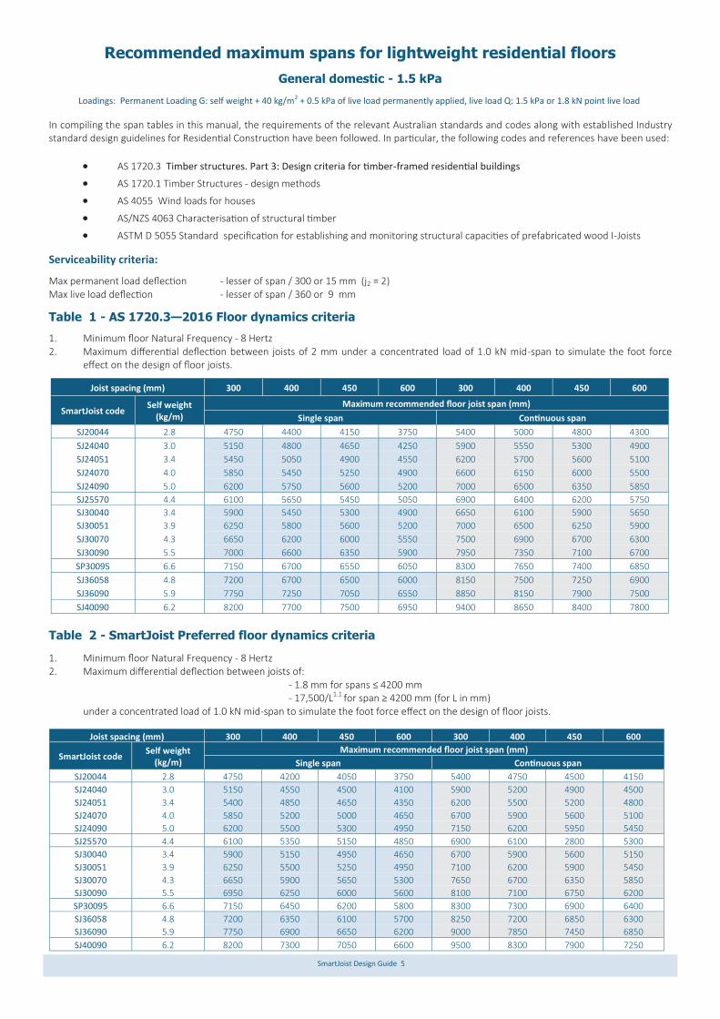
In compiling the span tables in this manual, the requirements of the relevant Australian standards and codes along with established Industry standard design guidelines for Residential Construction have been followed. In particular, the following codes and references have been used:
AS 1720.3 Timber structures. Part 3: Design criteria for timber-framed residential buildings
AS 1720.1 Timber Structures - design methods
AS 4055 Wind loads for houses
AS/NZS 4063 Characterisation of structural timber
ASTM D 5055 Standard specification for establishing and monitoring structural capacities of prefabricated wood I-Joists
Serviceability criteria:
Max permanent load deflection - lesser of span / 300 or 15 mm (j2 = 2) Max live load deflection - lesser of span / 360 or 9 mm
Table 1 - AS 1720.3—2016 Floor dynamics criteria
1. Minimum floor Natural Frequency - 8 Hertz 2. Maximum differential deflection between joists of 2 mm under a concentrated load of 1.0 kN mid-span to simulate the foot force
effect on the design of floor joists.
Table 2 - SmartJoist Preferred floor dynamics criteria
1. Minimum floor Natural Frequency - 8 Hertz 2. Maximum differential deflection between joists of: - 1.8 mm for spans ≤ 4200 mm - 17,500/L1.1 for span ≥ 4200 mm (for L in mm) under a concentrated load of 1.0 kN mid-span to simulate the foot force effect on the design of floor joists.
Recommended maximum spans for lightweight residential floors
Loadings: Permanent Loading G: self weight + 40 kg/m2 + 0.5 kPa of live load permanently applied, live load Q: 1.5 kPa or 1.8 kN point live load
General domestic - 1.5 kPa
Joist spacing (mm) 300 400 450 600 300 400 450 600
SmartJoist code Self weight
(kg/m)
Maximum recommended floor joist span (mm)
Single span Continuous span
SJ20044 2.8 4750 4400 4150 3750 5400 5000 4800 4300
SJ24040 3.0 5150 4800 4650 4250 5900 5550 5300 4900
SJ24051 3.4 5450 5050 4900 4550 6200 5700 5600 5100
SJ24070 4.0 5850 5450 5250 4900 6600 6150 6000 5500
SJ24090 5.0 6200 5750 5600 5200 7000 6500 6350 5850
SJ25570 4.4 6100 5650 5450 5050 6900 6400 6200 5750
SJ30040 3.4 5900 5450 5300 4900 6650 6100 5900 5650
SJ30051 3.9 6250 5800 5600 5200 7000 6500 6250 5900
SJ30070 4.3 6650 6200 6000 5550 7500 6900 6700 6300
SJ30090 5.5 7000 6600 6350 5900 7950 7350 7100 6700
SP30095 6.6 7150 6700 6550 6050 8300 7650 7400 6850
SJ36058 4.8 7200 6700 6500 6000 8150 7500 7250 6900
SJ36090 5.9 7750 7250 7050 6550 8850 8150 7900 7500
SJ40090 6.2 8200 7700 7500 6950 9400 8650 8400 7800
Joist spacing (mm) 300 400 450 600 300 400 450 600
SmartJoist code Self weight
(kg/m)
Maximum recommended floor joist span (mm)
Single span Continuous span
SJ20044 2.8 4750 4200 4050 3750 5400 4750 4500 4150
SJ24040 3.0 5150 4550 4500 4100 5900 5200 4900 4500
SJ24051 3.4 5400 4850 4650 4350 6200 5500 5200 4800
SJ24070 4.0 5850 5200 5000 4650 6700 5900 5600 5100
SJ24090 5.0 6200 5500 5300 4950 7150 6200 5950 5450
SJ25570 4.4 6100 5350 5150 4850 6900 6100 2800 5300
SJ30040 3.4 5900 5150 4950 4650 6700 5900 5600 5150
SJ30051 3.9 6250 5500 5250 4950 7100 6200 5900 5450
SJ30070 4.3 6650 5900 5650 5300 7650 6700 6350 5850
SJ30090 5.5 6950 6250 6000 5600 8100 7100 6750 6200
SP30095 6.6 7150 6450 6200 5800 8300 7300 6900 6400
SJ36058 4.8 7200 6350 6100 5700 8250 7200 6850 6300
SJ36090 5.9 7750 6900 6650 6200 9000 7850 7450 6850
SJ40090 6.2 8200 7300 7050 6600 9500 8300 7900 7250

SmartJoist Design Guide 6
Table 3 - SmartJoist –65 kg/m2 - grout and tiled floor
1. Minimum floor Natural Frequency - 8 Hertz 2. Maximum differential deflection between joists of: - 1.8 mm for spans ≤ 4200 mm - 17,500/L1.1 for span ≥ 4200 mm under a concentrated load of 1.0 kN mid-span to simulate the foot force effect on the design of floor joists. 3. Total deflection of the floor (Dead Load + Live Load ) to L/360 as per AS 3958.1—2007 (incudes amendment 1-2010) Ceramic tiles Part
1: Guide to the installation of ceramic tiles
Table 4 - SmartJoist –135 kg/m2 - 40 mm grout and tiled floor
1. Minimum floor Natural Frequency - 8 Hertz 2. Maximum differential deflection between joists of: - 1.8 mm for spans ≤ 4200 mm - 17,500/L1.1 for span ≥ 4200 mm under a concentrated load of 1.0 kN mid-span to simulate the foot force effect on the design of floor joists. 3. Total deflection of the floor (Dead Load + Live Load ) to L/360 as per AS 3958.1—2007 (incudes amendment 1-2010) Ceramic tiles Part
1: Guide to the installation of ceramic tiles
Recommended maximum spans for residential floors with ceramic tiles
Loadings: Permanent Loading G: self weight + 65kg/m2 + 0.5 kPa of live load permanently applied, live load Q: 1.5 kPa or 1.8 kN point live load
General domestic - 1.5 kPa
Loadings: Permanent Loading G: self weight + 135 kg/m2 + 0.5 kPa of live load permanently applied, live load Q: 1.5 kPa or 1.8 kN point live load
Joist spacing (mm) 300 400 450 600 300 400 450 600
SmartJoist code Self weight
(kg/m)
Maximum recommended floor joist span (mm)
Single span Continuous span
SJ20044 2.8 4500 4200 3900 3500 5400 4700 4500 4100
SJ24040 3.0 4900 4550 4400 4000 5900 5200 4900 4500
SJ24051 3.4 5200 4800 4600 4300 6200 5500 5200 4800
SJ24070 4.0 5500 5200 5000 4650 6700 5900 5600 5100
SJ24090 5.0 5800 5450 5300 4900 7050 6250 5950 5450
SJ25570 4.4 5750 5350 5150 4850 6900 6100 5800 5350
SJ30040 3.4 5600 5100 4950 4650 6700 5900 5600 5150
SJ30051 3.9 5900 5500 5250 4950 7100 6200 5900 5450
SJ30070 4.3 6300 5900 5650 5300 7600 6700 6350 5850
SJ30090 5.5 6650 6200 6000 5600 8000 7100 6750 6200
SP30095 6.6 6800 6350 6200 5750 8200 7300 6950 6400
SJ36058 4.8 6800 6350 6100 5700 8200 7200 6850 6300
SJ36090 5.9 7350 6800 6650 6200 8850 7850 7450 6850
SJ40090 6.2 7800 7300 7050 6600 9400 8300 7900 7250
Joist spacing (mm) 300 400 450 600 300 400 450 600
SmartJoist code Self weight
(kg/m)
Maximum recommended floor joist span (mm)
Single span Continuous span
SJ20044 2.8 4000 3700 3600 3250 4900 4500 4350 3950
SJ24040 3.0 4350 4050 3900 3650 5300 4950 4850 4500
SJ24051 3.4 4600 4300 4150 3900 5650 5250 5100 4750
SJ24070 4.0 4950 4550 4400 4100 6050 5650 5450 5050
SJ24090 5.0 5200 4800 4650 4350 6400 5920 5750 5350
SJ25570 4.4 5100 4750 4650 4300 6250 5850 5650 5250
SJ30040 3.4 5000 4600 4450 4100 5850 5400 5250 4800
SJ30051 3.9 5250 4850 4700 4300 6150 5750 5550 5150
SJ30070 4.3 5600 5200 5000 4650 6500 6100 5950 5500
SJ30090 5.5 5900 5500 5300 4950 6900 6400 6250 5800
SP30095 6.6 6100 5650 5500 5100 7450 6950 6750 6250
SJ36058 4.8 6050 5650 5450 5050 7100 6600 5450 5950
SJ36090 5.9 6500 6100 5900 5450 7600 7100 6900 6450
SJ40090 6.2 6950 6500 6250 5750 8100 7550 7300 6800

SmartJoist Design Guide 7
Recommended maximum spans for residential floors (cont’d)
Flooring: Spans are suitable for solid timber, particle board and ply flooring. Floor sheathing glued and nailed to the joists will improve floor rigidity. Where a heavy overlay material is to be applied, such as thick mortar bed tiled or slate floors, the permanent load allowance should be in-creased to 1.2 kPa. A reduction of joist spacing can be used to accommodate this extra permanent load. A satisfactory result can be achieved by adopting the maximum spans for 600 mm and 450 mm spacing but installing the joists at 450 mm and 300 mm spacing respectively.
Continuous spans: For beams which are continuous over two unequal spans, the design span and the "resultant span description" depend on the percentage difference between the two spans as shown below:
Effective span Resultant span description Span difference
10% max main span continuous
10 - 30% 1.1 x main span continuous
above 30% diff main span single
Main span Second span
span difference = (main span - second span)
X 100 (main span + second span)
SmartJoist Design /Effective span
Normal structural analysis uses the centreline representation of the member. The term “span” can be defined in a number of ways and these are defined as follows: Clear Span. This is the distance between the faces of any support. It is generally the one easiest to measure and read from the draw-ings
Nominal span/centre-line span. This is the distance between the centre of the supports. This span is used to determine bending moments and deflections for continuous spaning members
Design span/Effective span. This is the span used for single span members to determine the bending moment, the slenderness of bending members and the deflections. In AS 1720.1 this is the dimension referred to as “L”, and is defined below.
Design span/effective span is the distance between -
The centre of the bearing at each end of a beam where the bearing lengths have NOT been conservatively sized
The centre of notional bearing that have been sized appro-priately, where the size of the bearing IS conservative.
Diagram (a) shows beam where bearings have been designed appropriately. The effective span is taken as the distance between the centre of each bearing area
Diagram (b) shows beam where bearings at each end have been oversized. (This is fre-quently the case for beams that bear onto brickwork or concrete walls where the thick-ness of the wall is in excess of the area required to give the beam bearing capacity). To find the correct effective span: 1. Calculate the minimum bearing re-
quired to carry the loads satisfactorily 2. Add minimum bearing length to “clear
span” distance
Are a of sup port req uired fo r bearing
len gth of origin al be aring ( overs ized)
Len gth of effe ctive bearing
Clear span (distanc e betw een face of su pports )
Effe ctive (d esign) s pan
Clear span (distanc e betw een face of su pports )
Effe ctive (d esign) s pan
(a)
(b)

SmartJoist Design Guide 8
Accidents can be avoided under normal conditions by following these guidelines: 1. Brace each joist as it is erected. Joists must be nailed to
supports and all hangers, blocking, rim joists. X - bridging at supports must be completely installed and properly nailed. (see general notes and details)
2. Brace the ends of cantilevers (overhangs) with closure panels, rim joist or x - bridging (see general notes and de-tails)
3. Lateral brace the top flange of each joist, to prevent side-ways buckling or rollover which may occur under light con-struction loads, such as a worker and/or a layer of un-nailed sheathing. Fully installed permanent sheathing or temporary struts to the top flange of each joist (see
‘Typical SmartJoist floor framing’) can accomplish lateral bracing. Temporary struts must be nailed to a lateral re-straint at the end of bay such as a braced wall or tempo-rary (or permanent) sheathing nailed to the first 1200 mm of the joist at the end of the bay (see ‘Typical floor or roof framing’)
4. Permanent sheathing must be completely installed and properly nailed before additional loads can be placed on the system
5. The integrity and safe use of these products can be seriously impaired if they are damaged. Do not install any damaged products. Contact your SmartFrame representative or the Tech Support Customer Helpline on 1300 668 690 if any product damage is noted.
Do not allow workers or loads on SmartJoists until all blocking, hangers, rim joists, nailing and temporary bracing are installed as specified below. Serious acci-dents or injury can result from failure to follow these guidelines.
Safety Warning
Handling and storage of SmartJoists
SmartJoists should be stacked in the upright position to avoid any damage during handling or storage.
Store SmartJoists flat on a hard, dry surface
If surface isn't paved, the ground should be covered with a polythene film
Keep covered with waterproof material that allows bundles to "breathe"
Use bearers (bolsters) between the ground and the first bundle (4 metre max spacing)
Use 100 x 50 timber flat between bundles at same spacing as bolsters
Take great care to rewrap remaining material after opening bundles
Wood "grows" in thickness and depth when allowed to get wet....KEEP DRY!
Wood with high MC has short term reduction in Characteristic Strengths …. KEEP DRY!
Under NO circumstances are stored SmartJoists to be in contact with the ground.
Bearers at a maximum of 4000 mm centres
Use bearers to keep stacked material away from damp surfaces. Align bearer vertically

SmartJoist Design Guide 9
SmartJoists - General information
Start toe nail app roximately 2/3 up the s ide of the f lange.
Nai ls sho uld be as far as practical from the
e nd of the jo ist
Do NOT s tart to e nai l into the c orne r of th e flan geor the to p of th e flan ge.
MAXIMU M Nail diameter 3 .15 mm
1. Except where otherwise noted, 30 mm minimum bearing is required at joist ends and 42 mm minimum bearing is required at intermediate supports.
2. Nail joists at each bearing with 2 of 3.15 Ф x 65 nails, using one each side placed 30 mm from the end to avoid splitting as per detail below.
3. SmartJoist blocking or SmartRim - face nail to bearing plate with 3.15 Ф x 65 nails at 150 mm centres. Nail rim joist to the end of the top and bottom flange of each SmartJoist with 1 off 3.15 Ф x 65 nail, use 1 off 3.75 Ф x 75 nail top and bottom with joists with 58, 70 or 90 mm wide flanges.
4. 17-21 mm SmartRim - toe nail to bearing plate with 3.15 Ф x 65 nails at 150 centres or 4.5 Ф x 75 nails at 300 centres. Nail rim to the end of the top and bottom flanges of each SmartJoist with 1 3.15 Ф x 65 nails.
5. Sheathing nailing to top flange (Joists must be fully braced
before sheathing is nailed or screwe.
Do not use nails or screws larger than those shown above when attaching sheathing to flanges of SmartJoists
Minimum nail spacing is shown above, maximum nail spac-ing is set by the flooring manufacturer, in absence of manu-facturers data, 300 mm centres
SmartJoists are manufactured with Douglas Fir (Oregon) flanges with OSB webs, both having a durability rating of class 4, the equiv-alent rating as some Ash type Eucalypts. Untreated SmartJoists should therefore not be used where the equilibrium moisture con-tent is likely to remain above 18 % for an extended period. Untreated SmartJoists are suitable in the internal, fully protected, ventilated and the external above ground, protected zones of the structure as shown in appendix B of AS 1684. Untreated SmartJoist is not suitable for external above ground, exposed or humid indoor conditions, such as swimming pool enclosures.
Moisture effects on SmartJoists
SmartJoist is supplied WITHOUT any short term construction sealer, but once framed into a structure may be exposed to the weather for a limited time (not greater than 3 months) without negative affect, BUT, it may exhibit some effects of this exposure. The wood fibre in SmartJoists, like all wood products, is hygroscop-ic, which means it has an affinity for water. The wood fibre in SmartJoist will readily take up and release moisture in response to changes in the local environment. Moisture exposure will lead to dimensional change. While the products will withstand normal exposure, excessive exposure during distribution, storage or con-struction may lead to dimensional changes that affect serviceability. These changes include twisting, bowing or expansion to dimensions to beyond the specified tolerance of the product in the “as-manufactured” condition.
As an organic material, mould and mildew may grow on untreated wood products if moisture is present. Prolonged periods of high moisture may also support the growth of wood decay fungi, which is another reason to follow proper methods of storage and handling of SmartJoists. The table below shows the moisture content of SmartJoists as a function of humidity.
Wetting during construction may lead to temporary elevated mois-ture content and dimensional changes. Once covered, the SmartJoists will ultimately dry and re-equilibrate to the ambient humidity conditions, but some expansion or swelling may remain after drying.
Durability and exposure to moisture
Moisture content of wood products %(1)
Relative Humidity % LVL Flange MC OSB web
10 1.2 0.8
20 2.8 1.0
30 4.6 2.0
40 5.8 3.6
50 7.0 5.2
60 8.4 6.3
70 11.1 8.9
80 15.3 13.1
90 19.4 17.2
(1). Approximate moisture content at 210C
Minimum single row fastener spacing into SmartJoist flanges
SmartJoist flange width Fastener type
and size 40 mm flange
44 mm flange
51 mm flange
58-70 mm flange
90 mm flange
Nails
2.8 x 60 75 75 50 50 50
3.15 x 60 100 90 75 75 75
Screws
9g x 45 150 150 75 75 75
10g x 50 150 150 100 75 75
Min imum nail or s crew s pacing from ta ble
Off set se cond row of n ails o r s crews

SmartJoist Design Guide 10
Tighter effective nail spacing may be obtained by offsetting nail rows a minimum of 12 mm and maintaining a 10 mm minimum edge distance.
7. All joists require lateral support at end bearings using blocking or rim material.
8. The top flanges must be kept straight within 10 mm of the true alignment.
9. All roof details are valid to a maximum angle of 35° (as per AS 1684
10. All nails are steel nails complying with AS 2334 - 1980 Steel nails
- Metric series. Nail gun nails of similar length and diameter may be substituted for the above provided that they are manu-factured with properties equivalent to the nails in the above code.
11. Install all hangers to the manufacturers installation instructions, taking particular attention to the use of the correct nails. Never use clouts or brads.
12. Prescriptive code requirements for mid span blocking of solid timber joists are not applicable to SmartJoists.
SmartJoists - General notes (Cont’d)
Typical SmartJoist floor details
Blocking and lateral restraint General notes: SmartJoists designed and constructed as per this Design Guide do not require mid-span blocking. The exception to this is for light-weight subfloors where there is no lining to the underside of the joists. For more information on this topic, see page 3 ‘ABOUT FLOOR PERFORMANCE’. Blocking within a structure falls within two (2) quite distinct stages: Temporary or during construction blocking to prevent roll over of joists before the installation of floor sheeting.
Permanent blocking to provide resistance to racking loads through the floor diaphragm, transfer of vertical wall loads and to provide torsional resistance to the end of the joist.
The provision contained within AS1684 Residential timber-framed
construction code dealing with blocking for deep joists, is “during
construction” or “temporary” blocking, designed only to prevent
the roll over of the deep joists prior to the floor sheeting being
attached. This level of blocking can form a part of any overall
blocking system, but was never intended to provide the total
amount of racking resistance or vertical load transfer requirements
within this floor diaphragm.
The lateral bracing requirements of the structure, unless there is full blocking of exterior walls, must be calculated in each individual case. Advice on this matter is obtainable from AS1684 Residential timber-framed construction code.
1.0 Joists bearing onto external walls
1.1 Loads at joist support connection The ends of floor joists that bear onto a support experience exter-nal loads other than the floor dead and live loads, as shown. Any I-Joist, with it’s small cross sectional area, needs to have its end bearing capacity considered as part of the design process.
Further, as a holistic approach to the consideration of the lateral stability of the complete structure, it is necessary to consider the availability of racking and shear resistance through the floor dia-phragm.
1. Racking and shear effects due to wind and earthquake loads
2. Vertical loads on joists due to upper wall, floors and roof 3. Unsightly deflections in the edges of unsupported sheet
flooring may be experienced if heavy items of furniture are placed close to sheet edges.

SmartJoist Design Guide 11
Typical SmartJoist Floor details (Cont’d)
1.2 Stages of blocking/bracing 1.2.1 Temporary (during construction) end blocking Temporary or during construction blocking of the ends of joists
over external wall must comply with the requirements as shown in
the “SAFETY WARNING” on page 6 and as shown in the “TYPICAL
SmartJoist FLOOR FRAMING” diagram on page 14.
This is summarised as:
Temporary struts, fastened to top of SmartJoist, connected back to braced supports.
Temporary floor sheeting nailed to the first 1200 mm of joists at the end of the bay, in combination with struts, if no connection to a braced wall can be made.
1.2.2 Permanent end blocking/bracing
Permanent blocking (bracing) to be effective in providing adequate transfer of racking and shear loads through the floor diaphragm must comply with the details as shown in “TYPICAL SmartJoist FRAMING” diagram on page 17. In essence, fully block the ends of all joists at their bearing point on external walls, as per one of the options shown in details F1- F4. This permanent blocking/bracing provides: 1. A satisfactory mechanism to transfer racking loads through
the floor diaphragm.
2. Vertical load transfer independent of the floor joist.
3. Support to the end of the floor sheeting (Platform floors only). Heavily loaded furniture legs have been known to cause large deflections and even failures at the edges of sheet flooring.
4. Torsional restraint to the end of floor joists, improving the joists structural performance.
2.0 Interior supports
2.1 Ends of simple spans
Where SmartJoists are discontinuous over interior supports, install the temporary strut bracing as per “SAFETY WARNING” on page 8.
2.2 Continuous spans
Continuous joists over internal supports do not require blocking, other than the temporary top flange struts as shown in the “SAFETY WARNING” on page 8, except in the following circum-stances:
Load bearing walls bear onto the joists at their support. (Details F7 or F8 apply)
Shear resistance is required in internal walls (This is a func-tion of shear resistance, and is not related to the structural adequacy of the joist itself.)
3.0 Blocking and wall plates
Wall plates in the frame are required to transfer vertical loads into the support structure below. These wall plates may be supported at 450 or 600 mm ctrs, thus acting as a beam between supports, bending about its weaker axis. When concentrated loads act at the centre of this wall plate, the bending and deflection effects can be quite significant. The full blocking of external and load bearing walls, as shown in details F1-F4, can act as a beam transferring these loads to the support structure below, thus reducing the beam effect of the wall plates. Unless there is a requirement for double wall plates for a reason OTHER than the beam effect between supports, walls blocked as per detail F1-F4 and general notes #2, #3, and #4 provide sufficient beam action to allow single wall plates.
Low er sto rey top plate
Upp er sto rey L OAD B EARIN G stud s
Floo r sheetssecu relynailed to blo cking
Blo cking as per detail F1 - F4 of the SmartJo ist Des ign G uide.
Low er sto rey stu ds
Sma rtJoist floo r joists
SmartJoist Design Guide 12
SmartRim
Doo r or wi ndow o pening
Top plate
Top plate
H min
2/3 H Max
H
Top plateHo le of 4 0 mm or le ss
75mmMin
Min 2 x d 1
Hd2< d1
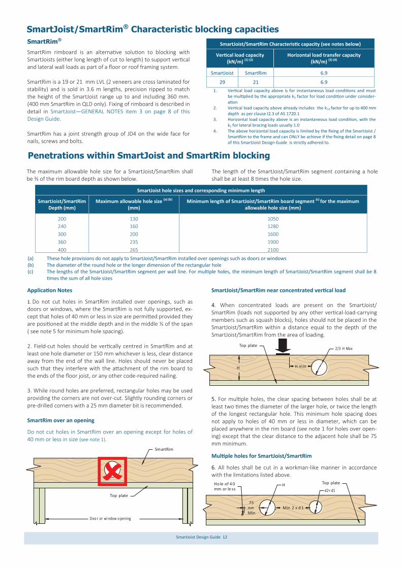
The maximum allowable hole size for a SmartJoist/SmartRim shall be ⅔ of the rim board depth as shown below.
The length of the SmartJoist/SmartRim segment containing a hole shall be at least 8 times the hole size.
SmartJoist hole sizes and corresponding minimum length
SmartJoist/SmartRim Depth (mm)
Maximum allowable hole size (a) (b) (mm)
Minimum length of SmartJoist/SmartRim board segment (c) for the maximum allowable hole size (mm)
200 130 1050
240 160 1280
300 200 1600
360 235 1900
400 265 2100
Application Notes
1. Do not cut holes in SmartRim installed over openings, such as doors or windows, where the SmartRim is not fully supported, ex-cept that holes of 40 mm or less in size are permitted provided they are positioned at the middle depth and in the middle ⅓ of the span ( see note 5 for minimum hole spacing). 2. Field-cut holes should be vertically centred in SmartRim and at least one hole diameter or 150 mm whichever is less, clear distance away from the end of the wall line. Holes should never be placed such that they interfere with the attachment of the rim board to the ends of the floor joist, or any other code-required nailing. 3. While round holes are preferred, rectangular holes may be used providing the corners are not over-cut. Slightly rounding corners or pre-drilled corners with a 25 mm diameter bit is recommended. SmartRim over an opening
Do not cut holes in SmartRim over an opening except for holes of 40 mm or less in size (see note 1).
SmartJoist/SmartRim near concentrated vertical load 4. When concentrated loads are present on the SmartJoist/SmartRim (loads not supported by any other vertical-load-carrying members such as squash blocks), holes should not be placed in the SmartJoist/SmartRim within a distance equal to the depth of the SmartJoist/SmartRim from the area of loading.
5. For multiple holes, the clear spacing between holes shall be at least two times the diameter of the larger hole, or twice the length of the longest rectangular hole. This minimum hole spacing does not apply to holes of 40 mm or less in diameter, which can be placed anywhere in the rim board (see note 1 for holes over open-ing) except that the clear distance to the adjacent hole shall be 75 mm minimum.
Multiple holes for SmartJoist/SmartRim
6. All holes shall be cut in a workman-like manner in accordance with the limitations listed above.
(a) These hole provisions do not apply to SmartJoist/SmartRim installed over openings such as doors or windows (b) The diameter of the round hole or the longer dimension of the rectangular hole (c) The lengths of the SmartJoist/SmartRim segment per wall line. For multiple holes, the minimum length of SmartJoist/SmartRim segment shall be 8
times the sum of all hole sizes
Penetrations within SmartJoist and SmartRim blocking
SmartJoist/SmartRim® Characteristic blocking capacities
SmartRim®
SmartRim rimboard is an alternative solution to blocking with SmartJoists (either long length of cut to length) to support vertical and lateral wall loads as part of a floor or roof framing system. SmartRim is a 19 or 21 mm LVL (2 veneers are cross laminated for stability) and is sold in 3.6 m lengths, precision ripped to match the height of the SmartJoist range up to and including 360 mm. (400 mm SmartRim in QLD only). Fixing of rimboard is described in detail in SmartJoist—GENERAL NOTES item 3 on page 8 of this Design Guide. SmartRim has a joint strength group of JD4 on the wide face for nails, screws and bolts.
1. Vertical load capacity above is for instantaneous load conditions and must be multiplied by the appropriate k1 factor for load condition under consider-ation
2. Vertical load capacity above already includes the k12 factor for up to 400 mm depth as per clause I2.3 of AS 1720.1
3. Horizontal load capacity above is an instantaneous load condition, with the k1 for lateral bracing loads usually 1.0
4. The above horizontal load capacity is limited by the fixing of the SmartJoist /SmartRim to the frame and can ONLY be achieve if the fixing detail on page 8 of this SmartJoist Design Guide is strictly adhered to.
SmartJoist/SmartRim Characteristic capacity (see notes below)
Horizontal load transfer capacity (kN/m) (3) (4)
Vertical load capacity (kN/m) (1) (2)
SmartJoist SmartRim 6.9
29 21 6.9

SmartJoist Design Guide 13
Joist hanger selection
The joist hangers below have been developed specifically for the flange widths for SmartJoists are manufactured using Z275 light-gauge steel, having zinc coating of 275 gsm (total weight). AS1684.2-2010 and AS1684.3-2010-Australian Standards for Resi-dential Timber Frame Construction stipulates a minimum Z275 steel for all sheet metal products used in an internal environment.
Other joist hangers may be used with SmartJoists but it is the responsibility of the specifier of these alternative joists hangers to ensure that:
i. they suit the SmartJoist flange widths and do not require any cutting or packing of the flanges
ii. they are manufacturer from Z275 light-gauge steel iii. they have the adequate capacity for the anticipat-
ed end reaction
Fixing of joist hangers
1. Hand driven nails - The joist hangers in the table below are supplied by Tilling Timber as part of a SmartFrame order with the manufacturer recom-mended nails. All holes are to be filled with the specified nails in order to achieve the stated hang-er capacity.
2. Gun nails - While the use of gun nails may be common, unless the gun nails are of a minimum 40 x 3.33 diameter, the hanger capacities listed cannot be assumed
3. Screws - The equivalent number of 35 x 6 gauge bugle-head or wafer-head wood screws may be used in lieu of the supplied nails. Increased capaci-ties can be achieved by using screws. Advice on the capacities of the joist hangers listed below with screws replacing the nails can be obtained by contacting the Tech Support Customer Helpline on 1300 668 690.
Corrosion protection The standard range of joist hangers made from Z275 light-gauge steel, having zinc coating of 275 gsm is adequate only for INTER-NAL applications in most corrosion environments, except areas that are classified as heavy industrial or those subject to high hu-midity (e.g. enclosed swimming pools) etc. Under these circum-stances, seek advice from experts as special protection will be required. Note: INTERNAL areas are those within the building envelope that are kept permanently dry. In areas outside the building envelope that are exposed to repeated wetting (EXTERNAL areas), stainless steel products or equivalent should be considered. Some alterna-tives include hot dip galvanised or powder coated steel, which are not Tilling Timber stock items. For more detailed information contact the Tech Support Custom-er Helpline on 1300 668 690 or at [email protected].
SmartJoist hangers
SmartJoist
Face mount code
Down hanger
capacity ΦkN *
No of face nails
Nail size (mm)
Top mount code
Down hanger
capacity ΦkN *
No of face nails
to support
No of top
nails
No of nails to joist
Nail size (mm)
Single joist face mounts Single joist top mount
SJ20044 20044F 6.2 8 3.75 x 40 20044T 5.7 2 6 2 3.75 x 40
SJ24040 24040F 7.8 10 3.75 x 40 24040T 5.7 2 6 2 3.75 x 40
SJ24051 24051F 7.8 10 3.75 x 40 24051T 5.7 2 6 2 3.75 x 40
SJ24070 24070F 7.8 10 3.75 x 40 24070T 5.7 2 6 2 3.75 x 40
SJ24090 24090F 7.8 10 3.75 x 40 24090T 5.7 2 6 2 3.75 x 40
SJ25570 25570F 7.8 10 3.75 X 40 N/A
SJ30040 30040F 9.3 12 3.75 x 40 30040T 5.7 2 6 2 3.75 x 40
SJ30051 30051F 9.3 12 3.75 x 40 30051T 5.7 2 6 2 3.75 x 40
SJ30070 30070F 9.3 12 3.75 x 40 30070T 5.7 2 6 2 3.75 x 40
SJ30090 30090F 9.3 12 3.75 x 40 30090T 5.7 2 6 2 3.75 x 40
SP30095 30095F 9.3 12 3.75 X 40 N/A
SJ36058 36058F 10.9 14 3.75 x 40 36058T 5.7 2 6 2 3.75 x 40
SJ36090 36090F 10.9 14 3.75 x 40 36090T 5.7 2 6 2 3.75 x 40
SJ40090 40090F 10.9 14 3.75 x 40 40090T 5.7 2 6 2 3.75 x 40
Double joist face mounts Double joist top mounts
2/SJ20044 20044DF 6.2 8 3.75 x 40 N/A
2/SJ24040 N/A 24040DT
2/SJ24051 24051DF 6.2 8 3.75 x 40 24051DT 5.7 2 2 6 3.75 x 40
2/SJ24070 24070DF 7.8 10 3.75 x 40 24070DT 5.7 2 2 6 3.75 x 40
2/SJ24090 24090DF 7.8 10 3.75x40 Pryda BBT 15 3(1) 2 3.75 x 40
2/SJ25570 N/A N/A
2/SJ30040 N/A N/A
2/SJ30051 30051DF(2) 6.2 8 3.75 x 40 30051DT 5.7 2 2 4 3.75 x 40
2/SJ30070 30070DF 9.3 12 3.75 x 40 30070DT 5.7 2 2 4 3.75 x 40
2/SJ30090 30090DF(2) 7.8 10 3.75 x 40 Pryda BBT 15 3(1) 2 3.75 x 40
2/SP30095 N/A N/A
2/SJ36058 N/A 36058DT 4.8 2 4 2 3.75 x 40
2/SJ36090 N/A Pryda BBT 15 3(1) 2 3.75 x 40
(1) M10 x 75 mm gal coach screws or 75 x 3.75 mm flat head nails or a combination of both (2) Requires web stiffeners see detail F13
SmartJoist Design Guide 14
SmartJoist hangers
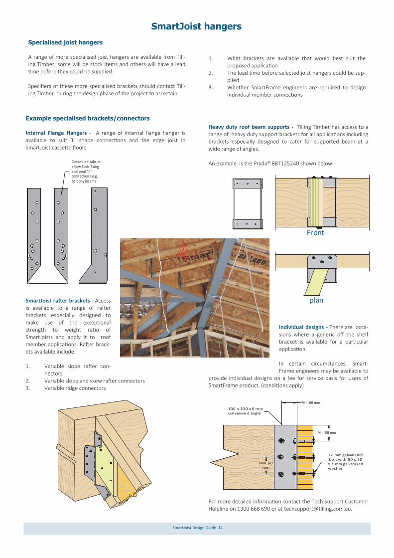
Example specialised brackets/connectors Internal Flange Hangers - A range of internal flange hanger is available to suit ‘L’ shape connections and the edge joist in SmartJoist cassette floors
SmartJoist rafter brackets - Access is available to a range of rafter brackets especially designed to make use of the exceptional strength to weight ratio of SmartJoists and apply it to roof member applications. Rafter brack-ets available include: 1. Variable slope rafter con-
nectors 2. Variable slope and skew rafter connectors 3. Variable ridge connectors
Heavy duty roof beam supports - Tilling Timber has access to a range of heavy duty support brackets for all applications including brackets especially designed to cater for supported beam at a wide range of angles. An example is the Pryda® BBT125240 shown below
Individual designs - There are occa-sions where a generic off the shelf bracket is available for a particular application. In certain circumstances, Smart-Frame engineers may be available to
provide individual designs on a fee for service basis for users of SmartFrame product. (conditions apply)
For more detailed information contact the Tech Support Customer Helpline on 1300 668 690 or at [email protected].
Con cealed tabs toallo w flush fixingand neat "L " conn ection s e.g.balc ony be ams
Specialised joist hangers A range of more specialised joist hangers are available from Till-ing Timber, some will be stock items and others will have a lead time before they could be supplied. Specifiers of these more specialised brackets should contact Till-ing Timber during the design phase of the project to ascertain:
1. What brackets are available that would best suit the
proposed application 2. The lead time before selected joist hangers could be sup-
plied 3. Whether SmartFrame engineers are required to design
individual member connections
plan
Front
12 mm galvans ied bo lt with 50 x 50 x 3 mm galvanised washer
100 x 10 0 x 6 mmGalvanise d angle
Min 60 mm
Min 50 mm
Min 60 mm
SmartJoist Design Guide 15
General connector installation details
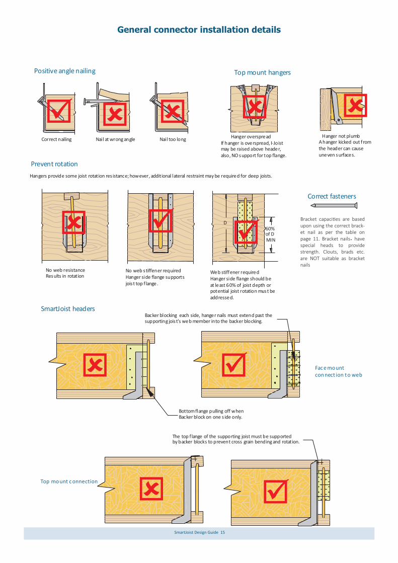
The top f lange of the supporting joist must be supportedby backer blocks to prevent cross grain bending and rotation.
Prevent rotation
60%of D MIN
Positive angle nailing Top mount hangers
Correct fasteners
SmartJoist headers
Top mount c onnection
Fac e mount con nect ion t o web
Hanger not plumbA hanger kicked out fromthe header can causeuneven surfaces.
Hanger overspreadIf hanger is overspread, I-Joistmay be raised above header, also, NO support for top flange.
Nail too longNail at wrong angleCorrect nailing
Web stiffener requiredHanger side flange should beat least 60% of joist depth orpotential joist rotation must beaddressed.
No web s tiffener requiredHanger side flange supportsjois t top f lange.
No web resistance Results in rotation
Bottom flange pulling off when Backer block on one s ide only.
Hangers provide some joist rotation res istance; however, additional lateral restraint may be required for deep joists.
Backer blocking each side, hanger nails must extend past thesupporting jois t's web member into the backer blocking.
DBracket capacities are based upon using the correct brack-et nail as per the table on page 11. Bracket nails have special heads to provide strength. Clouts, brads etc. are NOT suitable as bracket nails
SmartJoist Design Guide 16
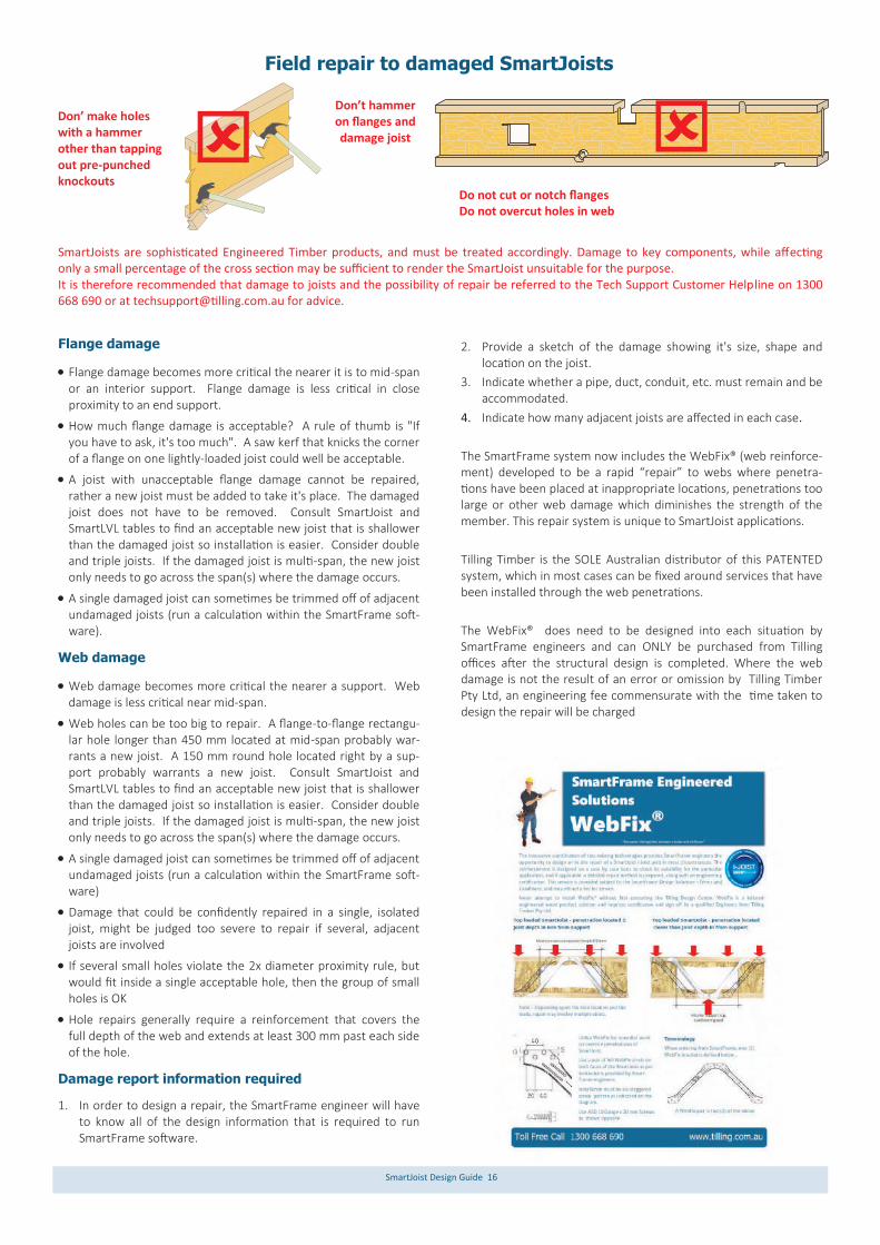
Flange damage
Flange damage becomes more critical the nearer it is to mid-span or an interior support. Flange damage is less critical in close proximity to an end support.
How much flange damage is acceptable? A rule of thumb is "If you have to ask, it's too much". A saw kerf that knicks the corner of a flange on one lightly-loaded joist could well be acceptable.
A joist with unacceptable flange damage cannot be repaired, rather a new joist must be added to take it's place. The damaged joist does not have to be removed. Consult SmartJoist and SmartLVL tables to find an acceptable new joist that is shallower than the damaged joist so installation is easier. Consider double and triple joists. If the damaged joist is multi-span, the new joist only needs to go across the span(s) where the damage occurs.
A single damaged joist can sometimes be trimmed off of adjacent undamaged joists (run a calculation within the SmartFrame soft-ware).
Web damage
Web damage becomes more critical the nearer a support. Web damage is less critical near mid-span.
Web holes can be too big to repair. A flange-to-flange rectangu-lar hole longer than 450 mm located at mid-span probably war-rants a new joist. A 150 mm round hole located right by a sup-port probably warrants a new joist. Consult SmartJoist and SmartLVL tables to find an acceptable new joist that is shallower than the damaged joist so installation is easier. Consider double and triple joists. If the damaged joist is multi-span, the new joist only needs to go across the span(s) where the damage occurs.
A single damaged joist can sometimes be trimmed off of adjacent undamaged joists (run a calculation within the SmartFrame soft-ware)
Damage that could be confidently repaired in a single, isolated joist, might be judged too severe to repair if several, adjacent joists are involved
If several small holes violate the 2x diameter proximity rule, but would fit inside a single acceptable hole, then the group of small holes is OK
Hole repairs generally require a reinforcement that covers the full depth of the web and extends at least 300 mm past each side of the hole.
Damage report information required
1. In order to design a repair, the SmartFrame engineer will have to know all of the design information that is required to run SmartFrame software.
2. Provide a sketch of the damage showing it's size, shape and location on the joist.
3. Indicate whether a pipe, duct, conduit, etc. must remain and be accommodated.
4. Indicate how many adjacent joists are affected in each case.
The SmartFrame system now includes the WebFix® (web reinforce-ment) developed to be a rapid “repair” to webs where penetra-tions have been placed at inappropriate locations, penetrations too large or other web damage which diminishes the strength of the member. This repair system is unique to SmartJoist applications.
Tilling Timber is the SOLE Australian distributor of this PATENTED system, which in most cases can be fixed around services that have been installed through the web penetrations.
The WebFix® does need to be designed into each situation by SmartFrame engineers and can ONLY be purchased from Tilling offices after the structural design is completed. Where the web damage is not the result of an error or omission by Tilling Timber Pty Ltd, an engineering fee commensurate with the time taken to design the repair will be charged
Don’ make holes with a hammer other than tapping out pre-punched knockouts
Don’t hammer on flanges and damage joist
Do not cut or notch flanges Do not overcut holes in web
SmartJoists are sophisticated Engineered Timber products, and must be treated accordingly. Damage to key components, while affecting only a small percentage of the cross section may be sufficient to render the SmartJoist unsuitable for the purpose. It is therefore recommended that damage to joists and the possibility of repair be referred to the Tech Support Customer Helpline on 1300 668 690 or at [email protected] for advice.
Field repair to damaged SmartJoists

SmartJoist Design Guide 17
Typical SmartJoist floor framing
Typical SmartJoist floor construction details
Sma rtJoistblo cking
pan el
Sma rtJoistrim joist
NOT E:Top plate w idth m ust be greaterthan width of flan ge rim joist +
30 m m (mi n bear ing length)
So lid blo ck all p osts from above to
bea ring be low.
19m m thic kSma rtRimrim board
Butt section s togetherat c entre o f lowersto rey stud.
2 la yers of19m m thic kSma rtRimRim board
Single/Upp er stor ey
Low er stor ey of tw o store y
Fix r imboa rd with1/3 .15 mm dia. x 65 nai l into top & bottom flan ges
Fix rimbo ard in to
top & bo ttom plates 30 mm in andat 4 5 deg angle with60 x 3.15 mm n ail @ 1 50mm ctrs
Fix b ottom platewith 90x/3 .15mmnai ls @ 1 50 crs intofloo ring
30
Bea rer
Jois ts
Loa d-beari ng wall
Sma ll secti on of bea rer ma terial placed on stu mps/p iers to sup port joists sup porting paralle lload -beari ng wall s.
Note: To achieve the necessary racking resistance through the floor diaphragm, it is important that the nailing provisions of the floor sheeting to the joists as de-scribed in AS 1684 (AS 1869 for particle board) be adopted to nail the floor sheeting to the Rim Joist or SmartRim in details F1-F3
Tem porary struts at 240 0 mm c entres . Nail stru ts at ea ch jois t with
2 o ff 3.15 x 65 mm n ails
Mul tiple m ember lam ination
Stan dardSma rtJoist
han gers
Rafter cuts
Mu ltipleSma rtJoists
Endblocking
optio ns
Sma rtJoist load bea ring ca ntilever s
SmartJois ts sup portin goffs et load bearin g walls
Sma rtJoist to steelcon nections
No n-load
bea ring can tilevers
Bric k ledge can tilevers
SmartJois t conn ectio n to w aler pl ates
F14 F26
F1
F2
F3
F4
F1 F2
F3
F4
F5
F5
F6
F7
F8
F9 F9A
F10
F11
F27
F21
F9B

SmartJoist Design Guide 18
Backer for claddingatta chment
Use double joists
under wall where
vertical loa d exce eds
29 KN/m
90 X 45 F5 Cripple ske w
nail ed to both
flanges with
3.1 5 x 65 nails.
2 mmLoa d beari ng wall
above must stack
ove r wall below
Sma rtJoist shall be designed
to support load be aring wall
above whe n not s tacked over
wal l below.
NOT E: Detail F7 with blocking pa nel is require d for bracing walls.
Sma rtJoist
blocking
Panel
Non Load bearing
wal l to a maximum
height of 2 400 mm
Sma rtJoist blocking
A
Bea ring.MIN.
70 mm
Section A-A
Nai l to backer block & jois t with 2 rows of
3.15 x 75 mm at 1 50
mm centre s and clinch
A
Backer block - nai l with 2 rows of
3.75 dia x 65 mm nails a t 150 centres
and clinch
1.5 x LL
Min F7 - Durable or
trea ted timber
(Uniform loads ONLY).
Sma rtJoist blocking
Sma rtJoists may be cantil evered up to 1 /3
of their ba ck span.
L
Exa mple: 3 600 mmExa mple 1 200 mm
L/3 MAX.
NOT E: Sma rtJoists
MUST be fully protected
from the weather
Uni form loads ONLY
Additional nails a t end the prevent rota tion90 - 190 mm joist - 6 nai ls200 - 290 mm jois t - 8 na ils
300 - 400 mm jois t -10 nails
Non Load bearing
wal l to a maximum
height of 2 400 mm
Typical SmartJoist floor construction details (cont’d)
Interior loading bearing and bracing walls
WARNING - Correct blocking for SmartJoists. Green timber shall not be used under any circumstance
Non load bearing cantilevers (balconies)
Example cantilever spans and minimum back spans for this detail are shown in the table on the next page
All blocking shall be carried out as per details F1-F3, with blocking to extend to both flanges and skew nailed with 3.15 Ф x 65 nails, one each side of top and bottom flange.
F6
F7 F8
F9
F9a
For cantilevered joists supporting load bearing walls see details C1-C4
1. Adjacent cantilevers joists
SmartJoist Design Guide 19
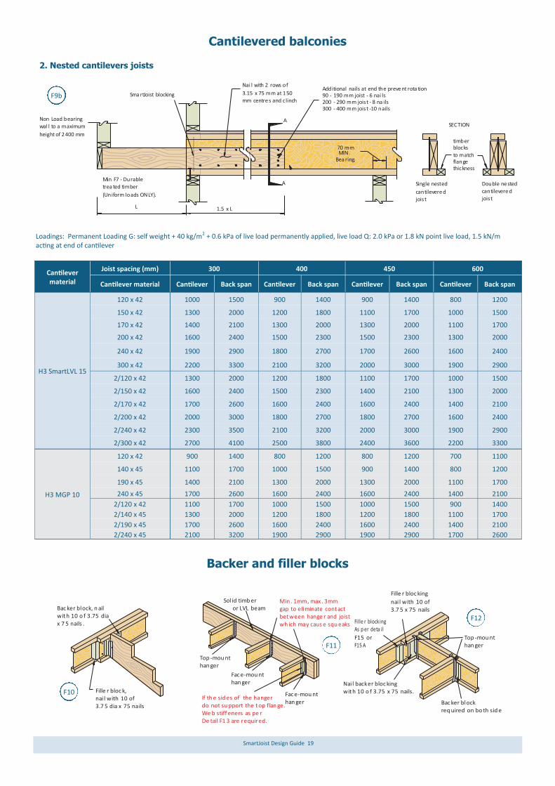
Cantilevered balconies
Cantilever material
Joist spacing (mm) 300 400 450 600
Cantilever material Cantilever Back span Cantilever Back span Cantilever Back span Cantilever Back span
H3 SmartLVL 15
120 x 42 1000 1500 900 1400 900 1400 800 1200
150 x 42 1300 2000 1200 1800 1100 1700 1000 1500
170 x 42 1400 2100 1300 2000 1300 2000 1100 1700
200 x 42 1600 2400 1500 2300 1500 2300 1300 2000
240 x 42 1900 2900 1800 2700 1700 2600 1600 2400
300 x 42 2200 3300 2100 3200 2000 3000 1900 2900
2/120 x 42 1300 2000 1200 1800 1100 1700 1000 1500
2/150 x 42 1600 2400 1500 2300 1400 2100 1300 2000
2/170 x 42 1700 2600 1600 2400 1600 2400 1400 2100
2/200 x 42 2000 3000 1800 2700 1800 2700 1600 2400
2/240 x 42 2300 3500 2100 3200 2000 3000 1900 2900
2/300 x 42 2700 4100 2500 3800 2400 3600 2200 3300
120 x 42 900 1400 800 1200 800 1200 700 1100
H3 MGP 10
140 x 45 1100 1700 1000 1500 900 1400 800 1200
190 x 45 1400 2100 1300 2000 1300 2000 1100 1700
240 x 45 1700 2600 1600 2400 1600 2400 1400 2100
2/120 x 42 1100 1700 1000 1500 1000 1500 900 1400
2/140 x 45 1300 2000 1200 1800 1200 1800 1100 1700
2/190 x 45 1700 2600 1600 2400 1600 2400 1400 2100
2/240 x 45 2100 3200 1900 2900 1900 2900 1700 2600
Loadings: Permanent Loading G: self weight + 40 kg/m2 + 0.6 kPa of live load permanently applied, live load Q: 2.0 kPa or 1.8 kN point live load, 1.5 kN/m acting at end of cantilever
Sma rtJoist blocking
A
Nai l with 2 rows of
3.15 x 75 mm at 150 mm centre s and clinch
A
1.5 x LL
Min F7 - Durable trea ted timber
(Uniform loads ONLY).
Non Load bearingwal l to a maximum
height of 2400 mm
70 mmMIN.
Bea ring.
Additional nails at end the preve nt rota tion90 - 190 mm joist - 6 nai ls200 - 290 mm jois t - 8 na ils300 - 400 mm jois t -10 nails
timberblocks to matchflange thickness
Single nested
cantilevere djois t
Double ne stedcantilevere djois t
SECTION
2. Nested cantilevers joists
Backer and filler blocks
Fille r bloc k,nai l with 10 of3.7 5 dia x 75 nails
Bac ker block, n ailwith 10 o f 3.75 dia x 7 5 nails .
Nai l backer bloc kingwith 10 o f 3.75 x 75 nails.
Bac ker blockreq uired on bo th sid e
Top -mou nthan ger
Fille r bloc king
nai l with 10 of3.7 5 x 75 nails
Fille r block ingAs p er deta il
F15 or F15 A
Sol id timb er or LVL beam
If th e sid es of the hanger do not su pport the top flan ge.We b stiff eners as pe r De tail F1 3 are required.
Fac e-mou nthan ger
Top -mou nthan ger
Min . 1mm, max . 3mmgap to eliminate contactbetween hange r and joistwh ich may caus e squ eaks
Fac e-mou nthan ger
F10
F11
F12
F9b

SmartJoist Design Guide 20
Backer and filler blocks (cont’d)
Recommended filler blocks and web stiffeners
NOTES: 1. Use plywood sheathing for web stiffener with face grain parallel to
long axis of the stiffener.
2. Filler blocks noted are for the general requirements of the details within this Design Guide.
3. Leave 3 mm gap between top of filler blocks and bottom of top flange.
SmartJoist code
Web stiffener material Recommended filler block stiffener nails
SJ20044 120 x 35 15 x 60 mm ply 4-3.15 x 65
SJ24040 140 x 35 15 x 60 mm ply 4-3.15 x 65
SJ24051 140 x 45 19 x 60 mm ply 4-3.15 x 65
SJ24070 150 x 58 LVL 2/15 x 60 mm ply 4-3.15 x 65
SJ24090 2/140 x 45 2/19 x 60 mm ply 5-3.15 x 65
SJ25570 170 x 58 LVL 2/15 x 60 mm ply 4-3.15 x 65
SJ30040 190 x 35 15 x 60 mm ply 4-3.15 x 65
SJ30051 190 x 45 19 x 60 mm ply 4-3.15 x 65
SJ30070 150 x 58 LVL 2/15 x 60 mm ply 4-3.15 x 65
SJ30090 2/190 x 42 LVL 2/19 x 60 mm ply 5-3.15 x 65
SP30095 2/190 x 42 LVL 2/21 X 60 mm
SmartRim 5-3.15 x 65
SJ36058 250 x 50 2/12 x 60 mm ply 5-3.15 x 65
SJ36090 2/240 x 45 2/19 x 60 mm ply 5-3.15 x 65
SJ40090 2/240 x 45 2/ 19 x 60 mm ply 5-3.15 x 65
F12a
F12b
F12c
F12 b.2F12 b.1
F12 b.3
50 ±
50 ±
50 ±
50 ± 2 ro ws of 3.7 5 x 75 nailsat 1 50 mm spac ing,clin ched
Small Gap( 3mm ± )
50 ±
50 ±
50 ±
50 ± 2 ro ws of 3.7 5 x 75 nailsat 1 50 mm spac ing,
clin ched
Small Gap ( 3mm ± )Small Gap( 3mm ± )
2 ro ws of 3.7 5 x 75 nailsat 1 50 mm spacin g,clin ched
Tigh t Fit50 ±
50 ±
50 ±
50 ±
50 ±
50 ±2 ro ws of 3.75 x 75 nail s at 15 0 mm spac ing eac h end (Offs et nai ls
fro m opp osite face b y 75 mm), c linche d
Small Gap( 3mm ± )
F12 b.4
2 ro ws of 3.7 5 x 75 nailsat 1 50 mm spac ing,
clin ched
2 ro ws of 3.7 5 x 75 nailsat 1 50 mm
spac ing,Clin ched
2 ro ws of 3.7 5 x 75 nailsat 1 50 mm spac ing,clin ched
For 2/51mm 2/70 mm 2/9 0mm & 3/SJs with 1/setd own jo ist attac hed
For 2/40mm & 2/4 4mm SJswith 1/setd own jo ist attac hed
Nail backer blocki ngwith 75 x 3 .15 mm nails.Refe r to tab le for no. of nail s requi red
Fac e mou ntjois t hanger
Fille r bloc kingas p er de tail F15 or F1 5a
Web stiffen ers req uired for
SJ4 0090 joists as per Deta il F13
Backer bloc kon both s ides
Small Gap
Face mount oruniversal hanger
Top mount or universal hanger
Setdown or change in level
Refer to detailF12b.3 or F12b.4
Refer todetail F12b.1
Refer to Detail F12b.2
Backer block
Fil ler block

SmartJoist Design Guide 21
Concentrated loads on SmartJoists
Multiple SmartJoist members (a) filler blocks
NOTE: 1. Web stiffeners are NOT required
at end bearing supports when span length are taken from the SmartJoist Design Guide, except where they are required to pre-vent rotation if the joist hanger dos not laterally restrain the top flange
2. Web stiffeners may be required at inner supports under concen-trated loads. Consult the appro-priate tables.
Small gap
( 3mm ± )
Nails, 4 off
3.15 x 65,
clinched
Tight fit50 mm ±
50 mm ±
3 mm min. gap
Tight Fi t
Concentrated load from GT,
TGT, lintel etc.
3 mm min. gap
Web stiffeners under concentrated loads are required as shown below for concentrated loads that exceed 6.5 kN ONLY.
F13
3mm gap
Con tinuo us fille r bloc k
3.75 x 75 n ails at 150 mmspac ing. (O ffset na ils from opp osite fa ce by 7 5 mm)
3mm gap m in.
3.7 5 x 75 nails at150 mm sp acing.
(Offs et nail s from opp osite fa ce by 7 5 mm)
Con tinuo us fille r bloc k
50 ±
50 ±
2 ro ws of 3.7 5x75n ailsat 1 50mm spac ingClin ched
50 ±
50 ±
2 ro ws of
3.7 5x75 n ailsat 1 50 mm spac ingClin ched
2 ro ws of 3.75x 75 nail s at 150 spacin g each end. (Offset nail s from opposite face by 75 mm),
clin ched
Small gap( 3m m ± )
Small gap( 3m m ± )
Min . 3 mm gap Min . 3 mm gap
For 2/70mm 2/90 mm & 3 /SJs(nai led from both sides)
For 2/40mm 2/44 mm & 2 /51mm
For 2/70mm 2/90 mm & 3/ SJs (na iled fro mboth side s)
For 2/40mm 2/44 mm & 2/ 51mm
Min . 20
Min . 30
Min . 20
Min . 20
Min . 75
2 ro ws of 3.7 5x75 n ails
at 1 50 mm spac ingClin ched
Min . 20
Min . 20
Min . 20
Min . 20
Min . 75
2 ro ws of 3.75x 75 nail s at 150 spacin g each end. (Offset nail s from opposite face by 75 mm), clin ched
2 ro ws of 3.75x 75 nail s at 150 spacin g each end. (Offset nail s from opposite face by 75 mm), clin ched
F15a
F15b
(b) SmartJoist Multi Joist clips (MJC)
Eit her 1 or 2 I-Clipsdepending upon
floo r load area
Max 200 mm spacing
2 ply SmartJoist supporting concentrated loads F15c
The SmartFrame MJC is Australia’s first backer and filler free solution to join multiple SmartJoist members
SmartJoist Applications - Characteristic Concentrated loads (kN)
No of MJC’s Max incoming Concentrated Load
4 16.4
8 24.6
SmartJoist Design Guide 22
UB , UC o rCha nnelSec tion
Min bearinglen gth 35 mm
Reb ate of12 m m Ma x
3-4 mm ga p betw eentop of web stiffene r
and top fla nge
We b stiff ener installedin c ontac t with botto m
flan ge as per de tail F12
Ade quate l ateral r estrain tor a lternatively, a 10 x 3 0 mm long type 17 s crew tolow er flange
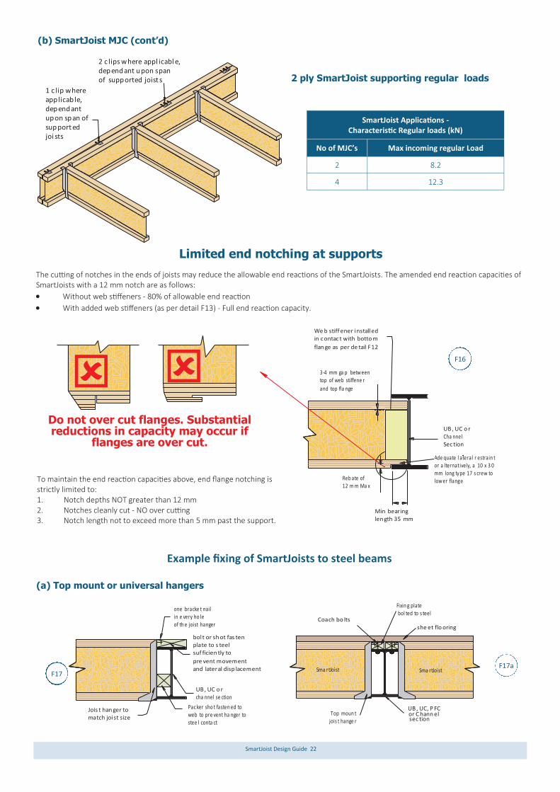
Limited end notching at supports
The cutting of notches in the ends of joists may reduce the allowable end reactions of the SmartJoists. The amended end reaction capacities of SmartJoists with a 12 mm notch are as follows:
Without web stiffeners - 80% of allowable end reaction
With added web stiffeners (as per detail F13) - Full end reaction capacity.
Do not over cut flanges. Substantial reductions in capacity may occur if
flanges are over cut.
To maintain the end reaction capacities above, end flange notching is strictly limited to: 1. Notch depths NOT greater than 12 mm 2. Notches cleanly cut - NO over cutting 3. Notch length not to exceed more than 5 mm past the support.
Example fixing of SmartJoists to steel beams
(a) Top mount or universal hangers
(b) SmartJoist MJC (cont’d)
2 ply SmartJoist supporting regular loads
she et flo oringCoach bo lts
Fixin g plate bol ted to s teel
or C hann elUB , UC, P FC
sec tion Top moun tjois t hange r
UB , UC o r cha nnel se ction
one bracke t nail in e very ho leof th e joist hanger
Jois t han ger to match joist size
Pac ker sho t fasten ed toweb to pre vent ha nger to stee l conta ct
bolt or sh ot fas tenplate to s teel suf ficien tly to
pre vent movementand lateral disp lacement Sma rtJoistSma rtJoist
F17
F16
F17a
SmartJoist Applications - Characteristic Regular loads (kN)
No of MJC’s Max incoming regular Load
2 8.2
4 12.3
1 c lip where app licab le, dependantupon span of support edjoi sts
2 c lips where appl icabl e,dependant upon spanof supported joist s

SmartJoist Design Guide 23
Example fixing of SmartJoists to steel beams
UB , UC
or C hanne l sec tion
Fixin g plate to eith er be bolted or s hot fas tened toto s teel pre vent ANY movementand latera l displa cemen t
Fac e-Mo unt jo ist han ger to match joist s ize.
Ske w nai l top f lange to fixing plate with2/3 .15mm dia x 65mm nails
Fixing plates: size de pende nt upo n ste el beam size s, bu t not less than 25 mm be aring onto s teel b eam.Nai l secu rely to packers
70x 35 or 70x4 5
vertical sof twood pac ker sho t fixedto th e stee l web
We ld the top-mount hange r (ste el top plate ) onto the top flangeof the UB , UC o r PFC steel beam
(Re fer to detai ls belo w)UB , UCor C hanne l sec tionTop -mou nt jois t hanger
to match joist s ize.
Min imum 3 mm, m aximu m 6mm
spa ce to el iminate conta ct betw eenhan ger and steel which m ay cau sesqu eaks.
30x 6 gauge bugle-heador w afer-h ead wo od scre ws
Plan View
Section A:A
Leg
size
20m mAAPac ker to pre vent joisthan ger toste el con tact
The welding of top mount SmartJoist hangers to common steel sections (UB, UC etc. must be carried out strictly as follows:
1. Supporting steel section must be thoroughly cleaned to remove black scale, rust, paint etc. 2. Clamp top flange of bracket hard up against steel section 3. Apply fillet weld to lap joint with the minimum weld length of 20 mm with a leg size at least the thickness of the metal hanger (see
diagram above) 4. Commence weld pool away from the hanger steel to ensure penetration into supporting steel prior to penetration into hanger tab 5. Finish connections with anti-corrosive paint to achieve appropriate corrosion resistance 6. It is essential that welding is conducted under the guidance of an experienced welder
Welding to steel sections (not suitable for universal hanger)
F17b F17c
20 m m (MAX)
web notch to bethe min ne cessaryfor c learan ce.
Min Bearin glength 45 m m
UB, UCor C hannel Section
We b stiff ener installe din c ontac t with botto m
flan ge as per de tail F1 2
D/2 (Max)5 - 6 mm ga p
Ade quate l ateral r estrain t or a ltenatively, 1/ No 10 x 30mm long type 17 s crew
as s hown.May be reb ated a s perdeta il F16
Tim ber pac ker,min imum o f 35 m mbea ring to steel and SmartJoist
Packer to b e secur ely
faste ned to steel b eam
UB
Stee l Beam
Sma rtJoist12 m mmax imum
reba te
Do n ot exce ed mo rethan 5 mm past su pport.
D
2 o f 3.15 x 65 mmskew nails, one ea ch side ,
2/3 up flan ge a m inimum of 3 0 mm f rom the end
(b) Rebated into steel beam
F18
F18a
Jois t hange r as pe rthis Design Guide
Fixin g plate s: size depend ent upo n Smar tJoist a nd stee l bea m sizes , but n ot less than 25 mm bear ingonto steel beam
70 mm ve rticalsof twood packer
at joist lo cationsho t naile d to ste el we b
Fille r bloc k dep th mu stfit all face mou nt nailsMin imum 35mm thic k
Ske w nai l top f lange to fixing plate with2/3 .15mm dia x 65mm nails
Fac e-Mo unt
jois t hanger to match joist s ize
Fixin g plate s: size depend ent upo n steel beam sizes,
but not les s than 2 5 mm bea ring on to stee l beam(Fix back to pac kers)
Ske w nai l top f lange to fixing plate with2/3 .15mm dia x 65mm nails 70x 35mm or 7 0x45mm
vertical s oftwo od packersho t fastened to the steel we b
(c) Face mounting to steel
F19
F19a

SmartJoist Design Guide 24
Example fixing of SmartJoists to steel beams (cont’d)
250 UC o r 310U C
Fixing plate fixe d toste el beam with bolts(As per e ng. sp ec)
Section AA
A
Ho rizontal pine in fro nt of vertic als310 UC - 70x45 mm M GP10250 UC - 70x35 mm M GP10
Fixin g plate
310 UC - 300x5 8mm LVL15250 UC - 240x4 2mm LVL15
AVertical p ine @ 450mm ctr against steel w eb310 UC - 70x45 mm M GP10250 UC - 70x45 mm M GP10
(c) Fixing to masonry walls
Masonry ancho rs to engineers design and install ed toman ufactu rer's reco mmen dations .
Bric k or mason ry wal l
SmartLVL or similarplate, de pth to appro xmatch joist dep th.
Fac e-mou nt oruniversal joist h ange r
Masonry ancho rs to engineers design and install ed toman ufactu rer's reco mmen dations .
Bric k or mason ry wal l
SmartLVL or similarplate
Top -mou nt oruniversal hange r
Plywood packe r
3.1 5x50 FH nai ls@ 1 50 ctrs into w all plate
30x 6 gau ge bu gle-he ador w afer- head wood screw s
F19b
F20 F20a
The tie-down needs of the structure are related to the applied wind loads and the effect of bracing walls either parallel or per-pendicular to the supporting member. Reference should be made to AS 1684 for further guidance on this issue. Floor systems are integral in the transfer of all vertical and hori-zontal loads to the footing system. Methods to transfer both up-lifts and bracing loads to the floor system will vary dependent upon: 1. Loads are applied into a structural element that is running
parallel to the bracing/tie-down panel 2. Loads are applied into a structural element that is running
perpendicular to the bracing/tie-down panel AS 1684 requires bracing to be approximately evenly distributed and provided in both directions as shown below. Care must be taken with tie down to resist bracing loads because the applied
load could be either up or down, whereas the wind uplift forces are always vertically up. Where the bracing walls are parallel to a floor joist, the joist in-volved must be designed to resist the applied forces imposed, over and above any gravity and normal live loads associated with the floor system The general details relating to the tie-down provisions of solid end section timber may be adopted for SmartJoists, except that under NO circumstances is it permitted to bolt through either the top or bottom flange, except when the joist is fully supported upon a wall plate or similar as shown below. Care must also be taken to en-sure that any bolts etc. drilled through solid timber joists do not compromise the structural integrity of that member. A conservative solution to bracing walls directly above parallel joists is to adopt a double joist at that location, with the tie down connection bolt running down between the two joists.
Tie down and bracing wall support details
Win d dire ction
Win d dire ction
Bracing walls parallel to joists
Bracing walls Perpendicular to joists

SmartJoist Design Guide 25
Seasoned timb erbloc king pi ece
Bra cing (tie down) wall M1 0 bolt with 42mm LVL1 5 timber br idging cleat to a chieve 6.1kN c haracteristic upl ift cap acityorM1 2 bolt with 58mm LVL1 5 timber br idging cleatto a chieve 8kN ch aracter istic upl ift cap acity
Sma rtJoistat 4 50 mmctr m ax.
Nai ls to loc ate bri dging c leataga inst top flange as sho wnRefe r to ta ble bel ow forNo of nails to ach ievethe require d dow nward cap acity
.
Sma rtLVL15 timbe r brid ging c leat. C leatsto b e placed no close rthan 1200 mm. Re fer to ta ble be low for timber brid ging cle at size
Brac ing (tie down) wall
M1 2 bolt
It is IMPORTANT that this be am is n ailed into jo ist han gers topre vent joists s pread ing un der lo ad
SmartLVL 15 timber brid ging c leat.Cle ats to be placed n o clos er than 120 0mm.
Ref er to table b elow for timber br idging cleat size
17mm (minimu m) F11 PlyMin of 17 0mm wide. Nail with 4 of f 4.5 x 75 nails
and clinch . Fit flush u nder top flange of SmartJo ist
SmartJois t
at 4 50mmctr max
Jois t hangers(bo th up and dow n) w ith
galvanise d timb er con necto r nailsinto web stiffen ers/joist we b & timberbrid ging c leat (R eferto table b elow for No of nai ls requ ired)
Do not drill through either flange of SmartJoists unless they are fully supported on wall plate or similar
Downward force capacities
Timber bridging size (DxB mm)
No of nails through
SmartJoist web to bridging
Characteristic capacity (kN)
1.2G + Wdn
90x42/58 SmartLVL 15 2 4.0
130x42/58 SmartLVL 15 3 4.9
170x42/58 SmartLVL 15 4 5.8
Timber bridging size (DxB mm)
Hanger code
No of hanger
nails into joist
No of hanger
nails into bridging
Characteristic uplift and
downward capacity (kN)
90x58 SmartLVL 15 FB5890 8 4 9.6
130X58 SmartLVL 15 FB58120 12 6 13.6
170X58 SmartLVL15 FB58170 20 10 20.0
F21
F21a
Tie down and bracing wall support details (cont’d)
Bracing walls between parallel joists
Bracing walls vertically above parallel joists
The tie-down and bracing of any structure is or critical im-portance to its robustness. While some general guidance on this topic is given in AS 1684 sections 8 and 9 including some specific examples, very little information is provided to designers where the bracing or tie down forces act within a floor diaphragm, or how to transfer the design loads specified in table 8.18 to sup-porting members.
Below are some examples that may be helpful to designers utilis-ing SmartJoist floor joists but these examples must in no way be a substitute for expert engineering advice from an experienced structural engineer. Any member, especially tall slender sections typical of floor joists experience significant reduction in strength at the location of a vertical hole. Typically a vertical hole is deemed to have an effect of 1.5 times the diameter of the hole.
Bra cing (tie down ) wall
M1 2 bolt at en d ofeac h pan el and inte rmed iately at Max at 1 200 mm cen tres
SmartLVLat 4 50 mmctr m ax.
Do uble joistsund er parallelbracing w all
15 m m de ep notc hing of d ouble joists ispermitte d ONL Y if a sin gle un -notc hed jo istis s tructu rally adequ atein this po sition
Do not drill through single members unless the whole member is re-analysed with a reduced cross
section at the hole location
F21c
Bracing (t ie dow n) wall
M1 2 bolt at en d ofeac h pan el and inte rmed iately at Max at 12 00 mm cen tres
SmartJois tat 4 50 mmctr max.
1 p iece o f Min 35 mm timb erhard again st bo th side s of b olt, 50 mm w asher bearin g onto bo th pie ces
Dou ble jo istsund er parallelbrac ing wa ll
40 mm high slo t inON E web onlyto a llow tighteningof nut
F21b

SmartJoist Design Guide 26
Cyc lone rod
Cyc lone rod, nu t and was her un der top plate
Flo or she eting
We b stiffen ersas p er deta il F30 a-c
Max distan ce from
cycl one rod to we bstiffener of 100 m m.
Load bearing w all
cyc lone strap
Cyc lone rod, nut and w ashe r und er plateSmartJois t
blo ckingpan el We b stiff eners requ ired
e ach s ide of ALL joists with cyclon e ties
Cyc lone strap
Cyc lone rod, nut and w ashe r und er low er p late
Equ al to c antile verspan but MIN o f
600 mm.
Can tileve rSpan
We b stiff eners requ ired e ach s ide of ALL
joists with cyclon e ties
90 x 45 M GP 1 0 plate und er joist
Cyclone strap capacities
Where the strap ends of the cyclone strap are wrapped around the wall plate or other timber member and are fixed with 4 of 3.15 Ø x 35 nails, the design capacity ØNj of 15.3 kN is applicable, re-gardless of the timber joint group. Tests have proven that bending the legs of cyclone straps around the timber increases the ulti-mate load capacity.
While double joists shown in the above diagram, it is only necessary when loads exceed the capacities of single joist cantilevers.
Cyclone rod tie down for cantilevered SmartJoist floors
Joist/beam connections supporting offset load bearing walls
Modern building designs frequently call for the upper storey of a two storey dwelling to be set back from the lower wall to allow sufficient light access to all areas of the building. Provided that the SmartJoists have been designed to support this offset load, no special provisions need to be made for their support EXCEPT in the following support conditions:
Maximum roof area supported (m2)
- based upon worst case of 40 mm flange width (conservative for wider flanged joists)
Joist supported on joist hanger RA1 Lower flange bearing RA2
Joist spacing (mm)
300 400 450 600 300 400 450 600 300 400 450 600 300 400 450 600
Joist span (mm)
Sheet Tile Sheet Tile
3500 21.7 15.0 12.8 8.2 9.6 6.7 5.7 3.6 6.9 6.4 6.2 5.3 3.1 2.9 2.8 2.4
4000 21.1 14.5 12.3 6.9 9.4 6.4 5.5 3.1 6.7 6.2 6.0 4.6 3.0 2.8 2.7 2.0
4500 20.5 13.9 11.7 5.7 9.1 6.2 5.2 2.5 6.6 6.0 5.7 3.9 2.9 2.7 2.5 1.7
5000 20.0 13.4 10.4 4.4 8.9 5.9 4.6 2.0 6.4 5.8 5.1 3.1 2.9 2.6 2.3 1.4
5500 19.4 12.1 9.1 3.2 8.6 5.4 4.1 1.4 6.3 5.3 4.6 2.4 2.8 2.4 2.0 1.1
UB, UCor C hann el sec tion
Bric k or mas onry wall
Jois t hanger to match joist s ize.
Load bearing w all
UB, UC orCha nnelSec tion
Reb ate of12 m m Ma x Min bear ing
len gth 38 mm
Load bea ring wall
CS1
RA1
RA2

SmartJoist Design Guide 27
Support for Concentrated loads - Joist/beam connection supporting offset load bearing walls
Vertical laminations may be achieved by adopting the procedures described in clause 2.3 of AS1684, however these procedures should be considered as the minimum requirements to achieve the desired effect.
Experience with SmartLVL beams indicates that this degree of fixing may not satisfactorily prevent cupping of individual components as a result of the ingress of moisture between laminates during con-struction. The suggested method of vertical lamination below pro-vides a greater level of fixity between individual components, and with the use of an elastomeric adhesive, also prevents moisture penetration between the laminates.
Multiple member laminating of top loaded beams (Symmetrical loading) The edges of the individual sections must be carefully aligned to each other so that the composite beam is flat, allowing the applied loads to be equally shared.
Depths up to and including 300 mm: 2 rows of nails as shown above at 300 mm centre
Depths in excess of 300 mm: 3 rows of nails as shown above at 300 mm centres.
Beams supporting SmartJoists – Multiple member laminations
Min of one M12 b olt eve ry 1200 mm ce ntres and no t less th an 3 bol ts per f iller bl ock sec tion, Min edge and e nd dista nce of 60 mm .
300 mm de epSma rtJoist
Stu ds or postssup porting Trunca ted Girder tru ss or othercon centrated roofload s
Skew nail 2 of 3.1 5 x 75 m m nail s throu gh to lo wer pl ate
70 x 35 F5 naile d to und erside of top f langeof a djacen t joists with3.1 5 x 60 nails
We b stiffen eras p er deta ilF13
90 x 45 F5 stru t unde rcon centrated load . Numb er of s truts to match numbe rof m ember s in jam b stud orpos t
Min bearin glength 58 m m
Reb ate of
12 m m Ma x
Stu d or p osts sup portin g trun catedgird er tru ss or other con centrated roof lo ads
Reb ate as per engineerin g spe cificatio n
UB ,UC or PFCsec tion
Soli d timbe r(Sm artLVL1 5 or similar )Reb ate as per
engineerin g spe cificatio n
UB , UC o rChannelSec tion
Face -moun t or un iversaljois t hange r to ma tch jois t size.
3 ro ws of 3 .75 dia x 40 m m nail sinto the we b-stiffe ner ea ch side
Fixin g plate s: size depend ent upo n steel beam sizes, b ut not l ess than 25 mm bear ing onto steel beam(Fix back to pac kers)
250 UB, U C or P FC Se ction
Use 10 / 4 0x3.75m m gal vanised nailsHan ger De sign Ca pacity Dea d + Live Load = 7.75kNWin d Up lift = 5 .6kN
30x 6 gauge bugle-heador w afer-h ead wo od scre ws
3 ro ws o f 3.75 dia x 4 0 mm nai ls into the web
stiffener ea ch side
70x 35mm or 70x4 5mmvertical sof twood packer
fixe d to the steel w eb
Bric k/maso nry wa ll
Concentrated loads from any source such as girder trusses MUST be transferred through the floor space WITHOUT adding extra vertical loads to the ends of the SmartJoist at its bearing support. Examples of transferring these loads are shown below RA3 in-
volves the use of inclined timber struts as shown in the detail op-posite. Struts must be a tight fit and at a minimum angle of 60º to the horizontal. RA4 uses a solid member in lieu of SmartJoist un-der large concentrated loads. RA5 involves a face fixing to blocked out steel beam.
RA3
RA4
RA5

SmartJoist Design Guide 28
Bead of elastomeric adhesive
Bead of elastomeric adhesive
Temporarywaterproofmembrane
300 mm spacing
D
Nails driven on alternate sides
300 mm spacing
Multiple member lamination of side loaded beams (Non– symmetrical loading)
50 mm M in
50 mm M in
50 mm M in
50 mm Min
55 mm diameterwas her as per table4.1 2 - AS 1720 .1
Combination 1 Combination 2 Combination 32 p ieces of 35 or 42 mm
3 p ieces of35 or 42 mm
1 p iece of 35 or 42 mm1 p iece of 58 or 75 mm
Nail spacing
Bo lt spacing
Stagger ro w of bolts
Maximum floor load width supported by either outside member (mm)
Combination (see details above)
3.75Ф x 90 mm nails 12 mm Ф bolts
2 rows at 300 ctrs 3 rows at 300 ctrs 2 rows at 600 ctrs 2 rows at 300 ctrs
Combination 1 3400 5100 7500 15000
Combination 2 2900 4000 5600 11000
Combination 3 2900 4000 4500 11000
Beams supporting SmartJoists – Multiple member laminations (Cont’d)
Notes:
1. Table values are for 40 kg/m2 floors.
2. The table values for nails may be doubled for nails at 150 mm centres, and tripled for nails at 100 mm centres
LB2
LB1

SmartJoist Design Guide 29
3. The nail schedules shown apply to both sides of a three (3) piece beam
4. Bolts are to be grade 4.6 commercial bolts conforming to AS 1111. Bolt holes are to be a maximum of 13 mm diameter and are to be locat-ed NOT less than 50 mm from either edge.
5. All bolts shall be fitted with a washer at each end, of a size NOT less than that given in AS 1720.1 table 4.11.
How to use the maximum uniform side load table
Example: see diagram opposite Beam of 2 SmartLVL loaded on both side (Combination 1) FLW 1 = 2800 mm, FLW 2 = 2300 mm Total FLW = 2800 + 2300 = 5100 mm. 1. Use SmartFrame software or SmartLVL safe load tables to size the two member
section to support the FLW of 5100 mm. 2. Choose the larger of the side FLW's carried by the beam, in this case 2800 mm. 3. Enter the table at the "Combination 1" row and scan across to a table value greater
than 2800 mm. The first value in the row at 3600 mm is greater than the 2800 mm required.
4. Thus adopt 2 rows of 3.75Ф x 90 mm nails at 300 mm centres
Floor load width 1
= 2800 mm
Floor load width 2
= 2300 mm
Multiple member lamination of side loaded beams (Non– symmetrical loading) (cont’d)
SmartJoists can be “rafter cut” but only within the limitation shown below.
Rafter cuts are limited to:
1. 115 mm MINIMUM end height
2. MINIMUM Roof Slopes of 1 in 2 (approximately 26.50),
and
3. Must be blocked at the end to prevent rotation of the joist.
Joists without reinforcement are limited to design shear and end reactions up to 6.5 kN Ply reinforcement can be added to joists with rafter cuts to increase the shear and end reaction capacity of the joist. The detail below shows the proper installation of the reinforcement. With the reinforcement added, the end reaction and shear capacity increase to 12.7 kN. Duration of load increases are permitted as per AS1720.1.
Rafter cuts for SmartJoist floor joists
Oblique connection options
600 mm
2
1 M IN
19 mm F1 1 Ply or SmartRim. Install rein force ment to both side s of jo ist us ingadh esive meet ing AS/NZS 4 364:1 996 and nail u sing 1 4 of 3 .75 x 75 mm even ly spaced as show n. Al ternate nailing fro meac h side and c linch.
Blo cking
90 mmMin bearing
Top flange mus t bebraced ei ther b y she eting or 100 x 50for lateral stabi lity.
115 mm M IN
75 x 50 x 5 Unequ al Angl e150 mm lo ng supp ort, lon gLeg vertical - See d etail
SmartLVL beare r/wal ing plate
Skew nail to p flange with3.15 x 65 m m nail tobea rer/wa ling pla te
Fix SmartJ oist to angle
plate with a 10 x 30 mmlon g type 17 co unter - sunk scre w.
Min thickness o f
bea rer/wa ling pla te42 m m
Fix a ngle pl ate to b eareror w aling p late wi th6 N o 12 x 35 mm lon gType 17 He xagona l
hea d screw s.
Notch bo ttom c hord
of Sm artJoi st 55x5 mm for flush finish
Min distance from bo th ed ges 10 mm
50mmmin imum
6 o f 7.0 mm d ia hole s
5.0 mm d ia hole c ounte rsunk to und erside
20
Fix SmartJ oist to LVSIA anglewith 3 @ No. 1 0 x 30 mm Typ e 17, countersun k screw s
Notch bo ttom c hord of SmartJois t55x 5 mm for flu sh fin ish
Fix angle plate to beareror w aling plate with12 @ No. 12 x 3 5 mm longTyp e 17 h exago nal he ad sc rews
75 x 50 x 5 unequ al angle300 mm lo ng supp ort, lon gleg vertical - See d etail
Min thickness
of b earer/walin gplate 42 mm
3.7 5 x 75 nails at
300 mm s pacing.As p er de tail F1 5/F15 A
Tigh t fit c ontinu ous f iller
as p er de tail F1 5/F15 A
150
75
50 mm minimu m
12 o f 7.0 m m
d ia hole s5.0 mm d ia hole c ounte rsunk to und erside
300
75
Min distance from bo th ed ges 10 mm
20
Fix top ch ord to supp ortwith 2/75x3 .05mm nails per joist
F26
F27 F28
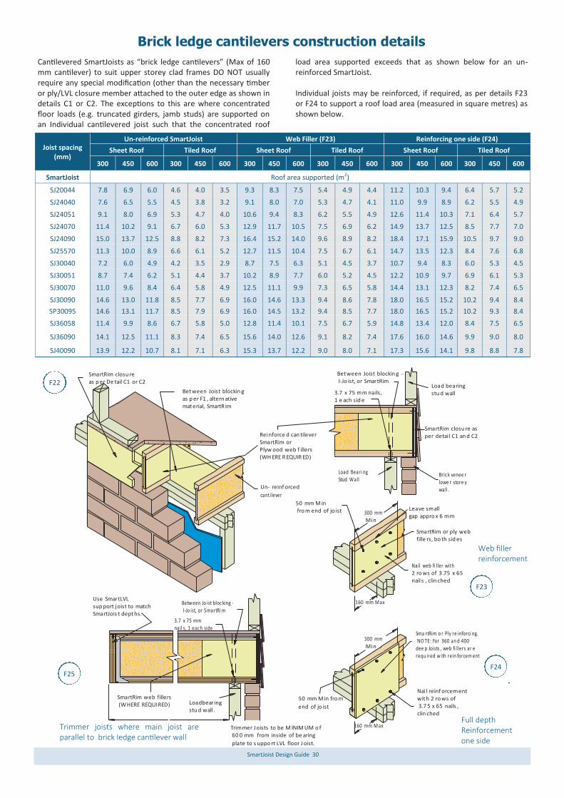
SmartJoist Design Guide 30
Brick ledge cantilevers construction details
Cantilevered SmartJoists as “brick ledge cantilevers” (Max of 160 mm cantilever) to suit upper storey clad frames DO NOT usually require any special modification (other than the necessary timber or ply/LVL closure member attached to the outer edge as shown in details C1 or C2. The exceptions to this are where concentrated floor loads (e.g. truncated girders, jamb studs) are supported on an Individual cantilevered joist such that the concentrated roof
load area supported exceeds that as shown below for an un-reinforced SmartJoist. Individual joists may be reinforced, if required, as per details F23 or F24 to support a roof load area (measured in square metres) as shown below.
Un-reinforced SmartJoist Web Filler (F23) Reinforcing one side (F24) Joist spacing
(mm) Sheet Roof Tiled Roof Sheet Roof Tiled Roof Sheet Roof Tiled Roof
300 450 600 300 450 600 300 450 600 300 450 600 300 450 600 300 450 600
SmartJoist Roof area supported (m2)
SJ20044 7.8 6.9 6.0 4.6 4.0 3.5 9.3 8.3 7.5 5.4 4.9 4.4 11.2 10.3 9.4 6.4 5.7 5.2
SJ24040 7.6 6.5 5.5 4.5 3.8 3.2 9.1 8.0 7.0 5.3 4.7 4.1 11.0 9.9 8.9 6.2 5.5 4.9
SJ24051 9.1 8.0 6.9 5.3 4.7 4.0 10.6 9.4 8.3 6.2 5.5 4.9 12.6 11.4 10.3 7.1 6.4 5.7
SJ24070 11.4 10.2 9.1 6.7 6.0 5.3 12.9 11.7 10.5 7.5 6.9 6.2 14.9 13.7 12.5 8.5 7.7 7.0
SJ24090 15.0 13.7 12.5 8.8 8.2 7.3 16.4 15.2 14.0 9.6 8.9 8.2 18.4 17.1 15.9 10.5 9.7 9.0
SJ25570 11.3 10.0 8.9 6.6 6.1 5.2 12.7 11.5 10.4 7.5 6.7 6.1 14.7 13.5 12.3 8.4 7.6 6.8
SJ30040 7.2 6.0 4.9 4.2 3.5 2.9 8.7 7.5 6.3 5.1 4.5 3.7 10.7 9.4 8.3 6.0 5.3 4.5
SJ30051 8.7 7.4 6.2 5.1 4.4 3.7 10.2 8.9 7.7 6.0 5.2 4.5 12.2 10.9 9.7 6.9 6.1 5.3
SJ30070 11.0 9.6 8.4 6.4 5.8 4.9 12.5 11.1 9.9 7.3 6.5 5.8 14.4 13.1 12.3 8.2 7.4 6.5
SJ30090 14.6 13.0 11.8 8.5 7.7 6.9 16.0 14.6 13.3 9.4 8.6 7.8 18.0 16.5 15.2 10.2 9.4 8.4
SP30095 14.6 13.1 11.7 8.5 7.9 6.9 16.0 14.5 13.2 9.4 8.5 7.7 18.0 16.5 15.2 10.2 9.3 8.4
SJ36058 11.4 9.9 8.6 6.7 5.8 5.0 12.8 11.4 10.1 7.5 6.7 5.9 14.8 13.4 12.0 8.4 7.5 6.5
SJ36090 14.1 12.5 11.1 8.3 7.4 6.5 15.6 14.0 12.6 9.1 8.2 7.4 17.6 16.0 14.6 9.9 9.0 8.0
SJ40090 13.9 12.2 10.7 8.1 7.1 6.3 15.3 13.7 12.2 9.0 8.0 7.1 17.3 15.6 14.1 9.8 8.8 7.8
Nai l reinf orcement with 2 ro ws of 3.7 5 x 65 nails ,clin ched
300 mm Min
160 mm M ax
50 mm M in fro m
end of jo ist
Leave smallgap appro x 6 mm
300 mm Min
SmartRim or ply webfille rs, bo th sid es
160 mm M ax
50 mm M in fro m end of jo ist
SmartRim closu reas p er De tail C1 or C2
Between Joist blockin gas p er F1 , altern ativematerial, SmartR im
Reinforce d can tileverSmartRim orPlyw ood web f illers(WH ERE R EQUIR ED)
3.7 x 75 mm nails,1 e ach sid e
Load Beari ngStud Wall
Between Joist blockin g - I-Jo ist, or SmartRim
Load bearingstu d wall
SmartRim closu re asper detai l C1 an d C2
Bric k venee rlowe r store ywall .
Nail web fi ller with 2 ro ws of 3.75 x 65nails , clin ched
SmartRim web fillers (WHERE REQUIRED) Loadbearing
stu d wall .
Trimmer J oists to be M INIM UM o f 60 0 mm from inside of be aring
plate to s uppo rt LVL floor J oist.
Use SmartLVLsup port joist to matchSmartJois t depths.
Betw een Jo ist bloc king - I-Jo ist, or SmartRi m
3.7 x 75 mm nail s, 1 eac h side
Sma rtRim o r Ply re inforci ng. NO TE: For 360 an d 400 dee p Joists , web fi llers ar e requ ired w ith rein forcem ent
Un- reinf orced
cantilever
F22
F23
F24 F25
Web filler reinforcement
Trimmer joists where main joist are parallel to brick ledge cantilever wall
Full depth Reinforcement one side

SmartJoist Design Guide 31
Don’t make holes with hammer
other than pre-punched
knockouts
Don’t hammer on flanges and damage joint Do not cut or notch flanges
Do not over cut holes in web
SmartJoist hole and duct charts
Min imum distancefro m hole chart
wid th 'w 'No te 3
wid th 'w ' see note 7
A 4 0 mm dia ho le may be cut anyw here in the web
De pth 'D '
Do not cu t hole s larger than 40 mm dia with in thecan tileve r
Min imum distance fro m hole chart
Note: The most accurate method to design the allowable web penetration size and distance from support for SmartJoists is to use the Smart-Frame software. The table below will give conservative results in some instances. Also, advice on hole size and location may be obtained by contacting the Tech Support Customer Helpline on 1300 668 690 or at [email protected].
Assumed loading (DL = 62 kg/m2, FLL = 2 kPa, FPL = 1.8 kN)
Joist code Joist span*
(mm)
Circular/square holes Rectangular holes Joist
spacing (mm)
Hole diameter/square hole width (mm) Depth x wdth (mm)
75 100 125 150 175 200 225 250 125x150 150x300 175x350 200x400
Minimum distance from any support to the centre of the hole (mm)
SJ20044
600-999
300 to
600
300 300 ns ns ns ns ns ns ns ns ns ns
1000-1499 300 300 ns ns ns ns ns ns ns ns ns ns
1500-1999 300 300 ns ns ns ns ns ns ns ns ns ns
2000-2499 300 600 ns ns ns ns ns ns ns ns ns ns
2500-2999 300 800 ns ns ns ns ns ns ns ns ns ns
3000-3300 300 900 ns ns ns ns ns ns ns ns ns ns
SJ24040
600-999
300 to
600
300 300 300 ns ns ns ns ns ns ns ns ns
1000-1499 300 300 300 ns ns ns ns ns ns ns ns ns
1500-1999 300 300 300 Span/2 ns ns ns ns 750 Span/2 ns ns
2000-2499 300 300 300 Span/2 ns ns ns ns 1000 Span/2 ns ns
2500-2999 300 300 500 Span/2 ns ns ns ns Span/2 Span/2 ns ns
3000-3500 300 300 800 Span/2 ns ns ns ns Span/2 Span/2 ns ns
SJ24051
600-999
300 to
600
300 300 300 ns ns ns ns ns ns ns ns ns
1000-1499 300 300 300 ns ns ns ns ns ns ns ns ns
1500-1999 300 300 300 Span/2 ns ns ns ns 750 Span/2 ns ns
2000-2499 300 300 300 Span/2 ns ns ns ns 1000 Span/2 ns ns
2500-2999 300 300 500 Span/2 ns ns ns ns Span/2 Span/2 ns ns
3000-3499 300 300 800 Span/2 ns ns ns ns Span/2 Span/2 ns ns
3500-3800 300 300 1000 Span/2 ns ns ns ns Span/2 Span/2 ns ns
SJ24070
600-999
300 to
600
300 300 300 ns ns ns ns ns ns ns ns ns
1000-1499 300 300 300 ns ns ns ns ns 300 ns ns ns
1500-1999 300 300 300 Span/2 ns ns ns ns 600 Span/2 ns ns
2000-2499 300 300 300 Span/2 ns ns ns ns 900 Span/2 ns ns
2500-2999 300 300 500 Span/2 ns ns ns ns 1250 Span/2 ns ns
3000-3499 300 300 800 Span/2 ns ns ns ns 1500 Span/2 ns ns
3500-3999 300 300 1000 Span/2 ns ns ns ns Span/2 Span/2 ns ns
4000-4100 300 450 1100 Span/2 ns ns ns ns Span/2 Span/2 ns ns
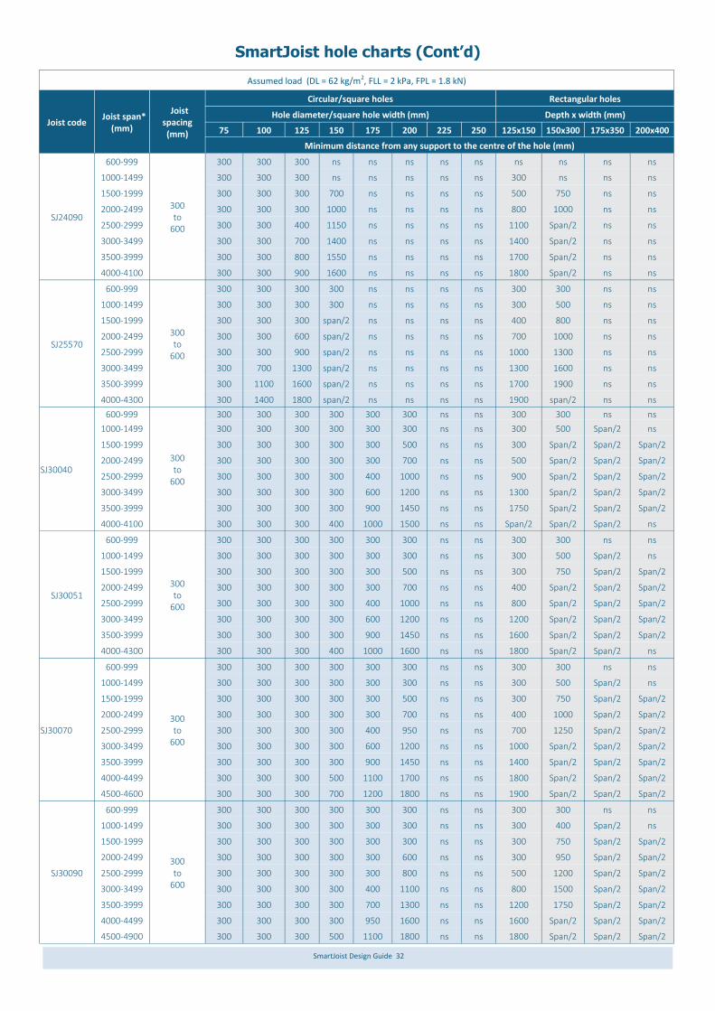
SmartJoist Design Guide 32
SmartJoist hole charts (Cont’d)
Assumed load (DL = 62 kg/m2, FLL = 2 kPa, FPL = 1.8 kN)
Joist code Joist span*
(mm)
Joist spacing (mm)
Circular/square holes Rectangular holes
Hole diameter/square hole width (mm) Depth x width (mm)
75 100 125 150 175 200 225 250 125x150 150x300 175x350 200x400
Minimum distance from any support to the centre of the hole (mm)
SJ24090
600-999
300 to
600
300 300 300 ns ns ns ns ns ns ns ns ns
1000-1499 300 300 300 ns ns ns ns ns 300 ns ns ns
1500-1999 300 300 300 700 ns ns ns ns 500 750 ns ns
2000-2499 300 300 300 1000 ns ns ns ns 800 1000 ns ns
2500-2999 300 300 400 1150 ns ns ns ns 1100 Span/2 ns ns
3000-3499 300 300 700 1400 ns ns ns ns 1400 Span/2 ns ns
3500-3999 300 300 800 1550 ns ns ns ns 1700 Span/2 ns ns
4000-4100 300 300 900 1600 ns ns ns ns 1800 Span/2 ns ns
SJ25570
600-999
300 to
600
300 300 300 300 ns ns ns ns 300 300 ns ns
1000-1499 300 300 300 300 ns ns ns ns 300 500 ns ns
1500-1999 300 300 300 span/2 ns ns ns ns 400 800 ns ns
2000-2499 300 300 600 span/2 ns ns ns ns 700 1000 ns ns
2500-2999 300 300 900 span/2 ns ns ns ns 1000 1300 ns ns
3000-3499 300 700 1300 span/2 ns ns ns ns 1300 1600 ns ns
3500-3999 300 1100 1600 span/2 ns ns ns ns 1700 1900 ns ns
4000-4300 300 1400 1800 span/2 ns ns ns ns 1900 span/2 ns ns
SJ30040
600-999 300 300 300 300 300 300 ns ns 300 300 ns ns
300 to
600
1000-1499 300 300 300 300 300 300 ns ns 300 500 Span/2 ns
1500-1999 300 300 300 300 300 500 ns ns 300 Span/2 Span/2 Span/2
2000-2499 300 300 300 300 300 700 ns ns 500 Span/2 Span/2 Span/2
2500-2999 300 300 300 300 400 1000 ns ns 900 Span/2 Span/2 Span/2
3000-3499 300 300 300 300 600 1200 ns ns 1300 Span/2 Span/2 Span/2
3500-3999 300 300 300 300 900 1450 ns ns 1750 Span/2 Span/2 Span/2
4000-4100 300 300 300 400 1000 1500 ns ns Span/2 Span/2 Span/2 ns
SJ30051
600-999
300 to
600
300 300 300 300 300 300 ns ns 300 300 ns ns
1000-1499 300 300 300 300 300 300 ns ns 300 500 Span/2 ns
1500-1999 300 300 300 300 300 500 ns ns 300 750 Span/2 Span/2
2000-2499 300 300 300 300 300 700 ns ns 400 Span/2 Span/2 Span/2
2500-2999 300 300 300 300 400 1000 ns ns 800 Span/2 Span/2 Span/2
3000-3499 300 300 300 300 600 1200 ns ns 1200 Span/2 Span/2 Span/2
3500-3999 300 300 300 300 900 1450 ns ns 1600 Span/2 Span/2 Span/2
4000-4300 300 300 300 400 1000 1600 ns ns 1800 Span/2 Span/2 ns
SJ30070
600-999
300 to
600
300 300 300 300 300 300 ns ns 300 300 ns ns
1000-1499 300 300 300 300 300 300 ns ns 300 500 Span/2 ns
1500-1999 300 300 300 300 300 500 ns ns 300 750 Span/2 Span/2
2000-2499 300 300 300 300 300 700 ns ns 400 1000 Span/2 Span/2
2500-2999 300 300 300 300 400 950 ns ns 700 1250 Span/2 Span/2
3000-3499 300 300 300 300 600 1200 ns ns 1000 Span/2 Span/2 Span/2
3500-3999 300 300 300 300 900 1450 ns ns 1400 Span/2 Span/2 Span/2
4000-4499 300 300 300 500 1100 1700 ns ns 1800 Span/2 Span/2 Span/2
4500-4600 300 300 300 700 1200 1800 ns ns 1900 Span/2 Span/2 Span/2
SJ30090
600-999
300 to
600
300 300 300 300 300 300 ns ns 300 300 ns ns
1000-1499 300 300 300 300 300 300 ns ns 300 400 Span/2 ns
1500-1999 300 300 300 300 300 300 ns ns 300 750 Span/2 Span/2
2000-2499 300 300 300 300 300 600 ns ns 300 950 Span/2 Span/2
2500-2999 300 300 300 300 300 800 ns ns 500 1200 Span/2 Span/2
3000-3499 300 300 300 300 400 1100 ns ns 800 1500 Span/2 Span/2
3500-3999 300 300 300 300 700 1300 ns ns 1200 1750 Span/2 Span/2
4000-4499 300 300 300 300 950 1600 ns ns 1600 Span/2 Span/2 Span/2
4500-4900 300 300 300 500 1100 1800 ns ns 1800 Span/2 Span/2 Span/2

SmartJoist Design Guide 33
Notes: 1. The hole chart is generated for single span joists with a maximum floor dead load of 62 kg/m2 with no wall or roof loads. It therefore does not apply for joists
supporting either parallel or perpendicular load bearing walls. These scenarios can be analysed by using the appropriate model within the SmartFrame soft-ware. Help can be obtained for continuous spans by contacting the Tech Support Helpline on 1300 668 690 or at [email protected]
2. Hole locations are suitable for joist spacings up to 600 mm centres. Holes may be permitted closer to supports for some member when spacings of 450 or 300 mm are used
3. The clear distance between holes must equal or exceed twice the diameter of the largest hole, or twice the longest side of a rectangular hole and no more than 3 holes in excess of 75 mm are allowed in any span
4. Do not cut or damage flanges under any circumstances 5. Except as noted in 1 and 2 above, a 40 mm hole at a minimum of 450 mm centres is allowed to be drilled anywhere in the web EXCEPT in cantilevered spans 6. If possible, holes in web should be positioned mid height, minimum edge clearance from any flange is 6 mm A group of round holes at approximately the
same location shall be permitted if they meet the requirements for a single round hole circumscribed around them.
Assumed load (DL = 62 kg/m2, FLL = 2 kPa, FPL = 1.8 kN)
Joist code Joist span
(mm)
Joist* spacing (mm)
Circular/square holes Rectangular holes
Hole diameter/square hole width (mm) Depth x width (mm)
75 100 125 150 175 200 225 250 125x150 150x300 175x350 200x400
Minimum distance from any support to the centre of the hole (mm)
SP30095
600-999
300 to 600
300 300 300 300 300 300 ns ns 300 300 300 300
1000-1499 300 300 300 300 300 300 ns ns 300 300 400 400
1500-1999 300 300 300 300 300 400 ns ns 300 500 700 700
2000-2499 300 300 300 400 600 700 ns ns 300 800 900 1000
2500-2999 300 300 300 700 900 1000 ns ns 300 1000 1200 span/2
3000-3499 300 300 400 1000 1200 1300 ns ns 600 1300 1500 span/2
3500-3999 300 300 700 1300 1500 1600 ns ns 1000 1600 1700 span/2
4000-4499 300 300 1100 1600 1800 1900 ns ns 1300 1900 2000 span/2
4500-4999 300 300 1500 2000 2200 2200 ns ns 1700 2200 2300 span/2
5000-5499 300 300 1900 2300 2500 span/2 ns ns 2100 span/2 span/2 span/2
SJ36058
1000-1499 300 300 300 300 300 300 300 300 300 300 400 ns
300 to 600
1500-1999 300 300 300 300 300 300 300 400 300 300 700 span/2
2000-2499 300 300 300 300 300 300 300 700 300 550 900 span/2
2500-2999 300 300 300 300 300 300 400 900 300 850 1200 span/2
3000-3499 300 300 300 300 300 300 650 1200 300 1200 1500 span/2
3500-3999 300 300 300 300 300 400 900 1400 300 1500 1750 span/2
4000-4499 300 300 300 300 300 600 1100 1700 300 1800 span/2 span/2
4500-5000 300 300 300 300 300 800 1400 1900 300 2200 span/2 span/2
SJ36090
600-999
300 to
600
300 300 300 300 300 300 300 300 300 300 ns ns
1000-1499 300 300 300 300 300 300 300 300 300 300 300 ns
1500-1999 300 300 300 300 300 300 300 300 300 300 450 700
2000-2499 300 300 300 300 300 300 300 400 300 300 750 1000
2500-2999 300 300 300 300 300 300 300 650 300 450 1000 1250
3000-3499 300 300 300 300 300 300 300 900 300 800 1300 1500
3500-3999 300 300 300 300 300 300 500 1150 300 1100 1600 span/2
4000-4499 300 300 300 300 300 300 750 1400 300 1450 1900 span/2
4500-4999 300 300 300 300 300 400 1000 1650 300 1800 2200 span/2
5000-5400 300 300 300 300 300 600 1200 1800 300 2100 2500 span/2
SJ40090
600-999
300 to 600
300 300 300 300 300 300 300 300 300 300 ns ns
1000-1499 300 300 300 300 300 300 300 300 300 300 300 ns
1500-1999 300 300 300 300 300 300 300 300 300 300 300 400
2000-2499 300 300 300 300 300 300 300 300 300 300 300 600
2500-2999 300 300 300 300 300 300 300 300 300 300 300 900
3000-3499 300 300 300 300 300 300 300 300 300 300 600 1200
3500-3999 300 300 300 300 300 300 300 400 300 300 1000 1500
4000-4499 300 300 300 300 300 300 300 600 300 300 1300 1800
4500-4999 300 300 300 300 300 300 300 800 300 500 1700 2100
5000-5499 300 300 300 300 300 300 400 900 300 1000 2000 2500
5500-5700 300 300 300 300 300 300 500 1100 300 1200 2200 2750
SmartJoist hole charts (Cont’d)

SmartJoist Design Guide 34
Opening width
Trimmer span
Joist span
Truncated joist span
Trimmer span
Openings within SmartFrame floors
The tables below are for trimmer members of SmartJoists and LVL. Other SmartFrame engi-neered timber products may also be used for this member, the designs for each of these other material types can be simply calculated by using the SmartFrame software or by contacting the Tech Support Customer Helpline on 1300 668 690 or at [email protected].
Trimmer
Trimmer
Truncated joists supported by trimmer
Opening trimmer
Floor live load 1.5 kPa
Trimmer Joists
Trimming joists at floor opening often support the loads from stair string-ers, as well as the concentrated load from the trimmer. The table below has been set up to allow a load from stairs equally supported from the floor below (or above) and the trimmer joists. In many cases this will pro-vide a conservative result. Alternative designs can be readily obtained by using the SmartFrame software or by contacting the Tech Support Cus-tomer Helpline on 1300 668 690 or at [email protected]
Floor live load 1.5 kPa
Floor live load 1.5 kPa
Sm
art
Jo
ists
S
ma
rtLV
L 1
5
Maximum trimming joist span (m) SmartFrame engineered
timber
Opening width 900 (mm) Opening width 1800 (mm) Opening width 2700 (mm)
Trimmer span (mm) Trimmer span (mm) Trimmer span (mm)
2 3 4 5 2 3 4 5 2 3 4 5
SJ20044 3300 3100 2800 2600 3400 3200 3100 3000 3700 3600 3600 3500
SJ24040 3700 3400 3200 3000 3600 3400 3100 3000 4000 3800 3700 3700
SJ24051 3900 3600 3400 3200 3800 3600 3400 3300 4100 4000 3900 3800
SJ24070 4200 3900 3700 3500 4100 3800 3600 3500 4400 4200 4000 4000
SJ24090 4500 4100 3900 3700 4300 4000 3800 3600 4500 4300 4200 4000
SJ25570 4800 4500 4200 4000 4600 4300 4100 3900 4800 4600 4400 4300
SJ30040 4300 4000 3700 3500 4100 3900 3700 3500 4400 4200 4100 3900
SJ30051 4500 4200 3900 3700 4300 4000 3800 3700 4600 4400 4200 4100
SJ30070 4900 4500 4200 4000 4600 4300 4100 3900 4800 4600 4400 4300
SJ30090 5100 4800 4500 4200 4900 4500 4300 4100 5100 4700 4500 4400
SP30095 5700 5500 5100 4900 5500 5100 4800 4600 5500 5200 5000 4800
SJ36058 5300 4900 4700 4400 5000 4600 4400 4200 5200 4800 4600 4400
SJ36090 5700 5300 5000 4800 5400 5000 4800 4400 5500 5100 4900 4700
SJ40090 6100 5800 5500 5200 5800 5300 5000 4800 5800 5400 5100 4900
200x42 3600 3200 2900 2700 3600 3300 3100 3000 4000 3900 3700 3600
240x42 4200 3800 3500 3300 4100 3800 3600 3400 4400 4200 4000 3900
300x42 5100 4600 4300 4100 4800 4400 4100 4000 5000 4700 4500 4300
360x42 6000 5400 5100 4800 5500 5000 4700 4500 5600 5200 5000 4800
200x58 3900 3600 3300 3000 3900 3600 3400 3200 4200 4000 3900 3900
240x58 4600 4200 3900 3700 4400 4100 3800 3700 4700 4400 4200 4100
300x58 5600 5100 4800 4500 5200 1800 4500 4300 5300 5000 4800 4600
360x58 6600 6000 5600 5300 6000 5500 5100 4900 6000 5600 5300 5100
400x58 7200 6600 6200 5700 6500 6000 5600 5300 6500 6000 5700 5400
Maximum trimmer span (mm)
SmartLVL 15 Truncated joist span (mm)
1.5 3.0 4.5 6.0 7.2
200x42 3900 3200 2800 2500 2300
240x42 4500 3800 3300 3000 2800
300x42 5300 4500 4000 3700 3500
360x42 6100 5100 4600 4300 4100
200x58 4300 3600 3100 2800 2600
240x58 4900 4100 3700 3400 3100
300x58 5800 4900 4400 4100 3900
360x58 6600 5600 5000 4700 4400
400x58 7100 6000 5400 5000 4800
Maximum trimmer span (mm)
SmartJoist Truncated joist span (mm)
1.5 3.0 4.5 6.0 7.2
SJ20044 3700 3000 2600 2300 2100
SJ24040 4000 3300 2900 2600 2400
SJ24051 4300 3500 3100 2800 2500
SJ24070 4600 3800 3400 3000 2800
SJ24090 4800 4000 3500 3300 3000
SJ30040 4600 3800 3400 3100 2800
SJ25570 4700 3900 3500 3100 2500
SJ30051 4900 3900 3600 3300 3100
SJ30070 5200 4300 3800 3500 3300
SJ30090 5500 4500 4000 3700 3500
SP30095 5700 4700 4200 3700 3500
SJ36058 5600 4700 4200 3800 3600
SJ36090 6100 5000 4500 4100 3900
SJ40090 6500 5400 4800 4400 4100
Floor joist supporting trimmer
Note: Based on spacing of 600 mm and maximum of 10 mm DL deflection

SmartJoist Design Guide 35
SmartJoist cantilevers supporting load bearing walls
SmartJoist cantilevers may need to be reinforced to support load bearing walls at the end of the cantilever. The table below lists the allowable roof load widths with un-reinforced and reinforced SmartJoists. Reinforcement Description:
0 - Reinforcement not required 1 - Install 15 mm F11 x 1200 mm min structural ply on one side of joist 2 - Install 15 mm F11 x 1200 mm min structural ply on both sides of joist or double joist at cantilever x - Not suitable
Tables assume a 0.8 kN/m wall dead load, sheet roof dead load of 40 kg/m2 and tiled roof dead load of 90 kg/m2. Serviceability limits on Cantilever - DL: 6.0 mm Maximum - LL: 4.5 mm Max
Max Cantilever
(mm)
Sheet roof 40 kg/m2 Tiled roof 90 kg/m2
RLW (m) 4.0 6.0 8.0 2.0 4.0 6.0 8.0
SmartJoist 300 450 600 300 450 600 300 450 600 300 450 600 300 450 600 300 450 600 300 450 600
300
SJ20044 0 0 0 0 0 0 0 0 0 0 0 0 0 0 0 0 0 0 0 1 2
SJ24040 0 0 0 0 0 0 0 0 0 0 0 0 0 0 0 0 0 1 0 0 2
SJ24051 0 0 0 0 0 0 0 0 0 0 0 0 0 0 0 0 0 1 0 0 2
SJ24070 0 0 0 0 0 0 0 0 0 0 0 0 0 0 0 0 0 1 0 0 2
SJ24090 0 0 0 0 0 0 0 0 0 0 0 0 0 0 0 0 0 1 0 0 1
SJ25570 0 0 0 0 0 0 0 0 0 0 0 0 0 0 0 0 0 1 0 0 1
SJ30040 0 0 0 0 0 0 0 0 0 0 0 0 0 0 0 0 0 0 0 0 0
SJ30051 0 0 0 0 0 0 0 0 0 0 0 0 0 0 0 0 0 0 0 0 0
SJ30070 0 0 0 0 0 0 0 0 0 0 0 0 0 0 0 0 0 0 0 0 0
SJ30090 0 0 0 0 0 0 0 0 0 0 0 0 0 0 0 0 0 0 0 0 0
SP30095 0 0 0 0 0 0 0 0 0 0 0 0 0 0 0 0 0 0 0 0 0
SJ36058 0 0 0 0 0 0 0 0 0 0 0 0 0 0 0 0 0 0 0 0 0
SJ36090 0 0 0 0 0 0 0 0 0 0 0 0 0 0 0 0 0 0 0 0 0
SJ40090 0 0 0 0 0 0 0 0 0 0 0 0 0 0 0 0 0 0 0 0 0
600
SJ20044 0 0 0 0 0 0 0 0 1 0 0 0 0 0 0 0 0 1 0 1 2
SJ24040 0 0 0 0 0 0 0 0 0 0 0 0 0 0 0 0 0 0 0 0 1
SJ24051 0 0 0 0 0 0 0 0 0 0 0 0 0 0 0 0 0 0 0 0 x
SJ24070 0 0 0 0 0 0 0 0 0 0 0 0 0 0 0 0 0 0 0 0 x
SJ24090 0 0 0 0 0 0 0 0 0 0 0 0 0 0 0 0 0 0 0 0 x
SJ25570 0 0 0 0 0 0 0 0 0 0 0 0 0 0 0 0 0 0 0 0 x
SJ30040 0 0 0 0 0 0 0 0 0 0 0 0 0 0 0 0 0 0 0 0 0
SJ30051 0 0 0 0 0 0 0 0 0 0 0 0 0 0 0 0 0 0 0 0 0
SJ30070 0 0 0 0 0 0 0 0 0 0 0 0 0 0 0 0 0 0 0 0 0
SJ30090 0 0 0 0 0 0 0 0 0 0 0 0 0 0 0 0 0 0 0 0 0
SP30095 0 0 0 0 0 0 0 0 0 0 0 0 0 0 0 0 0 0 0 0 0
SJ36058 0 0 0 0 0 0 0 0 0 0 0 0 0 0 0 0 0 0 0 0 0
SJ36090 0 0 0 0 0 0 0 0 0 0 0 0 0 0 0 0 0 0 0 0 0
SJ40090 0 0 0 0 0 0 0 0 0 0 0 0 0 0 0 0 0 0 0 0 0
900
SJ20044 0 0 1 0 0 1 1 1 x 0 0 0 0 2 x 1 x x x x x
SJ24040 0 0 0 0 0 0 0 0 1 0 0 0 0 0 1 0 2 x 1 x x
SJ24051 0 0 0 0 0 0 0 0 1 0 0 0 0 0 1 0 2 x 1 x x
SJ24070 0 0 0 0 0 0 0 0 0 0 0 0 0 0 1 0 1 x x x x
SJ24090 0 0 0 0 0 0 0 0 0 0 0 0 0 0 0 0 0 x 0 1 x
SJ25570 0 0 0 0 0 0 0 0 0 0 0 0 0 0 0 0 1 x 1 1 x
SJ30040 0 0 0 0 0 0 0 0 0 0 0 0 0 0 0 0 0 0 0 1 x
SJ30051 0 0 0 0 0 0 0 0 0 0 0 0 0 0 0 0 0 0 0 1 x
SJ30070 0 0 0 0 0 0 0 0 0 0 0 0 0 0 0 0 0 0 0 1 2
SJ30090 0 0 0 0 0 0 0 0 0 0 0 0 0 0 0 0 0 0 0 0 0
SP30095 0 0 0 0 0 0 0 0 0 0 0 0 0 0 0 0 0 0 0 0 0
SJ36058 0 0 0 0 0 0 0 0 0 0 0 0 0 0 0 0 0 0 0 0 0
SJ36090 0 0 0 0 0 0 0 0 0 0 0 0 0 0 0 0 0 0 0 0 0
SJ40090 0 0 0 0 0 0 0 0 0 0 0 0 0 0 0 0 0 0 0 0 0
Reinforcement requirements for cantilevered floor joists supporting load bearing walls
NOTE - Total length cantilever reinforcement must be a minimum of 1200 mm but NEVER be less than twice the cantilever span. i.e. Reinforcement back span ≥ cantilever span.
RLW =
Roof load width
Can tileverspan
Rein forcem ent
back span
Ply face gra in hori zontal
*Important : See notes on next page on the use of this table
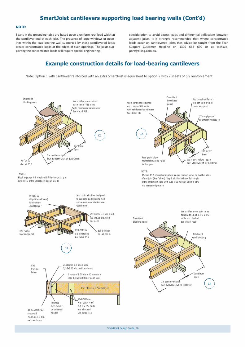
SmartJoist Design Guide 36
Example construction details for load-bearing cantilevers
Note: Option 1 with cantilever reinforced with an extra SmartJoist is equivalent to option 2 with 2 sheets of ply reinforcement.
NOTE: Spans in the preceding table are based upon a uniform roof load width at the cantilever end of each joist. The presence of large windows or open-ings within the load bearing wall supported by these cantilevered joists create concentrated loads at the edges of such openings. The joists sup-porting the concentrated loads will require special engineering
consideration to avoid excess loads and differential deflections between adjacent joists. It is strongly recommended that where concentrated loads occur on cantilevered joists that advice be sought from the Tech Support Customer Helpline on 1300 668 690 or at [email protected].
We b stiffen ers re quiredeac h side o f ALL jo istswith reinfo rced ca ntileve rsSee detail F13
NOT E:
Bloc k together full length with fi ller blo cks as p erdeta il F15 of the SmartJo ist Des ign Gui de
Can tileverSpa n
2 x cantilever spa nbut MINIMUM of 12 00mm
Sma rtJoist bloc king pa nel
NOT E:
Equ al to ca ntileve r spanbut MINIMUM of 60 0mm
Can tileverSpa n
15mm F1 1 stru ctural ply is required on one or both side sof th e joist (See Ta bles). Depth shall m atch th e full h eightof th e Sma rtjoist. Nail wi th 3.15 x 65 n ails at 1 00mm ctrs
in a stagge red pattern.
Face grain of ply rein forcem ent pa rallel to th e span
Sma rtJoistblo cking pan el
17m m plyw ood or SmartRi m closu re
Atta ch web -stiffen ersto e ach sid e of joi stove r sup port
Ref er to
detail F15
Inve rted face -moun t or u niversa lhan ger
25x 10mm G.I.
stra p with7/3 5x3.1 5 dia. nail s each end
LVL trim mer bea m
We b Stiffen erNai l with 4 of 3.1 5 x 65 nails and clinche dSee detail F13
25x 10mm G.I. stra p with7/3 5x3.15 dia. na ils each end
3 ro ws of 3 .75 dia x 40 m m nai lsinto the we b-stiffe ner ea ch side
Soli d timbe ror L VL bea m
Sma rtJoist shall be design edto s upport load-be aring w allabo ve whe n not s tacked overwal l below .
Sma rtJoistbloc king pa nel
INV ERTED(Up side- down )Face -Moun tJois t Hange r
We b-Stiffen er
to b e insta lledSee detail F13
25x 10mm G.I. stra p with
7/3 5x3.15 dia. na ilseac h end
We b stiffen ers re quiredeac h side o f ALL jo istswith reinfo rced ca ntileve rsSee detail F13
Can tileverSpa n
2 x cantilever spa nbut MINIMUM of 60 0mm
Sma rtJoist bloc king pa nel
We b stiffen er on both sid esNai l with 4 of 3 .15 x 65 nail s and c linchedSee detail F12b
Rim board end blockin g
Can tileve red SmartJo ist
C1 C2
C3
C4
SmartJoist cantilevers supporting load bearing walls (Cont’d)

SmartJoist Design Guide 37
SmartJoists supporting parallel load-bearing walls
Fitted floors
Double SmartJoistsrequired for fixing offloor and cei ling, and when required by tablebel ow ANDfor SmartJoists wi th 40 mm wide flanges
Platform floors
Single Smart Joist wit h flange > 50mm may be used,but requ iresalt ernat ive fi xing for ceili ng.NOT sui table forSmartJo ists with40 mm wide flangese.g SJ24 040
span
Joist non-continuously supported by lower wall
Joists continuously supported by lower walls
Fix 90x45 mm F5
compress ion b lockto si ngle rim board whe re load excee ds26.0 kN*
Fix 90x45 mm F5 compress ion b lock to Sm artJoi st wher e load excee ds 6.5 kN*
Con centrated poin t loads (e g, girde r truss es, TG' s all be ams & jamb studs)
Fix 90x45 mm F5compress ion b lockto Sm artJoi st wher eload excee ds 6.5 kN*
Con centrated poin t loads
(e g, girde r truss es, TG' s all be ams & jamb studs)
Con centrated poin t loads (e g, girde r truss es, TG' s all be ams & jamb studs)
Sin gle Smart Joists with flan ge
wid th < plate wid th
Sin gle SmartRim
Sin gle Smart Joists with flan ge
wid th >= plat e wid th
Struts underconcent ratedloads e. t.c.70 x 35 F5squash b lock
Struts underconcent ratedloads e. t.c.70 x 35 F5 squash b lock
Single (and double ) SmartJoists are adequate to transfer uni-formly distributed compression loads up to 29 kN/m per joist from loadbearing walls to a continuous rigid support below. Detail F5 and F8 are used to transfer concentrated loads where walls are perpendicular to the joists. Details F30a, F30b and F30c above must be used to transfer concentrated loads through parallel SmartJoists where the instantaneous reaction exceeds 6.5 kN
and exceeds 26.0 kN for single SmartRim (reaction needs to be factored for load duration) The table below gives allowable spans for single and double joists NOT continuously supported by a parallel wall. Care must always be taken to adequately support the web of the joists from con-centrated point loads from above by adopting details F13.
F30a
F30b
F30c

SmartJoist Design Guide 38
Single SmartJoists supporting parallel load bearing walls
NOTES:
1. Bearing lengths - minimum of 30 mm 2. Wall loads assumed 0.37 kPa 3. Floor load loads 1.5 kPa or 1.8 kN point live load 4. Upper floor dead load 40 kg/m2 . 5. deflection limits: permanent load - span/300 or 12 mm max LL - span/360 or 9 mm max.
Floor load width (mm) 600 600
Roof load width (mm) 1500 3000 5000 1500 3000 5000
SmartJoist code
Roof mass (kg/m2)
Maximum recommended SmartJoist span (mm)
Single Span Continuous Span
SJ20044 40 2450 2250 2050 3450 2900 2400
90 2200 1900 1400 2800 2100 1600
SJ24040 40 2800 2550 2300 3550 3150 2800
90 2500 2150 1750 3100 2550 2000
SJ24051 40 3000 2750 2500 4050 3600 2950
90 2700 2300 1750 3450 2550 2000
SJ24070 40 3300 3000 2700 4300 3600 2950
90 2950 2450 1750 3450 2550 2000
SJ24090 40 3550 3200 2900 4550 4250 3500
90 3150 2700 2150 4100 3050 2300
SJ25570 40 3450 3150 2850 4450 4200 3750
90 3100 2650 2300 4100 3250 2450
SJ30040 40 3350 3100 2800 4050 3600 3150
90 3000 2600 2250 3500 2900 2450
SJ30051 40 3600 3300 3000 4600 4100 3600
90 3250 2800 2250 4000 3300 2550
SJ30070 40 3850 3600 3250 4900 4600 3800
90 3550 3050 2250 4450 3300 2550
SJ30090 40 4050 3800 3500 5200 4850 4450
90 3750 3250 2750 4800 3850 2950
SP30095 40 4150 3900 3600 5300 5000 4400
90 3850 3400 2750 4900 3850 2950
SJ36058 40 4150 3900 3650 5300 5000 4400
90 3850 3400 2800 4850 4000 3100
SJ36090 40 4500 4200 3900 5750 5400 5000
90 4150 3700 3250 5300 4650 3550
SJ40090 40 4750 4450 4150 6100 5700 5350
90 4400 3950 3550 5650 5100 4000
Floor load width (mm) 600 600
Roof load width (mm) 1500 3000 5000 1500 3000 5000
SmartJoist code
Roof mass (kg/m2)
Maximum recommended SmartJoist span (mm)
Single Span Continuous Span
2/SJ20044 40 3200 2950 2700 4200 3950 3700
90 2900 2500 2200 3900 3500 2750
2/SJ24040 40 3650 3350 3050 4600 4300 3950
90 3300 2850 2500 4250 3600 3050
2/SJ24051 40 3850 3600 3300 4850 4550 4250
90 3550 3100 2700 4500 4100 3400
2/SJ24070 40 4100 3850 3600 5200 4900 4550
90 3800 3350 2950 4800 4350 3400
2/SJ24090 40 4350 4050 3800 5500 5150 4850
90 4000 3600 3150 5100 4600 4050
2/SJ25570 40 4250 4000 3750 5400 5050 4750
90 3950 3550 3100 5000 4500 4100
2/SJ30040 40 4150 3900 3650 5250 4950 4500
90 3850 3450 3000 4850 4100 3450
2/SJ30051 40 4350 4100 3850 5550 5200 4850
90 4050 3650 3250 5150 4650 3950
2/SJ30070 40 4650 4400 4100 5950 5550 5200
90 4300 3900 3500 5500 4950 4350
2/SJ30090 40 4950 4650 4350 6250 5900 5500
90 4550 4100 3750 5800 5250 4750
2/SP30095 40 5050 4750 4450 6450 6050 5650
90 4700 4250 3850 5950 5400 4900
2/SJ36058 40 5050 4750 4450 6400 6050 5650
90 4700 4250 3850 5950 5400 4800
2/SJ36090 40 5450 5150 4800 6950 6550 6100
90 5050 4550 4150 6450 5800 5300
2/SJ40090 40 5800 5450 5100 7400 6950 6500
90 5350 4850 4400 6850 6200 5600
Double SmartJoists supporting paral-lel load bearing walls
SmartJoist as rafters
About roofs Roof members are subject to dead and live loads as well as wind loads. These wind loads can act either down onto the roof, or can create an uplift effect. For roofs of light construction, the uplift loads generally control the maximum span, whereas it is usual for dead and live loads to be the controlling factors for heavier roofs (e.g. tiles). SmartJoists, by their large depth to width ratio, perform well in roof situations providing that their
upper and lower flanges have adequate lateral support provided by battens and/or ceiling materials . Due to this fact, the spans in the table below only apply for roofs which meet the following criteria: 1. - Enclosed building
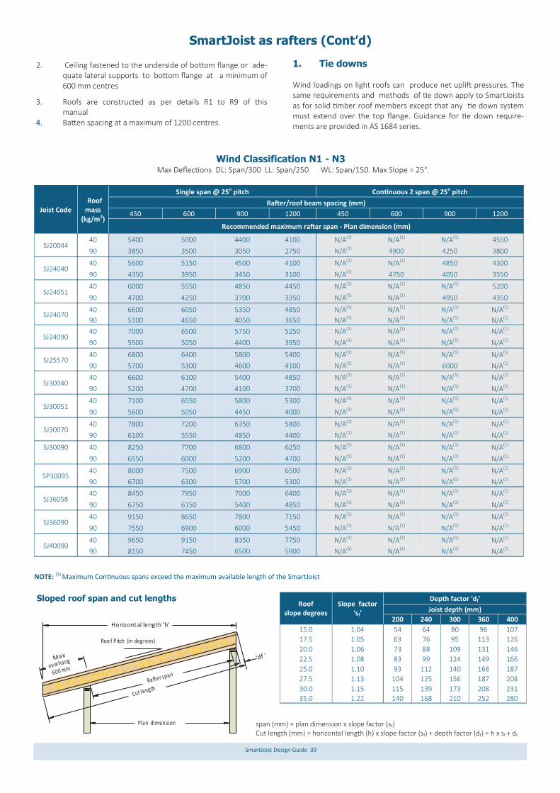
SmartJoist Design Guide 39
2. Ceiling fastened to the underside of bottom flange or ade-quate lateral supports to bottom flange at a minimum of 600 mm centres
3. Roofs are constructed as per details R1 to R9 of this manual
4. Batten spacing at a maximum of 1200 centres.
1. Tie downs Wind loadings on light roofs can produce net uplift pressures. The same requirements and methods of tie down apply to SmartJoists as for solid timber roof members except that any tie down system must extend over the top flange. Guidance for tie down require-ments are provided in AS 1684 series.
Roof slope degrees
Depth factor 'df' Slope factor
‘sf' Joist depth (mm)
200 240 300 360 400
15.0 1.04 54 64 80 96 107
17.5 1.05 63 76 95 113 126
20.0 1.06 73 88 109 131 146
22.5 1.08 83 99 124 149 166
25.0 1.10 93 112 140 168 187
27.5 1.13 104 125 156 187 208
30.0 1.15 115 139 173 208 231
35.0 1.22 140 168 210 252 280
Sloped roof span and cut lengths
Ho rizontal length 'h'
Roo f Pitch (in degrees)
Max
overhang
600 mm
Rafter span
'df '
Plan dimen sion
Cut length
span (mm) = plan dimension x slope factor (sf) Cut length (mm) = horizontal length (h) x slope factor (sf) + depth factor (df) = h x sf + df
Joist Code Roof mass
(kg/m2)
Single span @ 25o pitch Continuous 2 span @ 25o pitch
Rafter/roof beam spacing (mm)
450 600 900 1200 450 600 900 1200
Recommended maximum rafter span - Plan dimension (mm)
SJ20044 40 5400 5000 4400 4100 N/A(1) N/A(1) N/A(1) 4550
90 3850 3500 3050 2750 N/A(1) 4900 4250 3800
SJ24040 40 5600 5150 4500 4100 N/A(1) N/A(1) 4850 4300
90 4350 3950 3450 3100 N/A(1) 4750 4050 3550
SJ24051 40 6000 5550 4850 4450 N/A(1) N/A(1) N/A(1) 5200
90 4700 4250 3700 3350 N/A(1) N/A(1) 4950 4350
SJ24070 40 6600 6050 5350 4850 N/A(1) N/A(1) N/A(1) N/A(1)
90 5100 4650 4050 3650 N/A(1) N/A(1) N/A(1) N/A(1)
SJ24090 40 7000 6500 5750 5250 N/A(1) N/A(1) N/A(1) N/A(1)
90 5500 5050 4400 3950 N/A(1) N/A(1) N/A(1) N/A(1)
SJ25570 40 6800 6400 5800 5400 N/A(1) N/A(1) N/A(1) N/A(1)
90 5700 5300 4600 4100 N/A(1) N/A(1) 6000 N/A(1)
SJ30040 40 6600 6100 5400 4850 N/A(1) N/A(1) N/A(1) N/A(1)
90 5200 4700 4100 3700 N/A(1) N/A(1) N/A(1) N/A(1)
SJ30051 40 7100 6550 5800 5300 N/A(1) N/A(1) N/A(1) N/A(1)
90 5600 5050 4450 4000 N/A(1) N/A(1) N/A(1) N/A(1)
SJ30070 40 7800 7200 6350 5800 N/A(1) N/A(1) N/A(1) N/A(1)
90 6100 5550 4850 4400 N/A(1) N/A(1) N/A(1) N/A(1)
SJ30090 40 8250 7700 6800 6250 N/A(1) N/A(1) N/A(1) N/A(1)
90 6550 6000 5200 4700 N/A(1) N/A(1) N/A(1) N/A(1)
SP30095 40 8000 7500 6900 6500 N/A(1) N/A(1) N/A(1) N/A(1)
90 6700 6300 5700 5300 N/A(1) N/A(1) N/A(1) N/A(1)
40 8450 7950 7000 6400 N/A(1) N/A(1) N/A(1) N/A(1)
SJ36058 90 6750 6150 5400 4850 N/A(1) N/A(1) N/A(1) N/A(1)
SJ36090 40 9150 8650 7800 7150 N/A(1) N/A(1) N/A(1) N/A(1)
90 7550 6900 6000 5450 N/A(1) N/A(1) N/A(1) N/A(1)
SJ40090 40 9650 9150 8350 7750 N/A(1) N/A(1) N/A(1) N/A(1)
90 8150 7450 6500 5900 N/A(1) N/A(1) N/A(1) N/A(1)
NOTE: (1) Maximum Continuous spans exceed the maximum available length of the SmartJoist
Wind Classification N1 - N3 Max Deflections DL: Span/300 LL: Span/250 WL: Span/150. Max Slope = 25°.
SmartJoist as rafters (Cont’d)
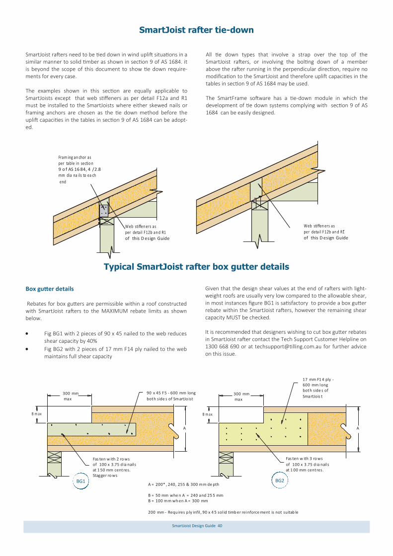
SmartJoist Design Guide 40
Typical SmartJoist rafter box gutter details
A = 200* , 240, 255 & 300 mm de pth
B = 50 mm whe n A = 240 and 25 5 mmB = 100 mm wh en A = 300 mm
200 mm - Requ ires p ly infil , 90 x 4 5 sol id timb er reinforce ment is not suitab le
90 x 45 F5 - 600 mm long
both side s of SmartJo ist300 mm max
B m ax
Fas ten w ith 2 ro wsof 100 x 3.75 d ia nail sat 1 50 mm centres.Stagger ro ws
A
B m ax
A
300 mm max
Fas ten w ith 3 ro ws
of 100 x 3.75 d ia nail sat 1 00 mm centres.
17 mm F1 4 ply - 600 mm longboth side s of
SmartJois t
Box gutter details Rebates for box gutters are permissible within a roof constructed with SmartJoist rafters to the MAXIMUM rebate limits as shown below.
Fig BG1 with 2 pieces of 90 x 45 nailed to the web reduces shear capacity by 40%
Fig BG2 with 2 pieces of 17 mm F14 ply nailed to the web maintains full shear capacity
Given that the design shear values at the end of rafters with light-weight roofs are usually very low compared to the allowable shear, in most instances figure BG1 is satisfactory to provide a box gutter rebate within the SmartJoist rafters, however the remaining shear capacity MUST be checked. It is recommended that designers wishing to cut box gutter rebates in SmartJoist rafter contact the Tech Support Customer Helpline on 1300 668 690 or at [email protected] for further advice on this issue.
SmartJoist rafter tie-down
SmartJoist rafters need to be tied down in wind uplift situations in a similar manner to solid timber as shown in section 9 of AS 1684. it is beyond the scope of this document to show tie down require-ments for every case. The examples shown in this section are equally applicable to SmartJoists except that web stiffeners as per detail F12a and R1 must be installed to the SmartJoists where either skewed nails or framing anchors are chosen as the tie down method before the uplift capacities in the tables in section 9 of AS 1684 can be adopt-ed.
All tie down types that involve a strap over the top of the SmartJoist rafters, or involving the bolting down of a member above the rafter running in the perpendicular direction, require no modification to the SmartJoist and therefore uplift capacities in the tables in section 9 of AS 1684 may be used. The SmartFrame software has a tie-down module in which the development of tie down systems complying with section 9 of AS 1684 can be easily designed.
Fram ing an chor asper table in sectio n 9 o f AS 16 84, 4 /2.8mm dia na ils to ea ch
end
Web stiffen ers asper detail F12b an d R1of this D esign Guide
Web stiffen ers asper detail F12b an d R1of this D esign Guide
BG1 BG2

SmartJoist Design Guide 41
DB902033
SB902045
90
4520
3320
90
42
9780
WPB42080097
Double bevelled bearing plateDB903045
Waling plate bevelbearing plateWPB42080097
Single bevel bearing plateSB900035
Single bevel bearing plateSB900035
SmartFrame bevelled bearing plates
The use of beveled bearing plates makes the use of lightweight SmartJoists as rafters even more attractive, removing the need for most, if not all joist hangers. From its sophisticated wood working equipment such as CNC cutting and machining tools, Tilling Timber can supply ancillary components to further revolu-tionise the rapid and cost effective installation of SmartJoist roof systems
Single and double bevel plates for rafter angles from 6⁰ to 24⁰ slope from 90 mm wide seasoned softwood can be supplied as an integral part of a long span light-weight SmartJoist roof layout
SmartJoist rafters can on request, be supplied plumb cut on either one or both ends
Waler bevel plate for rafter angles 6⁰ to 45⁰ slope from either SmartLVL or seasoned softwood can be supplied as an integral part of a SmartJoist roof layout.
Example SmartFrame bevel plate sizes for 90 mm wide plate, nil front upstand
Roof slope⁰
Height (mm)
Roof slope⁰
Height (mm)
6 9 16 26
8 13 18 29
10 16 20 33
12 19 22 36
14 22 24 40
90
36
Notes:
SmartFrame bevelled bearing plates, where requested, are designed by the Design Centre into a SmartJoist roof system layout. They are not sold individually as they are custom made only for the associated SmartFrame roof system and are not a stocked item
SmartFrame bevelled bearing plates can be supplied in seasoned softwood or Smart LVL, depending upon the application
Allow five (5) working days from placement of order for non-retreated members, allow 10 working days for bevelled bearing plates requiring H2f treatment of cut face
Bevelled bearing plates with a nil front upstand (triangular shape) for roof slopes less that 6⁰ are not available because of the difficulty of cutting and small wood volume likely to split when nailed. It is recommended for low slope rafters that a 20 mm front upstand be used
Example single bevel bearing plate
12 mm max.
°30
°01 °0
Optimal 22.5 degrees
A clean, neat screw system that connects both the SmartJoist rafter and Smart-Frame bevelled bearing plate to the wall top plate.
The SDWC Truss screw is tested for uplift and lateral loads between wall plates and vertical wall framing and between the top plate and the roof rafters or trusses. The SDWC screw is recognised for use in chemically treated timber.
Installation Guides and Capacity tables for the SDWC system are available from www.strongtie.com.au.
Strong-Drive® SDWC Truss screw

SmartJoist Design Guide 42
Typical SmartJoist Roof details
Do not b evel c utjois ts beyond insidefac e of w all.
Sma rtJoist blockin g or sim ilar
is re quired at bea ring to provid e late ral sup port.
Bird smou th cu t shallbea r fully a nd not ove rhang the insid e face of the plate.
2/6 5 x 3.15 mmnail s (one eachside )
We b stiff eners requ ired e achsid e of SmartJo ist.Bevel cut stiffe ners to matchroo f slop e. See Detail F12b .
2/6 5 x 3.15mm nails(on e eac h side )
We b stiff eners requ ired e achsid e of SmartJo ist.Bevel cut stiffe ners to match
roo f slop e. See Detail F13.
Fixing plate to b e bol ted to s teel. Bolt si ze as per En g
spe cification
Bird smouth cut sh all bea r fully and n ot over hang th e
insi de face of the plate.
PFC , UC o r UB
Ste el Beam
50mm w idth ove rhang rafte rs. No tch aro und
SmartJois t top flange .
L
L
Jois t shall b e desi gnedusin g design prop erties whe n "L" e xceeds joist spa cing.
Note: Tiedown details to be designed to AS 1684.2 for the respective wind loads with the SmartFrame software
Blo ckingbetw een outr iggersFac e-Mo unt Hanger
(Fo r roof pitch equal/less than 3 de g ONL Y)
Var iable sl ope & skew jois t han ger
25x 1.0mm G.I. strap with 7/3 5 x 3.1 5mmnai ls each end
25x 1.0mm G.I. strap with 7/3 5 x 3.1 5mmnai ls each end
Bevelled webstif fener on
both side s as p er de tail F1 3
Bevelled web stif fener on both side s asper detai l F13
600 mm overhang & bac kspan - 9 0 x 42 LVL1 5 or similar at 60 0 mm centres900 mm overhang & bac kspan- 13 0 x 4 2 LVL1 5 or s imilar at
60 0 mm centres
Warning: Do not allow workers or loads on roof until ALL blocking, hanger, bracing and fastening is completed. See Safety warning
R4
R13
R7a
R3a R3b
R7b
R8
R9c
R9b R6b
R6a R5c
R9a
R5b R5a
R7c
R10b
R10a
R11
R1 R1a
R2
R3a R3b R4
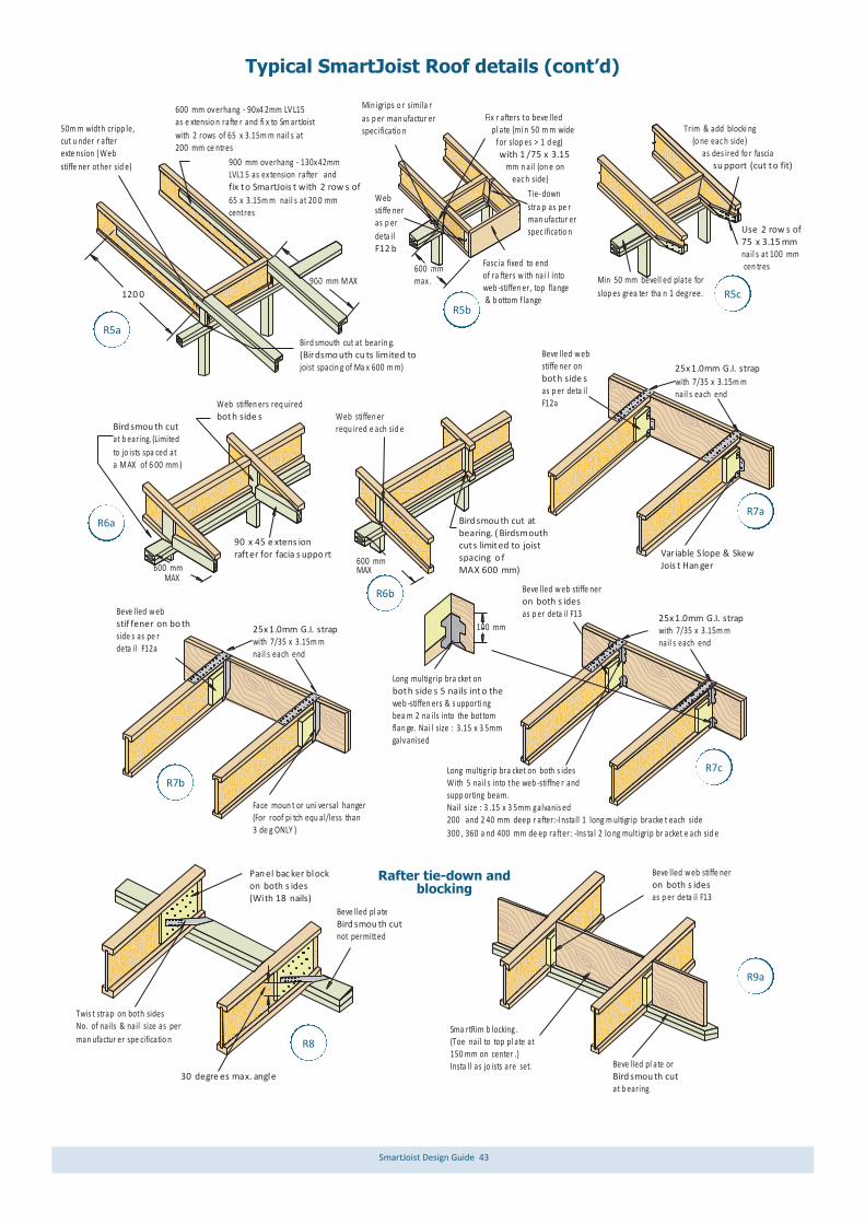
SmartJoist Design Guide 43
Typical SmartJoist Roof details (cont’d)
Web stiffen ers req uiredboth side s
Bird smou th cut at b earing. (Limited
to jo ists spa ced ata M AX of 6 00 mm )
MAX600 mm
90 x 45 e xtens ion rafter for facia s uppo rt
Bird smou th cut at bearing. ( Birdsmouthcuts limited to joistspacing o f MAX 600 mm)MAX
600 mm
Web stiffen er requ ired e ach sid e
Min 50 mm bevell ed plate for
slop es grea ter tha n 1 degree.
Trim & add blocki ng (o ne eac h side) as des ired fo r fascia su pport (cut to fit)
Use 2 row s of 75 x 3.15 mmnail s at 100 mm cen tres
Fix r afters to beve lled pl ate (mi n 50 m m wide for slop es > 1 d eg) with 1 /75 x 3.15 mm n ail (on e on eac h side)
Min igrips o r simila r
as p er man ufactur er spec ificatio n
Tie-down
stra p as pe r man ufactur er spec ificatio n
600 mmmax .
Fasc ia fixed to end of ra fters w ith nai l into web -stiffen er, top flange & b ottom f lange
Web stiffe ner as p er
deta il F12 b
Bird smouth cut at bearin g.(Birdsmo uth cu ts limited tojoist spacin g of Ma x 600 m m)
120 0
50m m width cripp le, cut u nder r after exte nsion (Web
stiffe ner other sid e)
900 mm M AX
Twis t strap on both sidesNo. of nails & nail size as per
man ufactur er spe cificatio n
Pan el bac ker block on both s ides(With 18 nails)
30 degre es max. angle
Beve lled pl ateBird smou th cut not permitted
25x 1.0mm G.I. strap
with 7/35 x 3.15m mnail s each end
Face moun t or uni versal hanger(For roof pi tch equ al/less than 3 de g ONLY )
25x 1.0mm G.I. strap with 7/35 x 3.15m mnail s each end
Variable S lope & SkewJois t Han ger
Beve lled w eb stiffe ner on both side s as p er deta il F12a
Beve lled w eb stif fener on bo thside s as pe rdeta il F12a
25x 1.0mm G.I. strap with 7/35 x 3.15m mnail s each end
Long multigrip bra cket on both s idesWith 5 nail s into the web -stiffne r andsupp orting beam.Nail size : 3 .15 x 3 5mm galvanis ed200 and 2 40 mm deep r after:-I nstall 1 long m ultigrip bracke t each side
300 , 360 a nd 400 mm de ep rafter: -Ins tal 2 lo ng multigrip br acket e ach sid e
Beve lled w eb stiffe neron both s ides as p er deta il F13
100 mm
Long multigrip bra cket on both side s 5 nails into the web -stiffen ers & s upporti ng bea m 2 na ils into the bottomflan ge. Nai l size : 3.15 x 3 5mm galvanised
Sma rtRim b locking.(Toe nail to top pl ate at 150 mm on center .)Insta ll as jo ists are set. Beve lled pl ate or
Bird smou th cut at b earing
Beve lled w eb stiffe neron both s ides as p er deta il F13
600 mm overhang - 90x4 2mm LV L15as e xtensio n rafte r and fi x to Sm artJoist
with 2 rows of 65 x 3.15m m nail s at200 mm ce ntres
900 mm overhang - 130x 42mmLVL1 5 as ex tension rafter andfix to SmartJois t with 2 row s of
65 x 3.15m m nail s at 20 0 mmcentres
R5a
R5b
R5c
R6a
R6b
R7a
R7b
R7c
R8
R9a
Rafter tie-down and blocking

SmartJoist Design Guide 44
Typical SmartJoist Roof details (cont’d)
SmartJois t blo cking
4/3 5 x 3.15 mm na ilsper each b locking
Roo f purlin4/7 5 x 3.15 mm na ilsper each b locking
1/3 5 x 3.15 mm na ilper rafter
2/7 5 x 3.15 mm na ilsper rafter
Batten
Roo f she eting
Dou ble-be velled
plate on be am or wall
RimBoard or filler blo ck on both s ides. (With 12 nails o n eac h side of rid ge)
Dou ble-be velledplate on be am or wall
Nai l backe r blocki ngwith 75 x 3 .15mm nails.Refe r to ta ble belo w for no. of nails required
Bac ker blo ckon both s ides
Fille r bloc kingAs p er deta il F15 or F1 5A
Stra p
Fix rafters to su pportwith 1/75 x 3.15m m nail(one on ea ch side )
Tie-down a s perman ufactu rer spe cificatio n
Bloc king pa nel
Bloc king pa nel
Ceil ing battens fixe d to u ndersid e
(Ma x. batte n spaci ng of 6 00mm)
Ceil ing fixe d to the top of the bo ttom fla nge
Ceil ing fixe d to un derside
Roo f batten
Roo f batten
Roo f batten
Rafter
Rafter
Rafter
Ceil ing
Ceil ing
Ceil ing
Ceil ingbatten
Bevelled plate or Bird smou th cut at be aring
Nai l metal strap to rafter s
and supp orts w ith 3/3 5 x 3.15 mm na ils
Metal strap ove r rafter
Roo f batten
Bevelled plate or Bird smou th cut at be aring
Fix roof b atten torafter with 2/3 5 x 3.1 5mm nails
Fix cut-to -lengthblo cking to sup portwith 4/65 x 3.15m m nailper each b locking
25x 1.0 mm G.I. str ap with 7/3 5 x 3.15 mm na ils eac h end
Fix rafters to su pportwith 1/75 x 3.15m m nail
(one on ea ch side )
Fix roof b atten to
blo cking with 2 /35 x 3 .15mm nails
Ou triggers to LVL Raf ter De tail
Rafters
Trim mers/ Outriggers
Sma rtJOIST Rafters
SmartLVL Rafte rs
R9b
R9c
R10a
R10b R11
R12
R12a
R13
Lateral restraint - SmartJoist blocking fixing
Lateral restraint at supports
Trimming of roof openings
Lateral restraint for rafters - Use of ceiling options to provide lateral support
Outrigger rafters - LVL

SmartJoist Design Guide 45
SmartJoist roof cassettes
The lightweight long spanning SmartJoists are ideal roof compo-nents for mono-slope and pitched roof applications, both parallel and perpendicular to the roof slope. Sophisticated CAD design systems and CNC manufacturing pro-cesses adopted by Tilling Timber nationally has meant that the benefits of offsite manufacture of SmartJoist roof cassettes using SmartJoists and other products from the SmartFrame family of EWP where necessary, had rapidly become mainstream in the Australian market.
Since designing and building the approx. 3600 m2 floor cassettes for the inaugural five (5) storey lightweight framed class 2 building in Australia in 2014, the SmartFrame Design Centre has continued to expand a well experienced dedicated cassette team that spe-cialises in the design and production of shop drawing for sophisti-cated cassettes. For further information about the application of offsite manufac-tured SmartFrame cassettes in your project pleased contact Tech support Helpline on 1300 668 690 or at [email protected].

SmartJoist Design Guide 46
Building envelope watertightness - decks
Deck ledger attachments Many houses have decks attached to them. They are usually attached by first installing a deck ledger to the side of a house. The ledger carries the load for one end of the floor joists of the deck. The ledger and its attachment points penetrate the exterior cladding and must be flashed to protect the wall from rain water running down the cladding. This area of the wall experiences more rain exposure than most others because rain hitting the deck next to the wall splashes against the wall. "Free-standing" decks avoid this problem be-cause they do not penetrate the cladding envelope. As with window and door installations in walls, paying careful attention to flashing details is critical to avoid potential rot and mould of inner non treated wall frames and floor systems. Water from direct rainfall, splash from decks and runoff from incorrectly sloped deck surfaces can leak into the exterior wall where the deck attaches to the house.
Several conditions contribute to the water problem:
The ledger board is simply attached to the house with numerous lag screws or other hardware that penetrate the wall’s cladding and drainage plane, but no flashing has been installed to protect these areas
Water is often trapped behind the ledger board
Upward splashing of rain from the deck adds significant wetting to the cladding, and inadequate flashing results in wetting and rot in the wall’s framing and other internal elements.
Integrating the attachment of the ledger board with the drainage plane behind the wall’s cladding and adding proper flashing will maintain the integrity of the drainage plane and channel water away from the wall’s surface.
Untreated (optional H3) member Min 35 mm thick to support bolting of deck ledger
Protectadeck or similar
Exterior cladding
Exterior cladding
Durability Class 1 or H3 treated timber deck ledger, depth at least 20 mm less than deck joists to prevent water entrapment
Flashing drip edge
Durability Class 1 or H3 treated
Z-flashing
Non treated SmartJoist
Breathable building wrap
Particleboard flooring
Bocoseal 16 or similar peel-and-stickwaterproof membrane
Min 10 mm gapto allow free
draining of deck
Breathable building wrap
316 Grade stainless steelor 300+ gsm hot dippedgalvanised joist hanger*
Stainless steel or hotdipped galvanised bolt*
* Bolt and joist hanger material based upon1. Timber treatment type2. Proximity to the sea3. Proximity to Industrial zones4. Proximity to chemicals/animals/swimming pools
Nail from bottom plate of upper wall frame at regular intervals to allow memberto provide lateral bracingto deck
Example flashing of deck ledger connection to un-treated house frame

SmartJoist Design Guide 47
SmartJoist floor set-downs
Floor set-downs In recent years accessibility considerations are mandated for house construction. This has resulted in the growing use of set-downs to create a “wet room” or “open bathroom” where the edge of shower base is at the same level as the floor, with a small fall to the shower outlet. Typically the entire floor including the shower base is seamlessly tiled.
The different depths and flange width of joists within the SmartJoist range make the creation of set-down areas a simple exercise by adding shallower joists in the set down area, these
shallower joists either being supported on internal/external walls or off trimmers between the deeper joist.
SmartFrame innovation has further simplified the set-down of areas within the most common floor depth 300 mm floor depth by introducing a 255 mm deep set-down joist, the SJ25570. The SJ25570 joist offers a 45 mm set-down from the 300 mm deep joists, BUT, may also be packed up to 300 mm with stock stand-ard 45 mm framing timber.
SJ25570 setdownjoists
70 x 26 packer(Available fromSmartFrame)
6 mm tile underlay 6g screws at
150 mm centres
SJ300 series joistor SJ25570 with45 mm packer
Bead of constructionadhesive
Waterproof showerbase kit
255
+45
= 300
Easy creation of set-down area
SJ25570 + 70 x 45total depth 300 mm
SJ30070 total depth 300 mm
Example “wet room” shower detail
Notes: 1. In the above detail, wet are waterproofing in accordance with NCC volume 2 Part 3.8.1 has been omitted for clarity. It is the users
responsibility to ensure that any areas subject to moisture are correctly detailed as per NCC and /or local authority requirements
2. This is an example using a proprietary waterproof shower base kit with an exterior rim height of 25 mm. Given the prevalence of this size, lengths of 70 x 26 mm packers are available in conjunction with SJ25570 joist orders. These packers are available only with SJ25570 order, and are not a separate stock item
SmartJoist
SJ25570

SmartJoist Design Guide 48
100 0 max
Max
200/250* kg per joist
Max 200/250* kg
per joist100 0 min
100 0 max
160 0 max
160 0 max
100 0 max 120 0
Joist direction
120 0 100 0 max
160 0 max
160 0 max
100 0 min
No materials stacked
in this area !Stair
opening
600
600
600
600
600
600
600
600
600
600
Safe loading of materials on a SmartJoist working platform
IMPORTANT!! Joists must be fully braced of have floor sheeting installed before applying any of the following loads.
* 200 kg per joist for joists less than 240 mm deep * 250 kg per joist for joists 240 mm and greater
Maximum distance to centre of load from face of support = 1600 mm. Maximum of 2 loads can be applied to 1 joist length, providing they are not more than 1600 mm from the face of the wall and a minimum of 1000 mm
between loads as shown.
Notes: 1. Deflection limit is taken as span/200 2. All timber must be kept dry when applying maximum temporary loading 3. Loads are to be spread equally over a minimum of 2 joists, using timber bearers at a minimum of 1200 mm in length or a standard 1200 x 1200 pallet 4. NO loads are to be stacked over any part of the lengths of the joists fixed to an opening header or trimmer joist such as a stair trimmer 5. If no plasterboard is in place under the joists, the bottom flange requires temporary bracing 6. Joists on hangers may require propping 7. If unsure about stacking concentrated loads on SmartJoist working platforms, please contact the SmartFrame Design Centre on 1300 668 690.

SmartJoist Design Guide 49
Fire safety The Building code of Australia became a performance-based code in 1996 (BCA96). The introduction of the BCA along with the chang-es to AS 1530.4 has seen Australia brought into line with interna-tional standards for fire resistance testing. The principle modifica-tion has been to express the test result in terms of the perfor-mance of the specimen Fire Resistance Level (FRL) rather than to assign a single rating as had been the established practice. The outcome of the test is expressed as the number of minutes for which the specimen fulfils the requirements of each of the three criteria, being: i. Structural adequacy ii. Integrity; and iii. Insulation, and expressed in that order The performance of a specimen is then given as the actual time for which the specimen satisfied these criteria, but rounded down to the nearest regulatory requirements. E.g. 60/60/60. Ceiling systems may also be required to provide “Resistance to the Incipient Spread of fire” for a given period of time. This requires the ceiling system to prevent the spread of fire within a roof/ceiling or floor/ceiling cavity by providing adequate thermal insulation to combustibles in this area, avoiding the danger of them igniting. To coincide with the changes, the FWPA produced a set of Wood Solu-tions manuals “Design and construction guide for BCA compliant fire-rated construction” which outlined the BCA requirements for all classes of buildings, design criteria and construction details which were designed to satisfy the BCA requirements. Fire rated floors/ceilings The best information available at this time concludes that the fire resistance for ceiling and floor/ceilings is achieved by the lining material and that alternative joist sizes and material can be substi-tuted in the various certified systems, providing they are designed to support the full loads. The thickness of the fire grade ceiling lining for the relevant FRL is the same as required in the tested systems using solid timber joists. Additional testing have concluded that the following layers of fire rated plasterboard can achieve the FRL and incipient spread of fire as listed in the following table:
The above ratings can be achieved using standard fire grade plas-terboard from some sheet manufacturers. Other manufacturers may however require the use of special fire rated board or may still require the number of layers outlined in the Wood Solutions Design and construction guide for BCA compliant fire-rated construction.
For further details on the various certified systems, see the Wood Solution website www.woodsolutions.com.au or contact the engi-neers on the Tech Support Customer Helpline on 1300 668 690. Sound transmission The ability of walls and floors to reduce noise is measured over the most important part of the hearing range (from 125 to 4000 cycles per second), and the results reduced to a “weighted sound reduc-tion index” or Rw value. In 2004, the BCA introduced the addition of a Spectrum Adaption factor. This Ctr factor takes into account lower frequency level sounds, and has been chosen in large part, in recognition of the problem of the high bass frequency outputs of modern home theatre systems and amplified music systems. Therefore, both the Ctr and the Rw of the building element will now need to be considered. In addition to being rated for airborne sound transmission, floors are also rated by “Impact sound pressure level” or L’n,w plus the spectrum adaption factor Cl values that rate the capacity of floor assemblies to control impact noise such as footfalls. The lower the L’n,w +Cl of the floor, the better the performance of the floor in terms of impact sound insulation The BCA now requires a Rw+Ctr of 50 in floors between sole occu-pancy units and between dwellings and a plant room, lift shaft, stairway, public corridor, public lobby or similar. In 2004, the BCA introduced Deemed-to-satisfy provisions which require the L’n,w +Cl of a floor to be determined by testing in the laboratory. The impact sound insulation requirements for floors in the BCA is L’n,w +Cl not more than 62 for floor separating dwellings and floor separating dwellings from a plant room, lift shaft, stair-way, public corridor, public lobby or similar. The use of light-frame construction systems challenges designers to insulate against noise rather than simply relying on the massiveness of heavy walls and floors. Excellent levels of noise control can be achieved with good acoustics in wood framed structures surfaced with wood structural panels. Sound control can be achieved by applying floor and wall materials over isolated air spaces that ab-sorb sound. The addition of resilient channels to support the ceiling system independently increases the Rw+Ctr and L’n,w +Cl ratings. The best current understanding indicates that the systems – walls, floors and ceiling” as detailed in the Wood Solutions manuals “Design and construction guide for BCA compliant fire-rated con-struction can be used to closely approximate the Rw+Ctr and L’n,w +Cl rating of floor/ceiling systems with SmartJoist floor joists. Work is under way to further investigate the link between joist types and impact sound insulation. Some example systems are shown on the next page as an indica-tion of Fire and Acoustic rated SmartJoist systems. For further details on the various certified systems see www.woodsolutions.com.au or contact the engineers on the Tech Support Customer Helpline on 1300 668 690 or at [email protected]
Fire grade plasterboard FRL Incipient spread
of fire
1 x 13 mm 30/30/30 0
1 x 16 mm 60/60/60 30
2 x 13 mm 60/60/60 30
2 x 16 mm 90/90/90 60
3 x 16 mm 120/120/120 60
Fire safety and sound transmission

SmartJoist Design Guide 50
2 layers 16 mm plasterboard
Floor deck (singleor double layers)
Resiliant channelat 400 mm centres
Cavity Insulation
SJ24040 or larger SmartJoist, at a maximum of 600mm centres
Floor coverings
1 layers 16 mm plasterboard
40 mm thickconcrete screed
Resiliant channelat 400 mm centres
Cavity Insulation
SJ24040 or larger SmartJoist, at a maximum of 600mm centres
Floor coverings
FRL 60/60/60
12 mm thickPlywood
700
CSR R2.0 SOUNDSCREENbatts
CSR R2.0SOUNDSCREENbatts
13 mm fire resistant plaster
Rondo suspended ceiling system
20 mm PROMATECT 100 or18 mm Promat SYSTEMPANEL
Promat 18 mm thickSYSTEMPANEL
SmartJoist
Examples of fire and/or acoustic rated SmartFrame floor assemblies
Lightweight concrete toppings are frequently installed over engi-neered wood floor systems in multi -residential and commercial construction. Such composite floor systems are typically con-structed as fire-rated assemblies with code-compliant fire and acoustic performance. However, In recent years, the wood structural panel industry has developed all-wood floor systems that use single or double-layer floor sheathing meeting both fire and acoustic performance re-quirements without the use of concrete topping.
The diagrams below detail an All-Wood floor system that has been tested to ASTM International. Standard Test Method for Laboratory Measurement of Airborne Sound Transmission Loss of Building Partitions and Elements. ASTME90 (2016) and ASTM International. Standard Classification for Determination of Impact Insulation Class (IIC). ASTME989-06 (2012). Tests to these stand-ard test methods demonstrate that the two systems shown below give very similar airborne sound resistance (STC*) and Impact resistance (IIC*) values. (similar Acoustic performance)
Note: STC and IIC values are US scales and in this example are used to compare systems only. Approximate conversions to Rw and Ln,w scales are available.
For more information about Acoustic rated All -Wood floor systems, contact SmartFrame Tech Support on 1300 668 690
FRL 60/60/60
NOTE:
The examples above are included to demonstrate that SmartFrame lightweight floor systems can easily be designed to provide both acoustic and fire properties that meet the requirement's of the NCC, however, these examples are not to be specified without further expert advice from acoustic and fire experts and /or the inclusion of SmartFrame product into tested and certified proprietary systems, where applicable.

SmartJoist Design Guide 51
Q. Are the glues used in SmartFrame Engineered Wood Products safe? A. Yes, they are safe, Phenolic resins used in our Engineered Wood
Products are stable, polymerised materials. The polymerisation
reaction is non-reversible (i.e. once the polymer is formed, it
doesn’t break down). A wood dust warning label is provided for all
SmartFrame wood products to alert our customers that wood dust
can be generated by sawing, sanding, or machining wood and
wood products.
Q. What is the level of formaldehyde emission from our phenolic-bonded Engineered Wood Products? A. Independent third party testing has confirmed that formalde-hyde emissions from our phenolic-bonded products (i.e. OSB, LVL, and I-Joists) are below 0.5 mg/L under reasonably foreseeable conditions of use, which meets or exceeds the E0 Formaldehyde Emission Class In short, all available information indicates that formaldehyde
levels associated with phenolic resin-bonded wood products are
similar to those of the dimension lumber veneer or other forms of
wood used to make the products.
Q. How much formaldehyde is in our phenolic-bonded, Engineered Wood Products? A. The amount of formaldehyde in our Engineered Wood Products is less than 0.1 percent of the dry weight.
Q. What is being done to reduce the exposure to formaldehyde? A. Formaldehyde is normally present at low levels, usually lower
than 0.03 ppm, in both outdoor and indoor air. Efforts have been
made by both government and industry to reduce exposure to
formaldehyde. A 1985 regulation by the US Department of
Housing and Urban Development (HUD), covering the use of
manufactured pressed wood products in housing was designed to
ensure that indoor levels were below 0.4 ppm. Product standards
established for plywood and particleboard led to significant
reductions in formaldehyde emissions from those products.
Furthermore, HUD acknowledged that phenolic resin bonded
wood products emitted such small quantities of formaldehyde that
these products were exempted from all the testing and
certification requirements of the standards. In Germany, the
German Hazardous Materials regulation, better known as the “E1”
Standard, sets a limit of 1.0 mg/L for formaldehyde emissions from
some wood-based composite products. All available data
indicates that our phenolic bonded Engineered Wood Products
meet the more stringent E0 level.
Q. What affects formaldehyde levels in a home? A. Formaldehyde levels in the indoor air depend mainly on what is releasing the formaldehyde, the temperature, the humidity, and the air exchange rate (i.e. the amount of outdoor air entering or leaving the indoor area) Levels of formaldehyde decrease with increasing air exchange rate, decreasing temperature, and de-creasing humidity.
Adhesive and formaldehyde emission facts sheet
The treatment of timber to extend its service life is covered by AS/NZS 1604. This code identifies the various biological hazards by a hazard class number, with hazard class numbers from H1 - H6. The higher the hazard class number, the greater the severity of the biological hazard. A complete table listing the 6 hazard classes is contained within AS/NZS 1604.1. All SmartJoists are supplied H2s treated per the table below, or alternatively may be after-market H2 treated by an experienced and approved timber preserver.
Water borne treatments are NOT suitable for SmartJoists. It is also NOT recommended that SmartJoists be specified for use outside above ground, even if H3 treated. This is predominately due to the geometric shape of the I-Joist which will not shed water effectively. Further information on treated I-Joists can be obtained on 1300 668 690 or at [email protected]
Hazard Class Exposure Specific service conditions Biological hazard Typical uses
H1* inside, above
ground Completely protected from the weather and well
ventilated, and protected from termites Lyctid borers
Interior beams, stair cases, string-ers
H2s inside, above
ground South of the Tropic of Capricorn ONLY Protected
from weather, Nil leaching Borers and termites
Interior joists, rafters and roof beams
H2 inside, above
ground Protected from weather, Nil leaching Borers and termites
Interior joists, rafters and roof beams
* All SmartJoists are manufactured from materials not susceptible to Lyctid attack
Preservative treatment

Head Office Victoria New South Wales Queensland Western Australia South Australia
31-45 Orchard Street, Kilsyth Vic 3137
109 Kurrajong Avenue, Mt Druitt, NSW 2770
84 Magnesium Drive, Crestmead QLD 4132
10 Cartwright Drive Forrestdale WA 6112
5-9 Woomera Ave Edinburgh SA 5111
email: [email protected] email: [email protected] email: [email protected] email: [email protected] email: [email protected]
Phone +61 3 9725 0222 Phone +61 2 9677 2600 Phone +61 7 3440 5400 Phone +61 8 9399 1609 Phone +61 8 8345 1966
Fax +61 3 9725 3045 Fax +61 2 9677 2500 Fax +61 7 3440 5444 Fax +61 8 9399 1065 Fax +61 8 8345 1977
Design Compendium Contents Interactive Printable PC
Specifications software
Technical Support
Design Guides (PDF)
Technical Illustrations
Fixing Details
Software Tutorial
Never before has so much user-friendly computer power you been unleashed into the hands of building industry
professionals to allow the design and detailing of engineered timber products. This software, in conjunction with the
SmartFrame Design Centre and SmartFrame Engineered Wood products themselves, combines to form the most
sophisticated structural timber option ever available to the Australian market.
The Smart Frame Engineered Timber Solution represents an entirely new and revolutionary concept in the delivery
of the 21st century technology and service to the building industry.
Available from:
SMARTSMARTSMARTFRAME Design Compendium
Sales 1800 33 77 03 Technical support 1300 668 690
© 2018 Tilling Timber Pty Ltd ABN 92 004 621 121 Date of publication January 2018 SmartFrame is a Registered Trademark of Tilling Timber


